comparison of simulation and measurements - · pdf filecomparison of simulation and measure-...
TRANSCRIPT

22 | SIMPACK News | March 2014
CUSTOMER APPLICATION | Gernoth Götz, Bombardier Transportation GmbH
The rail vehicle approval process today is costly and time-consuming. "Virtual testing" using multi-body simulations is one approach to reduce these costs. During the European research project DynoTRAIN, one of the main activities in work package 5 was the comparison of simulations and measurements from on-track tests to develop the process and criteria for model validation. The on-track measurements were carried out with a measurement train in Germany, France, Switzerland and Italy. This ar-
Fig. 1a: MD36 bogie of a Bim 547.5 coach
ticle describes some selected simula-tions with the Bim 547.5 coach using the simulation tool SIMPACK, which have been carried out by Bombardier Trans-portation.
INTRODUCTIONFor the past two decades, Europe has in-creased its cross-border transport of freight and passengers. The European Union is aware that this makes cross-border rail transport a viable alternative to road trans-port. Historically, every country in Europe de-veloped its own railway system with different national rules for test-ing the acceptability of railway vehicles’ running characteristics. Today, it is necessary for cross-border rail transport to be interoperable with various railway systems. The European approach to interoperability led to two European Commission (EC) Council Directives: 96/48/EC on July 23, 1996 on the interoperability
of trans-European high-speed rail systems and 2001/16/EC on March 19, 2001 on the interoperability of the conventional rail systems. At both of these councils, processes to determine standard rail vehicle approval were established. Today, testing vehicle running characteristics is a costly and time-consuming process since the vehicle certi-fication against European standards (EN), like EN 14363 [1], requires multiple field tests. Unexpected environmental or other
boundary conditions influence the results so that field tests have to be repeated several times in order to cover the possible
range of circumstances, increasing costs and duration of vehicle approval. One approach to reduce this effort could be "virtual test-ing" using numerical multi-body simulations (MBS). For the application of this methodol-ogy, the validation of the simulation model is essential.
“Today, it is necessary for cross-border rail transport to be
interoperable with various railway systems.”
Comparison of Simulation and Measurements
Ready for Print - 08.01.2014
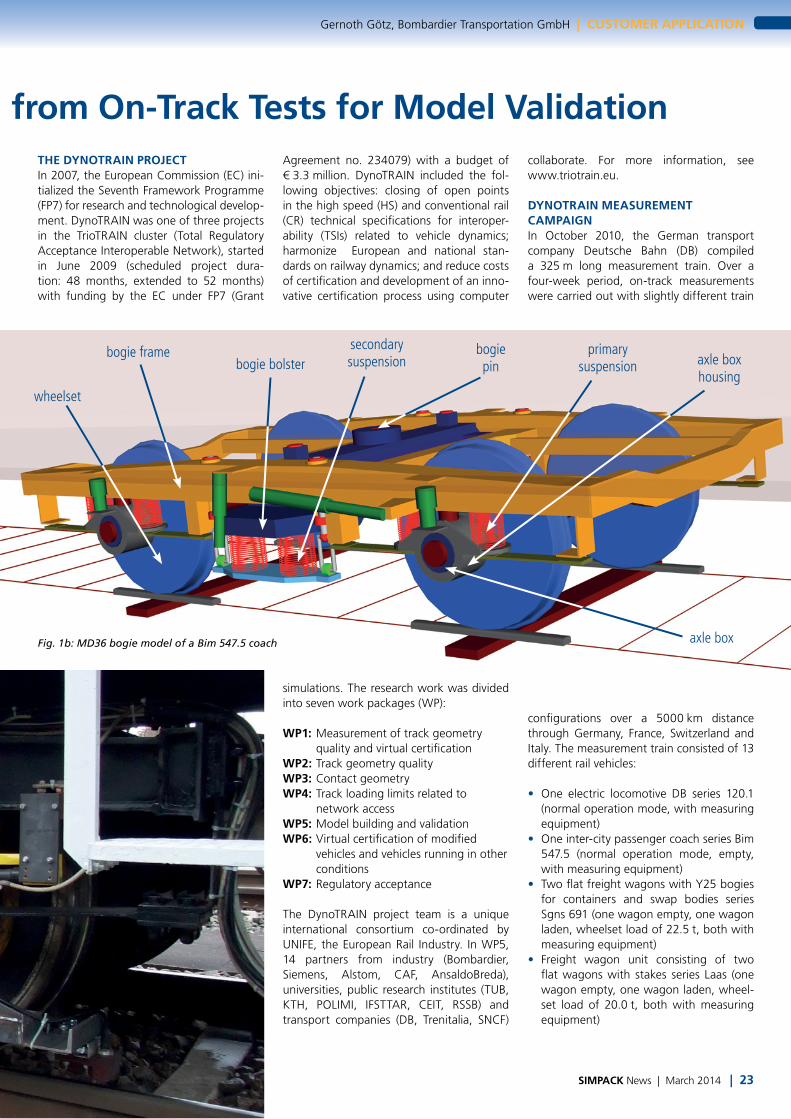
bogie frame secondary suspensionbogie bolster
wheelset
bogie pin
primary suspension axle box
housing
axle box
SIMPACK News | March 2014 | 23
Gernoth Götz, Bombardier Transportation GmbH | CUSTOMER APPLICATION
from On-Track Tests for Model ValidationTHE DYNOTRAIN PROJECTIn 2007, the European Commission (EC) ini- tialized the Seventh Framework Programme (FP7) for research and technological develop-ment. DynoTRAIN was one of three projects in the TrioTRAIN cluster (Total Regulatory Acceptance Interoperable Network), started in June 2009 (scheduled project dura-tion: 48 months, extended to 52 months) with funding by the EC under FP7 (Grant
Agreement no. 234079) with a budget of € 3.3 million. DynoTRAIN included the fol-lowing objectives: closing of open points in the high speed (HS) and conventional rail (CR) technical specifications for interoper-ability (TSIs) related to vehicle dynamics; harmonize European and national stan-dards on railway dynamics; and reduce costs of certification and development of an inno-vative certification process using computer
simulations. The research work was divided into seven work packages (WP):
WP1: Measurement of track geometry quality and virtual certification
WP2: Track geometry qualityWP3: Contact geometryWP4: Track loading limits related to
network accessWP5: Model building and validationWP6: Virtual certification of modified
vehicles and vehicles running in other conditions
WP7: Regulatory acceptance
The DynoTRAIN project team is a unique international consortium co-ordinated by UNIFE, the European Rail Industry. In WP5, 14 partners from industry (Bombardier, Siemens, Alstom, CAF, AnsaldoBreda), universities, public research institutes (TUB, KTH, POLIMI, IFSTTAR, CEIT, RSSB) and transport companies (DB, Trenitalia, SNCF)
collaborate. For more information, see www.triotrain.eu.
DYNOTRAIN MEASUREMENT CAMPAIGNIn October 2010, the German transport company Deutsche Bahn (DB) compiled a 325 m long measurement train. Over a four-week period, on-track measurements were carried out with slightly different train
configurations over a 5000 km distance through Germany, France, Switzerland and Italy. The measurement train consisted of 13 different rail vehicles:
• One electric locomotive DB series 120.1 (normal operation mode, with measuring equipment)
• One inter-city passenger coach series Bim 547.5 (normal operation mode, empty, with measuring equipment)
• Two flat freight wagons with Y25 bogies for containers and swap bodies series Sgns 691 (one wagon empty, one wagon laden, wheelset load of 22.5 t, both with measuring equipment)
• Freight wagon unit consisting of two flat wagons with stakes series Laas (one wagon empty, one wagon laden, wheel-set load of 20.0 t, both with measuring equipment)
Fig. 1b: MD36 bogie model of a Bim 547.5 coach
Ready for Print - 08.01.2014
1.028 1.027 1.026 1.025 1.024
80
70
60
50
40
30
20
Whe
el lo
ad Q
[kN
]
Distance [m] x105
Simulation initial modelSimulation adjusted modelMeasurements
24 | SIMPACK News | March 2014
CUSTOMER APPLICATION | Gernoth Götz, Bombardier Transportation GmbH
• One DB RAILab coach (DB Rolling Analy-sis and Inspection Laboratory for the measurement of track geometry, track irregularities and rail profiles)
• One measuring coach with equipment for data recording of locomotive, pas-senger and freight coaches
• Six brake coaches
During the test campaign, the vehicle dynamics of the locomotive, the pas-senger and the freight coaches were measured using the following mea-surement equipment:
• Instrumented wheelsets to measure the rail-wheel contact forces Y (lateral force), Q (vertical force) and Tx (longitudi-nal force)
• Acceleration sensors to measure the vertical and lateral accelerations of axle boxes, bogie frames and car body
• Displacement sensors to measure the relative displacements in the primary and secondary suspension.
At each vehicle, around 50 measuring channels were recorded with a maximum sampling rate of 1200 Hz depending on the recorded quantity. The
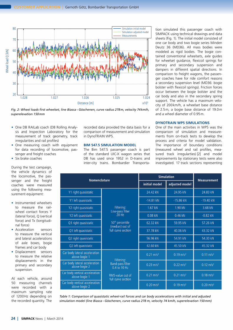
Table 1: Comparison of quasistatic wheel-rail forces and car body accelerations with initial and adjusted simulation model (line Biasca – Göschenen, curve radius 278 m, velocity 74 km/h, superelevation 150 mm)
Fig. 2: Wheel loads first wheelset, line Biasca – Göschenen, curve radius 278 m, velocity 74 km/h, superelevation 150 mm
recorded data provided the data basis for a comparison of measurement and simulation in DynoTRAIN WP5.
BIM 547.5 SIMULATION MODELThe Bim 547.5 passenger coach is part of the standard UIC-X wagon series that DB has used since 1952 in D-trains and inter-city trains. Bombardier Transporta-
tion simulated this passenger coach with SIMPACK using technical drawings and data sheets (Fig. 1). The initial model consisted of one car body and two bogie series Minden Deutz 36 (MD36). All mass bodies were modeled as rigid bodies. The bogie con-tained conventional wheelsets, axle guides for wheelset guidance, flexicoil springs for primary and secondary suspension and dampers in different spatial directions. In comparison to freight wagons, the passen-ger coaches have for ride comfort reasons a secondary suspension level (MD36: bogie bolster with flexicoil springs). Friction forces occur between the bogie bolster and the car body and also in the secondary spring support. The vehicle has a maximum velo-city of 200 km/h, a wheelset base distance of 2.5 m, a bogie base distance of 19.0 m and a wheel diameter of 0.95 m.
DYNOTRAIN WP5 SIMULATIONSOne of the main activities in WP5 was the comparison of simulation and measure-ments from on-track tests to develop the process and criteria for model validation. The importance of boundary conditions (measured wheel and rail profiles, mea-sured track irregularties) [2] and model improvements by stationary tests were also investigated. 17 track sections representing
Ready for Print - 08.01.2014

-6 -5 -4 -3 -2 -1 0 1 2 3 4 5 6
25
20
15
10
5
0
-5
-10
-15
-20
-25
Torq
ue [k
Nm
]
Angle [º]
Measurement 1Measurement 2Simulation (initial model)Simulation (adjusted model)
SIMPACK News | March 2014 | 25
Gernoth Götz, Bombardier Transportation GmbH | CUSTOMER APPLICATION
Fig. 3: Bogie rotation test results in comparison with simulation using initial vehicle model and model after adjustment
all four test zones according to EN 14363 [1] were defined to carry out the comparisons with the on-track tests. Furthermore, differ-ent groups of stationary tests were defined to compare their results with simulations. The sequence of the simulation activity was as follows: initially, the simulation model based on technical drawings and data sheets was only compared with on-track tests in straight sections with a check on the wheel loads (to adjust the car body mass properties), but without comparison to stationary tests. To analyze the effect of measured boundary conditions, the simu-lation results, based on different com-binations of measured and standard boundary conditions, were compared to the on-track measurements. In the next step, the simulation model was compared to defined stationary test groups. If pos-sible, the simulation model was improved to reduce the difference between simulation and measurement of stationary tests. Sub-sequently the same on-track comparisons had been carried out again. The purpose of the simulation activity was to highlight the information about the need for sta-tionary tests and track parameters (wheel profile, rail profile and track irregularity). Fig. 2 shows the comparison of the simulat-ed and measured Q forces at the first wheel-
set based on one exemplary track part from the Swiss line Biasca – Göschenen (curve radius R = 295 m, velocity v = 74 km/h, superelevation u = 150 mm). To make the calculation as realistic as possible, bound-ary conditions (measured wheel and rail profiles, measured track geometry and track irregularity data) were used. Additionally, in Table 1 some selected calculated wheel-rail forces and some selected acceleration RMS values are shown. The comparisons with stationary tests and other adjustments led
to a final model. The selected results under the same boundary conditions were also included in Fig. 2 and Table 1.
By using the final adjusted model, the qua-sistatic differences between simulation and measurements in the Q-forces were slightly reduced. This was mainly dependent on the adjustment of the height of the car body center of gravity. Fig. 3 shows exemplary comparisons with stationary tests on the results of the bogie rotation test. The main difference between the initial simulated and measured torque hysteresis curves can be observed for rota-tion angles between ±4 and ±4.5 degrees. In the initial simulation model, the charac-teristic of the secondary longitudinal bump stop between the bogie frame and bolster includes a free play. This characteristic was
estimated and represented an uncertain model parameter. The approach used to improve the simulation model was a reduc-tion of this free play to zero and a new bump stop characteristic. The comparison of the improved model demonstrates very good agreement between simulation and measurement.
CONCLUSIONThe complete analysis of the simulation results of all vehicles and the proposed process and criteria for model validation has been published in the final WP5 deliverable and at conferences IAVSD 2013 in Qingdao, China [3] and Bogie '13 in Budapest, Hun-gary [4]. Based on the proposed validation methodology in WP5, the Bim 547.5 vehicle model fulfils the validation limits and can therefore be regarded as validated. The ve-hicle model is ready to use for virtual vehicle approval. The following conclusions can be drawn regarding the comparisons between simulation and measurements:
• Measured track irregularities as well as measured rail and wheel profiles improve the accuracy of simulation results com-pared to on-track measurements.
• Stationary tests can be used for model im-provements if there are uncertain vehicle parameters. Due to a good data basis for the Bim 547.5 coach, the vehicle model improvement by comparisons with sta-tionary tests was only marginal; the main improvement was achieved by compari-sons with on-track test measurements.
REFERENCES[1] EN 14363 Railway Applications — Testing for the Acceptance of Running Characteristics of Railway Vehicles — Testing of Running Behaviour and Stationary Tests, CEN, Brussels, 2005.[2] Schelle, H., Hecht, M.: Testing for the Ac-ceptance of Running Characteristics: Influence of Boundary Conditions on the Simulation, ZEV Rail, August 2013[3] Polach, O., Böttcher, A.: A new Approach to Define Criteria for Rail Vehicle Model Validation. 23rd International Symposium on Dynamics of Vehicles on Roads and Tracks, Qingdao, China, August 19–23, 2013[4] Polach, O., Böttcher, A., Vannucci, D., Sima, J., Schelle, H., Chollet, H., Götz, G., Garcia Prada, M., Nicklisch, D., Mazzola, L., Berg, M., Osman, M.: Validation of Multi-body Models for Simulations in Authorisation of Rail Vehicles. 9th International Conference on Railway Bogies and Running Gears, Budapest, Hungary, 9–12 September, 2013
“To analyze the effect of measured boundary conditions,
the simulation results, were compared to the on-track measurements.”
Ready for Print - 08.01.2014