comparison of short-channel effects in monolayer mos2 ... · comparison of short-channel effects in...
TRANSCRIPT
Comparison of short-channel effects in monolayer MoS2 based junctionless andinversion-mode field-effect transistorsTarun Agarwal, Bart Sorée, Iuliana Radu, Praveen Raghavan, Gianluca Fiori, Giuseppe Iannaccone, AaronThean, Marc Heyns, and Wim Dehaene Citation: Applied Physics Letters 108, 023506 (2016); doi: 10.1063/1.4939933 View online: http://dx.doi.org/10.1063/1.4939933 View Table of Contents: http://scitation.aip.org/content/aip/journal/apl/108/2?ver=pdfcov Published by the AIP Publishing Articles you may be interested in Gate controlled electronic transport in monolayer MoS2 field effect transistor J. Appl. Phys. 117, 104307 (2015); 10.1063/1.4914954 Contact-dependent performance variability of monolayer MoS2 field-effect transistors Appl. Phys. Lett. 105, 213508 (2014); 10.1063/1.4902866 Growth-substrate induced performance degradation in chemically synthesized monolayer MoS2 field effecttransistors Appl. Phys. Lett. 104, 203506 (2014); 10.1063/1.4873680 Electrical performance of monolayer MoS2 field-effect transistors prepared by chemical vapor deposition Appl. Phys. Lett. 102, 193107 (2013); 10.1063/1.4804546 A first-principles study on the effect of biaxial strain on the ultimate performance of monolayer MoS2-baseddouble gate field effect transistor J. Appl. Phys. 113, 163708 (2013); 10.1063/1.4803032
Reuse of AIP Publishing content is subject to the terms at: https://publishing.aip.org/authors/rights-and-permissions. Download to IP: 131.114.197.246 On: Mon, 01 Aug
2016 07:37:02

Comparison of short-channel effects in monolayer MoS2 based junctionlessand inversion-mode field-effect transistors
Tarun Agarwal,1,2,a) Bart Sor�ee,1,2,3 Iuliana Radu,2 Praveen Raghavan,2 Gianluca Fiori,4
Giuseppe Iannaccone,4 Aaron Thean,2 Marc Heyns,2 and Wim Dehaene1
1Department of Electrical Engineering, Katholieke Universiteit Leuven, Heverlee 3001, Belgium2Interuniversity Microelectronics Centre (IMEC), Heverlee 3001, Belgium3Department of Physics, Universiteit Antwerpen, 2020 Wilrijk, Belgium4Dipartimento di Ingegneria dell’Informazione, Universita’ di Pisa, Via Caruso 16, 56122 Pisa, Italy
(Received 5 August 2015; accepted 13 December 2015; published online 15 January 2016)
Conventional junctionless (JL) multi-gate (MuG) field-effect transistors (FETs) require
extremely scaled channels to deliver high on-state current with low short-channel effect related
leakage. In this letter, using ultra-thin 2D materials (e.g., monolayer MoS2), we present compari-
son of short-channel effects in JL, and inversion-mode (IM) FETs. We show that JL FETs exhibit
better sub-threshold slope (S.S.) and drain-induced-barrier-lowering (DIBL) in comparison to IM
FETs due to reduced peak electric field at the junctions. But, threshold voltage (VT) roll-off with
channel length downscaling is found to be significantly higher in JL FETs than IM FETs, due to
higher source/drain controlled charges (dE/dx) in the channel. Further, we show that although VT
roll-off in JL FETs improves by increasing the gate control, i.e., by scaling the oxide, or channel
thickness, the sensitivity of threshold voltage on structural parameters is found out to be high.VC 2016 AIP Publishing LLC. [http://dx.doi.org/10.1063/1.4939933]
Novel materials and device structures have been explored
in order to continue scaling of MOSFET devices. Multi-gate
(MuG) field-effect transistors (FETs), due to their excellent
gate control, are being pursued for current, and upcoming
technology nodes. Moreover, junctionless (JL) MuGFET has
been proposed as a potential future device option showing bet-
ter scalability, and fabrication simplicity in comparison to
inversion-mode (IM) FETs. Due to its operation based on
pinch-off of the channel by means of depletion, JL FETs
require extremely scaled channels, or body in order to achieve
better gate control, and low leakage.1,2
Recently, the emergence of a class of 2D semiconduct-
ing materials such as transition metal dichalcogenides
(TMDs) have enabled the possibility of atomic thin channels
in FETs for better gate control. For example, monolayer
MoS2 FET has been shown to have better scalability than an
ultra-thin-body (UTB) Si FET due to monolayer thin body,
and higher effective mass, resulting in reduced direct source-
to-drain tunneling.3 Moreover, a sub-threshold slope (S.S.)
of 60 mV/dec has been demonstrated in monolayer WSe2
FET.4
In this letter, we present a study discussing channel length
scaling of monolayer MoS2 based junctionless and inversion-
mode FETs. Using atomistic two-band ballistic quantum
transport simulations, we show that JL FETs promise better
scalability than IM FETs considering short-channel effects
(SCEs) such as S.S. and drain-induced-barrier-lowering
(DIBL). But, surprisingly JL FETs show worse threshold volt-
age (VT) control with channel length downscaling in compari-
son to IM FETs, resulting in higher VT roll-off. We further
discuss the underlying mechanism for such improvement in
S.S. and DIBL, and reduction of threshold voltage with
channel length downscaling. It is explained that although
JL FETs manifest reduced electric field at the junctions in
comparison to IM FETs, JL FETs also show higher gradient
of lateral electric field in channel, i.e., higher source/drain
controlled charges, and thus lower VT with channel length
downscaling. We further show that we require better gate con-
trol in JL FETs than IM FETs for lower VT roll-off, which can
be achieved by further scaling the oxide thickness or the chan-
nel thickness.
Monolayer MoS2 based IM and JL FETs in double-gate
configuration are schematically shown in Fig. 1. It is important
to note here that we use abrupt source/drain junctions, and no
gate overlap in IM FETs to compare both non-optimized IM
and JL FETs with same structural parameters such as oxide
thickness (tHfO2) and channel length (LCH). Moreover, we use
FIG. 1. Schematic of monolayer MoS2 based (a) inversion-mode FET and
(b) junctionless FET in double-gate configuration with LS¼LD¼ 15 nm,
nþdoping of 1.5 � 1013 cm�2, tHfO2¼ 4:9 nm with �HfO2
¼ 25, tCH¼ 0.7 nm,
and LCH¼ 6–30 nm.a)Electronic mail: [email protected].
0003-6951/2016/108(2)/023506/4/$30.00 VC 2016 AIP Publishing LLC108, 023506-1
APPLIED PHYSICS LETTERS 108, 023506 (2016)
Reuse of AIP Publishing content is subject to the terms at: https://publishing.aip.org/authors/rights-and-permissions. Download to IP: 131.114.197.246 On: Mon, 01 Aug
2016 07:37:02
same doping concentration of 1.5 � 1013 cm�2 for nþ doping
in JL FETs, and source/drain regions for IM FETs using sim-
ilar chemical doping techniques as demonstrated in Ref. 4,
while the MoS2 channel in IM FET is assumed to be intrinsi-
cally n� doped from the environment, as reported in experi-
mental works such as in Ref. 5. The electrical characteristics
of both IM and JL FETs are simulated using two-band tight
binding (TB) Hamiltonian with an open source quantum trans-
port simulation framework based on self-consistent solution of
Poisson and Schr€odinger equation in non-equilibrium Green’s
function framework.6 Further, the two-band Hamiltonian can
be defined as a 2 � 2 Hamiltonian matrix, which is based on a
unit cell of two-dissimilar atoms such M and X in MX2 materi-
als, and can be written as
HCH ¼EC tf ðkÞ
tf �ðkÞ EV
� �; (1)
where EC and EV represent bottom of conduction band and
the top of the valence band, which is related to bandgap (EG)
of the material as: EG¼EC�EV. While t represents in-plane
hopping energy which is fitted for a specific effective mass
(m*), and f(k) function, due to nearest neighbors, can be
written as
f kð Þ ¼ e ikya=ffiffi3pð Þ þ 2e �ikya=2
ffiffi3pð Þ cos
kxa
2
� �: (2)
Here, kx and ky are wave vectors in x and y directions of our
device, while a represents distance between M and X atoms.
Further, using secular equation, we obtain dispersion relation
for two-band model given as
E6 kð Þ ¼EC þ EVð Þ6
ffiffiffiffiffiffiffiffiffiffiffiffiffiffiffiffiffiffiffiffiffiffiffiffiffiffiffiffiffiffiffiffiffiffiffiffiffiffiffiffiffiffiffiffiffiffiffiEC � EVð Þ2 þ 4t2jf kð Þj2
q2
; (3)
which provides a good approximation for lowest conduction
band, and highest valance band of monolayer MX2 materials
for the considered bias ranges. For monolayer MX2 materi-
als, the two-band Hamiltonian parameters are calculated
using the effective mass of conduction (n-FET) or valence
band (p-FET), and bandgap of the material.7 Further, we
extend the model for bilayer MX2 materials using an inter-
layer hopping parameter in the Hamiltonian, accounting for
inter-layer coupling between the two layers.8 Here, mono-
layer MoS2 channel is modeled with an electron effective
mass of 0.45 m0, and bandgap energy of 1.8 eV, while the
bilayer MoS2 channel is modeled with an electron effective
mass of 0.62 m0 and a bandgap of 1.3 eV.
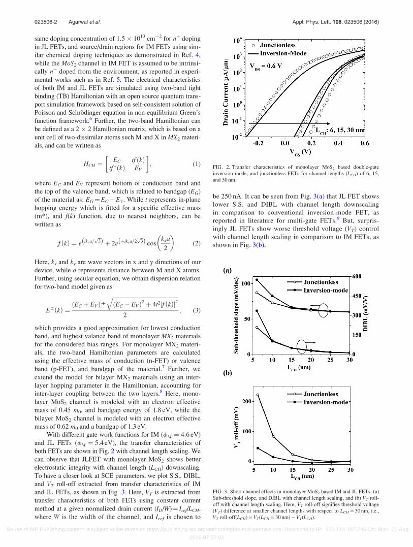
With different gate work functions for IM (/M ¼ 4:6 eV)
and JL FETs (/M ¼ 5:4 eV), the transfer characteristics of
both FETs are shown in Fig. 2 with channel length scaling. We
can observe that JLFET with monolayer MoS2 shows better
electrostatic integrity with channel length (LCH) downscaling.
To have a closer look at SCE parameters, we plot S.S., DIBL,
and VT roll-off extracted from transfer characteristics of IM
and JL FETs, as shown in Fig. 3. Here, VT is extracted from
transfer characteristics of both FETs using constant current
method at a given normalized drain current (ID/W)¼ Iref/LCH,
where W is the width of the channel, and Iref is chosen to
be 250 nA. It can be seen from Fig. 3(a) that JL FET shows
lower S.S. and DIBL with channel length downscaling
in comparison to conventional inversion-mode FET, as
reported in literature for multi-gate FETs.9 But, surpris-
ingly JL FETs show worse threshold voltage (VT) control
with channel length scaling in comparison to IM FETs, as
shown in Fig. 3(b).
FIG. 2. Transfer characteristics of monolayer MoS2 based double-gate
inversion-mode, and junctionless FETs for channel lengths (LCH) of 6, 15,
and 30 nm.
FIG. 3. Short channel effects in monolayer MoS2 based IM and JL FETs. (a)
Sub-threshold slope, and DIBL with channel length scaling, and (b) VT roll-
off with channel length scaling. Here, VT roll-off signifies threshold voltage
(VT) difference at smaller channel lengths with respect to LCH¼ 30 nm, i.e.,
VT roll-off(LCH)¼VT(LCH¼ 30 nm)�VT(LCH).
023506-2 Agarwal et al. Appl. Phys. Lett. 108, 023506 (2016)
Reuse of AIP Publishing content is subject to the terms at: https://publishing.aip.org/authors/rights-and-permissions. Download to IP: 131.114.197.246 On: Mon, 01 Aug
2016 07:37:02

To understand the underlying mechanism for such
improvement in S.S. and DIBL, we plot the off-state conduc-
tion band energy minima (EC) along the channel, showing
the source-to-channel barrier in off-state (VT� 1/3*VDD)
which effectively determines the off-state current. Fig. 4(a)
shows the off-state EC(x) along the channel at the middle of
the width of monolayer MoS2 channel. It can be observed
from Fig. 4(a) that both height and width of source/channel
barrier are larger for JL FETs in comparison to IM FETs. The
larger width of the barrier prevents source-to-drain direct tun-
neling components, resulting in overall lesser leakage current.
Further, as shown in Fig. 4(b), the absolute value of lateral
electric field at source/channel, and channel/drain junctions
are significantly lower in JL FETs in comparison to IM FETs,
resulting in larger depletion lengths inside the drain extension,
and thus lowering the effect of drain bias on source/channel
barrier in JL FETs. Deep depletion inside source/drain exten-
sions has been reported to result in improvement in S.S. and
DIBL in JL FETs in comparison to IM FETs, which effec-
tively results in larger width of the barrier and lower lateral
electric fields at the junctions in JL FETs.10,11
But, surprisingly JL FET exhibits larger VT roll-off in
comparison to IM FET due to higher source/drain controlled
charges inside channel at downscaled channel lengths. To
understand it quantitatively, we can write charge density
inside monolayer MoS2 channel (n2D) as
n2D ¼ nG þ nSD: (4)
Here, nG for a symmetrical double-gate FET is obtained as
nG ¼ 2CGðVGS � VFB � /ðxÞÞ: (5)
where CG, VFB, and /ðxÞ represent the effective gate capaci-
tance including quantum capacitance expressed in F/cm2,
flat-band voltage, and surface potential inside channel,
respectively. While nSD can be written as
nSD ¼�CHtCH
q
dE
dx
� �; (6)
where �CH and q represent dielectric constant of monolayer
MoS2 channel and electron charge, respectively. Eq. (6)
establishes a direct relationship of source/drain controlled
charges on gradient of lateral electric field. As shown in Fig.
4(c), dE/dx inside the channel increases significantly in JL
FETs with channel length scaling in comparison to IM FETs,
resulting in larger VT roll-off in JL FETs.
From the discussion above, we show that S.S., DIBL,
and VT roll-off for JL FETs need to be analyzed differently
from IM FETs, as JL FETs operate on a principle of deplet-
ing the channel rather than inverting it. Therefore, for S.S.
and DIBL, we look at the electrostatic potential/electric field
profiles at the junctions and outside the channel, as the
improvement in S.S. and DIBL for JL FETs arises due to
deep depletion in source/drain regions, thus resulting in
reduced electric field at the junctions, and direct source to
drain tunneling. While for threshold voltage (VT) roll-off, we
calculate the charges present inside the channel, which con-
sists of gate and source/drain controlled charges.
Further, we can write source/drain charges controlled
component of threshold voltage (VT) as
VTL ¼ k22D
dE
dx; (7)
where k2D is the characteristic (scaling) length of symmetri-
cal double-gate 2D material based FET, which can be written
as12
FIG. 4. Underlying mechanism for short channel effects in monolayer MoS2
based IM and JL FETs. (a) Conduction band energy minima (EC) along the
channel direction for different channel lengths, and (b) absolute value of lat-
eral electric field for low, and high drain-to-source voltage (VDS) along the
channel direction for LCH¼ 6 nm. (c) Gradient of lateral electric field repre-
senting source/drain controlled charges in the channel for different channel
lengths.
023506-3 Agarwal et al. Appl. Phys. Lett. 108, 023506 (2016)
Reuse of AIP Publishing content is subject to the terms at: https://publishing.aip.org/authors/rights-and-permissions. Download to IP: 131.114.197.246 On: Mon, 01 Aug
2016 07:37:02

k2D ¼tHfO2
þ tCH þ tHfO2
p: (8)
Thus, improving the gate control (i.e., lowering k2D) prom-
ises to improve VT control in JL FETs with channel length
downscaling. Fig. 5 shows that although there is an improve-
ment in VT roll-off by scaling the oxide or channel thickness,
we observe that VT of JL FETs is highly sensitive to struc-
tural parameters such as oxide thickness and channel thick-
ness. Moreover, it is important to note here that from
electrostatic perspective JL FETs may perform inferior to IM
FETs in case of thicker channels materials, due to increased
equivalent-oxide-thickness in JL FETs.
In this letter, we present comparison of short-channel
effects of monolayer MoS2 based JL, and IM FETs. We
show that although JL FET shows better electrostatic integ-
rity from S.S. and DIBL point of view, it shows worse
threshold voltage (VT) control with channel length downscal-
ing in comparison to IM FET. Further, due to larger dE/dxin channel, an increased gate control by scaling the oxide
thickness does not result in a significant improvement in VT
roll-off of JL FETs. Poor threshold-voltage control in JL
FETs may give rise to problems for circuit designers while
using JL FETs in digital logic circuits, arising the need of
adaptive biasing.
1B. Sor�ee, W. Magnus, and G. Pourtois, J. Comput. Electron. 7(3), 380
(2008).2J.-P. Colinge, C.-W. Lee, A. Afzalian, N. D. Akhavan, R. Yan, I. Ferain,
P. Razavi, B. O’Neill, A. Blake, M. White, A.-M. Kelleher, B. McCarthy,
and R. Murphy, Nat. Nanotechnol. 5(3), 225 (2010).3L. Liu, Y. Lu, and J. Guo, IEEE Trans. Electron Devices 60(12), 4133
(2013).4H. Fang, S. Chuang, T. C. Chang, K. Takei, T. Takahashi, and A. Javey,
Nano Lett. 12(7), 3788 (2012).5B. Radisavljevic, A. Radenovic, J. Brivio, V. Giacometti, and A. Kis, Nat.
Nanotechnol. 6(3), 147 (2011).6See http://vides.nanotcad.com/vides for NanoTCAD ViDES.7See http://vides.nanotcad.com/vides/documentation/tutorials/tutorial-17-
transition-metal-dichalcogenides-based-fet for NanoTCAD ViDES.8G. Fiori and G. Iannaccone, “Performance analysis of graphene bilayer
transistors through tight-binding simulations,” in 13th InternationalWorkshop on Computational Electronics (IWCE) (2009), pp. 1–4.
9C.-W. Lee, A. Afzalian, N. D. Akhavan, R. Yan, I. Ferain, and J.-P.
Colinge, Appl. Phys. Lett. 94, 053511 (2009).10J.-P. Colinge, C.-W. Lee, I. Ferain, N. D. Akhavan, R. Yan, P. Razavi, R.
Yu, A. N. Nazarov, and R. T. Doria, Appl. Phys. Lett. 96, 073510 (2010).11Y. Song and X. Li, Appl. Phys. Lett. 105, 223506 (2014).12H. Ilatikhameneh, G. Klimeck, J. Appenzeller, and R. Rahman, IEEE
Electron Device Lett. 36(7), 726 (2015).
FIG. 5. Impact of scaling the oxide thickness and channel thickness on
threshold voltage in JL FETs.
023506-4 Agarwal et al. Appl. Phys. Lett. 108, 023506 (2016)
Reuse of AIP Publishing content is subject to the terms at: https://publishing.aip.org/authors/rights-and-permissions. Download to IP: 131.114.197.246 On: Mon, 01 Aug
2016 07:37:02