comparison of r134a and r1234ze for new chiller systems ... of r134a and... · compressor research...
TRANSCRIPT
Comparison of R134a and R1234ze for New Chiller Systems and for Fluid (Drop-In) in Existing Systems
Francis A. Di Bella, P.E. Adam Weaver Colin Osborne
Executive Summary A chiller cycle analysis is presented that identifies the relative performance of refrigerants R134a and R1234ze for drop-in or new chiller applications. The study reveals that there is a 30% increase in the volumetric flow rate for new chillers using R1234ze, compared to R134a for the same chiller capacity. The C.O.P. is comparable for the two refrigerants on new systems but may likely be reduced when R134a is exchanged for R1234ze on existing systems. A comparison of the compressor size and speed is also presented and indicates the R1234ze chiller compressor is larger in size and operates at a lower speed (rpm) for the same chiller capacity. For a simple replacement of R134a refrigerant with R1234ze into existing chiller systems, the C.O.P. will be reduced by 16-18%. Background of Current Work The heating, ventilating, and air conditioning (HVAC) industry is rapidly proceeding to the use of R1234ze and other similar earth-friendly refrigerants in new systems and abandoning the more conventional refrigerant, R134a. R134a came into prominent use as a substitute for R11 and later then R22 as a result of the Montreal Protocol that identifies R11 and R22 as ozone depletion gases. Table I summarizes the ozone depletion potential and the global warming potential for some of the contemporary chiller refrigerants in use today. Although R134a and the other proposed refrigerant substitutes shown in Table I are not considered fluids that contributes to the depletion of the ozone, the recommended fluids do have a significant impact on the global warming. The adoption of R1234ze as a refrigerant for use in HVAC systems is seen as a means of significantly reducing global warming, while also having little to no effect on ozone depletion. R1234ze(E) (trans-1,3,3,3.-Tetrafluorprop-1-ene; CF3CH=CHF) is considered part of the HFO
(hydrofluoroolefin) family. The extremely low Global Warming Potential (GWP) value (less than
1) of R1234ze is its most significant physical characteristic. It is considered by ASHRAE as a
mildly flammable fluid at temperatures above 30°C. The manufacturer of R1234ze also
suggests careful attention to the choice of materials and lubricants that are used with the
refrigerant. For example, attention is given to the unsuitability of acrylics used with the
R1234ze and under some conditions contact with neoprene and polypropylene must be given
careful attention. Polyester oils are recommended as the lubricant for compressor bearings or
other mechanical systems used in the chiller that use R1234ze as the refrigerant. It is strongly
suggested that the operational guidelines of the compressor manufacturer be observed when
the R1234ze is to be used as a drop-in fluid in an existing chiller system that was using R134a.

TABLE I. Comparison of Contemporary Refrigerant Fluids with respect to GWP and ODP. (note: R11 is
given the OZD ranking of 1 due to its being the worse contributor to ozone depletion)
REFRIGERANT GLOBAL WARMING POTENTIAL OZONE DEPLETION POTENTIAL
R407C 1774 0
R134A 1300 0
R410A 1924 0
R513A 572 0
R1233ZD 1 0
R1234ZE LESS THAN 1 0
As a leading independent, turbomachinery engineering-design company and manufacturer of
prototype compressors, Concepts NREC (CN) is studying the application of R1234ze in chiller
systems in order to adjust and improve on the design of compressors that must work with the
new fluid. This paper presents some of the most basic of results, when comparing the
performance of R1234ze with the current conventional refrigerant: R134a. The analysis
presented in this paper consists of two Case Studies:
A. Comparing the performance of each of the fluids with an assumption that the specific
speed (Ns) is theoretically optimized for a basic chiller (vapor compression cycle) and a
chiller cycle that utilizes an economizer (also sometimes called a cascade system). In
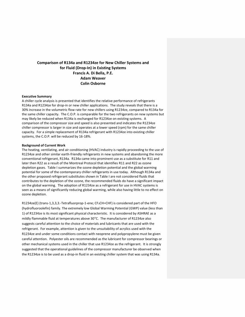
this comparison, the efficiency of the compressor is kept at the same value of 85% and
the diameter of the compressor impeller and speed are determined from a theoretical
Specific Speed (Ns) and Specific Diameter (Ds) notational analysis. The theoretical
compressor (Total-to-Static) adiabatic efficiency vs. Specific Speed is shown in Figure 1.
This theoretical presentation has been prepared by CN based on generic radial
compressor research and compares very favorably with independent, published
compressor analysis by others, as noted in Figure 1. This comparison is consistent with
the engineering task of designing a “new” chiller system that is specifically designed to
use R1234ze. The alternative solution is to use the existing R134a chiller hardware and
simply replace the R134a with the new fluid, R1234ze. The simple replacement of one
fluid with another in an installed and operating chiller system is often called a “Drop-In”
fluid application. This simple solution comes with a significant performance penalty as
the “old” R134a compressor impeller must now compress a different fluid; an inherently
less efficient compression process.
B. Determining the performance of a compressor using R1234ze, if it is used to replace the
R134a refrigerant, using the compressor components for which the chiller was initially
designed with R134a. In this study, the “old” R134a compressor speed and diameter are
not changed and a new Ns and Ds are calculated for the R1234ze refrigerant operating
at the necessary pressure ratios. The change in the refrigerant causes the “old” design
to not be the optimum for the R1234ze fluid as defined by the optimum Ns and Ds. This
ultimately effects the compressor efficiency and, depending on the severity of the
change in the C.O.P. due to the change in the compressor efficiency change, the
condenser heat exchanger size may also be undersized with the R1234ze. In this case,
the pressure ratio across the compressor may increase, which would also decrease the
C.O.P. for this “Drop-In” R1234ze application. However, it was determined from this
study that the small increase of 2-3% in heat transfer would not significantly change the
hot and cold temperature profiles in the condenser based on the engineering practice to
have considerable performance margins designed into the heat exchanger. The off-
design efficiency for the R1234ze fluid operation is determined by forcing the Ns and Ds
to change until the speed and diameter of the R1234ze compressor matches the “old”
R134a chiller compressor specifications. The new iterated value of Ns is then used with
Figure 1 to determine a rerate for the compressor efficiency. This new compressor
efficiency is then rerated based on the ratio of the “old” compressor diameter and what
the diameter of the compressor should be with the R1234ze. With the corrected
compressor efficiency now determined, the chiller cycle is recalculated.
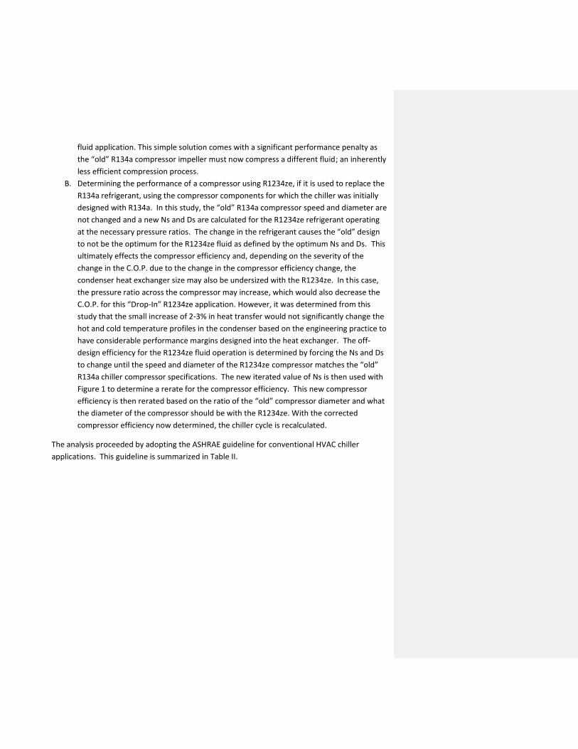
The analysis proceeded by adopting the ASHRAE guideline for conventional HVAC chiller
applications. This guideline is summarized in Table II.
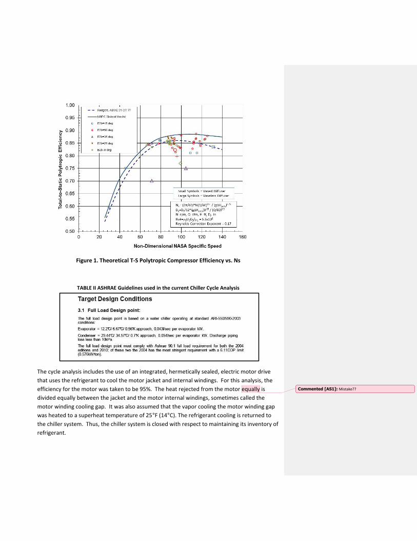
Figure 1. Theoretical T-S Polytropic Compressor Efficiency vs. Ns
TABLE II ASHRAE Guidelines used in the current Chiller Cycle Analysis
The cycle analysis includes the use of an integrated, hermetically sealed, electric motor drive
that uses the refrigerant to cool the motor jacket and internal windings. For this analysis, the
efficiency for the motor was taken to be 95%. The heat rejected from the motor equally is
divided equally between the jacket and the motor internal windings, sometimes called the
motor winding cooling gap. It was also assumed that the vapor cooling the motor winding gap
was heated to a superheat temperature of 25°F (14°C). The refrigerant cooling is returned to
the chiller system. Thus, the chiller system is closed with respect to maintaining its inventory of
refrigerant.
Commented [AS1]: Mistake??
Two chiller design configurations were analyzed with each fluid:
1. The basic or simple vapor compression refrigeration system that consists of four basic
components: a one-stage compressor, evaporator, condenser and throttle valve. This
cycle is diagrammed in Figure 2A.
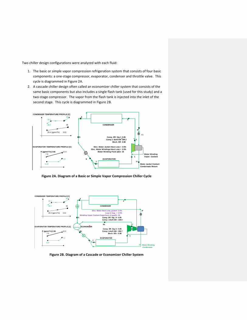
2. A cascade chiller design often called an economizer chiller system that consists of the
same basic components but also includes a single flash tank (used for this study) and a
two-stage compressor. The vapor from the flash tank is injected into the inlet of the
second stage. This cycle is diagrammed in Figure 2B.
Figure 2A. Diagram of a Basic or Simple Vapor Compression Chiller Cycle
Figure 2B. Diagram of a Cascade or Economizer Chiller System
CONDENSER TEMPERATURE PROFILE [C]
43 4
35.7 3
30.7 35 CONDENSER
4*
29.4 [gpm/rTn] 3.01
V1
5 Comp. Eff. Stg 1 0.85
Comp.1 shaft kW 199.2 2
Mech. Eff. 0.98
EVAPORATOR TEMPERATURE PROFILE [C] Elec. Motor Jacket Heat Loss = 2.5%
Elec. Motor Windings Heat Loss = 2.5%
[gpm/rTn] 2.66 12.0 Motor Winding Fluid ∆[F]= 25
7.0 Motor Winding
1 Vapor Coolant
7.0 6 EVAPORATOR
7 7*
5.97 Motor Jacket Coolant
Condensate Return
1 2 3 4 5 6 7 7*
P [bar,a] 3.60 9.05 9.05 9.04 9.04 3.62 3.62 3.62 COP)r= 6.58
T [C] 6.9 43.13 43.13 30.67 30.67 5.97 5.97 6.13 Motor Power [kWe]= 213.8
h [kJ/kG] 403.3 425.4 425.4 242.5 242.5 242.5 242.2 242.0 kWe/RT= 0.535
s [kJ/kG/K] 1.729 1.738 1.738 1.146 1.146 1.029 1.151 1.151 Qevap. [kWt]= 1406.5
density [kG/m3] 17.55 42.30 42.30 1186.26 1186.26 93.84 94.53 94.95 Qcond. [kWt]= -1614.1
Sat. Temp. [C] 6.0 35.89 35.89 35.83 35.83 6.13 6.1 6.13 Heat Balance Chk.: 99.6%
Quality (χ) 17.7% 17.5% 0
Flow [kG/s] 8.75 8.84 8.84 8.45 8.45 8.45 8.75 0.30 UA,evap[kWt/K]= 395
m3/s 0.50 0.21 0.21 0.01 0.01 0.09 0.09 0.00 UA,cond[kWt/K]= 439
Nm3/s 0.0072 0.0073 0.0073 0.0070 0.0070 0.0070 0.0072 0.0002CONDENSER TEMPERATURE PROFILE [C]
43 4
35.7 3
30.7 34 CONDENSER
Elec. Motor Heat Loss, jacket= 2.5% 4*
29.4 [gpm/rTn] 3.01 Loss in Gap = 2.5%
Winding Vapor Coolant Superheat ∆T,gap[F]= 25
5 Comp. Eff. Stg. 2= 0.85
Comp.1 shaft kW= 139.0
6a 2
EVAPORATOR TEMPERATURE PROFILE [C] ECONOMIZER
Comp. Eff. Stg 1= 0.85
[gpm/rTn] 2.66 12.0 6b Comp.1 shaft kW= 198.7
7.0 Mech. Eff.= 0.98
1
7.0 EVAPORATOR
7
5.97
7* Motor Winding
Condensate
1 2 3 4 5 6a 6b 7 Return
P [bar,a] 3.60 6.29 9.05 9.04 6.31 6.29 6.31 3.62 COP)r= 6.79
T [C] 7.0 28.14 43.06 30.67 23.36 23.29 23.36 5.97 Motor Power[kWe] 362.7
#Supercritical state (T>Tc, p>pc) h [kJ/kG] 403.3 416.3 425.3 242.5 242.5 411.4 232.0 231.8
s [kJ/kG/K] 1.729 1.733 1.737 1.146 1.147 1.717 1.111 1.114 Qevap. [kWt] 2461.3
density [kG/m3] 17.55 29.72 42.31 1186.26 373.25 30.58 1213.45 131.54 Qcond. [kWt] -2814.5
Sat. Temp. [C] 6.0 23.29 35.89 35.83 23.36 23.29 23.36 6.1 Heat Balance Chk.: 99.7%
Quality (χ) 6.0% 12.2%
Flow [kG/s] 14.39 15.42 15.42 14.76 14.76 0.88 13.885 14.39 UA,evap[kWt/K]= 692
m3/s 0.82 0.52 0.36 0.01 0.04 0.03 0.01 0.11 UA,cond[kWt/K]= 764
Nm3/s 0.0119 0.0127 0.0127 0.0122 0.0122 0.0007 0.0115 0.0119
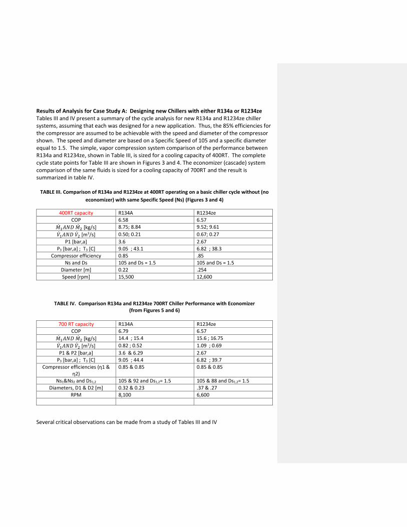
Results of Analysis for Case Study A: Designing new Chillers with either R134a or R1234ze Tables III and IV present a summary of the cycle analysis for new R134a and R1234ze chiller systems, assuming that each was designed for a new application. Thus, the 85% efficiencies for the compressor are assumed to be achievable with the speed and diameter of the compressor shown. The speed and diameter are based on a Specific Speed of 105 and a specific diameter equal to 1.5. The simple, vapor compression system comparison of the performance between R134a and R1234ze, shown in Table III, is sized for a cooling capacity of 400RT. The complete cycle state points for Table III are shown in Figures 3 and 4. The economizer (cascade) system comparison of the same fluids is sized for a cooling capacity of 700RT and the result is summarized in table IV.
TABLE III. Comparison of R134a and R1234ze at 400RT operating on a basic chiller cycle without (no
economizer) with same Specific Speed (Ns) (Figures 3 and 4)
400RT capacity R134A R1234ze
COP 6.58 6.57
�̇�1𝐴𝑁𝐷 �̇�2 [kg/s] 8.75; 8.84 9.52; 9.61
�̇�1𝐴𝑁𝐷 �̇�2 [m3/s] 0.50; 0.21 0.67; 0.27
P1 [bar,a] 3.6 2.67
P3 [bar,a] ; T3 [C] 9.05 ; 43.1 6.82 ; 38.3
Compressor efficiency 0.85 .85
Ns and Ds 105 and Ds = 1.5 105 and Ds = 1.5
Diameter [m] 0.22 .254
Speed [rpm] 15,500 12,600
TABLE IV. Comparison R134a and R1234ze 700RT Chiller Performance with Economizer
(from Figures 5 and 6)
700 RT capacity R134A R1234ze
COP 6.79 6.57
�̇�1𝐴𝑁𝐷 �̇�2 [kg/s] 14.4 ; 15.4 15.6 ; 16.75
�̇�1𝐴𝑁𝐷 �̇�2 [m3/s] 0.82 ; 0.52 1.09 ; 0.69
P1 & P2 [bar,a] 3.6 & 6.29 2.67
P3 [bar,a] ; T3 [C] 9.05 ; 44.4 6.82 ; 39.7
Compressor efficiencies (η1 & η2)
0.85 & 0.85 0.85 & 0.85
Ns1&Ns2 and Ds1,2 105 & 92 and Ds1,2= 1.5 105 & 88 and Ds1,2= 1.5
Diameters, D1 & D2 [m] 0.32 & 0.23 .37 & .27
RPM 8,100 6,600
Several critical observations can be made from a study of Tables III and IV
1. The C.O.P. for a simple vapor compression system, using R134a and R1234ze, is very
comparable.
2. The volume flow rate for the R1234ze system is 30-35% more than the R134a system for
the same capacity. The mass flow rate for the R1234ze system is 8-9% higher than the
mass flow rate for the R134a chiller.
3. The diameter for the R1234ze system compressor is 15% larger than the compressor
diameter for the R134a.
4. The speed for the r1234ze system compressor is 18-20% less than the r134a compressor
speed.
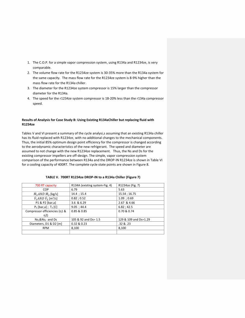
Results of Analysis for Case Study B: Using Existing R134aChiller but replacing fluid with R1234ze Tables V and VI present a summary of the cycle analysi,s assuming that an existing R134a chiller has its fluid replaced with R1234ze, with no additional changes to the mechanical components. Thus, the initial 85% optimum design point efficiency for the compressor is changed according to the aerodynamic characteristics of the new refrigerant. The speed and diameter are assumed to not change with the new R1234ze replacement. Thus, the Ns and Ds for the existing compressor impellers are off-design. The simple, vapor compression system comparison of the performance between R134a and the DROP-IN R1234ze is shown in Table VI for a cooling capacity of 400RT. The complete cycle state points are shown in Figure 8.
TABLE V. 700RT R1234ze DROP-IN to a R134a Chiller (Figure 7)
700 RT capacity R134A (existing system-Fig. 4) R1234ze (Fig. 7)
COP 6.79 5.63
�̇�1𝐴𝑁𝐷 �̇�2 [kg/s] 14.4 ; 15.4 15.54 ; 16.75
�̇�1𝐴𝑁𝐷 �̇�2 [m3/s] 0.82 ; 0.52 1.09 ; 0.69
P1 & P2 [bar,a] 3.6 & 6.29 2.67 & 4.66
P3 [bar,a] ; T3 [C] 9.05 ; 44.4 6.82 ; 42.5
Compressor efficiencies (η1 & η2)
0.85 & 0.85 0.70 & 0.74
Ns1&Ns2 and Ds 105 & 92 and Ds= 1.5 129 & 109 and Ds=1.29
Diameters, D1 & D2 [m] 0.32 & 0.23 .32 & .23
RPM 8,100 8,100
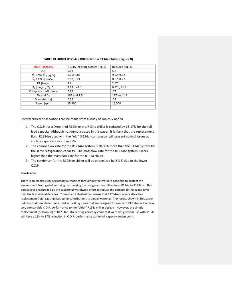
TABLE VI. 400RT R1234ze DROP-IN to a R134a Chiller (Figure 8)
400RT capacity R134A (existing System-Fig. 5) R1234ze (Fig. 8)
COP 6.58 5.7
�̇�1𝐴𝑁𝐷 �̇�2 [kg/s] 8.75; 8.84 9.52; 9.62
�̇�1𝐴𝑁𝐷 �̇�2 [m3/s] 0.50; 0.21 0.67; 0.27
P1 [bar,a] 3.6 2.67
P3 [bar,a] ; T3 [C] 9.05 ; 43.1 6.82 ; 41.4
Compressor efficiency 0.85 .74
Ns and Ds 105 and 1.5 127 and 1.3
Diameter [m] 0.22 .22
Speed [rpm] 15,500 15,500
Several critical observations can be made from a study of Tables V and VI
1. The C.O.P. for a Drop-In of R1234ze in a R134a chiller is reduced by 13-17% for the full-
load capacity. Although not demonstrated in this paper, it is likely that the replacement
fluid: R1234ze used with the “old” (R134a) compressor will present control issues at
cooling capacities less than 35%.
2. The volume flow rate for the R1234ze system is 30-35% more than the R134a system for
the same refrigeration capacity. The mass flow rate for the R1234ze system is 8-9%
higher than the mass flow rate for the R134a chiller.
3. The condenser for the R1234ze chiller will be undersized by 2-3 % due to the lower
C.O.P.
Conclusions There is an emphasis by regulatory authorities throughout the world to continue to protect the
environment from global warming by changing the refrigerant in chillers from R134a to R1234ze. This
objective is encouraged by the successful worldwide effort to reduce the damage to the ozone layer
over the last several decades. There is an industrial consensus that R1234ze is a very attractive
replacement fluid, causing little to no contributions to global warming. The results shown in this paper
indicate that new chiller units used in HVAC systems that are designed for use with R1234ze will achieve
very comparable C.O.P. performance to the “older” R134a chiller designs. However, the simple
replacement (or Drop-In) of R1234ze into existing chiller systems that were designed for use with R134a
will have a 13% to 17% reduction in C.O.P. performance at the full capacity design point.
Figure 3. R134a for 400RT with compressor efficiency = 85%
Figure 4. R1234ze 400 RT cycle with compressor efficiency = 85%
CONDENSER TEMPERATURE PROFILE [C]
43 4
35.7 3
30.7 35 CONDENSER
4*
29.4 [gpm/rTn] 3.01
V1
5 Comp. Eff. Stg 1 0.85
Comp.1 shaft kW 199.2 2
Mech. Eff. 0.98
EVAPORATOR TEMPERATURE PROFILE [C] Elec. Motor Jacket Heat Loss = 2.5%
Elec. Motor Windings Heat Loss = 2.5%
[gpm/rTn] 2.66 12.0 Motor Winding Fluid ∆[F]= 25
7.0 Motor Winding
1 Vapor Coolant
7.0 6 EVAPORATOR
7 7*
5.97 Motor Jacket Coolant
Condensate Return
1 2 3 4 5 6 7 7*
P [bar,a] 3.60 9.05 9.05 9.04 9.04 3.62 3.62 3.62 COP)r= 6.58
T [C] 6.9 43.13 43.13 30.67 30.67 5.97 5.97 6.13 Motor Power [kWe]= 213.8
h [kJ/kG] 403.3 425.4 425.4 242.5 242.5 242.5 242.2 242.0 kWe/RT= 0.535
s [kJ/kG/K] 1.729 1.738 1.738 1.146 1.146 1.029 1.151 1.151 Qevap. [kWt]= 1406.5
density [kG/m3] 17.55 42.30 42.30 1186.26 1186.26 93.84 94.53 94.95 Qcond. [kWt]= -1614.1
Sat. Temp. [C] 6.0 35.89 35.89 35.83 35.83 6.13 6.1 6.13 Heat Balance Chk.: 99.6%
Quality (χ) 17.7% 17.5% 0
Flow [kG/s] 8.75 8.84 8.84 8.45 8.45 8.45 8.75 0.30 UA,evap[kWt/K]= 395
m3/s 0.50 0.21 0.21 0.01 0.01 0.09 0.09 0.00 UA,cond[kWt/K]= 439
Nm3/s 0.0072 0.0073 0.0073 0.0070 0.0070 0.0070 0.0072 0.0002
CONDENSER TEMPERATURE PROFILE [C]
38 4
35.7 3
30.7 35 CONDENSER
4*
29.4 [gpm/rTn] 3.01
V1
5 Comp. Eff. Stg 1 0.85
Comp.1 shaft kW 199.5 2
Mech. Eff. 0.98
EVAPORATOR TEMPERATURE PROFILE [C] Elec. Motor Jacket Heat Loss = 2.5%
Elec. Motor Windings Heat Loss = 2.5%
[gpm/rTn] 2.66 12.0 Motor Winding Fluid ∆[F]= 25
7.0 Motor Winding
1 Vapor Coolant
6.9 6 EVAPORATOR
7 7*
5.97 Motor Jacket Coolant
Condensate Return
1 2 3 4 5 6 7 7*
P [bar,a] 2.67 6.82 6.82 6.80 6.70 2.68 2.68 2.68 COP)r= 6.57
T [C] 6.9 38.32 38.32 30.67 30.67 5.97 5.97 6.13 Motor Power [kWe]= 214.2
h [kJ/kG] 389.4 409.8 409.8 241.5 241.5 241.5 241.3 241.1 kWe/RT= 0.535
s [kJ/kG/K] 1.679 1.688 1.688 1.143 1.143 1.029 1.148 1.147 Qevap. [kWt]= 1406.5
density [kG/m3] 14.25 35.54 35.54 1145.24 1145.18 73.52 74.03 74.37 Qcond. [kWt]= -1614.0
Sat. Temp. [C] 6.0 35.91 35.91 35.83 35.28 6.13 6.1 6.13 Heat Balance Chk.: 99.6%
Quality (χ) 18.6% 18.4% 0
Flow [kG/s] 9.52 9.61 9.61 9.20 9.20 9.20 9.52 0.32 UA,evap[kWt/K]= 395
m3/s 0.67 0.27 0.27 0.01 0.01 0.13 0.13 0.00 UA,cond[kWt/K]= 454
Nm3/s 0.0081 0.0082 0.0082 0.0079 0.0079 0.0079 0.0081 0.0003
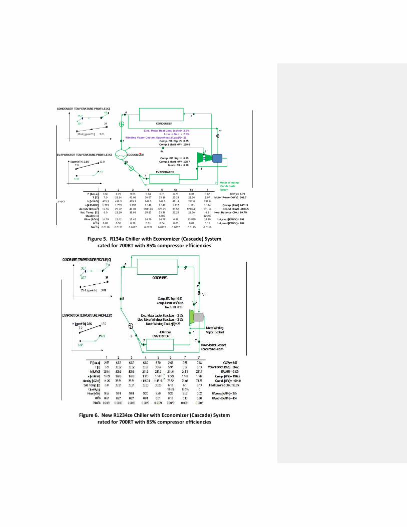
Figure 5. R134a Chiller with Economizer (Cascade) System rated for 700RT with 85% compressor efficiencies
Figure 6. New R1234ze Chiller with Economizer (Cascade) System rated for 700RT with 85% compressor efficiencies
CONDENSER TEMPERATURE PROFILE [C]
43 4
35.7 3
30.7 34 CONDENSER
Elec. Motor Heat Loss, jacket= 2.5% 4*
29.4 [gpm/rTn] 3.01 Loss in Gap = 2.5%
Winding Vapor Coolant Superheat ∆T,gap[F]= 25
5 Comp. Eff. Stg. 2= 0.85
Comp.1 shaft kW= 139.0
6a 2
EVAPORATOR TEMPERATURE PROFILE [C] ECONOMIZER
Comp. Eff. Stg 1= 0.85
[gpm/rTn] 2.66 12.0 6b Comp.1 shaft kW= 198.7
7.0 Mech. Eff.= 0.98
1
7.0 EVAPORATOR
7
5.97
7* Motor Winding
Condensate
1 2 3 4 5 6a 6b 7 Return
P [bar,a] 3.60 6.29 9.05 9.04 6.31 6.29 6.31 3.62 COP)r= 6.79
T [C] 7.0 28.14 43.06 30.67 23.36 23.29 23.36 5.97 Motor Power[kWe] 362.7
#Supercritical state (T>Tc, p>pc) h [kJ/kG] 403.3 416.3 425.3 242.5 242.5 411.4 232.0 231.8
s [kJ/kG/K] 1.729 1.733 1.737 1.146 1.147 1.717 1.111 1.114 Qevap. [kWt] 2461.3
density [kG/m3] 17.55 29.72 42.31 1186.26 373.25 30.58 1213.45 131.54 Qcond. [kWt] -2814.5
Sat. Temp. [C] 6.0 23.29 35.89 35.83 23.36 23.29 23.36 6.1 Heat Balance Chk.: 99.7%
Quality (χ) 6.0% 12.2%
Flow [kG/s] 14.39 15.42 15.42 14.76 14.76 0.88 13.885 14.39 UA,evap[kWt/K]= 692
m3/s 0.82 0.52 0.36 0.01 0.04 0.03 0.01 0.11 UA,cond[kWt/K]= 764
Nm3/s 0.0119 0.0127 0.0127 0.0122 0.0122 0.0007 0.0115 0.0119
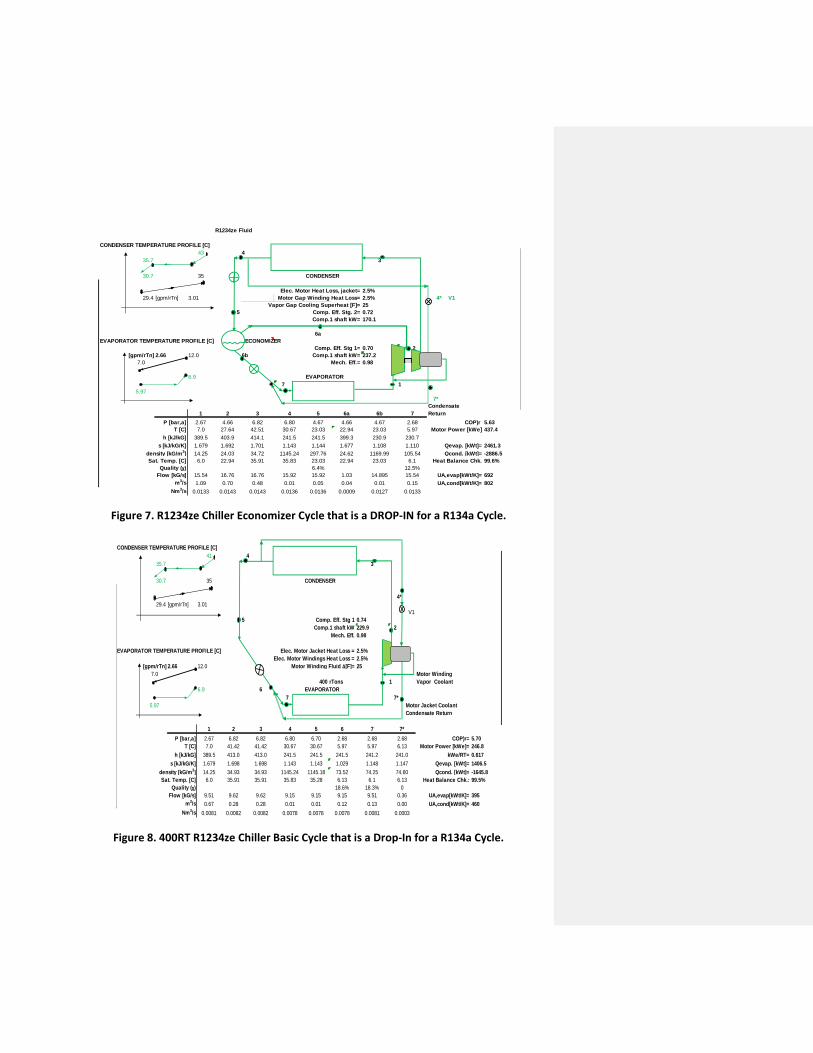
Figure 7. R1234ze Chiller Economizer Cycle that is a DROP-IN for a R134a Cycle.
Figure 8. 400RT R1234ze Chiller Basic Cycle that is a Drop-In for a R134a Cycle.
R1234ze Fluid
CONDENSER TEMPERATURE PROFILE [C]
43 4
35.7 3
30.7 35 CONDENSER
Elec. Motor Heat Loss, jacket= 2.5%
29.4 [gpm/rTn] 3.01 Motor Gap Winding Heat Loss= 2.5% 4* V1
Vapor Gap Cooling Superheat [F]= 25
5 Comp. Eff. Stg. 2= 0.72
Comp.1 shaft kW= 170.1
6a
EVAPORATOR TEMPERATURE PROFILE [C] ECONOMIZER
Comp. Eff. Stg 1= 0.70 2
[gpm/rTn] 2.66 12.0 6b Comp.1 shaft kW= 237.2
7.0 Mech. Eff.= 0.98
6.9 EVAPORATOR
7 1
5.97
7*
Condensate
1 2 3 4 5 6a 6b 7 Return
P [bar,a] 2.67 4.66 6.82 6.80 4.67 4.66 4.67 2.68 COP)r 5.63
T [C] 7.0 27.64 42.51 30.67 23.03 22.94 23.03 5.97 Motor Power [kWe] 437.4
h [kJ/kG] 389.5 403.9 414.1 241.5 241.5 399.3 230.9 230.7
s [kJ/kG/K] 1.679 1.692 1.701 1.143 1.144 1.677 1.108 1.110 Qevap. [kWt]= 2461.3
density [kG/m3] 14.25 24.03 34.72 1145.24 297.76 24.62 1169.99 105.54 Qcond. [kWt]= -2886.5
Sat. Temp. [C] 6.0 22.94 35.91 35.83 23.03 22.94 23.03 6.1 Heat Balance Chk. 99.6%
Quality (χ) 6.4% 12.5%
Flow [kG/s] 15.54 16.76 16.76 15.92 15.92 1.03 14.895 15.54 UA,evap[kWt/K]= 692
m3/s 1.09 0.70 0.48 0.01 0.05 0.04 0.01 0.15 UA,cond[kWt/K]= 802
Nm3/s 0.0133 0.0143 0.0143 0.0136 0.0136 0.0009 0.0127 0.0133
CONDENSER TEMPERATURE PROFILE [C]
41 4
35.7 3
30.7 35 CONDENSER
4*
29.4 [gpm/rTn] 3.01
V1
5 Comp. Eff. Stg 1 0.74
Comp.1 shaft kW 229.9 2
Mech. Eff. 0.98
EVAPORATOR TEMPERATURE PROFILE [C] Elec. Motor Jacket Heat Loss = 2.5%
Elec. Motor Windings Heat Loss = 2.5%
[gpm/rTn] 2.66 12.0 Motor Winding Fluid ∆[F]= 25
7.0 Motor Winding
400 rTons 1 Vapor Coolant
6.9 6 EVAPORATOR
7 7*
5.97 Motor Jacket Coolant
Condensate Return
1 2 3 4 5 6 7 7*
P [bar,a] 2.67 6.82 6.82 6.80 6.70 2.68 2.68 2.68 COP)r= 5.70
T [C] 7.0 41.42 41.42 30.67 30.67 5.97 5.97 6.13 Motor Power [kWe]= 246.8
h [kJ/kG] 389.5 413.0 413.0 241.5 241.5 241.5 241.2 241.0 kWe/RT= 0.617
s [kJ/kG/K] 1.679 1.698 1.698 1.143 1.143 1.029 1.148 1.147 Qevap. [kWt]= 1406.5
density [kG/m3] 14.25 34.93 34.93 1145.24 1145.18 73.52 74.25 74.60 Qcond. [kWt]= -1645.8
Sat. Temp. [C] 6.0 35.91 35.91 35.83 35.28 6.13 6.1 6.13 Heat Balance Chk.: 99.5%
Quality (χ) 18.6% 18.3% 0
Flow [kG/s] 9.51 9.62 9.62 9.15 9.15 9.15 9.51 0.36 UA,evap[kWt/K]= 395
m3/s 0.67 0.28 0.28 0.01 0.01 0.12 0.13 0.00 UA,cond[kWt/K]= 460
Nm3/s 0.0081 0.0082 0.0082 0.0078 0.0078 0.0078 0.0081 0.0003