comparison of commercial plasma probe systems
TRANSCRIPT
COMPARISON OF COMMERCIAL
PLASMA PROBE SYSTEMS
V. A. Godyak B. M. Alexandrovich RF Plasma Consulting Plasma Sensors
[email protected] [email protected]
AVS 61th International Symposium & Exhibition
November 10-14, 2014, Baltimore, Maryland
1

2
Today, plasma simulation codes are practically the main tool in
studying plasma electrodynamics, plasma transport and plasma
kinetics in industrial plasma sources. These codes applied to
complicated processing gas mixture are sometime missing many
cross sections for variety of plasma-chemical reactions.
They also are missing effects of nonlocal and nonlinear plasma
electrodynamics that has been proved important and even dominant
in rf plasmas at low gas pressure.
In such situation, a reliable measurement of the plasma parameters
would give a valuable experimental data for understanding variety
of electrodynamics, transport and kinetic process in such plasmas
and for validation of existing theoretical models and numerical
codes.
Introduction
Probe diagnostics is ideally suited for measurement in plasma
processing reactors (providing it done professionally)
“There is no plasma diagnostics method other than probe
diagnostics where the danger of incorrect measurements
and erroneous interpretation of results are so great.”
L. Schott, in Plasma Diagnostics, editor
W. Lochte-Holtgreven, Amsterdam,1968
It was true then, it is even more true today, when plasmas
are more complicated and the measurements are more
sophisticated. Still, technical limitations of many
contemporary commercial probe systems may lead to
significant errors
3
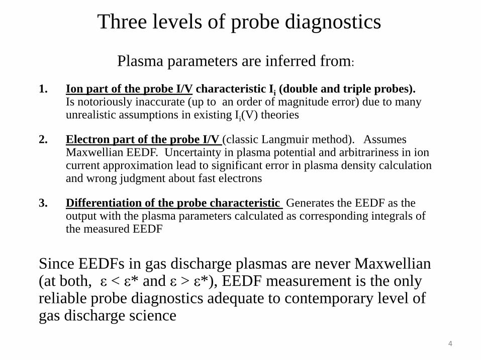
Three levels of probe diagnostics
Plasma parameters are inferred from:
1. Ion part of the probe I/V characteristic Ii (double and triple probes). Is notoriously inaccurate (up to an order of magnitude error) due to many unrealistic assumptions in existing Ii(V) theories
2. Electron part of the probe I/V (classic Langmuir method). Assumes Maxwellian EEDF. Uncertainty in plasma potential and arbitrariness in ion current approximation lead to significant error in plasma density calculation and wrong judgment about fast electrons
3. Differentiation of the probe characteristic Generates the EEDF as the output with the plasma parameters calculated as corresponding integrals of the measured EEDF
Since EEDFs in gas discharge plasmas are never Maxwellian (at both, ε < ε* and ε > ε*), EEDF measurement is the only reliable probe diagnostics adequate to contemporary level of gas discharge science
4
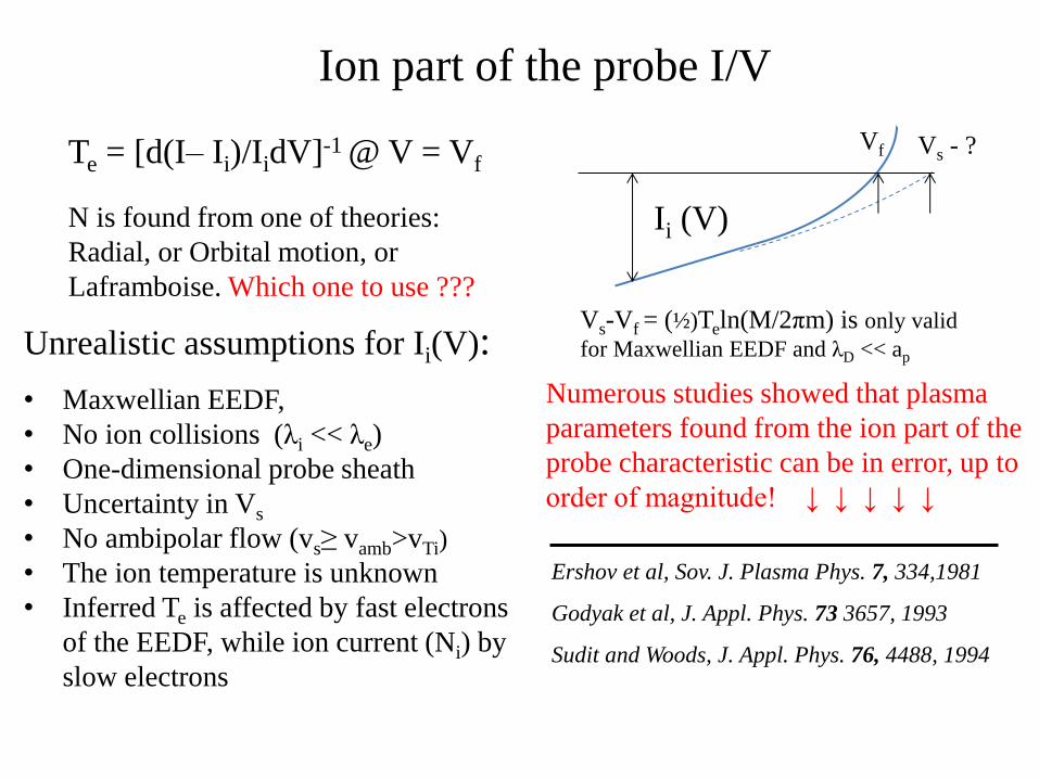
Ion part of the probe I/V
Vs - ? Vf Te = [d(I– Ii)/IidV]-1 @ V = Vf
N is found from one of theories:
Radial, or Orbital motion, or
Laframboise. Which one to use ???
Ii (V)
Unrealistic assumptions for Ii(V):
• Maxwellian EEDF,
• No ion collisions (λi << λe)
• One-dimensional probe sheath
• Uncertainty in Vs
• No ambipolar flow (vs≥ vamb>vTi)
• The ion temperature is unknown
• Inferred Te is affected by fast electrons
of the EEDF, while ion current (Ni) by
slow electrons
Numerous studies showed that plasma
parameters found from the ion part of the
probe characteristic can be in error, up to
order of magnitude! ↓ ↓ ↓ ↓ ↓
Ershov et al, Sov. J. Plasma Phys. 7, 334,1981
Godyak et al, J. Appl. Phys. 73 3657, 1993
Sudit and Woods, J. Appl. Phys. 76, 4488, 1994
Vs-Vf = (½)Teln(M/2πm) is only valid
for Maxwellian EEDF and λD << ap
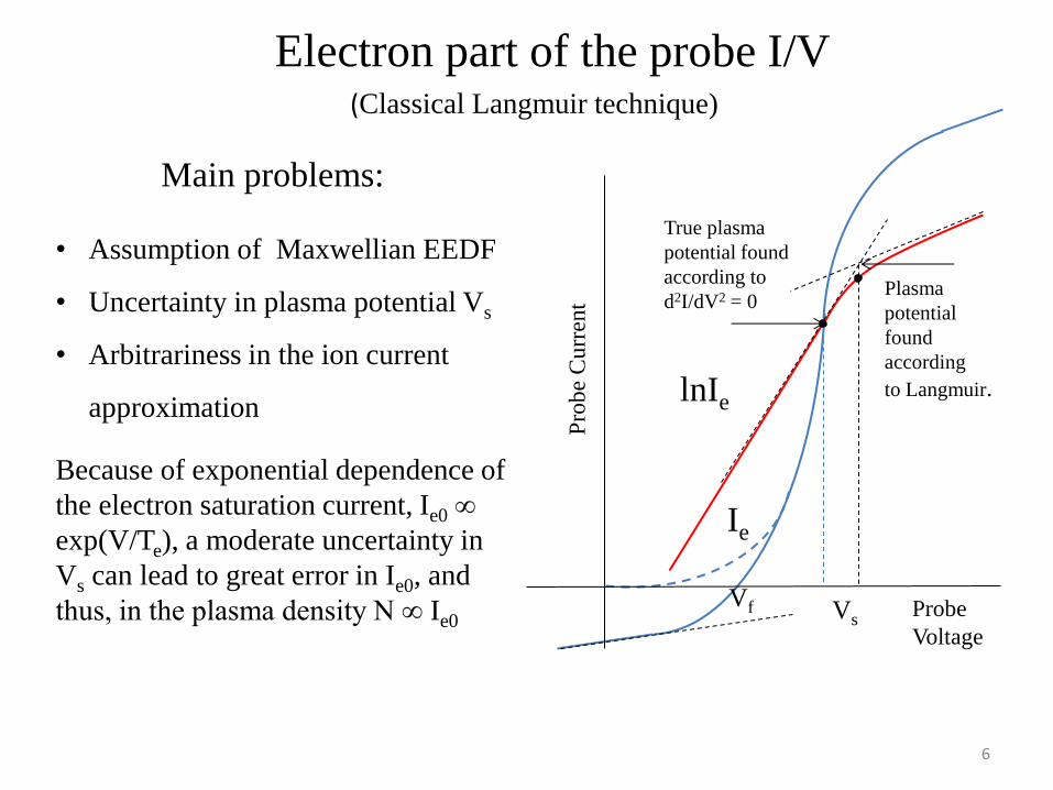
Electron part of the probe I/V
Probe
Voltage
Ie
lnIe
Plasma
potential
found
according
to Langmuir.
Vs
Vf
True plasma
potential found
according to
d2I/dV2 = 0
Pro
be
Cu
rren
t
(Classical Langmuir technique)
Main problems:
• Assumption of Maxwellian EEDF
• Uncertainty in plasma potential Vs
• Arbitrariness in the ion current
approximation
Because of exponential dependence of
the electron saturation current, Ie0 ∞
exp(V/Te), a moderate uncertainty in
Vs can lead to great error in Ie0, and
thus, in the plasma density N ∞ Ie0
6
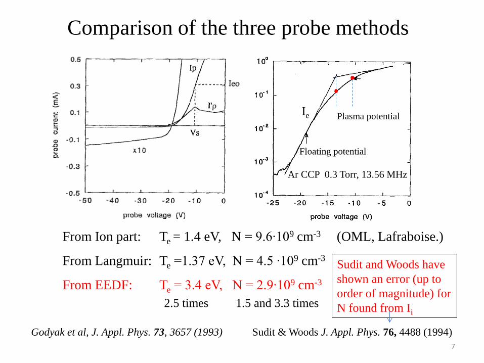
Comparison of the three probe methods
From Ion part: Te = 1.4 eV, N = 9.6∙109 cm-3 (OML, Lafraboise.)
From Langmuir: Te =1.37 eV, N = 4.5 ∙109 cm-3
From EEDF: Te = 3.4 eV, N = 2.9∙109 cm-3
2.5 times 1.5 and 3.3 times
Floating potential
Ar CCP 0.3 Torr, 13.56 MHz
Ie Plasma potential
Sudit and Woods have
shown an error (up to
order of magnitude) for
N found from Ii
Godyak et al, J. Appl. Phys. 73, 3657 (1993) Sudit & Woods J. Appl. Phys. 76, 4488 (1994)
7
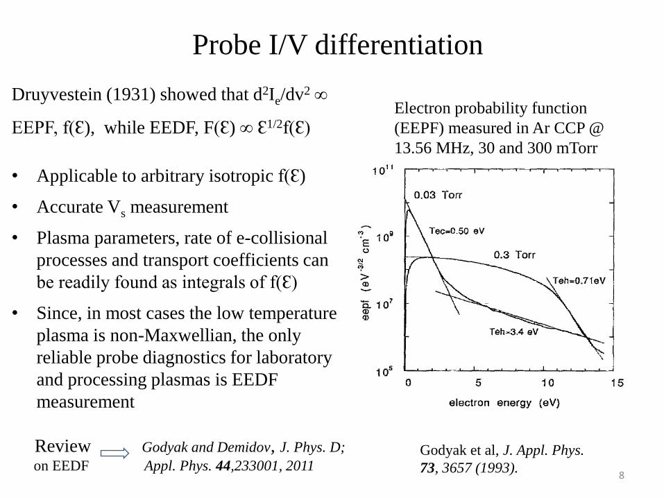
Probe I/V differentiation
Druyvestein (1931) showed that d2Ie/dv2 ∞
EEPF, f(Ɛ), while EEDF, F(Ɛ) ∞ Ɛ1/2f(Ɛ)
• Applicable to arbitrary isotropic f(Ɛ)
• Accurate Vs measurement
• Plasma parameters, rate of e-collisional
processes and transport coefficients can
be readily found as integrals of f(Ɛ)
• Since, in most cases the low temperature
plasma is non-Maxwellian, the only
reliable probe diagnostics for laboratory
and processing plasmas is EEDF
measurement
Review Godyak and Demidov, J. Phys. D;
on EEDF Appl. Phys. 44,233001, 2011
Electron probability function
(EEPF) measured in Ar CCP @
13.56 MHz, 30 and 300 mTorr
Godyak et al, J. Appl. Phys.
73, 3657 (1993). 8

Popular commercial probe systems on the market
“The Langmuir Probe™ is
by far the best commercial
Langmuir Probe on the
market,…” ; “…is the
fastest* and most reliable
Langmuir probe in the world
(time resolution 12.5 ns*)”.
ALP, Impedans (Ireland) ESPion, Hiden (UK) MFPA, Plasma Sensors (USA)
“ESPion has the highest
blocking impedance of any
commercially available unit-
4.25 MOhm at 13.56 MHz*…”
“ESPION has more than x10*
the resolution of other
commercial Langmuir probes.”
“Able to measure and display
the true EEDF in the real
time”;“…unique state-of-the-
art features unavailable in any
other commercial products”.
• *Highlighted features and numbers may mislead users (acquisition rate does not define the
time response of the probe system, inductive impedance of the probe filter does not define
RF rejection ratio)
• Because of poorly defined parameters of probe systems it is hard to compare them based
on specifications alone
• Indeed, ALP and ESPion have similar characteristics, and both differs from MFPA’s
• Superior performance of a particular probe system can be proven only by comparing the
data quality obtained by similar instruments. 9
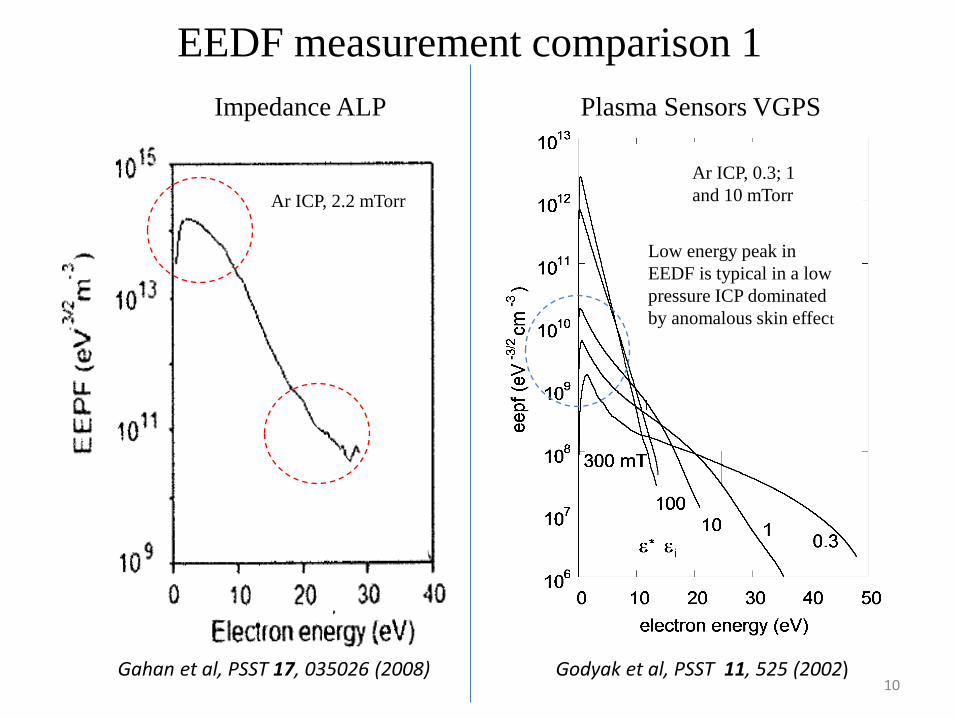
Ar ICP, 2.2 mTorr
Impedance ALP
Gahan et al, PSST 17, 035026 (2008) Godyak et al, PSST 11, 525 (2002)
Ar ICP, 0.3; 1
and 10 mTorr
Low energy peak in
EEDF is typical in a low
pressure ICP dominated
by anomalous skin effect
Plasma Sensors VGPS
EEDF measurement comparison 1
10
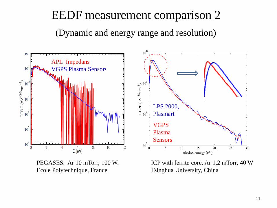
APL Impedans
VGPS Plasma Sensors
PEGASES. Ar 10 mTorr, 100 W.
Ecole Polytechnique, France
LPS 2000,
Plasmart
VGPS
Plasma
Sensors
ICP with ferrite core. Ar 1.2 mTorr, 40 W
Tsinghua University, China
EEDF measurement comparison 2
(Dynamic and energy range and resolution)
11

Argon, 20 mTorr
Hiden: emax = 7-11 eV
Argon, 20 mTorr
Pl. Sen.: emax = 15-22 eV
Distorted @ low energy and lost
information @ high energy
“Maxwellization”
νee ∞ NTe-3/2
“Druyvesteynization”
Comparison of EEPF measured
with different commercial probe
stations, Espion of Hiden and
VGPS of Plasma Sensors
At maximal discharge power of
2 kW, N ≈ 1·1012 cm-3, thus the
EEPF @ ε < ε* has to be a
Maxwellian one
“Druyvesteynization” effect is
found in many publications of
EEDF measurements made with
home-made and commercial
probe systems
EEDF measurements in a commercial ICP reactor
V. Godyak et al, GEC 2009,
Saratoga Springs, NY, USA
Ɛ*
12

Measuring of EEDF in reactors with processing gases
Wide specter and large amplitude of rf plasma potential, low-frequency noise, high
rate of probe contamination and bad plasma contact to the grounded chamber are the
major problems making difficult probe diagnostics there
Measurement in the same ICP reactor. Oxygen 10 mTorr
Plasma Sensors Hiden
13

MFPA Display
14
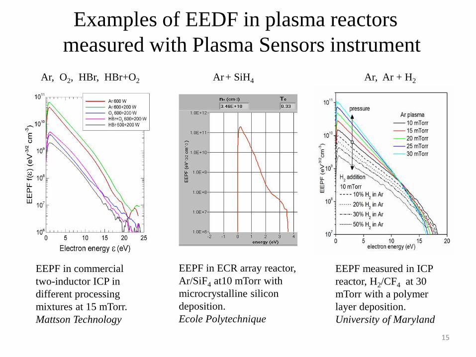
Examples of EEDF in plasma reactors
measured with Plasma Sensors instrument
Ar, O2, HBr, HBr+O2 Ar + SiH4 Ar, Ar + H2
EEPF measured in ICP
reactor, H2/CF4 at 30
mTorr with a polymer
layer deposition.
University of Maryland
EEPF in ECR array reactor,
Ar/SiF4 at10 mTorr with
microcrystalline silicon
deposition.
Ecole Polytechnique
EEPF in commercial
two-inductor ICP in
different processing
mixtures at 15 mTorr.
Mattson Technology
15
40 µS 70 µS 40 µS 90 µS 120 µS 150 µS 180 µS 220 µS
106
107
108
109
1010
0 5 10 15 20 25 30
eep
f (e
V 3
/2cm
-3)
energy (eV)
Ar 10 mTorr
Id = 3 A
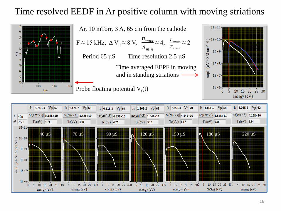
Time resolved EEDF in Ar positive column with moving striations
Probe floating potential Vf(t)
Ar, 10 mTorr, 3 A, 65 cm from the cathode
F ≈ 15 kHz, Δ Vp ≈ 8 V, 𝑛𝑚𝑎𝑥
𝑛𝑚𝑖𝑛
≈ 4, 𝑇𝑒𝑚𝑎𝑥
𝑇𝑒𝑚𝑖𝑛
≈ 2
Period 65 µS Time resolution 2.5 µS
Time averaged EEPF in moving
and in standing striations
16

Conclusions
Acknowledgments
The authors thanks their colleagues for sharing results of EEDF measurements
The work was supported in part by the DOE OFES (Contract No DE-SC0001939)
• EEDF measurement is only reliable probe diagnostics providing accurate plasma
parameters, rates of plasma-chemical processes and transport coefficients
• Design of EEDF measurement arrangement requires professional skill in analog and
digital electronics and deep knowledge of gas discharge physics
• Majority of commercial probe instruments unable to accurately measure of EEDF
having too low both, energy resolution and dynamic range of EEDF measurement
• The problems in EEDF measurement and remedies to overcome them are given in Topical Review by Godyak & Demidov J. Phys. D: Appl. Phys. 44 (2011) 233001 (30pp)
17