comparison between eurocode 8 and rsa/rebap - ulisboa · comparison between eurocode 8 and...
TRANSCRIPT
Comparison between Eurocode 8 and RSA/REBAP Seismic design of reinforced concrete structures
Hugo Pereira Lopes Instituto Superior Técnico, Lisboa, Portugal
Abstract
Considering that the seismic action is a phenomenon whose effect in structures can be quite significant, it is of the utmost importance that the design of structures must be performed in the best possible way to take into account these effects, aiming for an adequate structural response.
In this context, the EC8, a new European standard for the seismic design of structures, will replace the current nationally set regulations (RSA/REBAP) with more detailed and accurate rules to take into account the effect of the seismic action. The aim of the present work is to study the presented aspects of the new EC8 code and compare them with the current RSA/REBAP codes.
The work herein presented is divided in two parts. In the first part the main aspects of the EC8 are described, discussed and compared with the current national codes, namely: the definition of the response spectra, the seismic zones in the national territory and the design demands required for the design of beams, columns and walls, taking into account the approach made in the EC8 code to the design philosophy. On the second part of the current work, a case study is presented and the different considerations of analysis and design proposed in the EC8 and in the RSA/REBAP codes are applied. Especially attention is devoted to the design of beams, columns and walls, where the different results obtained are compared.
Key-words: EC8, RSA, REBAP, design, beams, columns, walls 1. Introduction
Nowadays, there one no doubts that the seismic action appears as an action to consider in the design of the structures, which effect will depend on the seismicity where the structure is located.
In order to accurately define and consider in the most appropriate way the effect of the seismic action, there is Eurocode 8 [EN 1998, 2004], that it appears as an European code to regulate the design of structures for earthquake resistance, and which comes to substitute the actual codes that are applied at national level, namely RSA [2005] and REBAP [2004], that had been defined to more than twenty years, and actually they do need to be replaced.
Thus, we are facing a transition period between codes, being essential to understand the application of this new regulation and all their considerations, as well as to verify the main differences with the national codes. It is in this perspective that this work is framed, trying, in a clear and rigorous way, to evidence the existent differences between regulations, especially because, in spite of they regulate, in both cases, the seismic design of structures, they present significant differences, namely, in philosophy of design; the “Capacity Design” procedure is only adopted by EC8.
Consequently, this work starts (Section 2) by presenting the EC8, namely, what regards the design of reinforced concrete buildings, settling simultaneously, a comparison with the defined in the actual codes, RSA / REBAP.
This comparison between codes focuses on several aspects: initially the definition of the seismic action, namely, the seismic zones of the territory and the definition of the response spectrum is tackled. Then the principles of the “Capacity Design” procedure are presented. Finally, the design of reinforced concrete structures, including the definition of the behaviour factor, as well as the conditions and demands presented in the codes that allow the design of the several structural elements are also described.
After this description and comparison of codes, a case study is presented (section 3), where the different codes are applied to a RC building. First, the results obtained by means of different modal response analyses (EC8 and RSA) – linear dynamic analyses – are compared. Then different structural elements (a column, the adjacent beams and a wall) are designed according to the different codes (EC8 and REBAP) and the longitudinal and transversal reinforcement compared and discussed. Email address: [email protected] September 28, 2007
1
2. Comparison between EC8 and RSA/REBAP
In this section a comparison study between codes (EC8 and RSA/REBAP) are presented.
2.1. Definition of Seismic Action
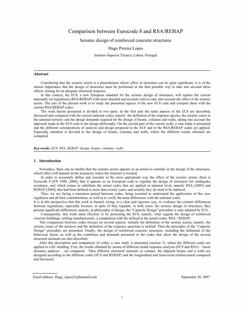
Regarding the seismic zones definition of the national territory, significant differences appear in what concerns the proposed in the national annex of EC8. The following figures show the different seismic areas as defined in actual version of national annex of EC8 and in RSA:
Zonas
1
2
3
3
Zonas
2 1
4 5
Figure 2 – Seismic zones according to RSA [RSA, 2005]
Figure 1 – Seismic Zones according to EC8 [LNEC, 2006]
Analyzing the two different seismic risk distributions, it is possible to confirm that EC8 presents different seismic zones according to the seismic action considered. In RSA, there is only one seismic zone distribution, independently of the type of earthquake considered.
Moreover, for both types of seismic action, the area of the national territory that corresponds to a larger seismic risk (area in red / area A), decreases significantly in EC8. However, it does not mean that EC8 is less severe, as shown in the following. For the new seismic action definition it is assumed that the response spectrum values are significantly higher in Algarve, thus more restricted areas were defined. The consequences of this new seismic zone distribution will be better understood when the response spectra proposed by both codes are compared.
Regarding the ground type characterization, the EC8 considers 7 different types of soil, instead of RSA that establishes
only 3 types of land conditions. This new classification leads to a more exact and coherent definition of the soil conditions, leading to significant differences in what concerns the response spectrum values proposed by the EC8 and RSA.
The seismic action definition according to EC8 is based on two spectrum configurations. In the national annex of EC8
a spectrum type 1 is defined for earthquakes with a magnitude higher than 7.0 and a spectrum type 2 for the remain cases. RSA also presents two types of seismic actions, namely, moderate magnitude at small focal distance earthquakes (seismic action type 1) and earthquakes of higher magnitude values and for a larger focal distance (seismic action type 2). Nevertheless, the designations of the two types of spectrum in the two codes are opposite, i.e. the seismic action type 1 of RSA corresponds to the spectrum type 2 of EC8 and vice-versa.
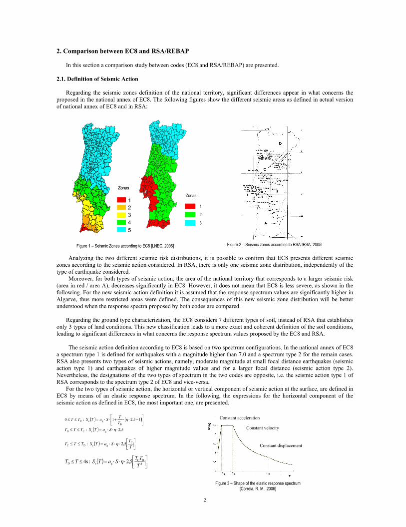
For the two types of seismic action, the horizontal or vertical component of seismic action at the surface, are defined in EC8 by means of an elastic response spectrum. In the following, the expressions for the horizontal component of the seismic action as defined in EC8, the most important one, are presented.
( ) ( ⎥⎦
⎤⎢⎣
⎡−⋅⋅+⋅⋅=≤≤ 15,21 :0
Bge η
TTSaTSTT B )
( ) 5,2 : geCB ⋅⋅⋅=≤≤ ηSaTSTTT
( ) ⎥⎦
⎤⎢⎣
⎡⋅⋅⋅=≤≤
TT
SaTSTTT CgeDC 5,2 : η
( ) ⎥⎦⎤
⎢⎣⎡⋅⋅⋅=≤≤ 2
DCgeD 5,2 :s4
TTTSaTSTT η
Figure 3 – Shape of the elastic response spectrum [Correia, R. M., 2006]
Constant acceleration Constant velocity
Constant displacement
2
• Se(T) elastic response sepctrum;
• T period of vibration;
• ag design ground acceleration on rock ground type;
• TB lower limit of the period of the constant spectral acceleration branch;
• TC upper limit of the period of the constant spectral acceleration branch;
• TD value that define the beginning of the constant displacement response range of the spectrum;
• S soil factor;
• η damping correction factor ( η = 1 to a damping of 5% );
• The parameters ag, TB, TC, TD e S are defined in National Annex.
The values of mentioned variables, as proposed in the national annex of EC8 , for ag, TB, TC, TD and S and rock soils (for other ground types these values are not still completely defined) are presented in Tables 1 and 2. Table 3 presents the values for the response spectrum definition for RSA.
ag (cm/s 2 ) S TB (s) TC (s) TD (s)Zone 1 250Zone 2 200Zone 3 150Zone 4 100Zone 5 50
1,0 2,00
EC8 - Distant Seismic Action
0,10 0,60
ag (cm/s 2 ) S TB (s) TC (s) TD (s)Zone 1 170Zone 2 110Zone 3 80
0,25 2,001,0 0,10
EC8 - Near Seismic Action
Tables 1 and 2 – Spectrum parameters presented in National Annex of EC8, for rock ground type
Near Distant
Zones ag (cm/s2) ag (cm/s2)Zone A 107 177Zone B 75 124Zone C 54 89Zone D 32 53
Seismic ActionRSA
Table 3 – Ground acceleration according to RSA
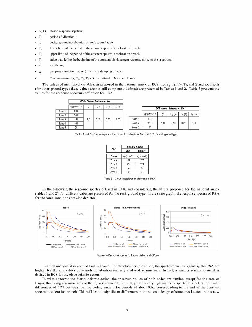
In the following the response spectra defined in EC8, and considering the values proposed for the national annex
(tables 1 and 2), for different cities are presented for the rock ground type. In the same graphs the response spectra of RSA for the same conditions are also depicted.
Lagos
0
200
400
600
800
0,00 0,50 1,00 1,50 2,00 2,50 3,00
Períod (s)
Acce
lerat
ion (c
m/s
^2)
EC8 Dist - zone 1 RSAx1,5 Dist - zone AEC8 Near - zone 1 RSAx1,5 Near - zone A
%5=ξ
Lisboa / V.R.S.António / Sines
0
200
400
600
800
0,00 0,50 1,00 1,50 2,00 2,50 3,00
Períod (s)
Acce
lerat
ion (c
m/s
^2)
EC8 Dist - zone 3 RSAx1,5 Dist - zone AEC8 Near - zone 1 RSAx1,5 Near - zone A
%5=ξ
Porto / Bragança
0
200
400
600
800
0,00 0,50 1,00 1,50 2,00 2,50 3,00Períod (s)
Acce
lerati
on (c
m/s^
2)
EC8 Dist - zone 5 RSAx1,5 Dist - zone DEC8 Near - zone 3 RSAx1,5 Near - zone D
%5=ξ
Figure 4 – Response spectra for Lagos, Lisbon and OPorto
In a first analysis, it is verified that in general, for the close seismic action, the spectrum values regarding the RSA are higher, for the any values of periods of vibration and any analyzed seismic area. In fact, a smaller seismic demand is defined in EC8 for the close seismic action.
In what concerns the distant seismic action, the spectrum values of both codes are similar, except for the area of Lagos, that being a seismic area of the highest seismicity in EC8, presents very high values of spectrum accelerations, with differences of 50% between the two codes, namely for periods of about 0.6s, corresponding to the end of the constant spectral acceleration branch. This will lead to significant differences in the seismic design of structures located in this new
3
seismic area. The same does happen for different ground conditions, where the EC8 spectrum values penalize the seismic design of
structures. As the soil becomes softer, the accelerations response spectrum values are always higher than the ones proposed in RSA (see Figure 5).
Distant Seismic Action - Lagos
0
200
400
600
800
1000
0,00 0,50 1,00 1,50 2,00 2,50 3,00
Period (s)Ac
celer
ation
(cm/
s^2
Ground A
Ground BGround C
Ground D
Ground E
RSA - Ground IRSA - Ground II
RSA - Ground III
%5=ξ
Figure 5 – Response spectra to Lagos, for several ground
types
This clear aggravation is due to the larger amplification of the seismic vibrations in softer soils (Sousa J., 2004). Thus
the seismic design of structures founded in soft soil, have to be quite rigorous. This is an aspect that RSA does not take into account, on the contrary, it associates to softer soils, smaller spectrum acceleration values than for the soils of larger rigidity.
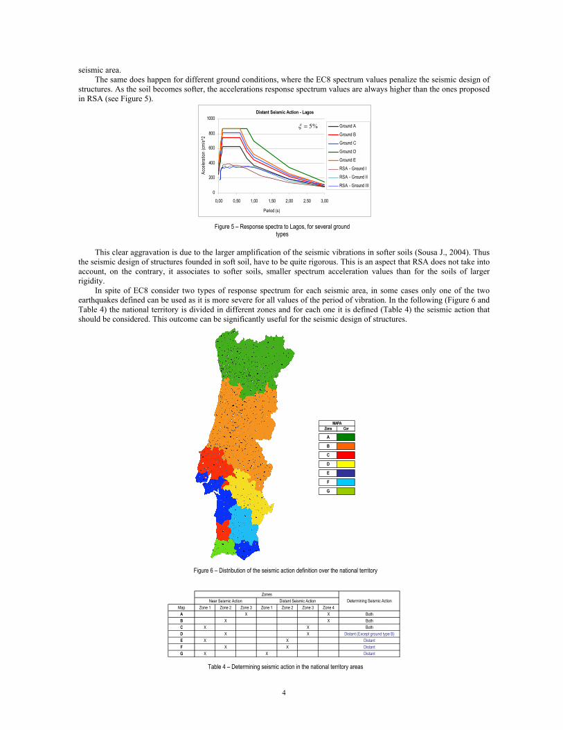
In spite of EC8 consider two types of response spectrum for each seismic area, in some cases only one of the two earthquakes defined can be used as it is more severe for all values of the period of vibration. In the following (Figure 6 and Table 4) the national territory is divided in different zones and for each one it is defined (Table 4) the seismic action that should be considered. This outcome can be significantly useful for the seismic design of structures.
Zona Cor
A
B
C
D
E
F
G
MAPA
Figure 6 – Distribution of the seismic action definition over the national territory
Map Zone 1 Zone 2 Zone 3 Zone 1 Zone 2 Zone 3 Zone 4A X XB X XC X XD X X Distant (Except ground type B)E X X DistantF X X DistantG X X Distant
Determining Seismic ActionNear Seismic Action Distant Seismic ActionZones
BothBothBoth
Table 4 – Determining seismic action in the national territory areas
4
2.2. Capacity Design The “Capacity Design” philosophy, adopted in EC8, forces the structures to be designed to have localized plastic
behaviour, where an appropriate level of damage is accepted, and elastic behaviour in the remaining part, where no damage takes place. The regions where plastic behaviour is supposed to occur are either plastic hinges or other types of local plastic zones. Most often, these are selected with respect to their ability of developing ductile behaviour and accessibility to repairing work after the earthquake event. Therefore, seismic design for strong earthquakes consists of choosing a suitable collapse mechanism and determining an adequate distribution of strength and stiffness to maintain the overall structural performance within desired limits in a representative seismic action.
Therefore, the parts of the structure that remain in the elastic range must be designed with an excess of resistance, while in the potential regions where the plastic hinges formation take place, an appropriate ductility behaviour has to be guarantee.
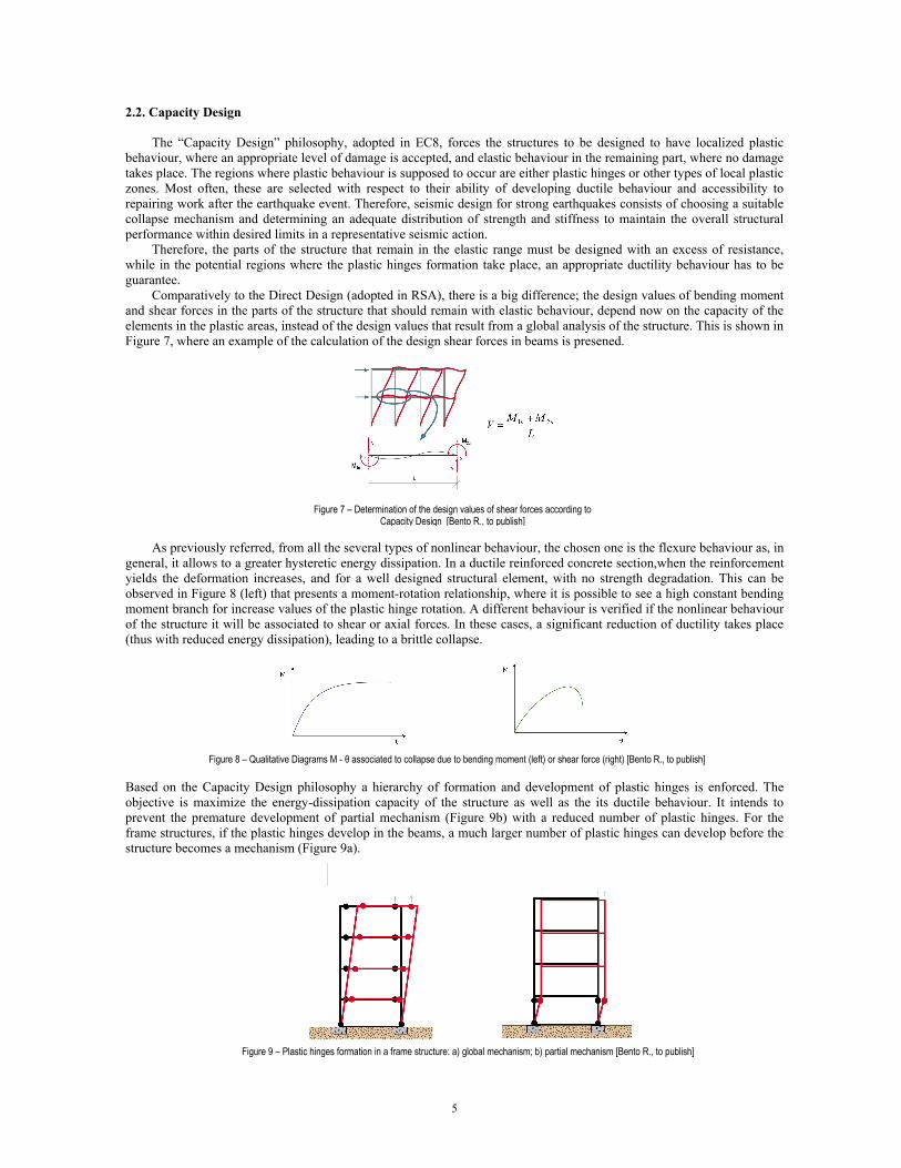
Comparatively to the Direct Design (adopted in RSA), there is a big difference; the design values of bending moment and shear forces in the parts of the structure that should remain with elastic behaviour, depend now on the capacity of the elements in the plastic areas, instead of the design values that result from a global analysis of the structure. This is shown in Figure 7, where an example of the calculation of the design shear forces in beams is presened.
Figure 7 – Determination of the design values of shear forces according to
Capacity Design [Bento R., to publish] As previously referred, from all the several types of nonlinear behaviour, the chosen one is the flexure behaviour as, in
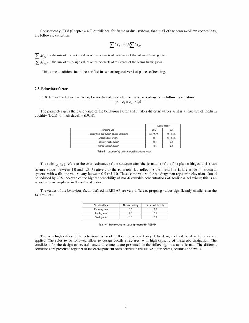
general, it allows to a greater hysteretic energy dissipation. In a ductile reinforced concrete section,when the reinforcement yields the deformation increases, and for a well designed structural element, with no strength degradation. This can be observed in Figure 8 (left) that presents a moment-rotation relationship, where it is possible to see a high constant bending moment branch for increase values of the plastic hinge rotation. A different behaviour is verified if the nonlinear behaviour of the structure it will be associated to shear or axial forces. In these cases, a significant reduction of ductility takes place (thus with reduced energy dissipation), leading to a brittle collapse.
Figure 8 – Qualitative Diagrams M - θ associated to collapse due to bending moment (left) or shear force (right) [Bento R., to publish]
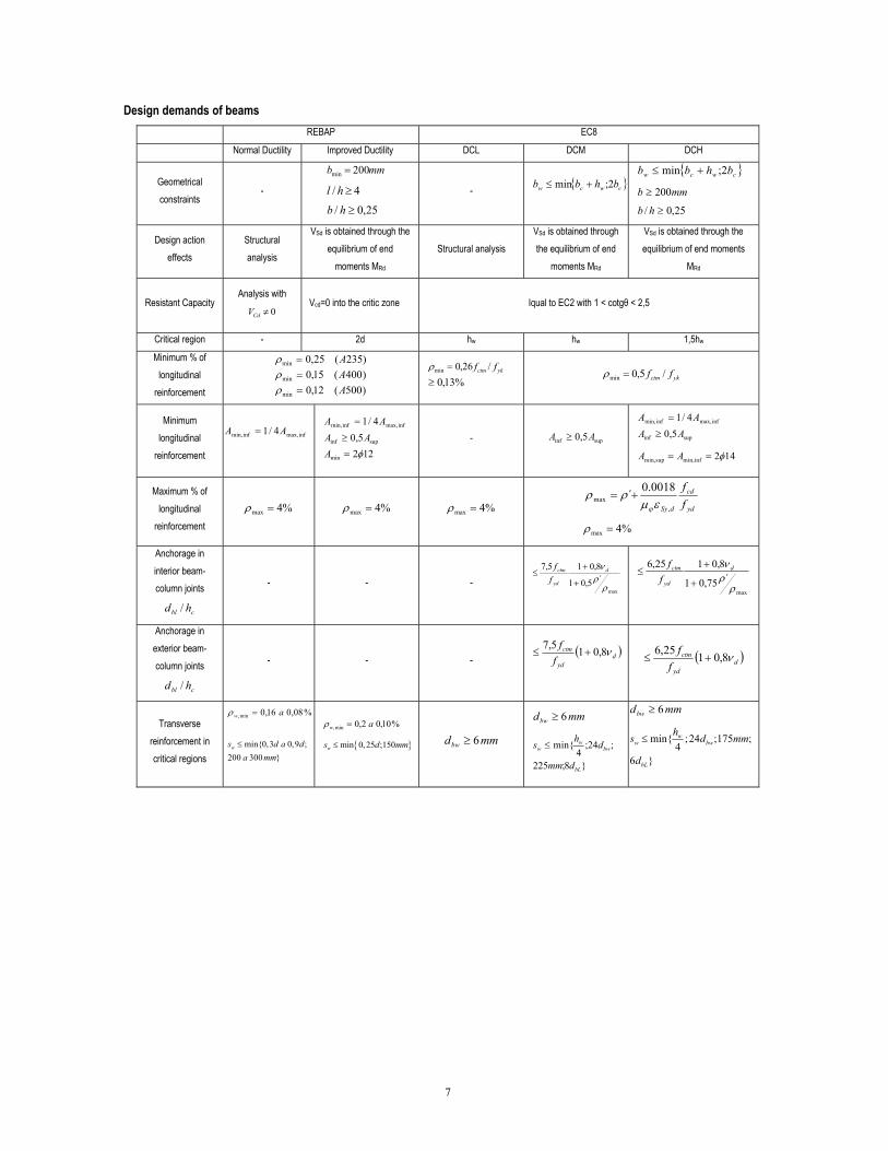
Based on the Capacity Design philosophy a hierarchy of formation and development of plastic hinges is enforced. The objective is maximize the energy-dissipation capacity of the structure as well as the its ductile behaviour. It intends to prevent the premature development of partial mechanism (Figure 9b) with a reduced number of plastic hinges. For the frame structures, if the plastic hinges develop in the beams, a much larger number of plastic hinges can develop before the structure becomes a mechanism (Figure 9a).
Figure 9 – Plastic hinges formation in a frame structure: a) global mechanism; b) partial mechanism [Bento R., to publish]
5
Consequently, EC8 (Chapter 4.4.2) establishes, for frame or dual systems, that in all of the beams/column connections, the following condition:
∑ ∑≥ RbRc MM 3,1
∑ RcM - is the sum of the design values of the moments of resistance of the columns framing join
∑ RbM - is the sum of the design values of the moments of resistance of the beams framing join
This same condition should be verified in two orthogonal vertical planes of bending.
2.3. Behaviour factor
EC8 defines the behaviour factor, for reinforced concrete structures, according to the following equation:
5,10 ≥×= wkqq The parameter q0 is the basic value of the behaviour factor and it takes different values as it is a structure of medium
ductility (DCM) or high ductility (DCH):
Structural type DCM DCH
Frame system, dual system, coupled wal system 3,0 αu /α1 4,5 αu /α1 Uncoupled wall system 3,0 4,0 αu /α1
Torsionally flexible system 2,0 3,0
Inverted pendulum system 1,5 2,0
Ductility classes
Table 5 – values of q0 to the several structural types
The ratio refers to the over-resistance of the structure after the formation of the first plastic hinges, and it can
assume values between 1.0 and 1.3. Relatively to the parameter kw, reflecting the prevailing failure mode in structural systems with walls, the values vary between 0.5 and 1.0. These same values, for buildings non-regular in elevation, should be reduced by 20%, because of the highest probability of non-favourable concentrations of nonlinear behaviour; this is an aspect not contemplated in the national codes.
1/ααu
The values of the behaviour factor defined in REBAP are very different, propsing values significantly smaller than the
EC8 values:
Structural type Normal ductility Improved ductilityFrame system 2,5 3,5Dual system 2,0 2,5Wall system 1,5 2,0
Table 6 – Behaviour factor values presented in REBAP
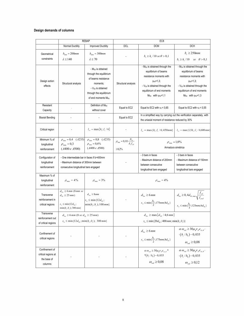
The very high values of the behaviour factor of EC8 can be adopted only if the design rules defined in this code are applied. The rules to be followed allow to design ductile structures, with high capacity of hysteretic dissipation. The conditions for the design of several structural elements are presented in the following, in a table format. The different conditions are presented together to the correspondent ones defined in the REBAP, for beams, columns and walls.
6
Design demands of beams REBAP EC8
Normal Ductility Improved Ductility DCL DCM DCH
Geometrical constraints
-
mmb 200min =
4/ ≥hl 25,0/ ≥hb
- { }cwcw bhbb 2;min +≤
{ }cwcw bhbb 2;min +≤
mmb 200≥
25,0/ ≥hb
Design action effects
Structural analysis
VSd is obtained through the equilibrium of end
moments MRd Structural analysis
VSd is obtained through the equilibrium of end
moments MRd
VSd is obtained through the equilibrium of end moments
MRd
Resistant Capacity Analysis with
0≠CdVVcd=0 into the critic zone
Iqual to EC2 with 1 < cotgθ < 2,5
Critical region - 2d hw hw 1,5hw
Minimum % of longitudinal
reinforcement
)235(25,0 A=minρ)400(15,0min A=ρ)500(12,0min A=ρ
ykctm ff /26,0min =ρ%13,0≥ ykctm ff /5,0min =ρ
Minimum longitudinal
reinforcement
infmax,infmin, 4/1 AA =
min
infmax,infmin, 4/1 AA =
supinf 5,0 AA ≥
122φ=A - supinf 5,0 AA ≥
infmax,infmin, 4/1 AA =
supinf 5,0 AA ≥
min,sup min,inf 2 14A A φ= =
Maximum % of longitudinal
reinforcement
%4max =ρ %4max =ρ
%4max =ρ
yd
cd
dSy ff
,max
0018.0´εμ
ρρϕ
+=
%4max =ρ
Anchorage in interior beam-column joints
cbl hd /
- - - maxρ
´5,01
8,015,7ρν
+
+≤ d
yd
ctm
ff
max
´75,01
8,0125,6
ρρν
+
+≤ d
yd
ctm
ff
Anchorage in exterior beam-column joints
cbl hd /
- - - ( )d
ctm
ff ν8,015,7
+≤yd
( )dctmf ν8,0125,6
+≤ydf
Transverse reinforcement in critical regions
mmdbw 6≥
min{ ;24 ;175 ;4
6 }
ww bw
bL
hs d m
d
≤
%08,016,0min, aw =ρ
min{0,3 0,9 ;200 300 }
ws d a da mm
≤
%10,02,0min, aw =ρ
{ }min 0, 25 ;150ws d mm≤ mmdbw 6≥
mmdbw 6≥
}8;225
;24;4
min{
bL
bww
w
dmm
dhs ≤ m
7
Design demands of columns
REBAP EC8
Normal Ductility Improved Ductility DCL DCM DCH
Geometrical constraints
mmb 200min =
140λ ≤
mmb 300min =
70λ ≤ - /10 0,1v vb h seθ≥ >
mmbc 250≥
/10 0,1v vb h se θ≥ >
Design action effects
Structural analysis
- MSd is obtained through the equilibrium
of beams resistance moments;
- VSd is obtained through the equilibrium of end moments MRd
Structural analysis
- MSd is obtained through the equilibrium of beams
resistance moments with γRd=1,3;
- VSd is obtained through the equilibrium of end moments
MRd with γRd=1,1
- MSd is obtained through the equilibrium of beams
resistance moments with γRd=1,3;
- VSd is obtained through the equilibrium of end moments
MRd with γRd=1,3
Resistant Capacity
- Definition of MRd
without cover Equal to EC2 Equal to EC2 with νd < 0,65 Equal to EC2 with νd < 0,55
Biaxial Bending - - Equal to EC2 In a simplified way by carrying out the verification separately, with the uniaxial moment of resistance reduced by 30%
Critical region - { }6/;max cccr lhl = -
max{ ; / 6; 450 }cr c cl h l mm=
}600;6/;5,1max{ mmlhl cccr =
Minimum % of longitudinal
reinforcement
)235(4,0 A=minρ
)500400(3,0min
AeA=ρ
)235(8,0min A=ρ
)500400(%6,0min
AeA=ρ min 0,01 d
c yd
NA f
ρ =
%2,0≥
%0,1min =ρ
Armadura simétrica
Configuration of longitudinal
reinforcement
- One intermediate bar in faces if b>400mm - Maximum distance of 300mm between consecutive longitudinal bars engaged
-
- 3 bars in faces - Maximum distance of 200mm between consecutive longitudinal bars engaged
- 3 bars in faces - Maximum distance of 150mm between consecutive longitudinal bars engaged
Maximum % of longitudinal
reinforcement
%4max =ρ
%3max =ρ
%4max =ρ
Transverse reinforcement in critical regions
)258(6
mmdsemmmmd
bL
bw
≥≥
min{12 ;min( ; );100 }
w bL
c c
s dh b mm
≤ min{12 ;
min( ; ); 300 }w bL
c c
s dh b mm
≤
mmdbw 8≥
- mmdbw 6≥
}8;175;min{ 0bLw dmmbs ≤
2
,max0,4 ydbw bL
ywd
fd d
f≥
}6;125;3
min{ 0bLw dmmbs ≤
Transverse reinforcement out of critical regions
)d m { }d 6 (8 25m se d mm≥ ≥
min{12 ; min( ; ); 300 }w bL c c
bw bL
s d h b mm≤
mmd bLbw 6;4/max≥
c min{20 ; 400 ; min( ; )}w bL cs d mm h b≤
Confinement of critical regions
- - -
mmdbw 6≥
}8;175;2
min{ 0bLw dmmbs ≤
( )
,
0
30
/ 0,035wd d sy d
cb bφα ω μ ν ε≥ ⋅
⋅ −
08,0≥wdω
Confinement of critical regions at
the base of columns
- - - ( ),
0
30 *
* / 0,035wd d sy d
cb bφα ω μ ν ε≥
−
08,0≥wdω
( ),
0
30
/ 0,035wd d sy d
cb bφα ω μ ν ε≥ ⋅
⋅ −
12,0≥wdω
8
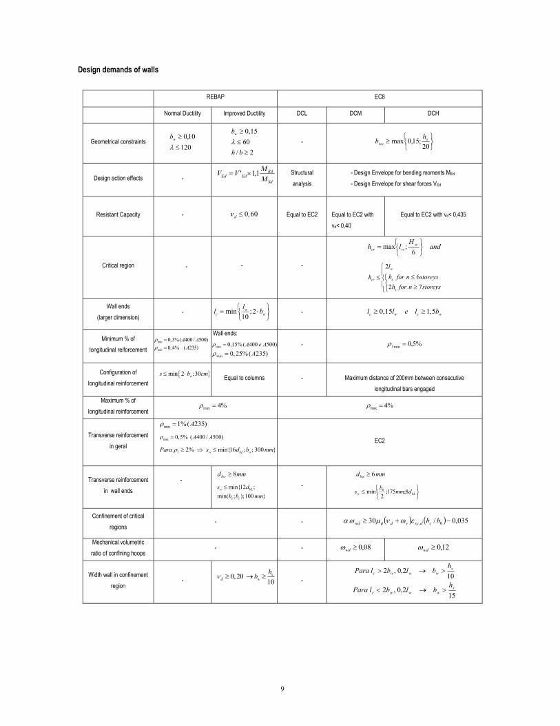
Design demands of walls
REBAP EC8
Normal Ductility Improved Ductility DCL DCM DCH
Geometrical constraints
120≤10,0≥
λwb
0,1560
/ 2
wb
h bλ
≥≤≥
-
⎭⎬⎫
⎩⎨⎧≥
20;15,0max s
wohb
Design action effects - Sd
RdEdEd M
MVV 1,1' ×=
Structural analysis
- Design Envelope for bending moments MEd - Design Envelope for shear forces VEd
Resistant Capacity - 0,60dν ≤ Equal to EC2
Equal to EC2 with νd< 0,40
Equal to EC2 with νd< 0,435
Critical region - - -
andH
lh wwcr
⎭⎬⎫
⎩⎨⎧=
6;max
⎪⎩
⎪⎨
⎧
⎩⎨⎧
≥≤≤
storeysnforhstoreysnforh
l
h
s
s
w
cr
726
2
Wall ends (larger dimension)
- min ;210
wc w
ll b⎧ ⎫= ⋅⎨ ⎬⎩ ⎭
c w c wb - 0,15 1,5l l e l≥ ≥
Minimum % of longitudinal reiforcement
min 0,3%( 400/ 500)
A Aρ =
min 0,4% ( 235)Aρ =
Wall ends:
min 0,15%( 400 500)A e Aρ =
min 0, 25% ( 235)Aρ = - %5,0minl =ρ
Configuration of longitudinal reinforcement
{ }s min 2 ;30wb cm≤ ⋅
Equal to columns -
Maximum distance of 200mm between consecutive
longitudinal bars engaged
Maximum % of longitudinal reinforcement max 4%ρ =
max 4%ρ =
Transverse reinforcement in geral
min 1%( 235)Aρ =
min 0,5% ( 400 / 500)A Aρ =
2% min{16 ; ; 300 }l w bL wPara s d b mmρ ≥ ⇒ ≤
EC2
Transverse reinforcement in wall ends
-
mmdbw 8≥
min{12 ;min( ; );100 }
w bL
c c
s dh b mm
≤ -
mmdbw 6≥
⎭⎬⎫
⎩⎨⎧≤ bLw dmm
bs 8;175;
2min 0
Confinement of critical regions
- - ( ) ( ) 035,0/30 −+≥ bbεωνμωα 0, cdsyvdwd φ
Mechanical volumetric ratio of confining hoops
- - 08,0≥wdω 12,0≥wdω
Width wall in confinement region
- 0,2010
sd w
hb 102,0,2 s
wwwch
blblPara >→>ν ≥ → ≥
-
152,0,2 s
wwwch
blblPara >→<
9
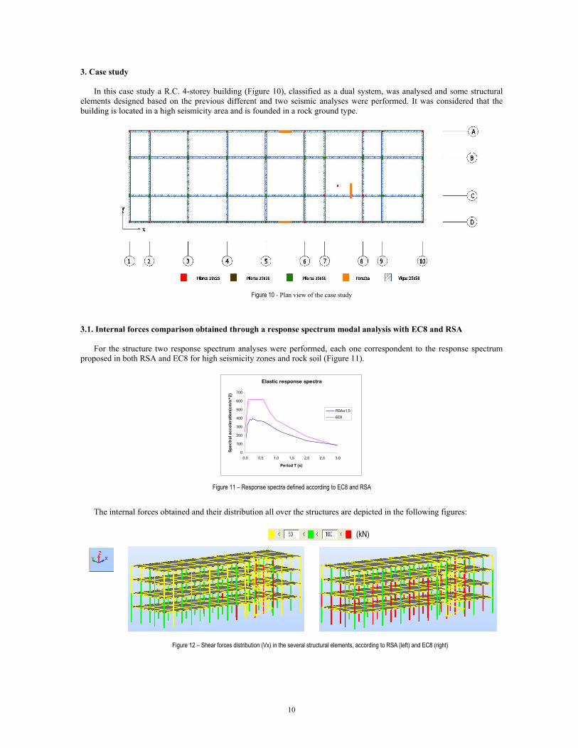
3. Case study
In this case study a R.C. 4-storey building (Figure 10), classified as a dual system, was analysed and some structural elements designed based on the previous different and two seismic analyses were performed. It was considered that the building is located in a high seismicity area and is founded in a rock ground type.
Figure 10 - Plan view of the case study
3.1. Internal forces comparison obtained through a response spectrum modal analysis with EC8 and RSA
For the structure two response spectrum analyses were performed, each one correspondent to the response spectrum
proposed in both RSA and EC8 for high seismicity zones and rock soil (Figure 11).
Elastic response spectra
0
100
200
300
400
500
600
700
0,0 0,5 1,0 1,5 2,0 2,5 3,0
Period T (s)
Spec
tral
acc
eler
atio
n(cm
/s^2
)
RSAx1,5
EC8
Figure 11 – Response spectra defined according to EC8 and RSA The internal forces obtained and their distribution all over the structures are depicted in the following figures: (kN)
Figure 12 – Shear forces distribution (Vx) in the several structural elements, according to RSA (left) and EC8 (right)
10

(kN)
Figure 13 – Shear forces distribution (Vy) for the several structural elements, according to RSA (left) and EC8 (right)
The elastic internal forces obtained through the EC8 response spectrum are higher than the obtained with the RSA, with values 50% and 60% higher. As expected, the elastic EC8 response spectrum analysis and for a long distant earthquake, a high seismicity zone and rock ground type, leads to higher values of internal forces than the ones obtained by means of RSA response spectrum analysis. However, these internal forces could be reduced, substantially, if an high value of the behaviour factor is adopted (only possible for ductile structures with capacity of energy dissipation).
3.2. Design of a column, wall and beams according to EC8 and RSA/REBAP
In this section the design of a column (Figure 15 and Tables 8 and 9), the adjacent beams (Figure 14 and Table 7) and a wall (Figure 16 and Tables 10 and 11) and according to EC8 and RSA/REBAP are presented. Being the structure a dual system, was defined distinct behaviour factor, whose values was 3,9 and 2,0 according to EC8 and RSA, respectively.
REBAP EC8 Differences (%) ρ (%) Reinforcement ρ (%) Reinforcement Differences (%)
53,3 53,3 0% 0,36 2 Ø 16 0,36 2 Ø 16 0%113,1 102,4 10% 0,54 3 Ø 16 0,54 3 Ø 16 0%
REBAP EC8 Differences (%) ρ (%) Reinforcement ρ (%) Reinforcement Differences (%)
52,2 52,2 0% 0,36 2 Ø 16 0,36 2 Ø 16 0%203,6 173,8 17% 1,12 4 Ø 20 0,89 5 Ø 16 25%
M máx+
M máx-
REBAP
REBAP
Beam X
M máx+
M máx-
Beam Y
Msd (kNm)
Msd (kNm)
EC8
EC8
REBAP EC8 Differences (%) REBAP EC8 Differences (%)100,8 94,8 6% 0,11% 0,18% 60%
Ø 6 // 20cm Ø 6 // 12,5cm
REBAP EC8 Differences (%) REBAP EC8 Differences (%)184,1 132,3 39% 0,46% 0,18% 155%
Ø 8 // 17,5cm Ø 6 // 12,5cm
Beam Y
ρw
ρw
V Sd (kN)
Beam X
V Sd (kN)
Table 8 – Shear forces and respective reinforcement, obtained according to EC8 and RSA/REBAP
Figure 14 – Design of the beam X according to RSA/REBAP (left) and EC8 (right)
0,25
0,5
0,5
0,25 0,250,5
0,5
0,25
Table 7 –Bending moments and respective reinforcement, obtained according to EC8 and RSA/REBAP
11
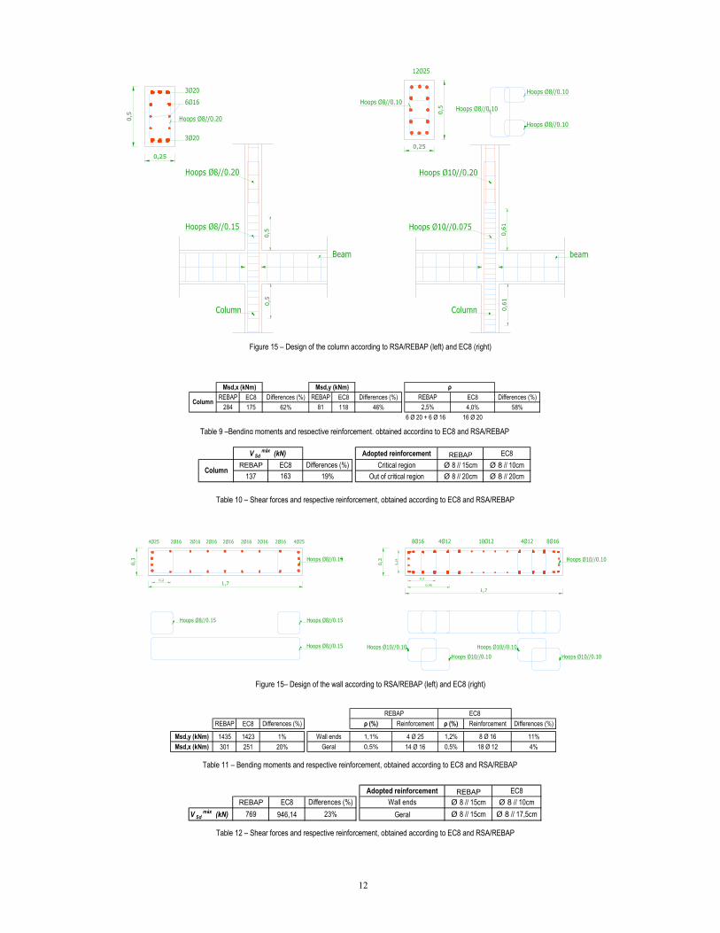
REBAP EC8 Differences (%) REBAP EC8 Differences (%) REBAP EC8 Differences (%)284 175 62% 81 118 46% 2,5% 4,0% 58%
6 Ø 20 + 6 Ø 16 16 Ø 20
Column
Msd,x (kNm) Msd,y (kNm) ρ
Adopted reinforcement REBAP EC8REBAP EC8 Differences (%) Critical region Ø 8 // 15cm Ø 8 // 10cm
137 163 19% Out of critical region Ø 8 // 20cm Ø 8 // 20cm
V Sdmáx
(kN)
Column
REBAP EC8 Differences (%) ρ (%) Reinforcement ρ (%) Reinforcement Differences (%)
Msd,y (kNm) 1435 1423 1% Wall ends 1,1% 4 Ø 25 1,2% 8 Ø 16 11%Msd,x (kNm) 301 251 20% Geral 0,5% 14 Ø 16 0,5% 18 Ø 12 4%
REBAP EC8
Adopted reinforcement REBAP EC8REBAP EC8 Differences (%) Wall ends Ø 8 // 15cm Ø 8 // 10cm
V Sdmáx
(kN) 769 946,14 23% Geral Ø 8 // 15cm Ø 8 // 17,5cm
Figure 15 – Design of the column acco ding to RSA/REBAP (left) and EC8 (right) r
Figure 15– Design of the wall accord RSA/REBAP (left) and EC8 (right) ing to
Table 12 – Shear forces and respective reinforcement, obtained according to EC8 and RSA/REBAP
Table 10 – Shear forces and respective reinforcement, obtained according to EC8 and RSA/REBAP
Table 9 –Bending moments and respective reinforcement, obtained according to EC8 and RSA/REBAP
Table 11 – Bending moments and respective reinforcement, obtained according to EC8 and RSA/REBAP
0,5
0,5
0,5
0,25
0,61
0,61
0,25
0,5
0,3
1,70,2
1,7
0,3
0,3
0,24
0,45
12
4. Conclusions
After the comparison of EC8 with RSA / REBAP, it is evident that there are significant differences between the different codes.
EC8, oppose to RSA, defines the seismic action function of two different seismic zones for national territory, depending on the type of the seismic action considered.
Relatively to the seismic action definition, EC8 presents response spectra quite different of the ones defined in RSA. For rock ground type soil and according to EC8, the north areas of Portugal are subjected to less severe acceleration response spectrum, while in the south, an area of high seismicity, for the distant seismic action one high acceleration response spectrum is proposed.
It is important to highlight that, for soft soils, the discrepancy between the response spectra proposed in the two codes, is more evident; the acceleration response spectrum values, according to EC8, and for the two types of seismic action for almost all the national territory, are significantly higher than the RSA spectrum values. In fact, the RSA code defined smaller values of response spectrum for soft soils, in comparison with the values it proposes for stiff soils.
For the design of structures the EC8 adopts the “Capacity Design” philosophy. It enforces the structures to be designed to have localized plastic behaviour, where an appropriate level of damage is accepted, and elastic behaviour in the remaining part, where no damage takes place. Based on this philosophy the seismic design for strong earthquakes proposes to choose a suitable collapse mechanism and determining an adequate distribution of strength and stiffness to maintain the overall structural performance within desired limits for a representative seismic action. On the other hand, REBAP follows the Direct Design method, in which where the nonlinear behaviour takes place is not a priority, and the seismic action resistance of structure depends essentially on the capacity of the several structural elements. Nevertheless, REBAP presents some similar demands to the Capacity Design concept, but only for the improved ductility structures, however, in most of the cases, this type of design is not adopted (only for some special structures is considered).
Based on the Capacity Design philosophy a hierarchy of formation and development of plastic hinges is enforced. The objective is maximizing the energy-dissipation capacity of the structure as well as its ductile behaviour. The method of design intends to prevent the premature development of partial mechanism, with a reduced number of plastic hinges. For the frame structures, if the plastic hinges develop in the beams, a much larger number of plastic hinges can develop before the structure becomes a mechanism, leading to higher hysteretic energy dissipation and a better control of damage.
The EC8 code adopts three ductility classes, namely, DCL, DCM and DCH, corresponding to lower, medium and high ductility, where DCL class is similar to the normal ductility class of REBAP.
For the DCM and DCH structures, EC8 defines high values of behaviour factors, where some demanding conditions are proposed in terms of design conditions. Significant differences do exist between the conditions to follow according REBAP rules, for the definition of the longitudinal and transverse reinforcement of the structural elements, and the ones presented in EC8.
Firstly, EC8 presents a higher demanding conditions for the definition of the percentages of longitudinal reinforcement, enforces to a smaller spacing between longitudinal reinforcement of columns and walls - while REBAP allows 30cm, EC8 (based on EC2 rules) enforces to a maximum spacing of 15cm. Moreover, EC8 also requires a smaller spacing of the hoops in columns and walls, giving a great importance to the confinement reinforcement to adopt in the vertical elements. EC8 demands a minimum area of confinement reinforcement to adopt in critical areas of columns and walls, which zones correspond to the joint beams-columns and to the base of wall.
However, is in the definition of the confinement reinforcement that EC8 presents a great lack of clearness, namely in the description of several parameters, where their definition becomes quite complicated mainly due to the little information presented in EC8. It is recommended the existence of a background document, in which it could be defined in a clearer and detailed way the equations proposed in EC8 for the definition of several parameters. In this document some examples of application could also be included.
Another issue, also related with the incomprehensible definitions stated in EC8, is the definition of the flexural resistance of columns, based on the concept of “weak beam – strong column”. In the definition of this criterion is not presented which percentage of the parameter is distributed above and below the joint connection.
Besides, as the moment resistance of mns is calculated from the real resistance of the beams section that are adjacent, and then is affected by the 1.3 coefficient, the values of longitudinal reinforcement percentage can be greater than 4%, the maximum value defined in the code. Then, it forces to the definition of higher values for the column dimensions. Consequently, one can say that the Capacity Design philosophy can enforce to different column sections, leading in some cases to some incompatibilities at architectonic level.
the colu∑ RcM
Relatively to the results obtained in the case study, a mixed structure founded in rock ground type, in an area of high seismicity, the EC8, comparatively to RSA / REBAP codes, originates more demanding reinforcement solutions, namely for the vertical elements. This happens, not only because of the seismic action definition (the high values of the acceleration response spectrum proposed by the EC8 are significantly reduced by means of the behaviour coefficient values proposed), but mainly due to design rules adopted for the several structural elements.
13
References Appleton, J; Marchão, C. – “Folhas da cadeira de Betão Armado e Pré-esforçado I”, disciplina de Betão Armado e Pré-esforçado I, Instituto Superior Técnico, 2005/2006 Bento, R.; Lopes M. – “Modelação Fisicamente Não Linear de Estruturas de Betão Armado”, disciplina de Modelação e Análise Estrutural, Instituto Superior Técnico, 1999-2000 Bento, R.; Lopes M. – “Seismic Behaviour of Dual Systems with Column Hinging”, Earthquake Spectra, Vol. 17, Nº 4, Nov 2001 Capítulo 5,6 e 11 do Livro "Sismos e edifícios", edições Orion, a publicar Correia, R.M. – LNEC, “Apresentação para o Anexo Nacional do Eurocódigo 8 – Acção sísmica e influência das condições geotécnicas”, 2006. Dias, H, “Comparação do RSA com o Eurocódigo 8 – Dimensionamento de pilares, vigas e paredes em estruturas de betão armado”, Dissertação de Mestrado, Instituto Superior Técnico, 2007 EN 1992-1-1: Dec 2004; “Eurocode 2: Design of concrete structures – Par 1-1 General rules and rules for buildings”, CEN, Brussels, Belgium, 2004 EN 1998-1 Dec 2004; “Eurocode 8: Design of structures for earthquake resistance – Part 1: General rules, seismic action and rules for buildings”, CEN, Brussels, Belgium, 2004 ENV 1998-1-3 2002; “Eurocódigo 8: Disposições para projecto de estruturas sismo-resistentes – Parte 1-3: Regras gerais – Regras específicas para vários materiais e elementos”, LNEC, 2002 Fardis, M.; Carvalho, E.; Elnashai, A.; Faccioli, E.; Pinto, P.; Plumier, A. – “Designers’s guide to EN 1998-1 and EN1998-5 Eurocode 8: Design of structures for Earthquake resistance. General rules, seismic actions, design rules for buildings, foundations and retaining structures”, Thomas Telford, London, 2005 Gomes, A.; Vinagre, J. - “Betão Armado e Pré-Esforçado I – Tabelas de Cálculo”, disciplina de Betão Armado e Pré-Esforçado I, Instituto Superior Técnico, 1997 LNEC, Apresentação da “Proposta de definição da acção sísmica para o projecto de estruturas – Anexo Nacional do EC8”, Grupo de Trabalho do Eurocódigo 8, 2006 REBAP; “Regulamento de Estruturas de Betão Armado e Pré-Esforçado”; Decreto-Lei nº349-c/83, de 30 Julho e Decreto-Lei nº 128-99, de 21 Abril, Porto Editora, 2004 RSA; “Regulamento de Segurança e Acções para estruturas de Edifícios e Pontes”; Decreto-Lei nº 235/83, de 31 Maio, Porto Editora, 2005 Sousa, J. – “Amplificação de Vibrações Sísmicas Nalguns Solos de Lisboa”, Dissertação de Mestrado, Instituto Superior Técnico, 2004
14