comparision of edge detection methods for obstacles …€¦ · edge detection methods for...
TRANSCRIPT
27TH DAAAM INTERNATIONAL SYMPOSIUM ON INTELLIGENT MANUFACTURING AND AUTOMATION
DOI: 10.2507/27th.daaam.proceedings.035
COMPARISION OF EDGE DETECTION METHODS FOR OBSTACLES
DETECTION IN A MOBILE ROBOT ENVIRONMENT
Boris Crnokić, Snježana Rezić, Slaven Pehar
University of Mostar, Faculty of Mechanical Engineering and Computing, Matice hrvatske bb, 88000, Mostar, BiH
This Publication has to be referred as: Crnokic, B[oris]; Rezic, S[njezana] & Pehar, S[laven] (2016). Comparision of
Edge Detection Methods for Obstacles Detection in a Mobile Robot Environment, Proceedings of the 27th DAAAM
International Symposium, pp.0235-0244, B. Katalinic (Ed.), Published by DAAAM International, ISBN 978-3-902734-
08-2, ISSN 1726-9679, Vienna, Austria
DOI: 10.2507/27th.daaam.proceedings.035
Abstract
This paper presents application of different edge detection methods for detecting of obstacles in the environment of
mobile robot. Autonomous mobile robots operating in an unknown environment must be able to cope with hazards and
obstacles, and at the same time to navigate through the environment performing required tasks. Detection and avoidance
of obstacles, collisions and hazardous situations is a very important part of reliable and secure navigation of mobile
robots. Vision sensor (camera) provides large amount of data about obstacles in the environment, however it is
necessary to extract only the most important details. This paper will present a comparison of the four most common
edge detection methods on examples of obstacles detection in different conditions. Methods used in this study are:
Sobel, Prewitt, Roberts and Canny.
Keywords: Mobile Robot; Robot Vision; Obstacle Recognition; Edge Detection.
1. Introduction
In the last two decades mobile robots are attracting more attention of scientists because their range of use is
increasing in various fields such as space research, underwater exploration, automotive, military, medical, service
robots, robots for serving and entertainment, etc. Mobile robots have to possess some autonomy, intelligence and ability
to navigate in an unknown surrounding, which is a fundamental problem for mobile robots. Robot navigation requires
guidance of mobile robot through desired path to the desired goal avoiding obstacles and hazards encountered in an
unknown environment.[1] Detection and avoidance of obstacles, collisions and hazardous situations is in the first place,
however, path planning and arrival at the desired goal is also a very important part of reliable and secure navigation of
mobile robots. Planning the optimal path requires optimization of specific performance of navigation, such as minimum
- 0235 -

27TH DAAAM INTERNATIONAL SYMPOSIUM ON INTELLIGENT MANUFACTURING AND AUTOMATION
time until robot reaches desired goal with a minimum of control, but also requires to comply with certain restrictions in
robot motion, such as avoiding obstacles with the maximum speed of the robot.
Generally, all obstacles or hazards in the urban surrounding of the robot, can be classified as [2]:
Drop offs (sidewalk curbs, downward stairs, steps);
Static obstacles (walls, furniture);
Dynamic obstacles (people, doors);
Invisible obstacles (glass doors and glass walls);
Overhangs (table tops, railings, tree branches);
Inclines (wheelchair ramps, curb cuts);
Rough surfaces (travel paths, grass beds).
Narrow regions (doorways, elevators).
To avoid collision with obstacles in the environment, robots should be equipped with sensor system that will enable
detection of these obstacles. Informations obtained from sensors are used in obstacle avoidance strategies, or in
strategies for finding best solution in case of emergency stop of robot before collision.[1] Obstacle detection can be
classified into two types [3]:
Ranged-based obstacle detection.
Appearance-based obstacle detection.
Obstacle criterion is important difference between these two obstacle detection systems. In range-based systems,
obstacles are objects that protrude a minimum distance from the ground. In appearance-based systems, obstacles are
objects that differ in appearance from the ground.[4] In case of range-based obstacle detection, sensors scan the area
and detect any obstacle within the range, also sensors calculate the range between the robot and the obstacle. In
appearance based obstacle detection, the physical appearance of the obstacle is detected from the environment, usually
by image processing.[3] Vision sensors provide large quantity of data from the environment that are useful for obstacles
detection. However, this large quantity of data also represents great computational complexity for processing circuitry
of the mobile robot, so it is necessary to extract only the most important details. One way to extract only the most
important details are methods for detecting the edges of obstacles placed in the robot's surrounding. In this paper we
will present comparison of the four most commonly used methods for edge detection: Sobel, Prewitt, Roberts and
Canny.
These edge detection methods were used in various systems for edge detection in different environments and
scenarios. Each method has strengths and weaknesses and its particularities. Sobel, Prewitt and Roberts methods uses
derivatives on an intensity map to calculate the maximum change in the gradient at an edge [5]. Canny algorithm has
the ability to achieve a low error-rate by eliminating almost all non-edges and improving the localization of all
identified edges [6]. Various authors have compared these methods on a variety of examples in the application of
detected edges to perform different tasks. On the example of edge detection for mobile robot on lunar surface and
surroundings [5] it is noticed that Canny edge algorithm results in highly detailed edges but it is not desirable in a
defined textured scene, good result provided Sobel operator for detecting high concentration edges. Comparison of
these methods was done through a navigation system of a mobile robot using Pan Tilt Zoom network camera mounted
on the robot as the primary sensor for robot navigation [7]. Application and comparison of these methods is presented
trough edge detection algorithm for vision guided robotics which showed that Canny’s edge detection algorithm gives
better result and minimum error [8]. The edge detection techniques Canny, Prewitt, Roberts and Sobel are compared in
paper to detect the obstacles with the precision of free Google Maps API [9]. In the papers [10]–[12] through various
experiments, comparisons of these four methods have shown that Canny algorithm is computationally more expensive
compared to Sobel, Prewitt and Robert methods. However, the Canny algorithm performs better in different
environments and scenarios, also under noisy conditions and indicates better performance.
This paper presents comparison of Sobel, Prewitt, Roberts and Canny methods to select best edge detection method
that will be used for mobile robot indoor navigation. Future work is based on the development of mobile robot
navigation system with a fusion of infrared sensors and camera, where most suitable of these edge detecting methods
will be used.
2. METHOD USED
2.1. Hardware and Software Used
Hardware used in this paper includes a mobile robot Robotino 2 (Fig. 1.) and a laptop, while the application
algorithms were implemented in MATLAB/Simulink programming environment. Robotino is a fully functional, high
- 0236 -

27TH DAAAM INTERNATIONAL SYMPOSIUM ON INTELLIGENT MANUFACTURING AND AUTOMATION
quality mobile robotic system with omnidirectional wheel drive. The system can work independently but also linked to
an external computer system (Wi-Fi connection). Robotino possesses different types of sensors. Some of these sensors
are built-in as standard equipment, such as: VGA camera, infrared sensors, incremental encoder and bumper. Other
sensors come as an upgrade, such as: analog inductive distance sensor, gyroscope or a navigation system. Robotino
controller unit consists of 3 components [13], [14]:
PC 104 processor, 300 MHz, and Linux operating system with real-time kernel, SDRAM 128 MB
Compact flash card with C++ API for controlling Robotino
Wireless LAN access point
Controller unit is equipped with the following interfaces: Ethernet, 2 ea. USB and VGA. Power is supplied by two
rechargeable 12 V batteries. Robotino is equipped with a camera system. Its height and inclination can be adjusted, and
connects to Robotino via USB port. The camera makes it possible to display live images using different programming
interfaces, including MATLAB/Simulink. Technical specifications of the camera are shown in Table 1.
Fig. 1. Mobile robot Robotino 2 and VGA camera [13]
Technical Specifications
Image Sensor Colour VGA CMOS
Colour Depth 24 Bit True Colour
PC-connection USB 2.0 (compatible with USB 1.1)
Video resolutions 320 x 240, (QVGA), 30 images/second
640 x 480, (VGA), 30 images/second
Robotino View can process this resolution
800 x 600(SVGA, software-interpolated), 30 images/second
Still image
resolutions
640 x 480 (VGA)
800 x 600(SVGA)
1024 x 768 (SXGA, software-interpolated)
Still capture
format BMP, JPG
Table 1. Technical specificatios of VGA camera [13]
2.2. Edge Detection Methods
Edge detection is one of the most important parts in the image processing systems of mobile robots navigation. It
allows the extraction and display of features such as curves, lines and angles for the purposes of identifying images
from the environment. Images represented by edges are widely used to simplify the process of identifying and
interpreting images to the navigation systems of mobile robots which use camera as primary sensor.[15]
Main idea in edge detection process is based on an abrupt change in the intensity of pixels between adjacent pixels
in the image. The edge represents a location that forms the border between the pixels of high and low intensity. Abrupt
transition in the intensity of pixels requires the application of derivative operators to create a gradient images. The edge
detector can be defined as a mathematical operator that corresponds to spatial variations and discontinuities in the
grayscale pixel set in the image. The edge is indicated with a rapid changes within the picture that shows the
- 0237 -

27TH DAAAM INTERNATIONAL SYMPOSIUM ON INTELLIGENT MANUFACTURING AND AUTOMATION
characteristic features and can therefore be characterized as a set of pixels whose intensity of environmental follows
continuous variation.
The quality of edge detection largely depends on light conditions, the presence of objects of similar intensity,
density of edges in the scene and noises. Different edge detectors work better under different conditions, and therefore
there is no uniform algorithm that can be adapted to all conditions in the environment. An "optimal" edge detector
means [16]:
Good detection – the algorithm should mark real edges in the image as possible.
Good localization – Marked edges should be as close as possible to the edge in the real image.
Minimal response – a given edge in the image should only be noticeable once, and where possible, image noise
should not generate false edges.
Ideal would be to use an algorithm that simultaneously uses different detectors applying each of them when
conditions in environment are ideal for that particular method. This paper will present comparison of four methods for
detecting edges of obstacles that mobile robot encounters. These methods are: Sobel, Prewitt, Roberts and Canny.
Sobel Edge Detector
Sobel operator uses two 3×3 kernels which are convolved with the original image to calculate approximations of the
derivatives, one for horizontal changes, and one for vertical changes. To produce separate measurements of the gradient
component in each orientation, kernels can be applied separately to the input image (Gx - in direction of the X-axis; Gy
– in direction of Y-axis), as follows: [18]
𝐺𝑥 = [−1 0 +1−2 0 +2−1 0 +1
] 𝑎𝑛𝑑 𝐺𝑦 = [−1 −2 −10 0 0
+1 +2 +1] (1)
The x-coordinate is defined as increasing in the "right"-direction, and the y-coordinate is defined as increasing in the
"down"- direction. These can then be combined together to find the resulting gradient approximations at each point in
the image, to give the gradient magnitude:
𝐺 = √𝐺𝑥2 + 𝐺𝑦
2 (2)
Then, it is possible to calculate the gradient's direction:
𝜃 = 𝑎𝑟𝑐𝑡𝑎𝑛 (𝐺𝑦
𝐺𝑥
) (3)
Prewitt edge detector
Prewitt operator is very similar to the Sobel operator, and also utilizes two masks which enable calculation of pixel
intensity gradient in the vertical and horizontal directions. The overall gradient and edge orientation is calculated in the
same way [17], [18]:
𝐺 = √𝐺𝑥2 + 𝐺𝑦
2 𝑎𝑛𝑑 𝜃 = 𝑎𝑟𝑐𝑡𝑎𝑛 (𝐺𝑦
𝐺𝑥
) (4)
Horizontal (Gx) and vertical (Gy) derivative approximations are computed as:
𝐺𝑥 = [−1 0 +1−1 0 +1−1 0 +1
] 𝑎𝑛𝑑 𝐺𝑦 = [−1 −1 −10 0 0
+1 +1 +1] (5)
Roberts edge detector
The Roberts detector performs a simple, quick to compute, 2-D spatial gradient measurement on an image. Pixel
values at each point in the output represent the estimated absolute magnitude of the spatial gradient of the input image
at that point. The operator consists of a pair of 2×2 convolution kernels. These kernels are designed to respond
maximally to edges running at 45° to the pixel grid, one kernel for each of the two perpendicular orientations. The
kernels can be applied separately to the input image, to produce separate measurements of the gradient component in
each orientation (Gx and Gy).This is very similar to the Sobel operator. In order to perform edge detection with the
- 0238 -
27TH DAAAM INTERNATIONAL SYMPOSIUM ON INTELLIGENT MANUFACTURING AND AUTOMATION
Roberts operator initially it is necessary to convolve the original image, with the following two kernels [11], [17]:
𝐺𝑥 = [+1 00 −1
] 𝑎𝑛𝑑 𝐺𝑥 = [0 +1
−1 0] (6)
These can then be combined together to find the absolute magnitude of the gradient at each point and the orientation
of that gradient:
𝐺 = √𝐺𝑥2 + 𝐺𝑦
2 (7)
The direction of the gradient can also be defined as follows:
𝜃 = 𝑎𝑟𝑐𝑡𝑎𝑛 (𝐺𝑦
𝐺𝑥
) −3𝜋
4 (8)
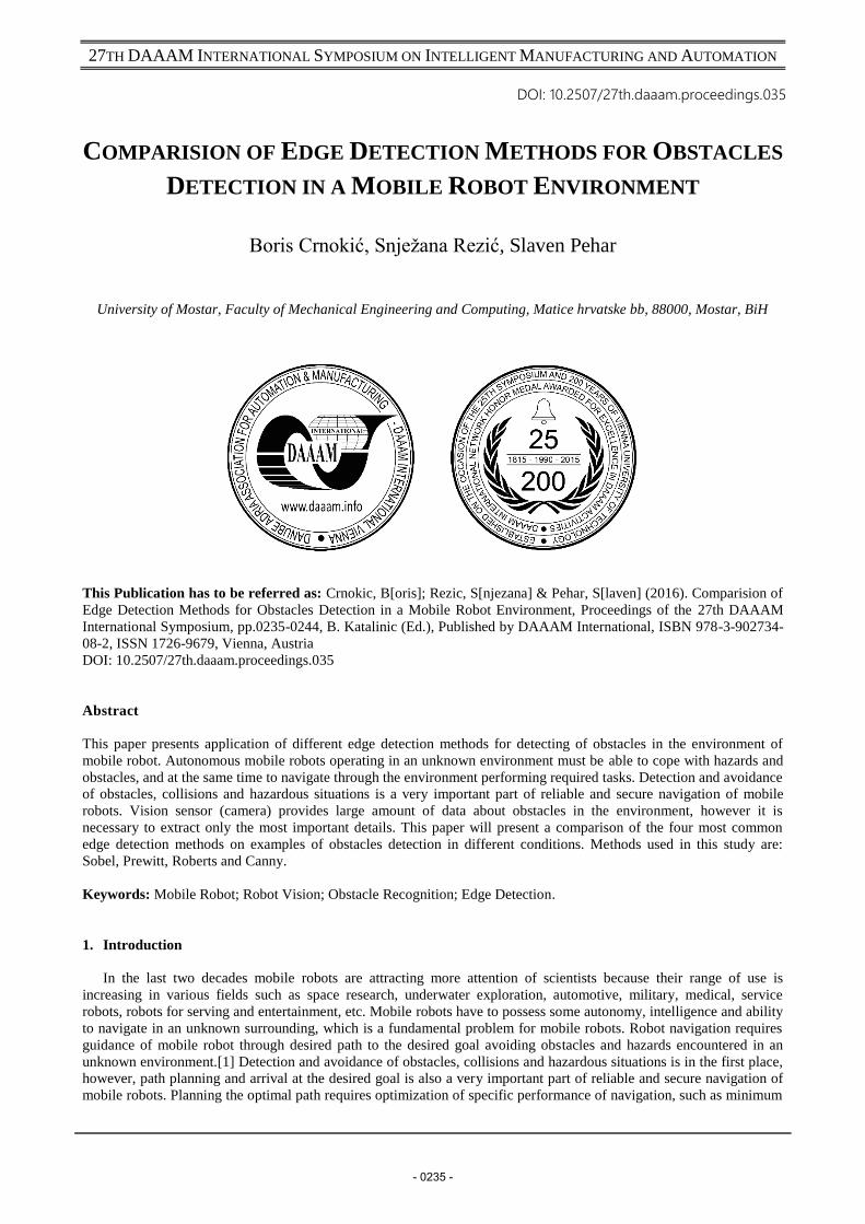
Canny Edge Detector
The Canny edge detector is known as the optimal edge detector. John F. Canny in 1986 introduced a multi-stage
algorithm for detecting a wide range of edges. He discussed a mathematical problem of derivation of optimal smoothing
filter with respect to the criteria of detection, localization and minimization of multiple responses of one edge.[19]
Canny saw the edge detection problem as a signal processing optimization problem, so he developed an objective
function to be optimized. The solution to this problem was a rather complex exponential function, but Canny found
several ways to approximate and optimize the edge-searching problem. Steps in the canny edge detector are as follows
[17], [19]:
1. Smoothing: Blurring of the image to remove noise.
2. Finding gradients: The edges should be marked where the gradients of the image has large magnitudes.
3. Non-maximum suppression: Only local maxima should be marked as edges.
4. Double thresholding: Potential edges are determined by thresholding.
5. Edge tracking by hysteresis: Final edges are determined by suppressing all edges that are not connected to a very
certain (strong) edge.
The block diagram of Canny edge detection algorithm is shown in Figure 2.
Fig. 2. Block diagram of Canny edge detector [19]
3. Implementation
Sobel, Prewitt, Roberts and Canny edge detection algorithms are implemented using MATLAB Simulink models by
using Video and Image Processing Blocksets from Simulink of MATLAB 7.10 (2010a). Manufacturer (Festo) of mobile
robot Robotino has provided an upgrade for MATLAB/Simulink. This also includes Simulink Blockset with blocks for
connecting to Robotino and to control all its components, including the camera, motors, sensors, etc.
Exactly the same blocks and the same structure is used for Sobel, Prewitt and Roberts edge detector Simulink
models (Fig. 3.).
- 0239 -

27TH DAAAM INTERNATIONAL SYMPOSIUM ON INTELLIGENT MANUFACTURING AND AUTOMATION
Fig. 3. Sobel edge detection Simulink model for Robotino
The only thing that was changed for each method is the selection of exactly preferred method in the "Function Block
Parameters" of “Edge Detection” block (Fig. 4.). For Sobel, Prewitt, and Roberts, the “Edge Detection” block finds the
edges in an input image by approximating the gradient magnitude of the image. The block convolves the input matrix
with the Sobel, Prewitt, or Roberts kernel, and outputs two gradient components of the image, which are the result of
this convolution operation. Alternatively, the block can perform a thresholding operation on the gradient magnitudes
and output a binary image, which is a matrix of Boolean values. If a pixel value is 1, it is an edge. [16], [17]
After starting the simulation, Robotino is moving and observing with a camera various obstacles in the environment.
Image from the camera passes through the “Edge Detection” block and appears as an image with edges in the “Video
Viewer” block. For comparison, on other monitor is possible to see real image of the obstacle.
Fig. 4. Selection of methods for edge detection
Canny edge detector Simulink model is created with the same blocks as in the previous case and with some new
blocks (Fig. 5.). [20] Fixed-point input is not supported for Canny edge method in Simulink. “Gaussian Noise
Generator” and “Median Filter” blocks are used. It is necessary to add noise to the image using a Gaussian noise
generator in the order to test the model in noisy environment. “Median Filter” is used to reduce the effect on noise
- 0240 -

27TH DAAAM INTERNATIONAL SYMPOSIUM ON INTELLIGENT MANUFACTURING AND AUTOMATION
present in the image.[21] For Canny method, the “Edge Detection” block finds edges by looking for the local maxima
of the gradient of the input image. It calculates the gradient using the derivative of the Gaussian filter. The Canny
method uses two thresholds to detect strong and weak edges. It includes the weak edges in the output only if they are
connected to strong edges. As a result, the method is more robust to noise, and more likely to detect true weak
edges.[17], [21], [22]
Fig. 5. Canny edge detection Simulink model for Robotino
4. Results
Results of edge detection of some characteristic obstacles are presented in this section. First of all, the Simulink
models of Sobel, Prewitt, Roberts and Canny edge detector were tested with different parameters, under different
lighting conditions, and thereafter edge detection was performed with the best configuration for each model. Sobel,
Prewitt and Roberts Simulink model were tested with different values of “Threshold scale factor” (TSF), which is used
to automatically calculate threshold value. Threshold scale factor was combined with the option “Edge thinning” (ET).
Values of the Threshold scale factor were from 1 to 4. Canny model was tested with different values of “Approximate
percentage of weak edge and nonedge pixels” (APP), which is used to automatically calculate threshold value. Values
of Approximate percentage of weak edge and nonedge pixels were from 70 to 99. Value of “Standard deviation of
Gaussian filter” whole time of the testing was set to 1, because in the previous use of these tools it has been proved that
this is the most appropriate value. Fig. 6. shows testing of all edge detecting methods on the example of detecting edges
while the robot passes through the narrow passage between the wall and the desk.
Fig. 6. Testing of edge detecting methods – Obstacle: passage between the wall and the desk; Room: poorly illuminated
- 0241 -
27TH DAAAM INTERNATIONAL SYMPOSIUM ON INTELLIGENT MANUFACTURING AND AUTOMATION
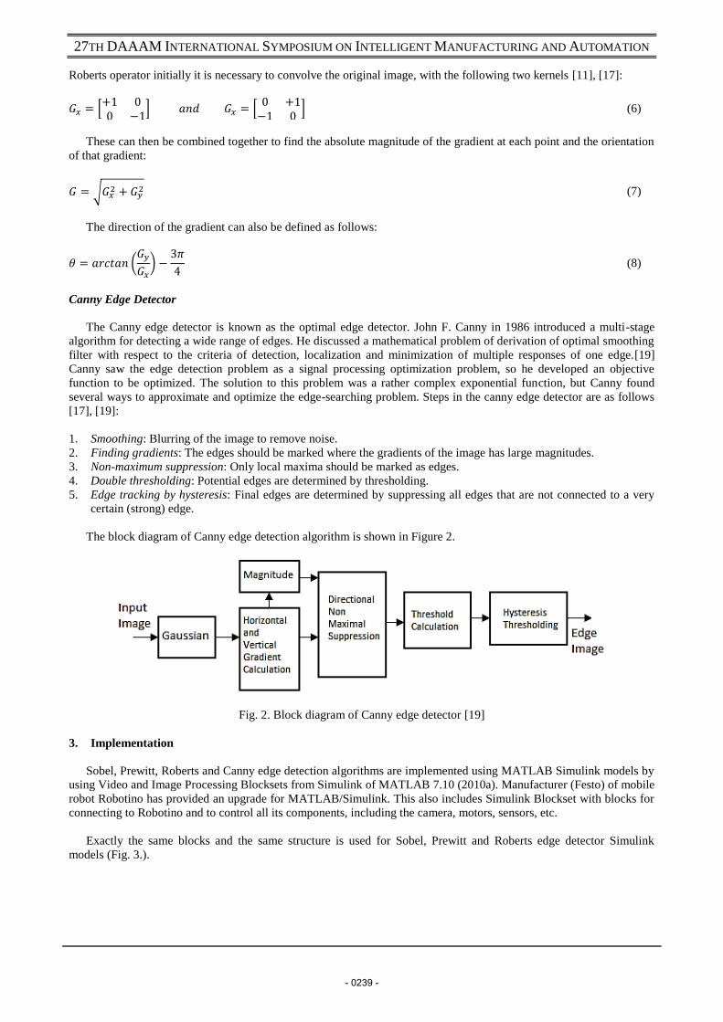
After testing on different scenes, it is possible to notice that the following parameters are most suitable:
Sobel, Prewitt and Roberts: TSF: 1 or 4 plus ET
Canny: APP: 95-97
Following images show detection of edges in the accordance with previously adopted parameters. These settings
provide the best edge detection of the obstacles that Robotino encounters.
Fig. 7. Edge detection - Obstacles: table and crosspiece; Room: moderately illuminated
Fig. 8. Edge detection - Obstacles: door, wall, doorstep; Room: very illuminated
Fig. 9. Edge detection - Obstacles: chair, closet, glass ashtray; Room: very illuminated
- 0242 -
27TH DAAAM INTERNATIONAL SYMPOSIUM ON INTELLIGENT MANUFACTURING AND AUTOMATION
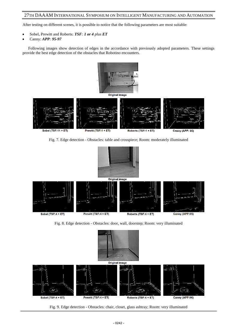
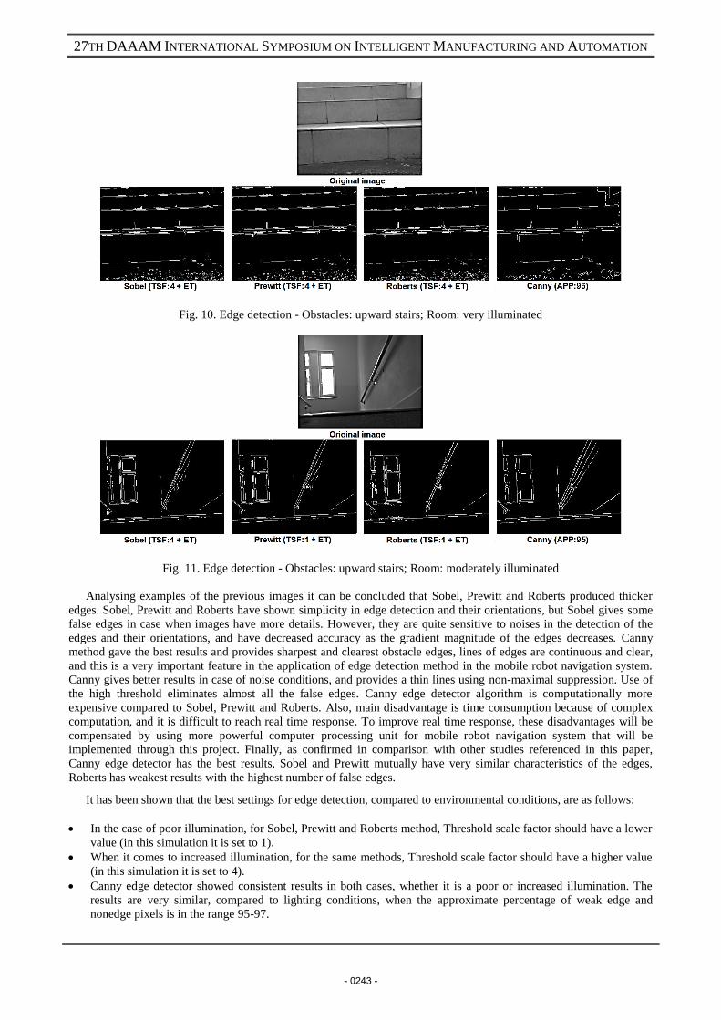
Fig. 10. Edge detection - Obstacles: upward stairs; Room: very illuminated
Fig. 11. Edge detection - Obstacles: upward stairs; Room: moderately illuminated
Analysing examples of the previous images it can be concluded that Sobel, Prewitt and Roberts produced thicker
edges. Sobel, Prewitt and Roberts have shown simplicity in edge detection and their orientations, but Sobel gives some
false edges in case when images have more details. However, they are quite sensitive to noises in the detection of the
edges and their orientations, and have decreased accuracy as the gradient magnitude of the edges decreases. Canny
method gave the best results and provides sharpest and clearest obstacle edges, lines of edges are continuous and clear,
and this is a very important feature in the application of edge detection method in the mobile robot navigation system.
Canny gives better results in case of noise conditions, and provides a thin lines using non-maximal suppression. Use of
the high threshold eliminates almost all the false edges. Canny edge detector algorithm is computationally more
expensive compared to Sobel, Prewitt and Roberts. Also, main disadvantage is time consumption because of complex
computation, and it is difficult to reach real time response. To improve real time response, these disadvantages will be
compensated by using more powerful computer processing unit for mobile robot navigation system that will be
implemented through this project. Finally, as confirmed in comparison with other studies referenced in this paper,
Canny edge detector has the best results, Sobel and Prewitt mutually have very similar characteristics of the edges,
Roberts has weakest results with the highest number of false edges.
It has been shown that the best settings for edge detection, compared to environmental conditions, are as follows:
In the case of poor illumination, for Sobel, Prewitt and Roberts method, Threshold scale factor should have a lower
value (in this simulation it is set to 1).
When it comes to increased illumination, for the same methods, Threshold scale factor should have a higher value
(in this simulation it is set to 4).
Canny edge detector showed consistent results in both cases, whether it is a poor or increased illumination. The
results are very similar, compared to lighting conditions, when the approximate percentage of weak edge and
nonedge pixels is in the range 95-97.
- 0243 -

27TH DAAAM INTERNATIONAL SYMPOSIUM ON INTELLIGENT MANUFACTURING AND AUTOMATION
5. Conclusion
This paper presents a Simulink models of Sobel, Prewitt, Roberts and the Canny edge detectors, used to compare the
quality of edges applied on detection of obstacle edges in navigation system of mobile robot. For mobile robot
navigation and detection of obstacles, it is very important that obstacles are visible, respectively, lines of edges must be
clear without false edges. Since edge detection is the initial step in obstacles detection and recognition, it is very
important to choose a method that will provide greatest number of correct data with least computational complexity. As
shown through the examples in this paper, Canny edge detector has the best results and it is able to provide sharpest and
clearest obstacle edges, with continuous and clear lines. Disadvantage of Canny method is computational complexities,
so it is necessary that robot has a powerful computer system in order to detect obstacles in the real time. Future work
will be focused on development of mobile robot navigation algorithm, which will be based on Canny edge detector.
6. References
[1] B. Crnokić and M. Grubišić, “Comparison of Solutions for Simultaneous Localization and Mapping for Mobile
Robot,” Proc. Fac. Mech. Eng. Comput. Univ. Most., p. 8, 2014
[2] A. Muraka, M. Sridahan, and B. Kuipers, “Detecting Obstacles and Drop-offs using Stereo and Motion Cues for
Safe Local Motion,” Intell. Robot. Syst. 2008. IROS 2008. IEEE/RSJ Int. Conf., pp. 702–708, 2008
[3] F. Shahdib and H. Mahmud, “Obstacle Detection and Object Size Measurement for Autonomous Mobile Robot
using Sensor,” Int. J. Comput. Appl., vol. 66, no. March 2013, pp. 28–33, 2013
[4] I. Ulrich and I. Nourbakhsh, “Appearance-Based Obstacle Detection with Monocular Color Vision,” Artif. Intell.,
no. August, pp. 866–871, 2000
[5] M. Iqbal, “Edge Detection for Mobile Robots on Lunar Surface and Surroundings,” BRAC University; Dhaka,
Bangladesh, 2012
[6] C. Gentsos, C. L. Sotiropoulou, S. Nikolaidis, and N. Vassiliadis, “Real-time canny edge detection parallel
implementation for FPGAs,” 2010 IEEE Int. Conf. Electron. Circuits, Syst. ICECS 2010 - Proc., pp. 499–502,
2010
[7] M. S. Guzel, “Mobile Robot Navigation using a Vision Based Approach,” Computer (Long. Beach. Calif)., 2003
[8] B. K. Balabantaray, P. Jha, and B. B. Biswal, “Application of edge detection algorithm for vision guided robotics
assembly system,” Sixth Int. Conf. Mach. Vis., no. November, pp. 1–7, 2013
[9] A. Q. Mahdi, G. A. QasMarrogy, and M. M. Ihassan, “Comparison of the Edge Detection Methods to Detect ,
Identify and Locate the Obstacles for Agricultural Robotic Vehicles,” Int. J. Res. Comput. Appl. Robot., vol. 2, no.
January, pp. 5–17, 2014
[10] P. S. Deokar, “Review on Distributed Canny Edge Detector using FPGA,” vol. 1, no. 4, pp. 37–45, 2014.
[11] R. Maini and H. Aggarwal, “Study and comparison of various image edge detection techniques,” Int. J. Image
Process. …, vol. 147002, no. 3, pp. 1–12, 2009
[12] B. Bansal, J. S. Saini, V. Bansal, and G. Kaur, “Comparison of Various Edge Detection Techniques,” J. Inf. Oper.
Manag., vol. 3, no. 1, pp. 103–106, 2012
[13] Festo Didactic, “Robotino-Workbook With CD-ROM Festo Didactic 544307 en.” Denkendorf, p. 124, 2012
[14] I. Breido, R. Markvardt, and A. Zarnitcin, “Modernization of Communication Interface Between Mobile Robot
Robotino and Matlab Software,” Ann. DAAAM 2012 Proc. 23rd Int. DAAAM Symp., vol. 23, no. 1, pp. 1107–
1110, 2012
[15] W. Lee, D. Kim, and I. Kweon, “Automatic edge detection method for the mobile robot application,” Intell. Robot.
Syst. 2003. (IROS 2003). Proceedings. 2003 IEEE/RSJ Int. Conf., vol. 3, pp. 2730–2735, 2003.
[16] P.H. Pawar R.P. Patil, “Image Edge Detection Techniques using MATLAB Simulink,” Int. J. Eng. Res. Technol.,
vol. 3, no. 6, pp. 2149–2153, 2014
[17] M.R. Rakesh, “Design and Simulation of Matlab / Simulink Model for Edge Detection Techniques in Image
Segmentation,” Int. J. Adv. Res. Electr. Electron. Instrum. Eng., vol. Vol. 2, no. Issue 12, pp. 5828–5834, 2013.
[18] N. H. Seng, “A comparison of various edge detection methods,” Seberang Perai, 2013
[19] N. M. Chaithra and K. V. R. Reddy, “Implementation of Canny Edge Detection Algorithm on FPGA and
displaying Image through VGA Interface,” no. 6, pp. 243–247, 2013
[20] B. Crnokić and S. Rezić, “Edge Detection for Mobile Robot using Canny method,” in 3rd International
Conference „NEW TECHNOLOGIES NT-2016 „Development and Application, 2016, pp. 106–111
[21] The MathWorks Inc, “Edge Detection,” Find edges of objects in images using Sobel, Prewitt, Roberts, or Canny
method. [Online]. Available: https://www.mathworks.com/help/vision/ref/edgedetection.html. [Accessed: 08-Mar-
2015]
[22] J. K. Sahu, P. R. Mishra, P. K. Sethy, and S. Behera, “Edge detection of a still image using simulation and real-
time implementation using TMS320C6713DSK,” UGC Spons. Natl. Semin. Emerg. Trends Inf. Technol. Dev., no.
March, 2014
- 0244 -