comparative study of rcc structure for earthquake load using light
TRANSCRIPT
International Research Journal of Engineering and Technology (IRJET) e-ISSN: 2395-0056
Volume: 02 Issue: 04 | July-2015 www.irjet.net p-ISSN: 2395-0072
© 2015, IRJET.NET- All Rights Reserved Page 1341
COMPARATIVE STUDY OF R.C.C STRUCTURE FOR EARTHQUAKE LOAD USING LIGHT WEIGHT BUILDING MATERIAL
Pooja K. Pardakhe1 Prof. M. R. Nalamwar2
1 M.E Student J.C.O.E.T, Yavatmal, INDIA. 2 Professor J.C.O.E.T, Yavatmal, INDIA.
--------------------------------------------------------------------------------------------------------------------------------------------------------
ABSTRACT :- Although building techniques and materials have evolved over thousands of years, construction is still a
long, complex, and expensive process. Construction industry boom can be seen in almost all the developing countries.
With the increase in material costs in the construction industry, there is a need to find more cost saving alternatives so
as to maintain the cost of constructing houses at prices affordable to people. There is need to develop an alternative
system of building component which would impart more benefits and are multifunctional with optimum use of labor and
material. This project presents brief analysis of building for G+4 & G+7 by using Red brick, CLC block and AAC block with
and without considering earthquake forces for zone III. Earthquake load calculation is also done for the structure in
which earthquake forces are considered. Cost analysis is made by using Red brick, CLC & AAC block and overall modeling
and analysis is done by using STAAD-Pro software to known the various bending moment and shear force acting on a
building. By using AAC block and CLC block the overall cost of construction is reduce and it will be safe and economical in
earthquake forces also.
Keywords: Affiliation fly ash, AAC brick, CLC brick.
INTRODUCTION:- A building can be defined as an
enclosed structure intended for human occupancy.
However, a building includes the structure itself and
nonstructural components (e.g., cladding, roofing,
interior walls and ceilings, HVAC systems, electrical
systems) permanently attached to and supported by
the structure. The scope of the provisions provides
recommended seismic design criteria for all buildings
except detached one- and two-family dwellings located
in zones of relatively low seismic activity and
agricultural structures (e.g., barns and storage sheds)
that are only intended to have incidental human
occupancy. The provisions also specify seismic design
criteria for nonstructural components in buildings that
can be subjected to intense levels of ground shaking.
The structure in high seismic areas may be susceptible
and efficient to severe damage. Along with gravity load
structure has to withstand to lateral load which can
develop high stresses. Now a days, light weight
structures system is also used to resist lateral load due
to earthquake, wind etc. the light building reduces the
self weight of the structure and hence the lateral load
acting on the building is also reduced. Conventional
construction utilizes structural members that depend
on size for their strength. The greater the span for a
structural member the larger it has to be to support to a
given load. Lightweight construction does not derive its
strength from their size and obtained from multiple

International Research Journal of Engineering and Technology (IRJET) e-ISSN: 2395-0056
Volume: 02 Issue: 04 | July-2015 www.irjet.net p-ISSN: 2395-0072
© 2015, IRJET.NET- All Rights Reserved Page 1342
members that are in compression and in tension. And it
also reduces the mass/ span ration. The light weight
building materials are AAC bricks, rapid walls, fabric
materials and other alternative material are also
available in market. Autoclaved Aerated Concrete (AAC)
is a certified green building material, which can be used
for commercial, industrial and residential construction.
It is porous, non-toxic, reusable, renewable and
recyclable. AAC block are solid units they weigh about
half a normal brick Makes productive use of recycled
industrial waste (fly ash). Non-polluting manufacturing
process, does not exude gases, total energy
consumption for producing Biltech ACE is less than ½
of what it takes to produce other building material
In this, system will compare R.C.C structure and light weight R.C.C structure by using alternative light weight building material (AAC, CLC bricks). Both the structures are of G+4 & G+7 commercial building with same grid and the building are located in same earthquake zones i.e. Zone III (IS-1893-2002) and live load on both the building is same as per IS-875 part 2. The parameter user has studied is to investigate the, 1) Bending moment, shear force, torsion, axial load 2) Cost of the building 3) Construction time 4) Earthquake loads 5) Carbon emission Detailed analysis and design of a building for different earthquake zones will be done by Computer aided analysis software i.e. (STAAD-pro) where cost estimation will be carried out using MS-Excel programming. From obtained results system will compare all the parameters between R.C.C structure and light weight R.C.C structure. ANALYSIS REPORT After applying all the loads acting on a building we will get the analysis values of bending moment in a beam and axial load on column. After knowing the analysis results user will finalize the section for beam and column. For sample finalization of the section of beam and column for their respective bending moments and axial load we take two frame i.e. Frame-F (for beam section) & Frame-2 (For column section) of Model-A & Model-F i.e. Frame-F is in X-direction & Frame-02 is in Z- direction as shown in figure no.6.1.
Figure 1: PLAN
MODEL – A (FRAME –F)
Figure 2: shows the beam number and node number
for frame-F

International Research Journal of Engineering and Technology (IRJET) e-ISSN: 2395-0056
Volume: 02 Issue: 04 | July-2015 www.irjet.net p-ISSN: 2395-0072
© 2015, IRJET.NET- All Rights Reserved Page 1343
Figure 4: BENDING MOMENT GRAPH FOR
After the analysis process is done we get bending moment and axial load values and diagram as shown in figure 6.3. For example:- we take a beam no 35 for finalization on beam section. Figure 6.4 shows the maximum bending moments on beam 35 i,e B.M = 117 kn/m Sample calculation for beam:- FRAME -F THE MAXIMUM BENDING MOMENT IS = 117 KN/M ASSUME width of beam (b) = 300mm Therefore,
d =
=
d = 375 mm CLEAR COVER for beam = 20 mm D = 375+20 D = 395 mm D = 450 mm For B.M = 117 kn/m the beam section finalized is 300 mm x 450mm.And same beam section is assign to beam35 in model processing. Refer the beam table in with for beam no. 35 the 6 no property is assign. And in section properties table property no.06 is Rect 0.3 x 0.45 mm. Hence assign property is correct. And in similar manner all the beam section are calculated and assign to respective beam in the frame. MODEL-A (Frame -02)
Figure 5: BEAM & NODE NUMBER FOR FRAME -2
Figure 6: B.M – S.F DIAGRAM FOR FRAME-2

International Research Journal of Engineering and Technology (IRJET) e-ISSN: 2395-0056
Volume: 02 Issue: 04 | July-2015 www.irjet.net p-ISSN: 2395-0072
© 2015, IRJET.NET- All Rights Reserved Page 1344
Figure 7: AXIAL LOAD ON NODE 170 After the analysis process is done we get bending moment and axial load values and diagram as shown in figure 6.6. For example:- we take a node no 170 for finalization on column section. Figure 6.7 shows the maximum axial load on column 170 i,e Pu = 4485 kn SAMPLE CALCULATION:- The axial load on the node 170 is, Pu= 4496 KN ASSUMING 1% OF STEEL Area of longitudinal reinforcement of column is ASC= 0.01 Ag Area of concrete is Ac= Ag-Asc = Ag-0.015Ag = 0.999 Ag Using clause of IS -456:2000 Pu = 0.4xFck x Ac+0.67 X Fy X Asc-0.4 X Fck X Asc 4496X10^3 = 0.4 X 20 X 0.999Ag + 0.67x415x0.01Ag-0.4x20x0.01Ag Ag= 419452.88 mm^2 ASSUME b= 500mm Ag = b X D 383546.71 = 500 X D D= 838.90 mm D= 850 mm For axial load = 4485 kn the column section finalized is 500 mm x 850mm.And same column section is assign to column 170 in model processing. Refer the beam table in with for beam no 170 the 2 no property is assign. And in section properties table property no.06 is Rect 0.5 x 0.85 mm. Hence assign property is correct. And in similar manner all the column section are calculated and assign to respective beam in the frame. AAC DYNAMIC (F-02)
6 Figure 8: B.M – S.F DIAGRAM FOR FRAME-2 6.2 RESULTS AND DISCUSSION
6.3 6.2.1 BENDING MOMENTS FOR BEAM NO 35
Figure 9: B.M FOR MODEL- A
Figure 10: B.M FOR MODEL- B
International Research Journal of Engineering and Technology (IRJET) e-ISSN: 2395-0056
Volume: 02 Issue: 04 | July-2015 www.irjet.net p-ISSN: 2395-0072
© 2015, IRJET.NET- All Rights Reserved Page 1345
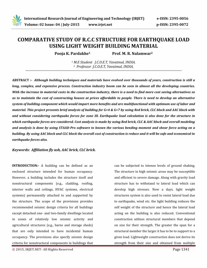
Figure 11: B.M FOR MODEL- C
Figure 12: B.M FOR MODEL- D(ENVALOPE)
Figure 13: B.M FOR MODEL- E ENVALOPE)
Figure 15: B.M FOR MODEL- F (ENVALOPE)
Table 1: +VE & -VE BM VALUES FOR BEAM NO.35
After getting the results of bending moment for beam no35, we observed that the Bending moment for model – A is 117 Kn/m and it reduces to 84.3 Kn/m for model-B. From that we can say that as the material change i.e. RB changes by CLC brick bending moment occur in beam is less as compare to RB and simultaneously the section required for model-B is less than model-A. Similarly, the bending moment for model- C is also less i.e. 74..3 Kn/m which is less than model-A & model-B. Hence the section required for beam is also less. For earthquake design also we observed the same think that is the bending moment for model-D is greater as compare to model-E & model-F.
6.2.2 AXIAL LOAD FOR NODE 170
Figure 16: AXIAL LOAD FOR MODEL-B
Figure 17: AXIAL LOAD FOR MODEL -A
MODEL A B C D E F +VE B.M
117 84.3 79.1 218 180 176
-VE BM 63.1 47 44.5 79.3 75.2 74.9

International Research Journal of Engineering and Technology (IRJET) e-ISSN: 2395-0056
Volume: 02 Issue: 04 | July-2015 www.irjet.net p-ISSN: 2395-0072
© 2015, IRJET.NET- All Rights Reserved Page 1346
Figure 18: AXIAL LOAD FOR MODEL-C
Figure 19: AXIAL LOAD FOR MODEL- D
Figure 20: AXIAL LOAD FOR MODEL-E
Figure 21: AXIAL LOAD FOR MODEL- F
Table 2: AXIAL LOADS
MODEL A B C D E F
Pu 4510 3884 3791 4576 3869 3783
After getting the results of axial load for node no 170, we observed that the axial load for model – A is 4510 Kn and it reduces to 3884 Kn for model-B. From that results we can say that as the material change i.e. RB changes by CLC brick the axial load occur in column is less as compare to RB and simultaneously the section required for model-B is less than model-A. Similarly, the axial load for model- C is also less i.e. 3791 Kn which is less than model -A & model-B. Hence the section required for beam is also less. For earthquake
design also we observed the same think that is the bending moment for model-D is greater as compare to model-E & model-F. 7.2 RESULTS & DISCUSSION:-
GRAPH NO.1 :- QUANTITY OF CONCRETE FOR G+7
GRAPH NO.2 :- QUANTITY OF CONCRETE FOR G+4
International Research Journal of Engineering and Technology (IRJET) e-ISSN: 2395-0056
Volume: 02 Issue: 04 | July-2015 www.irjet.net p-ISSN: 2395-0072
© 2015, IRJET.NET- All Rights Reserved Page 1347
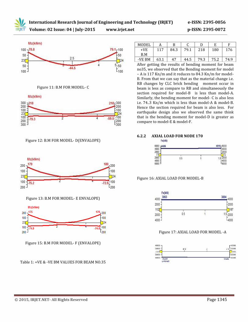
GRAPH NO.3 :- OVERALL COST FOR G+7
GRAPH NO. 4 :- OVERALL COST FOR G+4
GRAPH NO. 5 :- TOTAL FRAME COST FOR G+7
GRAPH NO. 6 :- TOTAL FRAME COST FOR G+4

International Research Journal of Engineering and Technology (IRJET) e-ISSN: 2395-0056
Volume: 02 Issue: 04 | July-2015 www.irjet.net p-ISSN: 2395-0072
© 2015, IRJET.NET- All Rights Reserved Page 1348
GRAPH NO. 7 :- OVERALL COST Rs/ M2 FOR G+7
GRAPH NO. 8 :- OVERALL COST Rs/M2 FOR G+4
GRAPH NO. 8 :- FRAME COST Rs/M2 FOR G+7
GRAPH NO. 9 :- FRAME COST Rs/M2 FOR G+4
From the above graph we will observed that
the overall cost for a building by using rb is greater as
compare to the AAC & CLC brick. in AAC block there will
be a 33% overall cost is reduced as compare to RB. And
in CLC block the 25% overall is ccost is reduce as
compare to the RB.
By using AAC blocks & CLC blocks their will be a consumsion on concrete and steel as compare to RB. In AAc block 20% concrete and steel will be consumed than that of RB & in CLC block 25% of concrete and steel is consumed than that of RB. Hence there will be a less carbon emission in the environment. Hence use of light weight block in a construction is economical and time saving.
International Research Journal of Engineering and Technology (IRJET) e-ISSN: 2395-0056
Volume: 02 Issue: 04 | July-2015 www.irjet.net p-ISSN: 2395-0072
© 2015, IRJET.NET- All Rights Reserved Page 1349
CONCLUSION
1. As per the observation of bending moment diagram,it is found that the bending moment in model B & C loaded with light weight material without earthquake load is reduced by 33.8% and 38 % as compare to model-A loaded with RB respectively.
2. For model- E & F loaded with light weight material with earthquake load, Bending moment and shear force is also reduced as compare to model-D loaded with RB with earthquake load.
3. As per IS standard 1893, part 1, 2002, earthquake load calculation using Red brick and light weight is done. It is observed that base shear for Red brick is greater as compare to the light weight brick by 22.5 %.
4. Total Cost of R.C.C frame loaded with Red brick is Rs.26291696.8 and for AAC block is Rs.20439279.62 which is less as compare to the Red brick.
5. For G+4 R.C.C. Frame cost of Red Brick is Rs.3208/- Sqmtr and for AAC block cost is Rs.2921.18/ Sqmtr ,which is 9% less.
6. For G+7 R.C.C Frame cost of red brick is Rs 2900 / sqmtr and for AAC block cost is Rs. 2601.2 /sqmtr, which is 10 % less.
7. The cost of per mtr sqr of G+4 structure is more as compared to G+7 structure.
8. Hence AAC block masonry was found to be economical as compared to conventional Red brick for static and Earth quake loading.
9. Due to reduction of concrete consumption and steel consumption carbon foot prints are reduced.
10. Due to less thermal conductivity of AAC block, internal environment of construction will be cool and will requires less energy for cooling and heating.As per the observation of bending moment diagram,it is found that the bending moment in model B & C loaded with light
weight material without earthquake load is reduced as compare to model-a loaded with RB.
11. Similarly for model- E & F loaded with light weight material with earthquake load is also reduced as compare to model-D loaded with RB with earthquake load.
LIMITATIONS
This project is limitated for the following:-
1) Grade of concrete is M-20 and steel is Fe-415
2) For earthquake zone-III
3) For G+4 & G+7 building
SCOPE OF FUTURE STUDY
In this project Comparative study of R.C.C
structure for earthquake load using light weight
building material for G+4 & G+7 in zone III by using M-
20 concrete & Fe-415 steel is done. This project can be
used in future by changing floors of building, also
change the zone of earthquake. And design is also done
for building.
References
1 Design of Reinforced Concrete Structures by A. K. Jain
2 Illustrated design of reinforced concrete buildings by Dr.V.L. Shah & Dr.S.R.Karve
3 Basic Principles of Analysis and Design of an RCC Framed Structures by Prof. H. R. Surya Prakash S. Krishna Murthy
4 Design of R.C.C structural elements by S.S. Bhavikatti
5 Design of R.C.C slabs by K.C.Jain 6 R.C.C Design and Drawing by Neelam Sharma 7 Treasure of R.C.C Designs by Sushil kumar 8 Design of R.C.C structures by prof.N.Krishna Raju 9 Design of R.C.C structures by prof.S.Ramamrutham 10 R.C.C design by S.Unnikrishina pillai & Devdas
Menon
11 APTICO Limited, Project Profile For Cellular Light Weight Concrete (CLC) & Sand Lime Brick
12 Narendra Taly (2010), DESIGN OF REINFORCED MASONRY STRUCTURE S, Second Edition New McGraw-Hill New York, Professor Emeritus Department of Civil Engineering California State University, Los Angeles.
International Research Journal of Engineering and Technology (IRJET) e-ISSN: 2395-0056
Volume: 02 Issue: 04 | July-2015 www.irjet.net p-ISSN: 2395-0072
© 2015, IRJET.NET- All Rights Reserved Page 1350
13 The code books referred for this project are: IS 456:2000 (reinforced concrete for general building construction) IS 875, part 1, 1987(dead loads for building and structures) IS 875, part 2, 1987(imposed loads for buildings and structures) SP 16 (design aids for IS 456), IS-2145 (AAC BLOCK)
14 APTICO Limited, Project Profile For Cellular Light Weight Concrete (CLC) & Sand Lime Brick
15 www.brickwell.co.in 16 Agus Setyo Muntohar, (2011), Engineering
characteristics of the compressed-stabilized earth brick, Construction and Building Materials, Elsevire, vol – 25, pp – 4215-4220.
17 Alex Liew, Mazhar ul Haq, Light Weight/Low Cost Construction Methods For Developing Countries, CBM-CI International Workshop, Karachi, Pakistan, pp – 491-504.
18 B. V. Venkatarama Reddy, (Feb 2007), Richardson Lal, and K. S. Nanjunda Rao, Enhancing Bond Strength and Characteristics of Soil-Cement Block Masonry, Journal Of Materials In Civil Engineering, ASCE, Vol. – 19, pp – 164- 172.
19 K. B. Anand and K. Ramamurthy, (May-June 2003), Laboratory-Based Productivity Study on Alternative Masonry Systems, Journal Of Construction Engineering And Management ASCE, volume/issue-129, pp – 237-242
20 Agus Setyo Muntohar, (2011), Engineering characteristics of the compressed-stabilized earth brick, Construction and Building Materials, Elsevire, vol – 25, pp – 4215-4220.
21 Alex Liew, Mazhar ul Haq, Light Weight/Low Cost Construction Methods For Developing Countries, CBM-CI International Workshop, Karachi, Pakistan, pp – 491-504.
22 B. V. Venkatarama Reddy, (Feb 2007), Richardson
Lal, and K. S. Nanjunda Rao, Enhancing Bond Strength and Characteristics of Soil-Cement Block Masonry, Journal Of Materials In Civil Engineering, ASCE, Vol. – 19, pp – 164- 172.
23 K. B. Anand and K. Ramamurthy, (May-June 2003), Laboratory-Based Productivity Study on Alternative Masonry Systems, Journal Of Construction Engineering And Management ASCE, volume/issue-129, pp – 237-242.
24 Krishna Bhavani Siram, (Dec 2012), Cellular Light-Weight Concrete Blocks as a Replacement of Burnt Clay Bricks, International Journal of Engineering and Advanced Technology (IJEAT) ISSN: 2249 – 8958, Volume-2, Issue-2, pp – 149- 151.
25 Mucahit Sutcu, Juan José del Coz Díaz, Felipe Pedro Álvarez Rabanal, Osman Gencel, Sedat Akkurt, (Feb 2014) Thermal performance optimization of hollow clay bricks made up of paper waste, Energy and Building ELSEVIER, Vol. – 75, pp – 96-108.
26 INDIGENOUS EARTHQUAKE-RESISTANT TECHNOLOGIES 13th World Conference on Earthquake Engineering Vancouver, B.C., Canada August 1-6, 2004 Paper No. 5053
27 GLASS FIBRE REINFORCED GYPSUM LOAD BEARING (GFRG) PANELS FOR AFFORDABLE HOUSING IN FAST TRACK & ENVIRONMENTAL PROTECTION