comparative study of electrochemical performances of the as-melt mg20ni10−xmx (m=none, cu, co, mn;...
TRANSCRIPT
Journal of Alloys and Compounds 555 (2013) 131–137
Contents lists available at SciVerse ScienceDirect
Journal of Alloys and Compounds
journal homepage: www.elsevier .com/locate / ja lcom
Comparative study of electrochemical performances of the as-meltMg20Ni10�xMx (M = None, Cu, Co, Mn; x = 0, 4) alloys applied to Ni/metalhydride (MH) battery
Yanghuan Zhang a,b,⇑, Chen Zhao a,b, Tai Yang a,b, Hongwei Shang a,b, Chao Xu a,b, Dongliang Zhao b
a Key Laboratory of Integrated Exploitation of Baiyun Obo Multi-Metal Resources, Inner Mongolia University of Science and Technology, Baotou 014010, PR Chinab Department of Functional Material Research, Central Iron and Steel Research Institute, Beijing 100081, PR China
a r t i c l e i n f o a b s t r a c t
Article history:Received 29 October 2012Received in revised form 3 December 2012Accepted 6 December 2012Available online 12 December 2012
Keywords:Mg2Ni-type alloyElement substitutionMelt spinningNanocrystalline and amorphousElectrochemical characteristics
0925-8388/$ - see front matter � 2012 Elsevier B.V. Ahttp://dx.doi.org/10.1016/j.jallcom.2012.12.016
⇑ Corresponding author at: Department of FunctionIron and Steel Research Institute, 76 Xueyuan Nan R100081, PR China. Tel.: +86 010 62183115; fax: +86 0
E-mail address: [email protected] (Y. Zhang).
The partial substitution of M (M = Cu, Co, Mn) for Ni has been performed in order to ameliorate the elec-trochemical hydrogen storage performances of Mg2Ni-type electrode alloys. The melt spinning technol-ogy was used to prepare the Mg20Ni10�xMx (M = None, Cu, Co, Mn; x = 0, 4) electrode alloys. The impactsof the melt spinning and the M (M = Cu, Co, Mn) substitution on the structures and electrochemicalhydrogen storage characteristics of the alloys were investigated systemically. The analysis of XRD andTEM reveals that the as-spun (M = None, Cu) alloys display an entire nanocrystalline structure, whereasthe as-spun (M = Co, Mn) alloys hold a nanocrystalline/amorphous structure, indicating that the substi-tution of M (M = Co, Mn) for Ni facilitates the glass formation in the Mg2Ni-type alloys. Besides, all the as-cast alloys have a major phase Mg2Ni, whereas the M (M = Co, Mn) substitution brings on the formationof some secondary phases, MgCo2 and Mg for the (M = Co) alloy, and MnNi and Mg for the (M = Mn) alloy.Based upon the electrochemical measurements, an evident impact engendered by melt spinning on theelectrochemical performances of the alloys appears. The cycle stability of the alloys augments monoto-nously with the growing of the spinning rate. The discharge capacity and high rate discharge ability(HRD), however, act differently. Melt spinning enhances the cycle stability of the (M = Co, Mn) alloys dra-matically, but exerts an adverse impact on the (M = None, Cu) alloys. The high rate discharge ability(HRD) of all the alloys grow considerably with the rising of the spinning rate except for (M = Mn) alloy,whose HRD has a maximum value with the variation of the spinning rate. Furthermore, the substitutionof M (M = Cu, Co, Mn) for Ni enhances the electrochemical performances of the as-cast and spun Mg2Nialloys evidently, but the M (M = Mn) substitution gives rise to a decline of HRD when the spinning ratereaches 20 m/s.
� 2012 Elsevier B.V. All rights reserved.
1. Introduction
Mg2Ni-type metallic hydrides are looked upon as one of themost promising negative electrodes applied to Ni-MH batteries[1,2] or hydrogen storage materials because of their major advan-tages, such as the theoretical electrochemical capacity being1000 mAh/g and gaseous hydrogen absorption capacity being3.6 wt.% for Mg2NiH4 [3,4]. However, the practical application ofthese alloys is deeply frustrated by their relatively high hydro-gen-desorption temperatures, sluggish hydriding/dehydridingkinetics as well as extremely poor electrochemical cycle stability.In fact, the specific capacity and hydriding/dehydriding kineticsof hydride electrode materials depend on their chemical composi-
ll rights reserved.
al Material Research, Centraload, Haidian District, Beijing10 62187102.
tion and crystalline structure [5,6]. It was documented that Mg andMg-based hydrogen storage alloys with a nanocrystalline/amor-phous structure exhibit higher hydrogen-absorption capacity andfaster hydriding/dehydriding kinetics than crystalline Mg2Ni [7].
High energy ball-milling (HEBM) is undoubtedly deemed to be aquite effective method for preparing nanocrystalline/amorphousMg and Mg-based alloys [8]. However, the milled Mg and Mg-based alloys exhibit rather poor cycle stability owing to the vanish-ment of the metastable structures formed by ball milling duringthe multiple electrochemical charging and discharging cycles [9],which is an insurmountable barrier for its practical application aselectrode materials. Alternatively, the melt spinning techniquenot only overcomes the aforementioned shortcomings but alsoprohibits the rapid degradation of the hydrogen absorbing/desorb-ing cyclic characteristics of Mg and Mg-based compounds [10].Huang et al. [11] reported that the nanocrystalline/amorphous(Mg60Ni25)90Nd10 alloy prepared by melt spinning yields its highestdischarge capacity of 580 mAh/g. Spassov and Köster [12] prepared

132 Y. Zhang et al. / Journal of Alloys and Compounds 555 (2013) 131–137
Mg63Ni30Y7 hydrogen storage alloy by rapid solidification process,obtaining a maximum hydrogen absorption capacity of about3.0 wt.%. In addition, the as-spun Mg2(Ni, Y) alloys demonstratedan enhanced hydriding kinetics compared to the conventionallyprepared polycrystalline Mg2Ni alloys, even comparable to thatof the ball-milled nanocrystalline Mg2Ni.
It was documented that the partial substitution of some ele-ments (Cu, Fe, V, Cr, Co) for Ni in Mg2Ni compound decreases thestability of the hydride and makes the desorption reaction easier[13,14]. Besides, such substitution facilitates the glass forming ofthe Mg2Ni alloy. In which a single amorphous phase can be ob-tained by adding a small amount of La, Y or Nd [11]. Based on theseresults, the present investigation is focused on the influences ofsubstituting M (M = Cu, Co, Mn) for Ni and melt spinning on thestructure and electrochemical hydrogen storage performances ofMg2Ni-type alloys. In this study, the Mg2Ni-type Mg20Ni10�xMx
(M = None, Cu, Co, Mn; x = 0, 4) alloys were synthesized by meltspinning technology. Afterwards, we made a general comparisonof the impacts on the structure and the electrochemical perfor-mances generated by element substitution and melt spinning.
2. Experimental
The compositions of the experimental alloys were Mg20Ni10-xMx (M = Cu, Co,Mn; x = 0, 4). The alloy ingots were prepared by using a vacuum induction furnacein a helium atmosphere at a pressure of 0.04 MPa to prevent Mg from volatilizing. Apart of the as-cast alloys was re-melted and spun by melt spinning with a rotatingcopper roller cooled by water. The spinning rates used in the experiment were 15,20, 25 and 30 m/s, respectively, which were approximately expressed by the linearvelocity of the copper roller.
The phase structures of the as-cast and spun alloys were determined by X-raydiffraction (XRD) (D/max/2400). The diffraction, with the experimental parametersof 160 mA, 40 kV and 10�/min respectively, was performed with CuKa1 radiation fil-tered by graphite.
The thin film samples of the as-spun alloys prepared by using ion etching tech-nology were observed by high resolution transmission electron microscope(HRTEM) (JEM-2100F, operated at 200 kV).
The as-cast and spun alloy powders ground mechanically was filtered by a sievewith the mesh of 20 lm. The alloy powder and carbonyl nickel powder were mixedin a weight ratio of 1:4. The mixture was cold pressed under a pressure of 35 MPainto round electrode pellets with 15 mm in diameter and 1 g in weight.
Fig. 1. XRD profiles of the as-cast and spun Mg20Ni10�xMx (M = None,
The electrochemical measurements were performed at 30 �C by using a tri-elec-trode open cell consisting of a working electrode (the metal hydride electrode), asintered Ni(OH)2/NiOOH counter electrode as well as a Hg/HgO reference electrode,which were immersed in 6 M KOH electrolyte. The voltage between the negativeelectrode and the reference one was defined as the discharge voltage. In every cycle,the alloy electrode was first charged with a constant current density, after restingfor 15 min, it was discharged at the same current density to cut-off voltage of�0.500 V.
The electrochemical impedance spectra (EIS) and the Tafel polarization curvesof the alloys were measured by an electrochemical workstation (PARSTAT 2273).The fresh electrodes were fully charged and then rested for 2 h up to the open cir-cuit potential stabilization. For the EIS measurement, the frequency ranged from10 kHz to 5 mHz at 50% depth of discharge (DOD), the amplitude of signal potentio-static or galvanostatic measurements being 5 mV, the number of points per decadeof frequencies being 60. For the Tafel polarization curves, the potential range was�1.2 to +1.0 V (vs. Hg/HgO) with a scan rate of 5 mV/s. For the potentiostatic dis-charge, the test electrodes in the fully charged state were discharged at 500 mV po-tential steps for 3500 s on electrochemical workstation (PARSTAT 2273), using theelectrochemistry corrosion software (CorrWare).
3. Results and discussion
3.1. Microstructure characteristics
Fig. 1 depicts the XRD profiles of the as-cast and spun Mg20-
Ni10�xMx (M = None, Cu, Co, Mn; x = 0, 4) alloys. The as-cast(M = None, Cu) alloys hold a single phase structure, whereas the(M = Co, Mn) alloys have secondary phases, being MgCo2 and Mgfor the former, MnNi and Mg for the latter, indicating that suchsubstitution generates secondary phases. Also, the diffractionpeaks of the as-spun (M = None, Cu) alloys display an entire crystalstructure, while the peaks of the as-spun (M = Co, Mn) alloys aremuch broader around 40� ascribed to the mixture of nanocrystal-line/amorphous structure, suggesting that the substitution of M(M = Co, Mn) for Ni facilitates the glass formation in the Mg2Ni-type alloy.
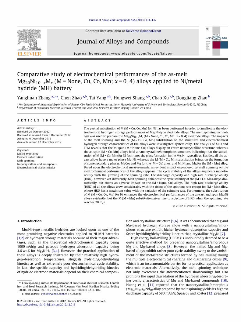
Fig. 2 demonstrates the TEM micrographs of the as-spun (30 m/s) Mg20Ni10�xMx (M = None, Cu, Co, Mn; x = 0, 4) alloys. Evidently,the as-spun (M = None, Cu) alloys exhibit a nanocrystalline struc-ture, and some crystal defects such as sub-grains and grain bound-aries can be seen clearly from the amplified morphologies of
Cu, Co, Mn; x = 0, 4) alloys: (a) as-cast and (b) as-spun (30 m/s).
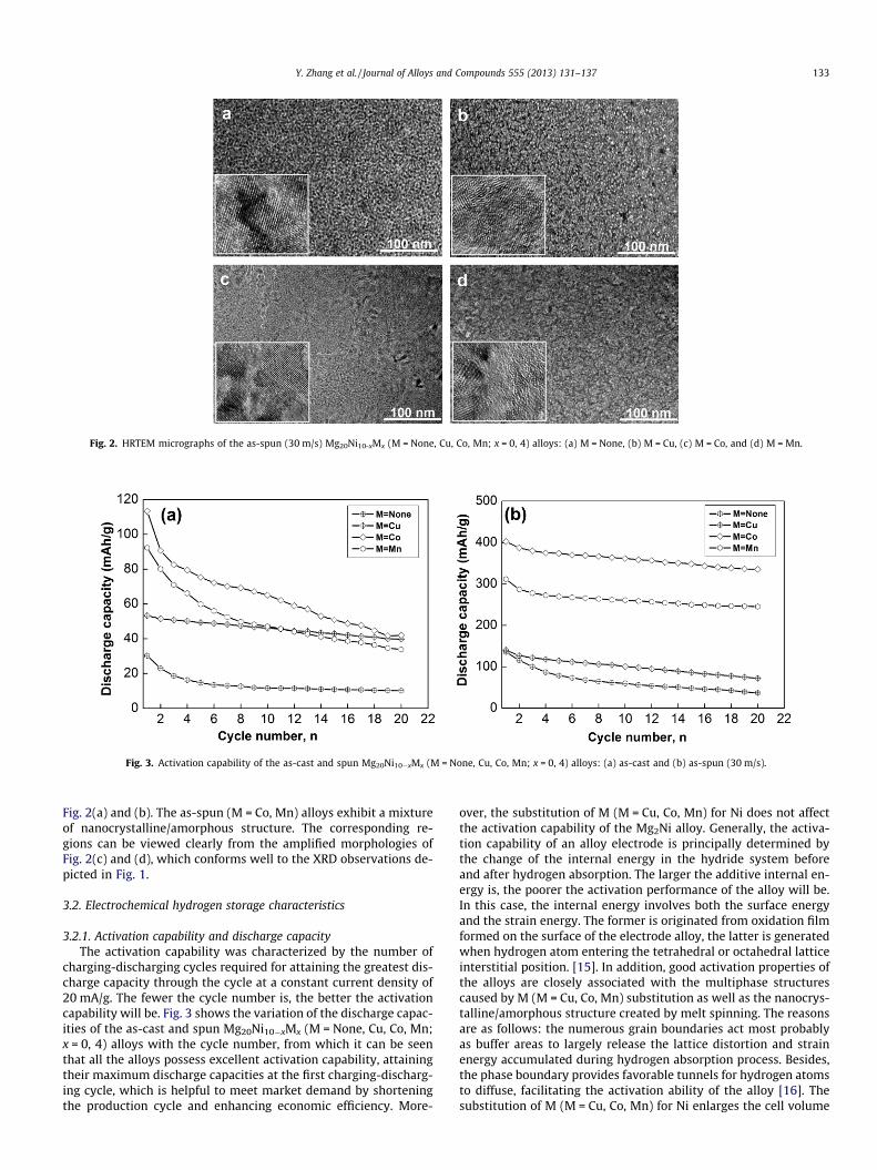
Fig. 2. HRTEM micrographs of the as-spun (30 m/s) Mg20Ni10-xMx (M = None, Cu, Co, Mn; x = 0, 4) alloys: (a) M = None, (b) M = Cu, (c) M = Co, and (d) M = Mn.
Fig. 3. Activation capability of the as-cast and spun Mg20Ni10�xMx (M = None, Cu, Co, Mn; x = 0, 4) alloys: (a) as-cast and (b) as-spun (30 m/s).
Y. Zhang et al. / Journal of Alloys and Compounds 555 (2013) 131–137 133
Fig. 2(a) and (b). The as-spun (M = Co, Mn) alloys exhibit a mixtureof nanocrystalline/amorphous structure. The corresponding re-gions can be viewed clearly from the amplified morphologies ofFig. 2(c) and (d), which conforms well to the XRD observations de-picted in Fig. 1.
3.2. Electrochemical hydrogen storage characteristics
3.2.1. Activation capability and discharge capacityThe activation capability was characterized by the number of
charging-discharging cycles required for attaining the greatest dis-charge capacity through the cycle at a constant current density of20 mA/g. The fewer the cycle number is, the better the activationcapability will be. Fig. 3 shows the variation of the discharge capac-ities of the as-cast and spun Mg20Ni10�xMx (M = None, Cu, Co, Mn;x = 0, 4) alloys with the cycle number, from which it can be seenthat all the alloys possess excellent activation capability, attainingtheir maximum discharge capacities at the first charging-discharg-ing cycle, which is helpful to meet market demand by shorteningthe production cycle and enhancing economic efficiency. More-
over, the substitution of M (M = Cu, Co, Mn) for Ni does not affectthe activation capability of the Mg2Ni alloy. Generally, the activa-tion capability of an alloy electrode is principally determined bythe change of the internal energy in the hydride system beforeand after hydrogen absorption. The larger the additive internal en-ergy is, the poorer the activation performance of the alloy will be.In this case, the internal energy involves both the surface energyand the strain energy. The former is originated from oxidation filmformed on the surface of the electrode alloy, the latter is generatedwhen hydrogen atom entering the tetrahedral or octahedral latticeinterstitial position. [15]. In addition, good activation properties ofthe alloys are closely associated with the multiphase structurescaused by M (M = Cu, Co, Mn) substitution as well as the nanocrys-talline/amorphous structure created by melt spinning. The reasonsare as follows: the numerous grain boundaries act most probablyas buffer areas to largely release the lattice distortion and strainenergy accumulated during hydrogen absorption process. Besides,the phase boundary provides favorable tunnels for hydrogen atomsto diffuse, facilitating the activation ability of the alloy [16]. Thesubstitution of M (M = Cu, Co, Mn) for Ni enlarges the cell volume

Fig. 4. Evolution of the discharge capacity of the Mg20Ni10�xMx (M = None, Cu, Co,Mn; x = 0, 4) alloys with the spinning rate.
134 Y. Zhang et al. / Journal of Alloys and Compounds 555 (2013) 131–137
and lowers the expansion/contraction ratio of the alloys duringhydrogen absorption and desorption process, which cause a de-crease of the strain energy as stated by our previously publishedworks [17,18].
Fig. 4 describes the variations of the maximum discharge capac-ities of the Mg20Ni10-xMx (M = None, Cu, Co, Mn; x = 0, 4) alloysdepending on the spinning rate. Evidently, for each alloy, the dis-charge capacity grows with the rising of the spinning rate dramat-ically. Furthermore, melt spinning engenders a more distinguishedimprovement on the discharge capacity of the (M = Co, Mn) substi-tuted alloys compared to the (M = None, Cu) substituted alloys.Whatever the spinning rate is, the discharge capacities are in se-quence: (M = Co) > (M = Mn) > (M = Cu) > (M = None), showing thatM (M = Cu, Co, Mn) substitution brings on a positive impact on thedischarge capacity of Mg2Ni alloy. Some elucidations can be offeredcorresponding to the preceding results. The observed variations ofthe discharge capacity of alloys, induced by melt spinning, are def-initely associated with their microstructure change. Firstly, thecrystalline material, when melt spun, becomes at least partiallydisordered and its structure changes into nanocrystalline or amor-phous. As a result, a large number of interfaces and grain bound-aries appear in the nanocrystalline materials, which contributespositively to the discharge capacity due to the fact that the grainboundaries possess the distribution of the maximum hydrogenconcentrations [19]. Secondly, the nanocrystalline structure gener-
Fig. 5. Evolution of the capacity retaining rates (Sn) of the as-cast and spun Mg20Ni10
ated by melt spinning evidently promotes the hydriding anddehydriding abilities of Mg2Ni-type alloys [20]. The positive contri-bution of M (M = Cu, Co, Mn) substitution for Ni to the dischargecapacity of the alloy is generally attributed to the following as-pects. On the one hand, the visibly refined grains by M (M = Cu,Co, Mn) substitution and the facilitated glass forming process byM (M = Co, Mn) substitution result in such positive impact becausean adequate proportion of amorphous and nanocrystalline in Mg-Ni-based alloy possesses superior discharge property [12]. On theother hand, the secondary phases Mg2Cu [21], MgCo2 and MnNiprobably play a catalytic role as catalyst in activating the Mg2Niphase to reversibly absorb/desorb hydrogen in the alkaline electro-lyte. What is more, the partial substitution of element Mn for Ni inMg2Ni compound decreases the stability of the hydride and makesthe desorption reaction easier to work out [13]. Also, Co substitu-tion exhibits a more powerful impact compared to Mn substitu-tion, for which the MnNi phase created by Mn substitution ismainly responsible. Unlike MgCo2 phase, MnNi phase is not a hy-dride forming phase, whose formation results in a decreasedamount of Ni in the major phase of the alloy, impairing the cata-lytic effect of Ni.
3.2.2. Cycle stabilityCycle stability, one of the major criteria for applicability of Ni/
metal hydride systems for reversible hydrogen storage, is signifiedby the capacity retaining rate (Sn), defined as Sn = Cn/Cmax � 100%,where Cmax is the maximum discharge capacity and Cn is the dis-charge capacity at the nth charge–discharge cycle, respectively.Apparently, the larger the capacity retaining rate (Sn) is, the betterthe cycle stability of the alloy will be. The variations of the Sn val-ues of the Mg20Ni10-xMx (M = None, Cu, Co, Mn; x = 0, 4) alloysdepending on the charge–discharge cycle numbers are delineatedin Fig. 5, from which we can see that the Sn values of the as-cast(M = None, Co, Mn) alloys rapidly decline with the increasing cyclenumber, and they have the nearly same Sn value at 20th cycle,namely about 35%. Nevertheless, the as-cast (M = Cu) alloy havethe highest Sn value about 74.92% at the same cycle number. Like-wise, the substitution of M (M = Cu, Co, Mn) for Ni upgrades the cy-cle stability of the as-spun Mg2Ni alloy visibly, and their Sn valueskeep in order (M = Co) > (M = Mn) > (M = Cu) > (M = None) at allcycle numbers. Based on the above-mentioned results, we can con-clude that the cycle stability of the alloys depends not only on theircompositions but also on structures. In order to exhibit the effect ofmelt spinning on the cycle stability of the alloy, the variations ofthe capacity retaining rates (S20) of the Mg20Ni10-xMx (M = None,Cu, Co, Mn; x = 0, 4) alloys at 20th cycle vs. the spinning rate are
-xMx (M = None, Cu, Co, Mn; x = 0, 4) alloys: (a) as-cast and (b) as-spun (30 m/s).

Fig. 6. Evolution of the capacity retaining rates (S20) of the Mg20Ni10-xMx (M = None,Cu, Co, Mn; x = 0, 4) alloys with the spinning rate.
Fig. 7. Evolution of the high rate discharge ability (HRD) of the Mg20Ni10�xMx
(M = None, Cu, Co, Mn; x = 0, 4) alloys with the spinning rate.
Fig. 8. Semilogarithmic curves of anodic current vs. time responses of the as-spun(30 m/s) Mg20Ni10�xMx (M = None, Cu, Co, Mn; x = 0, 4) alloys.
Y. Zhang et al. / Journal of Alloys and Compounds 555 (2013) 131–137 135
provided in Fig. 6. Interestingly, melt spinning brings on a com-pletely different impact on the cycle stability of the alloys whenchange the substituting elements. It is clear that the Sn values aug-ment dramatically with the growing of the spinning rate for the M(M = Co, Mn) alloys, whereas they present just the opposite behav-ior for the M (M = None, Cu) alloys. Some interpretations can beprovided as reasons for the changed cycle stability by M (M = Cu,Co, Mn) substitution and melt spinning. It is widely deemed thatthe rapid degradation of the discharge capacity during charge–dis-charge cycling of Mg2Ni alloy results from the forming and thick-ening of Mg(OH)2 surface layer in alkaline solutions, whichhinders the hydrogen atoms from diffusing in and out of the alloymatrix [22]. Hence, it seems to be reasonable to associate how theelement substitution and melt spinning affecting the cycle stabilityof the alloy with how they affecting the formation of Mg(OH)2 clo-sely. In the case of the as-cast alloy, the positive contribution of Cuto the cycle stability is generally attributed to the dense oxide pas-sive layer of Cu on the alloy surface, preventing the formation ofMg(OH)2 [23]. The positive contribution of M (M = Co, Mn) substi-tution for Ni to the cycle stability of the as-spun alloy is more pro-nounced than M (M = Cu) substitution, probably owing to thefacilitated glass forming by the former, because an amorphousphase improves not only anti-pulverization ability but also anti-corrosion/oxidation abilities of the alloy electrode in a corrosiveelectrolyte [24]. Comparing the cycle stabilities of the as-spun
(M = Co) and (M = Mn) alloys, it follows that Co is superior to Mnon improving the cycle stability, to be ascribed to the facilitatedpulverization of the alloy particles by Mn additive [25]. Interest-ingly, for M (M = None, Cu) alloys, the capacity retaining rates(S20) fall with the increasing spinning rate, likely due to their nano-structures formed by melt spinning because of the inevitable inter-crystalline corrosion.
3.2.3. Electrochemical hydrogen storage kineticsThe electrochemical hydrogen storage kinetics of an alloy elec-
trode, which has been deemed to be extremely important for prac-tical application in power battery, is symbolized by its high ratedischarge ability (HRD), being defined as HRD = C100,max/C20,max
� 100%, where C100,max and C20,max are the maximum dischargecapacities of the alloy electrode charged-discharged at the currentdensities of 100 and 20 mA/g, respectively. The variations of HRDsof the Mg20Ni10�xMx (M = None, Cu, Co, Mn; x = 0, 4) alloys depend-ing on the spinning rate are depicted in Fig. 7. Clearly, the HRDs ofthe alloys display a changeable sequence with the variation of thespinning rate. For the as-cast alloys, it is (M = Co) > (M =Mn) > (M = Cu) > (M = None), while for the as-spun (30 m/s) alloys,it changes to (M = Cu) > (M = Co) > (M = None) > (M = Mn), suggest-ing that the HRDs rely not only on the compositions but also on thestructures of the alloy. Another visible phenomenon is that theHRDs of the M (M = None, Cu, Co) alloys grow with the rising ofthe spinning rate dramatically, but that of the M (M = Mn) alloyfirst augments and then declines at the same time.
As for the aspects of kinetics concerned, it is generally acceptedthat the high rate discharge ability (HRD) of a metal hydride elec-trode is principally dominated by the hydrogen diffusion capabilityin the alloy bulk and the charge-transfer rate on the surface of analloy electrode. Hence, investigating the hydrogen diffusion coeffi-cient and the charge-transfer rate is of great importance. The diffu-sion coefficients of hydrogen atoms can be obtained by measuringthe semilogarithmic curves of anodic current versus working dura-tion of an alloy, as shown in Fig. 8. According to the model foundedby White et al. [26], the diffusion coefficient of the hydrogen atomsin the bulk of the composite could be calculated through the slopeof the linear region of the corresponding plots by the followingformulae:
log i ¼ log �6FD
da2 ðC0 � CsÞ� �
� p2
2:303Da2 t ð1Þ
D ¼ �2:303a2
p2
d log idt
ð2Þ

Fig. 9. Electrochemical impedance spectra (EIS) of the as-spun (30 m/s) Mg20-
Ni10�xMx (M = None, Cu, Co, Mn; x = 0, 4) alloys.
136 Y. Zhang et al. / Journal of Alloys and Compounds 555 (2013) 131–137
where i is the diffusion current density (A/g), D is the hydrogen dif-fusion coefficient (cm2/s), C0 is the initial hydrogen concentration inthe bulk of the alloy (mol/cm3), Cs is the hydrogen concentration onthe surface of the alloy particles (mol/cm3), a is the alloy particle ra-dius (cm), d is the density of the hydrogen storage alloy (g/cm3) andt is the discharge time (s), respectively. Fig. 8 also inserts the hydro-gen diffusion coefficient D calculated through Eq. (2), showing thatthe D values of M (M = None, Cu, Co) alloys mount up with the risingspinning rate, but that of M (M = Mn) alloy first augments and thenfalls in the same condition, which conforms well to the results pre-sented in Fig. 7.
As is known to all, the charge-transfer ability on the surface ofan alloy electrode is qualitatively evaluated by its electrochemicalimpedance spectrum (EIS), which of the as-spun Mg20Ni10�xMx
(M = None, Cu, Co, Mn; x = 0, 4) alloy electrodes are demonstratedin Fig. 9. Each EIS spectrum comprises two distorted capacitiveloops at high and middle frequencies as well as a line at low fre-quency, which represent the electrochemical processes very wellelucidated and modeled by Kuriyama et al. [27]. The smaller semi-circle in the high frequency region corresponds to the contactresistance between alloy powder and conductive material, thelarger one in the middle frequency region equates to thecharge-transfer resistance on the alloy surface, and the line in
Fig. 10. Tafel polarization curves of the as-spun (30 m/s) Mg20Ni10�xMx (M = None,Cu, Co, Mn; x = 0, 4) alloys.
low frequency relates to the diffusion of the hydrogen atoms in al-loy. Apparently, the larger the radius of the semicircle in the mid-dle frequency region is, the higher the charge-transfer resistance ofthe alloy electrode will be. Fig. 9 also expresses that M (M = Cu, Co)substitution slightly shrink the radius of the large semicircle,which means that the substitution of Cu and Co for Ni decreasesthe charge-transfer resistance of the alloy electrode, improvingthe electrochemical kinetics. While the semicircle in the middlefrequency of Nyquist plots of the as-spun (M = Mn) alloy disap-pears, linear response emerges around most of the frequencyrange, suggesting that electrochemical reaction kinetics of the al-loys at this stage is almost totally controlled by hydrogen diffusionrate.
Fig. 10 presents Tafel polarization curves of the as-spun (30 m/s) Mg20Ni10�xMx (M = None, Cu, Co, Mn; x = 0, 4) alloy. A clearinflection point is found in each anodic polarization curve, suggest-ing the existence of a limiting value for the current density, whichtermed as limiting current density (IL), is closely associated withthe hydrogen diffusion in the bulk of the alloy during anodic polar-ization [28]. IL indicates that an oxidation reaction takes place onthe surface of the alloy electrode, and the generated oxidationproduct hinders hydrogen atoms from further penetrating [29].Hence, the limiting current density (IL) may be viewed as a criticalpassivation current density. In Fig. 10, we also insert the variationsof the IL values of the Mg20Ni10-xMx (M = None, Cu, Co, Mn; x = 0, 4)alloys depending on the spinning rate. For the M (M = None, Cu, Co)alloys, the IL values upgrade with the growing spinning rate, how-ever, for the M (M = Mn) alloy, IL values first augment and then fallin the same condition, matching well with the results delineated inFig. 7.
Based on the above-mentioned results, some acceptable eluci-dations can be offered as reasons why the melt spinning and theM (M = Cu, Co, Mn) substitution for Ni result in a notable changesin both structure and electrochemical hydrogen storage kinetics ofMg2Ni-type alloys. The crystalline material, when melt spun, be-comes at least partially disordered and its structure changes tonanocrystalline as shown in Fig. 2. Consequently, some crystal de-fects such as dislocations, stacking faults and grain boundaries areintroduced, followed by a lot of new crystallites and grain bound-aries which may act as fast diffusion paths for hydrogen absorption[30], therefore enhancing the HRD of the alloy. A common percep-tion is that the structure of the alloy with a fixed composition basi-cally depends on its preparation technology. Besides, the decreasedgrain size of the alloy caused by increasing the spinning rate andforming the secondary phase also generate a lot of grain bound-aries, facilitating to enhance the HRD of the alloy [17]. That iswhy the HRDs of the M (M = None, Cu, Co) alloys upgrade withthe rising of the spinning rate visibly. Different from M (M = None,Cu, Co) alloys, the M (M = Mn) alloy yield a maximum HRD at thespinning rate of 15 m/s, implying that melt spinning engendersbeneficial and harmful impacts on the HRD of the alloy simulta-neously. Given that the benefit of melt spinning has just been men-tioned. Its detrimental impact is explained as follows: Meltspinning induces an evolution of amorphous phase, which possesspoorer hydrogen diffusion ability than crystal-structured alloy.Moreover, an amorphous phase can strongly prohibit the pulveri-zation of the alloy during charge–discharge cycle [31], reducingavailable new surface of the alloy electrode and lessening chargetransfer rate at the alloy-electrolyte interface, as evidenced inFig. 9, impairing kinetics of the alloys. What needs to be mentionedis that, although the as-spun (M = Co, Mn) alloys have a very sim-ilar structure of nanocrystalline and amorphous, the variation oftheir HRDs with the spinning rate is apparently different, suggest-ing that the electrochemical hydrogen storage kinetics of the alloyis determined not only by its structure but also by composition, asevidenced by Mokbli et al. [32].

Y. Zhang et al. / Journal of Alloys and Compounds 555 (2013) 131–137 137
4. Conclusions
Investigate the structures and electrochemical hydrogen stor-age performances of the as-cast and spun Mg20Ni10�xMx (M = None,Cu, Co, Mn; x = 0, 4) electrode alloys, we found that M (M = Cu, Co,Mn) substitution for Ni and melt spinning affect their hydrogenstorage performances dramatically. The major conclusions aredrawn as follows:
1. All the as-spun Mg20Ni10-xMx (M = None, Cu, Co, Mn; x = 0, 4)alloys display a nanocrystalline structure or a mixed struc-ture of nanocrystalline and amorphous. And amorphousphase is merely detected in the as-spun (M = Co, Mn) alloys.
2. M (M = Cu, Co, Mn) substitution for Ni does not affect theactivation capability of the Mg20Ni10-xMx (M = None, Cu,Co, Mn; x = 0, 4) alloys, but significantly enhances thedischarge capacity and cycle stability. The positive impactof such substitution can be directly displayed by the follow-ing orders: (M = Co) > (M = Mn) > (M = Cu) > (M = None)for the discharge capacity and (M = Co) > (M = Mn) >(M = Cu) > (M = None) for the cycle stability of the as-spunalloys. Generally, the M (M = Cu, Co, Mn) substitution forNi exerts a beneficial effect on the HRD of the alloys, butalong with an undesirable decrease on the HRD of the(M = Mn) alloy when spinning rate reaches 20 m/s.
3. The influence of melt spinning on the activation capabilitiesof Mg20Ni10-xMx (M = None, Cu, Co, Mn; x = 0, 4) alloys isinappreciable, but it considerably enhances the dischargecapacities. In addition, how melt spinning affects the cyclestability is associated with the composition of the alloys.That’s to say, for M (M = Co, Mn) alloys, the effect is positive.But it turns to negative for M (M = None, Cu) alloys. Melt spin-ning also has different impact on HRDs of the alloys. The HRDsof the M (M = None, Cu, Co) alloys mount up more or less withthe growing of the spinning rate, but that of the M (M = Mn)alloy holds a maximum value at a specific spinning rate.
Acknowledgements
This work is financially supported by National Natural ScienceFoundations of China (51161015), Natural Science Foundation ofInner Mongolia, China (2011ZD10 and 2010ZD05).
References
[1] M. Abdellaoui, S. Mokbli, F. Cuevas, M. Latroche, A. Percheron-Guégan, H.Zarrouk, J. Alloys Comp. 557 (2003) 356–357.
[2] R. Sundaresan, F.H. Froes, J. Met. 39 (1987) 22–27.[3] D. Chandra, A. Sharma, R. Chellappa, W.N. Cathey, F.E. Lynch, R.C. Bowman Jr.,
J.R. Wermer, S.N. Paglieri, J. Alloys Comp. 452 (2008) 312–324.[4] L. Schlapbach, A. Züttel, Nature 414 (2001) 353–358.[5] T. Kuji, H. Nakano, T. Aizawa, J. Alloys Comp. 590 (2002) 330–336.[6] G. Mulas, L. Schiffini, G. Cocco, J. Mater. Res. 19 (2004) 3279–3289.[7] T. Spassov, U. Köster, J. Alloys Comp. 279 (1998) 279–286.[8] A. Ebrahimi-Purkani, S.F. Kashani-Bozorg, J. Alloys Comp. 456 (2008) 211–215.[9] M.Y. Song, S.N. Kwon, J.S. Bae, S.H. Hong, Int. J. Hydrogen Energy 33 (2008)
1711–1718.[10] S. Orimo, H. Fujii, J. Alloys Comp. 232 (1996) L16–L19.[11] L.J. Huang, G.Y. Liang, Z.B. Sun, D.C. Wu, J. Power Sources 160 (2006) 684–687.[12] T. Spassov, U. Köster, J. Alloys Comp. 287 (1999) 243–250.[13] J.H. Woo, K.S. Lee, J. Electrochem. Soc. 146 (1999) 819–823.[14] Y. Takahashi, H. Yukawa, M. Morinaga, J. Alloys Comp. 242 (1996) 98–107.[15] M.S. Wu, H.R. Wu, Y.Y. Wang, C.C. Wan, J. Alloys Comp. 302 (2000) 248–257.[16] D.H. Xie, P. Li, C.X. Zeng, J.W. Sun, X.H. Qu, J. Alloys Comp. 478 (2009) 96–102.[17] Y.H. Zhang, B.W. Li, H.P. Ren, Y. Cai, S.H. Guo, Z.W. Wu, X.L. Wang, Int. J.
Hydrogen Energy 34 (2009) 2684–2691.[18] Y.H. Zhang, B.W. Li, Z.H. Ma, S.H. Guo, Y. Qi, X.L. Wang, Int. J. Hydrogen Energy
35 (2010) (1974) 11966–11974.[19] S. Orimo, H. Fujii, Appl. Phys. A 72 (2001) 167–186.[20] L. Hima Kumara, B. Viswanathan, S. Srinivasa Murthy, J. Alloys Comp. 461
(2008) 72–76.[21] Y.H. Zhang, H.P. Ren, Z.H. Ma, X. Li, G.F. Zhang, D.L. Zhao, Chin. J. Mater. Res. 25
(2011) 373–380.[22] M. Jurczyk, L. Smardz, I. Okonska, E. Jankowska, M. Nowak, K. Smardz, Int. J.
Hydrogen Energy 33 (2008) 374–380.[23] M.V. Simicic, M. Zdujic, R. Dimitrijevic, L.j. Nikolic-Bujanovic, N.H. Popovic, J.
Power Sources 158 (2006) 730–734.[24] Y.H. Zhang, Z.C. Liu, B.W. Li, Z.H. Ma, S.H. Guo, X.L. Wang, Electrochim. Acta 56
(2010) 427–434.[25] Y.F. Liu, H.G. Pan, M.X. Gao, Y.F. Zhu, Y.Q. Lei, J. Alloys Comp. 365 (2004) 246–
252.[26] G. Zheng, B.N. Popov, R.E. White, J. Electrochem. Soc. 142 (1995) 2695–2698.[27] N. Kuriyama, T. Sakai, H. Miyamura, I. Uehara, H. Ishikawa, T. Iwasaki, J. Alloys
Comp. 202 (1993) 183–197.[28] B.V. Ratnakumar, C. Witham, R.C. Bowman Jr., A. Hightower, B. Fultz, J.
Electrochem. Soc. 143 (1996) 2578–2584.[29] X.Y. Zhao, Y. Ding, L.Q. Ma, L.Y. Wang, M. Yang, X.D. Shen, Int. J. Hydrogen
Energy 33 (2008) 6727–6733.[30] Y. Wu, W. Hana, S.X. Zhou, M.V. Lototsky, J.K. Solberg, V.A. Yartys, J. Alloys
Comp. 466 (2008) 176–181.[31] Y.H. Zhang, B.W. Li, H.P. Ren, Y. Cai, X.P. Dong, X.L. Wang, J. Alloys Comp. 458
(2008) 340–345.[32] S. Mokbli, M. Abdellaoui, H. Zarrouk, M. Latroche, A. Percheron Guégan, J.
Alloys Comp. 460 (2008) 432–439.