comparative failure analyses between varying …
TRANSCRIPT
Comparative Failure Analyses between Varying Thickness, and Ring Stiffened - Pressure Hulls
International Journal of Mechatronics and Applied Mechanics, 2021, Issue 9 123
COMPARATIVE FAILURE ANALYSES BETWEEN VARYING THICKNESS, AND RING STIFFENED - PRESSURE HULLS
Nagaraj Kishor Kelageri1*, Deepak C. Patil1, Niranjan Pattar1, Sanjeev A. Janawade1 & Santosh N. Nandurkar1
1Department of Mechanical Engineering, KLE Dr. M S Sheshgiri College of Engineering and Technology, Belagavi, Karnataka, India - 590008
Emails: [email protected], [email protected], [email protected], [email protected], [email protected]
Abstract - The present study compares the failure strength of the oval-shaped pressure hull with varying thickness to the same value for the ring stiffened cylindrical pressure hull. The finite element analyses were carried out to determine the failure strength of both the geometries considered. Five try-outs have been considered in both cases for which the longitudinal cross-sectional area maintained the same. The corresponding variations in the dimensions are calculated by changing edge height in both cases. The result showed that with proper optimal design the stiffened cylindrical pressure hull can bear more external pressure compared to the one with varying thickness. However, the external diameter of the hull with varying thickness was slightly smaller than the one with stiffeners which correspond to maximum failure strengths. Further, results proved that the finite element method is the most accurate method for the failure analyses of submarine pressure hulls. Keywords: Finite Element Method, Pressure Hull, Buckling Analyses, Stiffened shells.
1. Introduction
The designing of the submarine pressure hull has received considerable interest as it is very essential to increase strength and for effective utilization of inner space in submarines. Jian Zhang et al. (2018) conducted notable experiments on the egg-shaped shells made by photosensitive resin with a variable and constant wall thickness under hydrostatic pressure to study buckling behavior. The results showed an approximately 24% increase of collapse pressure in the case of egg-shaped shells with variable wall thickness compared to the one with constant wall thickness. Further, the authors validated their results using FEA.
Sang-Rai Cho et al. (2018) formulated the failure strength of ring stiffened cylinder which accounts for shell yield, local, overall buckling, and stiffener tripping such that they are dependent on each other. Further, the formulations found to be very accurate on comparing with the available code recommendations;
1. PD 5500 British standard specification for unfired fusion welded pressure vessels (BSI, 2009)
2. DNV-Germanischer Lloyd, Naval Ship Technology (DNV-GL, 2015)
3. American Bureau of Shipping, Rules for Building and Classing of Underwater Vehicles (ABS, 2002)
4. API (American Petroleum Institute) from the Bulletin on stability design of cylindrical shells - Bulletin 2U (API, 2000)
Quang Thang Do et al. (2018) proposed the expression for; permanent dent depth in-ring stiffened cylinders under the dynamic mass impact, and their residual strength under hydrostatic pressure. Regression analysis was used for developing the expressions based on a parametric study performed using nonlinear finite element analyses. The proposed equations proved to be very accurate and reliable.
Yongmei Zhu et al. (2018) proved the consistency of the finite element method with actuals in predicting the collapse pressure of cylinders applied with external hydrostatic pressure. The work involved experimentation with six stainless steel cylindrical shells with L/R ranging from 1 to 7. All specimens were applied with external hydrostatic pressure and buckling load was recorded. The comparison of these failure load with the one found by FEA shown a 2-9% deviation only.
Jin-quan Guo et al. (2019) shown that apart from using stiffeners or increasing shell thickness, the use of clamped arrestors can also increase the buckling strength of cylindrical shells applied with external pressure by performing experiments with thin-walled tubes made of stainless steel and HDPE.

Comparative Failure Analyses between Varying Thickness, and Ring Stiffened - Pressure Hulls
International Journal of Mechatronics and Applied Mechanics, 2021, Issue 9 124
The work concluded the collapse pressure enhancing efficiency increases with decreasing length to diameter ratio, increasing Young’s modulus, and closer positioning of clamped arrestors to the center position of cylindrical shells.
From the available literature, it is clear that various ways have been considered in enhancing the failure strength of cylindrical shells with minimum possible mass. The current work compares two of the geometries which enhance the failure strength significantly; an oval-shaped shell with varying thickness and a ring stiffened shell with constant wall thickness.
For the two geometries considered the longitudinal cross-sectional area has been kept equal in each. Analyses were carried out considering variations; by changing edge height in case of the oval-shaped shell with varying thickness, and by changing shell thickness in the stiffened shell with ring stiffeners with each stiffener width equal to 30mm.
2. Details of Pressure Hull Geometries
Considered The pressure hull with nine - uniformly
distributed, same-sized ring stiffeners and the oval-
shaped pressure hull with thickness variation are the two separate geometries considered in the study.
The equivalence among these two cases achieved by maintaining the equal longitudinal cross-sectional area in both. A plain cylinder with an inner diameter of 1292mm, a thickness of 8mm, and the length 1500mm is considered as the base model about which the changes in failure pressures with the dimensional variations in both the geometries are compared. For both, the geometries considered the innermost diameter and the length of the pressure hull are the same as the base model. The stiffener width considered in the ring stiffened pressure hull is 30mm.
The geometrical variation in the case of the oval-shaped pressure hulls is made by changing the edge height H and the corresponding oval radius R for which the longitudinal cross-sectional area remains constant are calculated. Similarly for the ring stiffened cylinder also edge height H varied and relevant stiffener height GH are calculated for maintaining the same longitudinal cross-sectional area keeping 30mm width of rings. The schematics of both the geometries are shown in the Figure 1.
(a)
(b) (c)
Figure 1. Dimensions of different geometries considered; (a) Base Model, (b) Oval - shaped hull with thickness variation, and (c) Ring stiffened cylindrical pressure hull
Five try-outs are considered for both the
geometries for failure analyses due to yielding and buckling. In each try-out, the edge height H is
continually decreased by 1 mm starting from base model thickness, 8mm. The corresponding oval radius R for oval-shaped pressure hull and ring

Comparative Failure Analyses between Varying Thickness, and Ring Stiffened - Pressure Hulls
International Journal of Mechatronics and Applied Mechanics, 2021, Issue 9 125
stiffener height GH for stiffened pressure hull is calculated such that the longitudinal area remains equal to that of the base model for each try-out.
For the case of oval-shaped pressure hull the relationship between edge height, H and oval radius, R for maintaining constant longitudinal cross-sectional area is expressed by Equation (1):
(1)
where T is the thickness of the base model considered (8mm) and L is the length of the pressure hull (1500 mm). The equation is solved to calculate values of R for each try-out edge height using the fsolve() command in Scilab numerical computation software.
The variation of oval radius R concerning edge height H is graphically shown in Figure 2:
Figure 2. Variation of shell thickness in oval-shaped pressure hull with changing edge height (H)
Similarly, the stiffener height, GH in case of
stiffened pressure hull is calculated for each try-out using the simple relationship shown in Equation (2):
(2)
here, GW is ring stiffener width (30 mm) and N is the number of rings (9).
Table 1 gives the detailed dimensions of all five try-outs considered for both cases.
Table 1. Calculated oval radius R and Stiffener Height GH for geometries considered to maintain
uniform longitudinal cross sectional area Try-out No. Edge Height, H
mm Oval Radius, R
mm Stiffener Height, GH
mm 1 7 187501 5.56 2 6 93751.8 11.11 3 5 62502.7 16.67 4 4 46878.6 22.22 5 3 37504.5 27.78
3. Finite Element Analyses
ANSYS APDL finite element analysis tool used to determine the failure points of all try-outs of both geometries due to external hydrostatic pressure. SOLSH190 elements were used for finite element analyses of both geometries. Meshing is done using the VSWEEP command. The analyses are carried for failure due to buckling and for failure due to yielding. The pressure hulls of both geometries were considered to be simply supported.
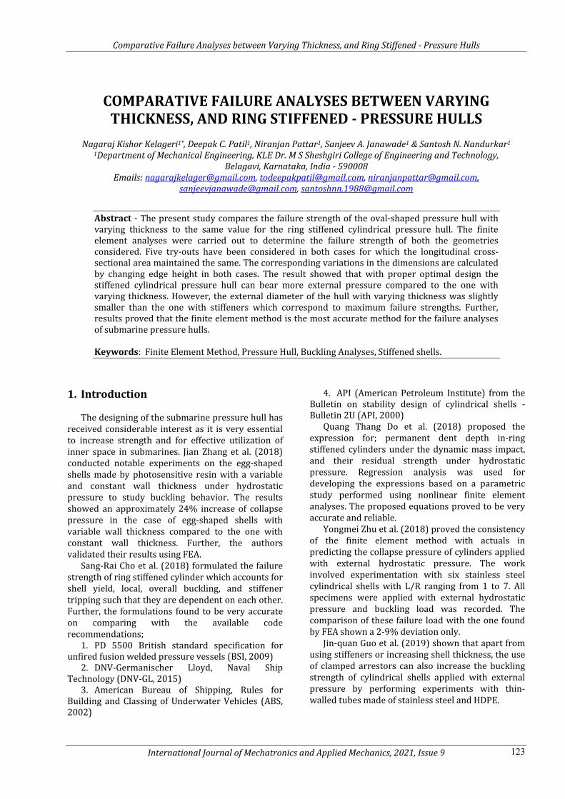
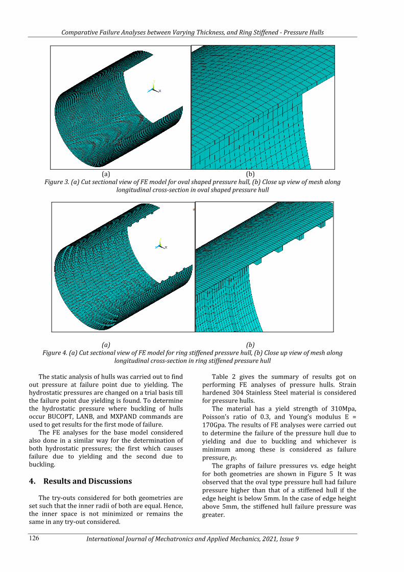
Figure 3 shows the Finite Element model of pressure hull with varying thickness. The model is made of 32800 elements. Also, the FE model of pressure hull with stiffeners is shown in Figure 4, the model consists of 11800 elements. The number of elements in both the geometries was the result of the convergence study performed for FEA. The volumes of both geometries for all try out are calculated using ETABLE, VOLU, and SSUM commands and found that all values are nearly equal as the same longitudinal cross-sectional area is maintained for each try-out considered.
Comparative Failure Analyses between Varying Thickness, and Ring Stiffened - Pressure Hulls
International Journal of Mechatronics and Applied Mechanics, 2021, Issue 9 126
(a) (b)
Figure 3. (a) Cut sectional view of FE model for oval shaped pressure hull, (b) Close up view of mesh along longitudinal cross-section in oval shaped pressure hull
(a) (b) Figure 4. (a) Cut sectional view of FE model for ring stiffened pressure hull, (b) Close up view of mesh along
longitudinal cross-section in ring stiffened pressure hull The static analysis of hulls was carried out to find
out pressure at failure point due to yielding. The hydrostatic pressures are changed on a trial basis till the failure point due yielding is found. To determine the hydrostatic pressure where buckling of hulls occur BUCOPT, LANB, and MXPAND commands are used to get results for the first mode of failure.
The FE analyses for the base model considered also done in a similar way for the determination of both hydrostatic pressures; the first which causes failure due to yielding and the second due to buckling.
4. Results and Discussions
The try-outs considered for both geometries are
set such that the inner radii of both are equal. Hence, the inner space is not minimized or remains the same in any try-out considered.
Table 2 gives the summary of results got on performing FE analyses of pressure hulls. Strain hardened 304 Stainless Steel material is considered for pressure hulls.
The material has a yield strength of 310Mpa, Poisson’s ratio of 0.3, and Young’s modulus E = 170Gpa. The results of FE analyses were carried out to determine the failure of the pressure hull due to yielding and due to buckling and whichever is minimum among these is considered as failure pressure, pf.
The graphs of failure pressures vs. edge height for both geometries are shown in Figure 5 It was observed that the oval type pressure hull had failure pressure higher than that of a stiffened hull if the edge height is below 5mm. In the case of edge height above 5mm, the stiffened hull failure pressure was greater.

Comparative Failure Analyses between Varying Thickness, and Ring Stiffened - Pressure Hulls
International Journal of Mechatronics and Applied Mechanics, 2021, Issue 9 127
Table 2. Results of Finite Element Analyses for both the geometries considered
Tr. No.
Edge Height
Pressure Hull with Varying Thickness Pressure Hull with Stiffeners
Buckling Pressure
(Mpa)
Yielding Pressure
(Mpa)
Failure Pressure
(Mpa)
Total Volume
Buckling Pressure
(Mpa)
Yielding Pressure
(Mpa)
Failure Pressure
(Mpa)
Total Volume
B1 8 1.48 2.80 1.48 4.90 1.48 2.80 1.48 4.90
1 7 1.62 2.35 1.62 4.90 2.02 2.50 2.02 4.93
2 6 1.70 2.20 1.70 4.90 3.25 2.20 2.20 4.95
3 5 1.84 1.95 1.84 4.90 4.94 1.85 1.85 4.98
4 4 1.97 1.68 1.68 4.90 6.39 1.45 1.45 5.00
5 3 2.07 1.39 1.39 4.90 3.61 1.10 1.10 5.01
COV, % 0.014 COV, % 0.792
Figure 5. Variation of failure pressure with respect to edge height for both the geometries considered
It is also evident from results obtained that; in
the case of an oval-shaped pressure hull the maximum failure pressure is for edge height of 5mm and in the case of the stiffened hull the maximum failure pressure is observed for edge height of 6mm. The maximum percentage changes in failure pressures of both geometries are; 24.32% for the oval pressure hull and 48.64% for stiffened one.
These maximum failure pressures correspond to failure due to buckling and failure due to yielding for oval pressure hull and stiffened pressure hull
respectively. Also, as it is noticed in Table 2 the changeover of failure from due to; buckling to yielding happened at 5mm edge height in the case of oval type hull whereas the same was observed at 6mm edge height in case of the stiffened pressure hull.
The comparison of the maximum outer diameter of the overall structure is also made. Table 3 shows the maximum diameter, Dmax of overall structures for both the geometries considered.
Table 3. Maximum outer diameter of structure considered for each try out in both the geometries
Try-out No. Edge Height (mm)
Maximum outer diameter, Dmax of; Oval Type Hull
(mm) Stiffened Hull
(mm) 1 7 1297 1317.11 2 6 1300 1326.22 3 5 1303 1335.33 4 4 1306 1344.44 5 3 1309 1353.56
For each 1mm reduction in thickness, the diameter of the oval type pressure hull has seen an
increase of 3mm in maximum diameter whereas in the case of stiffened pressure hull the increase is
Hull with varying thickness
Hull with Stiffeners
Comparative Failure Analyses between Varying Thickness, and Ring Stiffened - Pressure Hulls
International Journal of Mechatronics and Applied Mechanics, 2021, Issue 9 128
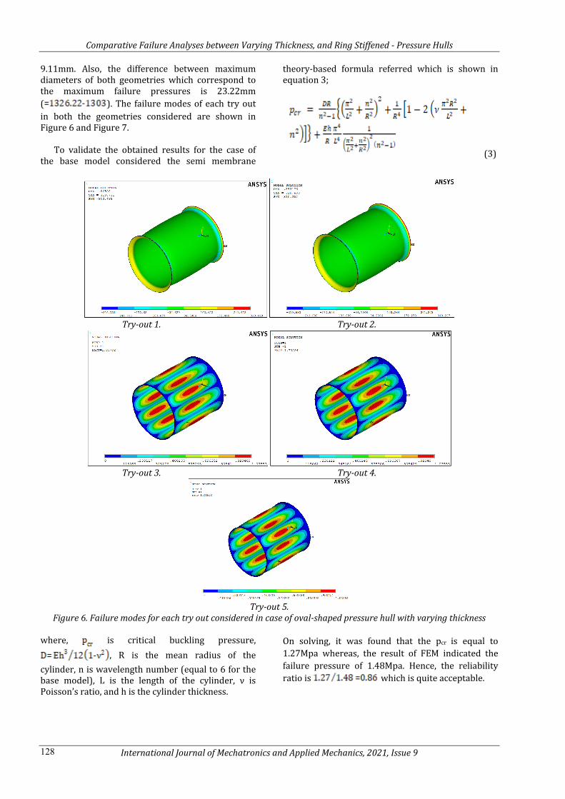
9.11mm. Also, the difference between maximum diameters of both geometries which correspond to the maximum failure pressures is 23.22mm ( ). The failure modes of each try out in both the geometries considered are shown in Figure 6 and Figure 7.
To validate the obtained results for the case of
the base model considered the semi membrane
theory-based formula referred which is shown in equation 3;
(3)
Try-out 1. Try-out 2.
Try-out 3. Try-out 4.
Try-out 5.
Figure 6. Failure modes for each try out considered in case of oval-shaped pressure hull with varying thickness where, is critical buckling pressure,
, R is the mean radius of the cylinder, n is wavelength number (equal to 6 for the base model), L is the length of the cylinder, ν is Poisson’s ratio, and h is the cylinder thickness.
On solving, it was found that the pcr is equal to 1.27Mpa whereas, the result of FEM indicated the failure pressure of 1.48Mpa. Hence, the reliability ratio is which is quite acceptable.

Comparative Failure Analyses between Varying Thickness, and Ring Stiffened - Pressure Hulls
International Journal of Mechatronics and Applied Mechanics, 2021, Issue 9 129
Try-out 1. Try-out 2.
Try-out 3. Try-out 4.
Try-out 5. Figure 7. Failure modes for each try out considered in case of oval-shaped pressure hull with varying thickness
Further, the results of the ring stiffened panel were validated using the very recent formula developed by Sang-Rai Cho et al. (2018) which proven to be very accurate and considers all possible failure types. Equation 4 states the relation between various pressures considered in ring stiffened cylindrical shell;
(4)
where, is failure pressure, is local buckling
pressure, overall buckling pressure, and is tripping pressure.
A detailed explanation of calculating all individual pressures has been provided by Sang-Rai Cho et al. (2018). With the use of these details and the fsolve() command in Scilab numerical computation software, the failure pressure was calculated for each try-out and the results are shown in Table 4. The mean reliability ratio and also the coefficient of variance indicate a good convergence between both the results.
Table 4. Comparison of FEM results with results of Equation by Sang-Rai Cho et al. (2018) Try-out No. Failure Pressure Reliability Ratio
FEM pcfem
(Mpa) Cho et al. Equation pccho
(Mpa) 1. 2.02 2.88 0.70 2. 2.20 2.47 0.89 3. 1.85 2.10 0.88 4. 1.45 1.74 0.83 5. 1.10 1.36 0.80
Mean 0.82 COV, % 8.24

Comparative Failure Analyses between Varying Thickness, and Ring Stiffened - Pressure Hulls
International Journal of Mechatronics and Applied Mechanics, 2021, Issue 9 130
5. Conclusions
The comparison of failure strength between two types of pressure hull geometries namely; the oval-shaped pressure hull with varying thickness and the one with ring stiffened cylindrical structure was made. The finite element method was used for failure analyses and its accuracy in predicting failure strength has been validated. Results showed that the ring stiffened cylindrical pressure hull can sustain 48.64% more hydrostatic pressure compared to the one with oval-shaped, varying thickness structure (can sustain 24.32%). However, a stiffened design makes the structure slightly bulkier as the maximum diameter observed for the structure which can withstand maximum external pressure is 23.22mm more than that of the oval-shaped design. It was also observed that the failure in the case of oval-shaped design happened due to local yielding for the try-out which corresponds to maximum failure strength. Whereas, for the stiffened design it corresponds to failure due to global buckling. These conclusions are very specific to the dimensions considered in the current work further analyses need to be carried out to generalize the comparison of both the geometries considered.
Conflict of Interest The authors confirm that there are no potential conflicts of interest concerning the research, authorship, and/or publication of this article.
Acknowledgments The authors are grateful to the KLE Dr. M. S. Sheshgiri College of Engineering and Technology, Belagavi, Karnataka, India for letting us use ANSYS APDL software to carry out Finite Element Analyses and institute library. Further, the authors humbly acknowledge the guidance given by Dr. K Venkateswarlu, senior principal scientist, CSIR-National Aerospace Laboratories, Bengaluru, Karnataka, India. The authors are sincerely grateful to the Scilab team for making the Scilab software an open-source tool with the use of which many equations were solved in the current work
References [1] ABS, (2002). Rules for Building and Classing
Underwater Vehicles, Systems and Hyperbaric Facilities. American Bureau of Shipping, USA.
[2] API, (2004). Bulletin 2U, 3rd Edition - Bulletin on Stability Design of Cylindrical Shells, American Petroleum Institute, USA.
[3] BSI, (2009). PD 5500: Specification for Unfired Fusion Welded Pressure Vessels, British Standard Institution, United Kingdom.
[4] DNV-GL, (2015). Rules for Classification Naval Vessel. Part 4 Sub-surface Ships Chapter 1 Submarines. DNV GL AS.
[5] Jian Zhang, Zhengdao Hua, Wenxian Tang, Fang Wang, Shuyan Wang (2018). Buckling of externally pressurised egg-shaped shells with variable and constant wall thicknesses, Thin-Walled Structures, 132, 111–119
[6] Jin-quan Guo, Deng Shuai Fan, Huan Sheng Lai, Kang Lin Liu, Zhao Guo, Chen Xu, Bing-wei He, Novel method to increase the buckling pressure of cylindrical shellsunder external pressure, Measurement, 136 (2019) 438–444
[7] Quang Thang Do, Teguh Muttaqie, Sang-Hyun Park, Hyun Kyoung Shin, Sang-Rai Cho (2018). Predicting the collision damage of steel ring-stiffened cylinders and their residual strength under hydrostatic pressure, Ocean Engineering, 169, 326–343
[8] Sang-Rai Cho, Teguh Muttaqie, Quang Thang Do, Ha Young So, Jung-Min Sohn (2018). Ultimate strength formulation considering failure mode interactions of ring-stiffened cylinders subjected to hydrostatic pressure, Ocean Engineering, 161, 242–256
[9] Yongmei Zhu, Yongjian Dai, Qingli Ma, Wenxian Tang, Buckling of externally pressurized cylindrical shell: A comparison of theoretical and experimental data, Thin-Walled Structures, 129 (2018) 309–316
[10] Eduard Ventsel, Theodor Krauthammer (2001), Thin Plates and Shells - Theory, Analysis, and Applications, Marcel Dekker, Inc., 582-585