comparative evaluation of allison t56 engine chip detectors
TRANSCRIPT

Tic FILE Copy
ARL-PROP-TM-469 AR-006-054
AD-A221 864
DEPARTMENT OF DEFENCE
DEFENCE SCIENCE AND TECHNOLOGY ORGANISATION
AERONAUTICAL RESEARCH LABORATORY
MELBOURNE, VICTORIA
Propulsion Division Technical Memorandum 469
COMPARATIVE EVALUATION OF ALLISON T56
ENGINE CHIP DETECTORS (U)
by
P.J. Gage ,)T1C
4jS ';: ECTErAY 2 11990
Approved for public release.
(C) COMMONWEALTH OF AUSTRALIA 1989
SEPTEMBER 1989
05 23. OO2

Tis AIt4FORM10HIS . j-jAOfb' AND SELL ... .I.AI _ _.
This work is copyright. Apart from any fair dealing for the purpose of study,research, criticism or review, as permitted under the Copyright Act, no partmay be reproduced by any process without written permissicn. Copyright is theresponsibility of the Director Publishing and Mdrxeting, AUPS. Inquiries shouldbe directed to the Manager, AGPS Press, Australian Government PublishingService, GPO Box 84, CANBERRA ACT 2601.
j i

AR-006-054
DEPARTMENT OF DEFENCEDEFENCE SCIENCE AND TECHNOLOGY ORGANISATION
AERONAUTICAL RESEARCH LABORATORY
Propulsion Division Technical Memorandum 469
COMPARATIVE EVALUATION OF ALLISON T56ENGINE CHIP DETECTORS
by
P.J. Gage
SUMMARY
An experimental investigation was conducted to assess the performance ofmagnetic chip detectors. Several new detectors were compared with thosecurrently in use in the Allison T56 engine.
Results indicate that the relative performance of two of the new designs wassatisfactory.
DSTOM EL B U R NE
(C) COMMONWEALTH OF AUSTRALIA 1989
POSTAL ADDRESS: Director, Aeronautical Research Laboratory,
P.O. Box 4331, Melbourne, Victoria, 3001, Australia

TABLE OF CONTENTS
1. INTRODUCTION ..................................................................................................... 1
2. EXPERIMENTAL WORK ................................................................................... 1
2.1. The Plugs
2.2. Magnetic Field Strength ..................................................................................... 1
2.3. Capture Efficiency ............................................................................................ 2
3. RESULTS OF PARTICLE CAPTURE EFFICIENCY TESTS ...................... 3
4. D ISC U SSIO N .................................................................................................................. 4
REFERENCES Accession For
IDTIC TAB
FIGURES 1-5 (0 Q'ioJusi ,, .i or
TABLES 1-12 --Av ;. ! l~' Codes
d1L;/orDist .
DISTRIBUTION LIST
DOCUM GiNT CONTROL DATA
22

}1
1. INTRODUCTION
A request was received from the RAAF for evaluation of several magnetic chipdetectors for use in the Allison T56 engine. These chip detectors are magnetic plugscapable of indicating the accretion of particles during engine operation.
The plugs to be assessed were of the quick disconnect type, and their performance was
to be compared with that of screw-in types currently in use.
Specific requirements were:
a) Comparison tests for particle capture efficiency
b) Comparison of magnetic field strengths
c) Photographs of individual magnetic plugs and captured samples.
d) Comment on the capture efficiency of the quick disconnect magneticplugs versus screw-in plugs currently in use.
2. EXPERIMENTAL WORK
2.1 The Plugs
The magnetic chip detectors currently in use in the P-3 Orion aredesignated CD34E, and those on the Hercules aircraft are designatedCD100AC and CD102AC. All of these are screw-in and indicating types.An indicating plug causes a light in the cockpit to shine when captureddebris closes an electric circuit, thus indicating that wear particles havebeen trapped. (see Fig 1).
The four new plugs to be valuated are:
TEDECO B8782TEDECO B8784TEDECO B8786TEDECO B8788 (See Fig 2)
These are quick-disconnect plugs, and all are indicating types.
Figures 1 and 2 show the different geometries of the plugs. Noteworthyvariations include collector shape and the depth on insertion into the oil.B8786 and B8788 have oil seals in their retainers, to allow removal forinspection without the oil being drained. These seals cause somerestriction to the oil flow past the detector.
2.2. Magnetic Field Strength
Test:
The magnetic field strength of the chip detectors was measured using aBell 610 gaussmeter wiih a magnetic probe. The probe was movedthrough the magnetic field of the chip detector, and the maximum fieldstrength observed was recorded.
4

2
Results:
The results of this test are listed in Table 1. Maximum values only aregiven, and they are accurate to + 0.1K gauss.
The screw-in chip detectors all had field strengths of 1.2 -1.4K auss. Thequick disconnect plugs had substantially lower field strengths. 'TEDECOB8782 was the highest of the replacements, and its strength (0.85K gauss)was only two-thirds of the value for the screw-in types.
2.3 Capture Efficiency
The Test Rig:
A brass cylindrical vessel of height 200mm and internal diameter 87mm was usedfor the test rig (Fig 3). Magnetic plugs could be located opposite each other near thelower end of the cylinder.
As it was not possible to design the rig to exactly simulate operating conditions, itwas designed to have a neutral effect on plug performance. Brass was chosen as thematerial for the cylinder because it would not effect the magnetic field of the detectors.The plugs were located so that they would be exposed to similar oil flows.
One litre of Mobiljet II synthetic lubricating oil was placed in the vessel, alongwith 0.5g of simulated wear particles. A motorised stirrer was used to ensure that theplugs were exposed to a rapidly moving, debris-laden oil stream during the tests.
Wear Particles
The particles used in the tests were prepared from mild steel filings. The filingswere sieved to produce the following size distribution, similar to that used in previoustests (Ref 1).
SIZE (gim) % (by weight)
<53 4053-74 20
75-104 20105-147 20
0.5g of the filings were used in 1 litre of oil, giving a concentration of 560 ppm (byweight).
Test Procedure:
A direct comparison of the capture efficiency of any two plugs was achieved byplacing them in a particle rich environment, so that both were exposed to the sameparticle concentration. The detector which collected the greater mass of debris wasdefined as more efficient, by a factor equal to the ratio of the captured particle masses.For these test, CD102AC was chosen as an arbitrary standard. All plugs were testeddirectly against CD102AC, thus allowing indirect comparison of any two plugs.
Initially all plugs were weighed to determine their mass without deposit.
0.5g of simulated wear particles were placed at the bottom of the test cylinder.j Two plugs were inserted, and the oil added.
--------------------------------
.1i

3
The stirrer was then switched on for one minute. This time limit was chosen afterit had been shown that all plugs continued to collect debris for more than two minutes.This was shown by weighing the plugs after each thirty seconds of stirring. The mass ofall plugs continued to increase after two minutes of operation, indicating that debris wasstill being collected at that time.
At the completion of the test run, the oil was drained and the plugs removed.The plugs, with the deposit still attached, were carefully washed in n-hexane to removethe oil, and then allowed to dry for 15 minutes. They were then weighed a second time,to determine the mass of collected particles.
After each test the particle concentration was restored by adding debris of massequal to the amount just collected.
Repeatability of results was checked by placing two CD102AC chip detectors inthe cylinder, and testing them three times. To determine the influence of samplingposition on plug capture efficiency, the position of the plugs was reversed, and a furtherthree tests completed. The results, shown in Table 2, indicate that relative captureefficiency was consistent, with plug 1 (S/NQMO11) consistently 0.9 times as effective asplug 2 (S/N QL23).
The results in Table 3 show that position of the plugs did not significantly altertheir effectiveness, as the captured mass was the same (within 1%) for individual plugsin different locations.
Two series of comparative tests were conducted:
In the first series, all plugs were mounted so that their magnets lay flush with thecylinder wall, so that flow near each plug was known to be similar.
In the second series, the quick disconnect plugs were tested in their retainers.Figure 2 shows that detectors B8784 and B8788 have been designed so that themagnetic heads are mounted some distance from the wall. The different depth ofinsertion was expected to alter the flow conditions because the flow velocity and particleconcentration may vary at different distances from the wall. B8786 and B8788 wereexpected to experience flow restrictions due to the presence of an oil seal, which partlyshrouded the collecting surface (See Fig 2).
3. RESULTS OF PARTICLE CAPTURE EFFICIENCY TESTS
The results of the first series of tests, are listed in Tables 4 - 9. Three tests werecompleted with all plugs, each plug being compared with CD102AC. The averagevalues of the three tests are included in each table, along with an indication of theexperimental scatter about the mean.
Tables 10 - 13 show the results for the new plugs tested in their own retainers.Again three tests were completed with all plugs.
The capture efficiency of each plug, expressed relative to the efficiency ofCD102AC, is presented in Figure 4.
Photographs of captured sample debris on all plugs are presented in Figure 5.
C,4

4
4. DISCUSSION
Under the conditions of this series of tests, the quick release chip detector B8782had an efficiency about 1.5 times that of the screw-in types (CD34E, CD100AC,CD102AC), both when it was flush mounted and when mounted in its retainer.
The quick release plug B8784 matched the efficiency of CD102AC when it wasmounted in its retainer. It was less effective when flush mounted.
Plugs B8786 and B8788 are not as effective as the screw-in types.
It appears that the following factors effect capture efficiency:
i) magnetic field strength - the plugs with greater field strength tend to bemore effective.
ii) magnet geometry - the broad flat capture surface of B8782 was veryefficient.
iii) depth of insertion into the reservoir - B8784 performed markedly betterwhen mounted in its retainer (capture surface 22 mm from the wall).
iv) presence of an oil seal - B8786 performance worsened when it wasmounted in its retainer, with the oil seal shrouding its magnet.Performance of B8788 was little changed, but this may be because theimprovement due to increased depth of insertion was cancelled by thedegradation due to presence of an oil seal.
According to these test, the plugs may be ranked in the following order(best performance to worst performance)
B8782CD346
CD100ACCD102AC, B8784B8786, B8788
B8782 is a suitable replacement for the screw-in plugs.
B8784 may be used to replace CD102AC.
B8786 and B8788 have lower performance than detectors currently in use.
REFERENCES
1. ATKINS, M.L.Evaluation of Allison T56 Engine Ma.netic Plug Efficiency. Letter Report.Aeronautical Research Laboratory, File C2/03.
I.N

CD 34ESCREW IN
FLUSH MOUNTINGNO OIL SEAL
MAGNETIC FIELD 1.2K GAUS,"
CD 100ACSCREW IN
FLUSH MOUNTINGNO OIL SEAL
MAGNETIC FIELD 1.4K GAUSS
CD 102AC
SCRCW INFLUSH MOUNTING
NO OIL SEALMAGNETIC FIELD 1.3K GAUSS
FIGURE 1

B8782QUICK RELEASE
FLUSH MOUNTINGNO OIL SEAL
-l MAGNETIC FIELD 0.85K GAUSS
B8784QUICK RELEASE
nEPTH OF INSERTION: 22mmNO OIL SEAL
MAGNETIC FIELD 0.2K GAUSS
FIGURE 2
- -.--, ~-.- -.-

B8786QUICK RELEASE
FLUSH MOUNTINGOIL SEAL
MAGNETIC FIELD 0.25K GAUSS
B8788QUICK RELEASE
DEPTH OF INSERTION: 17mmOIL SEAL
MAGNETIC FIELD 0.3K GAUSS
FIGURE 2 CONTINUED

Stirrer
A B-
Magnetic chipdetector
FIGURE 3 TEST RIG FOR COMPARING CHIP DETECTORS

2.0 -
1.8 VO
1.6
1.4
lelative,article 1.2
captureefficiency 1.0 -- -. ....
(CD 102AC=1) 770.8
0.6
0.4
0.2 ,II-
C0102AC Co0ooAC C034E 80782 B8784 88786 88788
Chip detectorFIGURE 4(a) ALL DETECTORS FLUSH MOUNTED
2.0
1.8
1.6
1.4
Relative 1.2particlecapture -- -
efficiency 1.0 -- - - -.
0.8
0.6
0.4
0.2 . 8 2.
C0102AC 88782 Bd;94 88786 88788
Chip detectorFIGURE 4(b) QUICK DISCONNECT DETECTORS MOUNTED IN THEIR RETAINERS
4

CD 34E
CD T P AC
I FIGURES5 TYPICAL PARTICLE CAPTURES

B8782
B8784
FIGURE 5 CONTINUED

B8786
B8788
FIGURE 5 CONTINUED
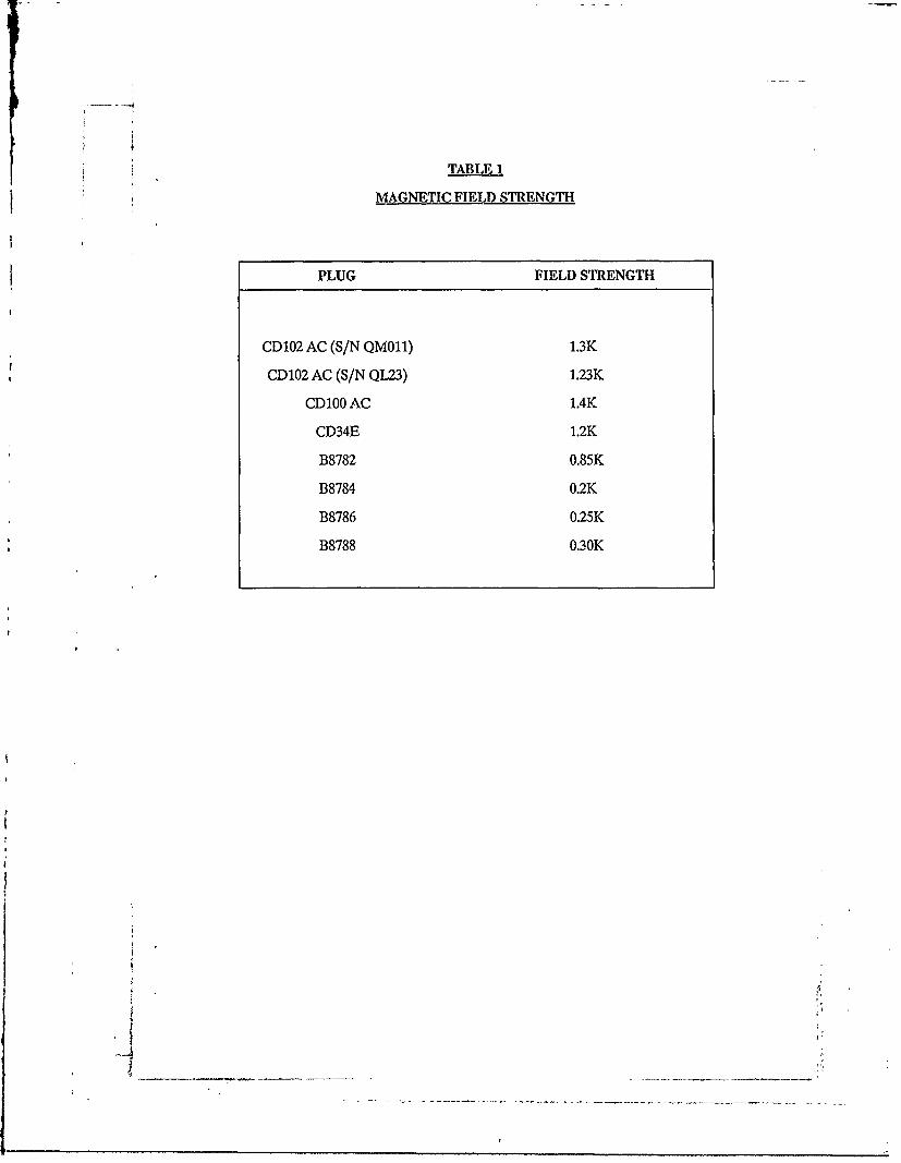
TABLE I
MAGNETIC FIELD STRENGTH
PLUG FIELD STRE NGTH
CD 102 AC (S/N QMO11) 1.3K
CD102 AC (S/N QL23) 1.23K
CD100 AC 1.4K
CD34E 1.2K
B8782 0.85K
B8784 0.2K
B8786 0.25K
B8788 0.30K

TABLE 2
Plug 1 CD102AC Plug 2 CD203AC Relative EfficiencySIN QM011 S/N QL23 Mass OM011
Mass QL23Capture Mass (g) Capture Mass (g)
0.1147 0.1277 0.900.1286 0.1418 0.910.1172 0.1350 0.870.1251 0.1382 0.910.1153 0.1320 0.870.110.1311 0.89
0.1196 + 7.5% 0.1343 . 5% 0.90
Plug 1 is consistently 0.9 times as effective as Plug 2
TABLE 3
a) Plug 1CD102AC (S/N QM011)
Capture Mass (g) Capture Mass (g)Position A Position B
0.1147 0.12510.1286 0.1153
0.1172 0.1164
Av = 0.1202 + 7% Av = 0.1189 + 5%
Relative efficiency Position A = 2 = 1.01Position B 0.1189
b) Plug 2CD102AC (S/N QL23)
Capture Mass (g) Capture Mass (g)
Position A Position B
0.1277 0,13820.1418 0.13200.13500.1311
0.1348 + 5% 0.1338 + 3.3%
Relative Efficiency Position A = 0.1348 1.01Position B 0.1338
~~1 _
- - -.-------- .---------.

RELATIVE EFFICIENCIES (ALL PLUGS FLUSH MOUNTED)
TABLE 4
CD100AC vs CD102AC (S/N QL23)
Capture Mass (g) Capture Mass (g) Relative EfficiencyCD100AC CD102AC Mass 100AC
Mass 102AC
0.1398 0.1231 1.140.1414 0.1310 1.080.1407 0 1.01
0.1406. +1% 0.1276+3% 1.10
TABLE 5
CD34E vs CD102AC (S/N QL23)
Capture Mass (g) Capture Mass (g) Relative EfficiencyCD34E CD102AC Mass CD34E
Mass 102AC
0.1569 0.1260 1.250.1668 0.1438 1.160.1616 .1336 1.21
0.1617 + 3% 0.1345 + 7% 1.21
TABLE 6
B8782 vs CD102AC (S/N QL23)
Capture Mass (g) Capture Mass (g) Relative EfficiencyB8782 CD102AC Mass B8782
Mass 102AC
0.1803 0.1101 1.640.2093 0.1154 1.810,2060 015 1.78
0.1985L +9% 0.1138 + 3% 1.74
J
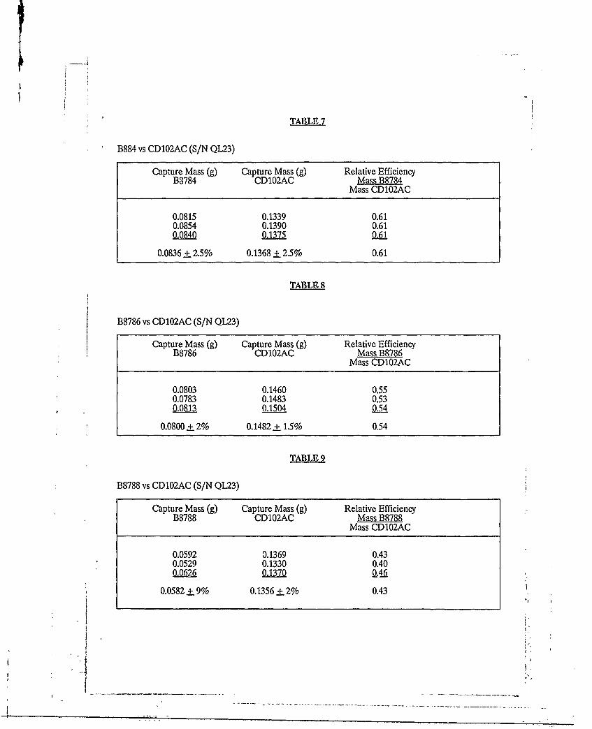
TABLE 7
B884 vs CD102AC (S/N QL23)
Capture Mass (g) Capture Mass (g) Relative EfficiencyB8784 CD102AC Mass B8784
Mass CD102AC
0.0815 0.1339 0.610.0854 0.1390 0.61
S0.137 0.61
0.0836 + 2.5% 0.1368 + 2.5% 0.61
TABLE8
B8786 vs CD102AC (S/N QL23)
Capture Mass (g) Capture Mass (g) Relative EfficiencyB8786 CD102AC Mass B8786
Mass CD102AC
0.0803 0.1460 0.550.0783 0.1483 0.5308 0.1504 0.54
0.0800 + 2% 0.1482 ± 1.5% 0.54
TABLE 9
B8788 vs CD102AC (S/N QL23)
Capture Mass (g) Capture Mass (g) Relative EfficiencyB8788 CD102AC Mass B8788
Mass CD102AC
0.0592 0.1369 0.430.0529 0.1330 0.40
0.0582 + 9% 0.1356 + 2% 0.43

0 ' 00
-4 -' m4 tnt-.,
p +1 00 o +
6y acu3
e-O +1 CC~I+
00 C~00
Inn054 0004)
SOA- 00%
00____ ______________ ______ __________4q=P Q=C

000
66C561 c, 66
-4 r-400 C'
00 \00066 1v C\\06614 R0 0 D- )c 0\.
cl~ cn
~C 0 c 0 j

DISTRIBUTION
AUSTRALIA
Department of Defence
Defence CentralChief Defence ScientistAS, Science Corporate Management (shared copy)FAS, Science Policy (shared copy)Director, Departmental PublicationsCounsellor, Defence Science, London (Doc Data Sheet Only)Counsellor, Defence Science, Washington (Doc Data Sheet Only)OIC TRS, Defence Central LibraryDocument Exchange Centre, DISB (18 copies)Librarian H Block, Victoria Barracks, Melbourne
Aeronautical Research LaboratoryDirectorLibraryChief -Flight Mechanics and Propulsion DivisionHead - Propulsion BranchBranch File - PropulsionAuthor: P.J. Gage
Materials Research LaboratoryDirector/Library
Defence Science & Technology Organisation - SalisburyLibrary
Navy OfficeNavy Scientific Adviser (3 copies Doc Data sheet)Aircraft Maintenance and Flight Trials Unit
Army OfficeScientific Adviser - Army (Doc data sheet only)
Air Force OfficeAir Fcrce Scientific AdviserAircraft Research and Development Unit
Scientific Flight GroupLibrary
Engineering Branch LibraryDirector General Engineering - Air ForceDirector General Air Warfare Plans and PolicyAHQ (SMAINTSO)HQ Logistics Command (SLENGO)
HQADFDirector General Force Development (Air)
SPARES (10 COPIES)TOTAL (50 COPIES)
-- - ---- - --
AL 149 DEPARTMIENT OF DEFENCE PAGOCSlfCATIONAUCLASIIEDI1F
DOCUMENT CONTROL DATA UNCLASSIEDPlUlVACY MARKING
IA. ARNUMBER lb. LXrABLSIIMENI'NUMBR 2. DOCUMENTIDATI 3.TASKNUMBER
AR-006-054 ARL-PROP-TM-469 SEPTEMBER 1989 AIR 89/563
4. TITLE 5. SE URIYCLASSIFICATION 6, NO. PAGES
COMPARATIVE EVALUATION OF (PLACCAPPRoPRIAT CLASSIICATIONALLISON T56 ENGINE CHIP IN BOX(S) I1. SECRUT(S), CONF. (C) 20DETECTORS RETICTM (R).UNCIASSIFI (U)).
DOCUMENT Tnu ABSIlACr
& AUTIIOR(S) 9.DOWNGRADING/DWEImNG INSTRUCTIONS
PJ. GAGENot applicable
lo. CORPORATEAUTHOR AND AD DRESS 1. oPFCe/POStoCN RISPONSIBLE FOIL-
AERONAUTICAL RESEARCH LABORATORY SPONSOR RAAF
P.O. BOX 4331, MELBOURNE VIC 3001 SECURITY
DOWNGRADING N/A
APPROVAL CFPD
12. SECONDARYDI.-TRIBUION(OF11IISDOCUMENI~
Approved for public release
OVERSEAS 12NQUIRIES OUTSIDE STATED LIMITATIONS SI IOULD BE REFERRED TIIROUGII ASIDS. DEFENCE INFORMATION SERVI,.ES BfIAN .A.
DEPARUiENTOF DEFENCE CAM PBELL PARIrACr 2601
13a. Tis DOCUMENT MAY BE ANNOUNCED IN CATALOGUES AND AWARENESS SERVICES AVAILABLE TO....
No limitations
13b. CITATION.")R °71 IE PURPOSES (lB. CASUALANNOUNCEMENI) MAY BE L UNRESTRICTED OR F AS FOR 134.
14, DESCRI'ORS 15. DRDA SUBJECTMagnetic detectors CATEGORIES
Ga5 turbine enginesAllison T56 engines 0081D
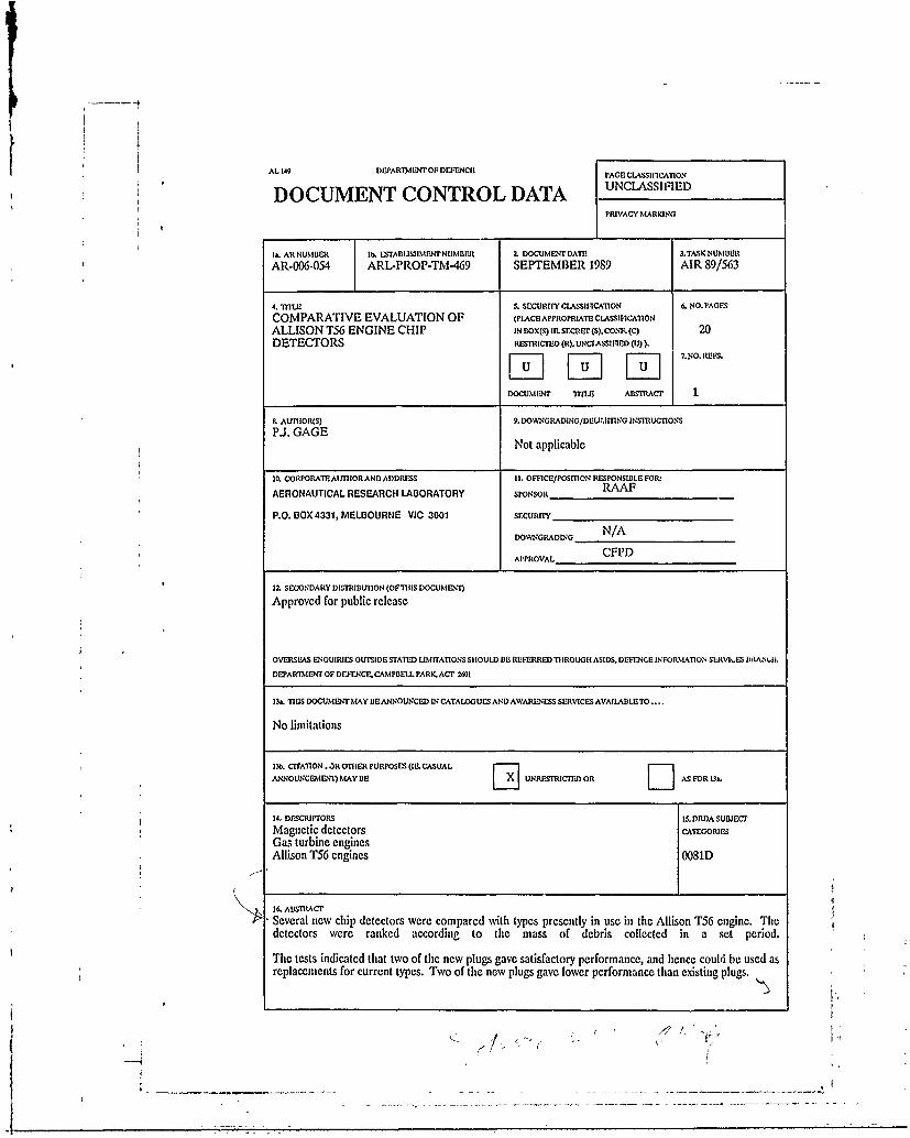
I. ABSIRACT
Several new chip detectors were compared with types presently in use in the Allison T56 engine. Thedetectors were ranked according to the mass of debris collected in a set period.
The tests indicated that two of the new plugs gave satisfactory performance, and hence could be used asreplacements for current types. Two of the new plugs gave lower performance than existing plugs.
Y7 H
.1"

PAGICLASSIFnCATION
UNCLASSIFIED
PRIVACY MARKING
Tis PAO IS TO Oil USEDTO RCORD INIFORMATION WIIICII IS RID&UIR)ED IY le IETAIUSIIMENT IOR ITS OWN USE BUT W1iC WILL tNOr liE
ADDED T O1 11 DISIs DATA UNLESS SP ..... FICALLY REQUMET
I& ABSTRACT (CON).
17. IMPRIN'
AERONAUTICAL RESEARCH LABORATORY, MELBOURNE
18. DOCUMDUSERI SAND NUMBER 19, COSTCODE 20. TYPI'RrOPOITAND PEI:OD COVRED
PROPULSION 453561TECHNICAL MEMORANDUM 469
21. COMPUTER PROGRAMS USED
2Z ESTABUSIIMENT FILM R 4(S)
C2/03
23. ADDITIONAL INFORMATION (AS REOUIRED)