comparative analysis of rectangular microstrip patch array antenna...
TRANSCRIPT
Comparative Analysis of Rectangular Microstrip Patch
Array Antenna with Different Feeding Techniques
K. Srinivasa Naik1, S. Aruna2, Karri.Y.K.G.R.Srinivasu1
and Darimisetti Sai Kiran1
1Department of Electronics and Communication Engineering1
Vignan’s Institute of Information and Technology, Visakhapatnam, A.P, India
[email protected] 2Department of Electronics and Communication Engineering2,
2Andhra University, Visakhapatnam, A.P, India
Abstract. Wireless communication system plays a prominent role in many
applications like long distance communication, mobile applications, high
performance aircraft, missile applications. For this purpose wireless
communication systems requires antenna with compact, flexible, ease of
installation, high gain and directivity. Rectangular single element microstrip
patch antenna used in many applications, but these are not suitable for satellite
communications, space crafts, high resolution Radars because they need
enhanced gain and also directivity. In view of the above facts to enhance the
gain and directivity and low beam width by increasing the number of patch
elements with series, parallel and individual feed network at an operating
frequency of 10GHz with dielectric constant 2.2. The 4 element and 8 element
design has carried out in this work by comparing with single element. Some of
the system operational characteristics depend on directional properties of
antenna. HFSS software is a tool for this project design and implementation.
Antenna primary parameters such as impedance band width, directivity, gain,
radiation pattern, beam width were compared among all three types of feed
network.
Keywords: Wireless communication; Rectangular micro strip patch antenna;
Beam width; Gain; Directivity; Operating frequency; HFSS (High Frequency
Structure Simulator).
1 Introduction
A simple conducting element which provides impedance matching between source to
load can act as an antenna. The morphological changes applied to conducting
elements can turn into an antenna and it must also satisfy both maximum power
transfer theorem and reciprocity theorem is well. Though the antennas are extensively
used in communications they must be capable of radiating the energy to longer
distance. Hence a flared structure is incorporated to the antenna [1-2].
To find the distance of the ships and to navigate at sea shore, the ships are
subjected to roll and pitch in marine radar applications. The sum patterns which are
Advanced Science and Technology Letters Vol.147 (SMART DSC-2017), pp.135-141
http://dx.doi.org/10.14257/astl.2017.147.21
ISSN: 2287-1233 ASTL Copyright © 2017 SERSC

observed in the ships are very useful in wireless communication and in high
resolution radar applications [3-5].
2 Microstrip Patch Antenna
Microstrip patch antennas have advantages like low size, high performance, low cost,
low profile antenna. With the increase in the advancement of science and technology
the usage of microstrip patch antenna has been increased because of their low
structural characteristics [6].
For accurate and high efficiency system design requires a lossless substrate
material and substrate height. Here in this pursuit ROGERS RT-DUROID 58880 is a
lossless substrate material with dielectric constant value of 2.2 [7]. Generally, we
have different types of micro strip patch antennas like rectangular, circular, square,
triangular, disk sector and many more but out of this rectangular micro strip patch
antenna having essential characteristics, low cost, ease to design. The general design
of microstrip patch antenna shown in figure 1.
Fig. 1. Rectangular Microstrip Patch Antenna
To provide better efficiency and larger bandwidth. Microstrip patch antennas
constitutes of a narrow conducting strip whose thickness is very negotiable when
compared to its operating wavelength (t<<λ0), the height of the patch is usually
dependent on the material (h << λ0, usually 0.003λ0 ≤ h ≤ 0.05λ0) which is separated
by a fraction of λ0 above the conducting plane. The length L of the element is usually
λ0/3 < L < λ0/2 for a rectangular patch [8].
Advanced Science and Technology Letters Vol.147 (SMART DSC-2017)
136 Copyright © 2017 SERSC

3 Design Equations
(1)
r
W
(2)
21
1212
1
2
1
W
hrrreff
(3)
12
2 r reff o o
L Lf
(4)
4 Design of the Models
The dimensions of the single element patch antenna are follows, Length of the patch
0.9cm, width of the patch 1.19cm, inset feed length 0.295cm, feed width of 0.243cm
are calculated by using above mentioned transmission line model equations. The same
units of the single element microstrip patch antenna are also used in designing four
element microstrip patch antenna with series feed. The separation gap between two
patches is λ/2. The feeding port always exists at the extreme end patch out of 4
elements. All the 4 elements are interconnected with a narrow feed line [9]. The 8
element design of patch array antenna network is also utilizing the dimensions of the
one element antenna. Upon the substrate all the 8 elements were placed serially and
the feeding is provided to the last element in the array.
The space consumption of the 8 element array is more when compared to the 4
element and single element antenna. All the patch elements are separated by a gap of
λ/2 and the lumped port excitation has been given using 50ohm feed line. The Four
element and Eight element rectangular microstrip patch Antenna are excited with
Series Feed, Parallel Feed and Individual Feed Networks.
Fig. 2. Single Element Rectangular Microstrip Patch Antenna
002
1
reff
rL
f
Advanced Science and Technology Letters Vol.147 (SMART DSC-2017)
Copyright © 2017 SERSC 137

Fig. 3. Four Element Rectangular
Microstrip Patch Array Antenna with
Series Feed
Fig. 4. Four Element Rectangular Microstrip Patch
Array Antenna with Parallel Feed
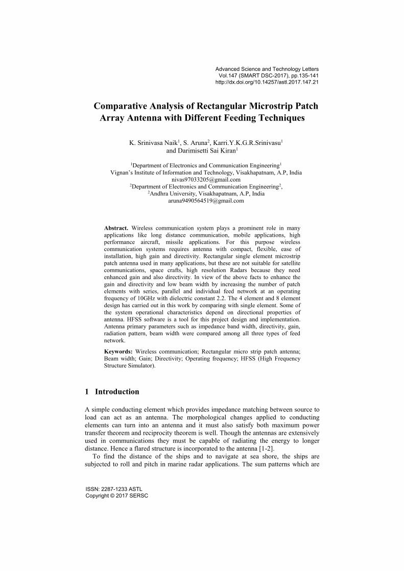
5 Results
The following section gives result analysis of all the above mentioned designs are
shown below with their plots.
Advanced Science and Technology Letters Vol.147 (SMART DSC-2017)
138 Copyright © 2017 SERSC

Advanced Science and Technology Letters Vol.147 (SMART DSC-2017)
Copyright © 2017 SERSC 139
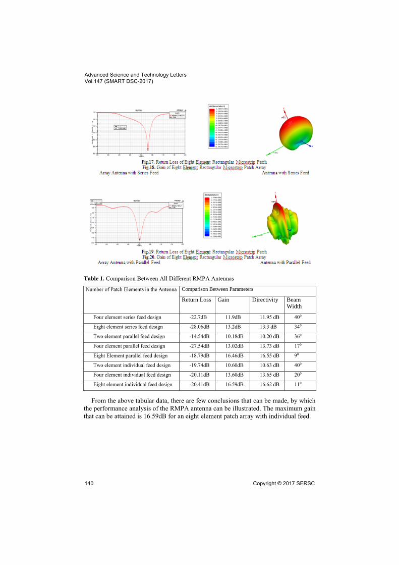
Table 1. Comparison Between All Different RMPA Antennas
Number of Patch Elements in the Antenna Comparison Between Parameters
Return Loss Gain Directivity Beam Width
Four element series feed design -22.7dB 11.9dB 11.95 dB 400
Eight element series feed design -28.06dB 13.2dB 13.3 dB 340
Two element parallel feed design -14.54dB 10.18dB 10.20 dB 360
Four element parallel feed design -27.54dB 13.02dB 13.73 dB 170
Eight Element parallel feed design -18.79dB 16.46dB 16.55 dB 90
Two element individual feed design -19.74dB 10.60dB 10.63 dB 400
Four element individual feed design -20.11dB 13.60dB 13.65 dB 200
Eight element individual feed design -20.41dB 16.59dB 16.62 dB 110
From the above tabular data, there are few conclusions that can be made, by which
the performance analysis of the RMPA antenna can be illustrated. The maximum gain
that can be attained is 16.59dB for an eight element patch array with individual feed.
Advanced Science and Technology Letters Vol.147 (SMART DSC-2017)
140 Copyright © 2017 SERSC

6 Conclusion
The designed array antennas are centered at frequency around 10GHz can be adopted
into Radar applications because of its low beam width. Return loss value increases
when the antenna feeds in a serial way, and coming to parallel feed mechanism, there
is a fluctuation of return loss value due to the number of elements. Whereas in
individual feed, the variation in the return loss also increases but it is negotiable.
Irrespective of whether an antenna is in series, parallel or individual feed, if the
number of patch elements increases, the Gain and Directivity value increases whereas
beam width decreases. Hence it can be concluded that when compared to all three
types of feeding methods, individual feed technique offers better results in terms of
Gain and Directivity.
References
1. Kraus, John D. "Antennas." (1988).
2. Raju, G. S. N. Antennas and wave propagation. Pearson Education India, 2006.
3. Pozar, David M. "Microstrip antenna aperture-coupled to a microstripline." Electronics
letters 21 (1985): 49.
4. Naik, K. Srinivasa, and S. Aruna. "Investigations on the generation of patterns for marine
radar applications." Indian Journal of Science and Technology 9, no. 7 (2016).
5. Naik, K. Srinivasa, and G. S. N. Raju. "Studies on Difference patterns from Cosecant
patterns." IOSR-JECE 9, no. 6 (2014): 37-44.
6. Balanis, Constantine A. Antenna theory: analysis and design. John Wiley & Sons, 2016.
7. Skolnik, Merrill Ivan. "Radar handbook." (1970).
8. Marrocco, Gaetano. "The art of UHF RFID antenna design: impedance-matching and size-
reduction techniques." IEEE antennas and propagation magazine 50, no. 1 (2008): 66-79.
9. Ab Wahab, Norfishah, Zulkifli Bin Maslan, Wan Norsyafizan W. Muhamad, and Norhayati
Hamzah. "Microstrip rectangular 4x1 patch array antenna at 2.5 GHz for WiMax
application." In Computational Intelligence, Communication Systems and Networks
(CICSyN), 2010 Second International Conference on, pp. 164-168. IEEE, 2010.
10. Garg, Ramesh. Microstrip antenna design handbook. Artech house, 2001.
11. Carver, Keith, and James Mink. "Microstrip antenna technology." IEEE transactions on
antennas and propagation 29, no. 1 (1981): 2-24.
12. Mak, C. L., K. M. Luk, K. F. Lee, and Y. L. Chow. "Experimental study of a microstrip
patch antenna with an L-shaped probe." IEEE Transactions on Antennas and
Propagation 48, no. 5 (2000): 777-783.
13. Kumar, Girish, and K. P. Ray. Broadband microstrip antennas. Artech House, 2003.
Advanced Science and Technology Letters Vol.147 (SMART DSC-2017)
Copyright © 2017 SERSC 141