compact-range coordinate system established using...
TRANSCRIPT

SANDIA REPORT SAND2006-7541 Unlimited Release Printed December 2006
Compact-Range Coordinate System Established Using a Laser Tracker Edwin A. Bryce and Floyd H. Gallegos Prepared by Sandia National Laboratories Albuquerque, New Mexico 87185 and Livermore, California 94550 Sandia is a multiprogram laboratory operated by Sandia Corporation, a Lockheed Martin Company, for the United States Department of Energy’s National Nuclear Security Administration under Contract DE-AC04-94AL85000. Approved for public release; further dissemination unlimited.
Issued by Sandia National Laboratories, operated for the United States Department of Energy by Sandia Corporation.

NOTICE: This report was prepared as an account of work sponsored by an agency of the United States Government. Neither the United States Government, nor any agency thereof, nor any of their employees, nor any of their contractors, subcontractors, or their employees, make any warranty, express or implied, or assume any legal liability or responsibility for the accuracy, completeness, or usefulness of any information, apparatus, product, or process disclosed, or represent that its use would not infringe privately owned rights. Reference herein to any specific commercial product, process, or service by trade name, trademark, manufacturer, or otherwise, does not necessarily constitute or imply its endorsement, recommendation, or favoring by the United States Government, any agency thereof, or any of their contractors or subcontractors. The views and opinions expressed herein do not necessarily state or reflect those of the United States Government, any agency thereof, or any of their contractors. Printed in the United States of America. This report has been reproduced directly from the best available copy. Available to DOE and DOE contractors from U.S. Department of Energy Office of Scientific and Technical Information P.O. Box 62 Oak Ridge, TN 37831 Telephone: (865) 576-8401 Facsimile: (865) 576-5728 E-Mail: [email protected] Online ordering: http://www.osti.gov/bridge Available to the public from U.S. Department of Commerce National Technical Information Service 5285 Port Royal Rd. Springfield, VA 22161 Telephone: (800) 553-6847 Facsimile: (703) 605-6900 E-Mail: [email protected] Online order: http://www.ntis.gov/help/ordermethods.asp?loc=7-40#online
2

Sand 2006-7541
Unlimited Release Printed December 2006
Compact–Range Coordinate System Established Using a Laser Tracker
Edwin A. Bryce
Manufacture Processes & Services Department
Floyd H. Gallegos Materials Value Stream Department
Sandia National Laboratories P.O. Box 5800
Albuquerque, NM 87185-0958
ABSTRACT Establishing a Cartesian coordinate reference system for an existing Compact Antenna Range using the parabolic reflector is presented. A SMX (Spatial Metrix Corporation) M/N 4000 laser–based coordinate measuring system established absolute coordinates for the facility. Electric field characteristics with positional movement correction are evaluated. Feed Horn relocation for alignment with the reflector axis is also described. Reference points are established for follow-on non-laser alignments utilizing a theodolite.
3

4

Introduction Electric field characterization of the quiet zone in a microwave compact range is a difficult and time-consuming task. The recent availability of laser tracking measuring devices (see Figures 1 / A-B) presents a method for establishing a permanent absolute Cartesian coordinate reference system for a compact antenna range. The laser tracking system has a high degree of accuracy, 0.001 inches in a 9 foot volume. The laser tracking accuracy allows for correction of positioner mechanical movement. The electrical field phase data is adjusted for variations in mechanical movement of the field probe. The modified electrical field data can now be evaluated to a new level of precision. The flatness of the electric field in the quiet zone (6foot diameter) of the compact range is now known to be 10.6° in the horizontal and 17.8° in the vertical at 16.7 GHz.
Figures 1/A-B. SMX M/N 4000 Laser Tracker.
The Compact Range is located on Kirtland Air Force Base in Albuquerque, NM. The building was designed exclusively for Radar Cross Section (RCS) and Antenna Pattern Measurements. The chamber is a separate building within a building for isolating the environmental effects of temperature and vibration. The internal room or Anechoic Chamber is 110 feet long by 42 feet wide and 26 feet high. The walls and ceiling are covered with 8 inch pyramidal and wedge anechoic absorber. There are two compact-range parabolic reflectors in the chamber separated by an anechoic divider. One reflector is in the north end of the chamber, and the other in the southeast corner. The north end reflector is a modified Scientific Atlanta MN 5752 reflector. This reflector has a 12 foot diameter, 12 foot focal length half-parabola dish with a rolled edge
5

for control of electric field diffraction. The overall dimension is 31 feet and 4 inches wide by 21 feet and 10 inches high. The quiet zone or flat electric-field area is 6 feet in diameter and 8 feet long (see Figure 2). The approach or technique is to measure the parabolic dish and establish a Cartesian coordinate reference system defined by the intersection of two perpendicular planes referenced to the dish. The first plane is normal to the parabola axis and intersects the vertex of the parabola. The parabola axis and a line perpendicular to the gravitational force direction define the other plane. The vertex is defined as the origin (zero point) for the X, Y & Z axis. The focal axis is defined as the Z-axis with –Z directed away from the dish. The X-axis is defined by a line level to earth which passes through the vertex. -X is right hand facing the dish. The Y-axis is vertical to earth and passes through the vertex. +Y is above the vertex. After the coordinate system is established, field probe measurements are made of the electric field. Establishing Facility Coordinates
Flow Chart
Establish Rough or
“Fit” Coordinate
System
Measure Parabola Section
Measure Reference
Points
Establish Coordinate Reference
System
Measure Reference
Level Point for Clocking Orientation
Because of the physical size of the parabolic section to be measured, it was necessary to first establish reference or “relocation points” in the room. In order to maintain the integrity of the coordinates measured, the relocation points must be at fixed locations. The relocation points serve two functions: (1) allow movement of the laser tracker in the event that a feature could not be measured from the tracker’s current location. The coordinate system is re-established by measuring the relocation points from the new location; and (2) allow the establishment of a remote “home” or reset point for the tracker. In some instances it was not feasible to use the standard home location mounted on the tracker.
6

Vertex
Relocation Point 1
Relocation Point 2 Relocation Point 3
Figure 2. Compact Range Parabolic Reflector.
The tracker software requires a minimum of three relocation points for tracker movement. A total of five were used for this project. Three of the relocation points were set on the front of the paraboloid and two were set on the large doorjambs of the room. Relocation points 1, 2, and 3 were approximately 175 inches apart in the horizontal plane (X-axis). Relocation points 1 and3 were approximately 47 inches from relocation point 2 in the horizontal plane (Z-axis). The relocation points were set using manufacturer supplied “flat nests” that allow the measuring device SMR (Spherical Mounted Reflector) to be magnetically held in place with a high degree of location repeatability. The “flat nests” have a recessed center hole allowing them to be physically mounted with either a nut and bolt or self tapping screws.
7
Tracker Output
SMR Position
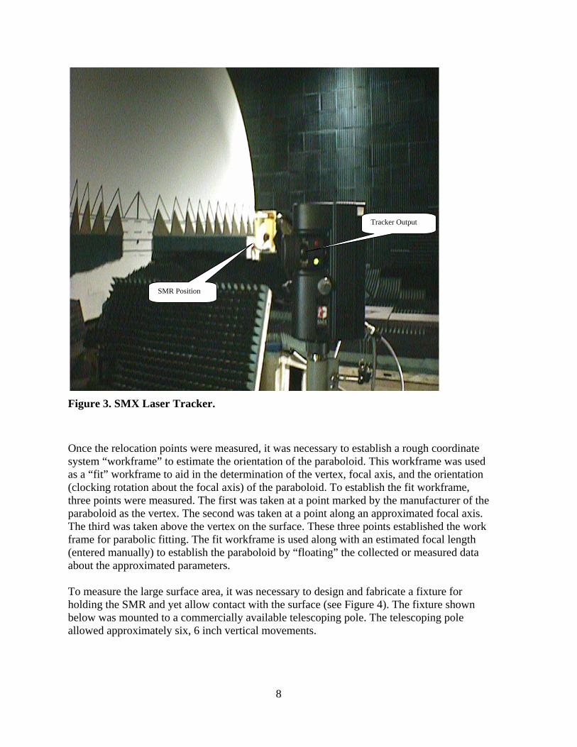
Figure 3. SMX Laser Tracker.
Once the relocation points were measured, it was necessary to establish a rough coordinate system “workframe” to estimate the orientation of the paraboloid. This workframe was used as a “fit” workframe to aid in the determination of the vertex, focal axis, and the orientation (clocking rotation about the focal axis) of the paraboloid. To establish the fit workframe, three points were measured. The first was taken at a point marked by the manufacturer of the paraboloid as the vertex. The second was taken at a point along an approximated focal axis. The third was taken above the vertex on the surface. These three points established the work frame for parabolic fitting. The fit workframe is used along with an estimated focal length (entered manually) to establish the paraboloid by “floating” the collected or measured data about the approximated parameters. To measure the large surface area, it was necessary to design and fabricate a fixture for holding the SMR and yet allow contact with the surface (see Figure 4). The fixture shown below was mounted to a commercially available telescoping pole. The telescoping pole allowed approximately six, 6 inch vertical movements.
8

Mount for telescoping pole
SMR
Figure 4. Mounting Fixture for Telescoping Pole.
SMR
Figure 5. Probing Parabolic Reflector Surface.
9
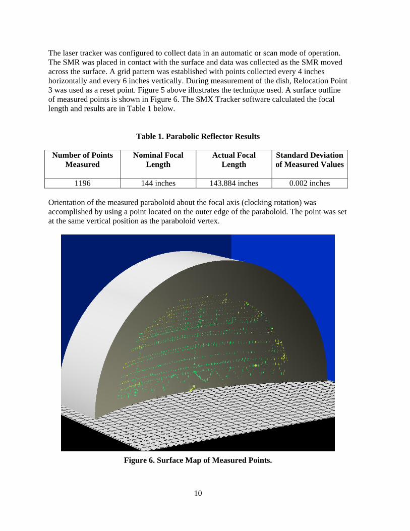
The laser tracker was configured to collect data in an automatic or scan mode of operation. The SMR was placed in contact with the surface and data was collected as the SMR moved across the surface. A grid pattern was established with points collected every 4 inches horizontally and every 6 inches vertically. During measurement of the dish, Relocation Point 3 was used as a reset point. Figure 5 above illustrates the technique used. A surface outline of measured points is shown in Figure 6. The SMX Tracker software calculated the focal length and results are in Table 1 below.
Table 1. Parabolic Reflector Results Number of Points
Measured Nominal Focal
Length Actual Focal
Length Standard Deviation of Measured Values
1196 144 inches 143.884 inches 0.002 inches Orientation of the measured paraboloid about the focal axis (clocking rotation) was accomplished by using a point located on the outer edge of the paraboloid. The point was set at the same vertical position as the paraboloid vertex.
Figure 6. Surface Map of Measured Points.
10

The laser tracker used is not equipped with an integrated level, and to establish this point required an additional measuring device. A laser level system, an AGL Beam Machine, shown in Figure 7 below was set up. When the unit is level to earth, it emits a visible beam. The beam can be traced in a complete 360° circle about the unit. First, a software command was given to aim the tracker beam at the vertex of the measured paraboloid. The laser level beam was set to the height of the tracker vertex beam by overlapping the two beam spots. The spot sizes are approximately 0.200 in diameter. Once set, the laser level beam was rotated to a position to the outer edge of the paraboloid. The beam position was marked and the tracker was then used to measure the point location. This point is approximately 160 inches from the vertex on the outer edge of the dish near Relocation Point 1. This point was then used to complete the establishment of the coordinate system. The parabola vertex and the outer point now form a line which is level to earth. The axis of the parabola was then measured to determine how level the axis was to the Earth. The laser level was set up on a tripod and raised until the laser pointed to the vertex on the reflector. A SMR nest was mounted on a linear slide and then mounted to another tripod. The tripod was positioned at the far end of the room away from the dish. Using the tracker software and the linear slide, the SMR was positioned to the X origin of the coordinate system. The laser level was now rotated to the SMR position. Using the tripod’s vertical adjustment, the SMR was positioned to the center of the laser level beam. Once both the horizontal (X origin) and vertical adjustments (laser level position) were set, the position of the SMR was measured using the tracker software. The deviation in the Y-axis over the distance from the vertex defined the tilt of the focal axis (rise over run). The results are in Table 2 below.
Table 2. Paraboloid Focal Axis Tilt Z Coordinate Distance
From Vertex Y Coordinate Vertical
Displacement Angular Tilt of Focal
Axis
481.316 inches 0.088 inches 0.0105 degrees
11
Adjustment of levels
Beam Output
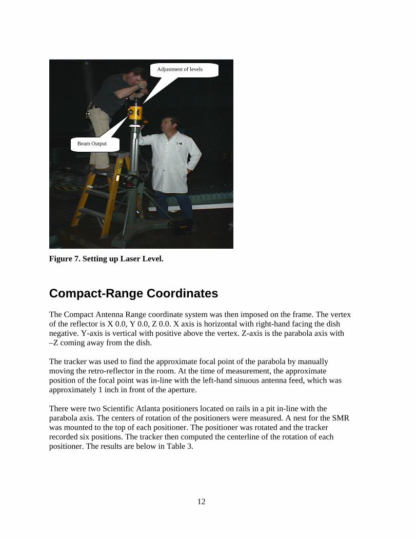
Figure 7. Setting up Laser Level.
Compact-Range Coordinates The Compact Antenna Range coordinate system was then imposed on the frame. The vertex of the reflector is X 0.0, Y 0.0, Z 0.0. X axis is horizontal with right-hand facing the dish negative. Y-axis is vertical with positive above the vertex. Z-axis is the parabola axis with –Z coming away from the dish. The tracker was used to find the approximate focal point of the parabola by manually moving the retro-reflector in the room. At the time of measurement, the approximate position of the focal point was in-line with the left-hand sinuous antenna feed, which was approximately 1 inch in front of the aperture. There were two Scientific Atlanta positioners located on rails in a pit in-line with the parabola axis. The centers of rotation of the positioners were measured. A nest for the SMR was mounted to the top of each positioner. The positioner was rotated and the tracker recorded six positions. The tracker then computed the centerline of the rotation of each positioner. The results are below in Table 3.
12

Table 3. Positioner Locations
Positioner Z Coordinate X Coordinate
5 ton -357.216 inches 3.435 inches
15 ton -475.458 inches 2.707 inches
Reference Points The use of a theodolite may be required for future projects at the range. Allowing for the reference of tracker measurements to a theodolite, reference points were established using brass plugs that were drilled in the floor and epoxied in place (see Figure 8). The retro-reflector nests were positioned over the plugs and a transfer punch marked the plug. The first brass reference plug was positioned in front of the dish in line with the axis of the dish. The second and third reference plugs were located equal-distance from the dish axis and approximately even with the end of the quiet zone. A fourth was located on the left in front of the reflector. Locations are defined in Table 4.
Brass Plug
Figure 8. Brass Plug Reference Point.
13
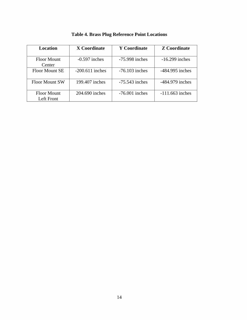
Table 4. Brass Plug Reference Point Locations
Location X Coordinate Y Coordinate Z Coordinate
Floor Mount Center
-0.597 inches -75.998 inches -16.299 inches
Floor Mount SE -200.611 inches -76.103 inches -484.995 inches
Floor Mount SW 199.407 inches -75.543 inches -484.979 inches
Floor Mount Left Front
204.690 inches -76.001 inches -111.663 inches
14

Distribution 2 MS 0899 Technical Library 4536 2 MS 9018 Central Technical Files 8944 10 MS 0958 Edwin Bryce 02433
15