compact outdoor bs30 bts maintenance manual3
TRANSCRIPT

ZXG10-BS30 Compact Outdoor BTSMaintenance Manual
(Troubleshooting)
Version1.5
ZTE CORPORATION ZTE Plaza, Keji Road South, Hi-Tech Industrial Park, Nanshan District, Shenzhen, P. R. China 518057 Tel: (86) 755 26771900 800-9830-9830 Fax: (86) 755 26772236 URL: http://support.zte.com.cn E-mail: [email protected]

LEGAL INFORMATION Copyright © 2006 ZTE CORPORATION. The contents of this document are protected by copyright laws and international treaties. Any reproduction or distribution of this document or any portion of this document, in any form by any means, without the prior written consent of ZTE CORPORATION is prohibited. Additionally, the contents of this document are protected by contractual confidentiality obligations. All company, brand and product names are trade or service marks, or registered trade or service marks, of ZTE CORPORATION or of their respective owners. This document is provided “as is”, and all express, implied, or statutory warranties, representations or conditions are disclaimed, including without limitation any implied warranty of merchantability, fitness for a particular purpose, title or non-infringement. ZTE CORPORATION and its licensors shall not be liable for damages resulting from the use of or reliance on the information contained herein. ZTE CORPORATION or its licensors may have current or pending intellectual property rights or applications covering the subject matter of this document. Except as expressly provided in any written license between ZTE CORPORATION and its licensee, the user of this document shall not acquire any license to the subject matter herein. The contents of this document and all policies of ZTE CORPORATION, including without limitation policies related to support or training are subject to change without notice.
Revision History
Date Revision No. Serial No. Purpose
10- Aug-06 R1.0 sjzl20061266 English – For Customers
ZTE CORPORATION Values Your Comments & Suggestions! Your opinion is of great value and will help us improve the quality of our product documentation and offer better services to our customers.
Please fax to: (86) 755-26772236; or mail to Documentation R&D Department, ZTE CORPORATION, ZTE Plaza, A Wing, Keji Road South, Hi-Tech Industrial Park, Shenzhen, P. R. China 518057.
Thank you for your cooperation!
Document Name ZXG10–BS30 (V1.5) Compact Outdoor BTS Maintenance Manual (Troubleshooting)
Product Version V1.5 Document Revision Number R1.0
Equipment Installation Date
Presentation: (Introductions, Procedures, Illustrations, Completeness, Level of Detail, Organization, Appearance)
Good Fair Average Poor Bad N/A
Accessibility: (Contents, Index, Headings, Numbering, Glossary)
Good Fair Average Poor Bad N/A
Your evaluation of this documentation
Intelligibility: (Language, Vocabulary, Readability & Clarity, Technical Accuracy, Content)
Good Fair Average Poor Bad N/A
Your suggestions for improvement of this documentation
Please check the suggestions which you feel can improve this documentation: Improve the overview/introduction Make it more concise/brief
Improve the Contents Add more step-by-step procedures/tutorials
Improve the organization Add more troubleshooting information
Include more figures Make it less technical
Add more examples Add more/better quick reference aids
Add more detail Improve the index
Other suggestions
__________________________________________________________________________
__________________________________________________________________________
__________________________________________________________________________
__________________________________________________________________________
__________________________________________________________________________
# Please feel free to write any comments on an attached sheet.
If you wish to be contacted regarding your comments, please complete the following:
Name Company
Postcode Address
Telephone E-mail

This page is intentionally blank.

Contents
About this Manual............................................................. i
Purpose................................................................................ i Intended Audience ................................................................. i Prerequisite Skill and Knowledge .............................................. i What is in this Manual ............................................................ i Related Documentation.......................................................... ii Conventions......................................................................... ii How to Get in Touch............................................................. iii
Chapter 1..........................................................................1
Safety Instruction............................................................1
Overview .......................................................................1
Safety Symbols...............................................................1 Toxicant ..............................................................................3 Electrical Safety....................................................................4 Antistatic .............................................................................5 Battery................................................................................6 Electromagnetic Radiation ......................................................7 Working High above the Ground..............................................7 Fans ...................................................................................8 High Temperature .................................................................8 Plugging/Unplugging a Module ................................................9 Do Not’s ..............................................................................9
Chapter 2........................................................................11
Common Faults ..............................................................11
Common Faults............................................................. 11 Troubleshooting in BTS Commissioning Stage ......................... 12 Troubleshooting at BTS Maintenance Stage............................. 16 Troubleshooting at BTS Cutover and Expansion Stage .............. 30
Chapter 3........................................................................37

Notification Messages....................................................37
Summary of Notifications ............................................... 37 Notification for No Traffic in BS Cell........................................37
Chapter 4........................................................................39
Alarm messages.............................................................39
Alarms Description ........................................................ 39
Alarm Handling............................................................. 40 CMM Alarm.........................................................................40 ETRM Alarm......................................................................49 DPM Alarm .........................................................................71 Backbone Node Alarm..........................................................74
Appendix A.....................................................................79
Replacement of Modules and Boards............................79
Appendix B .....................................................................93
Common Maintenance Tables........................................93
Appendix C .....................................................................97
Abbreviations.................................................................97
Figures..........................................................................101
Tables ...........................................................................103
Index............................................................................105

Confidential and Proprietary Information of ZTE CORPORATION i
About this Manual
Purpose
This Manual provides procedures and guidelines that support the Troubleshooting of the ZXG 10- BS 30 Compact Outdoor BTS.
Intended Audience
This document is intended for engineers and technicians who perform troubleshooting activities on the ZXG 10-BS 30 Compact Outdoor BTS.
Prerequisite Skill and Knowledge
To use this document effectively, users should have a general understanding of wireless telecommunications technology. Familiarity with the following is helpful:
ZXG10-BS 30 Compact Outdoor BTS and its various components.
ZXG10-BS 30 Compact Outdoor BTS Hardware Installation.
What is in this Manual
This Manual contains the following chapters:
T AB L E 1 - C H AP T E R S U M M AR Y
Chapter Summary
Chapter 1, Safety Instructions
It explains the safety symbols and safety measures to observe during troubleshooting.
Chapter 2, Troubleshooting
This chapter describes common faults in BTS during commissioning, cutover expansion, and maintenance stages along with troubleshooting carried out.
Chapter 3, Notification This chapter describes about notification

ZXG10-BS30 (V1.5) Compact Outdoor BTS Maintenance Manual (Troubleshooting)
ii Confidential and Proprietary Information of ZTE CORPORATION
Chapter Summary
Messages messages related to BTS including their description, cause and handling.
Chapter 4, Alarm Messages
This chapter describes comprehensive and systematic description of all the alarms, including alarm information, alarm cause, handling method, and precautions in the handling.
Appendix A Replacement of modules and boards is common part of routine maintenance and troubleshooting. It is recommended to call ZTE technical staff for technical support and guidelines.
Appendix B This section describes types of maintenance carried by maintenance professional along with their record tables.
Related Documentation
The following documentation is related to this manual:
ZXG10-BS30 (V1.5) Compact Outdoor BTS Guide to Documentation
ZXG10-BS30 (V1.5) Compact Outdoor BTS Maintenance Manual (Emergency Handling)
ZXG10-BS30 (V1.5) Compact Outdoor BTS Maintenance Manual (Routine Maintenance)
ZXG10-BS30 (V1.5) Compact Outdoor BTS Technical Manual
ZXG10-BS30 (V1.5) Compact Outdoor BTS Hardware Manual
ZXG10-BS30 (V1.5) Compact Outdoor BTS Installation Manual
Conventions
ZTE documents employ the following typographical conventions.
T AB L E 2 - TY P O G R AP H I C AL C O N V E N T I O N S
Typeface Meaning
Italics References to other Manuals and documents.
“Quotes” Links on screens.
Bold Menus, menu options, function names, input fields, radio button names, check boxes, drop-down lists, dialog box names, window names.
Typographical Conventions

About this manual
Confidential and Proprietary Information of ZTE CORPORATION iii
Typeface Meaning
CAPS Keys on the keyboard and buttons on screens and company name.
Constant width Text that you type, program code, files and directory names, and function names.
[ ] Optional parameters.
{ } Mandatory parameters.
| Select one of the parameters that are delimited by it.
Note: Provides additional information about a certain topic.
Checkpoint: Indicates that a particular step needs to be checked before proceeding further.
Tip: Indicates a suggestion or hint to make things easier or more productive for the reader.
T AB L E 3 - M O U S E OP E R AT I O N C O N V E N T I O N S
Typeface Meaning
Click Refers to clicking the primary mouse button (usually the left mouse button) once.
Double-click Refers to quickly clicking the primary mouse button (usually the left mouse button) twice.
Right-click Refers to clicking the secondary mouse button (usually the right mouse button) once.
Drag Refers to pressing and holding a mouse button and moving the mouse.
How to Get in Touch
The following sections provide information on how to obtain support for the documentation and the software.
If you have problems, questions, comments, or suggestions regarding your product, contact us by e-mail at [email protected]. You can also call our customer support center at (86) 755 26771900 and (86) 800-9830-9830.
ZTE welcomes your comments and suggestions on the quality and usefulness of this document. For further questions, comments, or suggestions on the documentation, you can contact us by e-mail at [email protected]; or you can fax your comments and suggestions to (86) 755 26772236. You can also browse our website at http://support.zte.com.cn, which contains various interesting subjects like documentation, knowledge base, forum and service request.
Mouse Operation
Conventions
Customer Support
Documentation Support
ZXG10-BS30 (V1.5) Compact Outdoor BTS Maintenance Manual (Troubleshooting)
iv Confidential and Proprietary Information of ZTE CORPORATION
This page is intentionally blank.

Confidential and Proprietary Information of ZTE CORPORATION 1
C h a p t e r 1
Safety Instruction
This chapter explains the safety symbols and safety measures to observe during routine maintenance.
Overview It is important to read safety instructions before operation and maintenance of ZXG10-BS30 equipment. These instructions are supplementary to any local safety regulations in place. In case of any conflict, local safety regulations shall prevail.
Maintenance personnel should have preliminary knowledge about safety operations and must have received training on ZTE equipment maintenance and operations.
Observe related equipment precautions and special safety instructions during maintenance, provided by ZTE.
Some important safety instructions are discussed in the chapter. ZTE shall not bear any liabilities incurred by violation of universal safety operation requirements, or violation of safety standards for designing, manufacturing and equipment usage.
Safety Symbols Table 4 .lists general safety symbols used in the manual.

ZXG10-BS30 (V1.5) Compact Outdoor BTS Maintenance Manual (Troubleshooting)
2 Confidential and Proprietary Information of ZTE CORPORATION
T AB L E 4 – GE N E R AL S AF E T Y S Y M B O L S
Safety symbol Meaning
No smoking: Smoking is prohibited
No Flammables: No flammable materials can be stored.
No touching: Do not touch.
Universal alarm: General safety precaution.
Erosion: Beware of erosion.
Electric shock: There is a risk of electric shock.
Electrostatic: Device may be sensitive to static electricity.
High temperature: Surface is hot and may cause personal injury if touched.
Microwave: Beware of strong electromagnetic field.
Laser: Beware of strong laser beam.
Universal alarm symbols comprises of four levels: Danger, warning, caution and note in descending of criticality.
Danger: Indicates an imminently hazardous situation, which, if not avoided, could result in death or serious injury. Limit its use to only extreme situations.
Warning: Indicates a hazardous situation, which, if not avoided, could result in serious injuries, equipment damages or interruption of major services.

Chapter 1-Safety Instruction
Confidential and Proprietary Information of ZTE CORPORATION 3
Caution: Indicates a potentially hazardous situation, which, if not avoided, could result in moderate injuries, equipment damages or partial service interruption.
Note: Indicates helpful information that if ignored, could result in minor injuries, equipment damages or partial service interruption.
Every safety symbol has a text description of its safety level and a detailed description of its contents.
Toxicant
Warning: Beryllia is a toxic chemical commonly used in transistors and base stations components, such as power amplifier circuit and hybrid combiner circuit. Do not make direct contact with these components.
Broken, ruptured or squashed beryllia components produce beryllia powder, which is extremely harmful to human skin and mucous membrane.
Beryllia components are dangerous only when they are broken, so they need a lot of care while installing and disposing.
While disposing beryllia components, comply with local regulations of chemical or special waste disposal.
In case of any accident or any physical contact involving beryllia, rinse the wound with water and rush to a hospital for proper treatment.
Personnel exposed to such components must have complete knowledge about precautionary measures to avoid any hazards.
Warning: Some components in base station contain chemicals like hydrochloride. These components release toxic gas when burnt.
Do not burn components to prevent toxic gas release after combustion. Dispose off according to the local regulations of chemical or special waste disposal.
Beryllia
Hydrochloride

ZXG10-BS30 (V1.5) Compact Outdoor BTS Maintenance Manual (Troubleshooting)
4 Confidential and Proprietary Information of ZTE CORPORATION
Electrical Safety
Warning: In high DC and AC voltage operation, use special purpose tools.
Danger: Direct or indirect contact with high DC or AC voltage through any moist object may result in serious injury.
AC equipment installation must comply with the local safety regulations.
Personnel responsible for AC equipment installation must have proper qualification in high DC and AC power.
Do not wear a watch, chain, bracelet, ring or any other conductive objects while working with high voltages.
Prevent moisture from entering the equipment while working in a moist environment.
Note: Never install or uninstall power cables while they are live because when touched with a conductor may produce sparks, resulting in fire or damage to eyes.
Shut down the power supply before installing or uninstalling a power cable.
Connect cables according to the labels and instructions given in installation and hardware manuals.
Warning: Drilling in the cabinet without prior permission is prohibited.
Unnecessary drilling can damage cables inside the cabinet. The metal pieces blown due to drilling can cause short circuits in the circuit board.
While drilling in the cabinet, wear gloves and move aside cables in the cabinet. Protect eyes from metal pieces blowing while drilling.
Clean the cabinet after drilling.
Tools
High Voltage
Power Cables
Drilling

Chapter 1-Safety Instruction
Confidential and Proprietary Information of ZTE CORPORATION 5
Danger: Do not perform high voltage and tower operations in thunderstorm.
Thunderstorm produces a strong electromagnetic field in the atmosphere, so avoid all tower and high voltage operations.
Take lightening protection measures by grounding the equipment to prevent any damage.
Antistatic
Note: Static electricity produced by human body can damage sensitive components on the circuit board, such as large integrated circuits (ICs).
Friction caused by human body is the root cause of electrostatic charge accumulation. In dry weather, the static charge carried by human body can be up to 30kV and can remain in human body for a long time. Person carrying static charge can damage a component by touching and hence transferring the charge to the component.
To prevent human static charge from damaging sensitive components, wear antistatic wrist strap and ground its other end before touching the equipment or holding a plug board, circuit board, IC chip etc.
To prevent accidental electric shock, serially connect the connection cable between the wrist and grounding point with a resistor above 1 MΩ. A resistor above 1 MΩ is enough to discharge static voltage.
Check antistatic wrist strap regularly and never use a cable other than the original cable that comes along with the wrist strap.
Static-sensitive module or board should not touch the objects that can carry static electricity. For example, friction caused by package bags, transfer box and transfer belt made from insulation plastic, may cause electrostatic shock to the components because they can transfer static charge from human body or floor.
Keep the static-sensitive module or board in anti-static bag during storage and transportation.
Ground the test device to discharge the static charge before use.
Do not place the module or board near strong magnetic field, such as cathode-ray tube of the monitor. Keep it at least 10 cm away.
Lightning

ZXG10-BS30 (V1.5) Compact Outdoor BTS Maintenance Manual (Troubleshooting)
6 Confidential and Proprietary Information of ZTE CORPORATION
Battery
Danger: A short-circuited battery can be harmful to human body. Although common batteries have low voltage, but instant powerful current caused by short circuit can release a great amount of energy.
Prevent metal objects to short circuit the battery, for example, short circuit caused by mishandling the operation tools. If possible, cut the battery supply before any operation.
Danger: Do not use any unsealed lead-acid battery, because the gases released by the battery may erode the equipment or cause fire. Fix the battery and place it horizontally.
Select a ventilated place for the battery having proper fire protection measures because a battery can release combustible gases. To prevent high temperature due to sunshine, equip the battery room with sun-screening curtains.
Danger: Very high temperature of the battery may cause deformation, damage or acid liquid overflow.
If the battery temperature exceeds 60ºC, check acid liquid overflow in the battery.
If acid liquid has overflowed, dispose off according to the local regulations of chemical or special waste disposal.
Danger: If acid liquid overflows, absorb and neutralize it as soon as possible.
Take special care of the acid liquids while moving a soaked battery. If acid liquid overflows, use NaHCO3, Na2CO3 or Na2CO3.10H2O to neutralize and absorb it.
Substances used for absorption and neutralization of acid liquids must conform to battery manufacturers’ instructions.
Danger: Do not replace the standard model battery with any other model battery because it might explode.
Short Circuit
Harmful Gases
High Temperature
Acid Liquids
Battery Replacement
Chapter 1-Safety Instruction
Confidential and Proprietary Information of ZTE CORPORATION 7
Electromagnetic Radiation
An antenna of a device generates electromagnetic radiations. The safety requirement might not be sufficient at a place too near to the antenna. Personnel with proper training and relevant qualifications must install and maintain the equipment. Equipment radiation design shall comply with IEEE C95.1-1991.
Warning: Operating on high intensity RF equipment can seriously affect human body.
During installation and maintenance of the antenna on a tower mounted with several antennas from different operators, there must be mutual agreement to shutdown the transmission.
Warning: During installation and servicing operations around the operating antenna, keep adequate distance from the antenna.
Do not unplug the transmitter output feeder connector or the antenna feeder cable connector while the transmitter is operating.
Shut down the transmitter before unplugging the feeder cable connector or working beside the transmitter antenna.
Working High above the Ground
Warning: While working high above the ground, prevent objects from falling down.
Working at heights should conform to local national service regulation requirements, such as:
All personnel working at heights must undergo proper training.
Prevent operation machinery and tools from falling down.
Wear helmet and safety belt as a safety precaution.
Wear cold-protection clothes in cold areas.
Check all hoisting equipment before starting to work at height.
Warning: Do not stay or walk under the hoisted weight.
Hoisting Weights

ZXG10-BS30 (V1.5) Compact Outdoor BTS Maintenance Manual (Troubleshooting)
8 Confidential and Proprietary Information of ZTE CORPORATION
To move, replace or dismantle heavy equipment, make sure that appropriate facilities are available.
Personnel to perform hoisting tasks must have proper training.
Check hoisting tools and make sure they are firmly fixed on support frame or walls.
Check the ladder if it is in good condition for use. Do not overweight the ladder.
Before climbing on a ladder, make sure that someone is holding it. Adopt proper safety measures when there is a tilt over 5 m, 3 m for an upright ladder or when used in dangerous operation environment. Expand A-type ladder, completely.
Ideally, a ladder tilt is of 75 degrees. Bottom ends of the ladder should not be slippery. Place the ladder firmly on a flat area. Do not place it over the objects that can slide or move, such as cartons and stones.
Always face the ladder while climbing it. Keep the center of gravity within the ladder edges. Hold the ladder with one hand and make sure to place both feet on the ladder. Do not climb beyond last four steps. Ladder used to climb onto a roof should be at least 1 m above the eave.
Fans
Warning: Keep fingers or body away from the running fan blades. Do not use any tool on the fan before it is powered off and fan blades stop.
When replacing parts, put screws, tools and parts in a safe place. If they fall into the running fan, they can damage the fan or other devices.
While working with devices near the fan, keep fingers or devices away from the fan to avoid human injury or damage to devices.
High Temperature
Warning: Surface temperature of some components is very high. Do not touch it.
Using Ladders
Chapter 1-Safety Instruction
Confidential and Proprietary Information of ZTE CORPORATION 9
Plugging/Unplugging a Module
Note: Do not plug a board with force as it might bend the pins at the backplane. Insert the board along the slot.
While holding a board in hand, keep hands off the board circuits, components, connectors and wiring.
Do Not’s
Note: Do not conduct internal maintenance or equipment debugging without prior permission.
Replacing parts or changing equipment may incur extra danger, therefore, do not replace parts or change the equipment without prior permission.
To ensure safety, please contact ZTE in case of any problem.
10 Confidential and Proprietary Information of ZTE CORPORATION
This Page is intentionally blank.

Confidential and Proprietary Information of ZTE CORPORATION 11
C h a p t e r 2
Common Faults
This chapter describes common fault occurring in BTS during maintenance, commissioning, and cutover and expansion stages. This chapter also explains fault symptoms, fault analysis and troubleshooting method.
Common Faults Common faults in BS30 BTS are categorized in the following manner:
1. Faults occurred during Base Transceiver Station (BTS) commissioning.
2. Faults occurred during BTS maintenance.
3. Faults occurred during cutover and expansion.
BTS is in normal working condition but MS can not access the network.
Major Standing Wave Ratio (SWR) alarm.
Poor call conversation quality.
BTS coverage decreases.
Cell carrier not occupied.
Link Access procedure on D channel (LAPD) link break.
BTS working normally but handover with adjacent cell is not possible.
Unstable MS signal in idle state.
Unstable MS signal in busy state.
Traffic Channel (TCH) assignment success ratio is low.
Echoes in call conversation.
Commissioning Stage
Maintenance Stage
ZXG10-BS30 (V1.5) Compact Outdoor BTS Maintenance Manual (Troubleshooting)
12 Confidential and Proprietary Information of ZTE CORPORATION
Transmission faults alarms.
LNA Alarm.
Antenna Feeder Faults
Unidirectional call conversation.
Stand alone Dedicated Control Channel (SDCCH) is occupied for long time.
High call drop ratio in the cell.
Troubleshooting in BTS Commissioning Stage
BTS is In Normal State but MS Can Not Access Network
The MS has no network access but BTS is in normal working condition.
OMCR parameter settings, antenna feeder system and Extended Trans Receiver Module (ETRM).
Trace Abis interface message to check whether there is channel request messages. If there is no channel request message the fault might be on network side.
Fault occurring on network side might be due to following factors:
Location Area Code (LAC) and Cell Identity (CI) on MSS side are not consistent with BSS.
Radio parameters are not configured properly.
Antenna system faults.
Transmission Faults:
Network synchronization failure observed from CLK LED indicator on Control and Maintenance Module (CMM).
Abis synchronization failure observed from SYN LED indicator on CMM board.
Even if there is no alarm in transmission; such as High Level Data Link Control (HDLC). There might be fault in transmission system consider an example given below.
Example: BSC can receive signal from BTS but BTS can not receive signal from BSC. OMCR will indicate
Cutover and Expansion.
Symptoms
Related Parts
Analysis and Location

Chapter 2-Common Faults
Confidential and Proprietary Information of ZTE CORPORATION 13
transmission is normal even if there is fault in transmission by judging from the fact that BSC is receiving signal.
Trouble shooting process is as follows:
Check whether LAC and CI code consistent on MSS and BSS side; if not configure them correctly.
Adjust radio parameters such as RACH busy threshold and Random Access Error Threshold to less than their present value.
Decrease MS minimum receiving signal level.
Set Cell Bar to Yes and check if the fault still exists, go to next step.
Check CMM board CLK LED Indicator; if it is Red replace the CMM board.
T AB L E 5 - CMM B O AR D C L K LED I N D I C AT O R S T AT U S
CLK LED Indicators Description
Green Network Synchronization
Green Blinking Clock Phase Lock
Red Clock Failure
Check whether the frequency error on CMM board is within specified limits; if not calibrate it.
Check whether transmission grounding is good enough and check whether there is transmission alarm on following boards:
i. Trunk Interface Circuit (TIC) board E1 LED indicator.
ii. CMM boards STA LED indicators.
T AB L E 6 – T IC B O AR D E1 LED I N D I C AT O R S T AT U S
E1 LED Indicator Description
Green blinks quickly Indicates Normal Running
Green Indicates Alarm
Green Off E1 Port Is Not Initialized
T AB L E 7 – CMM B O AR D STA LED I N D I C AT O R S T AT U S
STA LED Indicators Description
Red blinks slowly LAPD link broken
Red blinks quickly HDLC link broken
Check ETRM board for normal working conditions if ETRM is faulty replace Transceiver Station Module for Edge (TSME).
Troubleshooting
ZXG10-BS30 (V1.5) Compact Outdoor BTS Maintenance Manual (Troubleshooting)
14 Confidential and Proprietary Information of ZTE CORPORATION
If problem still persists call ZTE’s local maintenance offices support.
Handling Major SWR Alarm
A major SWR alarm occurs in OMCR.
Duplexer Module (DPM), TSME, and antenna feeder system.
SWR of the antenna feeder system is too high (crossing 3.0 threshold).
If the SWR alarm is reported to CMM by Transceiver processing unit (TPU) might be due to Disconnection of antenna cable with backplane.
Open circuit occurred at DPM external port.
Troubleshooting is carried out as follows:
In case of low traffic in the cell remotely reset the ETRM and check whether alarm disappears.
If alarm persists remotely reset CMM through OMCR and check whether alarm disappears.
Check whether TSME is in good contact with backplane; if not plug TSME properly.
Check the antenna feeder connectors for any loose contacts; if necessary change connectors.
Check whether internal jumper connectors are in proper conditions; if damaged change internal jumper connectors.
Measure Voltage Standing Wave Ratio (VSWR) with Site Master and check whether it is in the permissible limits.
Poor Call Conversation Quality
Poor call conversation quality with distinct noises.
OMCR radio parameters, RF cable, antenna feeder system, CMM board.
Poor voice quality can be caused by high bit error rate in wireless interface, clock faults, and co-channel interference effect.
Poor call quality can be caused by wrong configuration of DIP switch port S3~S9 port for matching E1 of the receiving end
Symptoms
Related Parts
Analysis and Location
Troubleshooting
Symptoms
Related Parts
Analysis and Location
Chapter 2-Common Faults
Confidential and Proprietary Information of ZTE CORPORATION 15
(75 ohm co –axial cable to 120 ohm twisted pair cable and vice versa).
For more information on DIP switch setting please refer ZXG 10- BS 30 compact BTS Hardware Installation Manual.
Low receiving signal level might be caused by following factors:
i. Improper parameters configuration
MS initial access signal level (MsTxMaxCCH) and MS Maximum Power Level (MsTxPwrMax) in cell radio parameters.
For more information on parameters refer ZXG-10 BSS (V2.95) Base Station Subsystem Operational Manual- Radio Parameters.
ii. Faulty antenna feeder system
High SWR, improper antenna orientation, electrical or mechanical tilting; which makes field intensity and coverage poor.
iii. Low BTS transmission power.
Troubleshooting flow is as follows:
Check whether MS receiving level is low follow the following steps to remove fault:
Check whether RF cable from TSME to DPM is connected normally; if not connect it properly.
Check whether there is SWR1 alarm if so; check the VSWR of antenna feeder cable, and jumper cable.
Check whether there is leakage due to poor encapsulation. Check whether cable connectors are in good condition find out the problem and remove the fault.
Check whether antenna orientation and tilt angle are normal; if not make proper adjustments.
Measure the ETRM Power Amplifier (PA) output to check whether it is lower than required threshold if not; adjust the power control to required level. If alarm persist replace the TSME.
Check whether the following two parameters; in cell radio parameters are correctly configured; if not set them correctly.
i. MS initial access signal level (MsTxMaxCCH)
ii. MS maximum power level (MsTxPwrMax)
Troubleshooting

ZXG10-BS30 (V1.5) Compact Outdoor BTS Maintenance Manual (Troubleshooting)
16 Confidential and Proprietary Information of ZTE CORPORATION
T AB L E 8 – D E F AU L T V AL U E OF P AR AM E T E R S
Parameter GSM 900 Power (Default Value)
GSM 1800 Power (Default Value)
MsTxPwrMax 33 dBm 30 dBm
MsTxMaxCCH 33dBm 26 dBm
For more information on these parameters refer ZXG10-BSS (V2.95) Base Station Subsystem operational manual-Radio Parameters.
Check whether CLK LED indictor on CMM board is normal; if abnormal calibrate the clock and if problem persist replace the CMM. In case of normal CLK status make sure that frequency error are within the specified limits.
Check whether the E1 DIP switch is correctly set. For more information on DIP switch setting refer ZXG10-BSC (V2.95) Base Station Controller Hardware Installation Manual.
Troubleshooting at BTS Maintenance Stage
BTS Coverage Decreases
BTS Coverage decreases might result in ‘Blind Area’ in certain part where calls can not be made and signal strength is poor.
Antenna feeder, parameters settings, ETRM and environmental conditions
BTS coverage area can be affected by following factors:
BTS operating frequency
BTS operating power
Improper location of BTS
Poor geographical area and electromagnetic environment
Low Power Amplifier output power
Decreased receiver sensitivity
Inclined azimuth angle of antenna
Change in gain and height of the antenna
Antenna feeder cable loss
Diversity reception
Symptoms
Related Parts
Analysis and Location

Chapter 2-Common Faults
Confidential and Proprietary Information of ZTE CORPORATION 17
Troubleshooting process is as follows:
Check whether the RACH receiving signal threshold level is greater than previous level which might cause decrease in BTS coverage.
Check whether signal loss is caused by improper cable connection between TSME and DPM. If so connect them properly.
Check whether SWR1 alarm exists and check whether SWR of antenna feeder cable, jumper cables exceeds permissible limits.
Make sure that feeder cable and jumper connectors are proper. If necessary replace connector and measure SWR again make sure it is in the permissible limits (below 1.5).
Check whether PA output power is less; if so adjust power control if fault persist change the TSME.
Check whether there are obstacles surrounding the antenna; change the antenna azimuth angle or height to minimize the effect of near by obstacles.
Also make sure that antenna azimuth angle or pitch angle is not changed, since deviation of them will reduce BTS coverage.
Check whether negative resistance of directional antenna causes lower transmission power of antenna if so replace the antenna.
TCH Time Slot Not Occupied
1. One TCH (Time slot) is not occupied in dynamic data management but after blocking all other Time Slot abnormal Time Slot can be occupied normally.
2. Abnormal Time Slot is not occupied even after blocking all other time slot.
3. Abnormal Time Slot occupied momentarily after blocking other Time Slot again it changes its state to idle.
ETRM board, TSME and its backplane Connection, RF cable between TSME and DPM.
1. According to TCH assignment algorithm of ZTE BSC if the Time Slot is assigned unsuccessfully priority of that abnormal Time Slot is lowered.
Other normal time slots can be assigned first in the next assignment.
Troubleshooting
Related Parts
Analysis and location

ZXG10-BS30 (V1.5) Compact Outdoor BTS Maintenance Manual (Troubleshooting)
18 Confidential and Proprietary Information of ZTE CORPORATION
Low priority abnormal Time Slot can not be assigned till all other TCH (time slot) are occupied successfully.
After the entire time slots are busy this low priority abnormal Time Slot can be assigned successfully.
2. If ETRM board is not connected with backplane at this time this ETRM time slots can not be occupied even if you block other ETRM time slots.
3. If the power amplifier (PA) output of ETRM is low as compared to PA output of other ETRM. In this case, forcefully occupying other ETRM time slots may cause momentary occupation and release of the abnormal Time Slot in the ETRM of low power amplifier.
Case 1: Time Slot not occupied for longer time
Check Time Slot status in dynamic data management if the timeslot is not occupied for long time reset the ETRM.
Check the Time Slot status again; if it is not occupied even now block other time slots in that ETRM.
If problem still persist check whether there is loose contact in backplane of ETRM board if so insert ETRM board again.
Check whether connection between TSME and DPM is normal if not make the connection proper.
Case 2: Time Slot occupied momentarily and again it released.
Carry the same procedure as described above for more information refer Case 1
Difference is that user should check the PA level or the receiving signal level with the help of test mobile; and if it is low compared to other ETRM board; adjust power level or replace it with other ETRM board.
LAPD Link Break
Observe CMM board status from dynamic data management that indicates LAPD link is broken.
BSC, Transmission Equipment, CMM board and ETRM.
Faults might occur due to the following:
Faulty ETRM board
Faulty CMM board
Defective backplane connection
Faulty transmission equipment
Faulty BSC hardware
Troubleshooting
Symptoms
Related Parts
Analysis and Location

Chapter 2-Common Faults
Confidential and Proprietary Information of ZTE CORPORATION 19
Troubleshooting flow is as follows:
Reset the CMM board; check whether fault is removed if fault persists go to next step.
Check on the BSC side; TIC board and LAPD board status for alarm.
Perform self- loop test on BSC side if there is no alarm on TIC board; it shows TIC on BSC side is normal.
Check the bit error rate with BER meter if it is high remove transmission equipment fault.
Reset the LAPD board and check the alarm status again.
If the problem still persists replace LAPD board.
Momentary LAPD Link Break
LAPD link break alarm occurs in some BTS at the same time and it automatically gets recovered within 10 ~20 seconds.
Fault between Main Processor (MP) board and LAPD board, and transmission equipment.
Fault might be caused due to following:
Fault between MP and LAPD board may result in transiently interrupted LAPD link. This causes LAPD link to break and recover with; fix duration of time.
CMM board reset on BTS causes momentary interruption of LAPD link.
Check whether any transmission alarm occurs during LAPD interruption; if yes, check whether E1 is normal perform loop-test to check whether E1 is through.
Reset faulty LAPD board and if the problem still persists change LAPD board.
The LAPD link break becomes normal automatically without any handling; if it is caused by CMM board rest on BTS.
LAPD Board Fault
LAPD link break occurs on some BTS and no alarm is reported on BSC and BTS.
Troubleshooting
Symptoms
Related Parts
Analysis and Location
Troubleshooting
Symptoms

ZXG10-BS30 (V1.5) Compact Outdoor BTS Maintenance Manual (Troubleshooting)
20 Confidential and Proprietary Information of ZTE CORPORATION
LAPD board.
Check whether all the BTS on which LAPD link break occurred are connected to the same LAPD board.
Check whether the BTS on which LAPD link break occur are connected to the same LAPD board.
Reset LAPD board and check whether alarm still exists if so; change LAPD board.
Abnormal Handover
BTS working normally, but can not handover with the adjacent cell.
Handover related parameters in OMCR and clock unit of CMM board.
Improper setting of handover parameters in OMCR.
Deviation in clock of CMM board.
Check whether performance indices of current cell are normal.
Check whether handover data of current cell with adjacent cell is normal; if not configure it again in OMCR.
Check whether there is clock synchronization alarm in OMCR; if so change BTS clock synchronization mode at background change Internal Clock to Net Clock. If the problem still persists reset BTS by resetting CMM board.
Check whether frequency deviation in 13 MHz clock output is within specified range; if not calibrate clock.
If problem still persists replace CMM board.
BTS Breakdown Due To Lightning Strike
BTS break down after lightning strike.
BTS power supply, Transmission equipment, CMM board.
Related Parts
Analysis and Location
Troubleshooting
Symptoms
Related Parts
Analysis and Location
Troubleshooting
Symptoms
Related Parts

Chapter 2-Common Faults
Confidential and Proprietary Information of ZTE CORPORATION 21
Damaged BTS power supply.
Damaged transmission equipment.
Faulty CMM board.
Check whether the power supply can turn ON normally and measure voltage level is at -48 volt DC. If not; remove the fault and make power supply normal.
Self-loop E1 in BSC direction at BTS side to see whether transmission alarm occur at BSC. If yes; fault occur in transmission. If CLK LED indicator on CMM board is red replace the CMM board.
Self-loop on BTS side; to see whether CMM SYN LED indicator is Green; if not replace the CMM board.
Check the transmission for any alarms, check the transmission grounding and bit error rate.
If problem still persist replace the TSME.
MS Signal Unstable In Idle State
In idle state receiving signal of MS fluctuates some times disappears and appears suddenly.
Cell Reselection parameters, ETRM and DPM.
ETRM power amplifier works abnormally causing signal strength to fluctuate.
Improper connection between ETRM and DPM causes signal strength to fluctuate.
Improper cell resection parameters can cause the signal strength to fluctuate.
Check whether the location is covered by multiple overlap cells. If so; improper setting of reselection parameters may cause cell to drop or access network again. If so configure cell reselection parameters again.
Check whether RF cable from ETRM to DPM is connected normally. If not; properly connect RF cable from ETRM to DPM.
Check the power amplifier output power and check the signal strength for fluctuation.
Check whether transmission equipment is working normally; check whether the transmission grounding is normal; if yes replace TSME.
Analysis and Location
Troubleshooting
Symptoms
Related Parts
Analysis and Location
Troubleshooting

ZXG10-BS30 (V1.5) Compact Outdoor BTS Maintenance Manual (Troubleshooting)
22 Confidential and Proprietary Information of ZTE CORPORATION
If the multiple obstacle exists in areas surrounding MS multiple obstacle and reflection causes Rayleigh fading and causes 10 dB ~ 20 dB changes in receiving signal strength. In this case adjust the antenna position and antenna azimuth angle.
MS Signal Unstable In Call Conversation
Signal receiving strength changes drastically during call conversation.
ETRM board and antenna feeder system.
If the TCH and Broadcast Common Control Channel (BCCH) of the MS are not from the same ETRM it causes MS to have strong signal in idle state and weak signal during call conversation.
Too frequent handover might cause the signal to decrease during call conversation.
Check whether unstable signal occurs at some time slots of the single ETRM; if yes troubleshoot it in the following manner
Reset the ETRM board; check whether signal strength is normal now.
Check whether the cable between ETRM and DPM is normal; if not make proper connection.
If the problem still persists replace the TSME.
In case of unstable signal in all the ETRM in one cell
Check whether antenna feeder connections, jumper cable connections are proper; if not, change the cable connectors.
TCH Assignment Success Ratio Is Low
Calls in the cell are difficult to get through and TCH assignment success ratio is low (30% ~40%).
ETRM board and feeder cable connectors.
Hardware components related to ETRM board and feeder connections.
Symptoms
Related Parts
Analysis and Location
Troubleshooting
Symptoms
Related Parts
Analysis and Location

Chapter 2-Common Faults
Confidential and Proprietary Information of ZTE CORPORATION 23
When the traffic is not too high;
Block the TCH of the all the ETRM board except one and check whether calls can be successfully made in that ETRM. Check each ETRM one by one and locate the faulty ETRM.
Check the RF cable between ETRM and DPM is normal; if abnormal replace the same.
Reset the ETRM board and check again if the problem is solved.
If the problem still persists replace the TSME.
Echoes in Call Conversation
Echoes can be heard during call conversation.
Handover parameters, ETRM board.
Fault can be caused due to following
Fault occur at Echo Canceller (EC) set between Public Land Mobile Network (PLMN) and Public Switch Telephone Network (PSTN)
Echoes can be due to malfunctioning of Transcoder Rate Adaptation Unit (TRAU).
If the voice coding decoding in the ETRM board is faulty it might cause production of echoes.
If the Dual Rate Transcoder (DRT) board or Enhanced Dual Rate Transcoder (EDRT) board in the BSC are faulty it might cause production of echoes.
Echoes can be caused by loop between Abis and A interface circuit.
Check whether echoes are caused only in the PSTN or PLMN subscriber call; if so replace Echo Canceller (EC) unit between these two interfaces.
Check whether there is any loop between A and Abis interface; if so eliminate the loop.
Check whether any alarm occurs in DRT or EDRT board in the BSC; if so replaces the boards.
In case of faulty ETRM board replace TSME.
Troubleshooting
Symptoms
Related Parts
Analysis and Location
Troubleshooting

ZXG10-BS30 (V1.5) Compact Outdoor BTS Maintenance Manual (Troubleshooting)
24 Confidential and Proprietary Information of ZTE CORPORATION
Transmission Alarms
Transmission alarm information commonly seen on the BTS side:
BTS site Broken LAPD link
BTS site Broken O&M link
E1 interface frame out of synchronization
E1 interface code slip notification
Table 9 shows the transmission alarm and notification commonly seen on the BSC side.
T AB L E 9 – TR AN S M I S S I O N NO T I F I C AT I O N AL AR M S ON BSC S I D E
Alarm Code
Notification Message Content or Description
Alarm Cause
Cause Code Board Description
8974
Receiving yellow indicator alarm on a certain E1 on TIC
TIC
This is an alert from the remote end E1 on the TIC finds the alarm flag is "1" in timeslot 0 of the E1 bit stream received.
The remote end set the alarm flag to "1" when it sent the E1 bit stream. The corresponding E1 indicator does not blinks

Chapter 2-Common Faults
Confidential and Proprietary Information of ZTE CORPORATION 25
8966
Notification of PCM slip times on TIC/SMB
10
TIC/SMB
Too many slip times indicate poor transmission.
It is abnormal when the number of bit slips exceeds 100.
8975
Structure loss of the receiving frame on a certain E1 on TIC
TIC
Timeslot 0 of an E1 carries synchronization information. The E1 locates the frame, timeslots and bits according to the synchronization information.
This alarm occurs when the E1 cannot find the synchronization information in timeslot 0.
9218
PCM alarm
Loss of signals received
150
TIC/SMB/DTI
The received signals are lost when an E1 cannot receive an E1 code. Each E1 shall utilize a HDB3 code, a kind of 3-level code.
This alarm occurs when the transmission circuit drops out or the peer transmission equipment fails.

ZXG10-BS30 (V1.5) Compact Outdoor BTS Maintenance Manual (Troubleshooting)
26 Confidential and Proprietary Information of ZTE CORPORATION
All 1 Alarming
151
An all 1's alarm occurs when two consecutive frames (32*8*2 bits) both consist of 1's in the data decoded from the HDB3 code of an E1. The two consecutive frames shall have one zero in timeslot 0. They cannot both consist of 1's.
Most transmission faults are caused by transmission bit errors or TS allocation problems.
Carrying out the bit error test and to check the E1 timeslot allocation are the basic troubleshooting methods for transmission faults.
Transmission bit errors
Bit errors mean that some bits in the digital streams are incorrect and the quality of the transmitted information after the digital streams are received, judged and regenerated. Bit errors are harmful to the transmission system. They may cause system stability to deteriorate or even cause transmission interruption (when the BER is over 10-3).
Bit errors are divided by network performance into two categories:
Bit errors caused by internal mechanisms
Such bit errors are generated by various noise sources, phase jitter, multiplexers, and cross-connect equipment or switches, or caused by inter-symbol interference as a result of fiber chromatic dispersion. They will be reflected in the long-term bit error system performance.
Bit errors generated by pulse interference
These error codes are caused by burst pluses such as electromagnetic interference, equipment failure and transient power interference. They are bursty and bulky and plenty of these bit errors often occur all of a sudden. These bit errors will be reflected in the short-term bit error system performance.

Chapter 2-Common Faults
Confidential and Proprietary Information of ZTE CORPORATION 27
The requirement for TS allocation is as follows:
TS allocation failure can cause the BTS LAPD interruption under normal transmission conditions (when there is no transmission alarm).
The main causes of the TS allocation failure include:
i. The BSC data configured in the background are inconsistent with the BTS data.
A BTS sets its OAM LAPD timeslot status through DIP switches. The inconsistency between the background configuration data and the settings of the DIP switches can cause LAPD link failure.
ii. There are cross-connected lines for the transmission.
The equipment appears to be in normal transmission when the transmission and receipt ends of a transmission line are cross-connected.
The BSC and BTS can only check if an E1 has received signals but cannot check the signal transmission. Therefore, the transmission problem cannot be found by checking alarms. You can remove the transmitting E1 on the either side and check whether the peer side can receive signals. The BSC can detect a remote alarm on the downlink. The indicator on the TIC will not flash when the downlink E1 does not receive signals.
The uplink and downlink signal communication is abnormal and the base station cannot be normally started when there are cross-connected lines for transmission.
iii. There is an E1 timeslot add/drop multiplexer in the middle of the transmission path and it causes TS allocation inconsistency between the BTS and the BSC.
The timeslot add/drop multiplexer multiplexes the E1 timeslots used by different devices into one E1 for transparent transmission.
The E1 timeslot for the BTS cannot be transmitted transparently and the BTS LAPD cannot function when the timeslot add/drop equipment fails or its data configuration is wrong.
The TIC or SMB board related to the BTS reports the all-“1”s or all-“0”s alarm.
The indicator of the corresponding port on the TIC or SMB board is solid on.
Symptoms

ZXG10-BS30 (V1.5) Compact Outdoor BTS Maintenance Manual (Troubleshooting)
28 Confidential and Proprietary Information of ZTE CORPORATION
The SYN Led indicator on the CMM board is on or blinks red.
Locate the fault (of the BSC, BTS or transmission) through the self-loop test and handle the fault accordingly.
Check if the transmission line from the BSC to the BTS is normal.
Determine if the transmission line is normal with the two-way self-loop test, that is, loop back from the BSC side to check if the BTS indicator status is normal and loop back from the BTS side to check if the indicator status of the TIC (or SMB) is normal.
If you cannot clearly determine which segment of the line is problematic, you can divide the line between the BSC and BTS into segments and self-loop the line segment by segment from the segment closest to the BSC. If the all-“1”s or all-“0”s alarm of the TIC (or SMB) board disappears, self-loop the next segment. If the all-“1”s or all-“0”s alarm of the TIC (or SMB) board appears again after a segment is self-looped, this segment must be problematic.
Transmission Bit Error
All the cells at a site have frequent bit error and poor conversation quality, but the E1 self loop is normal.
The clock or CMM board problem causes transmission instability and thus affects services.
Make sure whether the connection between an E1 and a CMM has faulty impedance matching;
Measure the clock reference to see whether it is normal;
Replace the CMM board.
LNA (Low Noise Amplifier) Alarm
LNA over current alarm.
A LNA reports an over-current alarm when the current on the LNA is 30% more than the normal operating current. The TRM/ETRM that is connected with this LAN cannot work if both the main and diversity LNAs are faulty, or cannot work normally if only one LNA is faulty.
Replace TSME
Fault analysis and location
Troubleshooting
Symptoms
Fault analysis and location
Troubleshooting
Symptoms
Fault analysis and location
Troubleshooting

Chapter 2-Common Faults
Confidential and Proprietary Information of ZTE CORPORATION 29
Antenna Feeder Faults
There are many symptoms related to the antenna feeder system like VSWR alarm and poor uplink/downlink signal quality.
Alarms related to an antenna feeder system:
Major VSWR alarm of a combiner
This alarm occurs when the VSWR value of the antenna feeder system connected with the combiner is greater than 3.0.
Minor VSWR alarm of a combiner
This alarm occurs when the VSWR value of the antenna feeder system connected with the combiner is between 1.5 ~3.0.
LNA alarm of a divider
This alarm indicates the divider is faulty.
The alarms of combiners and dividers are related to both configuration data and physical connections. Therefore, make sure that the configuration data are consistent with the actual physical connections so that the system can correctly process these alarms.
The following example describes what problem will occur if the physical connections are inconsistent with the data configuration:
Physical connections: ETRMA - Combiner A - Antenna feeder A, ETRMB - Combiner B - Antenna Feeder B
Data configuration: ETRMB - Combiner A - Antenna feeder A, ETRMA - Combiner B - Antenna Feeder B
The background combiner A will report a major VSWR alarm when the antenna feeder A has a VSWR of greater than 3. However, the system will block ETRMB mistakenly due to data configuration error. ETRMA will still transmit power. In this case, Cell A does not support normal calls due to the high VSWR and neither does Cell B because it is mistakenly blocked.
One of the following problems may cause a fault of the antenna feeder system:
Connector is not proper
connector is not well sealed and water enters
jumper or feeder is damaged during the installation
The VSWR of the lightning arrester is too high
Analysis and Locations

ZXG10-BS30 (V1.5) Compact Outdoor BTS Maintenance Manual (Troubleshooting)
30 Confidential and Proprietary Information of ZTE CORPORATION
Test the VSWR of each cable segment between a 1/2" jumper and antenna. The fault lies with the cable segment that has a VSWR of greater than 1.5.
Start checking feeders and jumpers one by one; measure their VSWR values. If the VSWR value of any of them is not within the permissible limit, replace the same.
Troubleshooting at BTS Cutover and Expansion Stage
MS Unidirectional Call
Unidirectional call occurs in MS.
MSC configuration data, Bit Oriented Switching Network (BOSN) board, ETRM board, and DPM board.
Incorrect MSC data configuration.
Faulty BOSN board.
Downlink field intensity is not balanced in some areas.
Antenna transmitting and receiving ends are reversed.
Check the coverage area where unidirectional call problem exists; if it is occurring within whole MSC range check whether equipment buyer has changed any MSC configuration data.
Perform Active or Standby changeover on BOSN board and check whether the problem still exists.
Check whether the problem exists in coverage area of the BTS only; if so check whether the cell radio parameters are properly configured.
In case of radio parameters are correctly configured; perform test to check which ETRM has abnormal time slots.
Reset ETRM with abnormal time slots and check whether the problem still Persists replace the TSME.
SDCCH Occupied For Too Long
Trace SDCCH occupancy in OMCR dynamic data management.
Troubleshooting
Symptoms
Related parts
Analysis and Location
Troubleshooting
Symptoms

Chapter 2-Common Faults
Confidential and Proprietary Information of ZTE CORPORATION 31
OMCR parameter settings, ETRM board, DIP switch setting in TIC board.
Sending too many short messages (SMS) can cause Stand Alone Dedicated Control Channel (SDCCH) congestion.
When the cell is located in the boundary of LA in which traffic is heavy frequent location update causes SDCCH congestion.
Too heavy traffic in the cell; if the signaling channel configured are less. Parameter of C2 algorithm is configured improperly; parameter T3122 (Protection Period of Access Attempt) and T3212 (Periodic Location Update Timer) are improperly set.
High BER in transmission.
Check whether too many short message cause SDCCH congestion and adjust the ratio of TCH to SDCCH; and add SDCCH according to TCH traffic.
For example; configure Eight SDCCH/8 sub channels for Two TRX; and configure Eight SDCCH/8 sub channel and Four SDCCH/4 sub channels for Three TRX in one sector.
Check whether SDCCH congestion is caused by LA boundary; if yes increase Cell Reselection hysteresis (CRH) parameter to 6 or 7 (reselection hysteresis level is 12 dB or 14 dB)
That is only when the signal level of adjacent cell (when the location area is different from the current location area) adjusting SDCCH to TCH ratio does not produce distinct effect.
Check whether SDCCH congestion is due to over concentric traffic; if yes adjust following parameters:
Increase timer T3122 to 15 s~25 s to prevent subscriber from frequently sending channel request message.
Increase T3212 by setting it as 3 hr~6 hr for medium traffic areas; and set it to 25 hours for large traffic areas. For areas which severely overruns capacity of the system it is recommended to set T3212 timer to 0.
Decrease cell reselection criteria C2, this will decrease coverage of cell and will make that cell difficult to select.
Check whether DIP switch setting on BSC side TIC board is correct; if DIP switch setting is incorrect it will cause high bit error rate in the transmission.
Check whether ETRM is having problem; if so reset the ETRM and if the problem still persists replace the TSME.
Set T 3122 as low as possible; usually 10 s; when there is low traffic on the cell.
Related Parts
Analysis and Location
Troubleshooting
Precautions
ZXG10-BS30 (V1.5) Compact Outdoor BTS Maintenance Manual (Troubleshooting)
32 Confidential and Proprietary Information of ZTE CORPORATION
Do not set Minimum Receiving Level Allowed for Access (RxLAMin) too high; otherwise Blind Area will appear on the border of the cell. RxLAMin should not be more than -90 dBm.
T 3212 should be relevant to location upgrade parameters in MSC/VLR. Setting it larger than Visitor Location Register (VLR) parameter may cause the MS unable to access the network.
Sudden Increase in Cell Call Drop Ratio
Cell call drop ratio rises suddenly.
Cell parameter setting, ETRM board, DPM, antenna feeder system.
Cell call drop ratio increase due to the following factors:
High power in serving cell A might surpass the coverage of adjacent cell B; so serving cell A would not choose any other stronger cell for an example C (which is not configured as adjacent cell of serving cell). It would choose B even if signal strength is weak because C is not defined as adjacent cell of serving cell A.
Selecting cell B might cause call drop this phenomenon occurs in BTS which are densely constructed.
Blind spots that are not covered by signal appear on the boundary of two cells.
Shadow or reflections of tall building might cause mobile signal to attenuate rapidly and causes call drop.
Improper defined adjacent cell might cause mobile to stay in current serving cell or call drop.
Lower handover threshold if IntraHoUlLev and IntraHoDlLev are configured too high. When receiving level of the mobile is lower than the lower handover threshold some handover request might fail causing call drop.
In case T3103 is set too small, when BSC issues handover command to BTS. If T3103 does not receive response from BTS until time-out; BSC concludes that wireless link failure has occurred in the serving cell. And at the same time it releases channel of the source cell resulting in call drop.
Faulty transmitting and receiving parts might cause assignment failure ratio.
When receiving parts gets faulty, assignment failure ratio of uplink/downlink quality switch-over will get affected. When the transmitting part gets faulty assignment failure ratio of uplink quality switch-over will be affected resulting in call drop.
Symptoms
Related Parts
Analysis and Location

Chapter 2-Common Faults
Confidential and Proprietary Information of ZTE CORPORATION 33
Severe bit error might occur when the MS is receiving strong interference from adjacent frequencies. This might make MS unable to demodulate Base Station Identification Code (BSIC) resulting in call drop.
Main set and diversity set of antenna are equipped in all cells. When the BCCH and SDCCH of cell are transmitted from two different antennas. Different antenna pitch angle might cause different coverage resulting in MS to receive BCCH but not SDCCH transmitted causing call drop.
When azimuth angle of main and diversity antenna are different SDCCH can be received by MS but when it is assigned to TCH transmitted by other antenna Call Drop will occur.
Damaged feeder cable, leakage and poor connector contact will reduce transmission power and receiving sensitivity and causes sever call drop.
Improper Hand over Margin (HOMAGIN) will cause call drop. Handover margin is a parameter used in order to prevent repetitive handover between adjacent cells. It might be used as threshold in power budget process, range (0~24 db) step size is 1 dB.
Check radio parameters such as handover parameters, adjacent cell parameters are correctly configured or not.
Open OMCR main interface in dynamic data management and block TCH of all ETRM except one; and carefully observe Time Slot occupancy.
Remotely reset the ETRM with faulty time slots and check whether the problem still persists; if so replace the TSME.
If no alarm exists in the ETRM; check the RF cable connection between ETRM and DPM.
Check whether there is any alarm on TIC board in BSC side and CMM board on BTS. Check whether the transmission grounding is good enough.
Check whether there are any near by obstacles around antenna; if so adjust antenna height and azimuth angle.
Check whether co-channel interference occurred; if so adjust the frequency parameters.
Troubleshooting

ZXG10-BS30 (V1.5) Compact Outdoor BTS Maintenance Manual (Troubleshooting)
34 Confidential and Proprietary Information of ZTE CORPORATION
This page is intentionally blank

Confidential and Proprietary Information of ZTE CORPORATION 35
C h a p t e r 3
Notification Messages
This chapter describes about notification messages related to BTS including their description, cause and handling.
Summary of Notifications BTS notification message indicates instant abnormal event that occurs during BTS’s running, informs the BTS running statuses to the maintenance personnel.
Notification for No Traffic in BS Cell
No traffic in the BS cell.
SDCCH occupation ratio is less than 10% (the threshold 10% may be self-defined.)
1. View the performance statistics to find out the moment when there is no traffic in the cell.
2. In the background, view the history alarm (from the moment when there is no traffic in the cell) and the current alarm.
3. View the statuses of channel, Frame Unit (FU), control unit (CU) and cell from the dynamic data management.
4. If there is no current alarm and channel status, FU, CU and cell is normal, do as follows:
i. Perform signaling trace in the background to observe detail message.
ii. Block and unblock the cell, FU, CU and channel to observe the cell traffic.
Description
Cause
Handling

ZXG10-BS30 (V1.5) Compact Outdoor BTS Maintenance Manual (Troubleshooting)
36 Confidential and Proprietary Information of ZTE CORPORATION
iii. If no traffic in the cell, reset ETRM and observe the cell traffic.
iv. If no traffic in the cell, reset CMM (reset the site) and observe the cell traffic.
v. If no traffic in the cell, shift BCCH’s ETRM and observe the cell traffic.
5. In case the above operations in the background does not work, go to the BTS field and check intensively.
i. Use LMT to view the BTS alarm and status.
ii. Check BCCH ETRM and observe the transmitting power.
iii. If transmitting power is too low, the PA possibly gets faulty.
iv. If there is any power output, observe whether MS can access to the network.
v. If not, the clock offset is too high. Use the LMT to calibrate the clock.
vi. Power-off the BS30 and restart it again to observe the traffic status.

Confidential and Proprietary Information of ZTE CORPORATION 37
C h a p t e r 4
Alarm messages
This chapter describes comprehensive and systematic description of all the alarms, including alarm information, alarm cause, handling method, and precautions in the handling.
Alarms Description BTS alarm messages are the prompt information that appears when the BTS has problem or fault during operation. Usually, the alarms last some time and will not disappear until all the problems or faults have been removed.
According to the severities, the alarms are divided into levels 1, 2, 3 and 4 to indicate critical, severe, major and minor alarms, as shown in Table 10.
The alarm levels can be modified as required in the operation and maintenance system (OMS).
T AB L E 10 - AL AR M LE V E L S
Alarm
Level Affected services
Affected equipment
Affected running reliability
Affected Maintainability
1 Whole BSS
Whole BSS
- -
2 One or some sites
BSC or a site
Whole BSS
Whole BSS
3 One or some carrier frequencies
One or some carrier frequencies
BSC or a site
BSC or a site
4 One or some channels
No effect One or some carrier frequencies
One or some carrier frequencies

ZXG10-BS30 (V1.5) Compact Outdoor BTS Maintenance Manual (Troubleshooting)
38 Confidential and Proprietary Information of ZTE CORPORATION
Alarm Handling Alarm handling varies with the alarm level.
When level-1 or level-2 alarms appear, contact ZTE local office immediately and handle the problems under the guidance the ZTE engineers.
When level-3 or level-4 alarms appear, write down the problem and fault description, and follow the related descriptions in this manual to handle the alarms. If it does not work, contact the local ZTE local office immediately.
In BS30, CMM controls the entire BTS, gathers all BTS alarms and reports them to the BSC, and displays them on local Man Machine Interfaces (MMIs).
The alarm sources in BS30 are CMM, TPU, RCU, PAU, DPM and environmental supervision unit. TPU collects the RCU, PAU and DPM alarms. CMM collects the environmental supervision unit alarms. CMM-related alarms are listed in the CMM part, and the alarms of the TPU, RCU, PAU and DPM are listed in the ETRM part.
CMM Alarm
CMM Power Failure
CMM board power supply fails.
Alarm code: None
Alarm level: 3
Alarm effect: CMM board may not function.
Alarm unit location type: Site
Internal handling flow: E1 interface is bridged automatically.
CMM board power supply fails.
1. Check the CMM power supply signal on the backplane.
2. If -48 V is normal, replace the CMM.
The green PWR LED indicator of the CMM module is on.
Description
Alarm Information
Cause
Handling
Verification
Chapter 4-Common Faults
Confidential and Proprietary Information of ZTE CORPORATION 39
This alarm is not reported to the BSC and can be viewed through the LMT.
LAPD Link Break for Long Time
LAPD link break for long time.
Alarm code: None
Alarm level: 3
Alarm effect: BTS may not function normally.
Alarm unit location type: Site
Communication between BSC and BTS is interrupted.
Use the following flow to check whether it is CMM board fault or transmission line problem.
1. Check whether the BS30 cabinet is powered on and whether the CMM is started.
2. Check whether the CMM version is correct.
3. Disconnect the inlet and the outlet of E1 line at the BS30 side to check whether the Red SYN LED indicator on the CMM is always on. If no, the CMM board has problem. Replace the CMM board.
4. Self-loop the E1 line at the BS30 side, and check the Red SYN LED indicator status on the CMM board.
5. If the red SYN LED indicator is always ON when the E1 is self-looped, replace the E1 interface line. If it still does not work, replace the CMM board.
6. If the Red SYN LED indicator is not ON when the E1 is self-looped, it means that the BTS E1 inlet/outlet is normal. Check whether the transmission line (including the ground line) is in good condition.
7. If all devices are normal, check whether the software flow has any problem with a signaling analyzer, and determine whether the problem is at the BTS side or BSC side. Then, take further measures as required.
CMM board Green PWR indicator is on.
This alarm is not reported to the BSC and can be viewed through the LMT.
Precautions
Description
Alarm Information
Cause
Handling
Verification
Precautions

ZXG10-BS30 (V1.5) Compact Outdoor BTS Maintenance Manual (Troubleshooting)
40 Confidential and Proprietary Information of ZTE CORPORATION
FLASH Programming Failure
CMM FLASH programming fails.
Alarm code: 0x1A01
Alarm level: 3
Alarm effect: No software version can be loaded or read.
Alarm unit location type: Site.
FLASH is programmed many times and read/write error occurs.
Typically, FLASH chip creates this problem, and the user cannot solve such problems. Replace the CMM.
This alarm does not appear on the OMCR alarm interface.
If the CMM board is not replaced, the device may not restart.
HW Link Break
The highway (HW) link breaks for a long time.
Alarm code: 0x1A02
Alarm level: 3
Alarm effect: BTS May not function normally.
Alarm unit location type: Site
The internal communication in the BTS is interrupted.
Initiate the HW self-loop test flow and check whether line connection problem or hardware fault.
If no link can be established for any ETRM, it can be considered that the CMM module is faulty. Replace the CMM module.
This alarm does not appear on the OMCR alarm interface.
Description
Alarm Information
Cause
Handling
Verification
Precaution
Description
Alarm Information
Cause
Handling
Verification
Chapter 4-Common Faults
Confidential and Proprietary Information of ZTE CORPORATION 41
Power Supply Over/Under-Voltage
Power supply is over/under-voltage.
Alarm code: 0x1A03
Alarm level: 3
Alarm effect: CMM may not function normally.
Alarm unit location type: Site, power indicator displays the alarm.
CMM power supply voltage is out of the threshold range.
Replace the CMM as soon as possible.
This alarm does not appear on the OMCR alarm interface.
Abnormal Clock (13 MHz, FCLK, SYNCLK)
The clock (13 MHz, FCLK, and SYNCLK) is abnormal.
Alarm code: 0x1A04, 0x1A09, 0x1A0A
Alarm level: 3
Alarm effect: The internal transmission link break in BTS, the frame numbers are confused, or the frequency combiner is abnormal.
Alarm unit location type: Site, Clock alarm is displayed on the front panel.
CMM clock unit works abnormally.
Replace the CMM.
This alarm does not appear on the OMCR alarm interface.
Frame Number Difference between Software and Hardware
The software accumulated frame number differs from the hardware accumulated frame number.
Description
Alarm Information
Cause
Handling
Verification
Description
Alarm Information
Cause
Handling
Precautions
Description
ZXG10-BS30 (V1.5) Compact Outdoor BTS Maintenance Manual (Troubleshooting)
42 Confidential and Proprietary Information of ZTE CORPORATION
Alarm code: 0x1A05
Alarm level: 3
Alarm effect: TPU frame number disorder. All the ETRMs may not function normally.
Alarm unit location type: Site
Interference level in the circuit causes the frame number accumulation interruption.
Replace the CMM.
This alarm does not appear on the OMCR alarm interface.
Communication Link Alarm
Communication link alarm in the master rack.
Alarm code: 0x1A15
Alarm level: 4
Alarm effect: BTS cannot perform data configuration, software load and operation & maintenance, and works abnormally.
Alarm unit location type: Site
The communication link from the extended rack to the master rack is faulty.
1. Check whether the cables between the racks are connected properly and whether the cables have been damaged. Correct the faulty conditions.
2. Start the basic-extended rack communication self-test. Observe the module LED indicator statuses to determine whether it is the problem with the CMM hardware or software. Solve the corresponding problems.
This alarm does not appear on the OMCR alarm interface.
Alarm Information
Case
Handling
Verification
Description
Alarm Information
Cause
Handling
Verifications

Chapter 4-Common Faults
Confidential and Proprietary Information of ZTE CORPORATION 43
Communication Link Alarm in the Master Rack and Left/Right Extended Rack
Communication link alarm in the master rack and left/right extended rack.
Alarm code: 0x1A16, 0x1A17
Alarm level: 4
Alarm effect: BTS may not function normally.
Alarm unit location type: Site
Communication link from the master rack to the extended rack is faulty.
Check whether the cables between the racks are connected properly and whether the cables have been damaged. Correct the faulty conditions.
Start the basic-extended rack communication self-test. Observe the module LED indicator statuses to determine whether it is the problem with the CMM hardware or software. Solve the corresponding problems.
This alarm does not appear on the OMCR alarm interface.
E1 interface Rx Carrier Alarm (A and D interfaces)
A and D interfaces receiving carrier has alarms.
Alarm code: 0x1A32, 0x1A4A
Alarm level: 4
Alarm effect: If the alarm does not appear frequently, it causes minor effect on the calls. If the alarm occurs frequently (once every several minutes) causes abnormal link establishment between ETRM and BSC.
Alarm unit location type: Site.
The chip is faulty, the clock is abnormal, clock difference with BSC clock, or the E1 line is not connected properly.
1. Check electrical connection performance of the E1 cable.
Description
Alarm Information
Cause
Handling
Verification
Description
Alarm Information
Cause
Handling

ZXG10-BS30 (V1.5) Compact Outdoor BTS Maintenance Manual (Troubleshooting)
44 Confidential and Proprietary Information of ZTE CORPORATION
2. If the E1 cable is in good condition, plug the module securely and reset it.
3. If the alarm persists, the E1 interface chip may be abnormal.
4. If the chip is normal, start the E1 interface self-loop test flow.
5. If the E1 interface self-loop test is normal, it can be considered that the transmission equipment is faulty.
This alarm does not appear on the OMCR alarm interface.
If the alarm does not appear frequently, it can be ignored.
E1interface Rx frame Out-of-synchronization Alarm (A and D interfaces)
Out-of-synchronization alarm appears at the A and D interfaces E1 receiving end.
Alarm code: 0x1A33, 0x1A4B
Alarm level: 3
Alarm effect: If the alarm does not appear frequently, it causes minor effect on the calls. If it occurs frequently (once every several minutes), it causes abnormal conversation, or abnormal link establishment between ETRM and BSC.
Alarm unit location type: Site
The chip is faulty; clock is abnormal, phase difference with the BSC clock, or improper E1 line connection.
1. Check the electrical connection performance of the E1 cable.
2. If the E1 cable is in good condition, plug the module securely and reset it.
3. If the alarm persists, the E1 interface chip may be abnormal.
4. If the chip is normal, start the E1 interface self-loop test flow.
5. If the E1 interface self-loop test is normal, it can be considered that the transmission equipment is faulty.
This alarm does not appear on the OMCR alarm interface.
If the alarm does not appear frequently, it can be ignored.
Verification
Precaution
Description
Alarm Information
Cause
Handling
Verification
Precautions
Chapter 4-Common Faults
Confidential and Proprietary Information of ZTE CORPORATION 45
E1 Interface TX End Forward Slider Indication (A and D interfaces)
Forward slip code indication appears at the E1 interface (A and D interfaces) transmitting end.
Alarm code: 0x1A34, 0x1A4C
Alarm level: 3
Alarm effect: If the alarm does not appear frequently, it causes minor effect on the calls. If it occurs frequently (once every several minutes), it causes abnormal conversation, or abnormal link establishment between ETRM and BSC.
Alarm unit location type: Site
The chip is faulty, the clock is abnormal, there is phase difference with BSC clock, or improper E1 connection.
1. Check the electrical connection performance of the E1 cable.
2. If the E1 cable is in good condition, insert the board tightly and reset it.
3. If the alarm persists, the E1 interface chip may be abnormal. Check the E1 interface chip.
4. If the chip is normal, start the E1 interface self-loop test.
5. If the E1 interface self-loop test is normal, the transmission equipment is faulty.
This alarm does not appear on the OMCR alarm interface.
If the alarm does not appear frequently, it can be ignored.
E1 Interface TX End Backward Slider Indication (A and D interfaces)
Backward slip code indication appears at the E1 interface (A and D interfaces) transmitting end.
Alarm code: 0x1A35, 0x1A4D
Alarm level: 3
Alarm effect: If the alarm does not appear frequently, it causes minor effect on the calls. If the alarm occurs frequently (once every several minutes), it causes abnormal conversation or abnormal link establishment between ETRM and BSC.
Description
Alarm Information
Cause
Handling
Verification
Precaution
Description
Alarm Information

ZXG10-BS30 (V1.5) Compact Outdoor BTS Maintenance Manual (Troubleshooting)
46 Confidential and Proprietary Information of ZTE CORPORATION
Alarm unit location type: Site
The chip is faulty; the clock is abnormal, phase difference with the BSC clock, or improper E1 connection.
1. Check the electrical connection performance of the E1 cable.
2. If the E1 cable is in good condition, insert the board tightly and reset it.
3. If the alarm persists, the E1 interface chip may be abnormal. Check the E1 interface chip.
4. If the chip is normal, start the E1 interface self-loop test flow.
5. If the E1 interface self-loop test is normal, it can be basically considered that the transmission equipment is faulty.
This alarm does not appear on the OMCR alarm interface.
If the alarm does not appear frequently, it can be ignored.
E1 Interfaces Rx End Forward Slider Indication (A and D interfaces)
Forward slip code indication appears at the E1 interface (A and D interfaces) receiving end.
Alarm code: 0x1A36, 0x1A4E
Alarm level: 3
Alarm effect: If the alarm does not appear frequently, it causes minor effect on the calls. If the alarm occurs frequently (once every several minutes), it causes abnormal conversation, or abnormal link establishment between ETRM and BSC.
Alarm unit location type: Site
The chip is faulty; clock is abnormal, phase difference with the BSC clock, or improper E1 line connection.
1. Check the electrical connection performance of the E1 cable.
2. If the E1 cable is in good condition, plug the module securely and reset it.
3. If the alarm persists, the E1 interface chip may be abnormal.
4. If the chip is normal, start the E1 interface self-loop test flow.
Cause
Handling
Verification
Precaution
Description
Alarm Information
Cause
Handling

Chapter 4-Common Faults
Confidential and Proprietary Information of ZTE CORPORATION 47
5. If the E1 interface self-loop test is normal, it can be basically considered that the transmission equipment is faulty.
This alarm does not appear on the OMCR alarm interface.
If the alarm does not appear frequently, it can be ignored.
ETRM Alarm
Temperature Alarm
Temperature alarm appears.
Alarm code: 0x1A9E
Alarm level: 4
Alarm effect: It causes high temperature on the ETRM, thus lowering the performance indices.
Alarm unit location type: Site
The fan is faulty or the module is overheated.
1. Check whether the module is overheated.
2. If so, continue the observation while keeping normal operation with no other module faulty.
3. If Module is normal, improve the equipment operation environment. If the fans are faulty, replace them.
This alarm does not appear on the OMCR alarm interface.
TPU’s CHP DSP-0 Initialization Failure
TPU’s CHP DSP0 initialization fails.
Alarm code: 0x1B04
Alarm level: 3
Alarm effect: If the ETRM with DSP0 is BCCH carrier, the whole cell may not function. If it is not a BCCH, the two physical channels associated with this ETRM may not function.
Alarm unit location type: FU
Verification
Precaution
Description
Alarm Information
Cause
Handling
Verification
Description
Alarm Information

ZXG10-BS30 (V1.5) Compact Outdoor BTS Maintenance Manual (Troubleshooting)
48 Confidential and Proprietary Information of ZTE CORPORATION
1. Download the DSP software again.
2. Reset the ETRM frame and restart the DSP unit.
3. Check whether the alarm is recovered. If the alarm is recovered, the DSP initialization failure is generally caused by strong external interference.
4. If the alarm cannot be recovered, replace the corresponding TSME.
This alarm does not appear on the OMCR alarm interface.
If the alarm affects the BCCH carrier, handle it immediately. If it affects the TCH carrier only, handle it as soon as possible. Otherwise, it affects the traffic capacity of the cell.
TPU’s CHP DSP1 ~ 3 Initialization Failure
TPU’s CHP DSP 1 ~ 3 initialization fails.
Alarm code: 0x1B05, 0x1B06, 0x1B07,
Alarm level: 3
Alarm effect: Two time slots of the ETRM may not function.
Alarm unit location type: FU
Internal handling flow: configure the BCCH on other ETRM.
DSP software or hardware is in error.
1. Download the DSP software again.
2. Reset the TRM/ETRM frame and restart the DSP unit.
3. Check whether the alarm is recovered. If the alarm is recovered, the DSP initialization failure is generally caused by strong external interference.
4. If the alarm cannot be recovered, replace the corresponding TSME.
This alarm does not appear on the OMCR alarm interface.
If the alarm affects the BCCH carrier, handle it immediately. If it affects the TCH carrier only, handle it as soon as possible. Otherwise, it will affect the traffic capacity of the cell.
Handling
Verification
Precaution
Description
Alarm Information
Cause
Handling
Verification
Precaution

Chapter 4-Common Faults
Confidential and Proprietary Information of ZTE CORPORATION 49
Uplink ADC Chip Initialization Failure
RFAD6620 initialization fails.
Alarm code: 0x1B08
Alarm level: 3
Alarm effect: ETRM fault. If it is the BCCH carrier, the whole cell may not function.
Alarm unit location type: FU
Internal handling flow: Disable this ETRM. If it is a BCCH carrier, perform the BCCH backup flow.
RFAD6620 initialization fails.
1. Reset the module.
2. If it does not work, replace the module immediately.
3. If the alarm persists, the E1 interface chip may be abnormal.
4. If the chip is normal, start the E1 interface self-loop test flow.
This alarm does not appear on the OMCR alarm interface.
Uplink ADC Resource Unavailable
RFAD6620 resource is unavailable.
Alarm code: 0x1B09
Alarm level: 3
Alarm unit location type: FU
Internal handling flow: Disable this ETRM. If the ETRM is a BCCH carrier, configure the BCCH on other ETRM.
RFAD6620 resource is unavailable (the uplink data disappear suddenly).
1. Reset the TSME.
2. If it does not work, replace the TSME immediately.
This alarm does not appear on the OMCR alarm interface.
Description
Alarm Information
Cause
Handlings
Verification
Description
Alarm Information
Cause
Handling
Verification
ZXG10-BS30 (V1.5) Compact Outdoor BTS Maintenance Manual (Troubleshooting)
50 Confidential and Proprietary Information of ZTE CORPORATION
CIP Resource Unavailable
CIP resource is unavailable.
Alarm code: 0x1B0A
Alarm level: 3
Alarm effect: This ETRM is unavailable. If the ETRM is a BCCH carrier, the whole cell may not function.
Alarm unit location type: FU
The data demodulation fails in uplink/downlink loops.
If this alarm occurs while the ETRM has traffic, it means that the ETRM is normal. If the ETRM has no traffic, it means that the ETRM is faulty. Replace the TSME immediately.
This alarm does not appear on the OMCR alarm interface.
Upward Link Failure
Upward link fault alarm appears.
Alarm code: 0x1B0B
Alarm level: 3
Alarm unit location type: FU
Alarm effect: ETRM is unavailable. If the ETRM is the BCCH carrier, the whole cell may not function. Errors occur in the uplink data receiving.
1. Reset the ETRM.
2. If it does not work, replace the TSME immediately.
This alarm does not appear on the OMCR alarm interface.
TPU’s FLASH MEMORY Failure
TPU’s FLASH MEMORY failure alarm appears.
Alarm code: 0x1B0E
Alarm level: 3
Alarm unit location type: FU.
Description
Alarm Information
Cause
Handling
Verification
Description
Alarm information
Handling
Verification
Description

Chapter 4-Common Faults
Confidential and Proprietary Information of ZTE CORPORATION 51
1. The baseband processing unit cannot obtain the correct software version from the FLASH MEMORY and the whole carrier unit may not function normally.
2. FLASH is programmed too many times, read/write error occurs, or the software checksum is wrong.
1. Reset the ETRM.
2. If the reset cannot recover the alarm, replace the TSME.
This alarm does not appear on the OMCR alarm interface.
TPU’s CHP DSP-0 WATCHDOG Overflow
WATCHDOG overflows in TPU’s CHP DSP0.
Alarm code: 0x1B10
Alarm level: 3
Alarm effect: DSP-0 of CHP unit does not respond temporarily. The control unit reloads the DSP program and re-initializes it. Two channel of a carrier unit may not function. If the carrier is a BCCH carrier, the whole cell may not function.
Alarm unit location type: FU
Internal handling flow: configure the BCCH into another ETRM.
DSP0 of the channel processing unit does not respond temporarily.
1. Reset the ETRM and check whether the alarm can be recovered. If the alarm can be recovered, then the alarm is caused by the abnormal internal DSP state.
2. If the reset cannot recover the alarm, start the BCCH changeover from the BSC and replace the TSME at the same time.
This alarm does not appear on the OMCR alarm interface.
TPU’s CHP DSP1 ~ 3 WATCHDOG Overflow
DSP1 ~ 3 WATCHDOG overflows in TPU’s CHP.
Cause
Handling
Verification
Description
Alarm Information
Cause
Handling
Verification
Description
ZXG10-BS30 (V1.5) Compact Outdoor BTS Maintenance Manual (Troubleshooting)
52 Confidential and Proprietary Information of ZTE CORPORATION
Alarm code: 0x1B11, 0x1B12, 0x1B13
Alarm level: 4
Alarm unit location type: FU
Alarm effect: DSP1 ~ 3 of CHP unit do not respond temporarily. The control unit reloads the DSP program and re-initializes it. If the alarm cannot be recovered, the DSP loading does not succeed. Two channel of a carrier unit may not function. If the carrier is a BCCH carrier, the whole cell may not function.
Internal handling: If the BTS has another ETRM, configure the BCCH into that ETRM.
DSP1 ~ 3 of the channel processing unit do not respond temporarily.
1. Reset the carrier unit and check whether the alarm can be recovered.
2. If the alarm can be recovered, then the alarm is caused by the abnormal internal DSP state.
3. If the reset cannot recover the alarm, replace the TSME.
This alarm does not appear on the OMCR alarm interface.
FUC WATCHDOG Overflow
The WATCHDOG overflows in FUC.
Alarm code: 0x1B18
Alarm level: 3
Alarm effect: The eight channels of the ETRM cannot be used. If such an error occurs during a call, the conversation will be interrupted.
Alarm unit location type: FU
The FUC program does not respond temporarily.
1. Reset the TSME and check whether the alarm can be recovered.
2. If the reset cannot recover the alarm, replace the TSME.
This alarm does not appear on the OMCR alarm interface.
Alarm Information
Cause
Handling
Verification
Description
Alarm Information
Cause
Handling
Verification

Chapter 4-Common Faults
Confidential and Proprietary Information of ZTE CORPORATION 53
TPU’s Channel 0 ~ 7 Parameter Configuration Error
The parameter configuration in TPU’s channel 0 ~ 7 is wrong.
Alarm code: 0x1B1A ~ 0x1B21
Alarm level: 4
Alarm effect: channel assignment failure.
Alarm unit location type: FU
Internal handling flow: disable the related channel, and CMM attempts to reconfigure the parameters.
The parameter configuration is wrong.
Wait for 10 minutes. If the alarm is not recovered, reconfigure the parameters at the background and synchronize them to the BTS. If the fault persists, replace the TSME.
This alarm does not appear on the OMCR alarm interface.
Inconsistent Cell Parameter Configurations
The cell parameter configurations are inconsistent.
Alarm code: 0x1B22
Alarm level: 3
Alarm effect: BSC background validates the data before the synchronization. The data will not be synchronized unless the validity check passes, so if this alarm occurs the BTS cannot work normally.
Alarm unit location type: FU
Internal handling flow: CMM attempts to reconfigure the parameters.
The cell parameter configuration is wrong, or conflicts with the channel parameters configuration and CIP parameters.
Wait for 10 minutes. If the alarm is not recovered, reconfigure the parameters at the background and synchronize them to the BTS.
Description
Alarm Information
Cause
Handling
Verification
Description
Alarm Information
Cause
Handling
ZXG10-BS30 (V1.5) Compact Outdoor BTS Maintenance Manual (Troubleshooting)
54 Confidential and Proprietary Information of ZTE CORPORATION
This alarm does not appear on the OMCR alarm interface.
Inconsistent FUC Software Versions
FUC software versions are inconsistent.
Alarm code: 0x1B23
Alarm level: 3
Alarm effect: ETRM may not function normally.
Alarm unit location type: FU
Internal handling flow: Re-download new FUC software version.
FUC software version is loaded wrongly.
1. Reset the ETRM and check whether the alarm can be recovered.
2. If not, replace the TSME.
This alarm does not appear on the OMCR alarm interface.
Inconsistent CHP Software Versions
CHP software versions are inconsistent.
Alarm code: 0x1B24
Alarm level: 3
Alarm effect: The four DSPs of the CHP may not function. If one is configured as BCCH, the whole cell may not function.
Alarm unit location type: FU
Internal handling flow: Re-download new CHP software version.
The CHP software version is loaded wrongly.
1. Reset the ETRM and check the alarm can be recovered.
2. If not, replace the TSME.
This alarm does not appear on the OMCR alarm interface.
Verification
Description
Alarm Information
Cause
Handling
Verification
Description
Alarm information
Cause
Handling
Verification

Chapter 4-Common Faults
Confidential and Proprietary Information of ZTE CORPORATION 55
Temporary No Response from FUC’s L3 Software
FUC’s L3 software does not respond temporarily.
Alarm code: 0x1B25
Alarm level: 4
Alarm effect: It is impossible to check FUC operation in the background, but it has no influence on making calls.
Alarm unit location type: FU
The MO software (yes/no) does not respond temporarily (set by the CMM).
1. Wait for 10 minutes and check whether the alarm is recovered.
2. If the alarm cannot be recovered for a long time, unplug and plug the ETRM again and reset.
3. If the alarm persists after the resetting, reset the CMM when the traffic is not heavy.
4. If the alarm persists, replace the TSME.
This alarm does not appear on the OMCR alarm interface.
LAPD Link Break between FUC and BSC
LAPD Link between FUC and BSC is disconnected.
Alarm code: 0x1B26
Alarm level: 2
Alarm effect: FUC cannot work normally. If the FUC is a BCCH-TPU, affects the services of the cell.
Alarm unit location type: FU
Internal handling flow: disable the ETRM.
The L2 layer software of the FUC has not contacted the BSC for certain time.
Description
Alarm Information
Cause
Handling
Verification
Description
Alarm Information
Cause
Handling

ZXG10-BS30 (V1.5) Compact Outdoor BTS Maintenance Manual (Troubleshooting)
56 Confidential and Proprietary Information of ZTE CORPORATION
1. Remotely reset the CMM to reset the BTS. If the system indicates connection timeout, the communication link from OMCR to the CMM of the BS is broken.
2. Check whether the alarm occurs at all FUCs in the BS. If yes, follow the steps below to eliminate the fault:
i. Check whether the E1 line is correctly connected.
ii. If E1 is normal, check whether alarms occur at the TIC board, LAPD board and BOSN board. If yes, eliminate the corresponding faults.
iii. Self-loop the transmission at the BSC side. If the transmission alarm on the TIC disappears, it can be judged that the TIC at the BSC side is normal.
iv. Check whether faults occur during transmission. Use a BER Meter to measure the transmission bit error ratio. If abnormal, eliminate the transmission fault including transmission equipment and grounding faults.
3. Reset the ETRM. If the fault persists, replace the TSME.
This alarm does not appear on the OMCR alarm interface.
Communication Interruption between CMM and FUC
The communication between CMM and FUC is interrupted.
Alarm code: 0x1B27
Alarm level: 3
Alarm effect: TPU is faulty, and any data cannot be transmitted between the TPU and CMM. The data configuration for the FUC, CHP and CIP is normal, and their statuses cannot be reported.
Alarm unit location type: FU
HDLC link break between the CMM and TPU, or the CMM hardware is in error.
1. Check whether the TSME is plugged properly.
2. Reset the ETRM and check whether the alarm is recovered.
3. Check whether the CMM board works normally.
4. Check whether the DIP switches on the backplane are set correct.
5. Check whether the transmission lines on the backplane are properly connected.
Verification
Description
Alarm Information
Cause
Handling
Chapter 4-Common Faults
Confidential and Proprietary Information of ZTE CORPORATION 57
6. Use the HW self-loop test to judge whether the fault is in hardware or software. If the fault is in hardware, replace the related module. If the fault is in software, contact the local ZTE for handling.
This alarm does not appear on the OMCR alarm interface.
CIP Initialization Failure
TPU’s CIP initialization fails.
Alarm code: 0x1B28
Alarm level: 3
Alarm effect: The modulation module cannot work; the carrier frequency or the cell (when the carrier is configured with BCCH) cannot work normally.
Alarm unit location type: FU
Internal handling flow: disable the RCU.
DSP software or hardware is in error.
1. Download the DSP software again.
2. Reset the ETRM frame and restart the DSP unit. Check whether the alarm is recovered.
3. If the alarm is recovered, the DSP initialization failure is generally caused by strong external interference, and the ETRM unit can still work normally. If the alarm cannot be recovered, replace the corresponding TSME.
This alarm does not appear on the OMCR alarm interface.
CIP Parameter Configuration Error
CIP parameter configuration is wrong.
Alarm code: 0x1B29
Alarm level: 3
Alarm effect: BSC background validates the data before the synchronization. The data will not be synchronized unless the validity check passes, so this alarm rarely occurs. This alarm affects the normal work of the ETRM.
Verification
Description
Alarm Information
Cause
Handling
Verification
Description
Alarm Information

ZXG10-BS30 (V1.5) Compact Outdoor BTS Maintenance Manual (Troubleshooting)
58 Confidential and Proprietary Information of ZTE CORPORATION
Alarm unit location type: FU
Internal handling flow: disable the related ETRM, and the CMM attempts to reconfigure the parameters.
The parameter configuration is wrong or conflicts.
1. Check the software configuration parameters (frequency, mode and static power level).
2. Re-configure the parameters at the background and synchronize them to the BTS.
3. If the above measures do not work, replace the TSME in time.
This alarm does not appear on the OMCR alarm interface.
CIP WATCHDOG Overflow
WATCHDOG overflows in TPU’s CIP.
Alarm code: 0x1B2A
Alarm level: 3
Alarm effect: The DSP of the modulation module does not respond temporarily. The control unit reloads the DSP program and reinitializes it. If the alarm cannot be recovered, the DSP loading does not succeed. This fault may cause problem to one carrier unit.
Alarm unit location type: FU
Internal handling flow: FU attempts to download repeatedly.
DSP program of the modulation module does not respond temporarily.
1. Reset the ETRM and check whether the alarm can be recovered.
2. If the alarm can be recovered, then the alarm is caused by the abnormal internal DSP state.
3. If the reset cannot recover the alarm, replace the TSME.
This alarm does not appear on the OMCR alarm interface.
Cause
Handling
Verification
Description
Alarm Information
Cause
Handling
Precaution

Chapter 4-Common Faults
Confidential and Proprietary Information of ZTE CORPORATION 59
Inconsistent CIP Software Versions
Inconsistent CIP software versions.
Alarm code: 0x1B2B
Alarm level: 3
Alarm effect: ETRM may not function.
Alarm unit location type: FU
Internal handling flow: Download new CIP software version again.
CIP software version is loaded wrongly.
1. Reset the ETRM and check the alarm can be recovered.
2. If the reset cannot recover the alarm, replace the TSME.
This alarm does not appear on the OMCR alarm interface.
Clock Alarm for TPU and CMM
TPU and CMM clock alarm appears.
Alarm code: 0x1B2C
Alarm level: 2
Alarm effect: FUC may not function. If the FUC is the BCCH-TPU, the whole cell may not function.
Alarm unit location type: FU
The clock between TPU and CMM is interrupted.
1. If only one ETRM in the BTS has this alarm, check whether the cables are connected correctly at the backplane.
2. If the alarm persists replace the TSME.
3. If other ETRMs in the BTS also have this alarm, check whether the CMM board has any clock alarm.
4. If any clock alarm exists, replace the CMM.
This alarm does not appear on the OMCR alarm interface.
Description
Alarm Information
Cause
Handling
Verification
Description
Alarm Information
Cause
Handling
Verification

ZXG10-BS30 (V1.5) Compact Outdoor BTS Maintenance Manual (Troubleshooting)
60 Confidential and Proprietary Information of ZTE CORPORATION
TPU Power Supply Alarm
TPU power supply alarm appears.
Alarm code: 0x1B2D
Alarm level: 2
Alarm effect: ETRM cannot work. If the ETRM is the BCCH, the whole cell cannot work.
Alarm unit location type: FU
The power supply module on the TPU module has an alarm.
Replace the ETRM.
This alarm does not appear on the OMCR alarm interface.
TPU Frame Number Alarm
TPU frame number alarm appears.
Alarm code: 0x1B2E
Alarm level: 3
Alarm effect: ETRM may not function normally. If the ETRM carries BCCH, the whole cell may not function.
Alarm unit location type: FU
Internal handing flow: Alarm will be reported. If the alarm is not recovered for a long time, it marks this ETRM resource unavailable.
The frame clock FCLK has problems, or the upper-level frame number synchronization source CMM has problems.
1. Measure whether the frame clock FCLK is normal at the frame number generation points.
i. If it is direct transmission, check whether the clock frequency, wave shape.
ii. If this is phase-lock generation, check whether any out-of-lock alarm.
Description
Alarm Information
Cause
Handling
Verification
Description
Alarm Information
Cause
Handling

Chapter 4-Common Faults
Confidential and Proprietary Information of ZTE CORPORATION 61
iii. If any fault exists, replace the TSME.
2. Observe whether the transmission link is normal, including transmitted clock, interface chip, error rate.
3. Observe whether upper-level frame number synchronization source has any alarm.
This alarm does not appear on the OMCR alarm interface.
Rx PLL1 ~ 2 Unlock
Receiving RF local oscillator PLL1 ~ 2 are out of lock.
Alarm code: 0x1C00, 0x1C01
Alarm level: 3
Alarm effect: ETRM may not function.
Alarm unit location type: CU
Internal handling flow: ETRM is disabled.
The clock signal is unstable, or the ETRM phase lock ring is faulty.
1. Check whether clock alarm exists. If yes, replace the related module. If no, check whether the TP interface 13M clock on the front panel has any output. If there is no output, the clock from TPU to RCU is faulty. Replace the TSME.
2. If the above fault disappears, the local oscillator may be faulty. Replace the TSME in time.
This alarm does not appear on the OMCR alarm interface.
TX PLL1 ~ 2 Unlock
Transmitting RF local oscillator PLL1 ~ 2 are out of lock.
Alarm code: 0x1C02, 0x1C03
Alarm level: 3
Alarm effect: ETRM may not function.
Alarm unit location type: CU
Internal handling flow: ETRM is disabled.
Verification
Description
Alarm Information
Cause
Handling
Verification
Description
Alarm Interface
ZXG10-BS30 (V1.5) Compact Outdoor BTS Maintenance Manual (Troubleshooting)
62 Confidential and Proprietary Information of ZTE CORPORATION
The clock signal is unstable, or the ETRM phase lock ring is faulty.
1. Check whether clock alarm exists.
2. If any alarm appears, replace the corresponding module.
3. If no alarms, check 13 M clock output in the panel TP interface. If no output, the clock from TPU to RCU is faulty. Replace the TSME.
4. If the above fault disappears, the local oscillator may be faulty. Replace the TSME.
This alarm does not appear on the OMCR alarm interface.
52 M Reference Clock PLL Unlock
52 M reference clock PLL is out of lock.
Alarm code: 0x1C04
Alarm level: 3
Alarm effect: ETRM may not function.
Alarm unit location type: CU
The clock signal is unstable, or the ETRM phase lock ring is faulty.
1. Check whether any clock alarm exists. If exists, replace the corresponding module.
2. If no, check whether the 13 M clock output on DBCU backplane is normal.
3. If there is no output, the clock from TPU to RCU is faulty. Replace the TSME.
4. If the above fault disappears, the local oscillator may be faulty. Replace the TSME.
This alarm does not appear on the OMCR alarm interface.
Handle this alarm immediately.
Cause
Handling
Verification
Description
Alarm Information
Cause
Handling
Verification
Precaution

Chapter 4-Common Faults
Confidential and Proprietary Information of ZTE CORPORATION 63
TX IF PLL Unlock
The transmitting IF local oscillator PLL is out of lock.
Alarm code: 0x1C05
Alarm level: 3
Alarm effect: ETRM may not function.
Alarm unit location type: CU
Internal handling flow: ETRM is disabled.
The clock signal is unstable, or the ETRM phase lock ring is faulty.
1. Check whether any clock alarm exists. If exists, replace the corresponding module.
2. If no, check whether there is any 13 M clock output in the panel TP interface.
3. If there is no output, the clock from TPU to RCU is faulty. Replace the TSME.
4. If the above fault disappears, the local oscillator may be faulty. Replace the TSME. Alarm handling varies depending on the possible causes.
This alarm does not appear on the OMCR alarm interface.
Handle this alarm immediately.
EEPROM Resource Unavailable
The EEPROM (Electrically Erasable Programmable Read Only Memory) resource is unavailable.
Alarm code: 0x1C06
Alarm level: 3
Alarm effect: ETRM may not function.
Alarm unit location type: CU
EEPROM is faulty.
Description
Alarm Information
Cause
Handling
Verification
Precaution
Description
Alarm Information
Cause

ZXG10-BS30 (V1.5) Compact Outdoor BTS Maintenance Manual (Troubleshooting)
64 Confidential and Proprietary Information of ZTE CORPORATION
Replace the TSME.
This alarm does not appear on the OMCR alarm interface.
Handle this alarm immediately.
FPGA Interface Fault
FPGA (Field Programmable Gate Arrays) interface fault alarm appears.
Alarm code: 0x1C07
Alarm level: 3
Alarm effect: ETRM can not work normally.
Alarm unit location type: CU
The interface between DSP and FPGA is disconnected.
Replace the TSME.
This alarm does not appear on the OMCR alarm interface.
Handle this alarm immediately.
PA Voltage SWR Alarm
PA voltage SWR alarm appears.
Alarm code: 0x1C08
Alarm level: 3
Alarm effect: ETRM cannot work normally or the PA is damaged.
Alarm unit location type: CU
Internal handling flow: ETRM is disabled.
The direct cause is the too high reverse power.
Handling
Verification
Precaution
Description
Alarm Information
Cause
Handling
Verification
Precaution
Description
Alarm Information
Cause

Chapter 4-Common Faults
Confidential and Proprietary Information of ZTE CORPORATION 65
1. Check the antenna feeder first. If any fault exists, replace the antenna feeder part in time.
2. Check whether the PA output and the cable are connected securely. Secure the PA output and cables.
3. If the fault persists, replace the TSME.
This alarm does not appear on the OMCR alarm interface.
PA Overheat Minor Alarm
PA overheat minor alarm appears.
Alarm code: 0x1C09
Alarm level: 4
Alarm effect: ETRM may not function, but PA aging is speeded up.
Alarm unit location type: CU
PA is overheated. Possibly, the PA has worked at full power for a long time, fan is not running for a long time, the ambient temperature is too high, or the detection circuit is faulty.
1. Check whether the ambient temperature is too high;
2. If the ambient temperature is normal but the PA temperature alarm persists, the detection circuit may be faulty. Continue the observation.
This alarm does not appear on the OMCR alarm interface.
PA Overheat Major Alarm
PA overheat major alarm appears.
Alarm code: 0x1C0A
Alarm level: 3
Alarm effect: TRU power output will be shut-off protectively, and the PA ages at a quicker step.
Alarm unit location type: CU
Internal handling flow: ETRM is disabled.
Handling
Verification
Description
Alarm Information
Cause
Handling
Verification
Description
Alarm Information
ZXG10-BS30 (V1.5) Compact Outdoor BTS Maintenance Manual (Troubleshooting)
66 Confidential and Proprietary Information of ZTE CORPORATION
PA is overheated. Possibly, the PA has worked at full power for a long time, the fan is not running for a long time, the ambient temperature is too high, or the detection circuit is faulty.
1. Check whether the ambient temperature is too high;
2. If the ambient temperature is normal but the PA temperature alarm persists, the detection circuit may be faulty. Replace the TSME in time.
This alarm does not appear on the OMCR alarm interface.
Handle this alarm immediately.
PA Output Power Alarm
PA output power alarm appears.
Alarm code: 0x1C0B
Alarm level: 3
Alarm effect: ETRM may not function, or the power out put is out of control.
Alarm unit location type: CU
The direct cause is over double difference between the PA output power and CIP (Carrier Interface Processor) control power.
1. Reset the ETRM and observe whether the alarm can be recovered.
2. If the fault persists, replace the TSME.
This alarm does not appear on the OMCR alarm interface.
Handle this alarm immediately.
PA Power Supply Over-voltage Alarm
PAS PA power supply is over-voltage.
Alarm code: 0x1C0C
Cause
Handling
Verification
Precaution
Description
Alarm Information
Cause
Handling
Verification
Precaution
Description
Alarm Information
Chapter 4-Common Faults
Confidential and Proprietary Information of ZTE CORPORATION 67
Alarm level: 3
Alarm effect: PA might be damaged, and the modulation module protectively turns-off the power output.
Alarm unit location type: CU
PAS PA power supply is over-voltage.
Check whether the PAS detection circuit is faulty. If so, replace the TSME in time.
This alarm does not appear on the OMCR alarm interface.
PA Power Supply Under-voltage Alarm
PAS PA power supply is under-voltage.
Alarm code: 0x1C0D
Alarm level: 3
Alarm effect: output power is abnormal.
Alarm unit location type: CU
PA power amplifier power supply is under-voltage.
Check whether the PAS detection circuit is faulty. If so, replace the TSME in time.
This alarm does not appear on the OMCR alarm interface.
DLRC_AL Downward Link Checksum Error
The DLRC_AL downward link has check error.
Related information
Alarm code: 0x1C0E
Alarm level: 3
Alarm effect: A large number of errors appear in CHP (Channel Processor Module) modulation module and the downward link has problems. ETRM may not function.
Alarm unit location type: CU
Internal handling flow: ETRM is disabled.
Cause
Handling
Verification
Description
Alarm Information
Cause
Handling
Verification
Description
Alarm Information

ZXG10-BS30 (V1.5) Compact Outdoor BTS Maintenance Manual (Troubleshooting)
68 Confidential and Proprietary Information of ZTE CORPORATION
There is interference in the link between the CHP and modulation module.
1. Check the signal and timing between the CHP and modulation module.
2. If the fault persists, the ETRM is faulty. Replace the TSME.
This alarm does not appear on the OMCR alarm interface.
If the alarm appears transiently, ignore the alarm. If the alarm frequently exists, handle it immediately.
DUC Chip Initialization Failure
DUC chip initialization fails.
Alarm code: 0x1C0F
Alarm level: 3
Alarm effect: This ETRM may not function.
Alarm unit location type: CU
DUC chip is unavailable.
If the fault persists, replace the TSME in time.
This alarm does not appear on the OMCR alarm interface.
Handle this alarm immediately.
DPM Alarm
LNA Alarm
Over-current alarm appears with the LNA
Alarm code: 0x1AC8
Alarm level: 3
Cause
Handling
Verification
Precaution
Description
Alarm Information
Cause
Handling
Verification
Precaution
Description
Alarm Information

Chapter 4-Common Faults
Confidential and Proprietary Information of ZTE CORPORATION 69
Alarm effect: ETRM connected may not function (if both the main set and diversity LNAs are damaged) or may not function normally (only one LNA is damaged)
Alarm unit location type: Site
LNA is over-current by 30%.
Replace the DPM.
This alarm does not appear on the OMCR alarm interface.
Tower Amplifier Power Supply Alarm
Tower amplifier power supply alarm appears.
Alarm code: 0x1AC9
Alarm level: 4
Alarm effect: It will affect the uplink receiving sensitivity of the related ETRM.
Alarm unit location type: Site
AEM tower amplifier power supply has an alarm.
Replace the tower amplifier or the DPM module.
This alarm does not appear on the OMCR alarm interface.
AEM SWR Minor Alarm
DPM has a minor SWR alarm.
Alarm code: 0x1ACA
Alarm level: 3
Alarm effect: Signal transmitting will be affected.
Alarm unit location type: Site
Alarm appears when the DPM SWR is greater than 1.5 and less than 3.
Cause
Handling
Verification
Description
Alarm Information
Cause
Handling
Verification
Description
Alarm Information
Cause
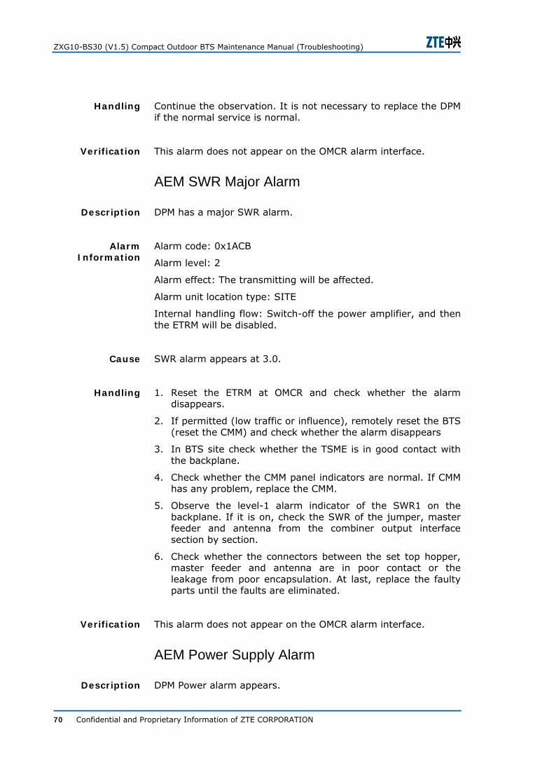
ZXG10-BS30 (V1.5) Compact Outdoor BTS Maintenance Manual (Troubleshooting)
70 Confidential and Proprietary Information of ZTE CORPORATION
Continue the observation. It is not necessary to replace the DPM if the normal service is normal.
This alarm does not appear on the OMCR alarm interface.
AEM SWR Major Alarm
DPM has a major SWR alarm.
Alarm code: 0x1ACB
Alarm level: 2
Alarm effect: The transmitting will be affected.
Alarm unit location type: SITE
Internal handling flow: Switch-off the power amplifier, and then the ETRM will be disabled.
SWR alarm appears at 3.0.
1. Reset the ETRM at OMCR and check whether the alarm disappears.
2. If permitted (low traffic or influence), remotely reset the BTS (reset the CMM) and check whether the alarm disappears
3. In BTS site check whether the TSME is in good contact with the backplane.
4. Check whether the CMM panel indicators are normal. If CMM has any problem, replace the CMM.
5. Observe the level-1 alarm indicator of the SWR1 on the backplane. If it is on, check the SWR of the jumper, master feeder and antenna from the combiner output interface section by section.
6. Check whether the connectors between the set top hopper, master feeder and antenna are in poor contact or the leakage from poor encapsulation. At last, replace the faulty parts until the faults are eliminated.
This alarm does not appear on the OMCR alarm interface.
AEM Power Supply Alarm
DPM Power alarm appears.
Handling
Verification
Description
Alarm Information
Cause
Handling
Verification
Description

Chapter 4-Common Faults
Confidential and Proprietary Information of ZTE CORPORATION 71
Alarm code: 0x1ACC
Alarm level: 2
Alarm effect: signal transmitting will be affected.
Alarm unit location type: Site
Internal handling flow: related ETRM is disabled.
DPM power supply has an alarm.
Replace the DPM in time.
This alarm does not appear on the OMCR alarm interface.
AEM Type Alarm
AEM type alarm appears.
Alarm code: 0x1ACE
Alarm level: 2
Alarm effect: transmitting performance will be affected.
Alarm unit location type: Site
Internal handling flow: related ETRM is disabled.
DPM type alarm appears.
1. Check whether the DPM configuration type matches the actual type. If not, replace the DPM module.
2. Check whether the DPM is plugged securely and powered on. Check whether the backplane transmission is faulty, and whether the ETRM collection circuit is faulty. If yes, replace the related cables or module.
This alarm does not appear on the OMCR alarm interface.
AEM absent Alarm
DPM not-in-position alarm appears.
Alarm Information
Cause
Handling
Verification
Description
Alarm Information
Cause
Handling
Verification
Description

ZXG10-BS30 (V1.5) Compact Outdoor BTS Maintenance Manual (Troubleshooting)
72 Confidential and Proprietary Information of ZTE CORPORATION
Alarm code: 0x1ACF
Alarm level: 2
Alarm effect: transmitting performance will be affected.
Alarm unit location type: SITE
DPM not-in-position alarm appears.
Replace the DPM, and reset the associated TRM.
This alarm does not appear on the OMCR alarm interface.
Backbone Node Alarm
Basic Chassis Power Supply Over/Under-voltage Alarm
The basic chassis power supply has over/under-voltage alarms.
Alarm code: It is user-defined within the range 0xF15 ~ 0xF20.
Alarm level: User defined.
Alarm effect: normal operation of the site will be affected.
Alarm unit location type: Site
Basic chassis power supply over/under-voltage.
Check the power supply conditions and power supply module.
This alarm does not appear on the OMCR alarm interface.
Basic Chassis Entrance Control Alarm
The basic chassis has entrance control alarms.
Alarm code: It is user-defined within the range 0xF15 ~ 0xF20.
Alarm level: User defined.
Alarm effect: None
Alarm Information
Cause
Handling
Verification
Description
Alarm Information
Cause
Handling
Verification
Description
Alarm Information

Chapter 4-Common Faults
Confidential and Proprietary Information of ZTE CORPORATION 73
Alarm unit location type: Site
Basic chassis door is opened.
If the door of the basic chassis is opened, close it.
This alarm does not appear on the OMCR alarm interface.
Extended Chassis 1 Power Supply Over/Under-voltage Alarm
Extended chassis 1 has power supply over/under-voltage alarms.
Alarm code: It is user-defined within the range 0xF15 ~ 0xF20.
Alarm level: User defined.
Alarm effect: The normal operation of extended chassis 1 will be affected.
Alarm unit location type: Site
The power supply of extended chassis 1 is over/under-voltage.
Check the power supply and power supply module conditions and perform corresponding handling.
This alarm does not appear on the OMCR alarm interface.
Extended Chassis 1 Entrance Control Alarm
Extended chassis 1 has entrance control alarms.
Alarm code: It is user-defined within the range 0xF15 ~ 0xF20.
Alarm level: User defined.
Alarm effect: None
Alarm unit location type: SITE
The door of extended chassis 1 is opened.
If the door of extended chassis 1 is opened, close it in time.
Cause
Handling
Verification
Description
Alarm Information
Cause
Handling
Verification
Description
Alarm Information
Cause
Handling

ZXG10-BS30 (V1.5) Compact Outdoor BTS Maintenance Manual (Troubleshooting)
74 Confidential and Proprietary Information of ZTE CORPORATION
This alarm does not appear on the OMCR alarm interface.
Extended Chassis 2 Power Supply Over/Under-voltage Alarm
Extended chassis 2 has power supply over/under-voltage alarms.
Alarm code: It is user-defined within the range 0xF15 ~ 0xF20.
Alarm level: User defined.
Alarm effect: The normal operation of extended chassis 2 will be affected.
Alarm unit location type: Site
The power supply of extended chassis 2 is over/under-voltage.
Check the power supply and power supply module conditions and perform corresponding handling.
This alarm does not appear on the OMCR alarm interface.
Extended Chassis 2 Entrance Control Alarm
Extended chassis 2 has entrance control alarms.
Alarm code: It is user-defined within the range 0xF15 ~ 0xF20.
Alarm level: User defined.
Alarm influence:
Alarm unit location type: SITE
The door of extended chassis 2 is opened.
If the door of extended chassis 2 is opened, close it in time.
This alarm does not appear on the OMCR alarm interface.
Verification
Description
Alarm Information
Cause
Handling
Verification
Description
Alarm Information
Cause
Handling
Verification

Confidential and Proprietary Information of ZTE CORPORATION 75
A p p e n d i x A
Replacement of Modules and Boards
Replacement of modules and boards is common procedure of routine maintenance. It is recommended to call ZTE technical staff for technical support and take necessary precautions described while replacing boards.
1. Spare parts should be kept in antistatic bag and placed properly in carton. Model number and version should be available on static bag or carton for easy identification.
2. Check whether spare board is physically damaged before replacement.
3. Anti static wrist strap should be used when the modules are replaced when holding module by hand try not to touch the circuit. Don’t plug or unplug board with violent force so as not to damage the backplane pins.
4. Replaced faulty board should be kept in anti static bag and stored properly.
5. Replace power module after properly Turing it off.
CMM Board Replacement
1. Use BS30 special key to open cabinet door.
2. Turn the power switch of PWM and PWDM switch to OFF position to turn OFF the BTS.
3. Unscrew the six captive screws on TSME protection plate and remove protection plate from CMM board along vertical position as shown in the Figure 1.
Pay Attention
Procedure
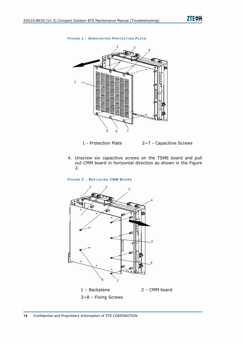
ZXG10-BS30 (V1.5) Compact Outdoor BTS Maintenance Manual (Troubleshooting)
76 Confidential and Proprietary Information of ZTE CORPORATION
F I G U R E 1 – DE M O U N T I N G PR O T E C T I O N P L AT E
1 - Protection Plate 2~7 - Capacitive Screws
4. Unscrew six capacitive screws on the TSME board and pull out CMM board in horizontal direction as shown in the Figure 2.
F I G U R E 2 - RE P L AC I N G CMM B O AR D
1 – Backplane 2 – CMM board
3~8 – Fixing Screws

Appendix A
Confidential and Proprietary Information of ZTE CORPORATION 77
5. Put removed faulty board in antistatic damper proof bag and mark it properly.
6. Insert spare CMM in position of faulty CMM and tighten six fixing screws.
7. Press protection plate on to CMM board according to original position and fix six capacitive screws.
8. Turn the PWM or PWDM switch to ON position to turn ON the BTS.
TSME Replacement
1. Put on the antistatic wrist strap and connect grounding terminal to equipment chassis securely.
2. Use BS 30 special key to open cabinet door.
3. Turn the power switch of PWM and PWDM switch to OFF position to turn OFF the BTS.
4. Disconnect cables connected to TSME and write down location of each cable connection.
5. Unscrew ten capacitive screws on TSME, remove TSME from main radiator and take out TSME as shown in the Figure 3.
6. Place the new TSME and tighten Ten capacitive screws to place TSME again.
F I G U R E 3 - RE P L AC I N G TSME
1~10 Capacitive Screws
Procedure

ZXG10-BS30 (V1.5) Compact Outdoor BTS Maintenance Manual (Troubleshooting)
78 Confidential and Proprietary Information of ZTE CORPORATION
7. Power on the TSME, and check whether TSME is in normal working condition.
Backplane Replacement
1. Put on the antistatic wrist strap and connect grounding terminal to equipment chassis.
2. Use BS 30 special key to open cabinet door.
3. Turn the power switch of PWM and PWDM switch to OFF position to turn OFF the BTS.
4. Remove the TSME as described in TSME Replacement
5. Unscrew screw driver and pull the backplane along direction as shown in the Figure 4.
F I G U R E 4 – BAC K P L AN E R E P L AC E M E N T
1~5 Fixing Screws 6- Backplane
6. Configure the switches and jumpers on the backplane according to the original setting and use five fixing screws to fix the backplane on the structural part of the TSME.
7. Fix the TSME on chassis as described in the TSME Replacement
8. Connect the cable to backplane according to location of each cable connection.
9. Turn on PWM switch to ON position turn ON the BTS.
10. After backplane is replaced, check whether TSME indicator to see whether they are in normal condition.
Procedure

Appendix A
Confidential and Proprietary Information of ZTE CORPORATION 79
The entire standing component is installed on front side of backplane. Backplane is connected to CMM and TRME through 2 mm Type A (5×22) and Type B (5×25) welding free socket and plug.
Hot plugging or unplugging of CMM is implemented by long grounded pins in the middle of the socket and hot plugging or unplugging of TRME is implemented by row-2 row-4 grounded long pin in the socket.
Environment monitoring and inter rack clock synchronization are connected through Type-D socket and plug.
Site ID is configured through DIP switches for more information please refer ZXG -10 BS 30 (V1.5) compact out door BTS Hardware Installation Manual.
Primary power supply of board is connected through three core primary supply socket and plug and then distributed to the board through type N-3 core power socket.
Power Module (PWM) Replacement
1. Use BS 30 special key to open cabinet door.
2. Turn the power switch of PWM and PWDM switch to OFF position to turn OFF the BTS.
3. Put on antistatic wrist strap and connect grounding terminal to equipment chassis.
4. Remove cables connected to PWM and mark their location.
5. Unscrew the fixing screws and take out the PWM as shown in the Figure 5.
6. Keep the faulty board in to antistatic bag and mark model number and program version carefully. Mark the board as “Faulty” and keep it in to carton.
7. Tighten two fixing screws (again) as shown in the Figure 5.
8. Connect all cables securely on PWM according to their marked locations.
9. Turn ON powers switch of PWM and PWDM to ON position to turn ON the BTS.
10. Check PWM or PWDM indicators and check whether PWM is working normally.
Key Components
Procedure

ZXG10-BS30 (V1.5) Compact Outdoor BTS Maintenance Manual (Troubleshooting)
80 Confidential and Proprietary Information of ZTE CORPORATION
F I G U R E 5 – PWM R E P L AC E M E N T
1 ~2 Fixing Screws
DUPLEXER MODULE (DPM) Replacement
1. Use BS 30 special key to open cabinet door.
2. Turn the power switch of PWM and PWDM switch to OFF position to turn OFF the BTS.
3. Put on antistatic wrist strap and connect grounding terminal to equipment chassis.
4. Before removing DPM remove PWM or PWDM for more information. Refer Power Module (PWM) Replacement
5. Disconnect all cables that are connected to DPM and mark their connection location carefully.
6. Unscrew seven fixing screws on main body of duplexer as shown in the Figure 6.
7. Keep the faulty board in to antistatic bag and mark model number and program version carefully. Mark the board as “Faulty” and keep it in to carton.
8. Replace faulty DPM by the spare board fixing screws again.
9. Connect cables to DPM according to their marked location.
10. Turn ON powers switch of PWM and PWDM to ON position to turn ON the BTS.
Procedure

Appendix A
Confidential and Proprietary Information of ZTE CORPORATION 81
F I G U R E 6 – DPM R E P L AC E M E N T
1 – Main body of duplexer 2~8 Fixing Screws
SDH Transmission Module (STM) Replacement
1. Use BS30 special key to open cabinet door
2. Turn the power switch of PWM or PWDM switch to OFF position to turn OFF the BTS.
3. Put on antistatic wrist strap and connect grounding terminal to equipment chassis.
4. Remove all cables connected to STM and mark their connection locations carefully.
5. Unscrew six fixing screws on STM, detach STM from door plate and take it out as shown in the Figure 7.
6. Keep the faulty board in to antistatic bag and mark model number and program version carefully. Mark the board as “Faulty” and keep it in to carton.
7. Replace the faulty STM by spare board and tighten the fixing screws.
8. Connect cable to STM according to their original marked locations.
Procedure

ZXG10-BS30 (V1.5) Compact Outdoor BTS Maintenance Manual (Troubleshooting)
82 Confidential and Proprietary Information of ZTE CORPORATION
F I G U R E 7 – STM R E P L AC E M E N T
1~6 Fixing Screws
9. Turn ON powers switch of PWM and PWDM to ON position to turn ON the BTS.
10. Observe STM after power on and check whether; it working normally.
Heat Transfer Module (HTM) Replacement
1. Use BS30 special key to open cabinet door
2. Turn the power switch of PWM and PWDM switch to OFF position to turn OFF the BTS.
3. Put on antistatic wrist strap and connect grounding terminal to equipment chassis.
4. Remove all cables connected to HTM and mark their connection locations carefully.
5. Unscrew Two capacitive screws on HTM and raise HTM about 10 mm high to detach it from right angle plate from chassis as shown in the Figure 8.
Procedure

Appendix A
Confidential and Proprietary Information of ZTE CORPORATION 83
F I G U R E 8 – HTM R E P L AC E M E N T
1~2 capacitive screws
6. Keep the faulty board in to antistatic bag and mark the board as “Faulty” and keep it in carton.
7. Insert the spare HTM downward in to hanging plate at right side of chassis and tighten capacitive screws again.
8. Connect all cables to HTM according to their original marked location.
9. Turn power switch of PWM or PWDM to ON position, and turn ON the BTS.
Trunk Cable Replacement
1. Make sure that BTS trunk cable is same as that of trunk cable to be replaced. Trunk cable is 75 ohm co-axial cable.
2. Check the label at both the sides of trunk cable for one - to one correspondence. One end connects to top of BTS cabinet and one connects to the trunk equipment.
3. Check the new trunk cable with multimeter to see whether the cables is continue and no open and short in cable.
4. Cut the cable clip of the trunk cable to be replaced, and unplug A_IN A_OUT (or D_ IN, D_OUT) connector of the old trunk cable at the bottom of the cabinet, and take out old trunk cable.
5. Put the faulty trunk cable in the antistatic bag and mark it properly as “Faulty Cable” and put it in to carton.
6. Connect new trunk cable according to label at the bottom of the cabinet. Make sure that transmission (TX) and receiving (RX) end of trunk cable are at the correct position.
Procedure

ZXG10-BS30 (V1.5) Compact Outdoor BTS Maintenance Manual (Troubleshooting)
84 Confidential and Proprietary Information of ZTE CORPORATION
7. Make sure that trunk cable insulation does not damage in the process.
RF Cable Replacement
1. Check whether grounding wire core of new cable is normal and make sure that SMA or N connector are in normal conditions.
2. Turn the power switch of PWM or PWDM switch to OFF position to turn OFF the BTS before replacing RF cables.
3. Mark RF cable properly (TX and RX of every sector).
4. Remove faulty RF cable by removing SMA or N type connectors of both sides.
5. Replace new RF cable according to former RF cable connection locations.
6. Mark new RF cable with TX and RX of each sector.
7. Power on the BS 30 BTS.
8. After replacement of RF cable check VSWR and check whether it is in permissible limit
9. .Perform call test and check whether BTS is working normally.
Note: Never use excessive force while handling connectors it might damage connector permanently.
Replacement of Antenna Feeder Lightning Arrestor
Straight screwdriver
Slip joint pliers
Adjustable wrenches
Multimeter
Site Master
Check whether new lightning arrestor is same as that of one to be replaced. Test new lightning arrestor through multimeter.
Set resistance to W %10K step to measure resistance between antenna and conductor in high frequency socket of the device it should be greater than 20 M Ohm.
Procedure
Tools
Procedure

Appendix A
Confidential and Proprietary Information of ZTE CORPORATION 85
Set the resistance to W%1K step to measure resistance in conductor of high frequency socket of the antenna and grounding terminal the value should be close to 0 Ohm.
Turn the power switch of PWM or PWDM switch to OFF position to turn OFF the BTS.
Remove jumper connector, feeder connector and remove old lightning arrestors.
Connect new lightning arrestor; and connect feeder cable to lightning arrestor.
Measure VSWR of feeder cable and check whether it is in permissible limits.
If VSWR is normal connect jumper cables.
Power on BS30; check whether it is running in normal state.
Perform call test to check whether BTS works normally after replacement.
Note: In the process of making antenna feeder cable
Wrap it with water proof tape, sealing tape and insulating tape in turn.
Wrap the tape from bottom to top of one layer of one layer after another to prevent rain water entering.
Replacement of ½ Inch Jumper Cables
LDF4 block cutting device
LDF4 block installation tools
Adjustable Wrenches
Hacksaw
Assorted File
Paper Knife
Hot air blower
Site Master
Multimeter
Turn the power switch of PWM or PWDM switch to OFF position to turn OFF BTS.
Remove jumper by adjustable wrench, and then remove jumper at two ends.
Tools
Procedure

ZXG10-BS30 (V1.5) Compact Outdoor BTS Maintenance Manual (Troubleshooting)
86 Confidential and Proprietary Information of ZTE CORPORATION
Cut the proper length of jumper cable and make new jumper cable for more detail refer ZXG 10 – BS 30 (V1.5) Compact Outdoor BTS Installation Manual
Test new jumper cable through multimeter for continuity.
Perform heat sinking on jumper cable with the help of hot air blower.
Connect new jumper cable; measure VSWR of jumper cable and check whether it is in permissible limits.
Power on BS 30
Observe running status of ETRM and DPM and check whether BTS is working normally.
Perform call test and check whether BTS is working normally.
Note: Jumper cable should be bent softly without, too large angle and bend radius is 15 times of jumper radius.
Replacement of Feeder Connectors
LDF4 block cutting device
LDF4 block installation tools
Adjustable Wrenches
Hacksaw
Assorted File
Paper Knife
Hot air blower
Site Master
Multimeter
Turn the power switch of PWM and PWDM to OFF position to turn OFF BTS.
Remove the connectors at both ends of cable with the help of adjustable wrench.
Prepare new connector for more detail refer ZXG 10 – BS 30 (V1.5) Compact Outdoor BTS Installation Manual
Power on the BS 30 BTS.
Measure VSWR of feeder cable to check whether it is in permissible limit.
Observe running status of ETRM and DPM and check whether BTS is working normally.
Perform call test and check whether BTS is working normally.
Tools
Procedure

Appendix A
Confidential and Proprietary Information of ZTE CORPORATION 87
Tower Mounted Amplifier Replacement
Adjustable Wrenches
Paper knife
Sharp nose pliers
Diagonal pliers compass
Compass
Angle instruments
Lifting tools
Safety climbing tools
Site master
Walk talky or mobile phone
Turn the power switch of PWM and PWDM to OFF position to turn OFF BTS.
Strip off layers of water proof tape of faulty tower amplifier by paper knife and sharp nose pliers. Remove old tower amplifier from the fixing clamp by socket wrench.
Fix new tower amplifier with the help of fixing clamp.
Connect end IN of the tower amplifier to antenna jumper and end OUT to 7/8 feeder jumper.
At the receiving end of Antenna Equipment Module (AEM) measure if current is 6o mA ~200 mA and make water proof treatment to connectors.
Power on BS 30 BTS.
Observe running status of ETRM and DPM and check whether BTS is working normally.
Perform call test and check whether BTS is working normally.
Note: Put two input ends of tower mounted amplifier downwards to prevent water from entering in it.
Antenna Replacement
Adjustable Wrenches
Paper knife
Sharp nose pliers
Diagonal pliers compass
Tools
Procedure
Tools

ZXG10-BS30 (V1.5) Compact Outdoor BTS Maintenance Manual (Troubleshooting)
88 Confidential and Proprietary Information of ZTE CORPORATION
Compass
Angle instruments
Lifting tools
Safety climbing tools
Site master
Walk talky or mobile phone
Turn the power switch of PWM and PWDM to OFF position to turn OFF BTS.
Strip off water proof tape on jumper cable remove jumper connector remove fixing clamp of antenna and remove the antenna.
Carefully lift new antenna installation tools to destination location with the help of lifting tool.
Connect jumper connector to antenna make waterproofing treatment to connector and seal them.
Place the antennas feed point in downward position and fix the antenna with the help of fixing clamp (do not fix it firmly).
Adjust the antenna horizontal angle (orientation) according to design requirement and fix antenna clamp firmly.
Adjust pitch angel according to design requirement.
Connect jumper cable to antenna feeder cable.
Check VSWR of antenna feeder cables and jumper cables and check whether it is in the permissible limits.
Perform heat sinking operation on jumper cables with the help of hot air blower.
In case of tower amplifier is installed check whether there is 60 ~ 200 mA current.
Power on the BS 30.
Observe running status of ETRM and DPM and check whether BTS is working normally.
Perform call test and check whether BTS is working normally.
Note: While lifting of antenna, person on the ground can pull guiding rope outside to avoid collision with the tower.
Procedure

Confidential and Proprietary Information of ZTE CORPORATION 89
A p p e n d i x B
Common Maintenance Tables
This section describes maintenance types carried by professional along with record tables for:
Daily Maintenance
Weekly Maintenance
Monthly Maintenance
Half Yearly Maintenance
Emergency Maintenance
T AB L E 11 – DAI L Y M AI N T E N AN C E T AB L E
Site No
Site Name
Operation
Equipment Running State
Conducted By
Remark

ZXG10-BS30 (V1.5) Compact Outdoor BTS Maintenance Manual (Troubleshooting)
90 Confidential and Proprietary Information of ZTE CORPORATION
T AB L E 12 – WE E K L Y M AI N T E N AN C E T AB L E
Site No
Site Name
Operation
Equipment Running State
Conducted By
Remark

Appendix B
Confidential and Proprietary Information of ZTE CORPORATION 91
T AB L E 13 – MO N T H L Y M AI N T E N AN C E T AB L E
Site No
Site Name
Operation
Equipment Running State
Conducted By
Remark
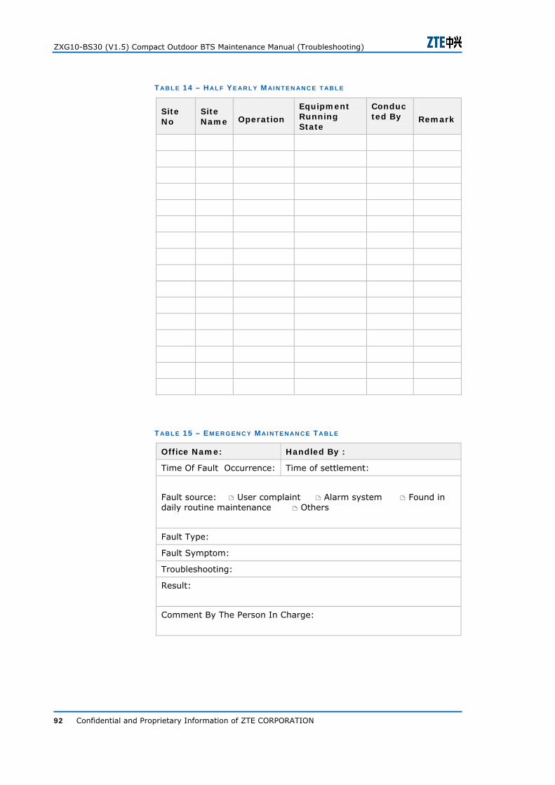
ZXG10-BS30 (V1.5) Compact Outdoor BTS Maintenance Manual (Troubleshooting)
92 Confidential and Proprietary Information of ZTE CORPORATION
T AB L E 14 – HAL F Y E AR L Y M AI N T E N AN C E T AB L E
Site No
Site Name
Operation
Equipment Running State
Conducted By
Remark
T AB L E 15 – EM E R G E N C Y MAI N T E N AN C E T AB L E
Office Name: Handled By :
Time Of Fault Occurrence: Time of settlement:
Fault source: User complaint Alarm system Found in daily routine maintenance Others
Fault Type:
Fault Symptom:
Troubleshooting:
Result:
Comment By The Person In Charge:
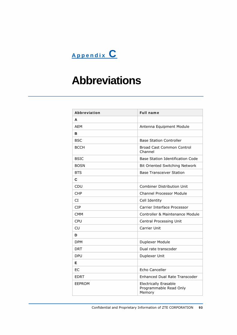
Confidential and Proprietary Information of ZTE CORPORATION 93
A p p e n d i x C
Abbreviations
Abbreviation Full name
A
AEM Antenna Equipment Module
B
BSC Base Station Controller
BCCH Broad Cast Common Control Channel
BSIC Base Station Identification Code
BOSN Bit Oriented Switching Network
BTS Base Transceiver Station
C
CDU Combiner Distribution Unit
CHP Channel Processor Module
CI Cell Identity
CIP Carrier Interface Processor
CMM Controller & Maintenance Module
CPU Central Processing Unit
CU Carrier Unit
D
DPM Duplexer Module
DRT Dual rate transcoder
DPU Duplexer Unit
E
EC Echo Canceller
EDRT Enhanced Dual Rate Transcoder
EEPROM Electrically Erasable Programmable Read Only Memory

ZXG10-BS30 (V1.5) Compact Outdoor BTS Maintenance Manual (Troubleshooting)
94 Confidential and Proprietary Information of ZTE CORPORATION
Abbreviation Full name
ETRM Extended Transceiver Module
F
FPGA Field Programmable Gate Array
FU Frame Unit
FUC Frame Unit Controller
H
HDLC High Level Data Link Controller
HTM Heat Transfer Module
HW Highway
I
IMEI International Mobile Equipment Identification
IMSI International Mobile Station Identification
L
LAC Location Area Code
LAI Location Area Identity
LAPD Link Access Procedure on “D” Channel
LMT Local Maintenance Terminal
M
MP Main Processor
P
PA Power Amplifier
PAS Power Amplifier Supply
PAU Power Amplifier Unit
PLMN Public Land Mobile Network
PSTN Public Switch Telephone Network
PWM AC Power Supply Module (220 V)
PWMD DC Power Supply Module (-48 V)
R
RCU Radio Carrier Unit
RDU Receiver Distribution Unit
S
SDCCH Stand Alone Dedicated Control Channel
SMB Short Message Broadcast
STM SDH Transmission Module

Appendix C
Confidential and Proprietary Information of ZTE CORPORATION 95
Abbreviation Full name
SWR Standing Wave Ratio
T
TIC Trunk Interface Circuit
TMA Tower Mounted Amplifier
TPU Transceiver Process Unit
TRAU Transcoder Rate Adaptation Unit
TRM Transceiver Module (40 W module)
TSME Transceiver Station Module For Edge
TRX Transceivers
V
VSWR Voltage Standing Wave Ratio

ZXG10-BS30 (V1.5) Compact Outdoor BTS Maintenance Manual (Troubleshooting)
96 Confidential and Proprietary Information of ZTE CORPORATION
This page is intentionally blank.

Confidential and Proprietary Information of ZTE CORPORATION 97
Figures
Figure 1 – Demounting Protection Plate ............................... 80
Figure 2 - Replacing CMM Board ........................................ 80
Figure 3 - Replacing TSME ................................................ 81
Figure 4 – Backplane Replacement...................................... 82
Figure 5 – PWM Replacement ............................................. 84
Figure 6 – DPM Replacement.............................................. 85
Figure 7 – STM Replacement.............................................. 86
Figure 8 – HTM Replacement.............................................. 87

ZXG10-BS30 (V1.5) Compact Outdoor BTS Maintenance Manual (Troubleshooting)
98 Confidential and Proprietary Information of ZTE CORPORATION
This page is intentionally blank.
Confidential and Proprietary Information of ZTE CORPORATION 99
Tables
Table 1 - Chapter Summary ..................................................i
Table 2 - Typographical Conventions ..................................... ii
Table 3 - Mouse Operation Conventions ................................ iii
Table 4 – General Safety Symbols.........................................2
Table 5 - CMM Board Clk LED Indicator Status ...................... 13
Table 6 – TIC Board E1 LED Indicator Status ........................ 13
Table 7 – CMM Board STA LED Indicator Status .................... 14
Table 8 – Default Value Of Parameters ................................ 16
Table 9 – Transmission Notification Alarms On BSC Side ........ 24
Table 10 - Alarm Levels.................................................... 39
Table 11 – Daily Maintenance Table .................................... 93
Table 12 – Weekly Maintenance Table ................................. 94
Table 13 – Monthly Maintenance Table ................................ 95
Table 14 – Half Yearly Maintenance table ............................. 96
Table 15 – Emergency Maintenance Table ............................ 96

ZXG10-BS30 (V1.5) Compact Outdoor BTS Maintenance Manual (Troubleshooting)
100 Confidential and Proprietary Information of ZTE CORPORATION
This page is intentionally blank.

Confidential and Proprietary Information of ZTE CORPORATION 101
Index
120 ohm twisted pair cable...15 52 M reference clock............62 75 ohm co –axial cable ........15 Abis synchronization failure ..12 acid liquid overflow................6 add/drop multiplexer ...........27 anti-static bag ......................5 antistatic wrist strap..............5 Backward slip code indication45 BER Meter..........................56 Bit Error Rate (BER) meter ...19 Bit Oriented Switching Network
(BOSN) ..........................30 Blind Area ..........................32 Cell Bar .............................13 Cell Identity (CI).................12 CI 13 CIP resource is unavailable ...50 CMM board CLK LED Indicator
....................................13 CMM boards STA LED indicators
....................................13 CMM FLASH programming fails
....................................40 CMM SYN LED indicator........21 CMMSYN LED indicator.........21 co-channel interference effect
....................................14 connection timeout, .........56 DIP switch ................... 14, 31 DIP switches ......................56 DUC chip initialization ..........68 E1 interface chip .................45 Echo Canceller (EC).............23 electromagnetic field .............5 electrostatic charge ...............5 electrostatic shock ................5 Equipment radiation design ....7 FLASH MEMORY failure alarm 50 Forward slip code indication..46
FPGA interface fault ............ 64 FUC’s L3 software ............... 55 Hand over Margin (HOMAGIN)
.................................... 33 High Level Data Link Control
(HDLC) .......................... 12 inter-symbol interference..... 26 IRXLEVDLH ........................ 32 IRXLEVULH ........................ 32 LAC .................................. 13 Location Area Code (LAC) .... 12 MS initial access signal level
(MsTxMaxCCH) ............... 15 MS Maximum Power Level
(MsTxPwrMax) ................ 15 MS minimum receiving signal
level.............................. 13 Network synchronization failure
.................................... 12 Out-of-synchronization alarm44 Rayleigh fading................... 22 RFAD6620 initialization fails . 49 RFAD6620 resource is
unavailable .................... 49 safety instructions ................1 Safety Symbols ....................1 self- loop test..................... 19 Site Master ........................ 14 T 3122 .............................. 31 T3103 ............................... 32 T3122 ............................... 31 T3212 ............................... 31 Transcoder Rate Adaptation
Unit (TRAU).................... 23 Transmission Faults............. 12 Trunk Interface Circuit (TIC)
board E1 LED indicator..... 13 universal alarm symbol..........2 WATCHDOG overflows ....51, 52