compact logix selection guide
TRANSCRIPT

8/6/2019 Compact Logix Selection Guide
http://slidepdf.com/reader/full/compact-logix-selection-guide 1/64
COMPACTLOGIX
CONTROLLERSSELECTION GUIDE
1769-L31
1769-L32C, 1769-L35CR
1769-L32E, 1769-L35E
1768-L43, 1768-L45

8/6/2019 Compact Logix Selection Guide
http://slidepdf.com/reader/full/compact-logix-selection-guide 2/64
Logix Controllers Comparison
Characteristic 1756 ControlLogix 1756 GuardLogix
1768
CompactLogix
1769
CompactLogix 1789 SoftLogix5800
PowerFlex 700S
Phase 2 with
DriveLogix
Controller tasks:• Continuous• Periodic• Event
• 100 tasks
• Event tasks: all eventtriggers
• 100 tasks
• Event tasks: all eventtriggers
• 16 tasks• Event tasks: consumed
tag, EVENT instruction,axis, and motion eventtriggers
• 1769-L35x: 8 tasks• 1769-L32x: 6 tasks• 1769-L31: 4 tasks• Event tasks: consumedtag and EVENT instructiontriggers
• 100 tasks• Event tasks: all eventtriggers, plus outboundand Windows events
• 8 tasks
• Event tasks: axis andmotion event triggers
User memory
1756-L55M12: 750 KB1756-L55M13: 1.5 MB1756-L55M14: 3.5 MB1756-L55M16: 7.5 MB1756-L55M22: 750 KB1756-L55M23: 1. 5 MB1756-L55M24: 3.5 MB1756-L60M03SE: 750 KB1756-L61: 2 MB1756-L62: 4 MB1756-L63: 8 MB1756-L64: 16 MB
1756-L61S:2 MB Standard1 MB Safety
1756-L61S:4 MB Standard1 MB Safety
1768-L43: 2 MB1768-L45: 3 MB
1769-L31: 512 KB1769-L32x: 750 KB1769-L35x: 1 .5 MB
1789-L10:2 MB; 1 controller; nomotion
1789-L30:64 MB; 3 controllers
1789-L60:64 MB; 6 controllers
1.5 MB
Nonvolatile user memory
1756-L55M12: none1756-L55M13: none1756-L55M14: none
1756-L55M16: none1756-L55M22: yes1756-L55M23: yes1756-L55M24: yes1756-L6x: CompactFlash
CompactFlash CompactFlash CompactFlash None CompactFlash
Built-in communicationports
1 port RS-232 s er ial 1 port RS-232 serial 1 port RS-232 serial
• 1769-L31: 2 RS-232ports• 1769-L32C, -L35CR: 1ControlNet port and 1 RS-232 serial port• 1769-L32E, -L35E: 1EtherNet/IP port and 1 RS-232 serial port
Depends on personalcomputer
• 1 port RS-232 serial
Communication options
• EtherNet/IP• ControlNet• DeviceNet• Data Highway Plus• Remote I/O• SynchLink
• EtherNet/IP (standardand safety)• ControlNet (standardand safety)• DeviceNet (standard
and safety)• Data Highway Plus• Remote I/O• SynchLink
• EtheNet/IP• ControlNet
• DeviceNet
• EtherNet/IP• ControlNet
• DeviceNet
• EtherNet/IP• ControlNet
• DeviceNet
• EtherNet/IP• ControlNet
• DeviceNet
Serial port communication
• ASCII• DF1 full/half-duplex• DF1 radio modem• DH-485• Modbus via logic
• ASCII• DF1 full/half-duplex• DF1 radio modem• DH-485• Modbus via logic
• ASCII• DF1 full/half-duplex• DF1 radio modem• DH-485• Modbus via logic
• ASCII• DF1 full/half-duplex• DF1 radio modem• DH-485• Modbus via logic
• ASCII• DF1 full/half-duplex• DH-485• Modbus via logic
• ASCII• DF1 full/half-duplex• DF1 radio modem• DH-485• Modbus via logic
Controller connections 250 250 250 100 250 100
Network connections
Per network module:• 100 ControlNet (CN2/A)• 40 ControlNet (CNB)• 256 EtherNet/IP; 128TCP (EN2x )• 128 EtherNet/IP; 64 TCP(ENBT)
Per network module:• 100 ControlNet (CN2/A)• 40 ControlNet (CNB)• 256 EtherNet/IP; 128TCP (EN2x )• 128 EtherNet/IP; 64 TCP(ENBT)
Per network module:• 48 ControlNet• 64 EtherNet/IP; 32 TCP
Per controller:• 32 ControlNet• 32 EtherNet/IP; 32 TCP
Per network module:• 48 ControlNet• 128 EtherNet/IP; 64 TCP
Per network module:• 32 ControlNet• 32 EtherNet/IP; 32 TCP
Controller redundancy Full support None Backup via DeviceNet Backup via DeviceNet NA NA
Simple motion• Stepper• Servo via DeviceNet• Analog ac drive
• Stepper• Servo via DeviceNet• Analog ac drive
• Stepper• Servo via DeviceNet• Analog ac drive
• Stepper• Servo via DeviceNet• Analog ac drive
• Stepper• Servo via DeviceNet• Analog ac drive
• Stepper• Servo via DeviceNet• Analog ac drive
Integrated motion
SERCOS interfaceAnalog options:• Encoder input• LDT input• SSI input
SERCOS interfaceAnalog options:• Encoder input• LDT input• SSI input
SERCOS interface NASERCOS interfaceAnalog encoder input
• 1 full servo• 1 feedback axis
Programming languages
• Relay ladder• Structured text• Function block• SFC
• Relay ladder• Structured text• Function block• SFC
• Relay ladder• Structured text• Function block• SFC
• Relay ladder• Structured text• Function block• SFC
• Relay ladder• Structured text• Function block• SFC• External routines(developed in C/C++)
• Relay ladder• Structured text• Function block• SFC

8/6/2019 Compact Logix Selection Guide
http://slidepdf.com/reader/full/compact-logix-selection-guide 3/64
3
1769-SG001G-EN-P -- July 2007
CompactLogix Selection Guide
Logix Platforms Allen-Bradley Logix platforms provide a single integrated-control architecture for discrete,
drives, motion, process, and safety control.
The Logix platforms provide a common control engine, programming software
environment, and communication support across multiple hardware platforms. All Logix
controllers operate with a multitasking, multiprocessing operating system and support the
same set of instructions in multiple programming languages. One RSLogix 5000
programming-software package programs all Logix controllers. And, as part of the
Integrated Architecture, all Logix controllers offer the benefits of the Common Industrial
Protocol (CIP) to communicate via EtherNet/IP, ControlNet, and DeviceNet networks.
Section Page
CompactLogix System Overview 4
CompactLogix Controllers 7
Network Communication 17
Motion Requirements 29
1769 I/O Modules 33
Power Supplies 41
Mounting 45
View Products 51
Software 53
8/6/2019 Compact Logix Selection Guide
http://slidepdf.com/reader/full/compact-logix-selection-guide 4/64
4
1769-SG001G-EN-P -- July 2007
CompactLogix Selection Guide
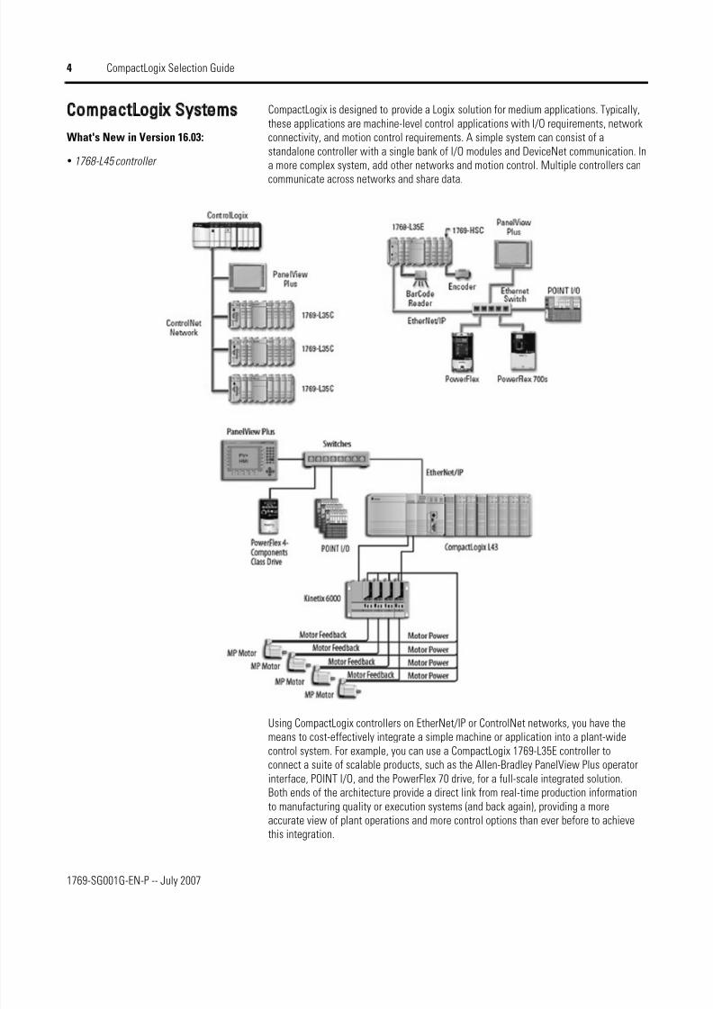
CompactLogix Systems CompactLogix is designed to provide a Logix solution for medium applications. Typically,
these applications are machine-level control applications with I/O requirements, network
connectivity, and motion control requirements. A simple system can consist of a
standalone controller with a single bank of I/O modules and DeviceNet communication. In
a more complex system, add other networks and motion control. Multiple controllers can
communicate across networks and share data.
What's New in Version 16.03:
1768-L45 controller
Using CompactLogix controllers on EtherNet/IP or ControlNet networks, you have the
means to cost-effectively integrate a simple machine or application into a plant-wide
control system. For example, you can use a CompactLogix 1769-L35E controller to
connect a suite of scalable products, such as the Allen-Bradley PanelView Plus operator
interface, POINT I/O, and the PowerFlex 70 drive, for a full-scale integrated solution.
Both ends of the architecture provide a direct link from real-time production information
to manufacturing quality or execution systems (and back again), providing a more
accurate view of plant operations and more control options than ever before to achieve
this integration.

8/6/2019 Compact Logix Selection Guide
http://slidepdf.com/reader/full/compact-logix-selection-guide 5/64

8/6/2019 Compact Logix Selection Guide
http://slidepdf.com/reader/full/compact-logix-selection-guide 6/64
6
1769-SG001G-EN-P -- July 2007
CompactLogix Selection Guide
Specify a System Follow these steps as you specify your CompactLogix system.
Step See
1 Select controllers.
Select the appropriate controller based on:
• required controller tasks.
• number of I/O points needed.
• number of communication cards needed.
• required controller memory.
Controller specifications page 7
Determine memory requirements page 8
1769-L3x controller placement page 9
1768-L4x controller placement page 10
Compatibility page 12
Logix system connections page 14
2 Select communication modules.
Add the number of communication modules to the systemspreadsheet.
Network overview page 17
EtherNet/IP specifications page 19
ControlNet specifications page 22
DeviceNet specifications page 24
Serial specifications page 26
DH-485 specifications page 283 Select motion control and drives requirements.
Add the motion module to the system spreadsheet.
Motion overview page 27
Integrated motion page 27
Networked motion page 28
4 Select I/O devices.
Use a system spreadsheet to record:
• number of points needed.
• number of points available per module.
• number of modules.
I/O module specifications page 32
Wiring systems page 39
Place I/O modules page 40
5 Select power supplies.
Calculate power requirements on the system spreadsheet.
1769 power supply specifications page 41
1768 power supply specifications page 43
6 Mount the system.
Determine whether to panel mount or DIN-rail mount theCompactLogix system.
1769 CompactLogix dimensions page 45
1768 CompactLogix dimensions page 48
7 Select view products.
Determine the visualization products that fit your operatorinterface needs.
RSView software page 51
PanelView Plus terminals page 52
PanelView CE industrial computers page 52
VersaView industrial computers page 52
8 Select software.
Determine the software products you need to configure andprogram your application.
Available software products page 53
Programming software page 55
Communication software page 56Network configuration software page 58
Emulation software page 60

8/6/2019 Compact Logix Selection Guide
http://slidepdf.com/reader/full/compact-logix-selection-guide 7/64
7
1769-SG001G-EN-P -- July 2007
CompactLogix Selection Guide
Step 1 - Select:
A controller with sufficient memory
A 1784-CF64 CompactFlash card
Replacement batteries for 1769-L3x
controllers (no battery needed for
1768-L4x controllers)
CompactLogix Controllers
The CompactLogix platform brings together the benefits of the Logix platform — common
programming environment, common networks, common control engine — in a small
footprint with high performance. Combined with Compact I/O, the CompactLogix platform
is perfect for tackling smaller, machine-level control applications, with or without simple
motion, with unprecedented power and scalability. CompactLogix is ideal for systems that
require standalone and system-connected control over EtherNet/IP, ControlNet, or
DeviceNet networks.
1769-L3x CompactLogix Controllers 1768-L4x CompactLogix Controllers
Controller application
General purpose
Single RPI for all modules
Integrated motion
Select individual RPI for each module
Controller tasks
• 1769-L35x: 8 tasks
• 1769-L32x: 6 tasks
• 1769-L31: 4 tasks
• Only 1 continuous
• Event tasks: consumed tag and EVENTinstruction triggers
• 16 tasks (only 1 continuous)
• Event tasks: consumed tag, EVENTinstruction, axis, and motion event triggers
User memory
1769-L31: 512 KB
1769-L32x: 750 KB
1769-L35x: 1.5 MB
1768-L43:2 MB
1768-L45:3 MB
Programming languages
Relay ladder
Function block diagramStructured text
Sequential function block
Relay ladder
Function block diagramStructured text
Sequential function block
Built-in communication ports
• 1769-L31: 2 RS-232 ports (one DF1 only,other DF1 or ASCII)
• 1769-L32C, 1769-L35CR: 1 ControlNet portand 1 RS-232 serial port (DF1 or ASCII)
• 1769-L32E, 1769-L35E: 1 EtherNet/IP portand 1 RS-232 serial port (DF1 or ASCII)
1 port RS- 232 serial
(DF1 or ASCII)
Communication options
• EtherNet/IP
• ControlNet
• DeviceNet
• EtherNet/IP
• ControlNet
• DeviceNet
Serial port communication
• ASCII• DF1 full/half duplex
• DF1 radio modem
• DH-485
• Modbus via logic
• ASCII• DF1 full/half duplex
• DF1 radio modem
• DH-485
• Modbus via logic

8/6/2019 Compact Logix Selection Guide
http://slidepdf.com/reader/full/compact-logix-selection-guide 8/64
8
1769-SG001G-EN-P -- July 2007
CompactLogix Selection Guide
CompactLogixControllers
Estimate Controller Memory Use
The following equations provide an estimate of the memory needed for a controller.
Controller Tasks _____ * 4000 =_____ bytes
(minimum 1 task)
Digital I/O points _____ * 400 = _____ bytes
Analog I/O points _____ * 2600 = _____ bytes
Communication modules _____ * 2000 = _____ bytes
Motion axes _____ * 8000 = _____ bytes
FactoryTalk alarm instruction _____ * 1000 =_____ bytes
(per alarm)
FactoryTalk subscriber_____ *10000
=_____ bytes
(per subscriber)
When estimating memory use by communication modules, count all the communication modules in the system, not just those in the localchassis. This includes device connection modules, adapter modules, and ports on PanelView terminals.
Characteristic 1769-L31 1769-L32C 1769-L32E 1769-L35CR 1769-L35E 1768-L43 1768-L45
Available UserMemory (Kbytes) 512 KB 750 KB 750 KB 1.5 MB 1.5 MB 2 MB 3 MB
CompactFlash Card• 1784-CF64 64 MB• 1784-CF128 128 MB
• 1784-CF64 64 MB• 1784-CF128 128 MB
• 1784-CF64 64 MB• 1784-CF128 128 MB
• 1784-CF64 64 MB• 1784-CF128 128 MB
• 1784-CF64 64 MB• 1784-CF128 128 MB
• 1784-CF64 64 MB• 1784-CF128 128 MB
• 1784-CF64 64 MB• 1784-CF128 128 MB
Communication Ports2 RS-232 ports (oneDF1 only, other DF1 orASCII)
1 ControlNet port and1 RS-232 serial port(DF1 or ASCII)
1 EtherNet/IP port and1 RS-232 serial port(DF1 or ASCII)
1 ControlNet port and1 RS-232 serial port(DF1 or ASCII)
1 EtherNet/IP port and1 RS-232 serial port(DF1 or ASCII)
1 RS-232 port 1 RS-232 port
Backplane Current(mA) at 5V
330 mA 680 mA 660 mA 680 mA 660 mA
0 A1768 output• 2.8 A @ 5.2V
1769 output• 2.0 A @ 5.2V
0 A1768 output• 2.8 A @ 5.2V
1769 output• 2.0 A @ 5.2V
Backplane Current(mA) at 24V
40 mA 40 mA 90 mA 40 mA 90 mA1.3 A1769 output• 1.0 A @ 24V
1.3 A1769 output• 1.0 A @ 24V
Power Dissipation 2.61 W 4.36 W 4.74 W 4.36 W 4.74 W 6.3 W 6.3 W
Module Capacity 16 1769 modules 30 1769 modules 30 1769 modules • Two 1768 modules• 16 1769 modules • Four 1768 modules• 30 1769 modules
Power Supply DistanceRating
4 modules 4 modules 4 modules NA NA

8/6/2019 Compact Logix Selection Guide
http://slidepdf.com/reader/full/compact-logix-selection-guide 9/64
9
1769-SG001G-EN-P -- July 2007
CompactLogix Selection Guide
Controller Battery
The 1769 controller comes with one 1769-BA lithium battery.
The 1768 controller does not require a battery. The controller uses internal flash memory
to store its program during shutdown. Energy stored in the 1768 power supply maintains
controller power long enough to store the program to internal flash memory (not the
external CompactFlash card).
CompactFlash Card
The CompactFlash card offers nonvolatile memory (flash) to permanently store a user
program and tag data on a controller.
1784-CF64 has 64 MB of memory.
1784-CF128 has 128 MB of memory.
1769-L3x ControllerPlacement
The controller and I/O modules can be placed to the left and the right of the power
supply. As many as eight modules can be placed on each side of the power supply.
The CompactLogix controller has a power supply distance rating of 4 modules. The
controller must be the leftmost module in the first bank of the system. The maximum
configuration for the first bank of a CompactLogix controller is the controller and 3 I/O
modules to the left of the power supply and 8 I/O modules to the right of the power
supply.
8/6/2019 Compact Logix Selection Guide
http://slidepdf.com/reader/full/compact-logix-selection-guide 10/64
10
1769-SG001G-EN-P -- July 2007
CompactLogix Selection Guide
1769-L3x Local I/O Performance
There is one RPI for the entire 1769 backplane (1...750 ms). As you install modules, the
minimum backplane RPI increases. The RPI (request packet interval) defines the frequency
at which the controller sends and receives all I/O data on the backplane.
Type ofModule Considerations
Digital and analog(any mix)
1...4 modules can be scanned in 1.0 ms
5...16 modules can be scanned in 1.5 ms
17...30 modules can be scanned in 2.0 ms
some input modules have a fixed 8.0 ms filter, so selectinga faster RPI has no affect
Specialty
full-sized 1769-SDN modules, addional 1.5 ms per module
1769-HSC modules, additional 0.5 ms per module
1769-ASCII modules, minimum of 8 ms per module
You can always select an RPI that is slower than listed above. These considerations show
how fast modules can be scanned - not how fast an application can use the data. The RPI
is asynchronous to the program scan. Other factors, such as program execution duration,
affect I/O throughput.
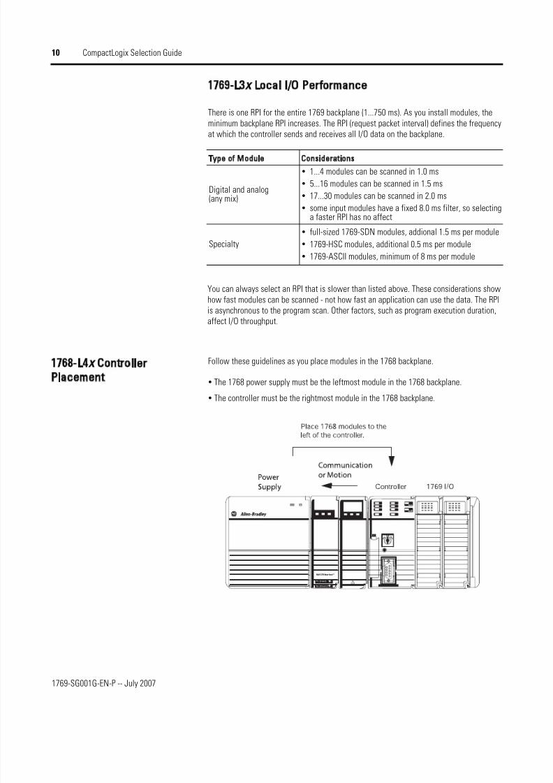
1768-L4x ControllerPlacement
Follow these guidelines as you place modules in the 1768 backplane.
The 1768 power supply must be the leftmost module in the 1768 backplane.
The controller must be the rightmost module in the 1768 backplane.

8/6/2019 Compact Logix Selection Guide
http://slidepdf.com/reader/full/compact-logix-selection-guide 11/64
11
1769-SG001G-EN-P -- July 2007
CompactLogix Selection Guide
Follow these guidelines as you place 1769 modules to the right of the 1768 backplane.
As many as eight 1769 modules can be attached to the right of the 1768 system.
The 1769 I/O connected directly to the 1768 backplane does not need a 1769 power
supply. Never put a 1769 power supply in the 1768 system. Putting a 1769 power
supply in the 1768 system causes the controller to generate a major fault that cannotbe cleared until you remove the 1769 power supply.
Additional 1769 modules must be in additional I/O banks.
Each additional I/O bank must have its own 1769 power supply.
Configure an individual RPI for each local 1769 I/O module. Use the default RPI numbers
that the software automatically assigns or select faster RPIs as fast as 1 millisecond. I/O
update times do not affect overall 1768 bus performance, such as motion performance or
controller performance.
Use faster RPIs for time critical I/O without impacting overall 1769 I/O performance.
Use Immediate Output (IOT) instructions for further reduction in I/O update times.
1768-L4x Local I/O Performance

8/6/2019 Compact Logix Selection Guide
http://slidepdf.com/reader/full/compact-logix-selection-guide 12/64

8/6/2019 Compact Logix Selection Guide
http://slidepdf.com/reader/full/compact-logix-selection-guide 13/64
13
1769-SG001G-EN-P -- July 2007
CompactLogix Selection Guide
Communicate with Other ControllersThe CompactLogix controllers can communicate with these controllers.
Controller EtherNet/IP✶ ControlNet DeviceNet RS-232 (DF1) DH-485
1756 ControlLogix1756 GuardLogix
Yes Yes Yes Yes Yes
1768 CompactLogix Yes Yes Yes Yes Yes
1769 CompactLogix Yes Yes Yes Yes Yes
1789 SoftLogix5800 Yes Yes Yes Yes No
1794 FlexLogix Yes Yes Yes Yes Yes
5720 PowerFlex 700SDriveLogix
Yes Yes Yes Yes No
1785 PLC-5 Yes‡ Yes§ Yes♣ Yes NA
1747 SLC Yes➤ Yes➤ Yes♣ Yes Yes
1761 MicroLogix Yes No Yes♣ Yes Yes
1762 MicroLogix Yes No Yes♣ Yes Yes1764 MicroLogix Yes No Yes♣ Yes Yes
1772 PLC-2 NA NA NA Yes NA
1775 PLC-3 NA NA NA Yes NA
5250 PLC-5/250 No No NA Yes NA
✶A non-EtherNet/IP controller requires a 1761-NET-ENI interface to connect to an EtherNet/IP network. This interface is only a messaging bridge.In the CompactLogix system, use either a 1769-SDN scanner (control I/O and send/receive messages) or a 1761-NET-DNI interface (messaging bridge).‡The Ethernet PLC-5 processor must be series C, firmware revision N.1 or later; series D, firmware revision E.1 or later; or series E, firmware revision D.1 or later.§The 1785-CNET ControlNet communication interface module must be series A, firmware revision D or later.
♣The PLC-5, SLC, and MicroLogix processors appear as I/O points to the Logix controller. Use the appropriate DeviceNet interface for the controller.➤Use a 1747-L55x controller with fir mware revision OS501 or later.
The PLC-2 controller requires a 1771-KG module for serial (DF1) communication.
The PLC-3 controller requires a 1775-KA module for serial (DF1) communication.
Communicate with Other Communication DevicesThe CompactLogix controllers can communicate with these communication devices.
Communication
Device EtherNet/IP✶ ControlNet DeviceNet RS-232 (DF1) DH-485
9355 RSLinx software Yes Yes Yes Yes Yes
1784-KTC, 1784-KTCx , 1784-KTCx 15,1784-PCIC(S), 1784-PCC
NA Yes NA NA NA
1784-PCIDS, 1784-PCD
NA NA Yes NA NA
1788-CN2DN NA Yes Yes NA NA1788-EN2DN Yes NA Yes NA NA
1788-CN2FF NA Yes NA NA NA
1203-CN1 ControlNetmodule‡
NA Yes NA NA NA
1203-FM1/FB1SCANport§
NA NA NA NA NA
✶A non-EtherNet/IP CompactLogix controller requires a 1761-NET-ENI interface to connect to an EtherNet/IP network. This interface is only a messaging bridge.
For DeviceNet access, use either a 1769-SDN scanner (control I/O and send/receive messages) or a 1761-NET-DNI interface (messaging bridge).‡Use the generic module configuration to configure the 1203-CN1 module and a CIP generic MSG instruction to communicate with the module.§Use a CIP generic MSG instr uction to communicate with the 1203-FM1 SCANport module on a DIN rail that is remote to the controller. The remote DIN r ail also requires a 1794-ACN(R)15 ControlNet adapter module.

8/6/2019 Compact Logix Selection Guide
http://slidepdf.com/reader/full/compact-logix-selection-guide 14/64
14
1769-SG001G-EN-P -- July 2007
CompactLogix Selection Guide
How a Logix SystemUses Connections
A Logix system uses a connection to establish a communication link between two
devices. Connections can be:
controller to local I/O modules or local communication modules.
controller to remote I/O or remote communication modules.
controller to remote I/O (rack-optimized) modules.
produced and consumed tags.
messages.
You indirectly determine the number of connections the controller uses by configuring the
controller to communicate with other devices in the system.
Method Description
Scheduled connection
• Highest level of determinism
• Unique to the ControlNet network
A scheduled connection is unique to ControlNet communication. A scheduled connectionlets you send and receive data repeatedly at a predetermined interval, which is therequested packet interval (RPI). For example, a connection to an I/O module is a scheduledconnection because you repeatedly receive data from the module at a specified interval.Other scheduled connections include connections to:
communication devices.
produced/consumed tags.
On a ControlNet network, you must use RSNetWorx for ControlNet software to enable allscheduled connections and establish a network update time (NUT).
Unscheduled connection
• Deterministic
• Used by both ControlNet and EtherNet/IPnetworks
An unscheduled connection is a message transfer between controllers that is triggered bythe requested packet interval (RPI) or the program (such as a MSG instruction).Unscheduled messaging lets you send and receive data when needed.
All EtherNet/IP connections are unscheduled.
Unconnected message
• Least deterministicAn unconnected message is a message that does not require connection resources. Anunconnected message is sent as a single request/response.
8/6/2019 Compact Logix Selection Guide
http://slidepdf.com/reader/full/compact-logix-selection-guide 15/64
15
1769-SG001G-EN-P -- July 2007
CompactLogix Selection Guide
1768 CompactLogix Connections
The total connection requirements for a 1768 CompactLogix system include both local and
remote (distributed) connections. The controller supports 250 connections. The available
remote connections depend on the network interface.
1769 CompactLogix Connections
The controller you select determines the connections for I/O and messages.
This controller Supports
1769-L32C
1769-L35CR32 CIP connections
1769-L32E
1769-L35E
32 CIP connections
32 TCP/IP connections
This communication
module Supports
1768-ENBT
1756-EWEB
64 CIP connections
32 TCP/IP connections
1768-CNB
1768-CNBR48 CIP connections
The total connection requirements for a 1769 CompactLogix system include both local and
remote (distributed) connections. The controller supports 100 connections. The available
remote connections depend on the network interface.

8/6/2019 Compact Logix Selection Guide
http://slidepdf.com/reader/full/compact-logix-selection-guide 16/64
16
1769-SG001G-EN-P -- July 2007
CompactLogix Selection Guide
Determine TotalConnection Use
Connection Type Device QuantityConnections perDevice
TotalConnections
Remote Ethernnet/IP communication module
configured as a direct (none) connection
configured as a rack-optimized connection
0 or
1
Remote I/O module over EtherNet/IP network (direct connection) 1
Remote ControlNet communication module
configured as a direct (none) connection
configured as a rack-optimized connection
0 or
1
Remote I/O module over ControlNet network (direct connection) 1
Remote device over DeviceNet network
(accounted for in rack-optimized connection for local 1769-SDN module)
0
Produced tag
Each consumer
1
1
Consumed tag 1
Message 1
RSLinx Enterprise subscriber (16 maximum) 1
Total
The total connection requirements for a CompactLogix system include both local and
remote (distributed) connections. The 1769-L3x controller supports 100 connections; the
1768-L4x controller supports 250 connections. The available remote connections depends
on the network interface.

8/6/2019 Compact Logix Selection Guide
http://slidepdf.com/reader/full/compact-logix-selection-guide 17/64

8/6/2019 Compact Logix Selection Guide
http://slidepdf.com/reader/full/compact-logix-selection-guide 18/64
18
1769-SG001G-EN-P -- July 2007
CompactLogix Selection Guide
Available Networks You can configure your system for information exchange between a range of devices and
computing platforms and operating systems. Select a CompactLogix controller with
integrated communication or the appropriate communication device for the networks that
meet your needs.
If your application requires Use this network 1769-L3x controller 1768-L4x controller
• Plant management
• Configuration, data collection, and control ona single, high-speed network
• Time-critical applications with no establishedschedule
• Data sent regularly
• Internet/Intranet connection
EtherNet/IP network• 1769-L32E controller
• 1769-L35E controller
• 1768-ENBT scanner
• 1768-EWEB interface
• Deterministic and repeatable data delivery
• Redundant media
• Intrinsic safety
• Internet/Intranet connection
ControlNet network
• 1769-L32C controller(nonredundant media)
• 1769-L35CR controller
(redundant media)
• 1768-CNB scanner(nonredundant media)
• 1768-CNBR scanner
(redundant media)
• Connections of low-level devices directly toplant floor controllers, without interfacing themthrough I/O modules
• Data sent as needed
• More diagnostics for improved data collectionand fault detection
• Less wiring and reduced start-up time than atraditional, hard-wired system
DeviceNet network• 1769-SDN scanner
• 1769-ADN adapter
• Modems
• Supervisory control and data acquisition
(SCADA)• Manipulate ASCII data
Serial network• Built-in serial port on the controller
• 1769-ASCII module
• Connections to existing DH-485 networks DH-485 network Built-in serial port with a 1761-NET-AIC

8/6/2019 Compact Logix Selection Guide
http://slidepdf.com/reader/full/compact-logix-selection-guide 19/64
19
1769-SG001G-EN-P -- July 2007
CompactLogix Selection Guide
EtherNet/IP Network The Ethernet Industrial (EtherNet/IP) network protocol is an open industrial-networking
standard that supports both real-time I/O messaging and message exchange. It emerged
due to the high demand for using the Ethernet network for control applications. The
EtherNet/IP network uses off-the-shelf Ethernet communication chips and physical media.
The EtherNet/IP network provides excellent drive and I/O control performance along with
HMI information processing and many commercial technologies.
Select an EtherNet/IP Interface
Select the appropriate controller and EtherNet/IP interface depending on the application
and how the controller interacts with the devices.
EtherNet/IP Interface Specifications
Cat. No.
Communication
Rate
Connections
Supported, Max.
Number of
Modules per
Controller
Power
Dissipation
Backplane
Current (mA) at
5V
Backplane
Current (mA) at
24V
Power Supply
Distance Rating
1768-ENBT
10/100 MB
Each module supports amaximum of:• 64 Logix (CIP) connections(I/O and information).• 32 TCP/IP connections.
two 1768 modules percontroller
4.38 W 834 mA 0 mA NA
1768-EWEB
1769-L32E
10/100 Mbps
Each module ports amaximum of:• 32 TCP/IP connections.
• 32 Logix connections (I/Oand information).
integrated controllerport
4.74 W 660 mA 90 mA 4 modules
1769-L35E
Certifications: c-UL-us (Class I, Division 2, Group A, B, C, D), CE, C-TickSee the Product Certifications link at http://ab.com for Declarations of Conformity, Certifications, and other certifications details.
The 1768-L4x controllers support a maximum of two 1768 communication modules per controller.
If your application Select for a 1769-L3x controller Select for a 1768-L4x controller• Controls I/O modules
• Requires an adapter for distributed I/O on EtherNet/IPlinks
• Communicates with other EtherNet/IP devices(messages)
• Bridges EtherNet/IP links to route messages to deviceson other networks
1769-L32E or 1769-L35E controllerwith integrated EtherNet/IP port
1768-ENBT scanner module
• Requires remote access via an internet browser to tagsin a local chassis
• Supports custom Web pages
• Bridges EtherNet/IP links to route messages to deviceson other networks
NA 1768-EWEB

8/6/2019 Compact Logix Selection Guide
http://slidepdf.com/reader/full/compact-logix-selection-guide 20/64
20
1769-SG001G-EN-P -- July 2007
CompactLogix Selection Guide
Example 1769-L32E, 1769-L35E EtherNet/IP Configuration
8/6/2019 Compact Logix Selection Guide
http://slidepdf.com/reader/full/compact-logix-selection-guide 21/64
21
1769-SG001G-EN-P -- July 2007
CompactLogix Selection Guide
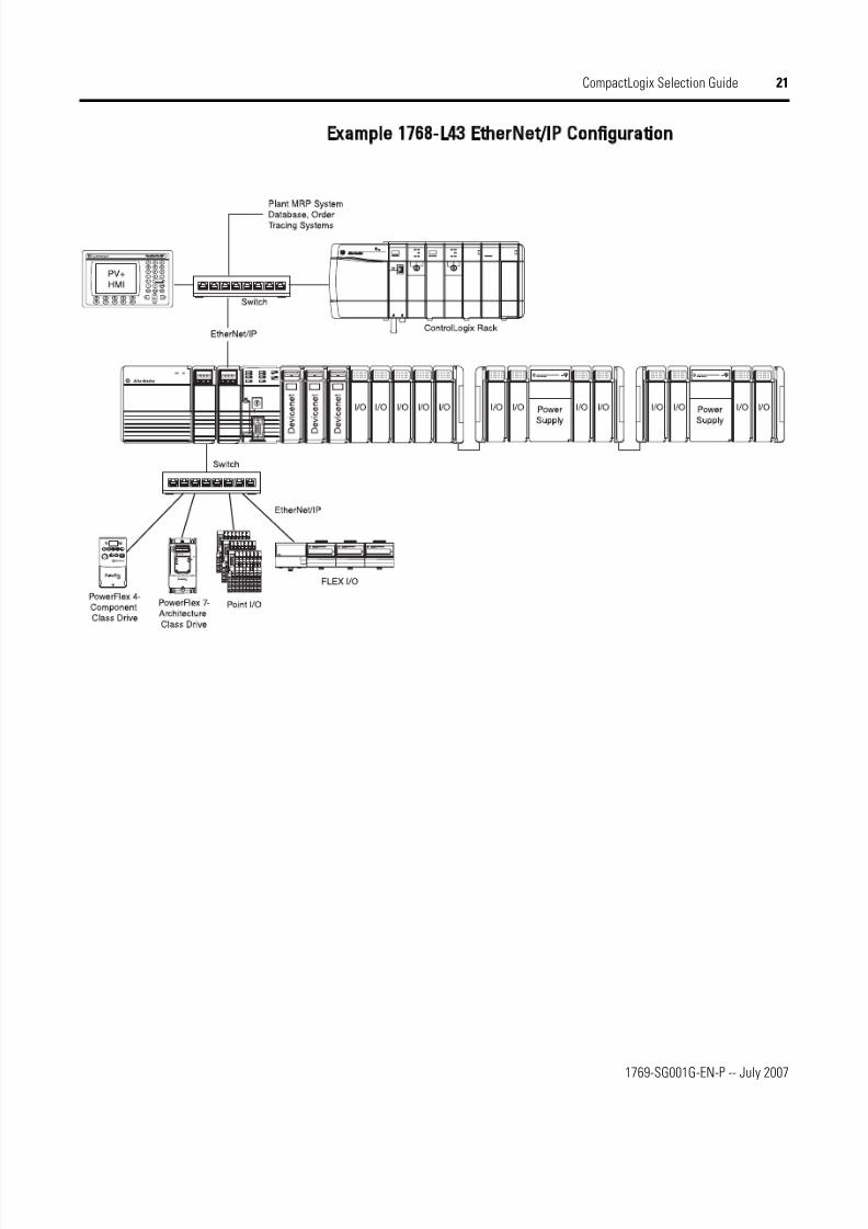
Example 1768-L43 EtherNet/IP Configuration

8/6/2019 Compact Logix Selection Guide
http://slidepdf.com/reader/full/compact-logix-selection-guide 22/64
22
1769-SG001G-EN-P -- July 2007
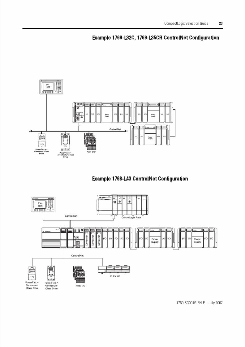
CompactLogix Selection Guide
ControlNet Network The ControlNet network is an open, state-of-the-art control network that meets the
demands of real-time, high-throughput applications. The ControlNet network uses the
proven Common Industrial Protocol (CIP) to combine the functionality of an I/O network
and a peer-to-peer network providing high-speed performance for both functions.
The ControlNet network gives you deterministic, repeatable transfers of all mission-criticalcontrol data in addition to supporting transfers of non-time-critical data. I/O updates and
controller-to-controller interlocking always take precedence over program uploads and
downloads and messaging.
Select a ControlNet Interface
Select the appropriate controller and ControlNet interface depending on the application
and how the controller interacts with the devices.
If your application uses Select for a 1769-L3x controller Select for a 1768-L4x controller
Single media1769-L32C controller with integratedControlNet port 1768-CNB scanner module
Redundant media1769-L35CR controller with integratedControlNet port
1768-CNBR scanner module
ControlNet Interface Specifications
Cat. No.
Communication
Rate
Connections
Supported, Max. Power Dissipation
Backplane Current
(mA) at 5V
Backplane Current
(mA) at 24V
Power Supply
Distance Rating
1768-CNB5 Mbps• Standalone system
48 connections 5.14 W 970 mA 1A NA1768-CNBR
5 Mbps• Redundant media
1769-L32C5 Mbps• Standalone system
32 connections 4.36 W 680 mA 40 mA 4 modules
1769-L35CR5 Mbps• Redundant media
Certifications: UL, CSA (Class I, Division 2, Group A, B, C, D), CE, C-TickSee the Product Certifications link at http://ab.com for Declarations of Conformity, Certifications, and other certifications details.
8/6/2019 Compact Logix Selection Guide
http://slidepdf.com/reader/full/compact-logix-selection-guide 23/64

8/6/2019 Compact Logix Selection Guide
http://slidepdf.com/reader/full/compact-logix-selection-guide 24/64
24
1769-SG001G-EN-P -- July 2007
CompactLogix Selection Guide
DeviceNet Network The DeviceNet network is an open, low-level network that provides connections between
simple industrial devices (such as sensors and actuators) and higher-level devices (such as
PLC controllers and computers). The DeviceNet network uses the proven Common
Industrial Protocol (CIP) to provide the control, configure, and data collection capabilities
for industrial devices.
Select a DeviceNet Interface
DeviceNet Interface Specifications
If your application Select
• Communicates with other DeviceNet devices (I/O and messages)
• Requires explicit messaging
• Uses the controller as a master or slave
• Uses the controller serial port for other communication
• Requires higher performance than the 1769-NET-DNI interface
1769-SDN DeviceNet scanner
• Accesses as many as 30 remote Compact I/O modules• Sends remote I/O data back to a scanner or controller
1769-ADN DeviceNet adapter
Cat. No.
Communication
Rate
DeviceNet Power
Requirements, Max.
Power
Consumption
(W) at 5V
Power
Consumption
(W) at 24V
Backplane
Current (mA) at
5V
Backplane
Current (mA) at
24V
Power Supply
Distance Rating
1769-SDN
125 Kbps250 Kbps500 Kbps
90 mA @ 11V dc110 mA @ 25V dc
(N.E.C. Class 2)
2.2 ⎯ 440 mA ⎯ mA 4 modules
1769-ADN/B90 mA @ 24V dc (+4%)(N.E.C. Class 2)
2.5 ⎯ 450 mA ⎯ mA 5 modules
1769-ADN/A90 mA @ 24V dc (+4%)(N.E.C. Class 2)
2.5 ⎯ 450 mA ⎯ mA 4 modules
Certifications: UL, CSA (Class I, Division 2, Group A, B, C, D), CE, C-TickSee the Product Certifications link at http://ab.com for Declarations of Conformity, Certifications, and other certifications details.
The 1761-NET-DNI is a DeviceNet to serial linking device. The act ual network performance depends on the maximum serial port connection speed.The series A 1769-ADN adapter does not support the 1769-OA16, 1769-OW16, 1769-IF4XOF2, or 1769-HSC modules.

8/6/2019 Compact Logix Selection Guide
http://slidepdf.com/reader/full/compact-logix-selection-guide 25/64
25
1769-SG001G-EN-P -- July 2007
CompactLogix Selection Guide
Example 1768-L43 DeviceNet Configuration
Example 1769-L3x DeviceNet Configuration
C O N T R O L N E T
L32C
I/O I/O O/IO/IO/I O/IO/IO/I

8/6/2019 Compact Logix Selection Guide
http://slidepdf.com/reader/full/compact-logix-selection-guide 26/64
26
1769-SG001G-EN-P -- July 2007
CompactLogix Selection Guide
Serial Network The serial port is compatible with RS-232 serial communication. The serial port supports
the DF1 protocol to communicate with other devices on the serial link.
Use this DF1 mode For
Point to point Communication between a controller and other DF1-compatible devices using DF1 full-duplex protocol.DF1 radio modem SCADA applications where controllers exchange data via radio transmission.
DF1 masterControl of polling and message transmission between the master and each slave using DF1 half-duplex polled protocol.
DF1 slave Using the controller as a slave station in a master/slave serial network using DF1 half-duplex protocol.
User mode (ASCII) Communication between a controller and an ASCII device, such as a bar code reader.
The controller you choose determines the number of serial ports that are available.
If you need Identified as With this protocol Select this controller
One serial port Channel 0 (fully isolated) DF1, DH-485, ASCII
1768-L43
1769-L35CR, 1769-L32C
1769-L35E, 1769-L32E
Two serial portsChannel 0 (fully isolated)
Channel 1 (non-isolated)
Channel 0: DF1, DH-485, ASCII
Channel 1: DF1, DH-4851769-L31
If you connect the controller to a non-isolated port (channel 1) on the controller to a
programming workstation, modem, or ASCII device, install an isolator between the
controller and the end device. One possible isolator is the 1761-NET-AIC interface
converter.

8/6/2019 Compact Logix Selection Guide
http://slidepdf.com/reader/full/compact-logix-selection-guide 27/64
27
1769-SG001G-EN-P -- July 2007
CompactLogix Selection Guide
Modbus Support
Example Serial Configuration
To use Logix5000 controllers on Modbus, you connect through the serial port and execute a
specific ladder logic routine. The controller project is available with RSLogix 5000 Enterprise
programming software. For more information, see Using Logix5000 Controllers as Masters or
Slaves on Modbus Application Solution, publication CIG-AP129.

8/6/2019 Compact Logix Selection Guide
http://slidepdf.com/reader/full/compact-logix-selection-guide 28/64
28
1769-SG001G-EN-P -- July 2007
CompactLogix Selection Guide
DH-485 Network On the DH-485 network, the controller can send and receive messages to and from other
controllers on the network. The DH-485 connection does support remote programming and
monitoring via RSLogix 5000 software. However, excessive traffic over a DH-485
connection can adversely affect overall performance and can lead to timeouts and loss in
RSLogix 5000 configuration performance.
Important: Use Logix5000 controllers on DH-485 networks only when you want to add
controllers to an existing DH-485 network. For new applications with Logix5000
controllers, networks in the NetLinx open architecture are the recommended networks.
You need a 1761-NET-AIC converter for each controller you want to put on the
DH-485 network.
To connect to this port Use this cable
Port 1
DB-9 RS-232, DTE connection
1747-CP3
or
1761-CBL-AC00
Port 2
mini-DIN 8 RS-232 connection
1761-CBL-AP00
or1761-CBL-PM02
Example DH-485 Configuration

8/6/2019 Compact Logix Selection Guide
http://slidepdf.com/reader/full/compact-logix-selection-guide 29/64
29
1769-SG001G-EN-P -- July 2007
CompactLogix Selection Guide
Motion Control Requirements
The Logix approach to motion control employs synchronized, distributed processing and
provides a highly-integrated motion solution. The Logix system integrates sequential and
motion control to bring unmatched flexibility to machine design and unprecedented
efficiency to the manufacturing floor. RSLogix 5000 Enterprise series software supports a
comprehensive set of embedded motion instructions that can be programmed using the
relay ladder, structured text, or sequential function chart editors.
The Logix architecture supports motion components that work in a wide variety of
machine architectures.
Step 3 - Select:
Select a 1768-L4x controller if you have
motion control requirements
Size the motion application (use the
Motion Analyzer)
How you want to interface the controller
and drives
A SERCOS interface module
Associated cables
Select drives, motors, and accessories
(use the Motion Analyzer)
The Kinetix integrated-motion solution uses a SERCOS interface module to perform
complex, multi-axis, synchronized motion. With a Kinetix system, you reap the full
benefit of the integrated architecture because the integration doesn’t stop at the
controller. This system integrates the drive, the motor, and even the actuator at a lowercost per axis of motion. Use the same RSLogix 5000 programming software to configure,
program, and commission your application.
Networked motion provides the ability to connect via the DeviceNet network to a single-
axis drive to perform simple, point-to-point indexing. You need Ultraware software for
drive and indexing configuration.
For more information on drives, motors, and accessories, see the Motion Control Selection
Guide, publication GMC-SG001.
Integrated Motion The 1768-L4x controller supports integrated motion. You can communicate directly to a
servo drive using a motion interface or over a network.
With this controller You can have
1768-L43
• Four axis
• Two feedback axis
• Six virtual axis
1768-L45
• Eight axis
• Four feedback axis
• Six virtual axis
The SERCOS interface modules can connect to these servo drives.
2099 Kinetix 7000 high-power servo drive
2098 Ultra3000 SERCOS servo drive
1394C SERCOS drive
8720MC spindle
Cat. No.
Number of Modules per
Controller Power Dissipation
Backplane Current (mA)
at5V
Backplane Current (mA)
at 24V SERCOS Data Rate
1768-M04SE• Two for 1768-L43• Four for 1768-L45
5.04 W 969 mA 0 mA 4 Mbits or 8 Mbits per second
Certifications: UL, CSA (Class I, Division 2, Group A, B, C, D), CE
8/6/2019 Compact Logix Selection Guide
http://slidepdf.com/reader/full/compact-logix-selection-guide 30/64
30
1769-SG001G-EN-P -- July 2007
CompactLogix Selection Guide
NetworkedMotion Some servo drives are supported through communication interface modules. The
controller can communicate with these servo drives over these networks.
Drives EtherNet/IP DeviceNet RS-232 Serial DH-485
1394 GMC drive andcontrol
No No Yes Yes
2098 Ultra3000 DeviceNetservo drive
No Yes No No
2098 Ultra5000 intelligentpositioning
No Yes Yes No
Each drive has different options you order for its supported communication networks. See the appropriate catalog or selection information for a drive to make sure you select the appropriate option when specifying a drive for aspecific network.
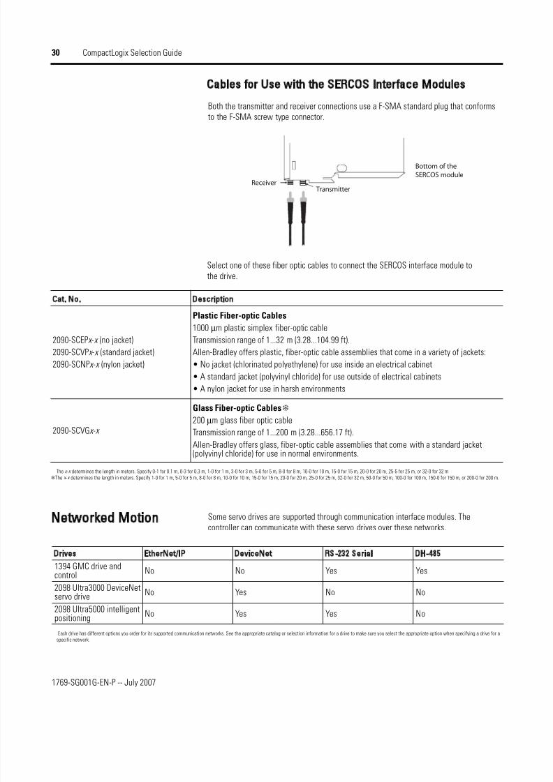
Cables for Use with the SERCOS Interface Modules
Both the transmitter and receiver connections use a F-SMA standard plug that conforms
to the F-SMA screw type connector.
Receiver Transmitter
Bottom of the
SERCOS module
Select one of these fiber optic cables to connect the SERCOS interface module to
the drive.
Cat. No. Description
2090-SCEPx -x (no jacket)
2090-SCVPx -x (standard jacket)
2090-SCNPx -x (nylon jacket)
Plastic Fiber-optic Cables
1000 μm plastic simplex fiber-optic cable
Transmission range of 1...32 m (3.28...104.99 ft).
Allen-Bradley offers plastic, fiber-optic cable assemblies that come in a variety of jackets:
• No jacket (chlorinated polyethylene) for use inside an electrical cabinet
• A standard jacket (polyvinyl chloride) for use outside of electrical cabinets
• A nylon jacket for use in harsh environments
2090-SCVGx -x
Glass Fiber-optic Cables
200 μm glass fiber optic cable
Transmission range of 1...200 m (3.28...656.17 ft).
Allen-Bradley offers glass, fiber-optic cable assemblies that come with a standard jacket(polyvinyl chloride) for use in normal environments.
The x -x determines the length in meters. Specify 0-1 for 0.1 m, 0-3 for 0.3 m, 1-0 for 1 m, 3-0 for 3 m, 5-0 for 5 m, 8-0 for 8 m, 10-0 for 10 m, 15-0 for 15 m, 20-0 for 20 m, 25-5 for 25 m, or 32-0 for 32 m.
The x -x determines the length in meters. Specify 1-0 for 1 m, 5-0 for 5 m, 8-0 for 8 m, 10-0 for 10 m, 15-0 for 15 m, 20-0 for 20 m, 25-0 for 25 m, 32-0 for 32 m, 50-0 for 50 m, 100-0 for 100 m, 150-0 for 150 m, or 200-0 for 200 m.

8/6/2019 Compact Logix Selection Guide
http://slidepdf.com/reader/full/compact-logix-selection-guide 31/64
31
1769-SG001G-EN-P -- July 2007
CompactLogix Selection Guide
A 3-axis system with Kinetix drives supports:
execution of 4 axes per 1 ms.
velocity bandwidth > 400 Hz and current loop bandwidth > 1000 Hz.
high resolution, unlimited travel, and absolute feedback features.
two feedback ports per Kinetix drive.
Example Configuration - 3-axis Integrated Motion with Kinetix Servo Drives

8/6/2019 Compact Logix Selection Guide
http://slidepdf.com/reader/full/compact-logix-selection-guide 32/64
32
1769-SG001G-EN-P -- July 2007
CompactLogix Selection Guide
A 4-axis system with Kinetix drives supports:
execution of 4 axes per 1 ms.
velocity bandwidth > 400 Hz and current loop bandwidth > 1000 Hz.
high resolution, unlimited travel, and absolute feedback features.
two feedback ports per Kinetix drive.
optional 2094 Line Interface Module (LIM) as the incoming power source for an entire
control panel.
Example Configuration - 4-axis Integrated Motion with Kinetix Drives and LIM Interface

8/6/2019 Compact Logix Selection Guide
http://slidepdf.com/reader/full/compact-logix-selection-guide 33/64

8/6/2019 Compact Logix Selection Guide
http://slidepdf.com/reader/full/compact-logix-selection-guide 34/64
34
1769-SG001G-EN-P -- July 2007
CompactLogix Selection Guide
1769 Compact Digital ac Output Modules
Cat.
No.
1769-OA8
1769-OA16
Number of
Outputs
VoltageCategory/Type,
Output Voltage Range
Leakage
Current, Off-State Output,
Max
Current per
Output, Max.
Current per
Module, Max.
BackplaneCurrent (mA)
at 5V
Power SupplyDistance
Rating
8 100…240V AC85...265 ac @47...63Hz
2.0 mA at 132V ac✶2.5 mA at 265V ac
0.25 A @ 60 °C (140 °F)0.50 A @ 30 °C (86 °F)
2.0 A @ 60 °C (140 °F)4.0 A @ 30 °C (86 °F)
145 mA 8 modules
16 100…240V AC85...265 ac @47...63Hz
2.0 mA at 132V ac✶2.5 mA at 265V ac
0.25 A @ 60 °C (140 °F)0.50 A @ 30 °C (86 °F)
4.0 A @ 60 °C (140 °F)8.0 A @ 30 °C (86 °F)
225 mA 8 modules
1769 Compact Digital ac Input Modules
Cat.
No.
1769-IA8I
1769-IA16
1769-IM12
Number of
Inputs
Voltage
Category/Type,
Input Voltage Range
Input Delay
Time, ON to
OFF
Current, On-
State Input,
Min.
Current, Off-
State Input,
Max.
Backplane
Current (mA)
at5V
Power Supply
Distance
Rating8 individuallyisolated
100 or 120V ac79...132V ac @47...63Hz
20 ms 5 mA @ 79V ac 2.5 mA 90 mA 8 modules
16 100 or 120V ac79...132V ac @47...63Hz
20 ms 5 mA @ 79V ac 2.5 mA 115 mA 8 modules
12 200 or 240V ac159...265V ac @47...60Hz
20 ms 5 mA @ 159V ac 2.5 mA 100 mA 8 modules
1769 Compact Digital dc Input Modules
✶Recommended Loading Resistor - To limit the effects of leakage current through solid state outputs, a loading resistor can be connected in parallel with your load. For 120V ac operation, use a 15 kΩ, 2W resistor. For 240V acoperation use a 15 kΩ, 5W resistor.
Cat. No.
Number of
Inputs
Voltage
Category/Type,
Input Voltage Range
Input Delay
Time, ON to
OFF
Current, On-
State Input,
Min.
Current, Off-
State Input,
Max.
Backplane
Current (mA)
at 5V
Power Supply
Distance
Rating
1769-IG16 16 5V dc, TTL input 4.5...5.5V dc 0.5 ms 1.5 mA off-state✶ 0.6 mA on-state✶ 120 mA 8 modules
1769-IQ6XOW4 624V dc, sinking orsourcing
10...30V dc @ 30 °C(86 °F)10...26.4V dc @ 60°C (140 °F)
8 ms 2 mA 1.5 mA 105 mA 8 modules
1769-IQ16 1624V dc, sinking orsourcing
10...30V dc @ 30 °C(86 °F)10...26.4V dc @ 60°C (140 °F)
8 ms 2 mA 1.5 mA 115 mA 8 modules
1769-IQ16F 16 h igh-speed24V dc, sinking orsourcing
10...30V dc @ 30 °C(86 °F)10...26.4V dc @ 60°C (140 °F)
1 ms 2 mA 1.5 mA 110 mA 8 modules
1769-IQ32 3224V dc, sinking orsourcing
10...30V dc @ 30 °C(86 °F)10...26.4V dc @ 60°C (140 °F)
8 ms 2 mA 1.5 mA 170 mA 8 modules
1769-IQ32T 32 terminated24V dc, sinking orsourcing
20.4...26.4V dc 8 ms 3 mA 1.7 mA 170 mA 8 modules
TTL inputs are inverted (0.2…0.8V dc = logic low voltage = ON-state; 2.0…5.5V dc = logic high voltage = OFF-st ate).

8/6/2019 Compact Logix Selection Guide
http://slidepdf.com/reader/full/compact-logix-selection-guide 35/64
1769 Compact Digital dc Output Modules
Cat. No.
Number of
Outputs
VoltageCategory/Type,
Output
Voltage
Range
Leakage
Current, Off-State Output,
Max
Current per
Output, Max.
Current per
Module, Max.
BackplaneCurrent (mA)
at 5V
Power SupplyDistance
Rating
1769-OB8 8 24V dc, sourcing 20.4...26.4V dc 1.0 mA @ 26.4V dc 2.0 A @ 60 °C (140 °F) 8.0 A @ 60 °C (140 °F) 145 mA 8 modules
1769-OB16 16 24V dc, sourcing 20.4...26.4V dc 1.0 mA @ 26.4V dc0.5 A @ 60 °C (140 °F)1.0 A @ 30 °C (86 °F)
4.0 A @ 60 °C (140 °F)8.0 A @ 30 °C (86 °F)
200 mA 8 modules
1769-OB16P 16 protected 24V dc, sourcing 20.4...26.4V dc 1.0 mA @ 26.4V dc0.5 A @ 60 °C (140 °F)1.0 A @ 30 °C (86 °F)
4.0 A @ 60 °C (140 °F)8.0 A @ 30 °C (86 °F)
160 mA 8 modules
1769-OB32 32 24V dc, sourcing 20.4...26.4V dc 1.0 mA @ 26.4V dc0.5 A @ 60 °C (140 °F)1.0 A @ 30 °C (86 °F)
8.0 A @ 60 °C (140 °F)16.0 A @ 30 °C (86 °F)
300 mA 6 modules
1769-OB32T 32 terminated 24V dc, sourcing 10.2.. .26.4V dc 0.1 mA @ 26.4V dc0.5 A @ 60 °C (140 °F)1.0 A @ 30 °C (86 °F)
4.0 A @ 60 °C (140 °F)8.0 A @ 30 °C (86 °F)
220 mA 8 modules
1769-OG16 16 5V dc, TTL output 4.5...5.5V dc ⎯ 0.24 A @ 60 °C (140 °F) 0.38 A @ 60 °C (140 °F) 200 mA 8 modules
1769-OV16 16 24V DC, sinking 20.4...26.4V dc 1.0 mA @ 26.4V dc0.5 A @ 60 °C (140 °F)1.0 A @ 30 °C (86 °F)
4.0 A @ 60 °C (140 °F)8.0 A @ 30 °C (86 °F)
200 mA 8 modules
1769-OV32T 32 terminated 24V dc, sinking 10.2...26.4V dc 1.0 mA @ 26.4V dc0.5 A @ 60 °C (140 °F)1.0 A @ 30 °C (86 °F)
4.0 A @ 60 °C (140 °F)8.0 A @ 30 °C (86 °F)
220 mA 8 modules
35
1769-SG001G-EN-P -- July 2007
CompactLogix Selection Guide

8/6/2019 Compact Logix Selection Guide
http://slidepdf.com/reader/full/compact-logix-selection-guide 36/64
36
1769-SG001G-EN-P -- July 2007
CompactLogix Selection Guide
Relay Contact Ratings
These ratings apply to the digital contact output modules.
Volts,
Max.
240V ac
120V ac
125V dc
24V dc
Continuous Amps
per Point
Amperes Voltamperes
IEC 947 NEMA ICS 2-125ake Break Make Break
2.5 A7.5 A 0.75 A
1800 VA 180 VA AC15✶ C30015 A 1.5 A
1.0 A 0.22 A 28 VA DC13✶ R150
2.0 A 1.2 A 28 VA ⎯ ⎯
✶Does not apply to the 1769-OW16 module.
1769 Compact Digital Contact Output Modules
Cat. No.
1769-IQ6XOW4
1769-OW8
1769-OW8I
1769-OW16
Number of
Outputs
Voltage
Category/Ty
pe, Output
Voltage
Range
Leakage
Current, Off-
State
Output,Max
Current per
Output, Max.
Current per
Module,
Max.
Backplane
Current (mA)
at 5V
Backplane
Current (mA)
at 24V
Power
Supply
Distance
Rating
4 24V dc5...265V ac5...125V dc
0 mA 2.5 A 8.0 A 105 mA 50 mA 8 modules
8 24V dc5...265V ac5...125V dc
0 mA0.5 A @ 60 °C (140 °F)1.0 A @ 30 °C (86 °F)
16 A 125 mA 100 mA 8 modules
8 individuallyisolated
24V dc5...265V ac5...125V dc
0 mA0.5 A @ 60 °C (140 °F)1.0 A @ 30 °C (86 °F)
16 A 125 mA 100 mA 8 modules
16 24V dc5...265V ac5...125V dc
0 mA 2.5 A 20 A 205 mA 180 mA 8 modules
Analog I/O Modules Individually configurable channels
On-board scaling
Autocalibration of inputs
Selectable input filters
Over-range and under-range detection and indication
Input modules offer both single-ended or differential inputs
High accuracy rating
Choose from a wide variety of analog, thermocouple, and RTS modules. Features include:

8/6/2019 Compact Logix Selection Guide
http://slidepdf.com/reader/full/compact-logix-selection-guide 37/64
1769 Compact Analog Modules
Cat. No.
1769-IF4
1769-IF4I
1769-IF8
1769-OF2
1769-OF4CI
1769-OF4VI
1769-OF8C
1769-OF8V
1769-IF4XOF2
1769-IR6
1769-IT6
Number of
Inputs
Number of
Outputs
Resolution,
Bits Signal Range
Sensors
Supported
Backplane
Current (mA)
at5V
Backplane
Current (mA)
at 24V
Power Supply
Distance
Rating
4 — 14 bits (unipolar)
0…20 mA4…20 mA0…10V dc±10V dc0…5V dc1…5V dc
— 105 mA 60 mA 8 modules
4 individuallyisolated
⎯ 16 bits (unipolar)
±10.5V dc-0.5…10.5V dc-0.5...5.25V dc0.5…5.25V dc
⎯ 145 mA 95 mA 8 modules
8 ⎯ 16 bits (unipolar)
0…20 mA4…20 mA0…10V dc±10V dc0…5V dc1…5V dc
⎯ 120 mA 70 mA 8 modules
— 2 14 bits — — 120 mA 120 mA✶ 8 modules
⎯ 4 current,individuallyisolated
16 bits (unipolar)4…20 mA0…20V mA
⎯ 145 mA 140 mA 8 modules
⎯ 4 voltage,individuallyisolated
16 bits (unipolar)
-10…10V dc0…5V dc0...10V dc1…5V dc
⎯ 145 mA 75 mA 8 modules
⎯ 8 current 16 bits (unipolar)0…20 mA4…20 mA
⎯ 145 mA 160 mA 8 modules
⎯ 8 voltage 16 bits (unipolar)
±10.5V dc-0.5…10.5V dc-0.5...5.25V dc0.5…5.25V dc
⎯ 145 mA 125 mA 8 modules
42 individuallyisolated
8 bits plus signindividually isolated
0…10V dc±10V dc0…5V dc
1…5V dc
— 120 mA 160 mA 8 modules
6 —Input filter andconfigurationdependent
—
100, 200, 500, 1000 ΩPlatinum, alpha=385100, 200, 500, 1000 ΩPlatinum, alpha=3916120 Ω Nickel, alpha=672120 Ω Nickel, alpha=61810 Ω Copper604 Ω Nickel-Iron 5180…150 Ω0…500 Ω0…1000 Ω0…3000 Ω
100 mA 45 mA 8 modules
6, plus 2 coldjunction sensors
— — —
Thermocouple types: J, K,T, E, R, S, B, N, C±50mV±100mV
100 mA 40 mA 8 modules
✶If the optional 24V dc Class 2 power supply is used, the 24V dc current draw from the bus is 0 mA.
Sign is always positive.
37
1769-SG001G-EN-P -- July 2007
CompactLogix Selection Guide

8/6/2019 Compact Logix Selection Guide
http://slidepdf.com/reader/full/compact-logix-selection-guide 38/64
38
1769-SG001G-EN-P -- July 2007
CompactLogix Selection Guide
Specialty I/O Modules Specialty I/O modules are available for more application-specific needs.
1769-HSC High-speed Counter Module
Use the 1769-HSC when you need:
a counter module that is capable of reacting to high-speed input signals.
to generate rate and time-between-pulses (pulse interval) data.
as many as 2 channels of quadrature or 4 channels of pulse/count inputs.
1769-ARM Address Reserve Module
Use a 1769-ARM address reserve module to reserve module slots. After creating an I/O
configuration and user program, you can remove and replace any I/O module in the system
with a 1769-ARM module once you inhibit the removed module in RSLogix 5000
programming software.
1769-BOOLEAN Control Module
Use the 1769-BOOLEAN module in applications that require repeatability, such as material
handling and packaging, when there is a requirement to activate an output based on an
input’s transition. If the Boolean expression is true, the output is directed to the ON state.
If the Boolean expression is false, the output channel is directed to the OFF state. There
are four operators that you can configure as OR, AND, XOR, or none.
Cat. No. Number of Inputs Number of Outputs
Voltage Category/Type,
Input
Backplane Current (mA)
at 5V
Power Supply Distance
Rating
1769-BOOLEAN8 real8 virtual
424V dc, sinking input, sourcingoutput
220 mA 8 modules
Cat.
No. Number of Inputs Number of Outputs
Backplane Current (mA)
at 5V External Power
Power Supply Distance
Rating
1769-HSC 2 4 425 mA19.2...31.2V dc100 mA @ 24V dc
4 modules
Cat. No. Number of Inputs Number of Outputs Backplane Current (mA) at 5V
1769-ARM
Power Supply Distance Rating
— — 60 mA 8 modules
1769-ASCII Serial Gateway Module
The 1769-ASCII module, a general purpose two-channel ASCII interface, provides a
flexible network interface to a wide variety of RS-232, RS-485, and RS-422 ASCII devices.
The module provides the communication connections to the ASCII device.
Cat. No. Channel Configuration Message Length, Max. Backplane Current (mA) at 5V Power Supply Distance Rating
1769-ASCII RS-232, RS-422, or RS-485 200 characters 500 mA 4 modules

8/6/2019 Compact Logix Selection Guide
http://slidepdf.com/reader/full/compact-logix-selection-guide 39/64
1492 Wiring Systems As an alternative to buying RTBs and connecting the wires yourself, you can buy a wiringsystem of:
interface modules (IFMs) that provide the output terminal blocks for digital I/O modules.
Use the pre-wired cables that match the I/O module to the IFM.
analog interface modules (AIFMs) that provide the output terminal blocks for analog I/O
modules. Use the pre-wired cables that match the I/O module to the AIFM.
I/O module-ready cables. One end of the cable assembly is an RTB that plugs into the
front of the I/O module. The other end has individually color-coded conductors that
connect to a standard terminal block.
1667 PanelConnectModules for Connecting
Sensors
A PanelConnect module and its sensor connection system connect sensors directly to I/O
modules using convenient pre-built cables and connectors.
The PanelConnect module mounts on the enclosure and creates the correct seal for the
entry of the sensor connections. You do not need to seal the opening where the sensorcables enter the enclosure, create custom connectors, or wire to those custom connectors.
Compact I/O to PowerFlex Drives
Cat.
No.
1769-SM1
1769-SM2
Description Communication Rate
Backplane Current
(mA) at 5V
Backplane Current
(mA) at 24V
Power Supply Distance
Rating
Compact I/O to DPI/SCANport Moduleconnects to PowerFlex 7-class drives, other DPI-based host devices, and SCANport-based hostdevices such as 1305 and 1336 PLUS II drives.
DPI: 1925 Kbps or 250 KbpsSCANport: 125 Kbps
280 mA60 mA per channel suppliedby the DPI/SCANport host
6 modules
Compact I/O to DSI/Modbus Moduleconnects to PowerFlex 4-class drives and toother Modbus RTU slave devices, such asPowerFlex 7-class drives with 20-COMM-HRS485 HVAC adapters.
DSI: 19.2 KbpsModbus RTU: 300...38.4 Kbps
350 mA 0 mA 4 modules
39
1769-SG001G-EN-P -- July 2007
CompactLogix Selection Guide
The 1769-SMx modules provide a Compact I/O connection to PowerFlex drives.

8/6/2019 Compact Logix Selection Guide
http://slidepdf.com/reader/full/compact-logix-selection-guide 40/64
40
1769-SG001G-EN-P -- July 2007
CompactLogix Selection Guide
Place Compact I/OModules in aCompactLogix System
You can DIN-rail or panel mount the controller and I/O modules. The number of local I/O
modules supported depends on the controller.
Each 1769 I/O module has a distance rating. In 1769 systems, the distance rating is the
number of modules between the specific module and the 1769 power supply. In a 1768
system, the distance rating is the number of modules between the specific I/O module
and the 1768 controller.
Expansion Cables
If you divide 1769 modules into multiple banks, make sure:
each bank needs its own power supply.
use expansion cables to connect the banks.
the last I/O bank requires an end cap.
This Controller Supports That can be in Considerations
1769-L35CR
1769-L35E30 local modules 3 separate banks Each module uses a set amount of backplane memory, in addition
to the data that the module stores or transfers.
The additional banks are powered by standard 1769 power suppliesand connect to the main rack by using standard 1769 expansioncables.
1769-L32C
1769-L32E
1769-L31
16 local modules 3 separate banks
1768-L43 16 local modules 3 separate banksAs many as eight 1769 local modules can be attached to the 1768backplane. The remaining modules can be in one or two additionalI/O banks.
The additional banks are powered by standard 1769 power suppliesand connect to the main rack by using standard 1769 expansioncables.
1768-L45 30 local modules 3 separate banks
The final I/O bank in the CompactLogix system needs an end cap on the end without the
expansion cable.
For a Order
Right end cap 1769-ECR
Left end cap 1769-ECL
End Caps
How you orient I/O banks determines which expansion cables you need to connect the
I/O banks.
If you add a And connect the chassis Use this cableς
Second bankRight to left 1769-CRLx
Right to right 1769-CRRx
Third bank
Right to left 1769-CRLx
Right to right 1769CRRx
Left to left 1769-CLLx
ς Where x = 1 for 1 ft (305 mm) or 3 for 3.28 ft (1 m).

8/6/2019 Compact Logix Selection Guide
http://slidepdf.com/reader/full/compact-logix-selection-guide 41/64
8/6/2019 Compact Logix Selection Guide
http://slidepdf.com/reader/full/compact-logix-selection-guide 42/64
42
1769-SG001G-EN-P -- July 2007
CompactLogix Selection Guide
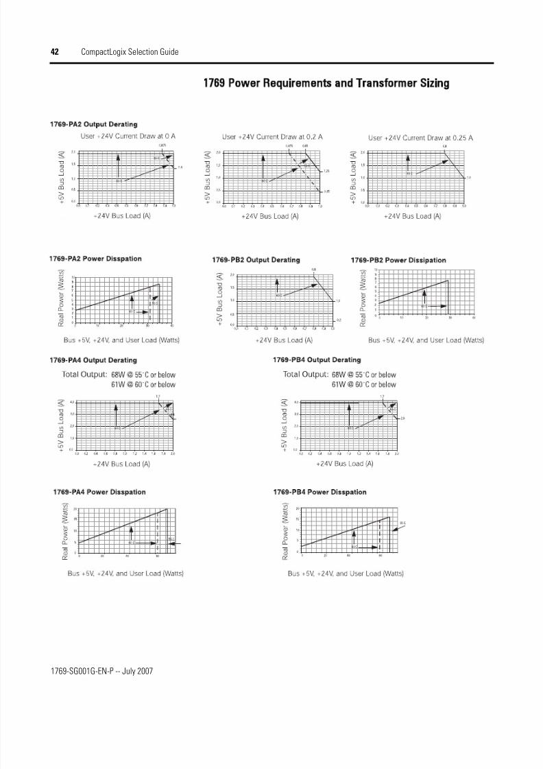
1769 Power Requirements and Transformer Sizing
8/6/2019 Compact Logix Selection Guide
http://slidepdf.com/reader/full/compact-logix-selection-guide 43/64

8/6/2019 Compact Logix Selection Guide
http://slidepdf.com/reader/full/compact-logix-selection-guide 44/64
44
1769-SG001G-EN-P -- July 2007
CompactLogix Selection Guide
1768 Power Requirements and Transformer Sizing

8/6/2019 Compact Logix Selection Guide
http://slidepdf.com/reader/full/compact-logix-selection-guide 45/64
45
1769-SG001G-EN-P -- July 2007
CompactLogix Selection Guide
Step 6 - Select: Mounting Panel mount or DIN rail mount
Appropriate number of panels or DIN
rails based on the number of modules
and the physical location
One end cap per controller system You can panel mount or DIN-rail mount a CompactLogix system. The CompactLogix system
must be mounted so that the modules are horizontal to each other.
If you decide to use a DIN rail, use steel, 35 x 7.55mm DIN rails (A-B part number 199-
DR1; 46277-3; EN 50022). The DIN rails for all CompactLogix system components must be
mounted on a common, conductive surface to be sure of proper electromagnetic
interference (EMI) performance.
Ground a CompactLogix system through the:
non-coated, steel DIN rail.
panel-mount screw hole containing the ground strap.
1769 CompactLogixDimensions
1769-L3x Minimum Spacing Requirements

8/6/2019 Compact Logix Selection Guide
http://slidepdf.com/reader/full/compact-logix-selection-guide 46/64
46
1769-SG001G-EN-P -- July 2007
CompactLogix Selection Guide
Single 1769 Slot Dimensions
One-and-a-half 1769 Slot Dimensions

8/6/2019 Compact Logix Selection Guide
http://slidepdf.com/reader/full/compact-logix-selection-guide 47/64
47
1769-SG001G-EN-P -- July 2007
CompactLogix Selection Guide
1769 CompactLogix Dimensions
1769 Power Supply Dimensions

8/6/2019 Compact Logix Selection Guide
http://slidepdf.com/reader/full/compact-logix-selection-guide 48/64

8/6/2019 Compact Logix Selection Guide
http://slidepdf.com/reader/full/compact-logix-selection-guide 49/64
49
1769-SG001G-EN-P -- July 2007
CompactLogix Selection Guide
Single 1768 Slot Dimensions
1768 CompactLogix Dimensions

8/6/2019 Compact Logix Selection Guide
http://slidepdf.com/reader/full/compact-logix-selection-guide 50/64
50
1769-SG001G-EN-P -- July 2007
CompactLogix Selection Guide
1768 Power Supply Dimensions

8/6/2019 Compact Logix Selection Guide
http://slidepdf.com/reader/full/compact-logix-selection-guide 51/64

8/6/2019 Compact Logix Selection Guide
http://slidepdf.com/reader/full/compact-logix-selection-guide 52/64
52
1769-SG001G-EN-P -- July 2007
CompactLogix Selection Guide
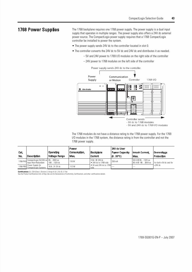
PanelView Plus Terminal The PanelView Plus terminal is ideal for applications that need to monitor, control, and
display information graphically, allowing operators to quickly understand the status of
their application. PanelView Plus terminals come with RSView Studio software and have
embedded RSView Machine Edition software functionality. PanelView Plus terminals
combine the best features from the popular Allen-Bradley PanelView Standard and
PanelView e operator-interface products and adds new functionality.
Multi-vendor communication
Trending
Expressions
Data logging
Animation
RSView Studio software direct browsing of RSLogix 5000 addresses
VersaView IndustrialComputers and Monitors
VersaView products are a family of industrial computer and monitor solutions, comprised
of integrated display computers, workstations, non-display computers, and flat panel
monitors. VersaView products offer effortless management of changing technology, a
rugged but cost-effective design, and easier product configuration. All VersaView products
provide the latest industrial solution available, optimized for visualization, control,
information processing, and maintenance application.
PanelView Plus CETerminal
PanelView Plus CE products offer open Windows CE terminals in Windows desktopenvironments, bringing together features of operator interfaces and industrial computers.
It is a high performance computer with a CompactFlash drive and integrated RSView
Machine Edition runtime (no activation required). There’s no hard disk, no fan, and no
moving parts, which means maximum reliability on the plant floor. Easy to set up and
maintain, PanelView Plus CE products provide an open system that’s rugged and
economical, offering high functionality in an easy to use package.

8/6/2019 Compact Logix Selection Guide
http://slidepdf.com/reader/full/compact-logix-selection-guide 53/64

8/6/2019 Compact Logix Selection Guide
http://slidepdf.com/reader/full/compact-logix-selection-guide 54/64
54
1769-SG001G-EN-P -- July 2007
CompactLogix Selection Guide
Programming Software
RSLogix 5000 Enterprise Series Software Requirements
Description Value
Personal computerPentium II 450 MHz minPentium III 733 MHz (or better) recommended
Software requirements
Supported operating systems:• Microsoft Windows XP Professional version 2002 (with Service Pack 1 or 2) or XP Home version 2002• Microsoft Windows 2000 Professional with Service Pack 1, 2, or 3• Microsoft Windows Server 2003
RAM128 MB of RAM min256 MB of RAM recommended
Hard disk space 100 MB of free hard disk space (or more based on application requirements)
Video requirements256-color VGA graphics adapter800 x 600 min resolution (True Color 1024 x 768 recommended)
RSLogix 5000 Enterprise Series software is designed to work with Logix5000 controller
platforms. RSLogix 5000 Enterprise Series software is an IEC 61131-3 compliant
software package that offers relay ladder, structured text, function block diagram, and
sequential function chart editors for you to develop application programs. Create your
own instructions by encapsulating a section of logic in any programming language into
an add-on instruction.
RSLogix 5000 Enterprise Series software also includes axis configuration and
programming support for motion control. With RSLogix 5000 Enterprise Series software,
you need only one software package for sequential, process, drive, motion control, and
safety programming.

8/6/2019 Compact Logix Selection Guide
http://slidepdf.com/reader/full/compact-logix-selection-guide 55/64
55
1769-SG001G-EN-P -- July 2007
CompactLogix Selection Guide
Select the RSLogix 5000 Enterprise Series Software Package
Available Features
Service
Edition 9324-
RLD000xxE ♠
Mini Edition
9324-
RLD200xxE
Lite Edition
9324-
RLD250xxE
Standard
Edition 9324-
RLD300xxE
Standard/
NetWorxEdition 9324-
RLD300NXxxE
Full Edition:
Node Locked
9324-
RLD600xxEConcurrent
License 9324-
RLD600xxF
ProfessionalEdition 9324-
RLD700NXxxE
Logix5000 controllers supported All♠CompactLogixFlexLogix
CompactLogixFlexLogix
All All All‡ All
Relay ladder diagram editor§Upload/downloadand view
Full support Full support Full support Full support Full support Full support
Function block diagram editor9324-RLDFBDENE
Upload/downloadand view
Upload/downloadand view
Full supportUpload/downloadand view
Upload/downloadand view
Full support Full support
Sequential function chart editor9324-RLDSFCE
Upload/downloadand view
Upload/downloadand view
Full supportUpload/downloadand view
Upload/downloadand view
Full support Full support
Structured text editor9324-RLDSTXE
Upload/downloadand view
Upload/downloadand view
Full supportUpload/downloadand view
Upload/downloadand view
Full support Full support
PhaseManager9324-RLDPME
Upload/download Upload/download Upload/download Upload/download Upload/download Included Included
GuardLogix Safety9324-RLDGLXE
Upload/downloadand view
NA NAUpload/downloadand view
Upload/downloadand view
Included Included
Highly integrated motionUpload/downloadand view
Upload/download Full support Full support Full support Full support Full support
Graphical trending Full support Full support Full support Full support Full support Full support Full support
DriveExecutive Lite9303-4DTE01ENE
Available separately Available separately Available separately Included Included Included Included
PIDE autotune9323-ATUNEENE
Available separately Available separately Available separately Available separately Available separately Included Included
RSMACC audit support Included Included Included Included Included Included Included
FuzzyDesigner9324-RLDFZYENE
NA Avai lable separately Avai lable separate ly Avai lable separately Avai lab le separate ly Avai lable separately Avai lable separately
RSLogix Emulate 50009310-WED200ENE
Available separately NA NA Available separately Available separately Available separately Included
Logix CPU security Included Included Included Included Included Included Included
Routine source protection Included Included Included Included Included Included Included
RSMACC (security server) client Included Included Included Included Included Included Included
Standalone security server Included Included Included Included Included Included Included
RSLinx Classic software Lite included Lite included Lite included Lite included Lite included Lite included OEM included
RSNetWorx for ControlNet softwareRSNetWorx for DeviceNet softwareRSNetWorx for EtherNet/IP software
Available separately Available separately Available separately Available separately Included Available separately Included
RSLogix Architect9326-LGXARCHENE
Available separately Available separately Available separately Available separately Available separately Available separately Included
FBD ActiveX faceplates Included Included Included Included Included Included Included
Tag data upload/download Included Included Included Included Included Included Included
RSLogix 5000 project compare Included Included Included Included Included Included Included
Tag custom data monitor Included Included Included Included Included Included Included
RSView demo (50 tags/2 hours) Available separately Available separately Available separately Available separately Available separately Available separately Included
Upgrades
To Standard: 9324-RLD0U3xx ETo Full: 9324-RLD0U6xx ETo Professional:9324-RLD0U7xx E
To Standard: 9324-RLD2U3xx ETo Professional:9324-RLD2U7xx E
To Full: 9324-RLD25U6xx ETo Professional:9324-RLD25U7xx E
To Full: Multi-language pack
NA
Node Locked toConcurrent License:9324-RLD6U6Fxx UTo Professional:9324-RLD6U7xx E
NA
Replace xx in the catalog number with the appropriate language designation: ZH=Chinese, EN=English, FR=French, DE=German, IT=Italian, JP=Japanese, KO=Korean, PT=Portuguese, and ES=Spanish.♠Service Edition supports controllers running firmware revision 12 and later.‡Full Edition supports controllers running firmware revision 10 and later.§A multiple language editor package is available as 9324-RLDMLPE. It contains the function block, sequential function chart, and structured text editors.RSNetWorx for ControlNet software is 9357-CNETL3. RSNetWorx for DeviceNet software is 9357-DNETL3. RSNetWorx for EtherNet/IP software is 9357-ENETL3. They are available together as 9357-ANETL3.
The multiple language editor package (9324-RLDMLPE) is not the same as an upgrade, but it extends the programming languages to match those in a Full package.As of RSLogix 5000 programming software, version 15.
As of RSLogix 5000 programming software, version 16.
8/6/2019 Compact Logix Selection Guide
http://slidepdf.com/reader/full/compact-logix-selection-guide 56/64
56
1769-SG001G-EN-P -- July 2007
CompactLogix Selection Guide
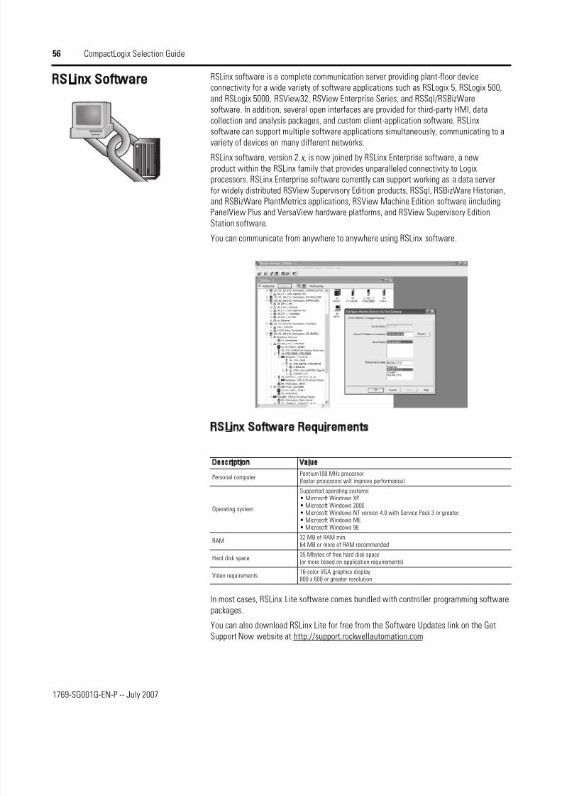
RSLinx Software RSLinx software is a complete communication server providing plant-floor device
connectivity for a wide variety of software applications such as RSLogix 5, RSLogix 500,
and RSLogix 5000, RSView32, RSView Enterprise Series, and RSSql/RSBizWare
software. In addition, several open interfaces are provided for third-party HMI, data
collection and analysis packages, and custom client-application software. RSLinx
software can support multiple software applications simultaneously, communicating to a
variety of devices on many different networks.
RSLinx software, version 2.x , is now joined by RSLinx Enterprise software, a new
product within the RSLinx family that provides unparalleled connectivity to Logix
processors. RSLinx Enterprise software currently can support working as a data server
for widely distributed RSView Supervisory Edition products, RSSql, RSBizWare Historian,
and RSBizWare PlantMetrics applications, RSView Machine Edition software iincluding
PanelView Plus and VersaView hardware platforms, and RSView Supervisory Edition
Station software.
You can communicate from anywhere to anywhere using RSLinx software.
RSLinx Software Requirements
Description Value
Personal computerPentium100 MHz processor(faster processors will improve performance)
Operating system
Supported operating systems:• Microsoft Windows XP• Microsoft Windows 2000• Microsoft Windows NT version 4.0 with Service Pack 3 or greater• Microsoft Windows ME• Microsoft Windows 98
RAM32 MB of RAM min64 MB or more of RAM recommended
Hard disk space35 Mbytes of free hard disk space(or more based on application requirements)
Video requirements16-color VGA graphics display800 x 600 or greater resolution
In most cases, RSLinx Lite software comes bundled with controller programming software
packages.
You can also download RSLinx Lite for free from the Software Updates link on the Get
Support Now website at http://support.rockwellautomation.com

8/6/2019 Compact Logix Selection Guide
http://slidepdf.com/reader/full/compact-logix-selection-guide 57/64
57
1769-SG001G-EN-P -- July 2007
CompactLogix Selection Guide
Select the RSLinx Software Package
Cat. No. RSLinx Products
Available only bundled with other productssuch as RSLogix software products.
RSLinx Lite
9355-WABSNENE RSLinx Single Node
9355-WABOEMENE RSLinx OEM
9355-WABENE RSLinx Professional
9355-WABGWENE RSLinx Gateway
9355-WABCENE RSLinx SDK
9355-RSLETENE RSLinx Enterprise

8/6/2019 Compact Logix Selection Guide
http://slidepdf.com/reader/full/compact-logix-selection-guide 58/64
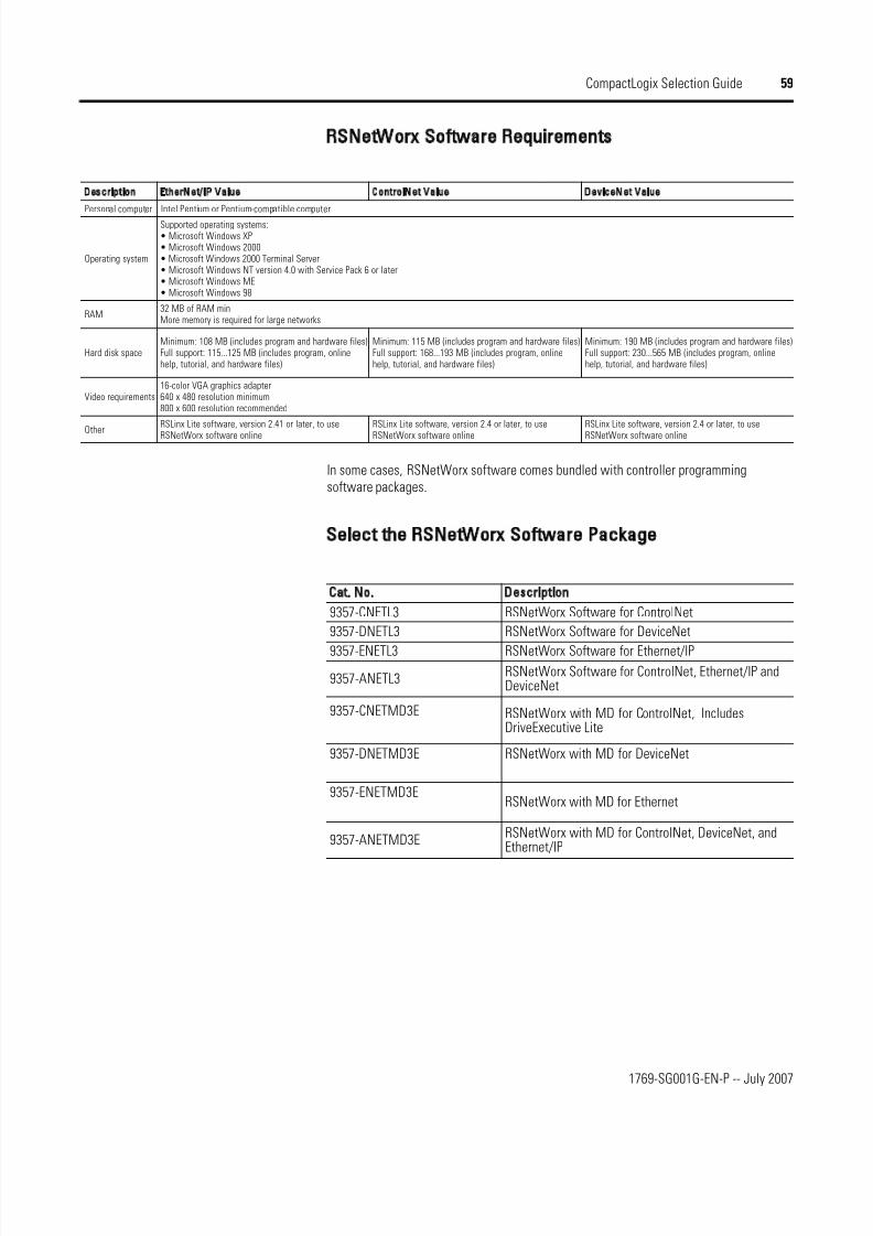
8/6/2019 Compact Logix Selection Guide
http://slidepdf.com/reader/full/compact-logix-selection-guide 59/64
59
1769-SG001G-EN-P -- July 2007
CompactLogix Selection Guide
RSNetWorx Software Requirements
In some cases, RSNetWorx software comes bundled with controller programming
software packages.
Select the RSNetWorx Software Package
Cat. No. Description
9357-CNETL3 RSNetWorx Software for ControlNet
9357-DNETL3 RSNetWorx Software for DeviceNet
9357-ENETL3 RSNetWorx Software for Ethernet/IP
9357-ANETL3RSNetWorx Software for ControlNet, Ethernet/IP andDeviceNet
9357-CNETMD3E RSNetWorx with MD for ControlNet, IncludesDriveExecutive Lite
9357-DNETMD3E RSNetWorx with MD for DeviceNet
9357-ENETMD3ERSNetWorx with MD for Ethernet
9357-ANETMD3ERSNetWorx with MD for ControlNet, DeviceNet, andEthernet/IP
Description EtherNet/IP Value ControlNet Value DeviceNet Value
Personal computer Intel Pentium or Pentium-compatible computer
Operating system
Supported operating systems:• Microsoft Windows XP• Microsoft Windows 2000• Microsoft Windows 2000 Terminal Server• Microsoft Windows NT version 4.0 with Service Pack 6 or later• Microsoft Windows ME• Microsoft Windows 98
RAM32 MB of RAM minMore memory is required for large networks
Hard disk spaceMinimum: 108 MB (includes program and hardware files)Full support: 115...125 MB (includes program, onlinehelp, tutorial, and hardware files)
Minimum: 115 MB (includes program and hardware files)Full support: 168...193 MB (includes program, onlinehelp, tutorial, and hardware files)
Minimum: 190 MB (includes program and hardware files)Full support: 230...565 MB (includes program, onlinehelp, tutorial, and hardware files)
Video requirements16-color VGA graphics adapter640 x 480 resolution minimum800 x 600 resolution recommended
Other
RSLinx Lite software, version 2.41 or later, to use
RSNetWorx software online
RSLinx Lite software, version 2.4 or later, to use
RSNetWorx software online
RSLinx Lite software, version 2.4 or later, to use
RSNetWorx software online

8/6/2019 Compact Logix Selection Guide
http://slidepdf.com/reader/full/compact-logix-selection-guide 60/64
60
1769-SG001G-EN-P -- July 2007
CompactLogix Selection Guide
RSLogix Emulate 5000Software
RSLogix Emulate 5000 software (9310-WED200ENE) is the emulation package for the
Logix5000 controllers. RSLogix Emulate 5000 software, used in conjunction with RSLogix
5000 software, lets you run and debug your application code while at your computer. In
addition, RSLogix Emulate 5000 software lets you test HMI screens, developed in RSView
software for example, without the need to connect to a real controller.
You can set tracepoint and breakpoint instructions (ladder diagram only) in your
application code, use traces, and also vary the execution speed of the emulator. RSLogix
Emulate 5000 software supports all the programming languages (ladder diagram, function
block diagram, structured text, and sequential function chart). RSLogix Emulate 5000
software does not allow for control of real I/O.
Use RSLogix Emulate software for:
RSLogix Emulate 5000 Requirements
Description Value
Personal computerIBM-compatible Intel Pentium II 300 MHz or Celeron 300A(Pentium III 600 MHz recommended)
Operating system
Supported operating systems:• Microsoft Windows XP with Service Pack 1or greater• Microsoft Windows 2000 with Service Pack 2 or greater• Microsoft Windows NT version 4.0 with Service Pack 6A or greater
RAM 128 MB of RAM min
Hard disk space 50 MB of free hard disk space
Video requirements16-color VGA graphics display800 x 600 or greater resolution
RSLogix Emulate 5000 software includes RSTestStand Lite software. RSTestStand Lite
software lets you create virtual operator consoles that can help test your application code.
RSTestStand Lite software can be upgraded to the standard version by ordering catalog
number 9310-TSTNDENE.
RSLogix Emulate 5000 and RSTestStand Lite software are included with RSLogix 5000
Professional software.
troubleshooting.
Stop the process whenever a selected rung goes true, effectively freezing the process at
the instant that any error occurs.
ladder logic scanning options.
Scan your ladder logic continuously, one program scan at a time, rung-by-rung, or select
a specific block of rungs to emulate. Selecting a block of rungs lets you isolate aparticular section of the program for testing purposes. You can also set trace points to
trace application program tags and set break points to halt program execution at
predetermined locations.

8/6/2019 Compact Logix Selection Guide
http://slidepdf.com/reader/full/compact-logix-selection-guide 61/64
Notes

8/6/2019 Compact Logix Selection Guide
http://slidepdf.com/reader/full/compact-logix-selection-guide 62/64
Notes

8/6/2019 Compact Logix Selection Guide
http://slidepdf.com/reader/full/compact-logix-selection-guide 63/64
Notes

8/6/2019 Compact Logix Selection Guide
http://slidepdf.com/reader/full/compact-logix-selection-guide 64/64