compact dual-band dual-polarized antenna for mimo … · compact dual-band dual-polarized antenna...
TRANSCRIPT

HAL Id: hal-00983477https://hal.archives-ouvertes.fr/hal-00983477
Submitted on 25 Apr 2014
HAL is a multi-disciplinary open accessarchive for the deposit and dissemination of sci-entific research documents, whether they are pub-lished or not. The documents may come fromteaching and research institutions in France orabroad, or from public or private research centers.
L’archive ouverte pluridisciplinaire HAL, estdestinée au dépôt et à la diffusion de documentsscientifiques de niveau recherche, publiés ou non,émanant des établissements d’enseignement et derecherche français ou étrangers, des laboratoirespublics ou privés.
Compact Dual-Band Dual-Polarized Antenna for MIMOLTE Applications
Lila Mouffok, Anne-Claire Lepage, Julien Sarrazin, Xavier Begaud
To cite this version:Lila Mouffok, Anne-Claire Lepage, Julien Sarrazin, Xavier Begaud. Compact Dual-Band Dual-Polarized Antenna for MIMO LTE Applications. International Journal of Antennas and Propagation,Hindawi Publishing Corporation, 2012, 2012, pp.398423. <10.1155/2012/398423>. <hal-00983477>
Hindawi Publishing CorporationInternational Journal of Antennas and PropagationVolume 2012, Article ID 398423, 10 pagesdoi:10.1155/2012/398423
Research Article
Compact Dual-Band Dual-Polarized Antenna forMIMO LTE Applications
Lila Mouffok, Anne Claire Lepage, Julien Sarrazin, and Xavier Begaud
Department Comelec Institut Mines Telecom, Telecom ParisTech, LTCI CNRS UMR 5141, 46 Rue Barrault,75634 Paris Cedex 13, France
Correspondence should be addressed to Lila Mouffok, [email protected]
Received 15 May 2012; Revised 18 July 2012; Accepted 6 September 2012
Academic Editor: Minh-Chau Huynh
Copyright © 2012 Lila Mouffok et al. This is an open access article distributed under the Creative Commons Attribution License,which permits unrestricted use, distribution, and reproduction in any medium, provided the original work is properly cited.
A system of two dual-band dual-polarized antennas is proposed. It operates in two bands, 700 to 862 MHz and 2.5 to 2.69 GHz,thereby making it suitable for LTE applications. The design is composed of two compact orthogonal monopoles printed closeto each other to perform diversity in mobile terminals such as tablets or laptops. For each band, two orthogonal polarizationsare available and an isolation higher than 15 dB is achieved between the two monopoles spaced by λ0/10 (where λ0 the centralwavelength in free space of the lower band). A good agreement is observed between simulated and experimental results. Theantenna diversity capability is highlighted with the calculation of envelope correlation and mean effective gain for several antennas’positions in different environment scenarios.
1. Introduction
Deployment of existing and emerging wireless communica-tion systems require a high-data-rate transmission, in orderto satisfy the needs of multimedia applications on terminals.Multiple Input Multiple Output (MIMO) applications havebeen suggested as an effective way to increase the channelcapacity by exploiting multipath scattering effects.
MIMO technology is present in many recent wirelessstandards, such as Long Term Evolution (LTE), and willbe implemented in mobile devices [1]. Several researchworks have proven the efficiency of two-antenna diversityon mobile terminals [2, 3]. However, when the availablespace is limited, the use of a dual-polarized antenna ismore suitable than two separated antennas [4]. A varietyof dual-polarized antennas have been reported recently inwhich good dual-polarized radiation over a wide bandwidth[5] and high isolation between the feeding ports [6] havebeen achieved. However, these antennas are mainly designedfor single-band operation [7] or for frequencies above800 MHz [8]. Most of the dual-band dual-polarized antennasproposed in literature exploit harmonics frequencies [9]or use techniques to generate additional resonances such
as insertion slot [10]. But generally, it leads to a ratiobetween frequency bands below or equal to 2 and impliesa dependence between the two frequency bands. Today,very few designs are reported for dual-band dual-polarizedoperations for the following bands: 700–862 MHz and 2.5–2.69 GHz. In this paper, we firstly present the design of adual-band antenna which can provide a dual-polarizationfor each band, for LTE devices such as a tablet or a laptop.Then, we introduce an enhanced design in which the lowerbandwidth has been increased and the mutual couplingbetween ports has been reduced in the two bands. Thelower band is extended towards TV White Space (TVWS)band to provide radio-cognitive capabilities to the terminal[11].
Finally, the diversity performances of the proposed dual-band dual-polarized antennas are evaluated through theenvelope correlation (ρe) and the mean effective gain inisotropic, indoor, and outdoor environments.
2. Antenna Design
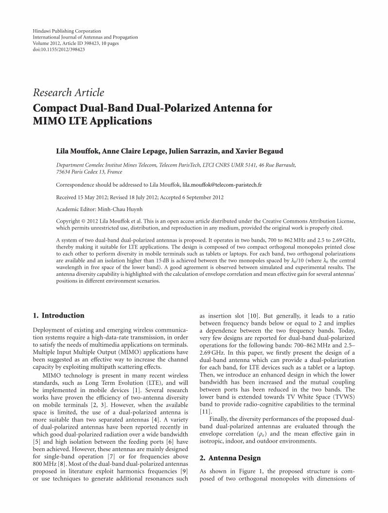
As shown in Figure 1, the proposed structure is com-posed of two orthogonal monopoles with dimensions of
2 International Journal of Antennas and Propagation
Lm
dWm
l
1 2
45◦XY
Z
Via holes
L2L1
(a)
Lgd2
Lgd1
Wgd1
Lgd3
Wgd2
Ls
Ws
Added ground plane
Removed corners
Wgd3
(b)
Figure 1: (a) Front view. (b) Back view of one meander bend ending antennas, with added ground plane and slot.
Lm×Wm = 27.5×1.5 mm2. The two monopoles are identicaland chosen for their omni-directional radiations pattern,enabling them to receive signals whatever their orientation.They are printed on a 140 × 83 mm2 low cost substrate(FR4: εr = 3.8 ± 0.1, tan δ = 0.02, thickness of 0.7 mm).Each monopole is connected to two bend endings: one bendending is a meander line whose length is L1 = 43.3 mmoperating at 790–862 MHz and the small one whose lengthis L2 = 23.5 mm operates at 2.5–2.69 GHz. The distancebetween the two bend endings is l = 14 mm. This designallows to obtain independent frequency bands. The two
monopoles are spaced by d = 36 mm which correspondsto λ01/10 for the lower band and λ02/3 for the higher band,where λ01 is the free-space wavelength of the lower bandcentral frequency ( f01 = 826 MHz) and λ02 the free-spacewavelength of the higher band central frequency ( f02 =2.59 GHz).
The monopoles are fed by two 50 ohms coplanar waveg-uides (CPW), directly etched in the ground plane, as shownin Figure 1(b), in order to distance the connectors andto avoid perturbations on the measured radiation patterns.Each CPW has a line width of 1.8 mm and a gap of 0.33 mm
International Journal of Antennas and Propagation 3
0.7 0.75 0.8 0.85 0.9 0.95 1−30
−25
−20
−15
−10
−5
0
Frequency (GHz)
|S11| without added ground plane|S11| with added ground plane|S21|without added ground plane|S21| with added ground plane
|S ij|
(dB
)
(a)
2 2.2 2.4 2.6 2.8 3−30
−25
−20
−15
−10
−5
0
Frequency (GHz)
|S11| without added ground plane|S11| with added ground plane|S21|without added ground plane|S21| with added ground plane
|S ij|
(dB
)
(b)
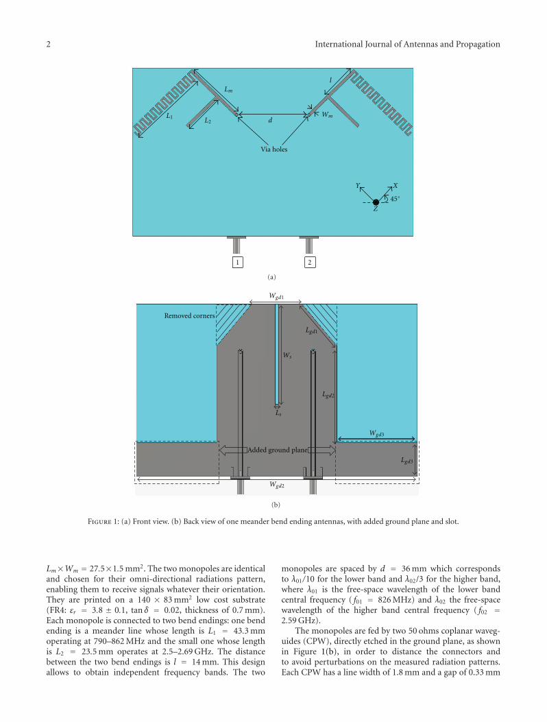
Figure 2: Simulated |Si j| parameters of one meander bend ending antennas without slot, with and without added ground plane: (a) lowerband, (b) higher band.
with the ground plane. Monopoles are connected to CPWthanks to metallic via holes located as the extremity of eachmonopole as shown in Figure 1(a).
2.1. Ground Plane Geometry. Since the small bend ending isclose to the ground plane extremities, it is sensitive to thepath taken by currents along the ground plane. Therefore,a study of the upper part of the ground plane geometryis relevant. It is found that removing corners (shaded partin Figure 1(b)) provides an improvement of higher bandmatching, leading to optimized dimensions Wgd1 = 25 mm,Lgd1 = 25 mm, and Lgd2 = 46 mm.
Coupling between the two antennas occurs via currentsflowing from one antenna to the other one through theground plane. It can be reduced by altering the ground planeto modify currents’ path. Thus, the ground plane is extendedwithout increasing the overall structure size, by adding on thelower part of the substrate, two rectangular shapes on eitherside with dimensions of each one Wgd3 = 40 mm and Lgd3 =17 mm (framed part in Figure 1(b)). Simulations have beenperformed with Transient Solver of CST Microwave Studio.Figure 2 shows a comparison between |Si j| parameters fordesigns without slot, with and without added ground planein each band. Because of the structure’s symmetry, only |S11|and |S21| are plotted. The matching bandwidth criterion istaken for a return loss less than −10 dB. With added groundplane, a shift of the lower band towards lower frequencies(from 0.9 to 0.85 GHz) is observed in Figure 2(a) withoutincreasing the structure size. The bandwidths of the structure
without added ground plane are: 837–957 MHz (13.4%),2.35–2.86 GHz (19.6%), and for the structure with addedground plane are: 796–914 MHz (13.8%), 2.38–2.78 GHz(15.5%). Regarding the isolation, it is largely reduced thanksto the added ground plane: |S21| becomes below −20 dB inthe lower band. Indeed, a resonance has been introduced atthe frequency where coupling occurs. However, the couplingremains high (|S21| < −7 dB) in the higher band as shown inFigure 2(b).
To improve isolation between ports in the higher band,a slot is etched in the ground plane while keeping the samedistance between ports (d), as shown in Figure 1(a). Theintroduction of the slot produces an open circuit which stopsthe circulation of current from one radiating element tothe other one [12]. The optimized structure has a lengthLs = 34 mm and a width Ws = 1.4 mm. Figure 3 shows acomparison of simulated |Si j| parameters of one meanderbend ending antennas with added ground plane, with andwithout slot in the higher band. The introduction of the slotachieves an isolation improvement of 10 dB in the higherband, while it has no effect in the lower band. The bandwidthis slightly reduced but still covers the desired band. Thus,optimization of the two degrees of freedom which arethe slot dimensions and rectangular shapes ground planedimensions leads to a high isolation in the two frequencybands.
2.2. Radiating Element. In order to increase the bandwidth ofthe lower band towards the TVWS band, two bend endings

4 International Journal of Antennas and Propagation
|S11| without slot
|S11| with slot|S21| without slot|S21| with slot
2 2.2 2.4 2.6 2.8 3−30
−25
−20
−15
−10
−5
0
Frequency (GHz)
|S ij|
(dB
)
Figure 3: Simulated |Si j| parameters of one meander bend endingantennas with added ground plane, with and without slot in thehigher band.
are added below the initial meander line to provide addi-tional resonances close to each other. These two meanders areout of sync to provide a single wide band. Moreover, the threelines are connected to each other to extend the bandwidthtowards lower frequencies. After optimization with TransientSolver of CST Microwave Studio, the distance between eachmeander is s = 7 mm as shown in Figure 5 and the overallsize of three bend endings antennas with added ground planeand slot becomes 150 × 90 mm2.
Figure 4 shows the comparison between S-parameters ofone and three bend endings antennas with added groundplane and slot. Matching bandwidth criterion is taken for|S11| < −10 dB. It is seen that the bandwidth is enhancedtowards lower frequencies. Indeed, the relative bandwidth forthe structure with one bend ending is 9.8% (786–867 MHz)and 21.9% (692–862 MHz) for the structure with 3 bendendings. While keeping almost the same electrical lengthof the structure, the relative bandwidth has been improvedby 12%. Indeed, the overall size is 0.35 λlow × 0.21 λlow forthree meander bend ending antennas (λlow: the free spacewavelength at 692 MHz) when it is 0.37 λ′low× 0.22 λ′low forone meander bend ending antennas (λ′low: the free spacewavelength at 786 MHz).
3. Prototype and Measurement
A prototype of three bend endings antennas with addedground plane and slot described previously has been realized.Monopoles and the ground plane with CPW are locatedon opposite sides of the same substrate and can be seensimultaneously on Figure 5 because of the transparency ofthe FR4 substrate. Simulated and measured S-parameters are
1 bend ending
3 bend endings
0.5 0.6 0.7 0.8 0.9 1−30
−25
−20
−15
−10
−5
0
Frequency (GHz)
|S ij|
(dB
)
Figure 4: Simulated |S11| parameters of one and three meanderbend endings antennas with added ground plane and slot in thelower band.
compared in Figure 6. Simulations results are in good agree-ment with measurement. The measurement results show thatthe antenna operates in two bands (|S11| < −10 dB): thelower band extends from 700–880 MHz (21.9%) and thehigher one from 2.51–2.72 GHz (8%). In these two bands,the two monopoles are satisfactorily uncoupled with anisolation |S21| below −15 dB within the higher band andfrom 770 to 880 MHz. At the beginning of the lower band,the isolation remains acceptable and is below −10 dB. Thesimulated total efficiency of the structure, which takes intoaccount all losses, has been evaluated: it varies from 83 to97% in the lower band and from 74 to 87% in the higherband as shown in Figures 7 and 8.
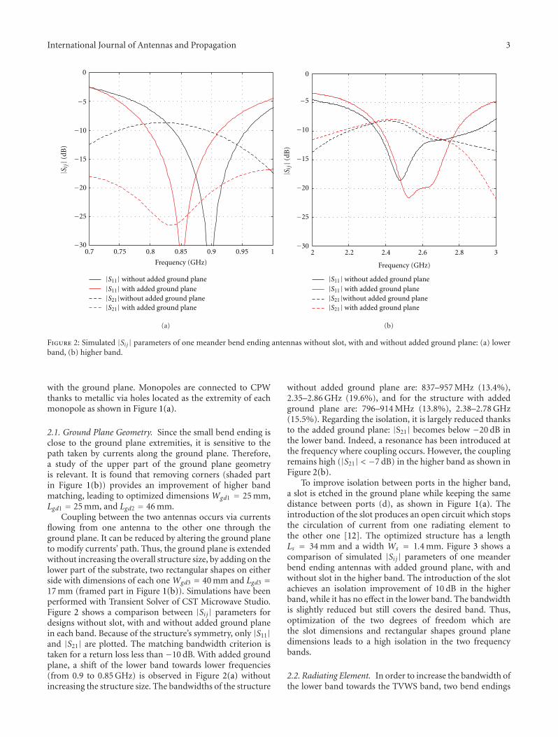
Figure 9 compares the simulated and measured copolarand cross-polar radiation patterns in the E plane (YZ plane)and H plane (XZ plane), respectively. Because both portsare symmetrical, we only represent radiation patterns forport number 1 while port 2 is loaded by 50 ohms. For bothplanes and both bands, it is found that the simulated and themeasured co-polar radiation patterns are in good agreement.The maximum simulated realized gain is 2.5 dB at 778 MHzand 5 dB at 2.6 GHz. The measured cross-polar level is about10 dB lower than the copolar level in the lower band but inthe higher one, the polarization purity is deteriorated. It isprobably due to the proximity of the meander bend endingsto the small one.
To further investigate the diversity, the simulated radia-tion patterns of each radiating element in the XY plane forthe two bands are plotted in Figure 10 (one port is excitedwhile the other one is loaded by 50 ohms). Thanks to agood agreement observed in Figure 9 between simulationsand measurement, only simulations results are presented.As it can be observed for the lower band, the directions

International Journal of Antennas and Propagation 5
Ls
WsS
45◦XY
Z
1 2
Figure 5: A photograph of the prototype with the three meander bend endings antennas.
|S11| simulation
|S21| simulation
|S11|measurement
|S21|measurement
1 1.5 2 2.5−25
−20
−15
−10
−5
0
Frequency (GHz)
|S ij|
(dB
)
Figure 6: Simulated and measured |Si j| parameters of the opti-mized three bend endings antennas with added ground plane andslot.
of the pattern maxima are close to orthogonal, leading togood pattern diversity. Each antenna presents monopole-like radiation patterns. Indeed surface currents are weakon the bend endings. For the higher band, even if patternsare not orthogonal, one monopole presents minimum gaindirections where the other one has a maximum gain, exceptfor the directions θ = ±45◦. This is well-suited to providehigh diversity capabilities.
0.7 0.75 0.8 0.8550
60
70
80
90
100
Frequency (GHz)
Figure 7: Simulated total efficiency in the lower band for theoptimized three bend endings antennas with added ground planeand slot.
4. Evaluation of the Diversity Performance
The diversity performance of a mobile’s antenna systemcan be affected by the environment in which the deviceis located [13]. Therefore, in this section, we evaluate thediversity performance of the proposed three bend endingsantennas with added ground plane and slot, by calculatingthe envelope correlation coefficient (ρe) and the meaneffective gain (MEG) taking into account the propagationenvironment.

6 International Journal of Antennas and Propagation
2.5 2.55 2.6 2.65 2.7
Frequency (GHz)
50
60
70
80
90
100
Figure 8: Simulated total efficiency in the higher band for the optimized three bend endings antennas with added ground plane, and slot.
The envelope correlation ρe quantifies the similaritybetween the radiation patterns of the two monopoles. Thelower the correlation, the better the diversity performance.
Vaughan and Andersen show in [13] that the coefficient canbe expressed by
ρe =∣∣∣
∫
Ω
(
XPDE1θE∗2θ pθ + E1ϕE
∗2ϕpϕ
)
dΩ∣∣∣
2
∫
Ω
(
XPDE1θE∗1θ pθ + E1ϕE
∗1ϕpϕ
)
dΩ∫
Ω
(
XPDE2θE∗2θ pθ + E2ϕE
∗2ϕpϕ
)
dΩ. (1)
E1θ(Ω), E1ϕ(Ω), E2θ(Ω), E2θ(Ω) are simulated complexelectric fields along θ and ϕ radiated by the antenna fed bytwo different ports. The solid angle Ω is defined by θ[0 : π]in elevation and ϕ[0 : 2π] in azimuth. pθ(Ω) and pϕ(Ω) arethe Angle-of-Arrival (AoA) distributions of incoming waves.The parameter XPD is the cross-polarization discriminationof the incident field and is defined as XPD = Sθ/Sϕ (whereSθ and Sϕ represent the average power along the sphericalcoordinates θ and ϕ).
The environment depends strongly on the angles ofarrival distribution and on XPD. The most common dis-tributions proven by measurements are Gaussian (G) andLaplacian (L) distributions [14]. Thus, we consider differentdistributions in elevation, while in azimuth plane (XYplane) the distribution is uniform, as demonstrated by twomeasurement campaigns in the literature [14, 15].
To obtain more realistic results, different environmentsare considered. Each environment is characterized by typicalvalues of XPD, mean angle of incident wave distribution (θi),and standard deviation of wave distribution (σ) [16]. Thesevalues were deduced from several measurements [14–16] fordifferent environments: isotropic, indoor, and outdoor. Theisotropic environment is defined by XPD = 0 dB, pθ(Ω) =pϕ(Ω) = 1, the indoor (In) environment by XPD = 1 dB,θi = 20◦, σ = 30◦, and the outdoor (Out) environment byXPD = 5 dB, θi = 10◦, σ = 15◦.
As antennas will be implemented on a mobile terminal,a study of the effect of the antennas orientation on the
correlation has been done. Three configurations of rotationshave been studied: rotation of antenna around axis A, andaround axis B for two initial positions: horizontal andvertical, as shown in Figure 11.
For each configuration, the envelope correlation coef-ficient for the three meander bend endings antennas withadded ground plane and slot has been calculated fromsimulated radiation patterns. Minimum and maximumvalues at center frequencies of the two bands 777 MHz and2.6 GHz are reported in Table 1.
For isotropic environment, a very low correlation isobserved, in the two bands as a result of good matching(|S11| < −10 dB), a high isolation level (|S21| < −10 dB),and orthogonality between radiation patterns especiallyin the lower band. In addition, polarization diversity isnaturally achieved because of the orthogonal positions ofboth antennas.
For the other cases, maximum values of the correlationenvelope coefficient ρe are close to 0.5 for outdoor environ-ment, whatever the distribution. Indeed, the incoming wavesare mainly along Eθ which implies less diversity in someantenna’s position.
When XPD gets close to 0 dB (indoor environment:XPD = 1 dB), Eθ and Eϕ values are almost the same. Becausethese two components are uncorrelated by definition andbecause each antenna receives preferentially one of eachcomponent, the correlation is getting low.
International Journal of Antennas and Propagation 7
05
15
30
45
60
7590105120
135
150
165
180
−165
−150
−135
−120
−105 −75
−60
−90
−45
−30
−15
−15−10−50
◦◦
◦
◦
◦◦
◦
◦
◦
◦
◦
◦
◦
◦◦ ◦ ◦
◦
◦
◦
◦
◦
◦
◦
±
φ = 90◦
(a)
0
15
30
45
60
7590105120
135
150
165
180
−165
−150
−135
−120
−105 −75
−60
−90
−45
−30
−15
−15−10−50
◦◦
◦
◦
◦◦
◦
◦
◦
◦
◦
◦
◦
◦◦ ◦ ◦
◦
◦
◦
◦
◦
◦
◦
±
φ = 0◦
5
(b)
0
15
30
45
60
7590105120
135
150
165
180
−165
−150
−135
−120
−105 −75
−60
−90
−45
−30
−15
−15−10−50
◦ ◦◦
◦
◦◦
◦
◦
◦
◦
◦
◦
◦
◦◦ ◦ ◦
◦
◦
◦
◦
◦
◦
◦
±5
φ = 90◦
(c)
0
15
30
45
60
7590105120
135
150
165
180
−165
−150
−135
−120
−105 −75
−60
−90
−45
−30
−15
−15−10−50
◦◦
◦
◦
◦◦
◦
◦
◦
◦
◦
◦
◦
◦◦ ◦ ◦
◦
◦
◦
◦
◦
◦
◦
±
φ = 0◦
5
Copolar simulationCopolar measurementCross-polar simulationCross-polar measurement
(d)
Figure 9: Simulated and measured radiation patterns for port 1 (dB): (a) in the E plane (YZ plane) at 778 MHz, (b) in the H plane (XZplane) at the 778 MHz, (c) in the E plane (YZ plane) at 2.6 GHz, and (d) in the H plane (XZ plane) at 2.6 GHz.
For rotation around axis A, minimum values of ρe areobtained for position at which one antenna receives only Eθcomponent of the incoming waves while the other one onlyEϕ component.
For rotation around axis B, for both configurations(b and c), minimum values are obtained when the tworadiating elements are positioned on AB plane. Indeed, at
these positions, the radiation diversity is exploited as shownin Figure 10, and thus a low correlation is obtained.
Finally, for most configurations, envelope correlationcoefficient is less than 0.5 which provides high diversitycapabilities [13]. This result has been achieved thanksto the two orthogonal and identical antennas which arespatially separated. It can provide for either or both spatial

8 International Journal of Antennas and Propagation
0
5
15
30
45
60
7590105120
135
150
165
180
−165
−150
−135
−120
−105 −75
−60
−90
−45
−30
−15
−15−10−50
◦◦
◦
◦
◦◦
◦
◦
◦
◦
◦
◦
◦
◦◦ ◦ ◦
◦
◦
◦
◦
◦
◦
◦
±
φ = 90◦
(a)
05
15
30
45
60
7590105120
135
150
165
180
−165
−150
−135
−120
−105 −75
−60
−90
−45
−30
−15
−15−10−50
◦◦
◦
◦
◦◦
◦
◦
◦
◦
◦
◦
◦
◦◦ ◦ ◦
◦
◦
◦
◦
◦
◦
◦
±
φ = 90◦
Port 1Port 2
(b)
Figure 10: Simulated realized gain (dB) on the XY plane for the twobands: (a) at 778 MHz (b) at 2.6 GHz.
and pattern diversity. In addition, polarization diversity isavailable in the Z-direction.
In the following part, we evaluate the MEG which wasintroduced by Taga [17]. It is defined as the ratio between themean received power of antennas over the random route andthe total mean incident power. When each monopole receivesthe same quantity of power, the MEG ratio (R) of the twoantennas is equal to one, which means that no performancedeterioration is expected due to some power imbalance [18].
A
B
C
(a)
A
B
C
(b)
A
B
C
(c)
Figure 11: Rotation of antenna: (a) around axis A, (b) around axisB (horizontal antenna position), and (c) around axis B (verticalantenna position).
The mathematical expression is given by the followingequation:
MEG =∫
Ω
(XPD
XPD + 1GθPθ +
1XPD + 1
GϕPϕ
)
dΩ, (2)
where Gθ and Gϕ are the θ and ϕ components of theantenna power gain pattern, respectively. The calculatedmean effective gains of the monopoles from simulatedradiation patterns at 777 MHz and 2.6 GHz are presented inTable 2.
The Maximum values of the ratio (R) of MEG1, deter-mined at port 1, over MEG2, determined at port 2, areequal to 1, which satisfy an equal contribution of thetwo monopoles to receive the same quantity of power.The proposed structure is completely symmetric, and theGaussian and Laplacian angular distributions are taken onlyalong the elevation as presented in [15]. In addition, theincident power in the outdoor environment (or indoor) isconcentrated around 10◦ (or 20◦) above the horizon withan aperture of 30◦ (or 60◦), and for these directions bothantennas receive an equal amount of power.
Minimum values of ratio (R) are obtained for positionsat which the Eθ (or Eϕ) components of the two antennashave different levels in the directions of incident power.

International Journal of Antennas and Propagation 9
Table 1: Coefficients of correlation for the two bands for all environments of the proposed structure.
Rotation Distribution777 MHz 2.6 GHz
ρemin ρemax ρemin ρemax
Whatever Isotropic 7.10−5 4.10−3
around A
G-In 0.02 0.10 10−3 0.08
G-Out 0.20 0.42 7.10−4 0.39
L-In 0.07 0.16 10−5 0.22
L-Out 0.26 0.49 3.10−4 0.51
around B (horizontal position)
G-In 7.10−4 0.10 5.10−4 8.10−3
G-Out 10−3 0.42 4.10−5 1.10−2
L-In 2.10−3 0.16 10−5 3.10−3
L-Out 3.10−3 0.46 10−4 5.10−3
around B (vertical position)
G-In 5.10−5 0.05 2.10−4 0.07
G-Out 10−4 0.40 4.10−3 0.39
L-In 2.10−4 0.10 8.10−5 0.22
L-Out 6.10−4 0.49 7.10−4 0.54
Table 2: MEG ratio (R) for the two bands for all environments ofthe proposed structure.
Rotation Distribution777 MHz 2.6 GHz
Rmin Rmax Rmin Rmax
Whatever Isotropic 1 1
around A
G-In 0.70 1 0.78 1
G-Out 0.35 1 0.71 1
L-In 0.63 1 0.46 1
L-Out 0.30 1 0.58 1
G-In 0.99 1 0.99 1
around B G-Out 0.97 1 0.98 1
(horizontal position) L-In 0.99 1 0.99 1
L-Out 0.96 1 0.98 1
G-In 0.94 1 0.80 1
around B G-Out 0.84 1 0.63 1
(vertical position) L-In 0.85 1 0.33 1
L-Out 0.70 1 0.48 1
For example, if antenna 1 presents a low Eθ component whereantenna 2 a high one, an unbalanced power is obtained.
For most configurations, ratio (R) is greater than 0.5which is acceptable to provide high diversity capabilities [18].
5. Conclusion
In this paper, a compact dual-band, dual-polarized antennafor LTE applications is proposed, with an extension of thelower band towards TV White Space band, to provide radio-cognitive capabilities to the terminal. A design provides dualpolarizations in both of the bands: 700–862 MHz and 2.5–2.69 GHz with good impedance matching (|S11| < −10 dB).
Measurement results are in good agreement with sim-ulated ones. In addition, good performances are obtainedby calculating the envelope correlation coefficient and theMEG ratio for several antennas’ positions in different
environments: isotropic, indoor, and outdoor. For mostconfigurations, it is found that the system satisfies thecondition ρe < 0.5 and MEG1/MEG2 > 0.5. Thus, thepresented design is suitable for MIMO communicationapplications, and thus enables the SNR value at the terminalside to be maximized.
Acknowledgment
The research leading to these results has received fundingfrom the European Community’s Seventh Framework Pro-gram (FP7/2007–2013) under Grant agreement SACRA no.249060.
References
[1] 3rd Generation Partnership Project, Technical SpecificationGroup Radio Access Network, Evolved Universal TerrestrialRadio Access (E-UTRA) Radio Resource Control (RRC),Protocol Specification, 3GPP TS 36. 331.
[2] R. G. Vaughan, “Polarization diversity in mobile communica-tions,” IEEE Transactions on Vehicular Technology, vol. 39, no.3, pp. 177–186, 1990.
[3] K. Ogawa and T. Uwano, “Diversity antenna for very small800-MHz band portable telephones,” IEEE Transactions onAntennas and Propagation, vol. 42, no. 9, pp. 1342–1345, 1994.
[4] J. W. Wallace, M. A. Jensen, A. L. Swindlehurst, and B. D.Jeffs, “Experimental characterization of the MIMO wirelesschannel: data acquisition and analysis,” IEEE Transactions onWireless Communications, vol. 2, no. 2, pp. 335–343, 2003.
[5] S. Hienonen, A. Lehto, and A. V. Raisanen, “Simple broad-band dual-polarized aperture-coupled microstrip antenna,”in Proceedings of the IEEE Antennas and Propagation SocietyInternational Symposium, vol. 2, pp. 1228–1231, Orlando, Fla,USA, August 1999.
[6] P. Brachat and J. M. Baracco, “Printed radiating element withtwo highly decoupled input ports,” Electronics Letters, vol. 31,no. 4, pp. 245–246, 1995.
[7] Y. L. Kuo and K. L. Wong, “Dual-polarized monopole antennafor WLAN application,” in Proceedings of the IEEE Antennas

10 International Journal of Antennas and Propagation
and Propagation Society International Symposium, vol. 4, pp.80–83, June 2002.
[8] C. Yang, Y. Yao, J. Yu, and X. Chen, “Novel compact multibandMIMO antenna for mobile terminal,” International Journalof Antennas and Propagation, vol. 2012, Article ID 691681, 9pages, 2012.
[9] T. W. Chiou and K. L. Wong, “A compact dual-band dual-polarized patch antenna for 900/1800-MHz cellular systems,”IEEE Transactions on Antennas and Propagation, vol. 51, no. 8,pp. 1936–1940, 2003.
[10] K. S. Kim, T. Kim, and J. Choi, “Dual-frequency aperture-coupled square patch antenna with double notches,”Microwave and Optical Technology Letters, vol. 24, no. 6, pp.370–374, 2000.
[11] SACRA European Project, (FP7/ 2007–2013), http://www.ict-sacra.eu/.
[12] K. J. Kim, W. G. Lim, and J. W. Yu, “High isolation internaldual-band planar inverted-F antenna diversity system withband-notched slots for MIMO terminals,” in Proceedings of the36th European Microwave Conference (EuMC’06), pp. 1414–1417, Manchester, UK, September 2006.
[13] R. G. Vaughan and J. B. Andersen, “Antenna diversityin mobile communication,” IEEE Transactions on VehicularTechnology, vol. 36, no. 4, pp. 149–172, 1987.
[14] K. Kalliola, K. Sulonen, H. Laitinen, O. Kivekas, J. Krogerus,and P. Vainikainen, “Angular power distribution and meaneffective gain of mobile antenna in different propagationenvironments,” IEEE Transactions on Vehicular Technology, vol.51, no. 5, pp. 823–838, 2002.
[15] F. Adachi, M. T. Feeney, A. G. Williamson, and J. D. Parsons,“Crosscorrelation between the envelopes of 900 MHz signalsreceived at a mobile radio base station site,” Proceedings of IEEon Communications, Radar and Signal Processing Part F, vol.133, no. 6, pp. 506–512, 1986.
[16] Z. Ying, T. Bolin, V. Plicanic, A. Derneryd, and G. Kristensson,“Diversity antenna terminal evaluation,” in Proceedings ofthe IEEE Antennas and Propagation Society InternationalSymposium and USNC/URSI Meeting, pp. 375–378, July 2005.
[17] T. Taga, “Analysis for mean effective gain of mobile antennasin land mobile radio environments,” IEEE Transactions onVehicular Technology, vol. 39, no. 2, pp. 117–131, 1990.
[18] W. C. T. Brown, Antenna diversity for mobile terminal[Ph.D. thesis], University of Surrey, 2002, http://epubs.surrey.ac.uk/2125/.