compact disc terminology - jmargolin.com technology and standards of compact discs are growing and...
TRANSCRIPT

Disc Manufacturing, Inc.A QUIXOTE COMPANY
Compact DiscTerminology
Second Edition
Disc Manufacturing, Inc.1409 Foulk Road , Su i te 102
W i l m i n g t o n , D E 1 9 8 0 31 - 8 0 0 - 4 3 3 - D I S C • ( 3 0 2 ) 4 7 9 - 2 5 0 0
Copyright 1993 By Disc Manufacturing , Inc . Al l r ights reserved.

WHO IS DMI?
Disc Manufacturing, Inc. (DMI) manufactures all compact disc formats (i.e., CD-Audio,CD-ROM, CD-ROM XA, CDI, PHOTO CD, 3DO, KARAOKE, etc.) at two plant sites inthe U.S.; Huntsville, AL, and Anaheim, CA. To help you, DMI has one of the largestProduct Engineering/Technical Support staff and sales force dedicated solely toCD-ROM in the industry.
The company has had a long term commitment to optical disc technology and hasperformed developmental work and manufactured (laser) optical discs of various typessince 1981. In 1983, DMI manufactured the first compact disc in the United States. DMIhas developed extensive mastering expertise during this time and is frequently calledupon by other companies to provide special mastering services for products indevelopment.
In August 1991, DMI purchased the U.S. CD-ROM business from the Philips andDu Pont Optical Company (PDO). PDO employees in sales, marketing and technicalservices were retained.
DMI is a wholly-owned subsidiary of Quixote Corporation, a publicly owned corporationwhose stock is traded on the NASDAQ exchange as QUIX. Quixote is a diversifiedtechnology company composed of Energy Absorption Systems, Inc. (manufactureshighway crash cushions), Stenograph Corporation (manufactures shorthand machines andcomputer systems for court reporting) and Disc Manufacturing, Inc.
We would be pleased to help you with your CD project or answer any questions you mayhave. Please give us a call at 1-800-433-DISC for pricing or further information.
We have four additional technical papers available entitled
Integrating Mixed-Mode CD-ROM
An Overview to MultiMedia CD-ROM Production
Introduction to ISO 9660
A Glossary of CD and CD-ROM Terms
These are available upon request800-433-DISC302-479-2500
Fax: 302-479-2527

We wish to thank the following organizations for helping to make this paper complete andaccurate:
Eastman Kodak Company
Philips International Media of America
We would also like to thank Pamela A. Sansbury and Nancy A. Klocko for theirinvolvement in the editing process.
For additional copies of this paper or reprinting privileges, please write to:
Nancy KlockoDisc Manufacturing, Inc.
1409 Foulk Road, Suite 102Wilmington, DE 19803
Phone: 1-800-433-DISC or 1-302-479-2500FAX: 1-302-479-2527
Applelink: DMI.CD
Authors:
J. Philip BuskClayton SummersC. Steven LangerJames R. Fricks
Page - 2

IndexOverview.... . . . . . . . . . . . . . . . . . . . . . . . . . . . . . . . . . . . . . . . . . . . . . . . . . . . . . . . . . . . . . . . . . . . . . . . . . . . . . . . . . . . . . . .4Red Book - CD Audio Standard.................................................................7Yellow Book - CD-ROM Standard..............................................................8
Yellow Book - CD-ROM Mode 1......................................................8Yellow Book - CD-ROM Mode 2......................................................8
Mixed Mode Disc..................................................................................10CD-ROM/XA (Extension to CD-ROM Standard)............................................12Green Book (CD-I Standard)...................................................................16CD-I Ready Format...............................................................................18CD-Bridge Disc....................................................................................19
Photo CD..... . . . . . . . . . . . . . . . . . . . . . . . . . . . . . . . . . . . . . . . . . . . . . . . . . . . . . . . . . . . . . . . . . . . . . . . . . . . . .21KARAOKE CD...........................................................................23
Orange Book (Recordable Compact Disc Standard)..........................................24Orange Book Part I - CD-MO...........................................................24Orange Book Part II - CD-WO ... . . . . . . . . . . . . . . . . . . . . . . . . . . . . . . . . . . . . . . . . . . . . . . . . . . . . . .24
ISO 9660.... . . . . . . . . . . . . . . . . . . . . . . . . . . . . . . . . . . . . . . . . . . . . . . . . . . . . . . . . . . . . . . . . . . . . . . . . . . . . . . . . . . . . . . .28Non ISO 9660...... . . . . . . . . . . . . . . . . . . . . . . . . . . . . . . . . . . . . . . . . . . . . . . . . . . . . . . . . . . . . . . . . . . . . . . . . . . . . . . .32Additional Technologies..........................................................................33
3DO.... . . . . . . . . . . . . . . . . . . . . . . . . . . . . . . . . . . . . . . . . . . . . . . . . . . . . . . . . . . . . . . . . . . . . . . . . . . . . . . . . . . . .33DVI... . . . . . . . . . . . . . . . . . . . . . . . . . . . . . . . . . . . . . . . . . . . . . . . . . . . . . . . . . . . . . . . . . . . . . . . . . . . . . . . . . . . . . .33CDTV.... . . . . . . . . . . . . . . . . . . . . . . . . . . . . . . . . . . . . . . . . . . . . . . . . . . . . . . . . . . . . . . . . . . . . . . . . . . . . . . . . . .33
Where To Get Additional Information..........................................................34Appendix A
Control Bytes (Subcode Channels P through W) .. . . . . . . . . . . . . . . . . . . . . . . . . . . . . . . . . . .35Subcode Channel P .. . . . . . . . . . . . . . . . . . . . . . . . . . . . . . . . . . . . . . . . . . . . . . . . . . . . . . . . . . . . . . . . . . . . .35Subcode Channel Q......................................................................35Subcode Channels R Through W, (CD + Graphics).................................36
Appendix BCD-Encoding Overhead .. . . . . . . . . . . . . . . . . . . . . . . . . . . . . . . . . . . . . . . . . . . . . . . . . . . . . . . . . . . . . . . .38
Appendix CCD-I Ready Disc Layout .. . . . . . . . . . . . . . . . . . . . . . . . . . . . . . . . . . . . . . . . . . . . . . . . . . . . . . . . . . . . . . .40
Appendix DCompact Disc Layout....................................................................41
Appendix EPlayability Matrix.........................................................................42
Appendix FTransition Between Tracks (Pre-gap, Post-gap, and Pause)........................43
Appendix GCalculating Available User's Data......................................................44
Appendix HFull-Motion Video........................................................................45
Appendix ITechnical Breakdown of how sectors are put on a CD. .. . . . . . . . . . . . . . . . . . . . . . . . . . . .46
Diagrams:
Diagram of Standards .............................................................. 5Diagram of Sectors.................................................................. 6Diagram of Orange Book .......................................................... 27Appendix C: Layout of CD-I Ready Disc Image .............................. 40Appendix D: Compact Disc Layout.............................................. 41Appendix F: Transition Between Tracks (Pre-gap, Post-gap, and Pause).. 43Appendix I: Technical Breakdown of how sectors are put on a CD ....... 46
Page - 3

COMPACT DISC T E R M I N O L O G Y
OVERVIEW
The compact disc industry has been rapidly growing since its inception back in 1980. One of themajor reasons for this phenomenal growth is the standards and formats on which the compactdisc industry is based. These standards and format have paved the way for CD's to become alow cost and reliable vehicle for information exchange.
The technology and standards of compact discs are growing and changing extremely fast. Theopportunities and potential for information delivery are limitless. As more people andorganizations consider CD technology, adherence and knowledge of the CD standards andformats will become even more important and necessary.
The following paper revises and updates Disc Manufacturing, Inc.'s 1992 Compact DiscTerminology publication which discussed compact disc standards, formats, and technology.This paper is intended to be for the readers information only. Please consult the appropriatetechnical information that is available from the companies listed on Page 36 before beginning anyCD development project.
The four major standards and their application areas which govern almost all types of compactdisc technology are as follows:
Standard: Application:
Red Book AudioYellow Book CD-ROMGreen Book CD-IOrange Book Recordable CD's
The above standards lay the foundation from which all other standards and technologies arederived. Some of the other standards and technologies discussed in this paper are as follows:
Mixed Mode Disc KARAOKE CDCD-ROM/XA DVICD-I Ready Disc CDTVCD-Bridge Disc Photo CDCD+G Video CD (Full-Motion Video/White Book)
A diagram of CD standards and formats can be found in Figure 1.0 on Page 7 . A diagram ofCD sector layouts can be found of Page 8.
The ISO 9660 logical file format has gained acceptance as the standard file format of CD-ROMdevelopment and delivery. A general overview of this format (including extensions) is discussedon Page 30.
We hope that the reader finds the information in this paper to be beneficial. If we can provideyou with any additional information, please let us know.
Disc Manufacturing, Inc. hopes to have the opportunity to work with you on your CD projects.
Please feel free to contact us at 1-800-433-DISC or 1-302-479-2500.
Page - 4

Each track on a compact disc can be one and only one of the following: CD-Audio, CD-ROM Mode 1,CD-ROM Mode 2, CD-ROM/XA, or CD-I. The whole track must be the same type. When you combinedifferent types of tracks on the same disc, the disc is called mixed mode disc. For example: Track 1could be CD-ROM Mode 1 data and tracks 2 and up could be audio data. This is the most commontype of Mixed Mode Disc.
Diagram of CD Standards and Formats
CD-ROM (Yellow Book)Defines Computer Data Format
CD-DA (Red Book)Defines Digital Audio Format
M o d e 1 ( 2 0 4 8 B y t e s )Additional EDC/ECC
M o d e 2 ( 2 3 3 6 B y t e s ) *No Additional EDC/ECC
I S O 9 6 6 0o r
High SierraStandards
Non ISO9 6 6 0
or NonHigh SierraProprietary
HybridD i s c
L e v e l1
Inter-c h a n g e
L e v e l2
Inter-c h a n g e
Form 12 0 4 8B y t e s
Form 22 3 2 4B y t e s
Form 12 0 4 8B y t e s
Form 22 3 2 4B y t e s
Orange BookDefines CD-MO & CD-WO
CD-ROM/XA
CD-I(Green Book)
BridgeDisc
M i x e dModeD i s c
CD-IReadyD i s c
Examples:Photo CD
KARAOKE CD/Video CD
"White Book"
Example:Audio &
Data Tracks on
Same Disc
Examples:DOSUNIXDVI
Examples:CDTVAppleUNIX
Example:ISO 9660 DOS& HFS ImagesOn Same Disc
Example:Apple HFS
AdditionalEDC/ECC
No AdditionalEDC/ECC
No AdditionalEDC/ECC
AdditionalEDC/ECC
The Orange Book is a standard that governs thecreation of Compact Disc-Magneto Optical (CD-MO) and Compact Disc-Write Once (CD-WO) discs. Audio and/or data in anyof the above formats can be recorded toa disc. Please see page 29, Figure 3.0, fora diagram of the Orange Book standard.
Figure 1.0
+
Red BookIncludes
CD+G
* Please note that the information located below the Mode 1 block (ISO 9660 & Non ISO 9660) can also apply to a Mode 2 disc.
Page - 5

.
Sync12
Header4
User Data2336
2352 Byte Layout for CD-ROM Mode 2
Sync12
Header4
Sub-Header8
User Data2048
EDC4
ECC276
Sync12
Header4
Sub-Header8
User Data2324
EDC4
2352 Byte Layout for CD-ROM Mode 2 / XA Form 1
2352 Byte Layout for CD-ROM Mode 2 / XA Form 2
Sync12
Header4
User Data2048
EDC4
ECC276
2352 Byte Layout for CD-ROM Mode 1
blanks8
User Data2352
Data Layout in a CD-Audio Sector (1/75 second)
Diagram of Sector Layouts
Red Book:
Yellow Book:
CD-ROM / XA and Green Book:
2352 bytes
2352 bytes
2352 bytes
2352 bytes
2352 bytes
Figure 2.0
Page - 6

Red Book - CD Audio Standard
The compact disc industry started in 1980 when Philips and Sony introduced the Compact DiscDigital Audio Standard. This is commonly called the Red Book. The Red Book describes theAudio Compact Disc (CD) that you find in music stores today. It is the foundation on which allother CD standards are built. Because audio discs are manufactured per the Red Book Standard,all audio compact discs will play in any audio compact disc player. This interchangeability hasbeen a major factor in the growth of the CD music industry.
The track type defined in the Red Book is: CD-Digital-Audio (CD-DA), for audio music. TheRed Book specifies that the audio data is on the CD in one or more tracks. Each track isnormally one song. These tracks are further subdivided into sectors that are 1/75th of a secondin length and contain 2352 bytes of audio data in digital form. A maximum of 99 audio tracksmay be placed on a standard Red Book disc.
In addition to the 2352 bytes of audio data, the Red Book specifies the addition of 2 layers oferror detection and error correction code (EDC/ECC). The compact disc utilizes the CrossInterleave Reed-Solomon Code (CIRC) in its first two layers of error protection. If a disc getsscratched or dirty and a laser can not read the data, the CD player uses the CIRC to recreate themusic.
The Red Book not only defines how to put audio on a CD, it also defines a way to add graphicsinformation to the CD. This type of disc is commonly referred to as a CD+G disc, or "CD plusgraphics" disc. Approximately 16MB worth of graphics (user data) can be stored in the subcode(channels R through W) of a 74 minute Red Book disc. More information on a CD+G disc canbe found in Appendix A on Page 37.
User Data
Data Layout in a CD-Audio Sector (1/75 second)
2352 bytes
2352
Page - 7

Yellow Book - CD-ROM Standard
In 1984 Philips and Sony introduced the CD-ROM (Compact Disc Read Only Memory)Standard. This standard is commonly known as the Yellow Book (Refer to Diagram ofStandards, Figure 1.0, Page 7). The Yellow Book further defines the Red Book by adding twonew types of tracks.
The track type defined in the Red Book is:
* CD-Audio, for audio music.
The two new track types defined in the Yellow Book are:
* CD-ROM Mode 1, usually used for computer data. * CD-ROM Mode 2, usually used for compressed audio data, and video/picture
data. Also, usually further defined as XA.
The CD-ROM Mode 1 and Mode 2 tracks use the Red Book specifications as a foundation. Thisincludes the Red Book 1st and 2nd layer CIRC error correction and control bytes (see AppendixA). The difference between the Red Book and the Yellow Book is a redefinition of the 2352 byteRed Book data area.
Yellow Book - CD-ROM Mode 1
CD-ROM Mode 1 redefines the Red Book 2352 byte data area as:
12 bytes of synchronization4 bytes of header information2048 bytes of user data288 bytes of error correction and detection codes
Sync12
Header4
User Data2048
EDC4
ECC276
2352 Byte Layout for CD-ROM Mode 1
blanks8
2352 bytes
The first 16 bytes contain the Synchronization and Header Information. The computer uses thisinformation to identify which sector it is reading.
The next 2048 bytes contain the Users Data.
The last 288 bytes contain an additional layer (3rd layer) of error detection and error correctioncode, that is included in a Mode 1 sector to provide the increased reliability needed for computerdata.
Yellow Book - CD-ROM Mode 2
CD-ROM Mode 2 redefines the 2352 byte area as:
12 bytes of synchronization
Page - 8

4 bytes of header information2336 bytes of user data
Sync12
Header4
User Data2336
2352 Byte Layout for CD-ROM Mode 2
2352 bytes
The first 16 bytes contain the Synchronization and Header Information. The computer uses thisinformation to determine which sector it is reading.
The next 2336 bytes contain the Users Data. Mode 2 does not have the additional EDC/ECCthat Mode 1 has. Mode 2 allows the user to have 14% more data than Mode 1, but with lesserror correction capability.
CD-ROM Mode 2 as shown, which is not in XA format, is an extremely rare form. Normally,Mode 2 discs are always in the XA format. (See section on XA, Page 14.) Although Mode 2non XA discs can be read by a normal CD-ROM drive, they require special custom software todecode and interface.
Even though CD-ROM Mode 2 does not have the additional layer (3rd layer) of error detectionand correction like Mode 1, it does have the 2 layers (CIRC) of error detection and correctiondefined in the Red Book.
Page - 9
Mixed Mode Disc
When a CD has data (CD-ROM) and audio (CD-DA) tracks, it is referred to as a Mixed Modedisc.
The most common type of Mixed Mode disc is one where the 1st track on the disc is Mode 1data, and the remaining tracks on the disc are audio tracks. Refer to Diagram of Standards,Figure 1.0, Page 7. The maximum number of tracks (data and audio) on a mixed mode disc is99.
CAUTION: The above type of Mixed Mode disc can be played in a audio CD player. If youplay the CD-ROM track (or track 1), it will sound like FULL VOLUME STATIC on someCD players and may damage your speakers as well as your ear drums. (Most newer audioplayers will mute the CD-ROM track.)
When planning to make a Mixed Mode Disc, remember the CD-ROM Player can only read onetrack at a time.
The two most common methods used in playing Mixed Mode applications are:
a) To copy the program and data onto the computer and run the program from the computermemory while playing audio tracks on the CD-ROM drive. This allows the program tohave continuous access to the audio. The limitation is that you must have enough memoryin the computer to load the program and data before starting the application.
b) To alternately read in a portion of the program and data. While running the portion of theprogram that was read in, the CD-ROM drive can play audio as needed. The limitationoccurs when you need to read the next program segment. At this time, the audio must bestopped, in order to enable the CD-ROM drive to read the next portion of data.
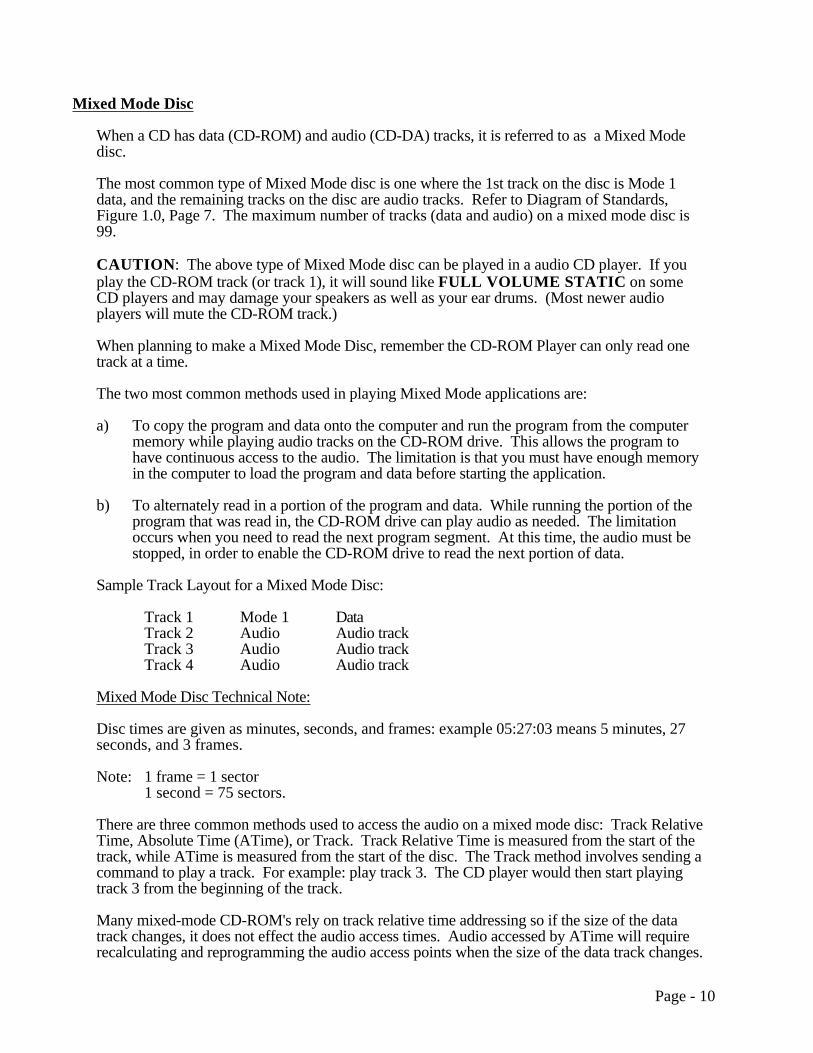
Sample Track Layout for a Mixed Mode Disc:
Track 1 Mode 1 DataTrack 2 Audio Audio trackTrack 3 Audio Audio trackTrack 4 Audio Audio track
Mixed Mode Disc Technical Note:
Disc times are given as minutes, seconds, and frames: example 05:27:03 means 5 minutes, 27seconds, and 3 frames.
Note: 1 frame = 1 sector1 second = 75 sectors.
There are three common methods used to access the audio on a mixed mode disc: Track RelativeTime, Absolute Time (ATime), or Track. Track Relative Time is measured from the start of thetrack, while ATime is measured from the start of the disc. The Track method involves sending acommand to play a track. For example: play track 3. The CD player would then start playingtrack 3 from the beginning of the track.
Many mixed-mode CD-ROM's rely on track relative time addressing so if the size of the datatrack changes, it does not effect the audio access times. Audio accessed by ATime will requirerecalculating and reprogramming the audio access points when the size of the data track changes.
Page - 10

For example, if a program wants to play the audio section shown in Part A of the diagram below,it would play the following times:
using Track Relative Times: Start at 05:27:00 and End at 10:13:07using ATimes: Start at 19:27:05 and End at 24:13:12
If the size of the data track increases by 4 minutes as shown in Part B of the diagram below, andthe program wants to play the same audio section in track #3, then it would play the followingtimes:
using Track Relative Times: Start at 05:27:00 and End at 10:13:07using Absolute Times: Start at 23:27:05 and End at 28:13:12
Notice that the program using Track Relative Times for accessing the audio does not have to bechanged when the size of the data track changes. However, a program that uses ATime foraccessing the audio has to be recalculated and reprogrammed when the size of the data trackchanges.
A thorough discussion of Mixed Mode discs can be found in the Disc Manufacturing, Inc. paperIntegrating Mixed-Mode CD-ROM by J. Philip Busk.
00:00:00 00:00:00
ATime Track Relative Time
05:12:15 00:00:00
14:00:05 00:00:00
19:27:05 05:27:00
24:13:12 10:13:07
27:15:15 00:00:00
DataTrack #1
AudioTrack #2
AudioTrack #3
AudioTrack #4
Section oftrack #3 wewant to play.
00:00:00 00:00:00
ATime Track Relative Time
09:12:15 00:00:00
18:00:05 00:00:00
23:27:05 05:27:00
28:13:12 10:13:07
31:15:15 00:00:00
DataTrack #1
AudioTrack #2
AudioTrack #3
AudioTrack #4
Section oftrack #3 wewant to play.
Track Layout for Mixed Mode DiscBefore Data Size Increases:
Track Layout for Mixed Mode DiscAfter Data Size Increases:
Part A Part B
Please note that track pregap, postgap, and pause are not shown in the above diagramto simplify the illustration. Information on track pregap, postgap, and pause can be found in Appendix F on Page 45.
Page - 11
CD-ROM/XA (Extension to CD-ROM Standard)
In 1989, the CD-ROM/XA standard was issued by Philips, Microsoft, and Sony (Refer toDiagram of Standards, Figure 1.0, Page 7). This standard is an extension to the Yellow Bookand defines a new type of track.
XA allows computer data and Adaptive Pulse Code Modulation (ADPCM) audio data to be puton the same track. Computer data can be put on the track as Form 1 and ADPCM audio and/orvideo/picture data can be put on the track as Form 2 data. Because both Form 1 and Form 2 are"CD-ROM Mode 2, XA Format", they can both be on the same track. With the properinterleaving of Form 1 and Form 2, a track can play back audio, video, and computer data atwhat appears to be the same time.
Compare this to the Mixed Mode disc defined on Page 12. A mixed mode disc has computerdata on one track and Red Book audio data on another track. A CD-ROM drive reading a MixedMode disc CAN NOT read computer data while it is playing audio. The XA disc hascompressed ADPCM audio and computer data interleaved on the same track, so it can read thecomputer data and play the ADPCM audio at what appears to be the same time. This is theadvantage of the XA standard.
In CD-ROM/XA Mode 2, Form 2, the audio must be in a compressed format to allow space forthe Sync, Header, and Subheader in the sector and for the interleaved computer data on the track.Adaptive Pulse Code Modulation (ADPCM) is a compression scheme used by the CD-ROM/XA(and CD-I) format. In the simplest terms, the audio file structure is interleaved with the data.This compressed audio is not as high quality as the full stereo quality on a normal audio track asdefined by the Red Book. The Red Book defines 16 bit samples at a 44.1 KHz sampling rate.ADPCM defines several audio compression levels, ranging from a voice quality level C definedas 4 bit samples at a 18.9 KHz sampling rate; up to a music quality level B defined as 4 bitsamples at a 37.8 KHz sampling rate. (See section on Audio Compression Levels for CD-ROM/XA, located on Page 17.)
More information on sampling rates can be found in the Disc Manufacturing, Inc. paperIntegrating Mixed-Mode CD-ROM by J. Philip Busk.
The track type defined in the Red Book is:
* CD-Digital Audio, for audio music. (not compressed)
The track types defined in the Yellow Book are:
* CD-ROM Mode 1, usually used for computer data. * CD-ROM Mode 2, usually used for compressed audio data, and
video/picture data. Also, usually further defined as XA.
The new track type defined by CD-ROM / XA is:
* CD-ROM Mode 2, XA Format, usually used for computer data, compressed audio data, and/or video/picture data.
A CD-ROM / XA track interleaves Mode 2 compressed ADPCM audio and Mode 2 data sectors.Additional hardware is needed to separate these when playing the disc. The hardware isprogrammed to separate the audio from the data (The Coding Information contained in the Sub-Header tells the computer which sectors are audio and which sectors are data.), decompress the
Page - 12

audio and play it out through the audio jacks. At the same time, the hardware passes the data tothe computer. The above two processes appear to be happening simultaneously to the user.
Audio Sector Interleaving:
The table below illustrates the necessary interleaving patterns using B level and C level ADPCMencoding. The ratio of data sectors that may be interleaved between each ADPCM audio sector isalso shown. The interleaved data sectors may contain data, video, or empty sectors.
SectorsLevel 0 1 2 3 4 5 6 7 8 9 10 11 12 13 14 15
B Stereo A d d d A d d d A d d d A d d dRatio1:3
B Mono A d d d d d d d A d d d d d d dRatio1:7
C Stereo A d d d d d d d A d d d d d d dRatio1:7
C Mono A d d d d d d d d d d d d d d dRatio1:15
A= ADPCM audio sectors, tagged with the same File & Channel Number in theSub-header field.
d= Data sectors (data, video, or ADPCM audio with other File Numbers andChannel Numbers assignments).
Notice in the above table that as the quality of the ADPCM audio increases the amount of datainterleaved between decreases.
Current CD-ROM players need additional hardware to play XA discs. Several drivemanufacturers are offering XA interface cards as well as drives that have integrated XA support.The XA interface card plugs into your computer and connects to the CD-ROM drive with a cable.The card decompresses the audio data and outputs it to the speaker system while it passes thecomputer data to the computer for processing.
CD-ROM / XA defines 8 bytes of the 2352 byte area as a "Sub-Header". The Sub-Headercontains the following information:
File Number: The File Number identifies all the sectors that belong to the same file.
Channel Number: The Channel Number helps in the real-time selection of the different pieces of information that need to be chosen from an interleaved file.
Submode: The global attributes of a sector as required for the initial selection and allocation of a sector in the system is definedby the Submode.
Page - 13
Coding Information: The details of the type of data located in the user area of the sector is defined by the Coding Information.
The coding information in the sub-header defines two types of CD-ROM / XA sectors:
* CD-ROM Mode 2, XA Format, Form 1 -- usually used for computer data. * CD-ROM Mode 2, XA Format, Form 2 -- usually used for compressed audio
data and/or video/picture data.
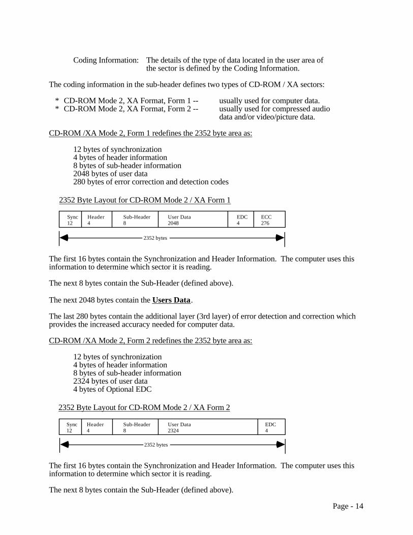
CD-ROM /XA Mode 2, Form 1 redefines the 2352 byte area as:
12 bytes of synchronization4 bytes of header information8 bytes of sub-header information2048 bytes of user data280 bytes of error correction and detection codes
Sync12
Header4
Sub-Header8
User Data2048
EDC4
ECC276
2352 Byte Layout for CD-ROM Mode 2 / XA Form 1
2352 bytes
The first 16 bytes contain the Synchronization and Header Information. The computer uses thisinformation to determine which sector it is reading.
The next 8 bytes contain the Sub-Header (defined above).
The next 2048 bytes contain the Users Data.
The last 280 bytes contain the additional layer (3rd layer) of error detection and correction whichprovides the increased accuracy needed for computer data.
CD-ROM /XA Mode 2, Form 2 redefines the 2352 byte area as:
12 bytes of synchronization4 bytes of header information8 bytes of sub-header information2324 bytes of user data4 bytes of Optional EDC
Sync12
Header4
Sub-Header8
User Data2324
EDC4
2352 Byte Layout for CD-ROM Mode 2 / XA Form 2
2352 bytes
The first 16 bytes contain the Synchronization and Header Information. The computer uses thisinformation to determine which sector it is reading.
The next 8 bytes contain the Sub-Header (defined above).
Page - 14

The next 2324 bytes contain the Users Data. Form 2 does not have the additional EDC/ECCthat Form 1 has. Form 2 allows the user to have 13% more data than Form 1, but with less errorcorrection capability.
Developers need additional software and/or hardware to compress the audio and video data tothis format. They also need pre-mastering software to interleave the files.
As mentioned before unless the CD-ROM drive is a purely XA drive an additional board willneed to be added to play CD-ROM/XA discs. This board facilitates the separation and decodingof ADPCM audio from the data.
Audio Compression Levels for CD-ROM / XA:
(Based on a disc capacity of 75 minutes.)
In the following table, CD-DA is included as a comparison. CD-DA (Red Book Audio) canNOT be put on a CD-ROM / XA track. However, it is possible to put CD-ROM/XA and CD-DAtracks on the same disc. This disc would be a type of "mixed mode" disc. Also note that theCD-I audio level A is not defined in the CD-ROM/XA specification.
Maximum Playing Time Sampling size and rate Bytes Needed to Store1 Minute of StereoAudio (MB)
CD-DA 1.25 hours (stereo) 16 bit samples 44,100 samples per second 10.09Level B 5 hours (stereo)
10 hours (mono)4 bit samples 37,800 samples per second 2.16
Level C 10 hours (stereo)20 hours (mono)
4 bit samples 18,900 samples per second 1.08
The above playing times are "Maximum" playing times which assume you only have thecompressed audio on the disc. If you add any form of data (data and/or video data) the amountof compressed audio must be reduced to make room for this data.
Example: (Based on a disc capacity of 75 minutes)
If you have 10 hours of Level B compressed mono sound on the disc, there will be no room fordata. If you have 5 hours of Level B compressed mono sound on the disc, there will be roomfor 330 MBytes of data in CD-ROM / XA form 1 sector format. The following table providesadditional times and capacities:
Amount of Level B Mono on Disc Amount of room for Form 1 data on Disc
10 hours 0 MBytes7.5 hours 165 MBytes5 hours 330 MBytes
2.5 hours 495 MBytes0 hours 660 MBytes
Page - 15

Green Book (CD-I Standard)
The Compact Disc Interactive (CD-I) Media standard was released in 1987 by Philips. Thisstandard specifies the CD-I disc layout and an operating system called CD-RTOS. Thisspecification is known as the Green Book Standard (Refer to Diagram of Standards, Figure 1.0,Page 7). Like CD-ROM/XA (see Page 14), this standard allows for the interleaving of computerdata and compressed audio on the same track. The CD-I track is not shown in the table ofcontents on the disc. This prevents audio players from playing the CD-I track. A CD-I systemconsists of a stand alone CD-I player connected to a TV set.
The sector layouts for CD-I are identical to CD-ROM / XA. Please refer to the CD-ROM/XAsection (Page 14) for a more detailed discussion of the sector layouts.
Sector Layout for CD-I and CD-ROM / XA:
Sync12
Header4
Sub-Header8
User Data2048
EDC4
ECC276
Sync12
Header4
Sub-Header8
User Data2324
EDC4
2352 Byte Layout for CD-ROM Mode 2 / XA Form 1
2352 Byte Layout for CD-ROM Mode 2 / XA Form 2
2352 bytes
2352 bytes
Audio Compression Levels for CD-I:
(Based on a disc capacity of 75 minutes.)
Adaptive Pulse Code Modulation (ADPCM) is a compression scheme used by the CD-I (and CD-ROM/XA) format. In the simplest terms, the audio file structure is interleaved with the data.This compressed audio is not as high quality as the full stereo quality on a normal audio track asdefined by the Red Book. Levels A, B, and C, ADPCM are defined for CD-I audio.
In the following table, CD-DA is included as a comparison. CD-DA (Red Book Audio) canNOT be put on a CD-I track. However, it is possible to put CD-I and CD-DA tracks on the samedisc. This disc would be a type of "mixed mode" disc. CD-I players are capable of playing CD-DA tracks as well as Photo CD's (See Page 23).
Page - 16

Maximum Playing Time Sampling size and rate Bytes Needed to Store1 Minute of StereoAudio (MB)
CD-DA 1.25 hours (stereo) 16 bit samples 44,100 samples per second 10.09Level A 2.50 hours (stereo)
5 hours (mono)8 bit samples 37,800 samples per second 4.33
Level B 5 hours (stereo)10 hours (mono)
4 bit samples 37,800 samples per second 2.16
Level C 10 hours (stereo)20 hours (mono)
4 bit samples 18,900 samples per second 1.08
The above playing times are "Maximum" playing times which assume you only have thecompressed audio on the disc. If you add any form of data (data and/or video data) the amountof compressed audio must be reduced to make room for this data.
CD-I MPEG 1 Full-Motion Video (FMV)/Video CD:
It is possible to display Full-Motion Video on a television screen using a CD-I player that has anoptional or integrated Full-Motion Video adapter installed. A Full-Motion Video adapter must beinstalled on the CD-I player to decompress MPEG data. Full-Motion Video on a CD is alsoreferred to as Video CD. Full-Motion Video or Video CD is based on the White Book standard.More information on this standard can be found in Appendix H on Page 47.
The CD-I format adopted the MPEG 1 (Moving Picture Experts Group 1) standard (ISO 11172)for representation of video and audio data. MPEG technology can compress the data of imagesor audio down to 1/50 of the original size or smaller. MPEG reduces data by taking outinformation that is not needed, or doesn't change between frames. MPEG specific hardwareand software is required for compression as well as decompression of data during playback.MPEG 1 is designed for the coding of moving pictures and associated audio on digital storagemedia (compact disc & drive) that can supply data at rates up to about 1.5 Mbits/sec. Ascompression technologies improve along with disc storage capacities the length of Full-MotionVideo that can be stored on a disc will also increase.
MPEG 2 is a compatible extension of MPEG 1. MPEG 2 supports higher transmission ratesalong with higher resolution applications. MPEG 2 is designed for the coding of movingpictures and associated audio on digital storage media that can supply data at rates between 4 to10 Mbits/sec.
There are three different types of full-motion data defined:
MPEG Video dataMPEG SP (Still Picture) dataMPEG Audio data
All CD-I sectors with full-motion data are Form 2 sectors.
Several different audio and video quality levels can be supported depending on the application.The CD-I FMV format can support video source materiel with frame rates up to 30 frames/sec.
As compression technology and disc storage capacities improve FMV will become more readilyapplicable and practical for home, educational, and office use.
Page - 17

CD-I Ready Format
CD-I Ready disc is a standard audio disc with additional features. These additional features canbe accessed when the disc is played in a CD-I player.
The Red Book defines the ability to put index points in a track. This allows the user to skip tospecific points in an audio track if the audio player is equipped with this capability. There areonly two index points that are normally utilized, index point #0 and index point #1. Index point#0 is used to mark the beginning of a track. Index point #1 is used to mark the beginning of theaudio in the track. The silence between index point #0 and index point #1 is called the trackpause. (Refer to Appendix C, Page 42)
Standard audio discs have at least a 2 second pause of audio silence in front of the first track(song) on the disc. Audio players skip over this section and never play the track #1 pause. ACD-I Ready disc increases the track #1 pause to at least 182 seconds and hides the CD-Iinformation in this area. Because audio players skip the track #1 pause, audio players will ignorethe hidden CD-I information and will play only the audio part of the disc.
CD-I Ready discs play in a standard audio player as well as a CD-I player. The CD-I playerreads the pause where the CD-I data is stored and displays this information to the user. CD-IReady can be used to feature lyrics or credits of a song, and/or interviews with the performer, adiscography showing the various titles and information about each title, or biographies about theperformers and/or authors.
The CD-I Ready disc features three different methods of play:
The first is standard audio playback.
The second is displaying information as the audio is playing. This method is run in the samemanner as a mixed mode disc. The CD-I information (pictures and text) is loaded into the CD-Iplayers RAM memory before the audio starts playing. The CD-I player then plays the audiotrack and gets all the extra features for that track from the RAM memory.
The third method is playing the disc in the same manner as a standard CD-I disc. This methodallows the compressed audio and data to be read from the hidden pause at what appears to be thesame time.
CD-I Ready Technical Details:
See CD-I Ready Disc Layout in Appendix C (Page 42).
Page - 18
CD-Bridge Disc
The CD-Bridge Disc specification defines a way to put additional information in a CD-ROM /XA track in order to allow the track to be played on a CD-I player. The result is a disc that canbe played on both a CD-I player connected to a TV set and on a CD-ROM / XA player connectedto a computer. Bridge Discs may also be played on other XA compatible devices (KARAOKEplayer, Photo CD player, 3DO, etc.) if the data contains the necessary application software.
An example of the above is the Photo-CD disc (Bridge Disc) described on Page 23. The Photo-CD disc is playable on CD-I players, computers using a CD-ROM / XA drive or driver, and onKodak Photo CD Players.
It should be noted that being able to play a Bridge Disc on an application specific device does notnecessarily mean that you can play all types of Bridge Discs on this device. For example a PhotoCD player can play Photo CD's which are Bridge Discs. However, a Photo CD player can notplay KARAOKE CD's which are also Bridge Discs. Both of these types of discs are BridgeDiscs by definition. They just can't be played on each others application specific device.
A CD-Bridge Disc must conform to all the requirements of both the CD-I and CD-ROM / XAspecifications.
Technical Information about the CD-Bridge Disc:
The CD-I and CD-ROM / XA standards define volume descriptors that point to where thedirectory structure starts. The volume descriptors for CD-I and CD-ROM / XA are different andboth need to be included on a CD-Bridge disc. The CD-I standard (Green Book) specifies avolume descriptor located at ATime 00 minutes, 02 seconds, 16 frames, and 0 byte offset. TheCD-ROM / XA standard specifies a volume descriptor located at ATime 00 minutes, 02 seconds,16 frames and a 1024 byte offset. Because of the offset, both volume descriptors can be writtenin the sector (at 00 minutes, 02 seconds, 16 frames) and not interfere with each other.
On a CD-I disc (not a Bridge disc) the CD-I track is NOT included in the disc Table of Contents(TOC). This was done to protect some audio players from playing the CD-I data as audio andpossibly damaging the speakers. The Bridge Disc track is included in the TOC and is listed as aCD-ROM / XA track. This was done so that XA drives as well as CD-I players can access thedata.
The sector layouts for the CD-Bridge disc are identical to CD-ROM / XA and CD/I.
Page - 19

Sector Layout for CD-I, CD-ROM / XA, and CD-Bridge Discs:
Sync12
Header4
Sub-Header8
User Data2048
EDC4
ECC276
Sync12
Header4
Sub-Header8
User Data2324
EDC4
2352 Byte Layout for CD-ROM Mode 2 / XA Form 1
2352 Byte Layout for CD-ROM Mode 2 / XA Form 2
2352 bytes
2352 bytes
Page - 20
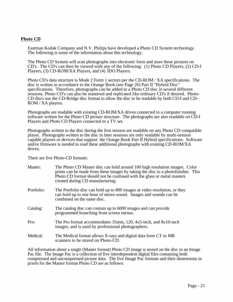
Photo CD
Eastman Kodak Company and N.V. Philips have developed a Photo CD System technology.The following is some of the information about this technology.
The Photo CD System will scan photographs into electronic form and store these pictures onCD's. The CD's can then be viewed with any of the following: (1) Photo CD Players, (2) CD-IPlayers, (3) CD-ROM/XA Players, and (4) 3DO Players.
Photo CD's data structure is Mode 2 Form 1 sectors per the CD-ROM / XA specifications. Thedisc is written in accordance to the Orange Book (see Page 26) Part II "Hybrid Disc"specifications. Therefore, photographs can be added to a Photo CD disc in several differentsessions. Photo CD's can also be mastered and replicated like ordinary CD's if desired. Photo-CD discs use the CD-Bridge disc format to allow the disc to be readable by both CD-I and CD-ROM / XA players.
Photographs are readable with existing CD-ROM/XA drives connected to a computer runningsoftware written for the Photo CD picture structure. The photographs are also readable on CD-IPlayers and Photo CD Players connected to a TV set.
Photographs written to the disc during the first session are readable on any Photo CD compatibleplayer. Photographs written to the disc in later sessions are only readable by multi-sessioncapable players or devices that support the Orange Book Part II Hybrid specifications. Softwareand/or firmware is needed to read these additional photographs with existing CD-ROM/XAdrives.
There are five Photo-CD formats:
Master: The Photo CD Master disc can hold around 100 high resolution images. Color prints can be made from these images by taking the disc to a photofinisher. ThisPhoto CD format should not be confused with the glass or metal masterscreated during CD manufacturing.
Portfolio: The Portfolio disc can hold up to 800 images at video resolution, or they can hold up to one hour of stereo sound. Images and sounds can be combined on the same disc.
Catalog: The catalog disc can contain up to 6000 images and can provide programmed branching from screen menus.
Pro: The Pro format accommodates 35mm, 120, 4x5-inch, and 8x10-inch images, and is used by professional photographers.
Medical: The Medical format allows X-rays and digital data from CT or MR scanners to be stored on Photo-CD.
All information about a single (Master format) Photo CD image is stored on the disc in an ImagePac file. The Image Pac is a collection of five interdependent digital files containing bothcompressed and uncompressed picture data. The five Image Pac formats and their dimensions inpixels for the Master format Photo CD are as follows:
Page - 21

Image Pac Formats and Their Dimensions in Pixels for the Master Format Photo CD
Name Height Width General Description Approximate File Size(Truecolor, Uncompressed)
Base/16 128 192 Thumbnail 48KB 78KBBase/4 256 384 Low Res. TV 171KB 294KBBase 512 768 High Res. or Zoomed TV
Image or VGA Monitor732KB 1,158KB
Base*4 1,024 768 HD-TV 3,078KB 4,614KBBase*16 2,048 3,072 High Res. HD-TV or 35mm
Quality13,533KB 18,438KB
For more information about Photo-CD, please call Eastman Kodak at 1-800-242-2424 extension51.
Page - 22
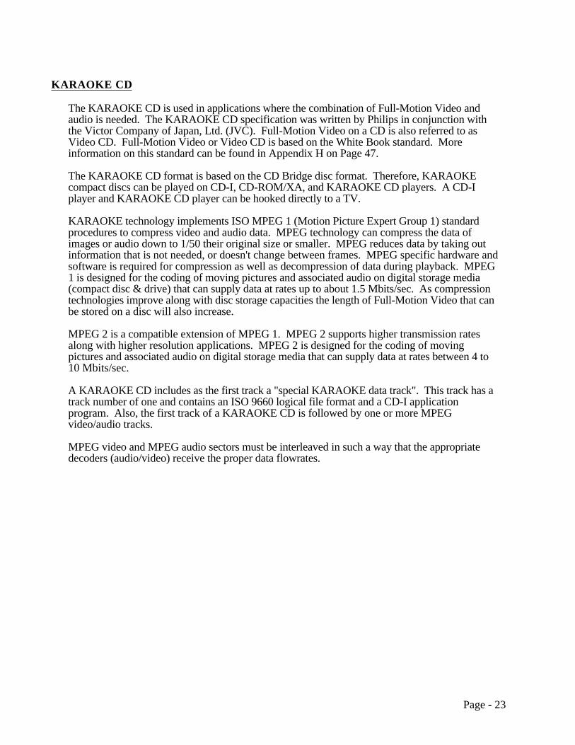
KARAOKE CD
The KARAOKE CD is used in applications where the combination of Full-Motion Video andaudio is needed. The KARAOKE CD specification was written by Philips in conjunction withthe Victor Company of Japan, Ltd. (JVC). Full-Motion Video on a CD is also referred to asVideo CD. Full-Motion Video or Video CD is based on the White Book standard. Moreinformation on this standard can be found in Appendix H on Page 47.
The KARAOKE CD format is based on the CD Bridge disc format. Therefore, KARAOKEcompact discs can be played on CD-I, CD-ROM/XA, and KARAOKE CD players. A CD-Iplayer and KARAOKE CD player can be hooked directly to a TV.
KARAOKE technology implements ISO MPEG 1 (Motion Picture Expert Group 1) standardprocedures to compress video and audio data. MPEG technology can compress the data ofimages or audio down to 1/50 their original size or smaller. MPEG reduces data by taking outinformation that is not needed, or doesn't change between frames. MPEG specific hardware andsoftware is required for compression as well as decompression of data during playback. MPEG1 is designed for the coding of moving pictures and associated audio on digital storage media(compact disc & drive) that can supply data at rates up to about 1.5 Mbits/sec. As compressiontechnologies improve along with disc storage capacities the length of Full-Motion Video that canbe stored on a disc will also increase.
MPEG 2 is a compatible extension of MPEG 1. MPEG 2 supports higher transmission ratesalong with higher resolution applications. MPEG 2 is designed for the coding of movingpictures and associated audio on digital storage media that can supply data at rates between 4 to10 Mbits/sec.
A KARAOKE CD includes as the first track a "special KARAOKE data track". This track has atrack number of one and contains an ISO 9660 logical file format and a CD-I applicationprogram. Also, the first track of a KARAOKE CD is followed by one or more MPEGvideo/audio tracks.
MPEG video and MPEG audio sectors must be interleaved in such a way that the appropriatedecoders (audio/video) receive the proper data flowrates.
Page - 23
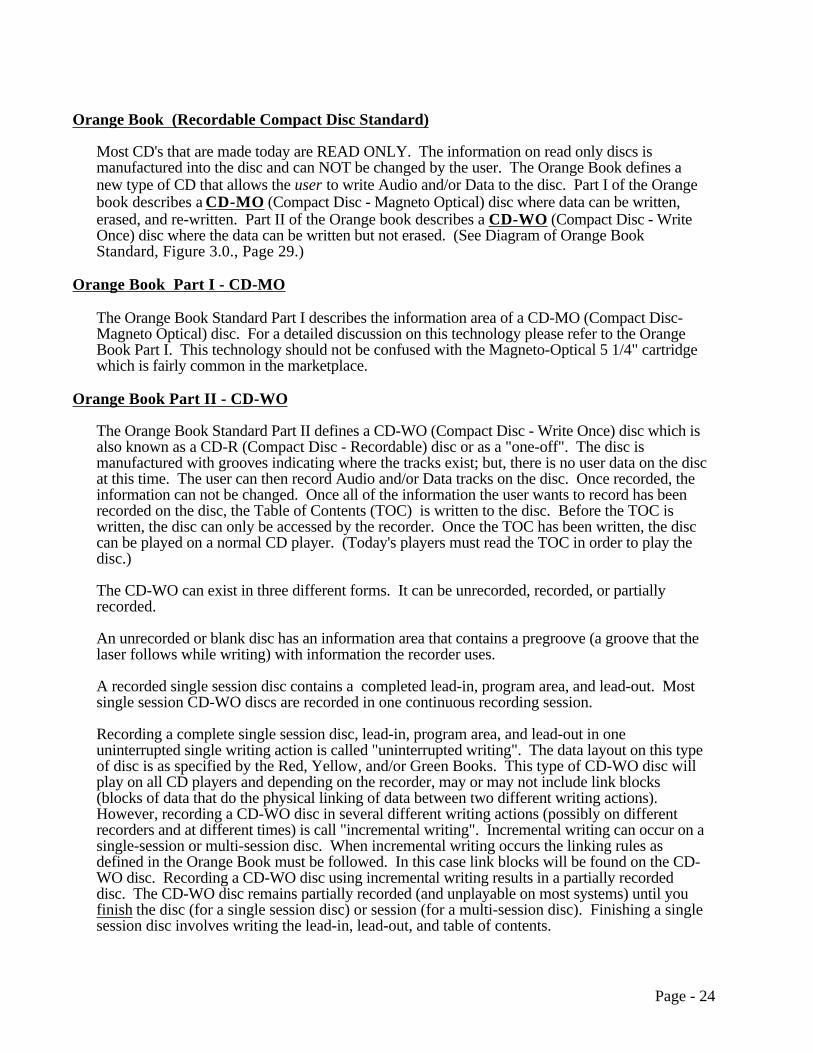
Orange Book (Recordable Compact Disc Standard)
Most CD's that are made today are READ ONLY. The information on read only discs ismanufactured into the disc and can NOT be changed by the user. The Orange Book defines anew type of CD that allows the user to write Audio and/or Data to the disc. Part I of the Orangebook describes a CD-MO (Compact Disc - Magneto Optical) disc where data can be written,erased, and re-written. Part II of the Orange book describes a CD-WO (Compact Disc - WriteOnce) disc where the data can be written but not erased. (See Diagram of Orange BookStandard, Figure 3.0., Page 29.)
Orange Book Part I - CD-MO
The Orange Book Standard Part I describes the information area of a CD-MO (Compact Disc-Magneto Optical) disc. For a detailed discussion on this technology please refer to the OrangeBook Part I. This technology should not be confused with the Magneto-Optical 5 1/4" cartridgewhich is fairly common in the marketplace.
Orange Book Part II - CD-WO
The Orange Book Standard Part II defines a CD-WO (Compact Disc - Write Once) disc which isalso known as a CD-R (Compact Disc - Recordable) disc or as a "one-off". The disc ismanufactured with grooves indicating where the tracks exist; but, there is no user data on the discat this time. The user can then record Audio and/or Data tracks on the disc. Once recorded, theinformation can not be changed. Once all of the information the user wants to record has beenrecorded on the disc, the Table of Contents (TOC) is written to the disc. Before the TOC iswritten, the disc can only be accessed by the recorder. Once the TOC has been written, the disccan be played on a normal CD player. (Today's players must read the TOC in order to play thedisc.)
The CD-WO can exist in three different forms. It can be unrecorded, recorded, or partiallyrecorded.
An unrecorded or blank disc has an information area that contains a pregroove (a groove that thelaser follows while writing) with information the recorder uses.
A recorded single session disc contains a completed lead-in, program area, and lead-out. Mostsingle session CD-WO discs are recorded in one continuous recording session.
Recording a complete single session disc, lead-in, program area, and lead-out in oneuninterrupted single writing action is called "uninterrupted writing". The data layout on this typeof disc is as specified by the Red, Yellow, and/or Green Books. This type of CD-WO disc willplay on all CD players and depending on the recorder, may or may not include link blocks(blocks of data that do the physical linking of data between two different writing actions).However, recording a CD-WO disc in several different writing actions (possibly on differentrecorders and at different times) is call "incremental writing". Incremental writing can occur on asingle-session or multi-session disc. When incremental writing occurs the linking rules asdefined in the Orange Book must be followed. In this case link blocks will be found on the CD-WO disc. Recording a CD-WO disc using incremental writing results in a partially recordeddisc. The CD-WO disc remains partially recorded (and unplayable on most systems) until youfinish the disc (for a single session disc) or session (for a multi-session disc). Finishing a singlesession disc involves writing the lead-in, lead-out, and table of contents.
Page - 24

The following two diagrams illustrate the difference between "uninterrupted writing" and"incremental writing" for a single-session disc:
Lead-in Lead-outProgram Area
Lead-in Lead-out
Link Blocks
WritingActionOne
WritingActionTwo
WritingActionThree
Program Area
"Uninterrupted Writing" without link blocksSingle-Session Disc
"Incremental Writing" with link blocks (finished)Single-Session Disc
There are basically two different types of recorders on the market today:
Yellow Book Recorder: This recorder can only record discs using uninterrupted orcontinuous writing. This recorder can not record a multi-session disc. Therefore, this recorder can only record a singlesession disc. Also, this recorder does not generate link blocks.
Orange Book Recorder: This recorder has additional hardware and software that allows forthe recording of discs using either uninterrupted or interrupted writing. Therefore, this recorder can record a single-session or multi-session disc. Also, this recorder generates link blocks.
A single-session disc has only one lead-in area, program area, and lead-out area. The programarea on this type of disc can either be written all at once (uninterrupted writing) or it can bewritten at different times (incremental writing) during different writing actions. Writing atdifferent times within a single program area does not make the disc a multi-session disc. Adiagram of a single-session disc is shown below:
Page - 25

Program Area(Incremental or Uninterrupted writing)
LeadIn
LeadOut
Single-Session Disc
A multi-session disc has more than one lead-in area, program area, and lead-out area. Theprogram areas on this type of disc can either be written all at once (uninterrupted writing) or theycan be written at different times (incremental writing) during different writing actions. One of theadvantages of this type of disc is that additional sessions/data can be added at different timeswhen needed. A good example of this is adding more photo's to a Photo CD disc.
Having multiple lead-in, program, and lead-out areas is what makes a disc a multi-session disc.A diagram of a multi-session disc is shown below.
Session 1 Session 2
Pre-mastered Areaor
Pre-Recorded AreaRecordable Area
Program Area(Incremental or Uninterrupted writing)
LeadIn
LeadOut
Multi-Session or Hybrid Disc
LeadIn
LeadOut
........
Note: Each session writes a TOC in the Lead In area for that session.Link Blocks are not shown in the above diagram to simplify the illustration.
Program Area(Incremental or Uninterruptedwriting)
The multi-session disc is defined in the Orange Book Part II. This type of disc is also known as a"Hybrid Disc". This disc contains two types of areas: (1) Pre-recorded Area and (2) RecordableAreas. The Pre-recorded area is a READ ONLY area where the information has beenmanufactured or recorded into the disc. (This area is written per the Red, Yellow, and/or Greenbook specifications, and can be played on any CD-Player.) The Recordable Areas are whereadditional recordings can be made in one or more sessions. Each recording session will write athree part area consisting of Lead In, Program Area, and Lead Out. Once information is writtento the disc, it can NOT be changed. Only the first session on the disc is readable by today's CD-Players, additional software will be needed to read the additional sessions.
When a hybrid disc has a pre-recorded area with user information, it is basically a finalized orfinished, recorded disc as described for a single-session disc above. However, a hybrid dischas additional recording possibility outside of the pre-recorded area of the disc.
CD-ROM players are read only players and can NOT record a CD-WO disc.
Page - 26

Orange Book
Part ICD-MO
Part IICD-WO
Rewriteable
PremasteredCD-ROM Area
+Rewriteable
Area
100%Rewriteable
Area
Diagram of Orange Book Standard
Regular CD-Player can NOT read thisdisc.
Write Once
RegularCD-WO
HybridCD-WO
MO = Magneto OpticalTOC = Table of Contents
Regular CD-Playercan only read thePremastered areaon this disc.
Regular CD-Player can read this discafter the last recordingis made and the TOC has been written to the disc.
Regular CD-Player can ONLY read thefirst recordingsession on this disc.With new softwareshould be able to read additionalrecorded sessions.
Write TOC after lastrecording. Disc hasone TOC.
A TOC is written during each recordingsession. Disc will havemultiple TOC's, one foreach recording session.
Photo-CD
CD-Audio, CD-ROM, and CD-WO discs are read by changes in reflectivity. However, CD-MO discs are read by the changes in the polarization direction of the reflected laser beam. The Optional Premastered area on a CD-MO is read by changes in reflectivity.
Figure 3.0
Page - 27
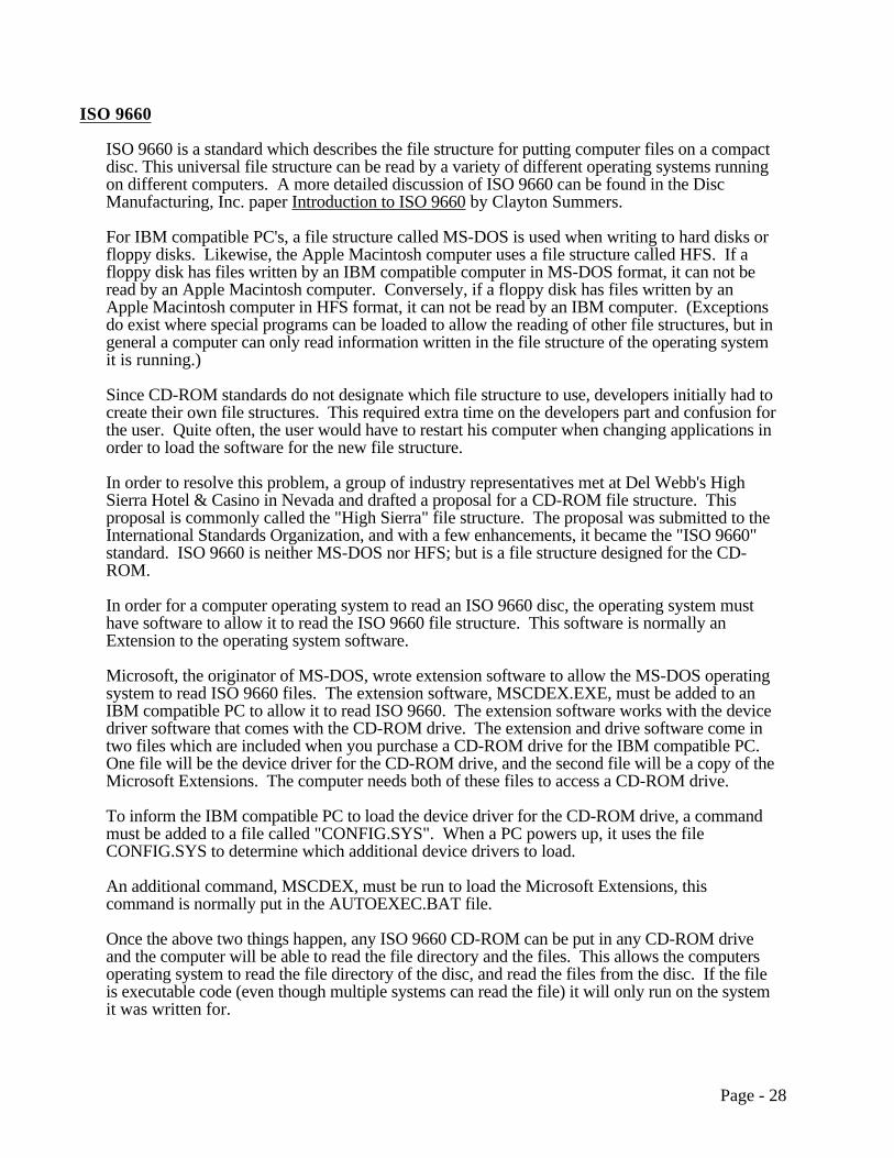
ISO 9660
ISO 9660 is a standard which describes the file structure for putting computer files on a compactdisc. This universal file structure can be read by a variety of different operating systems runningon different computers. A more detailed discussion of ISO 9660 can be found in the DiscManufacturing, Inc. paper Introduction to ISO 9660 by Clayton Summers.
For IBM compatible PC's, a file structure called MS-DOS is used when writing to hard disks orfloppy disks. Likewise, the Apple Macintosh computer uses a file structure called HFS. If afloppy disk has files written by an IBM compatible computer in MS-DOS format, it can not beread by an Apple Macintosh computer. Conversely, if a floppy disk has files written by anApple Macintosh computer in HFS format, it can not be read by an IBM computer. (Exceptionsdo exist where special programs can be loaded to allow the reading of other file structures, but ingeneral a computer can only read information written in the file structure of the operating systemit is running.)
Since CD-ROM standards do not designate which file structure to use, developers initially had tocreate their own file structures. This required extra time on the developers part and confusion forthe user. Quite often, the user would have to restart his computer when changing applications inorder to load the software for the new file structure.
In order to resolve this problem, a group of industry representatives met at Del Webb's HighSierra Hotel & Casino in Nevada and drafted a proposal for a CD-ROM file structure. Thisproposal is commonly called the "High Sierra" file structure. The proposal was submitted to theInternational Standards Organization, and with a few enhancements, it became the "ISO 9660"standard. ISO 9660 is neither MS-DOS nor HFS; but is a file structure designed for the CD-ROM.
In order for a computer operating system to read an ISO 9660 disc, the operating system musthave software to allow it to read the ISO 9660 file structure. This software is normally anExtension to the operating system software.
Microsoft, the originator of MS-DOS, wrote extension software to allow the MS-DOS operatingsystem to read ISO 9660 files. The extension software, MSCDEX.EXE, must be added to anIBM compatible PC to allow it to read ISO 9660. The extension software works with the devicedriver software that comes with the CD-ROM drive. The extension and drive software come intwo files which are included when you purchase a CD-ROM drive for the IBM compatible PC.One file will be the device driver for the CD-ROM drive, and the second file will be a copy of theMicrosoft Extensions. The computer needs both of these files to access a CD-ROM drive.
To inform the IBM compatible PC to load the device driver for the CD-ROM drive, a commandmust be added to a file called "CONFIG.SYS". When a PC powers up, it uses the fileCONFIG.SYS to determine which additional device drivers to load.
An additional command, MSCDEX, must be run to load the Microsoft Extensions, thiscommand is normally put in the AUTOEXEC.BAT file.
Once the above two things happen, any ISO 9660 CD-ROM can be put in any CD-ROM driveand the computer will be able to read the file directory and the files. This allows the computersoperating system to read the file directory of the disc, and read the files from the disc. If the fileis executable code (even though multiple systems can read the file) it will only run on the systemit was written for.
Page - 28

Similarly, Apple has written the software to allow ISO 9660 discs to be read from an AppleComputer, and UNIX vendors have written the software to allow ISO 9660 discs to be readfrom UNIX systems.
By writing applications designed to work with ISO 9660 discs, the applications developer doesnot have to write the software to access the CD-ROM, he can use the software written to accessthe ISO 9660 file structure. Because each application is using the same software, the computerdoes not have to be restarted when the user changes applications.
In addition to the above benefit, the ISO 9660 standard allows multiple types of computers toaccess the same files.
Files on a CD-ROM disc in the ISO 9660 format can be read on IBM compatible computers,Apple Computers, and UNIX Systems. This allows a software company to make one disc thatcan be run on all three systems. For example, a disc could be made with the following 5 files(these are fictitious filenames):
IBMPROG (executable program for MS-DOS)MACPROG (executable program for Apple)UNIXPROG (executable program for UNIX)DATA1 (Data for above executable programs)DATA2 (Data for above executable programs)
Assuming the file IBMPROG is a program for the IBM PC that uses the data files DATA1 andDATA2; the file MACPROG is a program for the Apple MAC that uses the data files DATA1 andDATA2; and the file UNIXPROG is a program for a UNIX based machine that uses the datafiles DATA1 and DATA2.
A PC running MS-DOS with Microsoft Extensions will be able to access all 5 files on this disc.The PC can execute the program IBMPROG and access the two data files, DATA1 and DATA2.This allows the PC to run the application. Even though the user can access the programs,MACPROG and UNIXPROG; the user would not be able to run these two programs becausethey are written to execute under a different operating system.
An Apple computer can also access all 5 of the files. The Apple computer can run the programMACPROG, giving the user access to the application and the two data files. Notice that theApple program MACPROG is accessing the same two data files, so the data only has to bewritten on the disc once. The files, IBMPROG and UNIXPROG are written to be executed onother computers and will not run correctly on the Apple.
Likewise, a user running UNIX can execute the UNIXPROG and have access to the applicationand the two data files.
In order to allow the file structure to be usable by IBM, Apple, and UNIX computers,ISO 9660 specifies (for all three interchange levels) that all filenames and directory namesmust meet the following conditions:
Capital letters "A-Z"Digits "0-9"Underscore "_"
The number of characters in the filename plus the extension can not exceed 30.
The directory name can not have extensions, or exceed 30 characters.
Page - 29

ISO 9660 level 1 interchange adds the following restrictions:
Filenames Maximum of 8 charactersFilename Extensions Maximum of 3 charactersDirectory Names Maximum of 8 characters (no
extension).
Each file shall consist of only one file section. This means that the files must be contiguous, or can not be recorded in interleave mode.
ISO 9660 level 2 interchange has only the following additional restriction:
Each file shall consist of only one file section. This means that the files must be contiguous, or can not be recorded in interleave mode.
ISO 9660 level 3 interchange has no additional restrictions.
Apple ISO 9660 Extensions:
The Macintosh's native file system, HFS, has many features to support its graphical userinterface that are not included in the ISO 9660 standard. By defining the Apple Extensions toISO 9660, Apple is able to define a way to add some of the above features using the system usefield of the ISO 9660 directory record. Therefore by using the Apple Extensions to ISO 9660one is able to retain some of the Macintosh look and feel; while keeping a disc in compliance withthe ISO 9660 standard.
Rock Ridge Interchange Protocol (RRIP):
The Rock Ridge Interchange Protocol was designed to allow users of POSIX and other UNIXlike systems to retain much of the directory information that is in the native file system. This isimportant because these systems use directory entries for much more than just pointing to files.Directory entries can point to other entries (symbolic links) or to device drivers that are linked toperipheral devices such as hard disks, tape drives and CD-ROM drives (device files). Thedirectory entry includes information that lets the system know what type of file it is dealing with,whether it is a regular file, directory, symbolic link, or device file. It also has informationregarding who has permission to read, write and execute each file. Most of these systems aremulti-user systems, and you would not want just anyone to be able to write to the device file thatcontains your operating system, because they could accidentally (or purposely?) erase the entireoperating system.
The Frankfurt Group Proposal:
The Frankfurt Group Proposal is a volume and file structure proposal that expands upon ISO9660. It is a superset of the ISO 9660 standard. In particular it is a volume and file structure thatnot only supports ISO 9660 CD-ROMS but also CD-WO (compact disc-write once) and CD-WOHybrid discs. CD-WO and CD-WO Hybrid are both part of the Orange Book (Page 26). TheFrankfurt Group Proposal helps to address the differences that arise due to an incrementallyrecorded disc.
Page - 30

The proposal defines two types of volume and file structures:
Type I:
Type I is the original ISO 9660 volume and file structure discussed at the beginning of thissection (ISO 9660). Type I is readable by any ISO 9660 compliant system.
Type II:
Type II is a superset follow-on of Type I. It allows for incremental recording of CD-WO as wellas updates to an existing CD-WO volume.
Page - 31

Non ISO 9660
Although ISO 9660 discs provide universal access and a standard file structure for the files, notall CD-ROMS are in the ISO 9660 format.
Example 1: High Sierra
When the High Sierra proposal was issued, it took a period of time before the ISO committeeissued the ISO 9660 standard. In the meantime, several applications came out in the High Sierraproposal format. To date, some applications have still not converted over to ISO 9660.
Microsoft Extensions Version 1.0 was written to work with the High Sierra proposal. When theISO 9660 standard was issued, Microsoft updated the software to Version 2.0. Anyone whostill has a copy of Microsoft Extensions Version 1.0 or 1.1 should upgrade to version 2.0 orhigher, because version 1.0 CAN NOT read ISO 9660 discs. (To get an updated copy ofMicrosoft Extensions, contact the company you purchased your CD-ROM drive from.)
Example 2: HFS
Apple has written drivers to allow the Apple Macintosh computer to read CD-ROM in any ofthree formats: ISO 9660, High Sierra, and HFS. When the CD-ROMS is being produced to runonly on Macintosh computers, some developers prefer to use the HFS structure instead of theISO 9660 structure. This gives them the standard Macintosh file naming characteristics andmaintains the desktop "look and feel".
Example 3: Custom File Formats
Some discs are still being written in other file formats either because they have not converted toISO 9660 or they are using other operating system formats.
In general, most discs are being made in ISO 9660.
Page - 32

Additional Technologies
3DO
The 3DO Company has introduced the 3DO Interactive Multiplayer which connects to a TV. The3DO player is a advanced multimedia player that produces high level graphics and real-timeinteractive performance. The 3DO player is capable of playing several different digital formatsincluding CD-Digital Audio, Kodak's Photo CD and CD+G. With an optional adapter the playerwill allow for the support of Full-Motion Video (FMV)/Video CD.
The 3DO company has selected a RISC 32-bit processor for its Interactive Multiplayer. The 3DOplayer incorporates a double speed CD-ROM (XA capable) drive.
DVI
DVI is a Compression / Decompression chip set that plays audio and video from files on a HardDisk, Floppy Disk, and/or CD-ROM disc. If the storage medium is CD-ROM for the files, thedisc should be in the ISO 9660 format.
A DVI disc is a regular Mode 1 CD-ROM as described in the first part of this paper. Thecomputer must have DVI boards to take the data from the CD-ROM and decompress it to normalvideo and audio signals.
CDTV
A CDTV disc is a Mode 1 CD-ROM as described in the first part of this paper. Commodore hasdecided to use ISO 9660 interchange level 2 to allow filenames up to 30 characters. These discsare designed to play only on Commodore equipment. (These long filenames can NOT beaccessed by a IBM compatible computer. IBM compatible computers running MicrosoftExtensions can only read ISO 9660 interchange level 1) CDTV discs are also using lower caseletters, which do not conform to ISO 9660.
Page - 33

Where To Get Additional Information
For additional information on the Red Book, Yellow Book, or ISO 9660 standard, contact:
American National Standards Institute1430 BroadwayNew York, NY 10018Sales Department: (212) 642-4900
Red Book : CEI IEC 908
Yellow Book: ISO 10149:1989
ISO9660: ISO 9660:1988
For additional information on the Green Book (CD-I), contact:
CD-I Association of North America11111 Santa Monica, Suite 700Los Angeles, CA 90025Phone: (310) 444-6613FAX: (310) 479-5937
For additional information on the Orange Book, contact:
Mr. Burt GallPhilips Consumer ElectronicsCoordination OfficeOptical and Magnetic Media SystemsPO Box 800025600 JBEindhoven, The NetherlandsPhone: 011-31-40-736409FAX: 011-31-40-732113
For additional information on mastering and replicating Compact Discs, contact:
Disc Manufacturing, Inc.1409 Foulk Road, Suite 102Wilmington, DE 19803Phone: 1-800-433-DISC or 1-302-479-2500FAX: 1-302-479-2527Applelink: DMI.CD
Page - 34

Appendix A: Control Bytes (Subcode Channels P through W):
Up to this point, this paper has been giving details on how the basic 2352 byte area is laid out.In addition to the 2352 bytes of information included in each sector there is 98 bytes of datacalled the Control Bytes.
These control bytes are produced by summing together 98 separate 8-bit fields. The 8-bits arecalled a control byte because the first two bits contain timing information that is used by audioplayers to position the drive head. The remaining 6 bits are available for User Information (seesubcode channels R-W section).
We have been talking about a 2352 byte area, where each byte contains 8 bits. In order todiscuss the subchannels that make up the control bytes, we must talk about bits.
The 8 bits in a control byte are named P, Q, R, S, T, U, V, W; where each bit represents asubcode channel. For example, if you look at the first bit of every control byte, this stream ofbits is called the "P" subchannel. Likewise, all of the second bits in every control byte are calledthe "Q" subchannel. (See the following sections for information regarding how the subchannelsare used.)
Breakdown of a Control Byte:
"P" Sub-channel (1 bit)
"Q" Sub-channel (1 bit)
"R-W" Sub-channels (6 bit words)
Control Byte (8 bits)PQRSTUVW
RSTUVWPQ
Subcode Channel P
The "P" subchannel contains a flag that signals where the music or data starts on a track
Subcode Channel Q
The "Q" subchannel contains the running times from both the beginning of the disc and from thebeginning of the current track. Audio players use this information to display the music playingtime.
98 control bytes, Layout for bit position "Q":
72 Bits 16 Bits2 4 4
2 bits - part of the synchronization for the Control Bytes 4 bits - control flags defining what type of information is in this CD track. 4 bits - control flags for the following 72 bits of data72 bits - Q sub-channel data
(During the disc Lead In, the Q channel data contains the discs Table of
Page - 35
contents. For the rest of the disc, the Q channel data contains the current playing time. Both track relative time and total disc time.)
16 bits - CRCC (Error Detection Bits) (Cyclic Redundancy Check Code)
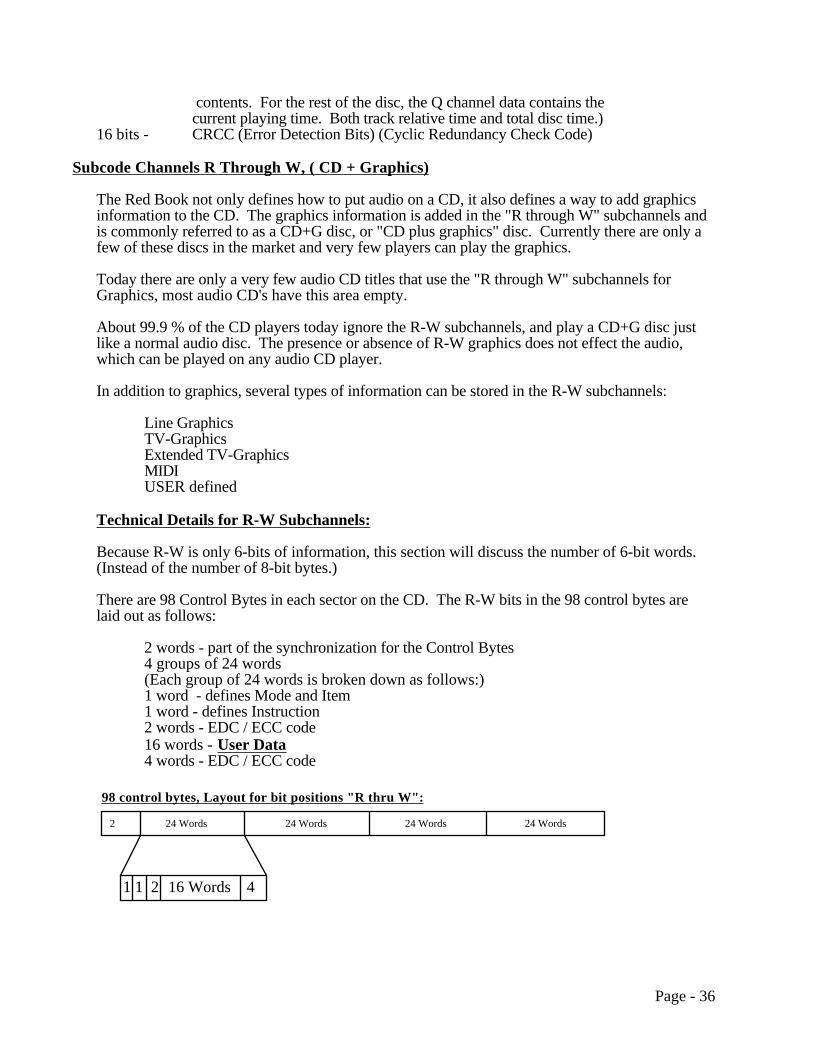
Subcode Channels R Through W, ( CD + Graphics)
The Red Book not only defines how to put audio on a CD, it also defines a way to add graphicsinformation to the CD. The graphics information is added in the "R through W" subchannels andis commonly referred to as a CD+G disc, or "CD plus graphics" disc. Currently there are only afew of these discs in the market and very few players can play the graphics.
Today there are only a very few audio CD titles that use the "R through W" subchannels forGraphics, most audio CD's have this area empty.
About 99.9 % of the CD players today ignore the R-W subchannels, and play a CD+G disc justlike a normal audio disc. The presence or absence of R-W graphics does not effect the audio,which can be played on any audio CD player.
In addition to graphics, several types of information can be stored in the R-W subchannels:
Line GraphicsTV-GraphicsExtended TV-GraphicsMIDIUSER defined
Technical Details for R-W Subchannels:
Because R-W is only 6-bits of information, this section will discuss the number of 6-bit words.(Instead of the number of 8-bit bytes.)
There are 98 Control Bytes in each sector on the CD. The R-W bits in the 98 control bytes arelaid out as follows:
2 words - part of the synchronization for the Control Bytes4 groups of 24 words(Each group of 24 words is broken down as follows:)1 word - defines Mode and Item1 word - defines Instruction2 words - EDC / ECC code16 words - User Data4 words - EDC / ECC code
24 Words
98 control bytes, Layout for bit positions "R thru W":
24 Words 24 Words 24 Words2
1 1 2 16 Words 4
Page - 36

The Control Bytes are not protected by the same EDC / ECC code that protects the 2352 bytearea. A separate set of EDC / ECC code is generated and placed in the R-W subchannels asshown above.
R-W subcode can hold 64 6-bit words of User Data per sector.(16 words User Data per group) x (4 groups) = 64 words(CD-ROM Mode 1 can hold 2048 8-bit words (bytes) of User Data per sector.)
User Data can only be written to R-W subcode channels for Red Book tracks, (CD-DA tracks).The Yellow Book specifies that the R-W subcode channels will be zero for data tracks.
Page - 37

Appendix B: CD-Encoding Overhead:
The following example is for a 74 minute Red Book CD. This example is to inform the reader about the overheads associated with CD technology.
A 74 minute CD contains approximately 1.92 X 1010 bits of information encoded on the disc.This is approximately 2.4GB. So the first question one might ask is: Why can't I store 2.4GBworth of user data on the disk? The reason you can't is due to the amount of overhead associated with certain aspects of the disc. The technologies that make a CD very reliable like the error correction codeand the Eight to Fourteen Modulation also require information or data to perform their functions.
Eight to Fourteen Modulation is the process of converting every 8 bits of data to 14 bits of data for storageon the disc. This conversion helps facilitate the reading of data from the disc. When the data is read backfrom the disc it is converted back to 8 bits from 14 bits.
The data these technologies use reduces the overall storage capacity that remains for the user's data.
The following diagram shows the various parts of a CD and the % of the overall storage capabilityused by each:
User's Data
EFM (Eight to Fourteen Modulation)
Merging Bits
CIRC
Synchronization4.08%
Subcode1.36%
32.65%
33.67%
17.35%
10.88%
(Levels 1 &2)
It is amazing to note that of all the actual storable information on a disc, only around 30% can beused for the actual user's data. The rest is consumed by the error correction, EFM, MergingBits, Synchronization, and Subcode. The above example is for a Red Book CD which only has2 layers of error correction built in. A CD-ROM Mode 1 disc with the additional (3rd layer) oferror correction included would allow the user even less a percentage of the total disc for user
Page - 38

data. The amount of user data available on a Mode 1 disc would be around 28.43% for a 74minute disc.
However it should be mentioned that all of the above overheads serve very important roles inmaking the CD a very robust and flexible technology.
Page - 39

Appendix C: CD-I Ready Disc Layout:
The following diagram shows the layout of a CD-I Ready Disc.
Track #1 Index 0
Track #1 Index 1
Track #2 Index 0
Track #2 Index 1
Track #3 Index 0
Track #3 Index 1
Track #AA Index 1
30 seconds postgap, sector headers show mode 2Contains scrambled Headers and Sub-headers,but unscrambled CD-DA silence as data.
CD-I data sectors (per Green Book)sector headers show mode 2sectors scrambled per Green Book
120 second pregap (per CD-I Ready Specif icat ion)sectors of Red Book audio s i l ence
sectors o f f i r s t audio songcoded per Red Book (recommend start ing with 12 sectors ofaudio s i l ence )
sec tors o f second audio songcoded per Red Book (recommend start ing with 12 sectors ofaudio s i l ence )
sectors of th ird audio songcoded per Red Book (recommend start ing with 12 sectors ofaudio s i l ence )
2 seconds of pre message Part A, s tart ing at 00:00:00sector headers show mode 2sectors scrambled per Green Book
volume descriptors per the Green Book, s tart ing a t 0 0 : 0 2 : 1 6
30 seconds of pre message Part B
data
audiosong
audiosong
audiosong
Track #1 Pause
Optional: 2 second audio pause (per Red Book)sec tors o f audio s i l ence
Optional: 2 second audio pause (per Red Book)sec tors o f audio s i l ence
Page - 40
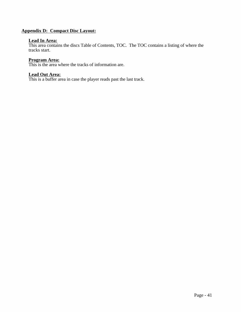
Appendix D: Compact Disc Layout:
Lead In Area:This area contains the discs Table of Contents, TOC. The TOC contains a listing of where thetracks start.
Program Area:This is the area where the tracks of information are.
Lead Out Area:This is a buffer area in case the player reads past the last track.
Page - 41

Appendix E: Playability Matrix:
The Playability Matrix below is provided for the readers information only. This matrix should beviewed as a very rough rule of thumb of "what type of disc will play on what type of player or computer". Information within this matrix should not be viewed as absolute or complete. It should be noted that almost any disc can play on any type of player if enough time is taken to write a "driver" or software to make a given disc format compatible.
Please check with the drive manufacturers and/or the companies that license the disc type or application to get the latest information concerning playability.
Playability Matrix
Types of Drives or PlayersDisc TypeorApplication
Comment/Examples
CD-ROMDrive&PC/DOS
CD-ROMDrive&MAC
CD-ROMDrive&UNIX
CD-IPlayer
3DOPlayer
PhotoCDPlayer
KaraokePlayer
CD-DAPlayerHomeStereo
CDTVPlayer
CD-I Disc Greenbook yesCD-I ReadyDisc
CD-DA& CD-I App
yes yes,Audioonly
Bridge Disc Photo CDKara. CD
yesXA drive
yesXA drive
yesXA drive
yes yes, ifPhotoCD
yes, ifPhotoCD
yes, ifKara. CD
Photo CDDisc
BridgeDisc, XA
yesXA drive
yesXA drive
yesXA drive
yes yes yes
Karaoke CD Bridge Disc yesXA drive
yesXA drive
yesXA drive
yes yes
MixedMode Disc
Mode 1Data &CD-DA
yesDOSData
yesMACData
yesUNIXData
yes yesAudioOnly
yes yesAudioOnly
3DO Disc yesCD-DADisc
Red Book yesAdd. SW
yesAdd. SW
yesAdd. SW
yes yes yes yes
CD-ROMXA Disc
yesXA drive
yesXA drive
yesXA drive
yes, ifBridgeDisc
yes, if3DODisc
yes, ifPhotoCD
yes
ISO 9660Interch. 1Interch. 2Interch. 3
Recomd. forPC&DOSApp./UNIXXA Disc
yes
yesXA drive
yesyesXA drive
yesyesXA drive
HFS Disc MAC yesHybrid Disc ISO 9660 &
HFS Imageyes yes
DVI Disc Comp.must haveDVI Adap.
yes
CDTV Disc Commodore yesCD-R DiscCD-WO
Orange Bk.many types
yes yes yes yes yes yes yes yes yes
CD+G Disc Graphics& CD-DA
yes yesAudioOnly
yes
MPEG(FMV)Video CD
Full MotionVideo
yes,XA driveMPEGchips
yes,XA driveMPEGchips
yes,XA driveMPEGchips
yes,needsFMVadapter
yes,withproperadapter
yes, ifKaraokeCD
yes,NimbusVideoCDW/Adptr.
Page - 42

Appendix F: Transition Between Tracks (Pre-gap, Post-gap, and Pause):
The areas of a disc that help in the transition between tracks of data (same or different mode) andaudio are called Pre-gap, Post-gap, and Pause. Please consult the Yellow Book specificationsfor details concerning Pre-gap, Post-gap, and Pause. The following information should beviewed as general rules of thumb.
Pre-gap is the area on a disc (at least 2 seconds) that separates two different types of tracks. It consists of user data that is all zeros. Pre-gap can occur between the end of lead-in and the beginning of the data track. It can also occur between two tracks of data that are different modes(mode 1 and mode 2, for example).
Post-gap is the area on a disc (at least 2 seconds) that follows a data track. It consists of user data that is all zeros. If the last track on a disc is a data track there will be a Post-gap appended toit. Also if a data track is followed by an audio track (mixed mode disc) then a Post-gap will be appended to that data track.
Pause is the area on disc (usually 2 seconds) that precedes audio tracks (between index 0 and index 1). The contents of a pause depends on the contents of the tracks on either side of it according to the Pre-gap rule. A pause may be digital audio silence or it could be a Pre-gap.
The following diagram summarizes the above discussions:
Lead-in Pre-gap Data (Tracks)
Data(Track N) Pre-gap Data (Different Mode)
(Track N+1)
Audio(Track N)
Pre-gap Data(Track N+1)
Post-gap Lead-out
Data(Track N)
Post-gap Audio(Track N+1)
Audio(Track N)
Pause Audio(Track N+1)
Data(Track N)
Data (Same Mode)(Track N+1)
Pause
Transition Between Adjacent Tracks
(Program Area)
Complete Compact Disc Layout:
Transition Between Tracks Layouts:
Page - 43
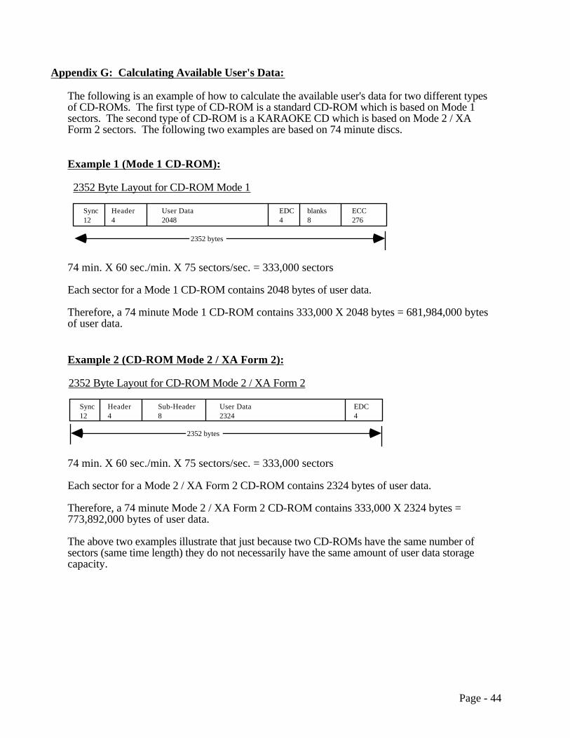
Appendix G: Calculating Available User's Data:
The following is an example of how to calculate the available user's data for two different types of CD-ROMs. The first type of CD-ROM is a standard CD-ROM which is based on Mode 1 sectors. The second type of CD-ROM is a KARAOKE CD which is based on Mode 2 / XA Form 2 sectors. The following two examples are based on 74 minute discs.
Example 1 (Mode 1 CD-ROM):
.Sync12
Header4
User Data2048
EDC4
ECC276
2352 Byte Layout for CD-ROM Mode 1
blanks8
2352 bytes
74 min. X 60 sec./min. X 75 sectors/sec. = 333,000 sectors
Each sector for a Mode 1 CD-ROM contains 2048 bytes of user data.
Therefore, a 74 minute Mode 1 CD-ROM contains 333,000 X 2048 bytes = 681,984,000 bytes of user data.
Example 2 (CD-ROM Mode 2 / XA Form 2):
Sync12
Header4
Sub-Header8
User Data2324
EDC4
2352 Byte Layout for CD-ROM Mode 2 / XA Form 2
2352 bytes
74 min. X 60 sec./min. X 75 sectors/sec. = 333,000 sectors
Each sector for a Mode 2 / XA Form 2 CD-ROM contains 2324 bytes of user data.
Therefore, a 74 minute Mode 2 / XA Form 2 CD-ROM contains 333,000 X 2324 bytes = 773,892,000 bytes of user data.
The above two examples illustrate that just because two CD-ROMs have the same number of sectors (same time length) they do not necessarily have the same amount of user data storage capacity.
Page - 44

Appendix H: Full-Motion Video:
White Book/Video CD
Video CD (Renamed from KARAOKE CD because of the wider application use than justKARAOKE machines of Full-Motion Video.) is used in applications where the combination ofFull-Motion Video and audio is needed. The Video CD format is also known as the "WhiteBook". This format was written by Philips in conjunction with the Victor Company of Japan,Ltd. (JVC). This format is also supported by Sony and Matsushita.
The Video CD format is based on the CD Bridge disc format. Therefore, Video CD compactdiscs can be played on CD-I, CD-ROM/XA, and KARAOKE CD players. A CD-I player andKARAOKE CD player can be hooked directly to a TV.
Video CD technology implements ISO MPEG 1 (Motion Picture Expert Group 1) standardprocedures to compress video and audio data. MPEG technology can compress the data ofimages or audio down to 1/50 their original size or smaller. MPEG reduces data by taking outinformation that is not needed, or doesn't change between frames. MPEG specific hardware andsoftware is required for compression as well as decompression of data during playback. MPEG1 is designed for the coding of moving pictures and associated audio on digital storage media(compact disc & drive) that can supply data at rates up to about 1.5 Mbits/sec. As compressiontechnologies improve along with disc storage capacities the length of Full-Motion Video that canbe stored on a disc will also increase.
MPEG 2 is a compatible extension of MPEG 1. MPEG 2 supports higher transmission ratesalong with higher resolution applications. MPEG 2 is designed for the coding of movingpictures and associated audio on digital storage media that can supply data at rates between 4 to10 Mbits/sec.
MPEG video and MPEG audio sectors must be interleaved in such a way that the appropriatedecoders (audio/video) receive the proper data flowrates.
Nimbus Technology & Engineering/Video CD
Nimbus Technology & Engineering has also developed a Video CD technology different than theone based on the White Book discussed above.
The Nimbus Video CD and the White Book Video CD both implement the MPEG 1 technologydiscussed above. However, the overall technologies are different. The Nimbus Video CDconforms to the digital audio Red Book standard. Therefore, Nimbus Video CD's can be playedon a standard audio CD player that has SPDIF digital output along with a special decoder(connected to the CD player and a TV) available from Nimbus.
The White Book Video CD's are encoded like CD-ROMS and incorporate XA technology. TheCD-ROM specifications require a data "flag" (in the control field of the Q subchannel) thatprevents (some) audio CD players from playing the data and possibly damaging the speakers.
Therefore the difference between the two technologies is whether or not the data bit is set in theQ-subchannel.
Page - 45

Appendix I: Technical Breakdown of how sectors are put on a CD:
The following two pages show a diagram of how sectors are put on a CD.
Page - 46

Expanded View ofSector Layout.User Data is Sent to Manufacturer on Image Tapes.
SECTOR: 2352 Bytes (Mode 1)
Sync12 bytes
Header4 bytes
User Data2048 bytes
EDC4 bytes
Zeros8 bytes
P parity172 bytes
Q parity104 bytes
Sync
SCRAMBLER
Sync
2340 bytes
2340 scrambled bytes
Sector 95
Sector 96 Sector 97Sector 94
Scramble DataNOT Sync
Map to 98 Frames.24 Bytes in Each Frame.
1 24ƒ2 S95 ƒ98 S95 ƒ1 S96
1 24ƒ2 S95
Map to F1 Frames.Swap MSB with LSB ofeach 16 Bit Word.
ƒ1 S95
ƒ1 S95
24ƒ2 S95 ƒ3 S95
1 24ƒ1 S95
Displace and InterleaveF1 Frames. Each ArrowAssosiated with 2 Bytes.
1
Pass Through 0 to 108 Frame Delay Lines.
1 24ƒ3 S95 ƒ98 S95 ƒ1 S96
ƒ98 S95 ƒ1 S96
Pass Through C2 Encoder.Genrates 4 Bytes of Q Parity.
4 frame delay
1ƒ3 S95 ƒ4 S95 ƒ5 S95 ƒ6 S95
1ƒ7 S95
108 frame delay
C2 ENCODER
1ƒ3 S95 ƒ4 S95 ƒ5 S95
4 bytes Q Parity
Q Q Q Q
A
ƒ2 S95241
ƒ1 S95Q Q Q Q
No Delay
ƒ97 S95
Q Q Q Q
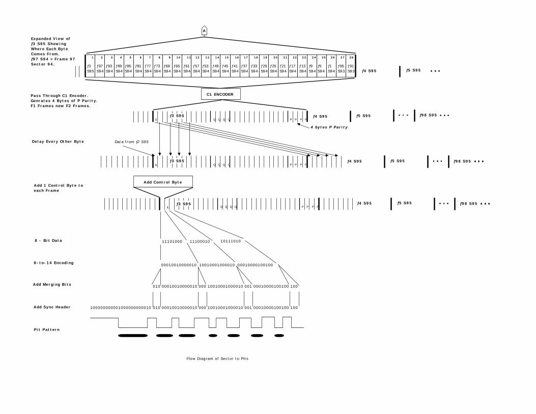
Expanded View ofƒ3 S95 ShowingWhere Each ByteComes From.ƒ97 S94 = Frame 97Sector 94.
Pass Through C1 Encoder.Genrates 4 Bytes of P Parity.F1 Frames now F2 Frames.
Delay Every Other Byte
Add 1 Control Byte to each Frame
8 - Bit Data
8-to-14 Encoding
Add Merging Bits
Add Sync Header
Pit Pattern
11101000 11100010 10111010
00010010000010 10010001000010 00010000100100
010 00010010000010 000 10010001000010 001 00010000100100 100
010 00010010000010 000 10010001000010 001 00010000100100 100100000000001000000000010
ƒ3S95
1
ƒ97S94
2
ƒ93S94
3
ƒ89S94
4
ƒ85S94
5
ƒ81S94
6
ƒ77S94
7
ƒ73S94
8
ƒ69S94
9
ƒ65S94
10
ƒ61S94
11
ƒ57S94
12
ƒ53S94
13
ƒ49S94
14
ƒ45S94
15
ƒ41S94
16
ƒ37S94
17
ƒ33S94
18
ƒ29S94
19
ƒ25S94
20
ƒ21S94
21
ƒ17S94
22
ƒ13S94
23
ƒ9S94
24
ƒ5S94
25
ƒ1S94
26
ƒ95S93
27
ƒ91S93
28
ƒ4 S95 ƒ5 S95
C1 ENCODER
4 bytes P Parity
1ƒ3 S95 ƒ4 S95 ƒ5 S95
Q Q Q Q P P P P
1ƒ3 S95 ƒ4 S95 ƒ5 S95 ƒ98 S95
Q Q Q Q P P P P
Data from ƒ2 S95
A
Add Control Byte
1ƒ3 S95 ƒ4 S95 ƒ5 S95
Q Q Q Q P P P Pƒ98 S95
ƒ98 S95
Flow Diagram of Sector to Pits