compact camera module testing equipment with a conversion lens · compact camera module testing...
TRANSCRIPT
Compact camera module testing equipment with
a conversion lens
Jui-Wen Pan* 1Institute of Photonic Systems, National Chiao Tung University, Tainan City 71150, Taiwan
2Biomedical Electronics Translational Research Center, National Chiao Tung University, Hsin-Chu City 30010, Taiwan
3Department of Medical Research, Chi Mei Medical Center, Tainan 71004, Taiwan
• Abstract: Modified testing equipment for adjusting the back focal length
of a compact camera module (CCM) is proposed. The advantages of this
modified testing equipment which includes a conversion lens are that it
saves on testing space, offers a smaller sized testing chart, as well as high
speed chart changing, and variable object distances. The modified testing
equipment can produce a test chart of 38.32 mm compared to an equivalent
testing chart of 5000 mm with the conventional testing equipment. At the
regular object distance of 2000 mm, both total track and testing chart size
for the modified test equipment were 8.3% that of the conventional testing
equipment. By using this testing equipment, the testing space can be shrunk
significantly.
©2012 Optical Society of America
OCIS codes: (080.3620) Lens system design; (080.2740) Geometric optical design; (080.3630)
Lenses.
References and Links
1. C. S. Liu and P. D. Lin, “A miniaturized low-power VCM actuator for auto-focusing applications,” Opt. Express
16(4), 2533–2540 (2008). 2. C. S. Liu and P. D. Lin, “Miniaturized auto-focusing VCM actuator with zero holding current,” Opt. Express
17(12), 9754–9763 (2009).
3. N. Sugiura and S. Morita, “Variable-focus liquid-filled optical lens,” Appl. Opt. 32(22), 4181–4186 (1993).
4. J. W. Pan, “The first order optics of novel testing equipment for compact camera module,” IODC (OSA 2010)
paper JMB25 (2010).
5. W. J. Smith, “Stops, apertures, pupils and diffraction,” in Modern Optical Engineering, 4th ed. (Mc-Graw Hill, 2008), pp. 182–183.
6. Largan Precision Co, Ltd. “Conventional compact camera module specification,”
http://www.largan.com.tw/html/product/product_cellphone_en.aspe 7. W. J. Smith, “Scanner/f-θ, laser disk and collimator lenses,” in Modern Lens Design, 2nd ed. (Mc-Graw Hill,
2005), pp. 561–571.
8. M. Laikin, “F-theta scan lenses,” in Lens Design, 4th ed. (CRC Press, 2007), 245–252. 9. R. E. Fischer, B. Tadic-Galeb, and P. R. Yoder, “Hardware design issue,” in Optical System Design, 2nd ed.
(Mc-Graw Hill, 2008), pp. 594–595.
10. G. C. Holst, “Sampling theory,” in Electro-Optical Imaging System Performance, 4th ed. (SPIE, 2006), pp 72–87.
11. B. Hayashida, “F-theta lens system for four-group construction,” U.S. patent 4400063 (Aug 23, 1983).
12. K. Fuse, “F-theta lens,” U.S. patent 6324015 (Nov 27, 2001) 13. W. J. Smith, “Optical computation,” in Modern Optical Engineering, 3rd ed. (McGraw- Hill, 2000), pp. 301–
346.
14. M. J. Kidger, “Principles of lens design,” in Fundamental Optical Design (Mc-Graw Hill, 2001), pp. 158–159.
15. M. J. Kidger, “Principles of lens design,” in Fundamental Optical Design (Mc-Graw Hill, 2001), pp. 150–151.
16. J. M. Geary, “Lens splitting,” in Introduction to Lens Design with Practical ZEMAX Examples (Willmann-Bell,
2001). 17. R. E. Fischer, B. Tadic-Galeb, and P. R. Yoder, “Hardware design issue,” in Optical System Design, 2nd ed.
(Mc-Graw Hill, 2008), pp. 675–677.
18. Omni Vision Technologies, Inc., http://www.ovt.com/ 19. W. J. Smith, “Stops, the practice of optical engineering,” in Modern Optical Engineering, 4th ed. (Mc-Graw Hill,
2008), pp. 620–622.
#160731 - $15.00 USD Received 3 Jan 2012; revised 9 Feb 2012; accepted 9 Feb 2012; published 17 Feb 2012(C) 2012 OSA 27 February 2012 / Vol. 20, No. 5 / OPTICS EXPRESS 5303
20. IEEE resolution target chart, Spring Master Source Book (Edmund Optics, 2011), p. 363.
1. Introduction
Small sized portable electronic devices such as mobile phones and personal digital assistants
(PDAs) are becoming common consumer electronic devices especially for the purposes of
time management and information communication. An essential element of these consumer
electronic products is comprised of the imaging device. In order to include the imaging device
in these devices, the imaging and sensing components are packaged into a compact size
module called the compact camera module (CCM). The CCM consists of complementary
metal-oxide-semiconductor (CMOS) sensors, a lens holder and a pick-up lens. The
characteristics of the CCM such as its low cost, compact volume and simple structure, allow it
to be widely applied in web cameras and mobile phones. However, the CCM is simple in
structure, so lacks a dynamic focus compensation mechanism, such as voice coil motor
(VCM) and liquid lens [1–3]. Thus, the accuracy of alignment between the pick-up lens and
imaging sensor becomes an important issue in its assembly.
The current method for testing the CCM assembly is to use a real testing chart to adjust
the back focal length of CCM as a compensator. A testing chart is localized in front of the
pick-up lens and then the image quality on the CMOS sensor is used to judge whether it was
assembled on the back focal plane of the pick-up lens. If the back focal length between the
CMOS sensor and pick-up lens cannot be assembled precisely, the image quality will be
blurred which impacts the yield during CCM mass production. Generally, the object distance
for the CCM in a mobile phone can vary from 200 mm to 5000 mm depending on the
application. In order to find the correct back focal length in conventional testing equipment,
the testing chart is moved along the normal direction of the CCM for assembly quality
examination. Thus the volume of conventional testing equipment needed is large and testing
chart fabrication cost expensive. The volume of testing equipment needed can be reduced by
the insertion of a folding mirror in the imaging path which can reduce the horizontal space.
However, there is a simultaneous increase in the vertical space because the total track of the
optical path for an image pick-up system remains constant under the conjugation relations
between an object and an image. In addition, the folding mirror also increases the equipment
cost and induced alignment issues in the mass examination process. In other words, the
conventional testing equipment still has the problem of possessing an overly large volume, an
aspect which needs to be improved.
In this study, the enables conversion lens is needed in order to shrink the testing
equipment to meet the size limitations of 120 mm × 100 mm × 250 mm. The conversion lens
was inserted into the testing equipment to produce an erect virtual image. The novel
conversion lens testing equipment possessed a short testing period and a compact size which
is also helpful to improve the mass production of CCMs. Moreover, the image quality,
resolution and distortion are almost the same as for traditional testing systems.
2. Design concept and specifications for the conversion lens
2. A. First order optics
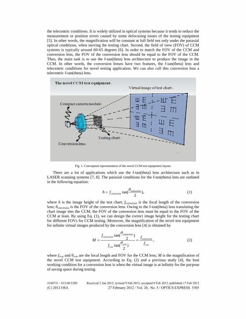
A conceptual representation of the novel CCM test equipment is shown in Fig. 1. The system
consists of a CCM, a conversion lens and a testing chart. The inclusion of the proposed
conversion lens allows a significant decrease in the volume of the testing system. The
conversion lens produces an erect virtual image which is used as the new testing chart for the
CCM module testing. The first order equations have been described in detail in a previous
publication [4]. According to the data, the conversion lens and CCM test lens have a first
order relationship, but the result is only a paraxial optics result. Moreover, the design
architecture is based on both telecentric lenses and f-tan(theta) lenses. Each feature offers
some advantages for CCM testing. First, there is an advantage for the lens architecture with
#160731 - $15.00 USD Received 3 Jan 2012; revised 9 Feb 2012; accepted 9 Feb 2012; published 17 Feb 2012(C) 2012 OSA 27 February 2012 / Vol. 20, No. 5 / OPTICS EXPRESS 5304
the telecentric conditions. It is widely utilized in optical systems because it tends to reduce the
measurement or position errors caused by some defocusing issues of the testing equipment
[5]. In other words, the magnification will be constant at full field not only under the paraxial
optical conditions, when moving the testing chart. Second, the field of view (FOV) of CCM
systems is typically around 60-65 degrees [6]. In order to match the FOV of the CCM and
conversion lens, the FOV of the conversion lens should be equal to the FOV of the CCM.
Then, the main task is to use the f-tan(theta) lens architecture to produce the image in the
CCM. In other words, the conversion lenses have two features, the f-tan(theta) lens and
telecentric conditions for novel testing application. We can also call this conversion lens a
telecentric f-tan(theta) lens.
Fig. 1. Conceptual representation of the novel CCM test equipment layout.
There are a lot of applications which use the f-tan(theta) lens architecture such as in
LASER scanning systems [7, 8]. The paraxial conditions for the f-tan(theta) lens are outlined
in the following equation:
tan( ),2
conversion
conversionh f
(1)
where h is the image height of the test chart; fconversion is the focal length of the conversion
lens; θconversion is the FOV of the conversion lens. Owing to the f-tan(theta) lens translating the
chart image into the CCM, the FOV of the conversion lens must be equal to the FOV of the
CCM at least. By using Eq. (1), we can design the correct image height for the testing chart
for different FOVs for CCM testing. Moreover, the magnification of the novel test equipment
for infinite virtual images produced by the conversion lens [4] is obtained by
tan( )2 ,
tan( )2
conversionconversion
conversion
ccm ccmccm
ff
Mf
f
(2)
where fccm and θccm are the focal length and FOV for the CCM lens; M is the magnification of
the novel CCM test equipment. According to Eq. (2) and a previous study [4], the best
working condition for a conversion lens is when the virtual image is at infinity for the purpose
of saving space during testing.
#160731 - $15.00 USD Received 3 Jan 2012; revised 9 Feb 2012; accepted 9 Feb 2012; published 17 Feb 2012(C) 2012 OSA 27 February 2012 / Vol. 20, No. 5 / OPTICS EXPRESS 5305
2. B. Conversion lens specifications
The conversion lens and pickup lens in the CCM test equipment are independent optical
elements. For assembling the two optical elements into one system, pupil matching is very
important [9]. The diameter of the entrance pupil of the CCM must be smaller than that of
conversion lens in order to satisfy alignment tolerance issues during pupil matching. The
basic architecture is that of an f-tan(theta) lens. In the entrance pupil, typically called the
external entrance pupil, there is some distance between the lens groups, so there is free space
to match the pupil between the CCM and the conversion lens. The diameter of the lens group
has a relationship to the FOV of the conversion lens and the distance between the exit pupil
and lens group of the conversion lens [7, 8]. In order to reduce the size of the conversion lens
and make alignment easy, the distance is 10 mm in this conversion lens design. Moreover, the
diameter of the entrance pupil of the conversion lens is always larger than the entrance pupil
diameter of the pickup lens of the CCM in order to ensure alignment tolerance. According to
CCM specifications, the typical effective focal length (EFL) for a CCM is around 2.7-4.5 mm
at a working F/# between 2.0 – 3.2 [4, 6]. So the typical entrance pupil diameter (EPD) for a
conversion lens would be 3 mm to cover all CCM lenses. The typical FOV of a CCM is
around 50-65 degrees [6]. Using a conversion lens with an FOV of 65 degrees, this could
cover all FOVs for CCMs in the market.
For the f-tan(theta) lens, the exit pupil is the stop size. For such a design, the stop size is 3
mm to ensure pupil matching and tolerance consideration. Moreover, the focal length of the
conversion lens is an important parameter for optical specifications. According to Eq. (2), the
focal length during conversion is relative to the magnification of the conversion lens and the
CCM. In order to reduce the size of the system, the magnification should be as small as
possible. The focal length of the conversion lens will be smaller for a compact system. Owing
to a smaller focal length of conversion lens, the F/# of the conversion lens will get smaller but
with higher aberration under the same EPD. To satisfy the purpose of the testing system, the
conversion lens should introduce as little aberration as possible. So the focal length cannot be
as small as it could possibly be. Another issue is that the pattern chart on the image plane of
this conversion lens must be a constant picture with analog signs for avoiding the moiré issue
at the CMOS sensor [10]. In order to the moiré-free issue, the best pattern chart should be
camera film which has a typical width of 6 cm (60 mm). For the typical sensor the aspect ratio
is 0.75, the diagonal diameter of the patent chart film is 10 cm. Besides the pupil matching,
the field angle of a CCM must be equal to the field angle of the conversion lens to ensure
imaging translation. Based on Eq. (1), the focal length of the conversion lens is found to be 78
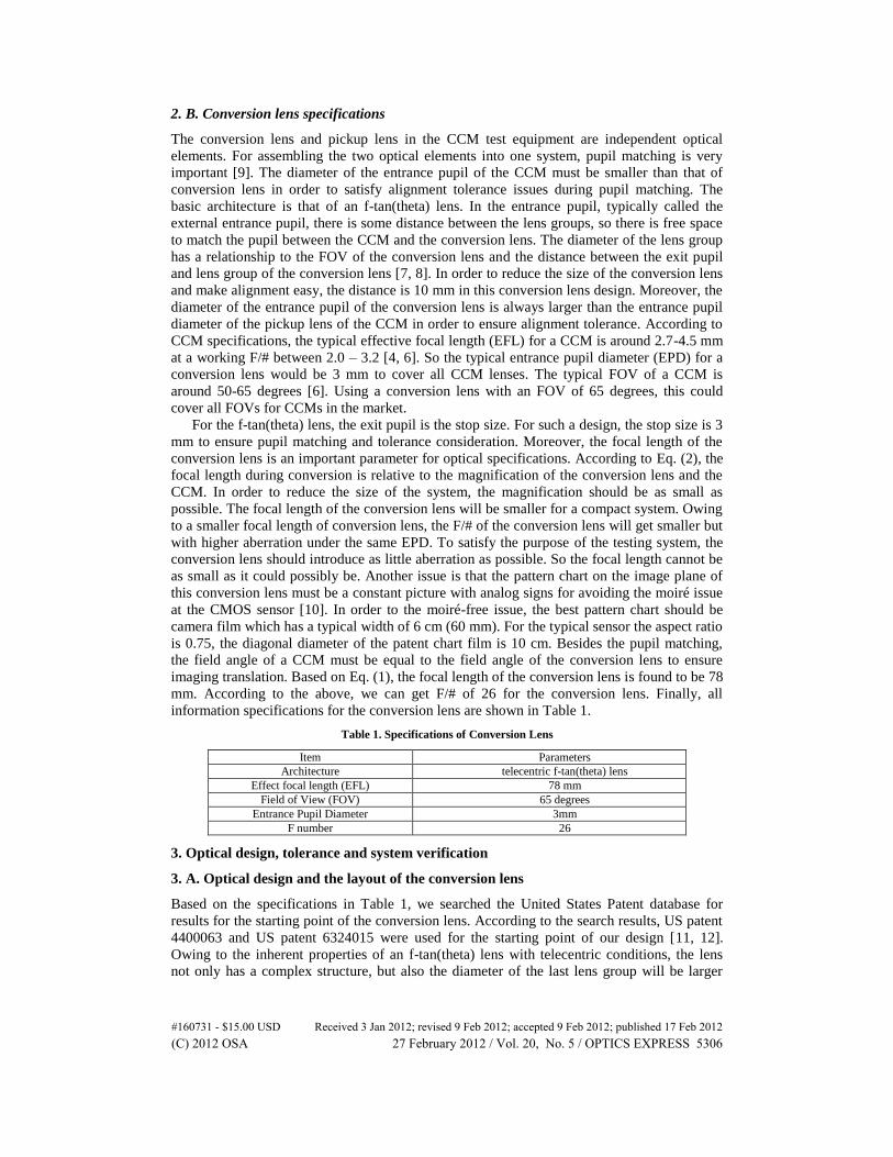
mm. According to the above, we can get F/# of 26 for the conversion lens. Finally, all
information specifications for the conversion lens are shown in Table 1.
Table 1. Specifications of Conversion Lens
Item Parameters
Architecture telecentric f-tan(theta) lens
Effect focal length (EFL) 78 mm
Field of View (FOV) 65 degrees
Entrance Pupil Diameter 3mm
F number 26
3. Optical design, tolerance and system verification
3. A. Optical design and the layout of the conversion lens
Based on the specifications in Table 1, we searched the United States Patent database for
results for the starting point of the conversion lens. According to the search results, US patent
4400063 and US patent 6324015 were used for the starting point of our design [11, 12].
Owing to the inherent properties of an f-tan(theta) lens with telecentric conditions, the lens
not only has a complex structure, but also the diameter of the last lens group will be larger
#160731 - $15.00 USD Received 3 Jan 2012; revised 9 Feb 2012; accepted 9 Feb 2012; published 17 Feb 2012(C) 2012 OSA 27 February 2012 / Vol. 20, No. 5 / OPTICS EXPRESS 5306
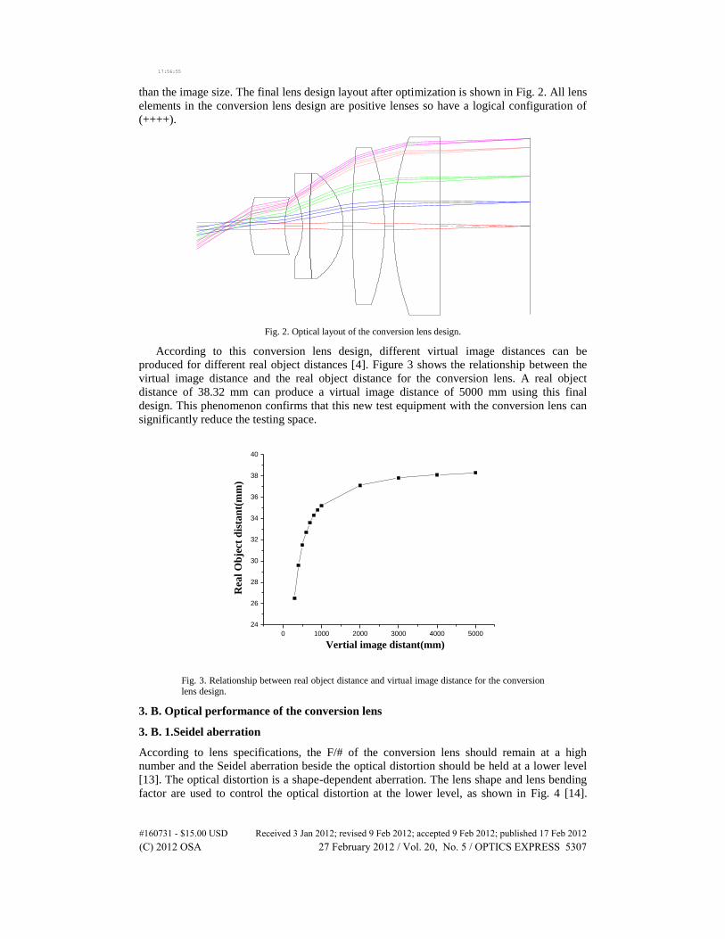
than the image size. The final lens design layout after optimization is shown in Fig. 2. All lens
elements in the conversion lens design are positive lenses so have a logical configuration of
(++++).
17:56:55
Fig. 2. Optical layout of the conversion lens design.
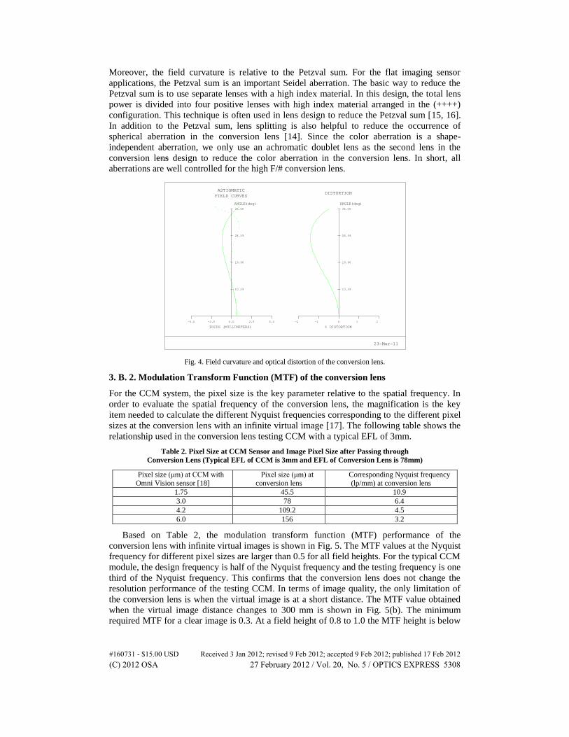
According to this conversion lens design, different virtual image distances can be
produced for different real object distances [4]. Figure 3 shows the relationship between the
virtual image distance and the real object distance for the conversion lens. A real object
distance of 38.32 mm can produce a virtual image distance of 5000 mm using this final
design. This phenomenon confirms that this new test equipment with the conversion lens can
significantly reduce the testing space.
0 1000 2000 3000 4000 5000
24
26
28
30
32
34
36
38
40
Rea
l O
bje
ct d
ista
nt(
mm
)
Vertial image distant(mm)
Fig. 3. Relationship between real object distance and virtual image distance for the conversion lens design.
3. B. Optical performance of the conversion lens
3. B. 1.Seidel aberration
According to lens specifications, the F/# of the conversion lens should remain at a high
number and the Seidel aberration beside the optical distortion should be held at a lower level
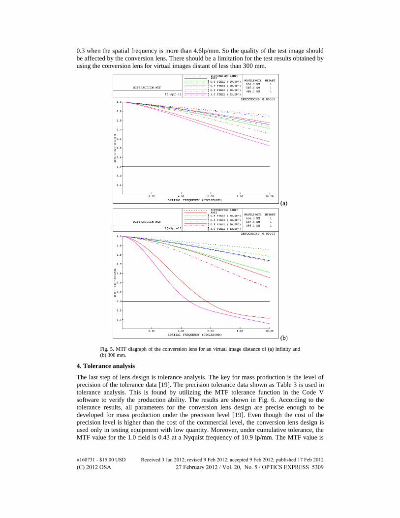
[13]. The optical distortion is a shape-dependent aberration. The lens shape and lens bending
factor are used to control the optical distortion at the lower level, as shown in Fig. 4 [14].
#160731 - $15.00 USD Received 3 Jan 2012; revised 9 Feb 2012; accepted 9 Feb 2012; published 17 Feb 2012(C) 2012 OSA 27 February 2012 / Vol. 20, No. 5 / OPTICS EXPRESS 5307
Moreover, the field curvature is relative to the Petzval sum. For the flat imaging sensor
applications, the Petzval sum is an important Seidel aberration. The basic way to reduce the
Petzval sum is to use separate lenses with a high index material. In this design, the total lens
power is divided into four positive lenses with high index material arranged in the (++++)
configuration. This technique is often used in lens design to reduce the Petzval sum [15, 16].
In addition to the Petzval sum, lens splitting is also helpful to reduce the occurrence of
spherical aberration in the conversion lens [14]. Since the color aberration is a shape-
independent aberration, we only use an achromatic doublet lens as the second lens in the
conversion lens design to reduce the color aberration in the conversion lens. In short, all
aberrations are well controlled for the high F/# conversion lens.
14:36:43
ASTIGMATIC
FIELD CURVES
ANGLE(deg)ST
36.00
28.59
19.96
10.29
-5.0 -2.5 0.0 2.5 5.0
FOCUS (MILLIMETERS)
DISTORTION
ANGLE(deg)
36.00
28.59
19.96
10.29
-2 -1 0 1 2
% DISTORTION
23-Mar-11
Fig. 4. Field curvature and optical distortion of the conversion lens.
3. B. 2. Modulation Transform Function (MTF) of the conversion lens
For the CCM system, the pixel size is the key parameter relative to the spatial frequency. In
order to evaluate the spatial frequency of the conversion lens, the magnification is the key
item needed to calculate the different Nyquist frequencies corresponding to the different pixel
sizes at the conversion lens with an infinite virtual image [17]. The following table shows the
relationship used in the conversion lens testing CCM with a typical EFL of 3mm.
Table 2. Pixel Size at CCM Sensor and Image Pixel Size after Passing through
Conversion Lens (Typical EFL of CCM is 3mm and EFL of Conversion Lens is 78mm)
Pixel size (μm) at CCM with
Omni Vision sensor [18]
Pixel size (μm) at
conversion lens
Corresponding Nyquist frequency
(lp/mm) at conversion lens
1.75 45.5 10.9
3.0 78 6.4
4.2 109.2 4.5
6.0 156 3.2
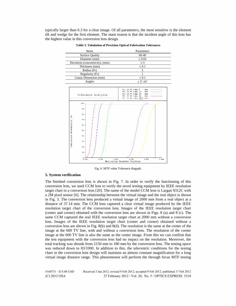
Based on Table 2, the modulation transform function (MTF) performance of the
conversion lens with infinite virtual images is shown in Fig. 5. The MTF values at the Nyquist
frequency for different pixel sizes are larger than 0.5 for all field heights. For the typical CCM
module, the design frequency is half of the Nyquist frequency and the testing frequency is one
third of the Nyquist frequency. This confirms that the conversion lens does not change the
resolution performance of the testing CCM. In terms of image quality, the only limitation of
the conversion lens is when the virtual image is at a short distance. The MTF value obtained
when the virtual image distance changes to 300 mm is shown in Fig. 5(b). The minimum
required MTF for a clear image is 0.3. At a field height of 0.8 to 1.0 the MTF height is below
#160731 - $15.00 USD Received 3 Jan 2012; revised 9 Feb 2012; accepted 9 Feb 2012; published 17 Feb 2012(C) 2012 OSA 27 February 2012 / Vol. 20, No. 5 / OPTICS EXPRESS 5308
0.3 when the spatial frequency is more than 4.6lp/mm. So the quality of the test image should
be affected by the conversion lens. There should be a limitation for the test results obtained by
using the conversion lens for virtual images distant of less than 300 mm.
Fig. 5. MTF diagraph of the converstion lens for an virtual image distance of (a) infinity and
(b) 300 mm.
4. Tolerance analysis
The last step of lens design is tolerance analysis. The key for mass production is the level of
precision of the tolerance data [19]. The precision tolerance data shown as Table 3 is used in
tolerance analysis. This is found by utilizing the MTF tolerance function in the Code V
software to verify the production ability. The results are shown in Fig. 6. According to the
tolerance results, all parameters for the conversion lens design are precise enough to be
developed for mass production under the precision level [19]. Even though the cost of the
precision level is higher than the cost of the commercial level, the conversion lens design is
used only in testing equipment with low quantity. Moreover, under cumulative tolerance, the
MTF value for the 1.0 field is 0.43 at a Nyquist frequency of 10.9 lp/mm. The MTF value is
#160731 - $15.00 USD Received 3 Jan 2012; revised 9 Feb 2012; accepted 9 Feb 2012; published 17 Feb 2012(C) 2012 OSA 27 February 2012 / Vol. 20, No. 5 / OPTICS EXPRESS 5309
typically larger than 0.3 for a clear image. Of all parameters, the most sensitive is the element
tilt and wedge for the first element. The main reason is that the incident angle of this lens has
the highest value in this conversion lens design.
Table 3. Tabulation of Precision Optical Fabrication Tolerances
Items Parameters
Surface Quality 60-40 Diameter (mm) ± 0.02
Deviation (concentricity), (min) 1-3 Thickness (mm) ± 0.1
Radius (Fr) 5 Regularity (Fr) 1
Linear Dimension (mm) ± 0.1 Angles ± 5-10’
Fig. 6. MTF value Tolerance diagaph.
5. System verification
The finished conversion lens is shown in Fig. 7. In order to verify the functioning of this
conversion lens, we used CCM lens to verify the novel testing equipment by IEEE resolution
target chart in a conversion lens [20]. The name of the model CCM lens is Largan 9312C with
a 2M pixel sensor [6]. The relationship between the virtual image and the real object is shown
in Fig. 3. The conversion lens produced a virtual image of 2000 mm from a real object at a
distance of 37.14 mm. The CCM lens captured a clear virtual image produced by the IEEE
resolution target chart of the conversion lens. Images of the IEEE resolution target chart
(center and corner) obtained with the conversion lens are shown in Figs. 8 (a) and 8 (c). The
same CCM captured the real IEEE resolution target chart at 2000 mm without a conversion
lens. Images of the IEEE resolution target chart (center and corner) obtained without a
conversion lens are shown in Fig. 8(b) and 8(d). The resolution is the same at the center of the
image at the 600 TV line, with and without a conversion lens. The resolution of the corner
image at the 600 TV line is also the same as the center image. From this we can confirm that
the test equipment with the conversion lens had no impact on the resolution. Moreover, the
total tracking was shrunk from 2150 mm to 180 mm by the conversion lens. The testing space
was reduced down to 83/1000. In addition to this, the telecentric conditions for the testing
chart in the conversion lens design will maintain an almost constant magnification for a long
virtual image distance range. This phenomenon will perform the through focus MTF testing
#160731 - $15.00 USD Received 3 Jan 2012; revised 9 Feb 2012; accepted 9 Feb 2012; published 17 Feb 2012(C) 2012 OSA 27 February 2012 / Vol. 20, No. 5 / OPTICS EXPRESS 5310
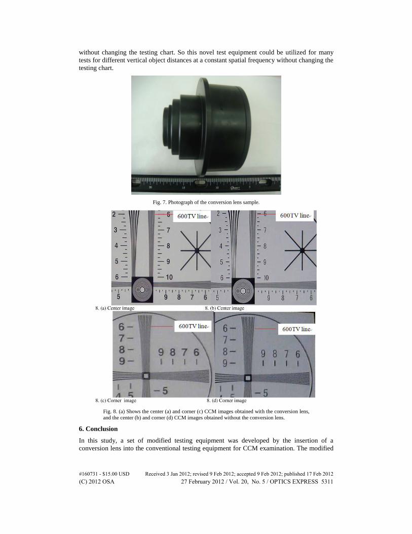
without changing the testing chart. So this novel test equipment could be utilized for many
tests for different vertical object distances at a constant spatial frequency without changing the
testing chart.
Fig. 7. Photograph of the conversion lens sample.
Fig. 8. (a) Shows the center (a) and corner (c) CCM images obtained with the conversion lens,
and the center (b) and corner (d) CCM images obtained without the conversion lens.
6. Conclusion
In this study, a set of modified testing equipment was developed by the insertion of a
conversion lens into the conventional testing equipment for CCM examination. The modified
#160731 - $15.00 USD Received 3 Jan 2012; revised 9 Feb 2012; accepted 9 Feb 2012; published 17 Feb 2012(C) 2012 OSA 27 February 2012 / Vol. 20, No. 5 / OPTICS EXPRESS 5311

testing equipment possessed several advantages over the conventional testing equipment such
as being simple in structure, compact, having a fast test rate, and cost reduction. The modified
testing equipment was quite simple in structure requiring the insertion of only one conversion
lens. The virtual image produced by the conversion lens was compact in volume. This virtual
image was adopted as the new object in the modified testing equipment. The total track of this
modified testing equipment was 83/1000 of the conventional testing equipment at an object
distance of 2000 mm. The image quality obtained using the new testing equipment was also
examined. The conversion lens should not have any effect on image resolution under high
precision tolerance. By using this technology, the cost and space for the novel testing
equipment can be significantly reduced.
Acknowledgments
This study was supported in part by the National Science Council, project number NSC100-
2220-E-009-023 and NSC101-2314-B-384-001, in part by the Chi Mei Medical Center, project
number 100C022 and in part by the "Aim for the Top University Plan" of the National Chiao
Tung University and Ministry of Education, Taiwan.
#160731 - $15.00 USD Received 3 Jan 2012; revised 9 Feb 2012; accepted 9 Feb 2012; published 17 Feb 2012(C) 2012 OSA 27 February 2012 / Vol. 20, No. 5 / OPTICS EXPRESS 5312