comp 208/214/215/216 – lecture 9
DESCRIPTION
COMP 208/214/215/216 – Lecture 9. Design and implementation. Content. Details about: Review Meeting Design Process. Design Review Meeting. This meeting reviews outputs from the design steps It will review 8 items of documentation which should be produced in this phase of the project - PowerPoint PPT PresentationTRANSCRIPT

COMP 208/214/215/216 – Lecture 9
Design and implementation

Content
Details about:
Review Meeting Review Meeting
Design ProcessDesign Process
Design Review Meeting
• This meeting reviews outputs from the design steps
• It will review 8 items of documentation which should be produced in this phase of the project
• This review counts as 20% of your group mark.

Organisation Details• It will take place in week 8 (19 - 23 March) • Teams are responsible for arranging a time for
the review– Send e-mail to reviewer, cc-ed to all group
members– Make your booking by Friday 15 March.
• The documentation to be reviewed must be submitted to the school office on or before 12 noon Friday 15 March.
• Reviews will typically last 20-30 minutes.

Form of the Review
• For each deliverable:– A team member introduces the item– The reviewer may ask questions for
clarification•The team replies to questions
– The reviewer may make comments•The team may briefly respond to
comments• A Report Form will be completed by the
reviewer and given to the team a few days later.

Database Design
• Connolly and Begg give a very detailed step by step guide to design – See Chapters 9-10 & 12-16 (Chapters 6-
17 in 1st edition), summarised in Appendix B.
• Following this method produces a number of documents
• We review the most important items today.

Database Design Method• Logical DB design
– Create and check the ER model– Map ER model to tables
• Physical DB design– Translate Logical DB design for target DBMS– Choose file organization and indexes– Design user views– Design security mechanisms– Design controlled redundancy– Monitor and tune operational system

Documentation to be Reviewed ( for a typical DB project )
• Data Dictionary• Global Logical Data Model (ER Diagram)• Logical Table Structures• Physical Table Structures
• Business Rules• Transaction/Table Matrix• User Interface Design
• Project Gantt Chart.
(1) Data Dictionary• The Data Dictionary is built up throughout the
logical design phase• It should contain all information about the data to
be used by the system• Entities require a description, any aliases used,
and occurrence – See Fig 9.2 (Fig 8.1 in 1st edition)
• For each relationship in which an entity participates we need the multiplicity, the related entities and their multiplicity – See Fig 9.7 (Fig 8.6 in 1st edition)

Extract from data dictionary

Extract from the data dictionary showing descriptions of relationships

(1) Data Dictionary
• For each attribute of an entity, a description, data type and length, whether nulls are allowed and whether it can be multi valued – See Fig 9.8 (Fig 8.7 in 1st edition)
• For each entity its primary and alternate keys – Fig 9.10 (Fig 8.9 in 1st edition)
• Any integrity constraints on attributes resulting from referential integrity and business rule considerations
• Indication of derived data items, and how they are computed – See p. 205 (p. 139 in 1st edition).

Extraction of data dictionary showing descriptions of attributes
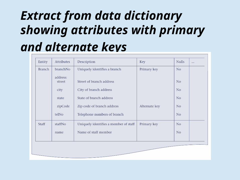
Extract from data dictionary showing attributes with primary and alternate keys

(2) Global Logical Data Model
• During design you may produce local data models for user views
• These are brought together into a global data model. The global data model will be reviewed
• The global data model is a diagram showing:– entities and their primary keys,– relationships between entities and their
direction and multiplicities• An example is given in:
– Figure C.4 p 439 (Figure 10.4 in 1st edition).

Global ER diagram

(3) Logical Table Structure• The Logical Table structures comprise,
for each proposed table:– The name of the table– The columns for that table– the primary key for that table– any alternate keys for that table– any foreign keys for that table, and the
tables they reference
• An example is given – Figure C.3 p. 438 (Figure 10.5 in 1st edition).

Tables for the global logical data model

(4) Physical Table Structure
• The physical table structures comprise, for each table to be implemented,– the name of the table,– the domains of the columns– the column names, their domains, and whether
they may be null– the primary and any alternate keys– any foreign keys and their associated integrity
constraints• An example for one physical table is given at
Figure 12.2 (both editions).
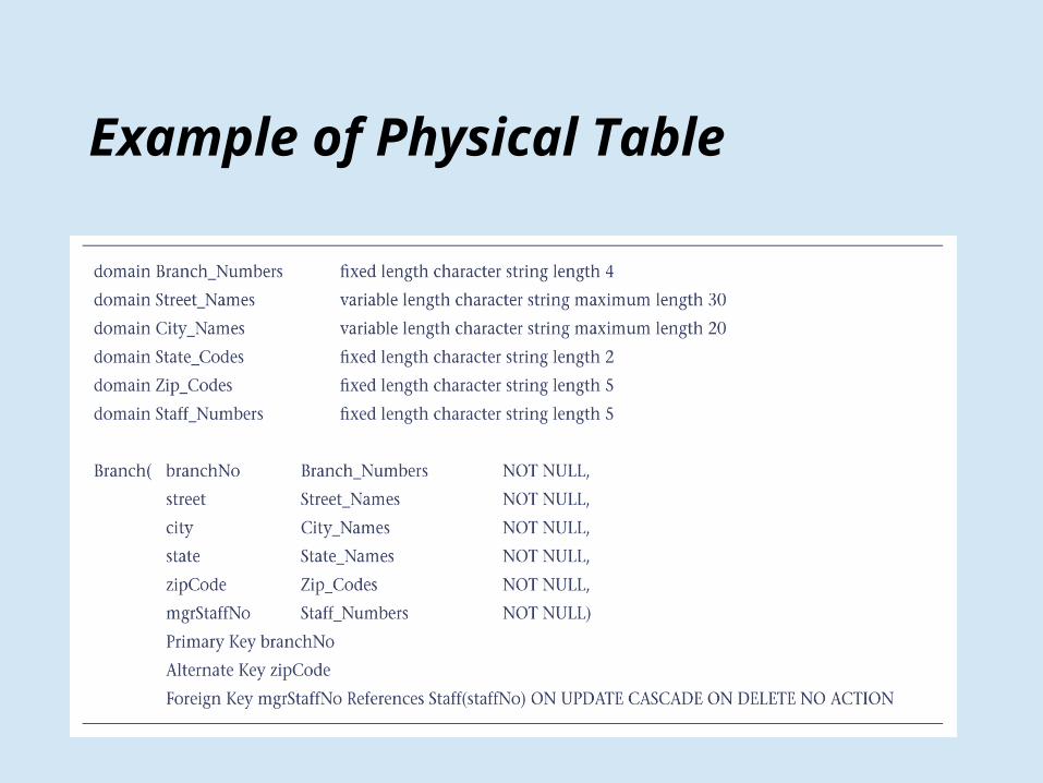
Example of Physical Table

Design considerations• Table structure broken up enough• Example … online shopping (very cut down)• Customer table (0-* card_details, 0-* addresses, 0-* orders)• Customer address table (1 customer)• Customer order table (1 customer, 1-* order_items)• Customer card details table (1 customer)• Customer order_items table (1 order, 1 item)
– e.g. iPhone 3GS, 4 gig sans disk• Items table (1 supplier) (Note 2 suppliers, same item, diff stock code)• Payment transaction table (1 customer)• Return items table (1 customer, 1 order_item)• Supplier table (0-* items)• Staff table (0-* support tickets)• Security log table (1 login user)• Purchase order table (1 supplier, 1-* items)• Support ticket table (1 customer, 1 staff)

Database and performance• Always use index on columns you want to
search on– E.g. MySQL
• ADD address_table INDEX POSTCODE
• Sometimes its faster to do multi table queries separately than as a join
• Always have primary auto index key• Enable slow query log• For very large database tables considering
putting sharding in design

Sharding• Splitting database based on key field• Simple Example
– Customer_table_a (Andrews, Ackroyd)– Customer_table_b (Brown, Beckham)– Customer_table_c (Coope, Carson, Chen)
• Or better, use hash on name• Each table can be stored on separate server• Problems with multi-table queries, like
reports

(5) Business Rules• Business Rules express constraints on data that can
be entered– e.g. 10 books for students, 30 books for staff may be
borrowed from a library
• These are instantiated policies of the client company or organization expressed in the form of rules over the data– Note that Business Rules are more precise than company
policies
• Documentation should show any such rules and how they will be implemented– validation rules on fields– validation rules for records.
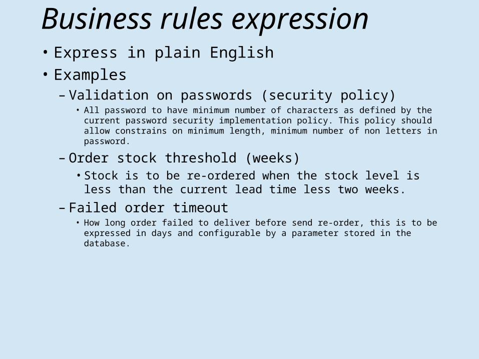
Business rules expression • Express in plain English• Examples
– Validation on passwords (security policy)• All password to have minimum number of characters as defined by the
current password security implementation policy. This policy should allow constrains on minimum length, minimum number of non letters in password.
– Order stock threshold (weeks)• Stock is to be re-ordered when the stock level is less
than the current lead time less two weeks.
– Failed order timeout• How long order failed to deliver before send re-order, this is to be expressed
in days and configurable by a parameter stored in the database.

(6) Transaction/Table Matrix
• The transaction/table matrix shows, for each transaction, what tables are used, and how they are used
• Each table forms a row• Each transaction has four columns
– insert– read– update– delete
• An example is given as Table 13.1 (both editions).

Transactions and tables matrixTransaction (e): Enter details of new member registering at a branch
Transaction (k): Update/delete the details of a given memberTransaction (p): List the title, category and availability of all videos at a specific branch.etc.

Process DesignSome possible additional design tools:
– Use-cases• Descriptions of typical usage situations
– Data flow diagrams• Showing which data items are transferred
between which components, in which scenarios
– Navigation path diagrams – Storyboards – Functional descriptions of components.

Use Cases
• Use Cases show what happens when each type of user interacts with the system– By recording all the ways the system is used
(“cases of use”) we accumulate all the goals or requirements of the system
• The Use Case is a collection of sequences of actions or events relating to a particular goal
• We would typically develop use cases for all the main processes in normal operation, and for many of the processes in abnormal operation.

A Process Map
Home page Register as customer
Customer Login
Browse catalog
Browsecatalog
Put item incart
CustomerLogout
Make purchase
Give paymentdetails

Navigation structure charts
Home page Page 2
Page 3
Page 1 Page 1.1
Page 2.1
Page 2.2

Storyboards• These give an outline of each web-page, showing:
– Where the text is– Where the graphics are, and what these will consist of– Where the links are– etc.
• The term comes from the movie industry– Before a movie is made, each scene is mapped onto
story boards to enable • Planning of rehearsals and shooting • Obtaining props and costumes• Planning of lighting, sound, camera angles, etc.

A storyboard
Page Heading
Advertisement
Links:Link1Link2Link3
Photo ofbook cover
(7) Gantt Chart
• Don’t forget to include a Gantt chart in your documentation and in your presentation– This chart should show your progress so far,
and your plans for the remainder of the project.
– For the next stage (Implementation), your plans should be detailed.
– For later stages, plans may still only be high-level.

Summary
By FRIDAY 23 MARCH 2012• You must book your meeting.• You must supply the design documents
During the week 26/03 - 30/03• You must attend the review meeting• Please attend the meeting punctually• This review is an important milestone: It
documents the design which you will implement in the last phase of the project.