communications system toolbox
TRANSCRIPT
Communications System ToolboxDesign and simulate the physical layer of communication systems
Communications System Toolbox™ provides algorithms and tools for the design, simulation, and analysis ofcommunications systems. These capabilities are provided as MATLAB® functions, MATLAB System objects™,and Simulink® blocks. The system toolbox includes algorithms for source coding, channel coding, interleaving,modulation, equalization, synchronization, and channel modeling. Tools are provided for bit error rate analysis,generating eye and constellation diagrams, and visualizing channel characteristics. The system toolbox alsoprovides adaptive algorithms that let you model dynamic communications systems that use OFDM, OFDMA, andMIMO techniques. Algorithms support fixed-point data arithmetic and C or HDL code generation.
Key Features▪ Algorithms for designing the physical layer of communications systems, including source coding, channel
coding, interleaving, modulation, channel models, MIMO, equalization, and synchronization
▪ GPU-enabled System objects for computationally intensive algorithms such as Turbo, LDPC, and Viterbidecoders
▪ Interactive visualization tools, including eye diagrams, constellations, and channel scattering functions
▪ Graphical tool for comparing the simulated bit error rate of a system with analytical results
▪ Channel models, including AWGN, Multipath Rayleigh Fading, Rician Fading, MIMO Multipath Fading, andLTE MIMO Multipath Fading
▪ Basic RF impairments, including nonlinearity, phase noise, thermal noise, and phase and frequency offsets
▪ Algorithms available as MATLAB functions, MATLAB System objects, and Simulink blocks
▪ Support for fixed-point modeling and C and HDL code generation
System Design, Characterization, and Visualization
The design and simulation of a communications system requires analyzing its response to the noise andinterference inherent in real-world environments, studying its behavior using graphical and quantitative means,and determining whether the resulting performance meets standards of acceptability.
Communications System Toolbox implements a variety of tasks for communications system design andsimulation. Many of the functions, System objects™, and blocks in the system toolbox perform computationsassociated with a particular component of a communications system, such as a demodulator or equalizer. Othercapabilities are designed for visualization or analysis.
System Characterization
The system toolbox offers several standard methods for quantitatively characterizing system performance:
▪ Bit error rate (BER) computations
▪ Adjacent channel power ratio (ACPR) measurements
▪ Error vector magnitude (EVM) measurements
▪ Modulation error ratio (MER) measurements
1

Because BER computations are fundamental to the characterization of any communications system, the systemtoolbox provides the following tools and capabilities for configuring BER test scenarios and accelerating BERsimulations:
BERtool — A graphical user interface that enables you to analyze BER performance of communications systems.You can analyze performance via a simulation-based, semianalytic, or theoretical approach.
Error Rate Test Console — A MATLAB object that runs simulations for communications systems to measureerror rate performance. It supports user-specified test points and generation of parametric performance plots andsurfaces. Accelerated performance can be realized when running on a multicore computing platform.
Multicore and GPU acceleration — A capability provided by Parallel Computing Toolbox™ that enables you toaccelerate simulation performance using multicore and GPU hardware within your computer.
Distributed computing and cloud computing support — Capabilities provided by Parallel Computing Toolboxand MATLAB Distributed Computing Server™ that enable you to leverage the computing power of your serverfarms and the Amazon EC2 Web service.
Performance Visualization
The system toolbox provides the following capabilities for visualizing system performance:
Channel visualization tool — For visualizing the characteristics of a fading channel
Eye diagrams and signal constellation scatter plots — For a qualitative, visual understanding of systembehavior that enables you to make initial design decisions
Signal trajectory plots — For a continuous picture of the signal’s trajectory between decision points
BER plots — For visualizing quantitative BER performance of a design candidate, parameterized by metrics suchas SNR and fixed-point word size
2
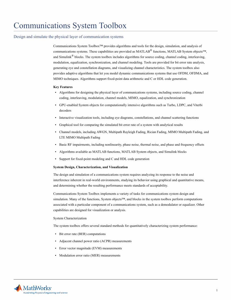
Communication-specific displays for visualizing and analyzing signals at any point or step in your model. Displays include(clockwise from top left): Channel impulse response history, I/Q signal eye diagrams, BER performance plot for theoretical vs.simulated results, and received signal scatter plot.
Analog and Digital Modulation
Analog and digital modulation techniques encode the information stream into a signal that is suitable fortransmission. Communications System Toolbox provides a number of modulation and correspondingdemodulation capabilities. These capabilities are available as MATLAB functions and objects, MATLAB Systemobjects™, and Simulink blocks.
Modulation types provided by the toolbox are:
Analog, including AM, FM, PM, SSB, and DSBSC
Digital, including FSK, PSK, BPSK, DPSK, OQPSK, MSK, PAM, QAM, and TCM
3

MATLAB function (left) and Simulink model (right) with scatter plot for 16 QAM simulation.
Source and Channel Coding
Communications System Toolbox provides source and channel coding capabilities that let you develop andevaluate communications architectures quickly, enabling you to explore what-if scenarios and avoid the need tocreate coding capabilities from scratch.
Source Coding
Source coding, also known as quantization or signal formatting, is a way of processing data in order to reduceredundancy or prepare it for later processing. The system toolbox provides a variety of types of algorithms forimplementing source coding and decoding, including:
▪ Quantizing
▪ Companding (µ-law and A-law)
▪ Differential pulse code modulation (DPCM)
▪ Huffman coding
▪ Arithmetic coding
Channel Coding
To combat the effects noise and channel corruption, the system toolbox provides block and convolutional codingand decoding techniques to implement error detection and correction. For simple error detection with no inherentcorrection, a cyclic redundancy check capability is also available. Channel coding capabilities provided by thesystem toolbox include:
▪ BCH encoder and decoder
▪ Reed-Solomon encoder and decoder
▪ LDPC encoder and decoder
▪ Convolutional encoder and Viterbi decoder
4

▪ Orthogonal space-time block code (OSTBC) (encoder and decoder for MIMO channels)
▪ Turbo encoder and decoder examples
The system toolbox provides utility functions for creating your own channel coding. You can create generatorpolynomials and coefficients and syndrome decoding tables, as well as product parity-check and generatormatrices.
The system toolbox also provides block and convolutional interleaving and deinterleaving functions to reducedata errors caused by burst errors in a communication system:
Block, including General block interleaver, algebraic interleaver, helical scan interleaver, matrix interleaver, andrandom interleaver
Convolutional, including General multiplexed interleaver, convolutional interleaver, and helical interleaver
Channel Modeling and RF Impairments
Channel Modeling
Communications System Toolbox provides algorithms and tools for modeling noise, fading, interference, andother distortions that are typically found in communications channels. The system toolbox supports the followingtypes of channels:
▪ Additive white Gaussian noise (AWGN)
▪ Multiple-input multiple-output (MIMO) fading
▪ Single-input single-output (SISO), Rayleigh, and Rician fading
▪ Binary symmetric
A MATLAB channel object provides a concise, configurable implementation of channel models, enabling you tospecify parameters such as:
▪ Path delays
▪ Average path gains
▪ Maximum Doppler shifts
▪ K-Factor for Rician fading channels
▪ Doppler spectrum parameters
For MIMO systems, the MATLAB MIMO channel object expands these parameters to also include:
▪ Number of transmit antennas (up to 8)
▪ Number of receive antennas (up to 8)
▪ Transmit correlation matrix
▪ Receive correlation matrix
5
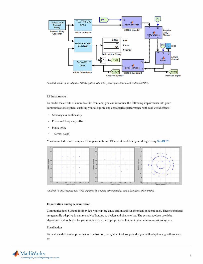
Simulink model of an adaptive MIMO system with orthogonal space-time block codes (OSTBC).
RF Impairments
To model the effects of a nonideal RF front end, you can introduce the following impairments into yourcommunications system, enabling you to explore and characterize performance with real-world effects:
▪ Memoryless nonlinearity
▪ Phase and frequency offset
▪ Phase noise
▪ Thermal noise
You can include more complex RF impairments and RF circuit models in your design using SimRF™.
An ideal 16 QAM scatter plot (left) impaired by a phase offset (middle) and a frequency offset (right).
Equalization and Synchronization
Communications System Toolbox lets you explore equalization and synchronization techniques. These techniquesare generally adaptive in nature and challenging to design and characterize. The system toolbox providesalgorithms and tools that let you rapidly select the appropriate technique in your communications system.
Equalization
To evaluate different approaches to equalization, the system toolbox provides you with adaptive algorithms suchas:
6

▪ LMS
▪ Normalized LMS
▪ Variable step LMS
▪ Signed LMS
▪ MLSE (Viterbi)
▪ RLS
▪ CMA
These adaptive equalizers are available as nonlinear decision feedback equalizer (DFE) implementations and aslinear (symbol or fractionally spaced) equalizer implementations.
Scatter plot of a QPSK signal that shows the signal before and after equalization, as well as the ideal signal constellation.
Synchronization
The system toolbox provides algorithms for both carrier phase synchronization and timing phase synchronization.
For timing phase synchronization, the system toolbox provides a MATLAB Timing Phase Synchronizer objectthat offers the following implementation methods:
▪ Early-late gate timing method
▪ Gardner’s method
▪ Fourth-order nonlinearity method
7

▪ Mueller-Muller method
Simulink model of timing, carrier frequency, and carrier phase recovery for an MSK receiver.
Received signal scatter plot (left), after frequency recovery (middle), and after phase recovery (right).
Stream Processing in MATLAB and Simulink
Most communication systems handle streaming and frame-based data using a combination of temporal processingand simultaneous multifrequency and multichannel processing. This type of streaming multidimensionalprocessing can be seen in advanced communication architectures such as OFDM and MIMO. CommunicationsSystem Toolbox enables the simulation of advanced communications systems by supporting stream processingand frame-based simulation in MATLAB and Simulink.
In MATLAB, stream processing is enabled by System objects™, which use MATLAB objects to representtime-based and data-driven algorithms, sources, and sinks. System objects implicitly manage many details ofstream processing, such as data indexing, buffering, and management of algorithm state. You can mix Systemobjects with standard MATLAB functions and operators. Most System objects have a corresponding Simulinkblock with the same capabilities.
Simulink handles stream processing implicitly by managing the flow of data through the blocks that make up aSimulink model. Simulink is an interactive graphical environment for modeling and simulating dynamic systemsthat uses hierarchical diagrams to represent a system model. It includes a library of general-purpose, predefinedblocks to represent algorithms, sources, sinks, and system hierarchy.
8

Product Details, Examples, and System Requirementswww.mathworks.com/products/communications
Trial Softwarewww.mathworks.com/trialrequest
Saleswww.mathworks.com/contactsales
Technical Supportwww.mathworks.com/support
Implementing a Communications System
Fixed-Point Modeling
Many communications systems use hardware that requires a fixed-point representation of your design.Communications System Toolbox supports fixed-point modeling in all relevant blocks and System objects™ withtools that help you configure fixed-point attributes.
Fixed-point support in the system toolbox includes:
▪ Word sizes from 1 to 128 bits
▪ Arbitrary binary-point placement
▪ Overflow handling methods (wrap or saturation)
▪ Rounding methods: ceiling, convergent, floor, nearest, round, simplest, and zero
Fixed-Point Tool in Simulink Fixed Point™ facilitates the conversion of floating-point data types to fixed point.For configuration of fixed-point properties, the tool tracks overflows and maxima and minima.
Code Generation
Once you have developed your algorithm or communications system, you can automatically generate C code fromit for verification, rapid prototyping, and implementation. Most System objects, functions, and blocks inCommunications System Toolbox can generate ANSI/ISO C code using MATLAB Coder™, Simulink Coder™,or Embedded Coder™. A subset of System objects and Simulink blocks can also generate HDL code.
To leverage existing intellectual property, you can select optimizations for specific processor architectures andintegrate legacy C code with the generated code. You can also generate C code for both floating-point andfixed-point data types.
DSP Prototyping
DSPs are used in communication system implementation for verification, rapid prototyping, or final hardwareimplementation. Using the processor-in-the-loop (PIL) simulation capability found in Embedded Coder, you canverify generated source code and compiled code by running your algorithm’s implementation code on a targetprocessor.
FPGA Prototyping
FPGAs are used in communication systems for implementing high-speed signal processing algorithms. Using theFPGA-in-the-loop (FIL) capability found in HDL Verifier™, you can test RTL code in real hardware for anyexisting HDL code, either manually written or automatically generated HDL code.
Resources
Online User Communitywww.mathworks.com/matlabcentral
Training Serviceswww.mathworks.com/training
Third-Party Products and Serviceswww.mathworks.com/connections
Worldwide Contactswww.mathworks.com/contact
© 2012 The MathWorks, Inc. MATLAB and Simulink are registered trademarks of The MathWorks, Inc. See www.mathworks.com/trademarks for a list ofadditional trademarks. Other product or brand names may be trademarks or registered trademarks of their respective holders. 9