communications system in defence
DESCRIPTION
Description of communication system in India, China and PakistanTRANSCRIPT

AVIONICS REPORT
ON
A STUDY ON COMMUNICATION SYSTEMS OF AIRCRAFT,
SUBMARINES AND SHIPS OF INDIA, PAKISTAN AND CHINA
BATCH NO:1
VENKATA GIRI RAJ.S 13L254
VIJAYA SANKAR. N. R 13L255
ASICK. G 14L432
MOHAMMED FAYIJ 14L438
SAYEETH IMRAN 14L445
BACHELOR OF ENGINEERING
ELECTRONICS AND COMMUNICATION ENGINEERING
October 2015
PSG COLLEGE OF TECHNOLOGY
(Autonomous Institution)
COIMBATORE – 641004

1
PSG COLLEGE OF TECHNOLOGY
(Autonomous Institution)
COIMBATORE – 641004
A STUDY ON COMMUNICATION SYSTEMS OF AIRCRAFT,
SUBMARINES AND SHIPS OF INDIA, PAKISTAN AND CHINA
Bona fide record of work done by
BATCH NO:1
VENKATA GIRI RAJ.S 13L254
VIJAYA SANKAR. N. R 13L255
ASICK. G 14L432
MOHAMMED FAYIJ 14L438
SAYEETH IMRAN 14L445
Dissertation submitted in partial fulfillment of the requirements for the degree of
BACHELOR OF ENGINEERING
ELECTRONICS AND COMMUNICATION ENGINEERING
Of Anna University
October 2015
…..............………………. …...…………………….…
M.Ramasubramniam Dr. S. Subha Rani
Faculty guide Head of the Department

2
ACKNOWLEDGEMENT
I would like to extend my sincere thanks to Dr. R. RUDHRAMOORTHY, Principal, PSG
College of Technology, for his kind patronage.
I am indebted to Dr. S. SUBHA RANI, Professor and Head of the Department of Electronics and
Communication Engineering, for her continued support and motivation.
I would like to express my gratitude to Dr.P. VISALAKSHI, Program coordinator, my technical
report guide Mr. K.R. RADHAKRISHNAN, Assistant Professor Department of Electronics and
Communication Engineering, for their constant motivation, direction and guidance throughout the
entire course of our technical report.
I am grateful to the support extended by my class advisor Mrs. PRABHAVATHI, Associative
Professor, Department of Electronics and Communication Engineering.
I thank all the staff members of the Department of Electronics and Communication Engineering
for their support.
Last but not the least I thank the Almighty and my family members who have been a guiding light
in all our endeavors.

3
TABLE OF CONTENTS
INTRODUCTION................................................................................................................... 7
History of Military communications .................................................................................................................... 7
Military communications equipment ................................................................................................................... 8
Forms of signaling .............................................................................................................................................. 10 Military hand and arm signals ............................................................................................................................. 10 Morse code ............................................................................................................................................................. 10 Radio communications .......................................................................................................................................... 11 Wireless telegraphy ............................................................................................................................................... 12
COMMUNICATIONS SYSTEM ........................................................................................ 13
Based on media ................................................................................................................................................... 13 Optical communication systems ........................................................................................................................... 13 Radio communication systems ............................................................................................................................. 14 Power line communication systems ..................................................................................................................... 14
Based on Technology .......................................................................................................................................... 15 Duplex Communication Systems ......................................................................................................................... 15
Based on Applied Area ....................................................................................................................................... 15 Tactical communications system .......................................................................................................................... 15 Emergency communication system ...................................................................................................................... 15 Automatic call distributor .................................................................................................................................... 16 Voice Communication Control System ............................................................................................................... 16
COMMUNICATION SYSTEMS USED IN AIRCRAFTS............................................... 16
ITU radio spectrum allocations .......................................................................................................................... 17
Aircraft Communications Addressing and Reporting System (ACARS) .......................................................... 18
Via satellite ......................................................................................................................................................... 19
VHF Digital Link ................................................................................................................................................ 20
VHF Digital Link Mode 2 (VDL-2) .................................................................................................................... 21
COMMUNICATION SYSTEMS USED IN SUBMARINES ........................................... 21
COMMUNICATION SYSTEMS USED IN SHIPS .......................................................... 25

4
COMMUNICATION SYSTEMS IN CHINESE DEFENSE ............................................ 27
Aircrafts.............................................................................................................................................................. 27 Y-8X Aircraft ......................................................................................................................................................... 27 KJ-2000 Main ring ................................................................................................................................................ 28 Y-8J Cub ................................................................................................................................................................ 29 Y-8T Cub/High New 4........................................................................................................................................... 30
Submarines ......................................................................................................................................................... 31 Quantum communication ..................................................................................................................................... 31
Battleships and Carriers .................................................................................................................................... 33 Type 815G Electronic Intelligence (ELINT) ship ............................................................................................... 33
COMMUNICATION SYSTEMS IN INDIAN NAVY ...................................................... 34
Communications ................................................................................................................................................. 34
Radiotelephone ................................................................................................................................................... 34
Wireless Link Interface Communications ......................................................................................................... 36
Communication Systems-Indian Navy ............................................................................................................... 37
Sonar and Radars ............................................................................................................................................... 39
Indigenous Sonars and Radars with Indian Navy ............................................................................................. 40
Consolidated Antennas and Sensors .................................................................................................................. 42
MARITIME COMMUNICATION SYSTEM ................................................................... 43
Architecture ........................................................................................................................................................ 43
Topology ............................................................................................................................................................. 43
Future proof ....................................................................................................................................................... 44
Gate X ................................................................................................................................................................. 44
Coastal Radio Services (CR) .............................................................................................................................. 44 Maritime Communication System for Coastal Radio Services (CR) ................................................................ 44
Coastal Surveillance Solutions (CSS) ................................................................................................................. 45 Maritime Communication System for Coastal Surveillance Solutions (CSS) .................................................. 45
Port Communication Solutions (PCS)................................................................................................................ 45 The Port - Gateway to the World ......................................................................................................................... 45

5
COMMUNICATION SYSTEMS IN PAKISTAN NAVY ................................................ 46
Pakistan Selects ASELSAN Systems for Navy Fleet Tanker Defense ............................................................... 46
Remote Controlled Stabilized Naval Gun System (STOP) ................................................................................ 47
Communication Switching System (CSS) .......................................................................................................... 47
Communications for All Naval Platforms .......................................................................................................... 47
Navy-Wide Communications System ................................................................................................................. 48
Integrated Communications System (ICS) ........................................................................................................ 49
Maritime IP Networking .................................................................................................................................... 50
Communications System for Submarines .......................................................................................................... 50
Aircraft Carriers ................................................................................................................................................ 51
Secure Radio-communications ........................................................................................................................... 51
The R&S®M3SR Series4100 radios ................................................................................................................... 52
Data Encryption ................................................................................................................................................. 53
COMPARISON AND FUTURE INFERENCES ON INDIAN DEFENSE ..................... 53
Indian Military Strategic Thinking, Military Doctrine ..................................................................................... 55
Indian Army Expansion Plans ........................................................................................................................... 58
Indian Air Force Expansion Plans ..................................................................................................................... 60
Indian Air Bases ................................................................................................................................................. 61
Indian Naval Expansion Plans ........................................................................................................................... 62
Pakistan Army VS The Indian Army ................................................................................................................. 65
Pakistan Navy Comparison with Indian Navy ................................................................................................... 66
Pakistan Air Force Comparison with Indian Air Force .................................................................................... 67
RESULT................................................................................................................................. 69
BIBLIOGRAPHY ................................................................................................................. 70

6
TABLE OF FIGURES
FIGURE 1 SOVIET PLATOON RADIO SYSTEM ..................................................................................................... 9
FIGURE 2 INTERNATIONAL MORSE CODE SYSTEM ...................................................................................... 10
FIGURE 3 RADIO DIAL ............................................................................................................................................ 11
FIGURE 4 GERMAN HELIOGRAPH ....................................................................................................................... 12
FIGURE 5 SIGNAL LAMP USED TO SEND MORSE CODE ................................................................................. 12
FIGURE 6 GENERAL BLOCK DIAGRAM OF COMMUNICATION SYSTEMS ................................................. 13
FIGURE 7 SIGNAL PROCESSING IN COMMUNICATION .................................................................................. 14
FIGURE 8 COMUNICATION CAPABILITIES OF SUBMARINE OPERATIONS ................................................ 22
FIGURE 9 Y-8X AIRCRAFT ..................................................................................................................................... 27
FIGURE 10 KJ-2000 MAIN RING ............................................................................................................................. 28
FIGURE 11 Y-8J CUB ................................................................................................................................................ 29
FIGURE 12 Y-8T CUB/HIGH NEW 4 ....................................................................................................................... 30
FIGURE 13 KILO-CLASS SUBMARINE ................................................................................................................. 32
FIGURE 14 TYPE 815G SPY SHIPS ......................................................................................................................... 33
FIGURE 15 CONTROL SYSTEM PICTURE ............................................................................................................ 46
FIGURE 16 OUTLINE OF NAVY COMMS ............................................................................................................. 47
FIGURE 17 SUBMARINE ......................................................................................................................................... 50
FIGURE 18 AIRCRAFT CARRIER ........................................................................................................................... 51
FIGURE 19 MULTIBAND RADIO ........................................................................................................................... 52
FIGURE 20 THE R&S®M3TR MULTIBAND RADIOS .......................................................................................... 52
FIGURE 21 DATA ENCRYPTION ENCODER ........................................................................................................ 53

7
Introduction
Military communications or military signals involve all aspects of communications, or
conveyance of information, by armed forces. Military communications span from prehistory to the
present. The earliest military communications were delivered by humans on foot. Later,
communications progressed to visual and audible signals, and then advanced into the electronic
age. Examples for Military Communications include text, audio, facsimile, tactical ground based
communications, terrestrial microwave, tropospheric scatter, naval, satellite communications
systems and equipment, surveillance and signal analysis, encryption and security and direction
finding and jamming.
History of Military communications
The first military communications involved the use of runners or the sending and receiving
of simple signals (sometimes encoded to be unrecognizable). The first distinctive uses of military
communications were called "signals". Modern units specializing in these tactics are usually
designated as "signal corps". The Roman system of military communication (cursus publicus or
cursus vehicularis) is an early example of this. Later, the terms "signals" and "signaler" became
words referring to a highly distinct military occupation dealing with general communications
methods (similar to those in civil use) rather than with weapons.
Present day military forces of an informational society conduct intense and complicated
communicating activities on a daily basis, using modern telecommunications and computing
methods. Only a small portion of these activities are directly related to combat actions. Middle
20th century field systems often required an operator
Modern concepts of network centric warfare (NCW) rely on network oriented methods of
communications and control to make existing forces more effective.

8
Military communications equipment
Drums, horns, flags, and riders on horseback were some of the early methods the military
used to send messages over distances. Many modern pieces of military communications equipment
are built to both encrypt and decode transmissions and survive rough treatment in hostile climates.
They use different frequencies to send signals to other radios and to satellites.
Military communications or "comms" are activities, equipment, techniques, and tactics
used by the military in some of the most hostile areas of the earth and in challenging environments
such as battlefields, on land, underwater and also in air. Military comms include command, control
and communications and intelligence and were known as the C3I model before computers were
fully integrated. The U.S. Army expanded the model to C4I when it recognized the vital role played
by automated computer equipment to send and receive large, bulky amounts of data.
The first military communications tool was the communication automobile designed by the
Soviet Union in 1934 to send and receive signals. The signals were encoded to help prevent the
enemy from intercepting and interpreting top secret communications. The advent of distinctive
signals led to the formation of the signal corps, a group specialized in the tactics of military
communications. The signal corps evolved into a distinctive occupation where the signaler became
a highly technical job dealing with all available communications methods including civil ones.
In the modern world, most nations attempt to minimize the risk of war caused by
miscommunication or inadequate communication. As a result, military communication is intense
and complicated, and often motivates the development of advanced technology for remote systems
such as satellites and aircraft, both manned and unmanned, as well as computers. Computers and
their varied applications have revolutionized military comms. Although military communication
can be used to facilitate warfare, it also supports Intelligence gathering and communication
between adversaries, and thus sometimes prevents war.

9
Figure 1 Soviet Platoon Radio System
There are six categories of military comms: the alert measurement systems, cryptography,
military radio systems, nuclear command control, the signal corps, and network centric warfare.
The alert measurement systems are various states of alertness or readiness for the armed
forces used around the world during a state of war, act of terrorism or a military attack against a
state. They are known by different acronyms, such as DEFCON, or defense readiness condition,
used by the U.S. Armed Forces.
Cryptography is the study of methods of converting messages into disguised, unreadable
information, unless one knows of the method of decryption. This military comms method ensures
that the messages reach the correct hands. Cryptography is also used to protect digital cash,
signatures, digital rights management, intellectual property rights and secure electronic commerce.
It is also used in computing, telecommunications and infrastructure. Military comms use many
kinds of radios. A few are ACP131, AN/ARC164, AN/ARC5, HWU transmitter, Hall crafters
SX28, SCR197, SCR203 and SCR270 radar.

10
Forms of signaling
Military hand and arm signals
Hand and Arm signals are one of the most common forms of communication used by group
of soldiers when a radio silence is in effect or if the soldiers need to remain undetected. Through
the use of these signals military leaders, such as team leaders, squad leaders, platoon leaders, etc...,
are able to keep command and control over their particular element. All new recruits are taught to
use the proper hand and arm signals found in the FM. However, it is not uncommon for units to
adopt and/or create their own signals. These signals ultimately become known as SOP or standard
operating procedure.
Visual signals are any means of communication that require sight and can be used to
transmit prearranged messages rapidly over short distances. This includes the devices and means
used for recognition and identification of friendly forces.
Morse code
Morse code is a method of transmitting text information as a series of on/off tones, lights,
or clicks that can be directly understood by a skilled listener or observer without special equipment.
The International Morse Code encodes the ISO basic Latin alphabet, some extra Latin letters, the
Arabic numerals and a small set of punctuation and procedural signals as standardized sequences
of short and long signals called "dots" and "dashes" or "dits" and "dahs", as in amateur radio
practice.
Figure 2 International Morse code System

11
Radio communications
Radio is the radiation (wireless transmission) of electromagnetic energy through space.
The biggest use of radio waves is to carry information, such as sound, by systematically changing
(modulating) some property of the radiated waves, such as their amplitude, frequency, phase, or
pulse width. When radio waves strike an electrical conductor, the oscillating fields induce an
alternating current in the conductor. The information in the waves can be extracted and
transformed back into its original form.
Radio systems need a transmitter to modulate (changes some property of the energy
produced to impress a signal on it, for example using amplitude modulation, angle modulation
(which can be frequency modulation or phase modulation). Radio systems also need an antenna to
convert electric currents into radio waves, and vice versa. An antenna can be used for both
transmitting and receiving. The electrical resonance of tuned circuits in radios allow individual
stations to be selected. The electromagnetic wave is intercepted by a tuned receiving antenna. A
radio receiver receives its input from an antenna and converts it into a form usable for the
consumer, such as sound, pictures, digital data,
Figure 3 Radio Dial

12
Wireless telegraphy
Wireless telegraphy is the transmission of electric telegraphy signals wirelessly. It is now
used as a historical term for early radio telegraphy systems which communicated with radio waves,
although when the term originated in the late 1800s it was also used for a variety of other
experimental techniques for communicating telegraphically without wires, such as photoelectric
and induction telegraphy.
Other similar forms of signaling include Flag semaphore, Flag signals, Naval flag
signaling, Signal lamp, Heliograph etc…
Figure 4 German Heliograph
Figure 5 Signal lamp Used to send Morse Code
13
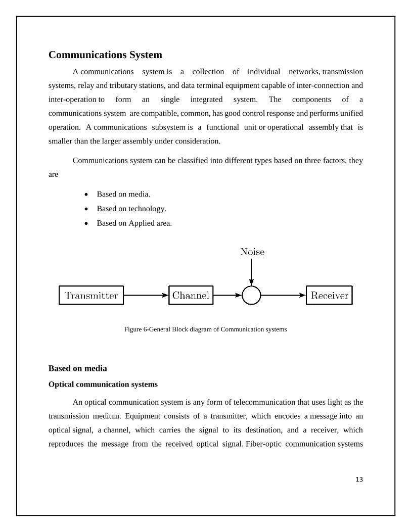
Communications System
A communications system is a collection of individual networks, transmission
systems, relay and tributary stations, and data terminal equipment capable of inter-connection and
inter-operation to form an single integrated system. The components of a
communications system are compatible, common, has good control response and performs unified
operation. A communications subsystem is a functional unit or operational assembly that is
smaller than the larger assembly under consideration.
Communications system can be classified into different types based on three factors, they
are
Based on media.
Based on technology.
Based on Applied area.
Figure 6-General Block diagram of Communication systems
Based on media
Optical communication systems
An optical communication system is any form of telecommunication that uses light as the
transmission medium. Equipment consists of a transmitter, which encodes a message into an
optical signal, a channel, which carries the signal to its destination, and a receiver, which
reproduces the message from the received optical signal. Fiber-optic communication systems

14
transmit information from one place to another by sending light through an optical fiber. The light
forms an electromagnetic carrier wave that is modulated to carry information.
Radio communication systems
A radio communication system is composed of several communications subsystems that
give exterior communications capabilities. A radio communication system comprises a
transmitting conductor in which electrical oscillation or currents are produced and which is
arranged to cause such currents or oscillations to be propagated through the free space medium
from one point to another remote therefrom and a receiving conductor at such distant point adapted
to be excited by the oscillations or currents propagated from the transmitter.
Figure 7 Signal Processing in Communication
Power line communication systems
Power line communication systems operate by impressing a modulated carrier signal on
power wires. Different types of power line communications use different frequency bands,
depending on the signal transmission characteristics of the power wiring used. Since the power
wiring system was originally intended for transmission of AC power, the power wire circuits have
only a limited ability to carry higher frequencies. The propagation problem is a limiting factor for
each type of power line communications.

15
Based on Technology
Duplex Communication Systems
A duplex communication system is a system composed of two connected devices which
can communicate with one another in both directions. Duplex systems are employed in nearly all
communications networks, either to allow for a two-way communication between two connected
devices or to provide a reverse path for the monitoring and remote adjustment of equipment in the
field.
An Antenna is basically a small length of a qwert conductor that is used to radiate or
receive electromagnetic waves. It acts as a conversion device. At the transmitting end it converts
high frequency current into electromagnetic waves. At the receiving end it transforms
electromagnetic waves into electrical signals that is fed into the input of the receiver. Several types
of antenna are used in communication.
Based on Applied Area
Tactical communications system
A tactical communications system is a communications system that
a) is used within, or in direct support of tactical forces,
b) is designed to meet the requirements of changing tactical situations and varying
environmental conditions,
c) provides securable communications, such as voice, data, and video, among mobile
users to facilitate command and control within, and in support of, tactical forces
and
d) usually requires extremely short installation times, usually on the order of hours, in
order to meet the requirements of frequent relocation.
Emergency communication system
An Emergency communication system is any system (computer based) that is organized
for the primary purpose of supporting the two-way communication of emergency messages
16
between both individuals and groups. These systems are commonly designed to integrate the cross-
communication of messages between are variety of communication technologies.
Automatic call distributor
An Automatic call distributor (ACD) is a communication system that automatically queues,
assigns and connects callers to handlers. This is used often in customer service ordering by
telephone or coordination services (such as in air traffic control).
Voice Communication Control System
A Voice Communication Control System (VCCS) is essentially an ACD with
characteristics that make it more adapted to use in critical situations i.e. no waiting for dial tone,
or lengthy recorded announcements, radio and telephone lines equally easily connected to,
individual lines immediately accessible etc...
Communication Systems used in Aircrafts
It used to be that a wing wave or rapid tail deflection was all that was needed by the pilot
of an aircraft to acknowledge a visual queue from a person on the ground. The evolution of
electronic communications equipment is almost as dramatic as the evolution of the aircraft.
Traditional aircraft communications are based on analog voice on either a Very High
Frequency (VHF) or High Frequency (HF) radio waves. In the mid-1980s the use of data-based
communications became a reality. Airspace management is transcending into the computer age
and as new requirements evolve and the choice of communications technologies expand,
regulating the world’s air traffic flow can safely become more automated. Aircraft are currently
being equipped with communications technologies that transport data via satellite plus while they
are on the ground; mobile communication and in some cases broadband networks can receive or
broadcast strategic information regarding aircraft situation and even maintenance trends.
Aircraft communications are being expanded; in fact, in recent years a new abbreviation
has surfaced. CNS ATM stands for “Communication, Navigation, and Surveillance and Air Traffic

17
Management” which was created to support modernization of the dated and overload prone Air
Traffic Control system.
Aircraft that are intended to transport passengers are equipped with radios that enable
analog voice communications. This is currently and will be for the foreseeable future the primary
means for pilots to communicate with different entities of the Air Traffic Control (ATC) system.
ITU radio spectrum allocations
The allocation of radio spectrum is defined by the International Telecommunications Union
(ITU) and relates the use of a frequency to a specific service. In the case of civil aviation there are
separate ITU allocations for communications, navigation, and surveillance. Such differentiation
between functions corresponds to the safety requirements for Air Traffic Control. The ITU has
assigned frequencies for use by aircraft analog voice dialogue in parts of the “High Frequency”
(3-30 MHz) band and in the 118-137 MHz section of the wider “Very High Frequency” range.
Aircraft can use radios operating in the HF radio band for long-range communications as the
signals are reflected by the ionosphere. Unfortunately, when using HF the link audio quality is
very poor due to this long propagation of the wave. Aircraft can use radios operating in the VHF
band to communicate with other radios in line-of-sight coverage. These signals do not reflect off
the ionosphere or penetrate obstacles such as mountains or buildings. The advantage of VHF over
HF is that the link quality is much better and there is greater reuse of the frequency channel. The
use of the word “analog” in relation to voice radio communications means that the changes in the
sound of the voice are converted by the transmitter into corresponding variations in the radio signal
and converted back by the receiver.
This analog system is simpler than more recent digitized voice systems that periodically
measure the sound of the voice, convert the sound into a number in a predefined range, and send
the numbers over the radio link. Aircraft VHF analog radios can use channels of varying width
and the minimum width depends on the precision of the technology.
Aircraft have been using VHF radios for the past six decades and advancements in
electronics have enabled the minimum channel width to be reduced from 100 kHz down to 8.33
kHz, which gives an exponential increase to the number of usable frequencies.

18
Aircraft Communications Addressing and Reporting System (ACARS)
Aircraft began to be equipped with computers in the 1970s and this led to the development
in 1978 of a data communications system called the “Aircraft Communications Addressing and
Reporting System” (ACARS).
Aircraft with ACARS can exchange data messages via a network of automated ground
stations incorporating internal computers. Airlines first used the data link system to send
movement reports to the ACARS service processors using the telex formats that operators had
previously used to send those reports. ACARS are widely used today with airborne installations
exceeding 10,000 aircraft.
ACARS units are connected to a VHF radio and in many cases, interfaced with satellite
systems. This type of data communications is sent via conventional VHF radio waves that are
received through a network of ground stations linked via a terrestrial network to a centralized data
link service processor. This is what provides the connection to the ground systems of the users.
Data communications can also be sent via satellite networks but will ultimately link to the
service processor that supports the VHF ACARS service. The function of the service processor is
to route messages automatically between the user aircraft and ground systems, using mostly a fixed
configuration of delivery addresses by message type for downlink messages and by memorizing
the ground station to be used for uplink messages.
The main restriction on the ACARS system is that it uses character codes representing only
printable characters. This limitation applied to all early generation data communications systems.
This did not prevent the ACARS system from becoming the foundation of airline operations
efficiency. However, the development of new radio communications technology and the need to
support air traffic management, calls for newer technologies to be implemented.

19
Via satellite
Aircraft have been able to carry out voice and data communications via the Inmarsat
satellites for more than 25 years. Until then, this satellite constellation was intended to provide
communication services to ships. The number of aircraft currently equipped to use Inmarsat has
exceeded 3,500 and is made up of airliners, business jets, and government aircraft.
Four satellites placed in geo-stationary orbit above the equator are centralized over the
Pacific Ocean, Indian Ocean, Atlantic Ocean-East, and Atlantic Ocean-West. This constellation
provides coverage through a “global beam” between 80 degrees above and below the equator.
The original Inmarsat Aeronautical service provides two modes, circuit mode supporting
voice communications and packet mode supporting “always-on” data communications.
Aircraft operators use the Inmarsat circuit mode to offer voice service to passengers and
flight deck crew. Aircraft operators use the Inmarsat packet mode, which provides a data rate
approaching that of some home high-speed lines.
The move of aircraft communications from voice to data has motivated some operators of
HF radio ground stations to install “HF data link” (HFDL) computers that enable the transport of
ACARS data. Manufacturers of aircraft HF radios have added capabilities to support ACARS.
The new HF radios can switch between voice and data mode using the same components,
but they are required to give voice communications precedence over data link. This has a tendency
to limit the HFDL availability. This isn’t a commonplace application.
High Frequency radio data link has been found to provide better availability than HF voice
on trans-Polar routes beyond the 80-degree North/South limit of Inmarsat satellite coverage. The
HFDL capacity is only limited by the frequencies available in the HF band. The allocation of HF
frequencies to data link has required a very complex co-ordination process and the system will
quickly reach its limits.

20
The addition of data link capability to HF radio is a way for aircraft operators to get
additional use out of the radios they still carry in order to meet ATC rules when most
communications migrate from voice to data.
VHF Digital Link
The term VHF Digital Link was adopted by the International Civil Aviation Organization
(ICAO) Aeronautical Mobile Communications Panel (AMCP), at its first meeting in November
1991, to refer to digital communications carried on the Aeronautical VHF band. The Aeronautical
VHF Band is the section of the Very High Frequency spectrum allocated to Aeronautical Service
by the International Telecommunications Union. It is made up of the following two groupings:
108-118 MHz assigned to the purpose of radio-navigation and 118-137 MHz which is used for
radio-communications.
The plan for VHF band to become a data carrier was proposed in the ICAO Future Air
Navigation Systems (FANS) committee report issued in 1988. The airline community had
recognized the benefits of aircraft data link communications 10 years before the FANS report and
had implemented the VHF version of ACARS.
The ICAO reserved four VHF channels: 136.900, 136.925, 136.950, and 136.975 MHz for
data communications worldwide. This later decision catered for the reservation of frequencies in
order for such data service to be implemented in an environment when the existing aviation VHF
spectrum was considered saturated and congested with existing VHF channels for air traffic analog
voice.
VHF Digital Link (VDL) was put in motion by 1991 through the effort of the Aeronautical
Mobile Communications Panel (AMCP) with a plan to increase the capacity of the VHF band; and
develop a standard for an Aeronautical Telecommunications Network (ATN) data link service
using VHF radio.
The AMCP has developed standards for VDL Modes 1-4 in which the modes provide
different capabilities which currently have political divisions.

21
Mode 1 was created with the intent of using analog radios incorporating a device to install
a coded signal on the existing carrier wave. This mode was never carried forward as analog radios
were already viewed as dinosaurs. Further considerations brought about Mode 2 and 3 which
present the position of the FAA wanting to use all new digital radios with a 25 kHz frequency
spacing and the Euro control concept of going with 8.33 kHz frequency spacing.
On air transport aircraft, the communications, navigation, and surveillance functions will
continue to be processed by separate devices:
1. Communications : VHF data radio or a satellite data unit;
2. Surveillance : Mode S transponder; and GNSS data link;
3. Navigation : Global positioning systems and instrument landing systems multi-
mode receivers.
VHF Digital Link Mode 2 (VDL-2)
VHF Digital Link Mode 2 (VDL-2) was conceived in the early 1990s as a method of
providing high-speed data communications to aircraft. From the outset VDL-2 was intended to
support safety critical Air Traffic Control communications. In addition, airline operational data
would also be supported by VDL-2; a service traditionally supplied using ACARS.
Global deployment of VDL-2 is now rapidly gaining acceptance by the airlines and Air
Traffic Control agencies. In the United States, the FAA has been using VDL-2 in the Miami region
with selected airlines prior to a nationwide rollout of the system. In Europe, Euro control has
strongly endorsed the operational benefits of VDL-2. Euro control is offering financial assistance
to help airlines install VDL-2 equipment, reduced route charges will follow for properly outfitted
aircraft, and finally a mandate will be introduced to bring about full compliance, possibly, by the
end of the decade.
Communication Systems used in Submarines
Submarines communicate via multiple, complementary RF systems, covering nearly all
the military communications frequencies. No one communications system or frequency band

22
can support all submarine communications requirements. Submarine shipboard communications
systems consist of RF antennas and radio room equipment, both RF transmitters/receivers and
baseband suites. Submarines require a suite of antennas to provide the necessary
communications, navigation, and Identification, Friend or Foe (IFF) capabilities. Submarine
antennas, as compared to surface ship antennas, are unique in design, shape, materials, and
performance due to a submarine's space and weight limitations, extreme environmental
conditions, and stealth considerations. UHF SATCOM provides a relatively high data rate but
requires the submarine to expose a detectable mast-mounted antenna, degrading its primary
attribute - stealth. Conversely, extremely low frequency (ELF) and VLF broadcast
communications provide submarines a high degree of stealth and flexibility in speed and depth,
but are low data rate, submarine-unique and shore-to-submarine only.
The US Navy is investing in new and previously demonstrated techniques for
communicating with submarines at speed and depth for coordinated ASW operations. These
techniques most commonly use either trailing wires or towed buoys for submarine
communications, which impose limitations on the submarine's maneuverability and stealth, and
therefore negatively impact the submarine's ability to fully conduct ASW operations. An
airborne laser which could penetrate shallow water would permit submarine communications
without the restrictions of floating wires or buoys.
Figure 8-Comunication capabilities of submarine operations

23
ELF [Extremely Low Frequency 30 Hz - 300 Hz 10,000 Km - 1,000 Km wavelength] -
This is the only band that can penetrate hundreds of meters below the surface of the ocean. The
US Navy transmits ELF messages using a huge antenna in Wisconsin and Michigan created by
several miles of cable on towers in conjunction with the underlying bedrock. This band is used
to send short coded "phonetic letter spelled out" (PLSO) messages to deeply submerged
submarines that are trailing long antenna wires. The communication is only one way; therefore,
it is used primarily for prearranged signals or to direct the submarine to come closer to the
surface for faster communications. Environmental factors do not have a strong influence on
changing the signal and therefore it is quite reliable
VLF [Very low frequency 3 kHz - 30 kHz 100 Km - 10 Km] This band can penetrate
several meters below seawater and can transmit much more information than ELF, therefore it
is useful for submarine communications when the submarine cannot surface, but can come close
to the surface. It can be affected by salinity gradients in the ocean, but these usually do not
present problems for near-surface submarines. There are natural sources of VLF radiation, but
in general, like ELF, it is not strongly influenced by changes in environmental conditions
therefore it is useful for reliable global communications. The transmission antennas need to be
large, therefore it is primarily used for one-way communications from shore-based command
centers to surface ships and submarines. It can also be used to broadcast to several satellites at
once, which can in turn relay messages to the surface. The Navy's VLF systems serve as a back-
up for global communication use during hostilities when nuclear explosions may disrupt higher
frequencies or satellites are destroyed by enemy actions. VLF is also used for aircraft and vessel
navigation beacons and for transmitting standard frequencies and time signals.
HF [High frequency 3 MHz - 30 MHz 100 m - 10 m] - The Navy makes extensive use of
this band for communications. It is also used for long range ("over-the-horizon") radar. Due to
the sky wave transmission mode, HF radiation can travel great distances, sometimes to the other
side of the earth. Due to its versatility and large coverage area, this is a very crowded band and
the military can only use a few frequency regions scattered throughout this band. The most
efficient transmissions require fairly large antennas; therefore, it is most useful when at least one
of the stations is on shore. The antenna size limits its use on aircraft. It cannot be used for satellite
24
communications since it is reflected by the ionosphere. Many of the former uses of HF by the
Navy are now being taken over by satellite communication systems. However, we expect that
the Navy will continue to use HF for quite some time in the future. The primary drawback to HF
use is that it is highly susceptible to changes in the ionosphere and therefore several frequencies
must be available for use.
One of the immediate tasks delineated by the Navy in "From the Sea" is to continue the
full integration of SSNs into expeditionary task forces. To be effective units of a Naval Task
Group within a joint, Tailored Forward Element (TFE), submarines must be fully interoperable
with both Naval and Joint communication systems. Submarines must be capable of tailoring on-
board capabilities to optimize their support for the Joint Task Force (JTF) and Naval Component
Commanders.
Coordination between multiple assets such as aircraft, surface ships, and submarines is
critical to an effective ASW campaign. Integration of submarines into an overall ASW effort,
arguably the most effective platform for wide area search and tracking, has traditionally been
hampered by lack of or minimal communications to the submarine while deep.
Submarine communications were once limited to those necessary to communicate mission
support information and the minimal command and control that a submarine previously required.
The Navy continues to implement the principles of Network Centric Warfare, where the
capability of the total force is made greater than the contributions of individual platforms through
networking of sensors, weapons control systems, and information systems.
As submarines continue to conduct a variety of missions to include intelligence collection,
Indications and Warning (I & W), anti-submarine warfare, anti-surface warfare, strike warfare,
and mine warfare, they will have to be an integral part of networked sensors and platforms.
Submarines' future missions will require a revolution in communications connectivity and
supporting bandwidth. The vision is to allow submarines to communicate without the current
restrictions of depth and speed and with sufficient bandwidth to maximize the effectiveness of

25
data and intelligence collected by the submarine, such that real-time connectivity and reach-back
is achieved.
The development of these advanced communications has already begun with the
incorporation of Narrowband based systems that are IP architecture based. Following this is
development of a higher data rate antenna and wideband based communications and ultimately
a buoyant cable antenna that allows two-way communications at depth and speed.
Ultimately submerged data exchange and communications capabilities will be a key
enabler for employing off-board vehicles, sensors, and distributed networks of UUVs, sensors
and other payloads.
Communication Systems used in Ships
From the early years of the last century, ships started fitting radio for communicating
distress signals among themselves and with the shore. Radio telegraphy using Morse code was
used in the early part of the twentieth century for marine communication.
Marine communication between ships or with the shore was carried with the help of on
board systems through shore stations and even satellites. While ship-to-ship communication was
brought about by VHF radio, Digital Selective Calling (DSC) came up with digitally remote
control commands to transmit or receive distress alert, urgent or safety calls, or routine priority
messages. DSC controllers can now be integrated with the VHF radio as per SOLAS (Safety of
Life at Sea) convention.
Satellite services, as opposed to terrestrial communication systems, need the help of geo-
stationary satellites for transmitting and receiving signals, where the range of shore stations cannot
reach. These marine communication services are provided by INMARSAT (a commercial
company) and COSPAS – SARSAT (a multi-national government funded agency).

26
While INMARSAT gives the scope of two way communications, the Corpas Sarsat has a
system that is limited to reception of signals from emergency position and places with no facilities
of two way marine communications, indicating radio beacons (EPIRB).
For international operational requirements, the Global Maritime Distress Safety System
(GMDSS) has divided the world in four sub areas. These are four geographical divisions named
as A1, A2, A3 and A4.
Different radio communication systems are required by the vessel to be carried on board
ships, depending on the area of operation of that particular vessel.
A1 – It’s about 20- 30 nautical miles from the coast, which is under coverage of at least one VHF
coast radio station in which continuous DSC alerting is available.
Equipment used: A VHF, a DSC and a NAVTEX receiver (a navigational telex for receiving
maritime and meteorological information).
A2 – This area notionally should cover 400 nautical miles off shore but in practice it extends up
to 100 nautical miles off shore but this should exclude A1 areas.
Equipment used: A DSC, and radio telephone (MF radio range) plus the equipment required for
A1 areas.
A3 – This is the area excluding the A1 & A2 areas. But the coverage is within 70 degrees north
and 70-degree south latitude and is within INMARSAT geostationary satellite range, where
continuous alerting is available.
Equipment used: A high frequency radio and/ or INMARSAT, a system of receiving MSI
(Maritime Safety Information) plus the other remaining systems for A1 and A2 areas.
A4 – These are the areas outside sea areas of A1, A2 and A3. These are essentially the Polar
Regions North and South of 70 degree of latitude.
Equipment used: HF radio service plus those required for other areas.

27
All oceans are covered by HF marine communication services for which the IMO requires
to have two coast stations per ocean region. Today almost all ships are fitted with satellite terminal
for Ship Security Alerts System (SSAS) and for long range identification and tracking as per
SOLAS requirements.
On distress, Search and Rescue operations from Maritime Rescue Co-ordination centers
are carried out among other methods, with the help of most of these marine navigation tools.
Naturally, the sea has become a lot safer with these gadgets and other important navigation
tools recommended by the IMO and as enshrined in GMDSS
Communication Systems in Chinese Defense
Aircrafts
Y-8X Aircraft
Y-8X is PLAN's first long-range maritime patrol aircraft (range 5,000km). It is equipped
with an American Litton AN/APS-504(V3) surface search radar in an enlarged under nose radome
plus western navigational systems for long range patrols over the sea. The aircraft also carries
optical and IR cameras.
Some Y-8Xs (Y-8XG 9271 & 9291) have been upgraded with a FLIR turret installed
underneath the forward fuselage as well as small bar-shaped antennas on both sides of the forward
fuselage. A canoe shaped fairing plus a couple blade antennas were seen attached to the bottom of
middle and aft fuselage, suggesting the aircraft's ELINT mission has been further enhanced with
possibly a new SAR capability.
Figure 9 Y-8X Aircraft
28
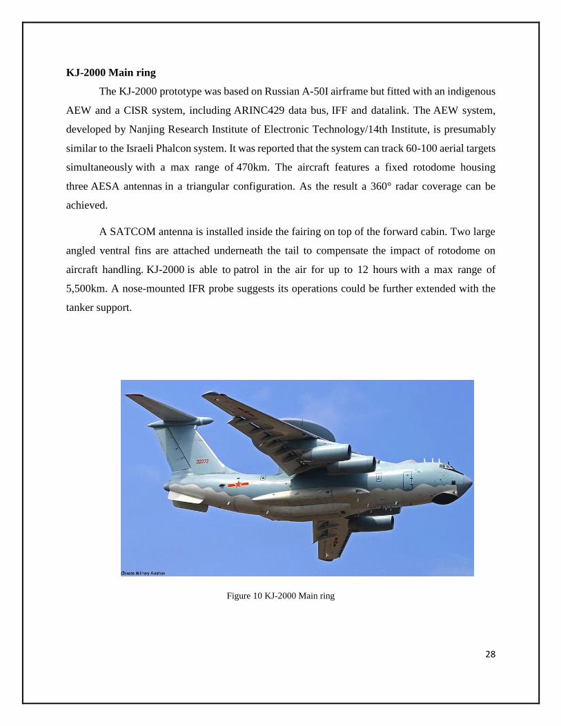
KJ-2000 Main ring
The KJ-2000 prototype was based on Russian A-50I airframe but fitted with an indigenous
AEW and a CISR system, including ARINC429 data bus, IFF and datalink. The AEW system,
developed by Nanjing Research Institute of Electronic Technology/14th Institute, is presumably
similar to the Israeli Phalcon system. It was reported that the system can track 60-100 aerial targets
simultaneously with a max range of 470km. The aircraft features a fixed rotodome housing
three AESA antennas in a triangular configuration. As the result a 360° radar coverage can be
achieved.
A SATCOM antenna is installed inside the fairing on top of the forward cabin. Two large
angled ventral fins are attached underneath the tail to compensate the impact of rotodome on
aircraft handling. KJ-2000 is able to patrol in the air for up to 12 hours with a max range of
5,500km. A nose-mounted IFR probe suggests its operations could be further extended with the
tanker support.
Figure 10 KJ-2000 Main ring
29
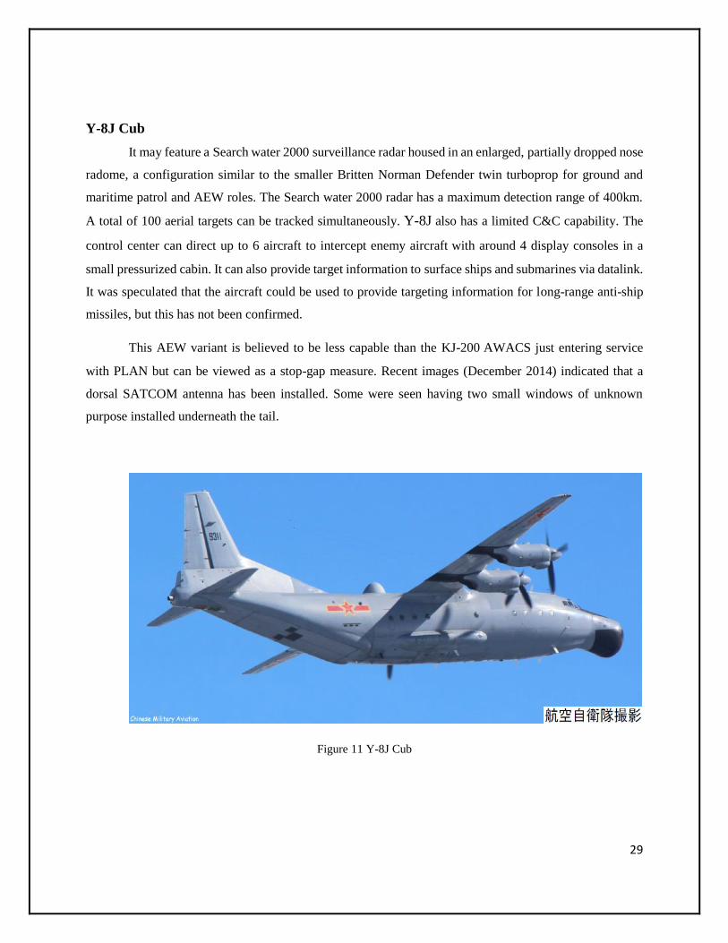
Y-8J Cub
It may feature a Search water 2000 surveillance radar housed in an enlarged, partially dropped nose
radome, a configuration similar to the smaller Britten Norman Defender twin turboprop for ground and
maritime patrol and AEW roles. The Search water 2000 radar has a maximum detection range of 400km.
A total of 100 aerial targets can be tracked simultaneously. Y-8J also has a limited C&C capability. The
control center can direct up to 6 aircraft to intercept enemy aircraft with around 4 display consoles in a
small pressurized cabin. It can also provide target information to surface ships and submarines via datalink.
It was speculated that the aircraft could be used to provide targeting information for long-range anti-ship
missiles, but this has not been confirmed.
This AEW variant is believed to be less capable than the KJ-200 AWACS just entering service
with PLAN but can be viewed as a stop-gap measure. Recent images (December 2014) indicated that a
dorsal SATCOM antenna has been installed. Some were seen having two small windows of unknown
purpose installed underneath the tail.
Figure 11 Y-8J Cub

30
Y-8T Cub/High New 4
It has a redesigned real fuselage section with the loading ramp and tail gun turret removed.
The aircraft also features a dorsal fairing aft the wing section which might house a SATCOM
antenna. Multiple communication antenna arrays can be seen planted along the top and bottom of
the fuselage, as well as on the vertical tailfin.
Figure 12 Y-8T Cub/High New 4
Similarly, there are many developments and innovations in Chinese aircraft design and
many other parameters including the technology behind communication being kept up-to-date till
now.
31
Submarines
Quantum communication
Due to recent technological breakthrough China has been showing off its new hardware, a
potentially more important military advancement has gone largely unnoticed, Chinese scientists
announced a demonstration of "quantum teleportation" over 16 kilometers (10 miles), creating
what Matthew Luce, a researcher at the Defense Group Inc.'s Center for Intelligence Research and
Analysis, calls secure communications guaranteed by the laws of physics. China is now at the
cutting-edge of military communications, transforming the field of cryptography and spotlighting
a growing communications arms race.
While the People's Liberation Army won't be beaming up objects Star Trek-style anytime
soon, the new technology could greatly enhance its command and control capabilities. Scientists
use machines to manipulate units of light called photons. By changing the photons' quantum states
and creating a new, readable pattern not unlike Morse code, they can pass on simple messages or
encryption codes. A group of researchers from Tsinghua University and the Hefei National
Laboratory for Physical Sciences entangled pairs of photons — linking them so changes to one
photon will be instantaneously transferred to the other. Using a high-powered blue laser (the type
China appears to be investing in for its submarine fleet), they then transported the quantum
information farther than anyone had done before, their paper in Nature Photonics claims.
The process is called teleportation, but the information in the message is not actually
moved. Instead, changes to one photon's quantum state will be adopted instantly by the other —
something Einstein famously called spooky action at a distance. The result is akin to having two
pieces of paper 10 miles apart, and as a person writes on one paper the message simultaneously
appears on the other.
Theoretically, this method cannot be cracked or intercepted, If the photons in the laser
beam are observed by a third party, the particles themselves will be altered due to a law of physics
called the Heisenberg Uncertainty Principle, which states that measuring a particle alters it. As
such, the sender and receiver would be immediately informed that someone was snooping.

32
At the 16km distance tested, China would be able to send these secure messages from its
network of satellites to units on the ground, the choice of a blue laser — instead of an infrared one
like the U.S. has been testing — was chosen with its growing submarine fleet in mind since blue
lasers penetrate farther underwater. Soon, Chinese satellites could be able to communicate with
submarines without them needing to surface or give away their location by breaking radio silence.
This may sound like science-fiction, but quantum encryption is already used by a few banks and
governments for highly sensitive information on a smaller scale.
Figure 13 Kilo-class submarine

33
Battleships and Carriers
Types of ships present in republic of china are classified as follows
1. Aircraft carriers
2. Amphibious warfare ships
3. Destroyers
4. Frigates
5. Corvettes
6. Missile boats, submarine chasers and gunboats
7. Mine countermeasures
8. Fleet replenishment
For example
Type 815G Electronic Intelligence (ELINT) ship
The Type 815G ELINT spy ship will still provide a critical role in Chinese naval and joint
operations. Of particular note are the two sensor domes on the Type 815G’s superstructure; the
large size of those domes indicates high sensitivity to record distant enemy radar emissions,
electronic jamming frequencies and communications signals. Type 815G spy ships will help
Chinese commanders prepare and understand the battlefield.
Figure 14 Type 815G spy ships

34
Communication systems in Indian Navy
At sea in war, a naval ship targets the enemy vessels by listening to them through
communication channels by intercepting their messages through wireless radios or seeing them
through radars and sensing them through sonars.
Warship at sea functions like a huge sea creature in respect of a majority of its functions.
For example, there is a need for a ship to see, listen, and communicate; it uses Radars, Sonars and
Communication equipment for these tasks. The overall goal of the warship is to identify and
eliminate the threats arising at sea, thus all the equipment on board a warship is required to function
in unison to achieve this aim. Emphasis in this article would be on Communication equipment,
discussion on technological aspects of Radars and Sonars would be limited to essentials only.
Communications
The first official message from a ship to a shore station, 20 miles away, was sent in 1899,
the first use of radiotelephone between ships was reported in 1916. However, until the installation
of super heterodyne receivers on board ships in 1931, radio communication was considered
unreliable. Radio teletypewriter transmissions between ships were carried out successfully in 1944,
and the first FAX (radio-photo) transmission was that of the surrender document that ended World
War II
Navies use visual, sound, and electrical means for communications. Telecommunication
includes in its ambit transmission, emission, signals, images, sounds, and intelligence information
by visual, oral, wire, radio, or other electronic systems.
Radiotelephone
Ships use radiotelephony because of its ease of operation, directness, and convenience. In
the navy, it is used for communication between ship-to-ship, ship-to-shore, shore-to-ship, air-to-
ship, ship-to-air, air-to-ground, and ground-to-air. The most important use of radiotelephone is in
short-range tactical communication.

35
Radio communication has become a specialized field of electronics. Naval ships today have
the ability to utilize ship-to-shore, ship-to-ship, and ship-to-air, communication circuits. Naval
communication systems vary in complexity depending upon their role, compatibility, and
flexibility. Due to scarcity of space on board a ship, the communication equipment is spread across
the ship’s compartments; however, it is ensured that the sets are capable of operating separately as
well as concurrently. Complex interconnections provide the ability of selectively switching
different configurations.
Radiofrequency bands commonly used for naval communication include, very high
frequency and above, high frequencies, medium frequency, low frequency, very low frequency,
and extremely low-frequency.
Very High Frequency and above (30 MHZ – 300 MHZ) are only used for line of sight
communication as ground range is very less. High Frequency, HF (3 MHZ – 30 MHZ), has been
used by the navy since WW I. HF is used for point-to-point, ship to shore, ground to air and fleet
broadcast (one way only). Medium Frequency, MF (300 KHZ – 3 MHZ), bands in the upper and
lower portions of MF are used by the Navy for ground wave transmission, since the commercial
band generally extends from 535 to 1605 kilohertz. Low Frequency, LF (30 KHZ – 300 KHZ),
band has only a very small part of the radio-frequency spectrum. Low-frequency transmitting
installations have large physical size and high construction and maintenance costs. However, Low-
frequency waves are not so seriously affected during periods of ionosphere disturbance when
communications at the high frequencies are disrupted. This makes LF useful in the northern
latitudes. Very Low Frequency, VLF (3 KHZ – 30 KHZ) provides a highly reliable path for
communications over and under all oceans and seas of the world. Currently all naval VLF
transmitters are used for fleet communications or navigation. VLF transmission is normally a one-
way transmission, a broadcast, where no reply is required. A VLF broadcast of standard time and
frequency signals provides precision for the operation of single-sideband transmissions,
synchronous cryptographic devices, and decoding devices. It is used as a backup to shortwave
communications black out by nuclear activity, as well as in communications to satellites.
Extremely Low Frequency, ELF (Up to 300 HZ), communications are used by the US Navy to

36
send short “phonetic letter spelled out” (PLSO) messages (one-way communication) from
operating authorities to submarines operating at normal mission speeds and depths. ELF penetrates
ocean depths to several hundred feet with little signal loss.
Wireless Link Interface Communications
The US Navy has already begun the deployment of wireless link interface technology on
board 97 of its ships for maritime interception operations. The wireless system will allow
communication directly with boarding teams several miles away. Interdiction units will be able to
transmit biometric data, scanned documents, digital photos, and emails, back to the ship using the
data link. US navy has successfully tested microwave-based wireless wide-area network (WWAN)
between ships to enable incorporation of Long-Term Evolution (LTE) standard, generally referred
to as 4G LTE. It is a standard for high-speed communications among mobile devices, and transmits
data at around 100 megabits/sec, fast enough to handle images and videos as well as voice and
text. The WWAN would normally augment the existing satellite-based communications. The LTE
network would let sailors on ships receive real-time video streaming from air nodes mounted on
helicopters, which in turn would permit officers to make accurate decisions. Oceus Networks is
the likely provider of the systems.
DCNS has developed SYSmart, a commercial wireless communications and tracking
system. It enables exchange of video, voice, and data wirelessly from anywhere on board a ship
using handheld devices. Internet linked video and infrared cameras and other shipboard sensors
can be accessed by the sailors. The system is built around existing Ethernet systems and other
proprietary wireless networks. It has been successfully tested on French naval ships and is to be
incorporated in the next generation of French submarines in 2017.
Rohde & Schwarz in Europe was commissioned to design and build a navy-wide
communications network encompassing shore stations, corvettes, patrol boats, landing crafts of
many sizes and with diverse applications, coastal mine hunters, and maritime patrol aircraft
(MPA). Tailored voice and data communications solutions have been defined for shipboard
internal communications and external line-of-sight (LOS) and beyond-line-of-sight (BLOS) radio

37
communications. A navy-wide military message handling system (MMHS) covers both strategic
and tactical communications. Proprietary applications supplement the STANAG protocols to
include chat and e-mail functionality. In addition, HF and VHF/UHF solutions for IP-based
services have been incorporated. Different subsystems for capabilities such as telephone calls,
announcements, alarms, and internal tactical communications on the ship, message handling, and
radio equipment have been integrated into an overall system. From a single workstation, it would
be possible, to take part in the ship’s internal communications as well as in external voice & data
communications and to manage & control applications and devices.
The French Navy has also selected Rohde & Schwarz to provide R&S®M3SR radio
communications systems for their newest nuclear submarines. The Spanish Navy also decided to
equip their latest tactical submarines with Rohde & Schwarz radio communications systems.
It also provides worldwide communications systems for different kinds of aircraft carriers. The
R&S®M3SR Series4400 is used on the newest and biggest ‘aircraft carrier generation’ that the
United Kingdom’s Royal Navy operates.
Vitavox have been providing the world’s largest navies with military communications
equipment since 1933. The audio equipment provided by Vitavox can be used in a variety of
applications, both above and below deck as well as above and below surface.
Communication Systems-Indian Navy
The Indian Navy is using indigenous systems extensively on its warships, some note-
worthy systems already on board warships and scheduled for fitment on ships under production
are manufactured by BEL, they are: -
ATM Based Integrated Shipboard Data Network (AISDN), it is a multi-services shipboard
network designed to converge all voice traffic, real time video and traditional data communications
onto a single broadband infrastructure. It is a flexible, triple redundant, modular and reliable
network supporting multiple services for naval ships. It integrates various equipment and systems
on board namely EW Systems, Radars, Sonars, CAIO (Computer Aided Information

38
Organization), Fire Control Systems, and a number of other equipment for Ship’s Household Data
(SHHD). It integrates all sensors, weapons, and communication services onto one single
broadband network. It provides integrated and simultaneous transmission of voice, video and data.
It has high system capacity and flexibility and uses fiber optic cable as physical medium.
Composite Communication System (CCS) Mk III is a new generation ATM based
communication system that provides ship-to-ship, ship to shore and ship to air communication. It
is designed as a voice and data integrated network providing connectivity between radio equipment
and remote user onboard for accessing and monitoring and control of radio equipment. The system
is highly flexible and can be configured for all classes of ships. CCS Mk III consists of Control &
Monitoring Subsystems (CMS), which controls and monitors the entire network and enables
operation of radios from remote positions with optimum usage of facilities. Its subsystems are: -
MF Subsystem, it has telegraphy communication and monitors maritime distress
frequency.
HF Subsystem, it has long-range communication on voice, telegraphy & teletype (ship-to-
shore and ship-to-ship) and receives broadcast transmissions.
VHF/UHF Subsystem, Medium range communication on voice, telegraphy & teletype
(ship-to-shore and ship-to-air).
RATT Subsystem, it facilitates tele printer & telegraphic communication from a ship via
radio or land / shoreline.
Versatile Communication System (VCS) Mk III is a versatile system designed to provide
internal communication facilities and display of status of various equipment and systems onboard
naval ships. The system is highly flexible and re-configurable and can be configured for all classes
of ships. It provides, integrated data (Status and Control) and Voice communication from a single
position on IVCS, it uses VOIP technology for Voice & Data communication, it interfaces with

39
the ATM based integrated data network (AISDN) onboard the ship; it reduces wiring and
interconnections in the system.
Sonar and Radars
The other important sensors on a warship for underwater and above water threat detection
are the Sonar and the Radar. It is not intended to discuss the general technical details of such
systems. However, few of the Sonars and Radars frequently in news are being briefly described
below.
Thales Underwater Systems has developed and produced Sonar 2087. It has been designed
to be a variable depth, towed active and passive Sonar system that performs in conjunction with
Sonar 2050 bow-mounted active sonar on UK’s Type 23 frigates. Digital technology in signal
processing and COTS hardware has been used extensively. It is claimed that S2087 will be suitable
for both, littoral environments and Deep Ocean.
Raytheon has developed the AN/SQQ-90 tactical sonar suite for the US Navy’s DDG 1000-
class multi-mission destroyer. The AN/SQQ-90 comprises of the AN/SQS-61 hull-mounted high-
frequency sonar, AN/SQS-60 hull-mounted mid-frequency sonar, and the AN/SQR-20 multi-
function towed array sonar and handling system.
Atlas Elektronik will supply Active Towed Array Sonar, ATAS to the Indian Navy, which
will equip the Delhi and Talwar class ships. ATAS would be subsequently manufactured in India
under cooperation with BEL.
EdgeTech, has delivered 12 advanced side scan sonar systems (mine warfare) for the Indian
Navy.
Enterprise Air Surveillance Radar (EASR) is a development program for replacement for
the SPS-48 and SPS-49 air surveillance radars currently on board US Navy’s amphibious ships

40
and aircraft carriers by the 2020. Northrop Grumman has been awarded an 18-month contract for
the study of the EASR requirement. The new radar system will utilize technologies from the
AN/TPS-80 Ground /Air Task-Oriented Radar (G/ATOR) program.
EMPAR (European Multifunction Phased Array Radar) is a G-band, multifunction, active
phased array radar being developed by Selex for the Italian Navy and French Navy. Its rotating
antenna at 60 rpm provides continuous surveillance, tracking, and weapons fire control. The
EMPAR radar system will be integrated on the Horizon frigates ordered by Italy and France and
the Italian Navy’s Conte di Cavour.
Raytheon’s AN/SPY-5 is an X-band multi-tracking, target-illuminating system for surface
combatants that can simultaneously search, detect, and precisely track multiple surface and air
threats. The SPY-5 is an open architecture, phased-array radar system, providing an advanced self-
defense solution for small and large surface ships operating in the littorals and other maritime
environments. A single radar system consists of three 120-degree beam faces providing full 360-
degree azimuth coverage. The mission capabilities include low-altitude horizon search; focused
volume search; surface search; missile and surface gunfire control; simultaneous threat
illumination; and missile midcourse guidance and terminal homing. It is compatible with all digital
combat management systems, and the radar’s range, accuracy and beam agility enable the full
performance of the Evolved Sea Sparrow Missile (ESSM). SPY-5’s size, weight and overall self-
defense capabilities make it equally well suited for large-deck aircraft carriers and amphibious
assault ships as well as corvettes.
Indigenous Sonars and Radars with Indian Navy
Indigenous Sonars and Radars held by the Indian Navy are manufactured by BEL. Two
important Sonars manufactured by BEL are the Advanced Active cum Passive Integrated Sonar
System (HUMSA NG) and the Integrated Submarine Sonar (USHUS).
HUMSA-NG is an advanced Active cum Passive integrated sonar system to be fitted on a
wide variety of Indian Navy platforms such as the Project 17, Project 15A and Project 28 class

41
ships. HUMSA-NG is an advanced version of the existing HUMSA sonar presently fitted on P16,
P15, Ranjit and Talwar Class of ships. The HUMSA (NG) is designed for enhancing the
system performance, reliability, and maintainability. It is capable of detecting, localizing,
classifying and tracking sub-surface targets in both active and passive modes. The system provides
simultaneous long-range detection in active and passive modes. The sonar is capable of
localization and automatic tracking of up to eight targets in both active and passive modes. The
sonar integrates the operation of the UWT and XBT systems. The system is integrated with FCS
systems such as IAC MOD ‘C and CAIO for exchange of relevant information.
Integrated Submarine Sonar (USHUS) is used to detect, localize and classify underwater
submerged and surface targets through passive listening, interception of signals and active
transmissions of acoustics signals. It has both analog and digital external system interface. It is
modular and rugged in design with upgradeable performance features. Its passive sonar has
performed beams in azimuth and in three vertical directions using ASICS. It can auto track six
targets. Its active sonar has CW and LFM modes of transmission with three selective pulse widths,
high source level, low frequency planar transducer array & complex demodulation, replica
correlation for Doppler and range estimation. Its intercept sonar can provide early warning long
range target detection, all round coverage in three bands, FFT, and Spectral processing. The
underwater communication system has multiple mode acoustic communication in dual frequency
to meet NATO and other requirements, voice, telegraph, data, and message modes of operation.
Its obstacle avoidance sonar is a high frequency short range sonar with rectangular transducer array
and its transmission covers three sectors of 30° each.
Some of the indigenous Radars manufactured by BEL, India are: -
L-Band Surveillance Radar, RAWL02 Mk-III, is long-range L band surveillance radar for
detection of air and surface targets. It has a roll and pitch stabilized antenna platform, Synthesizer
controlled transmitter with TWT amplifier, state of art video extractor track management system
based on COTs technology, low noise receiver combined with split pulse and matched dynamic
range compression, ECCM capability and a range of 270 Km.

42
3D Surveillance Radar, REVATHI, is a state-of-the-art, S-band, Track-While-Scan (TWS)
radar designed to effectively play the role of a medium range surveillance radar mounted on a
stabilized platform for detection of air and surface targets. It has ECCM features, integrated IFF
Mk XI, stabilization against roll & pitch, and remote transmission of data of tracks & plots over
LAN for interface with external systems.
Active & Passive Radar for Navigation & Attack (APARNA), is designed to detect surface
targets, furnish target data to fire control computer for missile firing at these targets in the
autonomous mode from the ship. The radar system is provided with two transmitters–receiver
channels i.e. the first or main channel and the second or navigational channel. The two channels
differ in transmitter peak power, pulse width etc.
Consolidated Antennas and Sensors
Communication technology developments to provide ever-increasing requirements of
multiple bands and bandwidths, foresee a need for large rotating antennas. These pose several
problems on board warships like space availability, electromagnetic interference and increase in
ships radar signature. The trend is tilting towards development of single unit consolidating
antennas and sensors. Thales Netherlands is developing its integrated sensor and communications
suite, which will house radio and data-link communication systems, radar and electro-optical
subsystems and IFF in a single unit.
The US Navy has awarded 18 contracts to develop integration and management
technology for radio frequency radar and communications functions. The objective of the
advanced multifunction radio frequency concept is the integration of radar, electronic warfare and
communications into a common set of apparatus with signal and data processing, signal generation
and display hardware.
Thus from the above it can be appreciated that the field of sensors for utilization on a
warship is an ever expanding one, with new features and capabilities adapted from the commercial
world being added practically every hour. To say the least, the features and capabilities of various
warship sensors by end of this decade are going to be phenomenal.

43
Maritime Communication System
Our maritime communication systems are land-based and support ship-to-land, land-to-
land and ship-to-ship communication. The joint radio and telephone infrastructure enables fast,
safety-critical communication between all different parties involved in MDA. This infrastructure
is managed from designated communication centers. Our systems use the latest and best
technology, and are designed for flexibility: this allows service providers and their organizations
to evolve and strengthen their role in the future of maritime communication.
The MCS 3020 is a combined voice and data switch specifically designed for the needs of
maritime coastal communications. The MCS 3020 uses the proven VCS 3020X application
software and the latest peripheral hardware for interfaces and operator positions.
The MCS is available in various editions the so called "MCS Family" especially designed
to fulfil all individual customer needs in their different surroundings. These include Coastal Radio
Service (CR), Coastal Surveillance Solutions (CSS), Rescue Coordination Centers (MRCC),
Vessel Traffic Services (VTS) and Port Communication Solutions (PCS).
Architecture
The architecture of the MCS 3020 combines optimal performance with low-risk
communication, and is based on a legacy of proven systems unrivalled in safety and reliability.
The MCS 3020 integrates voice communication for radio and telephone, maritime applications
and sensor information in one unique system. It features unlimited conferencing capabilities, as
well as access to all communication channels for any operator, regardless of the system load at any
time and location.
Topology
The MCS 3020 architecture supports hierarchical connectivity for communication
resources and centers. All critical components of the system are duplicated to ensure the
availability of communication paths. The decentralized and modular MCS 3020 provides full
scalability without requiring software changes. So the solution is suited to both small and large
systems, whether a simple port or harbor communication solution, a communication system for

44
VTS centers, a special fully GMDSS-compliant communication system for MRCC, a large coastal
radio system or an extensive communication system for coastal surveillance.
Future proof
The MCS 3020 undergoes constant development. This means, for example, we can already
integrate state of the art communication technologies like VoIP and ROIP (Radio over IP). This
guaranties each customer a solution that is customized perfectly to the infrastructure available
within their existing environment.
Gate X
Meet the new member of the MCS 3020 family: "gate X". This slim module forms the core
switch for smaller applications, such as a port communication system. Despite its size, it uses the
same software and hardware as the very biggest systems on the market, and offers the same
functionality. So MCS 3020 with gate X is the first truly scalable system that has no functional
limitations: you can create any system size required simply by stacking gate X modules.
Coastal Radio Services (CR)
Maritime Communication System for Coastal Radio Services (CR)
Shore to ship, ship to ship, ship to shore and ship to telephone
Due to the decentralized and distributed switching system, the Frequentis MCS CR system
is the most effective way to get all the benefits of a wide range of different radio resources…and
you can access all resources from every point within the network. The Frequentis MCS CSS is
based on the standardized MCS 3020 product family and is equipped with special capabilities and
functions for use in a coastal radio environment.
Multicenter and multi-base station design are the most important factors underpinning
optimal MCS CR functionality, as well as performance capabilities that support almost infinite
voice resources. Each part of the system and each application (DSC, NAVTEX, radio remote
control) is designed for network usage, with free and flexible interconnections between ships and
land subscribers.

45
Coastal Surveillance Solutions (CSS)
Maritime Communication System for Coastal Surveillance Solutions (CSS)
CSS – Detection, Analysis, Communication
The Frequentis solution focuses on highly-integrated systems that use native network
capabilities to enable nationwide or international information and communication networks for
coastal surveillance systems.
The Frequentis MCS CSS is based on the standardized MCS 3020 product family and is
equipped with special capabilities and functions suited to the needs of CSS environments.
Multicenter and multi-base station design are the most important factors underpinning optimal
MCS CSS functionality. The system also supports almost infinite voice resources. Each part of the
system and each application (DSC, NAVTEX, radio remote control) is built for network usage.
Port Communication Solutions (PCS)
The Port - Gateway to the World
A modern, international maritime or inland port typically focuses on local and internal
communication needs, but that’s no reason to avoid the latest technologies. Instead, take advantage
of modern communication technologies like VoIP and state-of-the-art network equipment.
Increase your efficiency by using a fully-digital and centralized switching system to enable access
to all communication resources from any operator position.
Integrate all forms of communication with both sensor information and other data.
Radio -> Telephone -> AIS -> CCTV -> Ship database
The Frequentis MCS PCS is based on the standardized MCS 3020 product family and is
equipped with special capabilities and functions designed for use in port environments. Each part
of the system and each application (DSC, NAVTEX, radio remote control) is laid out for network

46
usage, whether in small systems with just a few operator positions or in applications involving
multiple centers and base stations.
Communication systems in Pakistan Navy
Pakistan Selects ASELSAN Systems for Navy Fleet Tanker Defense
ASELSAN will provide 25 mm STOP Remote Controlled Stabilized Naval Gun System and
Communication Switching System for Pakistan Navy Fleet Tanker Project, Pakistan Ministry of Defense
Production and Turkish Savunma Teknolojileri Mühendislik ve Ticaret A.Ş (STM) have signed a Contract
for the construction of a 15.600 tones Fleet Tanker, on 22 January 2013. ASELSAN, as a subcontractor to
STM, will provide Remote Controlled Stabilized Naval Gun System (STOP), Communication Switching
System (CSS), Integrated Logistics Support (on board and depot spares, maintenance and crew training,
test tools, etc.) as well as consultancy and technical support to Karachi Shipyard Engineering Works
(KS&EW) where the fleet tanker is being constructed.
Figure 15 Control System picture

47
Remote Controlled Stabilized Naval Gun System (STOP)
STOP is a remotely operated stabilized naval gun system fitted with a 25mm Cannon.
STOP configuration is already in service with the Pakistan Navy. The System incorporates
advanced features as remote operation, built-in electro-optic sensor system for autonomous, day
and night operation, stabilized turret (for target detection, tracking and fire on-the-move),
automatic target tracking and ballistic computation.
Communication Switching System (CSS)
CSS provides reliable, fast and secured switching and control functions required for the
tactical communication. CSS enables communication between radios, data/voice crypto devices,
data modems, link terminals, user stations and message handling system. CSS also provides
interfaces to alarm & announcement subsystem and telephone system.
CSS has a modular design, where radio, crypto, modem devices and message handling
system within external communication systems can be configured in accordance to the platform
requirements. CSS enables the user to define/modify the user station functions and communication
requirements within internal communication system by programming operator console software.
Communications for All Naval Platforms
Figure 16 Outline of Navy Comms

48
For more than 30 years now, Rohde & Schwarz has been equipping naval platforms around
the world with complete communications systems. This includes integrated communications
systems (ICS) such as the ones used on shore-based stations, aircraft carriers, frigates and
submarines. Rohde & Schwarz also fits fast attack craft, patrol vessels and small rigid-hulled
inflatable boats with tailored communications solutions.
Small boats are typically equipped with only one radio line for voice and data
communications. Depending on the mission, internal communications are reduced to the basics.
Often, the exchange of information is limited to reporting the vessel’s own position and situation.
Large frigates with multiple communications lines, on the other hand, need a digital
communication network (DCN) to serve as the backbone for internal and external
communications. Radio circuits have to be managed dynamically.
Modern naval communications scenarios are based on large networks at sea and on shore.
To accommodate the resulting needs, Rohde & Schwarz provides solutions for shore stations and
for land-based communications networks that are fully integrated with radio communications at
sea.
Navy-Wide Communications System
Rohde & Schwarz was commissioned to design and build a navy-wide communications
network encompassing the following platforms:
Shore stations
Corvettes
Patrol boats
Landing craft of many sizes and with diverse applications
Coastal minehunters
Maritime patrol aircraft (MPA)

49
In an analysis phase, tailored voice and data communications solutions were defined for
shipboard internal communications and external line-of-sight (LOS) and beyond-line-of-sight
(BLOS) radio communications. A navy-wide military message handling system (MMHS) covers
both strategic and tactical communications. Proprietary applications supplement the STANAG
protocols to include chat and e-mail functionality
.
In addition, HF and VHF/UHF solutions for IP-based services have been incorporated.
Different subsystems for capabilities such as telephone calls, announcements, alarms, internal
tactical communications on the ship, message handling and radio equipment were integrated into
an overall system.
From a single workstation, it is possible, for example, to take part in the ship’s internal
communications as well as in external voice and data communications and to manage and control
applications and devices. Furthermore, the system offers capabilities for interoperable
communications with other armed forces.
Not only was advanced technology employed on the new navy platforms, but existing
systems benefited from comprehensive refit and modernization measures. In order to ensure secure
communications for effective military operations, the project scope also included training
programs covering aspects from maintenance administration to system operation.
Integrated Communications System (ICS)
For the Royal Netherlands Navy, Rohde & Schwarz equipped patrol boats with an
integrated communications system that controls all shipboard communications. The system for
external radio communications consists of R&S®M3SR Series4100 software defined radios for
the HF frequency range and R&S®M3SR Series4400 software defined radios for the VHF and

50
UHF frequency range, which support the latest NATO standards. Due to the use of EPM (ECCM)
waveforms, the system is, of course, jam-resistant. Modems provide data capability and crypto
devices ensure tap-proof communications, which is imperative for a modern navy.
Maritime IP Networking
Rohde & Schwarz supplied the French Navy and other navies with R&S®M3SR
Series4400 radios for IP-based maritime communications. These radio systems make it possible
to form a self-organizing ad hoc IP radio network that, besides a transparent IP interface, features
high-speed data transmission rates. This makes it possible to use common applications, such as e-
mail and chat, and enables transmission of large data volumes, including video transmission.
Communications System for Submarines
Figure 17 Submarine
The French Navy selected Rohde & Schwarz to provide R&S®M3SR radio communications
systems for their newest nuclear submarines. The Spanish Navy also decided to equip their latest tactical
submarines with Rohde & Schwarz radio communications systems. The outstandingly high levels of
quality and reliability of the Rohde & Schwarz radio systems were two of the main reasons why the
company was selected. The company’s deep expertise, combined with its adaptive software defined radio
systems, made it possible to supply these navies with a robust and secure radio communications system that
is ready for many years of service.

51
Aircraft Carriers
Figure 18 Aircraft Carrier
Rohde & Schwarz provides worldwide communications systems for different kinds of aircraft
carriers. The R&S®M3SR Series4400 is used on the newest and biggest aircraft carrier generation that the
United Kingdom’s Royal Navy operates. The radios, which are known in that navy for their high reliability
and excellent RF characteristics, offer a wide range of interfaces and waveforms that comply with NATO
and other standards. In combination with outstanding Rohde & Schwarz VHF/UHF filters and antennas,
the system meets difficult RF system requirements. The system fulfills today’s civil and military
requirements for ground-air-ground communications.
Secure Radio-communications
Rohde & Schwarz software defined radios are designed for shipborne and land-based
defense communications and are used in civil and military air traffic control. They feature a
modular design, a high degree of flexibility and the latest technologies. Standards-based and
proprietary waveforms make it possible to encrypt, and thus secure, voice and data
communications in the HF and VHF/UHF frequency ranges. In order to ensure the security of
every single subscriber’s communications, the R&S®RNMS3000 radio network management
system provides a basis for maintaining consistent configuration of all radio equipment within a
given radio network.
The R&S®M3SR Series4100 radios have been designed for use in permanently connected
deployment in beyond-line-of-sight communications. They are installed in racks within a ship’s radio room
or at a shore station. There, they cover long-haul ship-to-ship and ship-to-shore communications scenarios.
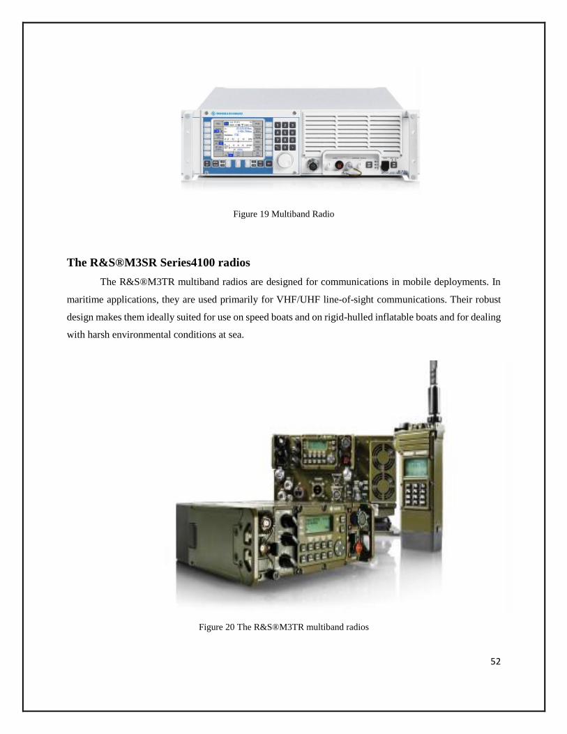
52
Figure 19 Multiband Radio
The R&S®M3SR Series4100 radios
The R&S®M3TR multiband radios are designed for communications in mobile deployments. In
maritime applications, they are used primarily for VHF/UHF line-of-sight communications. Their robust
design makes them ideally suited for use on speed boats and on rigid-hulled inflatable boats and for dealing
with harsh environmental conditions at sea.
Figure 20 The R&S®M3TR multiband radios

53
Data Encryption
Rohde & Schwarz offers encryption devices that have been certified for the most stringent
classification level, cosmic top secret. Consequently, they offer maximum transmission security.
Figure 21 Data Encryption Encoder
Comparison and Future Inferences on Indian Defense
India’s war and military doctrine, which was issued in 2004, apparently stemmed from the
lessons learnt by its extremely slow mobilization during “Operation Parakram”, which was
launched as a result of the attack on the Indian Parliament on 13 December 2001. The strategy that
emerged from this doctrine is known as the “Cold Start Strategy” and has been developed in the
backdrop of a nuclear environment. It specifically targets Pakistan as it visualizes the launching of
eight rapidly-deployable “integrated battle groups,” including those drawn from the Indian Navy
and Air Force and inflicting damage through “improved accuracy, lethality and stand-off capability
of weapons leading to greater destructive capability.” (Indian Military Doctrine 2004) During
“Operation Parakram”, India’s sluggish mobilization had enabled not only Pakistan to effectively
position its own war machines and military arsenal in battle positions but it had also provided

54
ample time and space for the international community to exert heavy diplomatic pressure on India
to back down. India was eager to teach Pakistan a lesson for its alleged support of the perpetrators
of the attack on the Parliament; however, after ten months of a military standoff, it was forced to
withdraw its forces. This major incident forced its military pundits to consider a fresh doctrine,
where Indian forces could be set into action and deliver a telling blow before Pakistan could
retaliate or even consider deploying its nuclear weapons.
A more comprehensive review of India’s military doctrine yields India’s military
expansion plans. India is refashioning its armed forces to attain global reach. The litmus test for
imperialistic designs include, a desire for international military bases, the need to include aircraft
carriers in its fleet, naval expansion, the acquisition of air to air refueling tankers, etc. These are
means of exhibiting long-range force, show of might and hegemonistic aspirations.
The budget of India for the fiscal year of 2011-2012 presented to the Indian parliament on
28thFebruary 2011 allocates rupees 164, 415, 4900,000 to the Indian military; which is
approximately $36.8 billion. This allocation represents an 11.59% growth
From 2010-2015 India is all set to spend approximately $ 80 billion in defence acquisitions.
According to the confederation of India report on “Prospects of Global Defence Export Industry
in Indian Defence Market”, India is spending extravagantly on all three services. The Army is
spending 42.4 Billion, the Air force 24.8 billion and the Navy 12.8 billion US dollars for their
respective acquisitions.
India is planning to enhance its naval fleet by adding Scorpene submarines, aircraft carriers
and carrier borne fighter aircraft and has effectively bolstered its army aviation wing which is
equipped with a massive fleet of combat and noncombat helicopters.
The impact of this will be significant on Pakistan. India intends to ascend on the world
forum as a major world power by 2020. Though Pakistan has nuclear answers to most of India’s
designs to infiltrate Pakistani territory, Pakistan lacks in its capability to fight an aerial battle for
more than 22 days (Pakistan’s Defence Minister Ahmad Mukhtar on Dunya News) and also to

55
project naval might to overcome India’s desires to be in control of the Indian Ocean and its energy
trade routes.
Pakistan has not displayed any desire for military expansion, yet, India’s massive military
expansion, especially its naval expansion and its desire to set up Air Force bases outside its borders,
will definitely have implications for Pakistan’s national security.
Indian Military Strategic Thinking, Military Doctrine
India is fast developing into an economic juggernaut that has yet to achieve its maximum
speed and looking at the way it is poised on the economic and global front, the predictions are that
India will be challenging China as an economic power in the coming century. The Indian economy
is being dubbed as a galloping economy, riding on the wave of information technology and well
educated manpower. In parallel, the Indian armed forces are set to ensure that India will be the
undisputed military power in the region.
During the Cold War, India’s foreign policy and security policy challenges were primarily
Pakistan and China specific. Concurrently, India endeavored to manage the influence of Extra
Regional Forces within the region. But despite maintaining a Non-Aligned status, dependence on
the former Soviet Union particularly for military hardware remained a cornerstone of India’s
foreign policy. The bulk of Indian military procurements, were and continue to be of Soviet origin.
Sustainable economic development has now emerged as one of the key challenges in New
Delhi’s strategic equation. The strategic priorities recently referred to by the Indian PM
accordingly include, economic growth, poverty alleviation, social empowerment, and security
from internal and external threats.
The Indian Military Doctrine was issued in 2004 and is set to be reviewed after every five
years and to be re-written after every ten years. The current document is very detailed and is
structured as a two-part document. The main part contains subjects for widespread dissemination
in the Indian Army; the second part is classified with a restricted circulation.

56
The first part that is not classified has a total of seven chapters with twenty-one sections,
which lay down the guidelines for the Indian military to prepare for war.
The IMD also highlights how the future wars will be fought under Section 2 (Environment
and Threat):
Table 1 – Environment and threat
Emerging at short notice, being of short duration and being fought at high tempo and intensity
Non-linear conduct of operations
Deeper and wider combat zones due to increased reach of integral firepower and surveillance
resources, including space-based systems
Added emphasis on the all-arms concept and need for increased joint man ship between the land,
naval and air forces
Enhanced reliance on a variety of surveillance systems and, resultantly, greater availability of
information contributing to increased transparency of the battlefield
Improved accuracy, lethality and stand-off capability of weapons leading to greater destructive
capability
Ascendancy of Network Centric Warfare (NCW), Information Warfare (IW) and conduct of
operations under the glare of the media
Threat from enemy special forces, insurgents and terrorists to rear areas which will necessitate
earmarking of troops to provide security to lines of communication

57
Various chapters of the IMD all point towards modernization, quick action, maintaining
the element of surprise, preparing for war, conducting operations, operations other than war,
performing joint operations, enhancing logistic support and understanding war.
The strategy that culminates from the IMD is commonly known as the “Cold Start
strategy.” It aims at mobilizing the armed forces swiftly and demands joint cooperation of all three
forces. After a careful study of the IMD, it is quite evident that the IMD 2004 is closely linked
with the Cold Start strategy as it continuously highlights the importance and need for joint
operations, improving logistic support and swift action. The IMD and the annual report of 2010-
2011 issued by the Ministry of Defence clearly points towards Pakistan and Bangladesh as
threats. Since both countries are relatively small as compared to India, therefore, swift action and
mobilization will create an element of surprise and will enable India to dictate its terms.
The Indian Army conducted a massive 10-day field exercise in the Nakodar- Ludhiana-
Nawanshahr-Moga area. In these exercises joint operations were conducted and 8 battle groups
were used; the battle groups comprised of tank regiments, heavy artillery, missile regiments, the
Air Force and the Navy. This strategy is inspired by similar strategies that were used in the US
led allied coalition attack against Iraq in Kuwait in 1991, the air attacks against Kosovo in 1999,
the war against Afghanistan in 2001, and the invasion of Iraq in 2003. This Cold Start strategy
from the IMD has left out one very important point from the equation: Pakistan also maintains
formidable armed services and India’s armed services are not as powerful as that of the US and
their allies combined.
Indian strategists are contemplating on revising the IMD and recently, the Times of India has
reported that the Army Training Command under Lieutenant General AS Lamba has stated that
the focus of the new Indian Military and War Doctrine is upon the following points:
Dealing with the eventuality of a “two-front” war.
Countering “both military and non-military facets of asymmetric and sub-conventional
threats.”

58
Enhancing “strategic reach an out-of-area capability” to protect India’s interests from the
Persian Gulf to the Malacca Strait.
Attaining “operational synergy” between the three services.
Achieving a technological edge over adversaries.
Indian Army Expansion Plans
India is currently the world’s largest importer of weapons; it crossed China in terms of
defence spending between 2006 and 2010(CSIS 2011). It plans to spend approximately $36.28
billion on its military for the year 2011-12(Sanjeev Miglani 2011). From 2010-2015 India is
expected to spend approximately $ 80 billion in defence acquisitions. According to the
confederation of India report on “Prospects of Global Defence Export Industry in the Indian
Defence Market”; India is spending magnanimously on all three services. Each armed service has
a hefty share. The Army is spending $ 42.4 Billion. The Army’s share in the annual budget is 50%
which has been cut down by 5% and this 5% is now shared between the Air force and the Navy.
Army acquisitions will be fragmented. “In its 11th Defense Plan, spanning 2007-2012, the Indian
Army has designated around 600 modernization schemes, amounting to around $1.44 billion,”
India’s MOD report (2010-2011) has an exclusive chapter highlighting the “Arms/Services
Modernization Initiatives.” Elaborate plans for Army modernization have been laid out in this
chapter.
The Armoured Corps is undergoing rapid transformation. Night vision equipment is being
purchased with the latest guns and simulators for training. The contract to equip the T-72 tanks
with night vision has already been concluded, while the gunnery simulators for the T-72 and the
T-90 tanks are still underway and will be concluded soon.
The Mechanized Infantry is also being revolutionized. Contracts for environmental control
systems for the BMP -2/2k and Milan 2T missiles for Recce and Support battalions have been
formalized and concluded. Third generation antitank missiles integrated with heat signature
recognition have also been ordered and will soon be incorporated.

59
As far as the Artillery is concerned the Field Artillery Rationalization Plan (FARP) which
was originally concocted in 1999 is now being implemented with the introduction of two thousand
one hundred and eighty-four guns. It is an $8,000,000,000 plan, with 100 guns being inducted
annually. The focus for procurement of Artillery equipment has primarily been the enhancement
of surveillance capability. Procurement of the Telescopic Mast for Lorros and Heron UAV is at
an advanced stage. Procurement of various other weapons and equipment such as the Pinaka Multi
Barrel Rocket Launcher System, 155SP Gun (Wheeled) and 155mm Ultra-Light Howitzer, 155mm
Towed Gun, Smirch Multi Launcher Rocket System and Vehicle Platform for GRAD BM 21
MBRL is also in progress.
Army Air Defence is also being developed into a modern support group. The Corps
of Army Air Defence is taking massive leaps in the up gradation process of its guns and surface to
air missiles. The Akash Missile System is being procured which is far superior to its predecessor.
Three dimensional tactical control and low level eight Radars are also being incorporated in the
near future thus augmenting the Army Air Defence.
The Army Engineers Corps have been enhanced as well. Many new contracts have been
signed for the procurement of modern technologies with the likes of Reaction Team Boats for high
altitude missions, Trawls for tank T-72 and Engineers to operate in a Nuclear Biological and
Chemical (NBC) environment has also been enhanced with the signing of contracts for Recce
Vehicles, RPL Dosimeter MK II and Reader Personal Dosimeter.
The Signals Corps has undertaken a number of major steps in consolidating the various
networks of the Indian Army. Up gradation of Army Static Switched Communication Network
(ASCON) and Army Wide Area Network (AWAN) is in progress to incorporate the latest
technological changes and further extend the reach of these Procurement of Defence
Communication Network, a prestigious Tri-Service project, is at an advanced stage.
The Infantry within the army is also being revamped and are being given a new look, foot
soldiers are going to be equipped with a wide variety of new weapons and the special forces are
going to be allotted “Bullet Proof Jackets and Ballistic Helmets for counter insurgency operations;
Hand Grenades and Ballistic Shields for Ghatak Platoons etc.”(India 2010) The Futuristic Infantry

60
Soldier as a System (F-INSAS) is a modernization plan developed by the Indian army to
revolutionize its 465 infantry and paramilitary battalions with the state of the art modern weapons
and equipment. This plan will be implemented between 2012 -2020 for which deals are already in
progress. F-INSAS is aimed at giving the Indian army a complete facelift. “The next generation
of ATGW should be in service by 2015” (Padmanabhan 2011) which will enable the army infantry
to become a modern and lethal force. Soldiers will also be equipped with night vision anti-aircraft
guided missiles and by 2020 Indian ground forces will be equipped with all the necessary modern
requirements.
Army Aviation is also being modernized as the Indian armed forces are implementing a
multibillion dollar program through which it will induct approximately 1000 new helicopters. This
includes: attack, transport and utility helicopters. “The choppers to be inducted into the Army,
Navy and Air Force include around 450 light utility, 12 VVIP, over 200 attack, 139 Mi-17 transport
and 15 heavy-lift helicopters and over 50 multi-role helicopters for the Navy.” (Aerospace 19
2011)
Indian Air Force Expansion Plans
Within the next decade, the Indian Air Force will become a formidable force with an
estimated 180 Su-30 aircraft, Medium Multirole Combat Aircraft (MMRCA) which will replace
the obsolete Mig-21 fleet. It is yet to be decided whether this new fleet will comprise of F-16s, F-
18s, Raphael, Eurofighter, SAAB Gripen, or the Mig-35. In addition, there are plans of inducting
approximately 120 Tejas light combat aircraft. New jet trainers, a fleet of 5th generation aircrafts
which remain a secret, Air borne Warning and Control Systems (AWACS), etc. are all a part of
the upgradation process which has been estimated at $ 30.5 billion, if not more. (Samaddar, Mehra
and Behera)
On January 10, 2011, the capability of producing and inducting Tejas, a Mach 1 light
combat aircraft (LCA) was announced by the Aeronautical Development Agency in the presence
of the Raksha Mantri and Chief of Air Staff (CAS) during a formal ceremony held in Bangalore.

61
During this ceremony, the Chief Executive of the Centre for Military Airworthiness and
Certification (CEMILAC) handed over the ‘Release to Service Document (RSD)’ for the LCA
(IOC-I) aircraft to the CAS. Hindustan Aeronautics Limited (HAL) was scheduled to hand over
IOC-II to the IAF in August, 2011. In addition, another contract has been signed to procure 20
additional LCA in Final Operational Clearance (FOC) by December, 2012. (India 2010).
Budget allocation for the air force has increased from 24% of the military budget to 28%
which is illustrated in the above graph taken from the Annual Report of the Indian MOD. The
dollar figure for 2011- 2012 is approximately $10.1 billion.
The Indian Air Force (IAF) has a choice between F-16s, F-18s, Raphael, Euro fighter, and
SAAB Gripens, to replace its aging fleet of MiG-21s. For this purpose, the IAF has issued a tender
for $10.4 billion. This is being regarded as “the mother of all defence deals” (Aerospace 19
2011). Recent reports indicate the tender worth $10.4 billion will be revised to $20 billion in order
to acquire not 126 but 189 aircrafts in the near future. The Times of India stated that “The
“mother” could well become the “granny” of all defence deals in the years ahead.” (Pandit, Biggest
deal: IAF may buy 189 jets for $20bn 2011)
The IAF is not only revamping its aircraft fleet but is also modifying its Radar systems. 15
Low Level Light Weight Radars (LLLWR) are being purchased from Israel. Out of the total of 15,
so far 09 have already been inducted. As a result of these inductions all the Tier-I leaks of the Air
Defence network have been plugged. In addition to these acquisitions, Central Acquisition Radars
(CAR) have been developed domestically by the Laser Research Development Establishment in
cooperation with M/s Bharat Electronics Limited (India 2010).
Indian Air Bases
As mentioned above, the Indian military is acquiring approximately 1000 new helicopters
to be divided amongst all the armed services. Among these 1000 helicopters, being procured with
the intention of strengthening the existing IAF fleet of Russian Mi-35 and Mi-25 combat
helicopters, the IAF is planning to acquire 22 attack helicopters for which Boeing’s Apache 64-D
and the Russian Mi-28 are the contenders. “Trials for the tender have been completed and the

62
report has been submitted with the Air Headquarters and the deal would be signed in the near
future.” (Aerospace 19 2011) The IAF is also on the verge of completing its trial runs for the
procurement of “15 heavy-lift helicopters to replace the fleet of Russian-origin Mi-26. Russian
Mi-26 and the Boeing twin-rotor Chinook 47D are in the race for the tender”. (Aerospace 19 2011)
Indian Naval Expansion Plans
The Indian Navy (IN) is swiftly acquiring state of the art platforms, weapons and sensors
as it foresees a much broader role in the near future. With India’s economic boom, the relevance
of the IN as a diplomatic force multiplier in furthering and defending Indian policies and alliances
is rising[vii]. Given India’s central location the primary area of operations will be the Indian Ocean
Region (IOR). The IN must have the capability to reach out immediately to all areas within this
region to sustain Indian forces, undertake required operations and achieve Indian objectives].
Short to Medium Term. In the short to medium term, the IN would want to keep the
area between Hormuz and Malacca under its strategic influence. Furthermore, the IN would favor
continued support of the U.S.N in the region. Over the next decade, the IN envisages operating
some 160 plus platforms out of which approximately 70 percent will be capable of blue water
deployment across the navy’s primary area of responsibility. The remaining third of the IN’s fleet,
comprising of mine sweepers and off shore patrol vessels (OPVs) would be divided between brown
water offensive/defensive forces and an auxiliary fleet to augment sustainability and reach[ix].
Long Term. In the long term, the IN would want to extend its strategic gaze to cover the
South China Sea, the Pacific, the Red Sea and perhaps beyond in an attempt to become the sole
regional policeman. At this stage, the relevance of the support of external powers would diminish
as India itself would consider itself capable enough of not only managing its own agenda and
objectives but also providing the necessary assistance required in the region. This however would
depend on how rapidly India is able to develop its domestic military industrial infrastructure that
would eventually diminish its dependence on external sources for hardware supplies.
Modernization/Indigenization: Building Indian sea power through a sustained program of
naval expansion is a prerequisite for a global role. The IN has realized that “great fleets need to be

63
built and not bought.” To progress as a truly sea faring nation it must have the internal capability
to match its maritime dreams and ambitions. While substantial assets and technology are being
acquired from other countries, the primary emphasis remains on developing indigenous
capability. As many as 37 ships are under construction in Indian shipyards.
Mazagon Docks Limited and Garden Reach Shipbuilders are notable among
these. Construction of an ambitious Air Defence Ship is also in progress. In addition, the navy
has requested proposals from European, Russian and US shipbuilders for seven project 17A guided
missile frigates; the first of which will be built overseas jointly with Indian designers and the
remaining six at home. Admiral Mehta said the navy is strongly committed to indigenization and
is upgrading shipyard. The IN is also exploring a variety of propulsion technologies for its surface
and subsurface platforms which are progressing satisfactorily.
The Indian Navy has consciously taken the difficult route of indigenization in consonance
with the national endeavor towards self-reliance. The Navy embarked on a program for indigenous
construction of ships and development of major sub systems, sensors and weapon systems with
the help of the Defence Research and Development Organization (DRDO) and the Defence Public
Sector Understandings (PSUs). The present rate of construction is struggling at around 1-5 ships
per year. To meet the target by 2020 the rate of ship building needs to accelerate to 4-5 ships per
year. Self-reliance through indigenization has been the Navy’s guiding philosophy over the last
half century.
The Budget allocation for the Indian navy has been around 14% of the overall military
budget which has now been increased to 15%.
The approval for the induction of the Russian vessel Gorshkov has finally been given. The
Russian Gorshkov has now been christened as the Indian Navy Ship (INS) Vikramaditya. Plans
are now being made for inducting a third carrier. With the arrival of the third carrier it would
become much easier to carry out routine maintenance of the carriers which, in turn, enhances the
life of the carriers. The first carrier was decommissioned only because there was no replacement
for it and it was being over used with insufficient maintenance.

64
Table 2 - Indian Navy’s Major Procurement and Modernization Programs
Project Brief Description
Carrier Programs
The carrier program revolves around extensively
modernizing the INS Viraat, acquiring the ex‐Admiral
Gorshkov from Russia, and perhaps more importantly,
building Vikrant class 40,000 ton aircraft carrier, being
built at Cochin Shipyard expected to enter service in 2012,
while the INS Vishal, a 65,000 ton aircraft carrier is also
being constructed at the Cochin Shipyard.
INS Viraat modification
Major modifications and upgrades of the INS
Viraat hangar include new firewalls, higher speed aircraft
lifts, refits to machinery, etc. Installation of new EW
systems, long‐range surveillance radars, advanced
computer packages for secure and enhanced
communication systems
Admiral Gorchakov
Modification & refit of Admiral Gorshkov includes fitting
a 14‐degree ski jump in place of the existing missile
systems on the bow, etc.
Air Defence Ship (ADS) Construction of two ADS at Cochin Shipyard
Project 15 Delhi Class
Destroyer
Construction of three, large, general‐purpose destroyers,
with a hybrid mix of Russian, Western and Western‐
derived Indian technology in the Mazagaon Dock
Project 17 Frigate
Construction of three units of Frigate in the Mazagaon
Dock
Project 1135.6 Frigate
Three destroyers being ordered from Russia to replace the
dwindling force
of Leander Class frigates
P16A Brahmaputra FFG
Three modified variants of the 3850‐ton Project 16
Godavari Class are in various stages of sea trials, fitting
out and completion at the GRSE yards in Calcutta
Project 25A Kora Class corvettes
Repairing of three 25A Corvettes in the Garden Reach
Shipyard
Modified Tarantul (1241RE)
Class corvettes
An order for two modified Tarantuls ‐ one at the Goa
Shipyard and one at the Mazagaon Dock
SDB Mk 3 FA
Construction of two Fast attack Crafts (FAC) intended for
patrolling coastal waters, policing, anti‐smuggling and
fisheries protection in the Indian EE
Amphibious Ships Construction of the third unit of the Magar class LST
Submarine
Construction of Kilos, modernizing of other eight Kilos,
modernizing the 4 Type 1500 SSK, construction of locally
designed Project 75 SSK, and nuclear SSN or the ATV

65
Pakistan Army VS The Indian Army
The Pakistan Army is considered smaller in number as compared to the Indian army which
is obviously due to the difference in size of the two countries. As of 2011, the Indian army is said
to be “The largest standing volunteer Army in the world” (Indian Army 2011), comprising of more
than a million active troops. In comparison, the Pakistan army’s active manpower is 550,000
highly trained and skilled personnel. Pakistan’s army is proportionally higher in number when it
comes to comparing both the armies in terms of soldier per persons.
The Pakistan army utilizes American and Chinese equipment such as the FIM 92
StingerSAMs, BGM-71 TOW anti-tank missiles, T-82 tanks, etc. In comparison, the Indian army
uses mostly indigenously produced weapons or weapons of soviet origin such as the IR
guided 9K35 Strela-10 SAMs, 3rd Gen IR guided Nag anti-tank missiles, UAVs and a large
inventory of tanks and support vehicles. In terms of quality of equipment, both are evenly
matched. In terms of sheer numbers and inventory, India has an upper hand; however, overall both
forces are quite evenly balanced.
According to the inventory comparison between Pakistan and India presented in table 1.6
the Pakistan Army’s air defence is weak because the countries air defence responsibility lies
primarily with the Pakistan Air Force. Therefore, in comparing air defence systems we need to
compare the Indian Army air defence with the Pakistan Air force air defence. India has 2,395 air
defence guns while Pakistan has 1,900 guns. India has 880 air defence surface to air missiles
whereas the Pakistan Air Force has 150. India needs to maintain a superior air defence due to the
country’s size (Pakistan is one forth the size of India) and higher number of military installations.
The Indian army has a total of 26 aircrafts while the Pakistan army holds 124 aircrafts.
India maintains 4,117 tanks while Pakistan has 2,656 tanks. In order to offset this imbalance; the
Pakistan Army has 14,400 anti-tank weapons whereas India has 3,000.
In terms of Artillery, India maintains 10,758 guns in contrast to Pakistan’s 4,521
guns. This difference in numbers is primarily due to India’s size followed by the fact that India
considers itself surrounded by hostile neighbors. In the annual Indian MOD report 2010-11

66
Bangladesh, Pakistan, Sri Lanka are termed as medium level threats (India 2010) and China is also
considered as a threat. Thus India has to maintain Artillery divisions on all its borders.
Helicopter fleets maintained by the Indian army comprise primarily of utility helicopters
whereas the Pakistan Army maintains helicopters of all categories ranging from attack, support,
training to utility. The total number of helicopters with the Pakistan Army is 182 out of which 25
are attack helicopters. The Indian army has 12 assault helicopters and 210 utility helicopters. The
bulk of the attack helicopters (a fleet of 20) are with the Indian Air Force.
The Indian army has 2 landing crafts whereas the Pakistan army has none. The Indian army
also has 1,786 personnel carriers while the Pakistan Army maintains 1,266.
The Indian Army is much larger in number and also better equipped, however, the
equipment maintained by the Pakistan Army is higher in quality which allows it the ability to
match its rival. The equation will tilt in favour of the Indian army if it successfully carries out its
modernization schemes mentioned in the Indian Army expansion plan.
Pakistan Navy Comparison with Indian Navy
The Pakistan Navy, in comparison with the Indian Navy, is extremely small due to a
smaller coastal area. Despite its size, the Pakistan Navy is not lacking in strategy, tactics,
preparedness and the will to defend which makes it a formidable force.
The Indian Navy has a massive aircraft fleet (92) and, as we saw in the expansion plans of
the Indian military and their “mother of all defence deals” (Aerospace 19 2011), they plan to
purchase naval counterparts of 4th and 5th generation aircrafts as well. This will significantly
enhance their naval air arm. In comparison to India, Pakistan has two squadrons of its Air Force
dedicated to protecting its coasts and another 12 aircrafts are maintained by the navy.
The purchases of the Pakistan Navy are more strategic; therefore, it is maintaining 7 Anti-
submarine aircrafts while India has 4. As far as aerial maritime patrolling is concerned, India has
19 aircrafts while Pakistan has 5. This difference is negligible because of the size of the coastal
region. The coastline of India is 7,000Kms whereas Pakistan’s is only 1,046 km.

67
India currently has one aircraft carrier thus making its navy far superior than Pakistan’s but
at the same time it makes the Indian navy’s task more difficult as maintaining an aircraft carrier
within the fleet requires extra protection to defend this asset.
The Indian navy is far superior in terms of equipment and capability. They have 24
corvettes and 10 destroyers whereas the Pakistan navy has only 1. The number of frigates is evenly
matched as the Pakistan navy relies heavily on its frigates and submarines for the defence of its
shores. India has 10 mine warfare vessels whereas the Pakistan navy has 3.
With the modernization plans set in motion and targeted to be achieved by 2020 the Indian
navy will move one step closer to becoming a blue water navy and the Pakistan Navy will have a
very tough task at its hand.
Pakistan Air Force Comparison with Indian Air Force
Pakistan Air Force has historically fared well against the Indian Air Force in both the
encounters of 1965 as well as 1971, despite being faced with 4 to one odds. This was primarily
due to the far superior weapon systems that the Pakistan Air Force was utilizing at the time. The
F-86 Sabre and the F-104 were far advanced as compared to the “hunters”, “Gnats” and MiG-21s
maintained by the Indian Air Force.
The scenario has now altered. The Indian Air Force has acquired sufficient number of
highly sophisticated aircrafts. The Pakistan Air Force is in a modernizing phase, however,
currently, from its inventory of fighter jets, only the F-16s can counter an Indian Assault.
At present, the fleet of fighter jets maintained by Pakistan Air Force comprise of Mirage
III, Mirage IV, F-16s A, B, C& D, F-7P, F-7 PG and the newly developed JF-17 thunder which
has yet to weaponized. Despite having fighter pilots far superior in training than the Indians, until
Pakistan completes the induction of all the ordered JF-17 thunder aircrafts and also finalizes the
deal of J-10 Aircrafts with China it cannot match the Indian Air Force.
Pakistan Air Force is also modernizing itself. Aircraft tankers are a new edition to the
Pakistan Air Force. Pakistan Air Force has two while the Indian Air Force has six. Similarly, three

68
Air Borne Early Warning Systems have been recently acquired. In the field of reconnaissance, the
Pakistan Air Force is endeavoring to develop a full-fledged squadron of Unmanned Aerial
Vehicles (UAVs).
Table 3- Comparison between India and Pakistan
Pakistan Air Force Equipment India
150 Air Defence
150 Air Defence Surface to Air Missiles
578 Aircraft 1041
3 Aircraft Air Borne Early Warning System
2 Aircraft Electronic Warfare
226 Aircraft Fighter Class 112
192 Aircraft Fighter Ground Attack 419
15 Aircraft Reconnaissance 3
2 Aircraft Tanker 6
112 Aircraft Training 282
26 Aircraft Transport 219
20 Helicopter 326
1 Helicopter Attack 20
4 Helicopter Support 178
15 Helicopter Utility 128
51 Radar
51 Radar land
Air Force and Air Force Reserve Manpower (1000s)
45 Active 127.2
Reserve 140

69
Result Thus the various types of communication systems used in the aircraft, submarines and ships
of India, China and Pakistan is studied, discussed and compared in an elaborate manner. Based on
the results of comparison India has far more man resource than Pakistan and quite equal strength
when compared with China, India needs to Concentrate on developing a new way of
communication which could be difficult for the enemies to decipher as did by China. India’s
Astounding military brilliance and resource should be used in fruit full way by paving way for
developing new technologies rather than improving and re-inventing the older ones.
“A developed and strong India by 2020 or even earlier, is not a dream. It may not even be a
mere inspiration in the minds of many Indians. It is a mission we can all take up and
accomplish”.
- Dr A P J Abdul Kalam

70
Bibliography
- Aerospace 19. March 3,
2011. http://www.india-
defence.com/reports-5051
- Cohen, Stephen P., and
Sunil Dasgupta. “Fighting
Chance.” In Arming
without Aiming, 145.
Washington DC:
Brookings Institution
Press, 2010.
- Cordesman, Anthony H.,
Arliegh A. Burke, Robert
Hammond, and Andrew
Gagel. “CSIS.” Center for
Strategic and
International Studies
CSIS.org. May 16, 2011.
http://csis.org/files/public
ation/110516_South_Asia
-
AsiaMilitaryBalance2011
- CSIS. “Defence Industrial
Initiatives
Group.” CSIS.org. March
29, 2011.
http://csis.org/D3A97763
-

71
81414AC4A2BD8B9AC
A048990/FinalDownload/
DownloadId-
AA86D171D03C8A5A94
ACFBCF0C9A080F/D3
A97763-8141-4AC4-
A2BD-
8B9ACA048990/files/pu
blication/110329_DIIG_
Current_Issues_24_India
n_Defense_Spending.pdf
- Dasgupta, Suni, and
Stephen P. Cohen.
“Arming without
Aiming.” In Arming
without Aiming, 143.
Washington DC:
Brookings Institution
Press, 2010.
- Defence, Ministry of
India. “Indian Military
Doctrine.” 2004.
- Embassy of India
Kabul. August 19, 2011.
http://meakabul.nic.in/
(accessed August 20,
2011).
- Fair, Christine. India in
Afghanistan, part I:
strategic interests,

72
regional
concerns. Washington
DC, October 26, 2010.
- India, Ministry of
Defence. MOD Annual
Report 2010-
2011. Annual Report,
Government of India,
2010.
- Indian Army. Aug 18,
2011.
http://indianarmy.nic.in/S
ite/FormTemplete/frmTe
mpSimple.aspx?MnId=tu
vN2+5ZKVU=&ParentI
D=H1aVkriO4/g=&flag=
p (accessed Aug 19,
2011).
- “International Fund for
Agricultural
Development
(IFAD).” ifad.org. August
2009.
http://www.ifad.org/3EFF
3499-0B2C-4E27-991F-
9E76EF1F838C/FinalDo
wnload/DownloadId-
1F7EEB6536E8DDE787
A1B16217082E44/3EFF
3499-0B2C-4E27-991F-

73
9E76EF1F838C/operatio
ns/projects/regions/Pi/fact
sheets/in.pdf
- Khattak, Masood-Ur-
Rehman.
“eurasiareview.” eurasiar
eview.com. March 29,
2011.
http://www.eurasiareview
.com/indian-strategic-
thinking-a-reflection-of-
kautilyas-six-fold-policy-
analysis-29032011/
- Padmanabhan, Gen.
S. indiandefencereview. J
une 06, 2011.
http://www.indiandefence
review.com/military-and-
aerospace/Indian-Army-
2020.html (accessed July
18, 2011).
- Pandit, Rajat. Army
reworks war doctrine for
Pakistan, China. New
Delhi, December 30,
2009.
- Pandit, Rajat. Biggest
deal: IAF may buy 189
jets for $20bn. New
Delhi, 26 July, 2011.

74
- Perrett, Bradley.
“Aviation Week.” June
21, 2010.
http://www.aviationweek.
com/aw/generic/story_ch
annel.jsp?channel=Aviati
onWeek.com&id=news/a
wx/2010/06/21/awx_06_2
1_2010_p0-
235427.xml&headline=In
dia%20Projected%20To
%20Spend%20$80B%20
On%20Military%20Acqu
isitions%20Through%202
015
- Sanjeev Miglani. With an
eye on China, India steps
up defence
spending. New Delhi,
February 28, 2011.
- The Economist. “The
Other Asian Giant.”
August 06, 2011.
- The World Fact
Book. August 18, 2011.
https://www.cia.gov/libra
ry/publications/the-world-
factbook/fields/2060.html