communications in wireless mimo channels: channel...
TRANSCRIPT

Postgraduate course on
"Communications in wireless MIMOchannels: Channel models,
baseband algorithms, and system design"
Lectures given by
• Prof. Markku Juntti, University of Oulu
• Prof. Tadashi Matsumoto, University of Oulu/ Elektrobit
• Docent Ian Oppermann, University of Oulu/ Southern PoroComm.
• Docent Juha Ylitalo, Nokia/University of Oulu

Course description
1. Introduction (2h) --Juha 17.10
2. Capacity limits of MIMO channels (4h) –Markku 22.10, 24.10
3. MIMO radio channel models (4h) –Juha/Ian 29.10, 31.10
4. Beamforming and diversity (2h) --Juha 5.11
5. Adaptive antenna algorithms (4h) --Juha 7.11, 12.11
6. Example: BLAST (PARC) approach for MIMO (2h) --Juha 14.11
7. Transmit diversity (4h) –Matsumoto 47 19.11, 21.11
8. Example: Transmit diversity techniques for WCDMA (2h) --Juha 26.11
9. Advanced receivers for MIMO: space-time equalisation (4h) –Tad 28.11, 3.12
10.Future prospects for MIMO/ Panel discussion (2h) --All 10.12 at 1pm
Lectures on Tuesdays and Thursdays
Place: Room TL201 (Tutkijantie 2E)
Time: 14:15-16 (except lecture 10)
Dates

Course description, cont'd
• Exam : Date to be determined. Please remember to register for theexam.
• Literature: Mainly journal articles (to appear soon)
• Prerequisites:Necessary: Signals and systems, Digital Filters, Random Signals,Digital Communications I, Digital Communications II,Coding Methods, Radio Communication Channels.
Recommended: Statistical Signal Processing.
Useful background: Information Theory.
• Requirements: Final exam and a few homework problems
• Credit units: To be determined

Course description, cont'd
• As a part of the course an optional homework project willbe arranged. To receive extra credit units a student maydesign and perform a simple study using Matlab.
• The study may consist of Monte-Carlo simulations forShannon capacity or design of a simple CDMA transmitter-channel-receiver chain with multiple antennas and itsperformance evaluation compared to a single antennatransmitter/receiver.
• A report of the study shall be written. Report could be in aform of a 5-page conference paper.

Introduction to the MIMO course
• Short historical note
• Advantages of multi-antenna techniques
• "Smart" antennas (=adaptive antennas)- Beamforming: spatial focusing of correlated signals
- Rx/Tx diversity: combining of decorrelated signals
- MIMO: increasing spectral efficiency/ data rates
• Simple example: SINR improvement
• Definition of MIMO
• Spatial correlation matrix
• Example: Diversity & MIMO in WCDMA
Single signal through
correlated channels
Single signal through
decorrelated channels
Multiple parallel
signals through
decorrelated channels

Historical Note
• Multiple antenna transmission used by Marconi in1901
• Four 61m high tower antennas (circular array)
• Morse signal for "S" from England to Signal Hill,St. John, Newfoundland, distance 3425km
• Submarine sonar during 1910's
• Acoustic sensor arrays 1910's
• RF radars 1940's
• Ultrasonic scanners from 1960's

Advantages of Multiple AntennaTechniques
• Resistivity to fading (quality)
• Increased coverage
• Increased capacity
• Increased data rate
• Improved spectral efficiency
• Reduced power consumption
• Reduced cost of wireless network
Some challenges:
- RF: Linear power amplifiers, calibration
- Complex algorithms: DSP requirements, cost
- Network planning & optimisation
Demonstration by Lucent
with 8 Tx /12 Rx antennas:
1.2 Mbit/s in 30kHz

• A smart antenna system consists of several antennaelements, whose signals are processed adaptively in orderto exploit the spatial dimension of the mobile radiochannel.
• It is not the antenna that is smart, but the antenna system !
What are Smart Antennas ?
R F I F
R F IF
R F IF
+
Baseband processing
Weight
Adaptation

Introduction - Beamforming
• Conventional BTS:
radiation pattern covers the whole cell area
• Smart Antenna BTS:
adaptive radiation pattern, "spatial filter"
transmission/reception only to/from the desired userdirection
minimise antenna gain to direction of other users
Conventional BTS radiation pattern Smart Antenna BTS

-50 0 50-30
-25
-20
-15
-10
-5
0A
rray
Gai
n[d
B]
Azimuth [deg]
DOA1
= 0 deg.
DOA2
= 30 deg.M = 8
Introduction - Beamforming
• Beamforming = phasing theantenna array elements

Introduction - Beamforming (cnt.)
d
θ
kd sin(θ)θ
1 2 Μ−1 Μ
• Individual antenna elemens experience small delay differencescoherence between elements assumed
element spacing ~λ/2
• Basic assumptions:plane waves impingingarray geometry known ( "spatial reference" )transceivers calibratednarrowband signals
( run time over array << inverse of system bandwidth )• Observed phase difference can be used for direction-of-arrival (DOA)
estimationDelay difference => phase difference:
∆τ = (d ·sin θ) / c∆ϕ = k·d ·sin θk = 2π / λ

Introduction - RX DiversityBasic Principles:• uncorrelated (statistically independent) signals
received• spatial and polarisation diversity arrangements
λ/2
Beamforming array
Separation in space-and/or in polarisation domain
Diversity antenna
Combinedreceivedsignal
WCDMATransceiver
WCDMATransceiver
Received signal power
0 0.5 1 1.5 2 2.5-15
-10
-5
0
5
10dB
Seconds, 3km/h
SRCRx diversity
RX
RX
RX
RX
• combining of independently fading signals:
Maximum Ratio Combining (MRC)
Interference Rejection Combining (IRC)
• coverage improvement in WCDMA
utilisation of GSM footprint for data services
SRC= Smart Radio Concept (4-branch Rx diversity)

• Multiple antennas available at the BTS for RXdiversity
• Conventional terminal: only one antenna
� downlink suffers from lack of diversity
• RX diversity in MS is not favored due tocomplexity reasons (cost, power consumption)
(1) Gainagainstfading
(2) Coherent combininggain (only feedback modes)
Uncorrelatedfading
Signal #2
Signal #1
Downlink:Downlink:Use TX instead of RX diversityUse TX instead of RX diversity
• TX diversity gain:
Gain against fading
Feedback modes: coherentcombining ("beamforming") gain
• Downlink capacity improvement
Introduction - Transmission Diversity

Starting point: SISO, SIMO• Single-Input, Single-Output channel suffers from fading
• Single-Input, Multiple-Output channel: receive diversity
Data stream
SISO
radiochannel
Data stream
Single-Input Single-Output
Data stream
SIMO
radiochannel
Data streamCombiner
Single-Input Multiple-Output
MIMO Definition

Definition of MIMO• Multiple-Input, Multiple-Output channel
• Mapping of a data stream to multiple parallel data streamsand de-mapping multiple received data streams into asingle data stream
• Aims at high spectral efficiency / high data rate
Serial/parallel
mapping
Data streamMIMO
radio
channel
Parallel/serial
mapping
Data stream
Rxx
Ryy
•Aims at high spectral efficiency
•Requires rich scattering environment

Spectral efficiency: WCDMA Capacity
• UL Load Factor (N speech users):
)1(/
/ 0 iaNRW
NEbUL +•••=η
• Eb/N0= required SINR at the receiver, W= CDMAchip rate, R= user bit rate, α= activity factor, i=intercell interference, bj= orthogonality factor
])1[(/
)/( 0
1jj
j
jbN
jjDL ib
RW
NEa +−•=�
=
η
• DL Load Factor (N speech users):

145
150
155
160
165
170
100 200 300 400 500 600 700 800 900 1000110012001300Load per sector [kbps]
Max. allowedpath loss [dB]
144 kbps Coverage / Capacity in MacroCells
Bettercoverag
e
Downlinkload curve
Uplink loadcurve withRXdiversityfor 144kbps
Capacity isdownlink limited
Coverage isuplink limited

Nokia Smart Radio ConceptPhase 1: Increase Uplink Coverage
145
150
155
160
165
170
100 200 300 400 500 600 700 800 900 1000110012001300Load per sector [kbps]
Max. allowedpath loss [dB]
Uplinkloadcurve withSRC
Uplink loadcurvewithoutSRC
2.5-3.0 dBcoverageimprovement with SRC
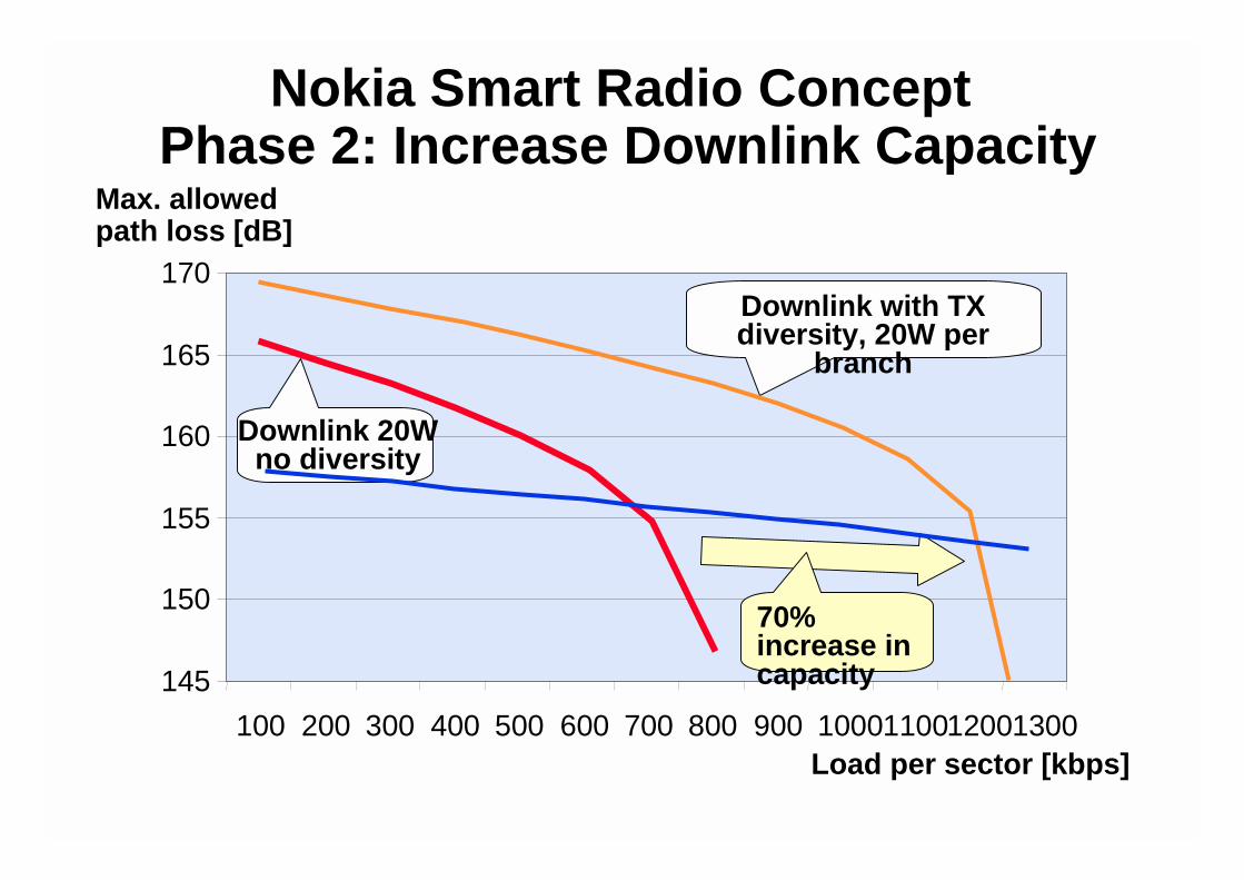
Nokia Smart Radio ConceptPhase 2: Increase Downlink Capacity
145
150
155
160
165
170
100 200 300 400 500 600 700 800 900 1000110012001300Load per sector [kbps]
Max. allowedpath loss [dB]
Downlink 20Wno diversity
Downlink with TXdiversity, 20W per
branch
70%increase incapacity

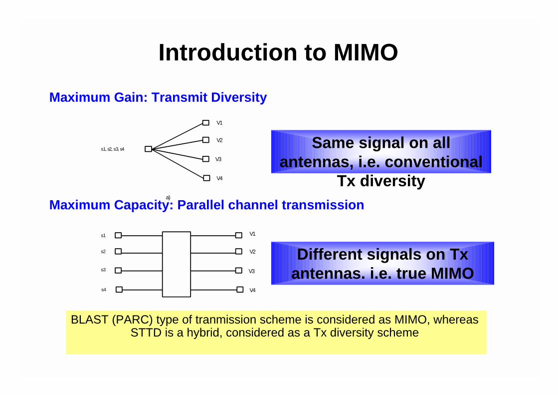
Introduction to MIMO concepts
Reference:
Foschini and Gans, "On limits of wirelesscommunications in a fading environment whenusing multiple antennas", Wireless PersonalCommunications, vol. 6, no.3, 1998
s2
s3
s4
s1
s1, s2, s3, s4
V1
V2
V3
V4
V1
V2
V3
V4
a)
b)
Same signal on allantennas, i.e. conventional
Tx diversity
Different signals on Txantennas. i.e. true MIMO
Maximum Gain: Transmit Diversity
Maximum Capacity: Parallel channel transmission
Introduction to MIMO
BLAST (PARC) type of tranmission scheme is considered as MIMO, whereasSTTD is a hybrid, considered as a Tx diversity scheme
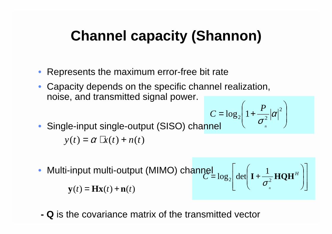
Channel capacity (Shannon)
• Represents the maximum error-free bit rate
• Capacity depends on the specific channel realization,noise, and transmitted signal power.
• Single-input single-output (SISO) channel
• Multi-input multi-output (MIMO) channel
- Q is the covariance matrix of the transmitted vector
��
�
�
��
�
�+= 2
22 1log ασ
n
PC
)()()( tntxty +⋅= α
���
�
���
�
��
�
�
�+= H
n
C HQHI22
1detlog
σ)()()( ttt nHxy +=

Power allocation strategies- Uniform power distribution
• Transmission power has to be properly distributed over theantennas to maximize the capacity
• For unknown channel uniform power distribution over theantennas can be applied
which gives
• For fading channel ergodic capacity can be found byMonte-Carlo simulations
IQTn
P=
���
�
���
�
��
�
�
�+= HT
n
nPC HHI
22
/detlog
σ

Power allocation strategiesWater-filling
• For known channel optimum power distribution using the“water-filling” technique can be applied
• The “water-filling” algorithm can be derived afterconverting the MIMO channel into a set of L parallelchannels using a SVD of the channel matrix
yielding the following optimum power allocationk
nk Kp
λσ 2
−=
Lktntxty kkkk
H
≤≤+==
1)(~)(~)(~ λUDVH

Capacity resultsUncorrelated Rayleigh MIMO channel (I)
0 1 2 3 4 5 6 7 80.9
0.91
0.92
0.93
0.94
0.95
0.96
0.97
0.98
0.99
1Capacity CDFs for uncorrelated flat-freq. Rayleigh channels (21.000000 dB)
Capacity in bits per second per Hertz
Pro
babi
lity(
capa
city
>ab
cisa
)
SISOMIMO(1,2)Unknow n MIMO(2,1)Know n MIMO(2,1)MIMO(1,4)Unknow n MIMO(4,1)Know n MIMO(4,1)

Capacity resultsUncorrelated Rayleigh MIMO channel (II)
0 2 4 6 8 10 12 14 16 18 20 220.9
0.91
0.92
0.93
0.94
0.95
0.96
0.97
0.98
0.99
1Capacity CDFs for uncorrelated flat-freq. Rayleigh channels (21.000000 dB)
Capacity in bits per second per Hertz
Pro
babi
lity(
capa
city
>ab
cisa
)
SISOUnknow n MIMO(2,2)Know n MIMO(2,2)Unknow n MIMO(2,4)Know n MIMO(2,4)Unknow n MIMO(4,2)Know n MIMO(4,2)Unknow n MIMO(4,4)Know n MIMO(4,4)

Capacity resultsFully correlated Rayleigh MIMO channel (I)
0 1 2 3 4 5 6 7 80.9
0.91
0.92
0.93
0.94
0.95
0.96
0.97
0.98
0.99
1Capacity CDFs for correlated flat-freq. Rayleigh channels (21.000000 dB)
Capacity in bits per second per Hertz
Pro
babi
lity(
capa
city
>ab
cisa
)
SISOMIMO(1,2)Unknow n MIMO(2,1)Know n MIMO(2,1)MIMO(1,4)Unknow n MIMO(4,1)Know n MIMO(4,1)
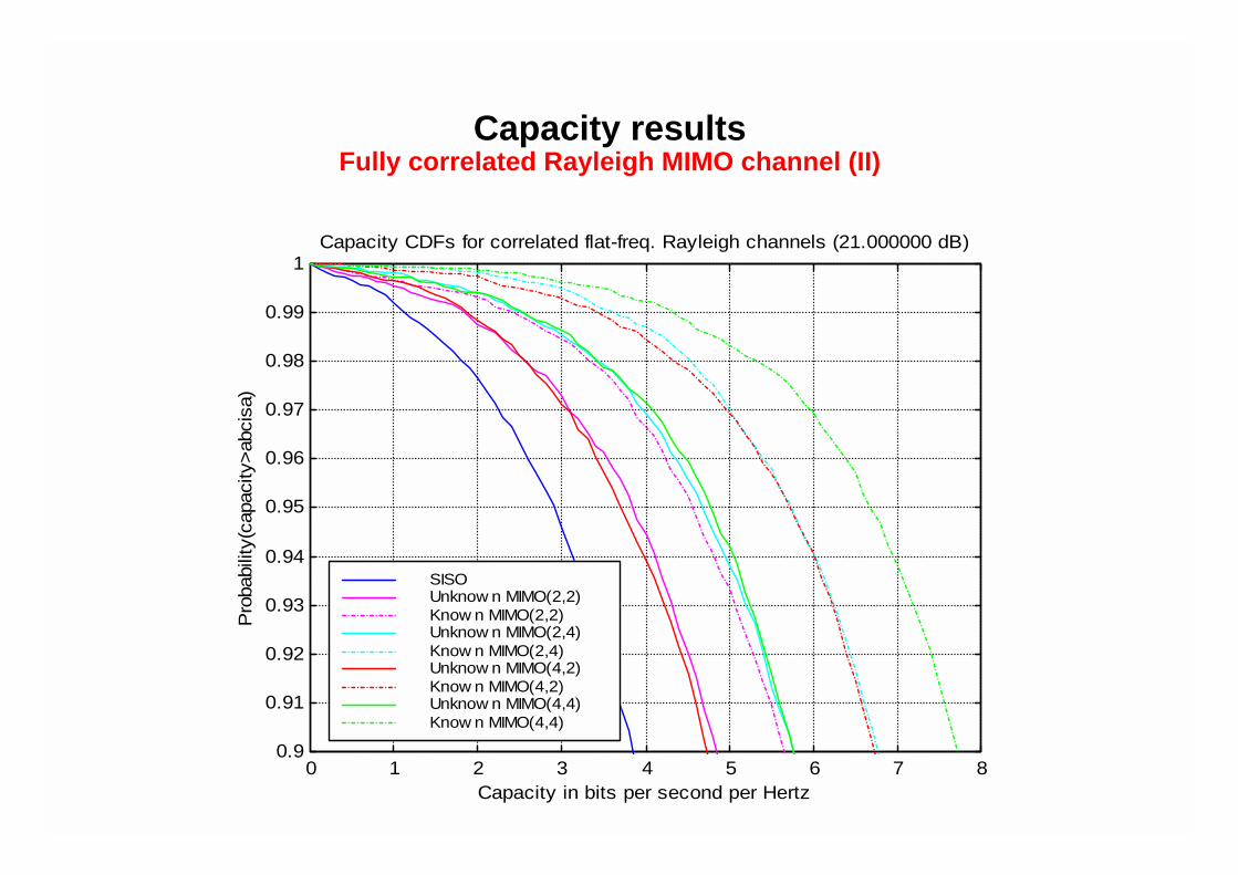
Capacity resultsFully correlated Rayleigh MIMO channel (II)
0 1 2 3 4 5 6 7 80.9
0.91
0.92
0.93
0.94
0.95
0.96
0.97
0.98
0.99
1Capacity CDFs for correlated flat-freq. Rayleigh channels (21.000000 dB)
Capacity in bits per second per Hertz
Pro
babi
lity(
capa
city
>ab
cisa
)
SISOUnknow n MIMO(2,2)Know n MIMO(2,2)Unknow n MIMO(2,4)Know n MIMO(2,4)Unknow n MIMO(4,2)Know n MIMO(4,2)Unknow n MIMO(4,4)Know n MIMO(4,4)

C=log2(1+SNR) [b/s/Hz]
MIMO with N Tx and M Rx antennas, unknown channel:
MIMO versus Rx/Tx Diversity(theoretical)
Spectral efficiency of one channel, no diversity:
Rx & Tx diversity: N Tx and M Rx antennas, known channel:
C=Nlog2(1+SNR*M/N) [b/s/Hz]
M=N=> C= Nlog2(1+SNR) [b/s/Hz]
C=log2(1+SNR*M*N) [b/s/Hz]

MIMO vs. diversity approaches
True MIMO has a theoretical potential at high SNRs, whileconventional Rx schemes are more attractive at low SNRs