communication protocols for body area networks - cap … · communication protocols for body area...
TRANSCRIPT

Communication protocols for
Body Area Networks
M. Maman, D. Miras and L. Ouvry
(CEA-Leti Minatec)
05/12/2012

© CEA. All rights reserved
Communication Protocol for Body Area Networks | 05/12/2012 | 2
FP7-SME-2008-2
System Integration
1. Introduction
2. Wear-a-BAN communication protocols1. Network topology and devices roles
2. Layers description
3. Abstraction layer
4. MAC protocol layer
5. Logical Link Control layer
6. Higher layers
7. Interface between WAB nodes and the PC
3. Wear-a-BAN scenarios and applications
4. Network Demonstrator
5. Conclusions

© CEA. All rights reserved
Communication Protocol for Body Area Networks | 05/12/2012 | 3
FP7-SME-2008-2
System Integration
1. Introduction
2. Wear-a-BAN communication protocols1. Network topology and devices roles
2. Layers description
3. Abstraction layer
4. MAC protocol layer
5. Logical Link Control layer
6. Higher layers
7. Interface between WAB nodes and the PC
3. Wear-a-BAN scenarios and applications
4. Network Demonstrator
5. Conclusions

© CEA. All rights reserved
Communication Protocol for Body Area Networks | 05/12/2012 | 4
FP7-SME-2008-2
CEA Contributions
� CEA is responsible for the development of the communication protocol stack and the profiling (i.e. adaptation of its parameters to end-user scenarios) for applications.
� This protocol enables forwarding of the data coming asynchronously from the various BAN sensors so that individual data transmitted by each is easily identified, received without error and transmitted to a central station for further processing and visualization.
� This support both motional and emotional kind of sensor data, with their respective Quality of Service (QoS) requirements.
� The communication protocol runs onto the Wear-a-BAN SoC and is responsible for transmitting and receiving the user data between the different devices of the network
� CEA have to validate the performance of a network composed of heterogeneous modules from a networking and radio perspective and to optimize the protocol for the Wear-a-BAN chip (WAB SoC)
© CEA. All rights reserved
Communication Protocol for Body Area Networks | 05/12/2012 | 5
FP7-SME-2008-2
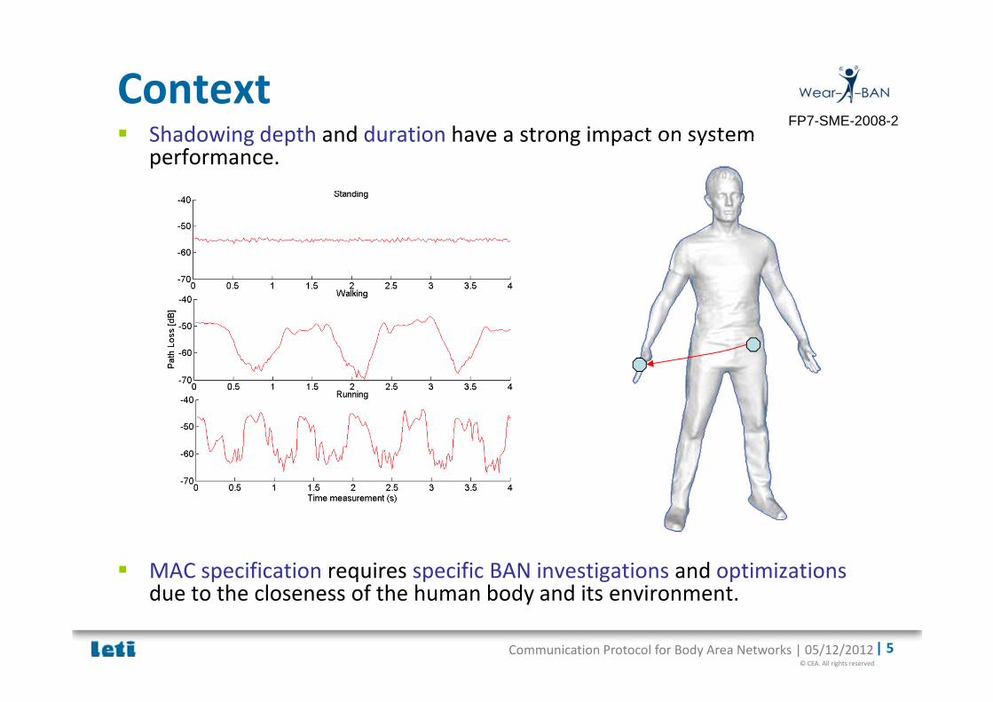
Context� Shadowing depth and duration have a strong impact on system
performance.
� MAC specification requires specific BAN investigations and optimizations due to the closeness of the human body and its environment.

© CEA. All rights reserved
Communication Protocol for Body Area Networks | 05/12/2012 | 6
FP7-SME-2008-2
� To collect multiple real-time motional and emotional sensors
information of nodes at different places of the human body and
to wirelessly transmit it towards dedicated devices, machines or
computers.
� To provide a complete protocol stack from Sensors to End Users
clients:� Design and Optimization of the WAB radio driver for low power and low
latency switch
� Design custom MAC communications protocol for WBAN
� Design of the Logical Link Control layer providing flow control, traffic management and QoS
� Design of the application Scheduler providing for example the frame type, the Remote programming and the Sensor control
� Design the interface between WAB node and the PC
Goals

© CEA. All rights reserved
Communication Protocol for Body Area Networks | 05/12/2012 | 7
FP7-SME-2008-2
� To implement a self organizing adaptive, flexible and low-power
communication protocols for BAN
� Unique : a common protocol architecture for several applications
� Flexible (Network size, topology, communication…)
� Adapted to BAN
� Guaranteeing good QoS (reliability, latency,…)
• Dynamic and Automatic relaying mechanisms mitigating the shadowing
impact on PER
� Optimized low power consumption for a long autonomy
� Providing network functionalities (association, self-organizing, data collection…)
� Transparent for the application thanks to several profiles
• Autonomously and dynamically adaptive
• Trade off between QoS and energy consumption
• Adapted to several applications
• Adapted to heterogeneous traffics
Goals

© CEA. All rights reserved
Communication Protocol for Body Area Networks | 05/12/2012 | 8
FP7-SME-2008-2
System Integration
1. Introduction
2. Wear-a-BAN communication protocols1. Network topology and devices roles
2. Layers description
3. Abstraction layer
4. MAC protocol layer
5. Logical Link Control layer
6. Higher layers
7. Interface between WAB nodes and the PC
3. Wear-a-BAN scenarios and applications
4. Network Demonstrator
5. Conclusions

© CEA. All rights reserved
Communication Protocol for Body Area Networks | 05/12/2012 | 9
FP7-SME-2008-2
� Network topology
� Star mesh hybrid topology
� The approach is to base the Wear-A-BAN MAC specifications
on the IEEE 802.15.4/IEEE 802.15.6 standards with these main
deviations:
� Support for peer to peer communication, whereas 802.15.4 requires mediation
from the coordinator to allow it.
� Systematic usage of guaranteed time slots for data transmissions.
� Specification of the relaying procedure.
� Dedicated time slots for monitoring and allocation request.
� Simplification of association and transactions to allow very low complexity
implementations.
� Simplification of initialization procedures.
� Adapt to Body Area Networks
2.1. Network topology and devices roles

© CEA. All rights reserved
Communication Protocol for Body Area Networks | 05/12/2012 | 10
FP7-SME-2008-2
2.1. Network topology and devices roles
� Device roles� Coordinator
� Sends beacon for synchronization and Superframe management
� Accepts node associations
� Manages allocated slots for the different flows.
� Central node
� Connected to the PC
� Collects the data from different Sensors nodes.
� Sensors nodes
� Synchronize on the beacon
� Request to the coordinator an association and a short address
� Request to the coordinator GTS slots.

© CEA. All rights reserved
Communication Protocol for Body Area Networks | 05/12/2012 | 11
FP7-SME-2008-2
2.2. Layers Description
USB JTAG KEY WAB
PC
Application framer
Application
UART framer
FTDI (UART to USB)
Driver (USB to COM)
wrapper (COM to UDP)
Remote Programming
Client
Motion Sensor Client
Emotion Sensor Client
…
WAB node
Abstraction Layer
MAC
LLC
WAB Sensors WAB Radio
Remote Programming …
WAB Timer

© CEA. All rights reserved
Communication Protocol for Body Area Networks | 05/12/2012 | 12
FP7-SME-2008-2
2.3. Abstraction Layer
USB JTAG KEY WAB
PC
Application framer
Application
UART framer
FTDI (UART to USB)
Driver (USB to COM)
wrapper (COM to UDP)
Remote Programming
Client
Motion Sensor Client
Emotion Sensor Client
…
WAB node
Abstraction Layer
MAC
LLC
WAB Sensors WAB Radio
Remote Programming …
WAB Timer
© CEA. All rights reserved
Communication Protocol for Body Area Networks | 05/12/2012 | 13
FP7-SME-2008-2
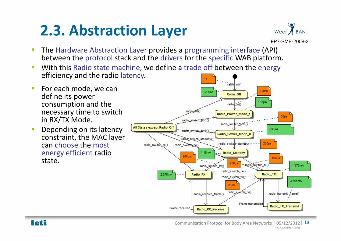
2.3. Abstraction Layer
� For each mode, we can define its power consumption and the necessary time to switch in RX/TX Mode.
� Depending on its latency constraint, the MAC layer can choose the most energy efficient radio state.
� The Hardware Abstraction Layer provides a programming interface (API) between the protocol stack and the drivers for the specific WAB platform.
� With this Radio state machine, we define a trade off between the energyefficiency and the radio latency.

© CEA. All rights reserved
Communication Protocol for Body Area Networks | 05/12/2012 | 14
FP7-SME-2008-2
2.4. MAC protocol layer
USB JTAG KEY WAB
PC
Application framer
Application
UART framer
FTDI (UART to USB)
Driver (USB to COM)
wrapper (COM to UDP)
Remote Programming
Client
Motion Sensor Client
Emotion Sensor Client
…
WAB node
Abstraction Layer
MAC
LLC
WAB Sensors WAB Radio
Remote Programming …
WAB Timer

© CEA. All rights reserved
Communication Protocol for Body Area Networks | 05/12/2012 | 15
FP7-SME-2008-2
2.4. MAC protocol layer
� The Medium Access Control (MAC) Layer provides channel access control mechanisms to several communicating devices.
� The MAC layer is responsible for:
� The network formation
� The association and disassociation of devices to the network,
� The maintenance of the network
� Manage the list of the node in the BAN
� The management of the access to the radio channel.
� A TDMA, centralized and beacon based protocol, inspired from the IEEE802.15.4 standard and, more recently, from the IEEE802.15.6 standard.
� A dedicated format of the superframe delimited by beacons, with CAP, PAP, CFP and inactive periods
� The management of the traffic:
� Traffic allocation/deallocation and expiration
� Acknowledgment and retransmission policies
� Time to live
� Data relaying
� Manage the duplicate data
�

© CEA. All rights reserved
Communication Protocol for Body Area Networks | 05/12/2012 | 16
FP7-SME-2008-2
2.4. MAC protocol layer
� Beacon Period: Dedicated to the coordinator. Each node can synchronize and update its knowledge of the BAN
� Indicator Period: Each device has an attributed Poll minislot for sending back ACK to beacon. During this period, each node can advertise the coordination and other BAN nodes for neighbour discovery, relaying functionalities…
� GTS Period: Guaranteed time slots dedicated to the report of data to the coordinator.
� PAP+CAP: During these Periods slotted ALOHA access i.e. with slot allocation. With the split of the CAP, emergency traffic is protected from control traffic.
� Inactive part: Each node can switch off their radio and save energy.
CAPPAPBeaconperiod
GTS Inactive PartPoll Slot

© CEA. All rights reserved
Communication Protocol for Body Area Networks | 05/12/2012 | 17
FP7-SME-2008-2
2.4. MAC protocol layer� MAC functionalities
� Starting a BAN: The coordinator begins operating the BAN and using a
new superframe configuration
� Beacon generation: Generate and transmit beacon frames
� Beacon Synchronization: Devices can get synchronized by receiving and
decoding the beacon
� Association Procedure:
� Once synchronized, a device requests to the coordination an association
and its short address.
� Disassociation Procedure:
� A device can request to the coordination a disassociation when it missed
MAC_MAX_MISSED_BEACON beacons
� A coordination can force a disassociation when it missed
MAC_ALIVE_NODE_CNT poll node packet
� Poll Period: During this period, each device sends back a poll node
packet to the coordinator indicating its presence.

© CEA. All rights reserved
Communication Protocol for Body Area Networks | 05/12/2012 | 18
FP7-SME-2008-2
2.4. MAC protocol layer
� Relaying Procedure
� During the Poll period, each device has an attributed poll slot for
sending back an poll notification to all nodes in the BAN.
� Each device listens to the poll slots and uses the channel reciprocity.
The poll packet reception will define the instantaneous reliability of a
link.
� In order to select the route (direct or relayed), the originator compares
the reliability of the link with a threshold.
� If the Received Signal Strength Indicator (RSSI) of Recipient-Originator link
is under the threshold, the direct route is selected.
� If the RSSI of Recipient-Originator link is not under the threshold, the
originator selects the route with the best reliability i.e. the direct route of
the relayed route with the best relay.
=> A dynamic relaying table is automatically built depending on the quasi
instantaneous shadowing effect.

© CEA. All rights reserved
Communication Protocol for Body Area Networks | 05/12/2012 | 19
FP7-SME-2008-2
2.5. Logical Link Control Layer
USB JTAG KEY WAB
PC
Application framer
Application
UART framer
FTDI (UART to USB)
Driver (USB to COM)
wrapper (COM to UDP)
Remote Programming
Client
Motion Sensor Client
Emotion Sensor Client
…
WAB node
Abstraction Layer
MAC
LLC
WAB Sensors WAB Radio
Remote Programming …
WAB Timer

© CEA. All rights reserved
Communication Protocol for Body Area Networks | 05/12/2012 | 20
FP7-SME-2008-2
2.5. Logical Link Control Layer
� The Logical Link Control (LLC) sublayer provides an interface between upper sublayers (e.g. Application layer) and the MAC data communication protocol sublayer.
� The LLC provides
� flow control of data to MAC sublayer
� Buffer management mechanisms
� Traffic (Bandwidth)
� Permanent Traffic: permanent traffic set up when the connection is established.
� Switched Traffic: Set up and released on demand via a procedures.
� Quality of service
� A connection (an LLC flow) must be established before any packets are sent. Each flow category is defined by associated traffic, priority and QoS parameters.
� Several flows can be managed simultaneously by the LLC depending on the
traffic generated
⇒ This scheme permits to a higher flow priority to used bandwidth to a lower flow priority (e.g. emergency data used bandwidth to monitoring data)

© CEA. All rights reserved
Communication Protocol for Body Area Networks | 05/12/2012 | 21
FP7-SME-2008-2
2.5. Logical Link Control Layer
� A specific flow has to define a flow for each WAB scenario with one or two profiles.
� When the profile1 does not respect the requirement (e.g. loss rate), the flow can switch to Profile2 (Better Reliability but higher power consumption)
� Flow� Type of flows
� Network control
� Remote programming
� Emergency
� Voice
� Monitoring
� Logging
� Best effort
� Excellent effort
� Recipient address
� Packet rate in ms
� % of loss Rate Acceptable
� Time To Live: time before discarding the data
� Packet Rate statistics: useful to change profile
� Profile 1
� Profile 2

© CEA. All rights reserved
Communication Protocol for Body Area Networks | 05/12/2012 | 22
FP7-SME-2008-2
2.5. Logical Link Control Layer
� In Monitoring category, two profiles have been defined for data reporting: � In the first profile, the device transmits its data in allocated slots of the CFP and waits for an
immediate acknowledgment.
� If the data is not correctly received, it can send again this data in the CAP period of the same superframe.
� If the quality of service configurable by the application is not respected, the monitoring flow can switch to the second profile with relaying functionalities.

© CEA. All rights reserved
Communication Protocol for Body Area Networks | 05/12/2012 | 23
FP7-SME-2008-2
2.6. Higher Layers
USB JTAG KEY WAB
PC
Application framer
Application
UART framer
FTDI (UART to USB)
Driver (USB to COM)
wrapper (COM to UDP)
Remote Programming
Client
Motion Sensor Client
Emotion Sensor Client
…
WAB node
Abstraction Layer
MAC
LLC
WAB Sensors WAB Radio
Remote Programming …
WAB Timer
© CEA. All rights reserved
Communication Protocol for Body Area Networks | 05/12/2012 | 24
FP7-SME-2008-2
2.6. Higher Layers
� The application framer layer directs the received packet from the LLC layer towards the specified application module.
� Definition of Several application modules for each scenarios
� The central node is able to program WAB nodes using the RF. Remote programming is an application using lower layers to transmit its frame.
� UARTs driver has been optimized with multi-UART functionality in order to: � support higher data rate between the central node and the PC. The complete
chain throughput is up to 20Ko/s (Radio, MAC, UART, UDP).
� direct the received packet from the UART module towards the specified module. The UART framer adds a terminator at the end of the frame in order to delimit the frame and converts binary hexadecimal to ASCII format.

© CEA. All rights reserved
Communication Protocol for Body Area Networks | 05/12/2012 | 25
FP7-SME-2008-2
USB JTAG
2.7. Interface between WAB node and the PC
RFD MAC stack
FFD MAC stack
Sensor node application
Central node application
UART
FTDI (UART to USB)
Driver (USB to COM)
wrapper (COM to UDP)
Remote Programming
Client
Sensor node
Central node
PC
Motion Sensor Client
Emotion Sensor Client
…
� The path between the
application Layer of the
central node and the PC is
the following:
� The FTDI interfaces the UART
to the USB port (in USB JTAG).
� In the PC, we interface the USB
port with the COM Port using
the driver.
� In the PC, we can launch the
Wrapper program which
converts the COM Port
Protocol to UDP Port Protocol
and sends it to the
corresponding client.
� The GUI client can interface
using UDP protocol and WAB
frame format

© CEA. All rights reserved
Communication Protocol for Body Area Networks | 05/12/2012 | 26
FP7-SME-2008-2
2.6. Interface between WAB node and the PC
Frame Type Timestamp ACC_X ACC_Y ACC_Z G_X G_Y G_Z M_X M_Y M_Z Node ID
8 bits 24 bits 16 bits 16 bits 16 bits 16 bits 16 bits 16 bits 16 bits 16 bits 16 bits 8 bits
� The frame_type values are:
� Log 0x0x
� Remote Programming 0x1x
� Network management 0x2x
� Motion Data 0x4x
� Emotional Data 0x5x
� RSSI 0x8x
� Accelerometer 0x41
� Gyrometer 0x42
� Accelerometer and Gyrometer 0x43
� Magnetometer 0x44
� Accelerometer and Magnetometer 0x45
� Gyrometer and Magnetometer 0x46
� Accelerometer, Gyrometer and Magnetometer 0x47
� Energy Expenditure 0x48
�…

© CEA. All rights reserved
Communication Protocol for Body Area Networks | 05/12/2012 | 27
FP7-SME-2008-2
System Integration
1. Introduction
2. Wear-a-BAN communication protocols1. Network topology and devices roles
2. Layers description
3. Abstraction layer
4. MAC protocol layer
5. Logical Link Control layer
6. Higher layers
7. Interface between WAB nodes and the PC
3. Wear-a-BAN scenarios and applications
4. Network Demonstrator
5. Conclusions

© CEA. All rights reserved
Communication Protocol for Body Area Networks | 05/12/2012 | 28
FP7-SME-2008-2
3. WAB Scenarios and Applications� Application A: Robotics based rehabilitation
� The objective of this scenario is to detect the amplitude of movements in
an arm. This is achieved by placing a series of movement sensors in a
textile base in the form of a wearable sleeve.
Coordinator
Node
� 4 Motion Nodes
� Measure the angular motion (gyroscope),
the linear acceleration (accelerometer), and
the orientation (magnetometer).
� Transmit the motion sensor data to the
Central Node
� 1 Central node and BAN coordinator
� Manage the BAN.
� Receive all sensors information and deliver
it to the PC central unit.
� Define Adapted Profile
� Type of flows = Monitoring
� Packet rate = 20ms i.e. 50Hz
� % of loss Rate Acceptable= 10%
� Time To Live= 40ms

© CEA. All rights reserved
Communication Protocol for Body Area Networks | 05/12/2012 | 29
FP7-SME-2008-2
3. WAB Scenarios and Applications� Application B : Daily life physical activity monitoring in Real Time
� In this scenario, the nodes, and their communication protocol, have to support
biofeedback functionalities which impact their real-time capabilities and technical
specifications.
� The expired monitoring data is retransmitted later using logging mode. No motion
sensor data is lost.
Coordinator
Node
� 3 Motion Nodes
� Measure the angular motion (gyroscope), the
linear acceleration (accelerometer), and the
orientation (magnetometer).
� Transmit the motion sensor data to the Central
Node in Real Time.
� Motion sensor data, which not respected
specifications, are retransmitted in logging mode.
� 1 Central node and BAN coordinator
� Manage the BAN.
� Receive all sensors information and deliver it to
the PC central unit.

© CEA. All rights reserved
Communication Protocol for Body Area Networks | 05/12/2012 | 30
FP7-SME-2008-2
3. WAB Scenarios and Applications� Application B : Daily life physical activity monitoring in Real Time
� In this scenario, the nodes, and their communication protocol, have to support
biofeedback functionalities which impact their real-time capabilities and technical
specifications.
� The expired monitoring data is retransmitted later using logging mode. No motion
sensor data is lost.
Coordinator
Node
� Flow for monitoring for real time mode
� Packet rate = 66ms i.e. 15Hz
� % of loss Rate Acceptable= 10%
� Time To Live= 100ms
� Flow for logging for expired monitoring data
� % of loss Rate Acceptable= 0%
� Time To Live= Unexpired

© CEA. All rights reserved
Communication Protocol for Body Area Networks | 05/12/2012 | 31
FP7-SME-2008-2
3. WAB Scenarios and Applications� Application C: Daily life physical activity monitoring
� In this scenario, each node has to collectively provide activity recognition and
energy expenditure information without a constant connection to the central
node and PC. In case of autonomous work, all information regarding physical
activity is to be stored in a local memory of the BAN coordinator and sent to the
PC once the connection is re-established with the Central node.
� 2 Motion Nodes
� Measure the linear acceleration (accelerometer).
� Compute activity index every second.
� Transmit the energy expenditure to the coordinator.
� 1 Motion Nodes acting as BAN coordinator
� Manage the BAN.
� Receive all sensors information and stored
in a local memory.
� When the Central node is associated to the BAN,
transmit data stored to the Central node.
� 1 Central Node
� Receive all sensors information and deliver it to the
PC central unit.
BAN Coordinator
Central Node
Motion Node

© CEA. All rights reserved
Communication Protocol for Body Area Networks | 05/12/2012 | 32
FP7-SME-2008-2
3. WAB Scenarios and Applications� Application D: Gaming
� This scenario presents a game that merge singing and dancing performance. The
singing performance is score by the use of an Emotion node (microphone
sensor), while the dancing performance is done by the use of motion nodes
(several movement sensor).
Central Node and BAN Coordinator
Motion Node
Emotion Node
� 5 Motion Nodes
� Measure the angular motion (gyroscope), the
linear acceleration (accelerometer), and the
orientation (magnetometer).
� Transmit the motion sensor data to the
Central Node
� 1 Emotion Node
� The microphone collects the audio.
� Transmit the audio stream to the Central
Node.
� 1 Central node and BAN coordinator
� Manage the BAN.
� Receive all sensors information and deliver it
to the PC central unit.

© CEA. All rights reserved
Communication Protocol for Body Area Networks | 05/12/2012 | 33
FP7-SME-2008-2
3. WAB Scenarios and Applications� Application D: Gaming
� This scenario presents a game that merge singing and dancing performance. The
singing performance is score by the use of an Emotion node (microphone
sensor), while the dancing performance is done by the use of motion nodes
(several movement sensor).
� Flow Monitoring for motional node
� Packet rate = 100ms i.e. 10Hz
� % of loss Rate Acceptable= 10%
� Time To Live= 100ms
� Flow Voice for emotional node
� Packet rate = 5 kHz => 10kBytes/s
� % of loss Rate Acceptable= 10%
� Time To Live= 16msCentral Node and BAN Coordinator
Motion Node
Emotion Node

© CEA. All rights reserved
Communication Protocol for Body Area Networks | 05/12/2012 | 34
FP7-SME-2008-2
System Integration
1. Introduction
2. Wear-a-BAN communication protocols1. Network topology and devices roles
2. Layers description
3. Abstraction layer
4. MAC protocol layer
5. Logical Link Control layer
6. Higher layers
7. Interface between WAB nodes and the PC
3. Wear-a-BAN scenarios and applications
4. Network Demonstrator
5. Conclusions

© CEA. All rights reserved
Communication Protocol for Body Area Networks | 05/12/2012 | 35
FP7-SME-2008-2
35
4. Network Demonstrator
Central node
WAB Node
� Network Composition: � 1 Central Node (coordinator) connected to the PC.
� 5 WAB Nodes (device) embedded in the body.
� 1 Headset Node with microphone.
� 3 clients:
� 2 Graphical User Interface in the PC.
� 1 Java client for audio.
Emotion Node

© CEA. All rights reserved
Communication Protocol for Body Area Networks | 05/12/2012 | 36
FP7-SME-2008-2
4. Network Demonstrator
� Traffic flows: � Network Control: To define the position of the node.
� Best Effort: To measure the quality of the link between device.
� Excellent Effort: To manage the motion capture.
� Voice: To manage audio stream.

© CEA. All rights reserved
Communication Protocol for Body Area Networks | 05/12/2012 | 37
FP7-SME-2008-2
4. Network Demonstrator
� Traffic flows: � Network Control: To define the position of the node.
� The device sends to the Central node the position in the network topology
when it is associated to the BAN.
Central node
WAB Node

© CEA. All rights reserved
Communication Protocol for Body Area Networks | 05/12/2012 | 38
FP7-SME-2008-2
4. Network Demonstrator
� Traffic flows: � Best Effort: To measure the quality of the link between device.
� The Device send neighbours RSSI information with multicast packet. All
devices measure the link quality from this packet to reach the originator.
� The Central node collect the neighbours RSSI tables from all the device
associated to the BAN.
Central node
WAB Node
RSSI Table

© CEA. All rights reserved
Communication Protocol for Body Area Networks | 05/12/2012 | 39
FP7-SME-2008-2
4. Network Demonstrator
� Traffic flows: � Excellent Effort: To manage the motion capture.
� The device provide periodic motion sensor feedback to the Central Node.
Central node
WAB Node

© CEA. All rights reserved
Communication Protocol for Body Area Networks | 05/12/2012 | 40
FP7-SME-2008-2
4. Network Demonstrator
� Traffic flows: � Voice: To manage audio stream.
� The headset device provide audio stream to the Central Node
Central node
Emotion Node

© CEA. All rights reserved
Communication Protocol for Body Area Networks | 05/12/2012 | 41
FP7-SME-2008-2
4. Network Demonstrator
� Network Topology :
� Collect network management and
topology information.
� Motion sensor capture :
� Collect motion sensor data of the
targeted node.

© CEA. All rights reserved
Communication Protocol for Body Area Networks | 05/12/2012 | 42
FP7-SME-2008-2
System Integration
1. Introduction
2. Wear-a-BAN communication protocols1. Network topology and devices roles
2. Layers description
3. Abstraction layer
4. MAC protocol layer
5. Logical Link Control layer
6. Higher layers
7. Interface between WAB nodes and the PC
3. Wear-a-BAN scenarios and applications
4. Network Demonstrator
5. Conclusions
© CEA. All rights reserved
Communication Protocol for Body Area Networks | 05/12/2012 | 43
FP7-SME-2008-2
� A BAN is a self-organizing network at the human body scale
which consists in a collection of smart, low-power, hardware-
constrained, miniaturized and heterogeneous wireless devices
attached to (or implanted into) a moving body.
� With respect to state-of-the-art, the Wear-a-BAN protocol is a
very interesting piece of technology with respect to
existing/emerging WBAN protocols since it provides all features
to potentially map most the identified applications in the BAN
area while offering the right level of performance. It also
provides innovative features like physical layer profiling,
dynamic relaying and traffic flows arbitration to optimize QoS
and/or battery lifetime depending on user needs.
5. Conclusions

© CEA. All rights reserved
Communication Protocol for Body Area Networks | 05/12/2012 | 44
FP7-SME-2008-2
5. Conclusions
� Antennas design according to the application� Trade-off between efficiency and size in the presence of human body
� Time-variant on-body channel, Space-time correlation properties