common test equipment and logical troubleshooting 3 and 2 chapter 13... · common test equipment...
TRANSCRIPT
CHAPTER 13
COMMON TEST EQUIPMENT
AND LOGICAL TROUBLESHOOTING
In preceding chapters we have presented the basic operating principles of missile launching systems, and explained how they fit into the shipboard missile weapons system. But an understanding of the theory of operation is only part of the knowledge you need for successful maintenance of launching system equipment. You must be able to use test equipment and to troubleshoot. In this chapter we will cover test equipment used to measure electrical quantities, and the basic techniques for troubleshooting electronic circuitry. The device that you will use most frequently in your maintenance tasks is the meter. For this reason, we shall first review meters before we discuss other test equipment and troubleshooting techniques. You will find a more complete coverage of meters in chapter 15 of Basic Electricity, NavPers 10086-B.
REVIEW OF METER OPERATION We want to emphasize that a thorough understanding of the construction, operation, and limitations of electrical measuring instruments, coupled with the theory of circuit operation, is essential in serving and maintaining electrical equipment. Remember that the best and most expensive measuring instrument is of NO use to the man who does not know what he is measuring or what the readings indicate. The three types of meters that you will most often use are ammeter, ohmmeter, and voltmeter. It is well to pay special attention to each application in this review. AMMETER The ammeter is used to measure current. The GMM uses the ammeter to acquire further information while performing an operational check on a malfunctioning launching system to further localize the malfunction to a specific unit. The
ammeter must always be placed in series with the circuit to be measured. The ammeter consists of a basic meter movement and a combination of shunt resistors in parallel with it. The ammeters used in missile systems test equipment and component test sets usually are panel-mounted instruments. In these applications they can be used to detect the current drain of the major electrical circuits and thus provide a valuable first step in finding trouble. When ammeters are not included as parts of the equipment, current measurements can be made only after the circuit wiring has been opened and the meter inserted in series with a suspected part. A multiposition switch or a series of pin jacks allows the use of various shunt resistors to give different current ranges. When using an ammeter, always have the meter on the highest range before connecting it into a circuit. OHMMETER The ohmmeter is widely used by GMM's in making resistance measurements and continuity checks. You will find wide use for this instrument in checking cables and locating malfunctioning components in electrical circuits. The ohmmeter consists of a basic meter movement connected as an ammeter, a voltage source, and one or more resistors used to adjust the current through the meter movement. The meter must be adjusted for "zero resistance" prior to making resistance measurements. MAKE SURE YOU DON'T USE AN OHMMETER ON AN ENERGIZED CIRCUIT. If you do, the meter will make smoke and burn out. The theory and construction of the series type and the shunt type ohmmeters are discussed in Basic Electricity, NavPers 10086-B, which also describes a more specialized type of instrument, the megohmmeter, or meggar. The use of resistance checks for locating defective parts in electronic circuits is somewhat similar to the process of voltage checking. As with the voltmeter, the observed values are compared with the normal
423
GUNNER'S MATE M 3 & 2
values given in the equipment manual to identify the malfunctioning part. This method, like voltage checking, is most effective after the trouble has been isolated to a single stage. VOLTMETER The voltmeter uses the basic meter movement with a high resistance in series. The value of this series resistance is determined by the current necessary for full-scale deflection of the meter, and the voltage being measured. Because the current is directly proportional to the voltage applied, the scale can be calibrated directly in volts for a fixed series resistance. The sensitivity of voltmeters is given in ohms per volt, and may be determined by dividing the resistance of the meter, plus the series resistance, by the full-scale reading in volts. This is the same as saying that the sensitivity is equal to the reciprocal of the current (in amperes). Thus, the sensitivity of a 100-microampere movement is the reciprocal of 0.0001 ampere, or 10,000 ohms per volt. The sensitivity of the meter depends on the strength of the permanent magnet field and the weight of the moving coil. The sensitivity of a voltmeter is an indication of how accurately it measures voltages in a circuit. In many cases, a sensitivity of 1,000 ohms per volt is satisfactory; however, if the circuit in which the voltage is being measured has high resistance, a greater sensitivity is required for accuracy. The higher the sensitivity rating, the higher the resistance in the meter branch of the circuit, and the less serious the effect of shunting the circuit. If a meter of low ohms per volt is used to measure the voltage in a high resistance circuit, the effect of the meter shunting load being measured will result in an inaccurate reading. Thus, the higher the sensitivity, the more accurate the reading. Like the ammeter and ohmmeter, the voltmeter normally utilizes several resistors with a switching arrangement to permit multirange operation. Be sure to set the selector switch for maximum voltage range before connecting the meter to an energized circuit. MULTIMETERS During troubleshooting, you, as a technician are often required to measure voltage, current, and resistance. To eliminate the necessity of obtaining three or more meters, you will use
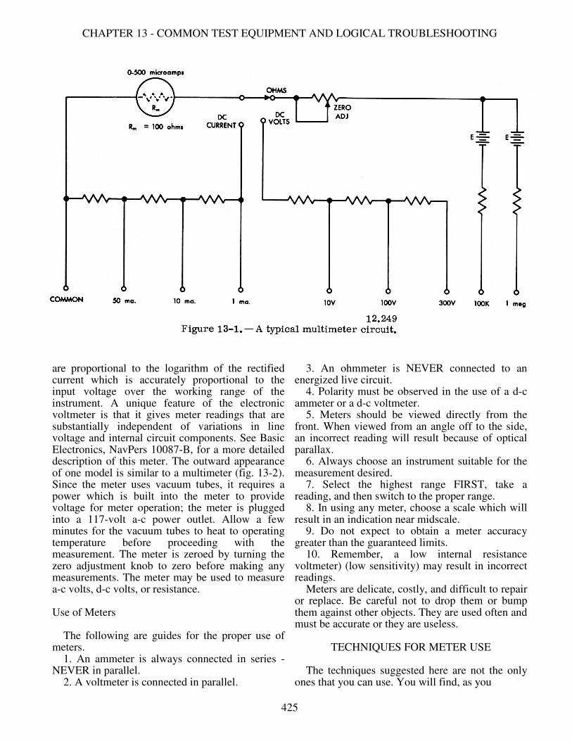
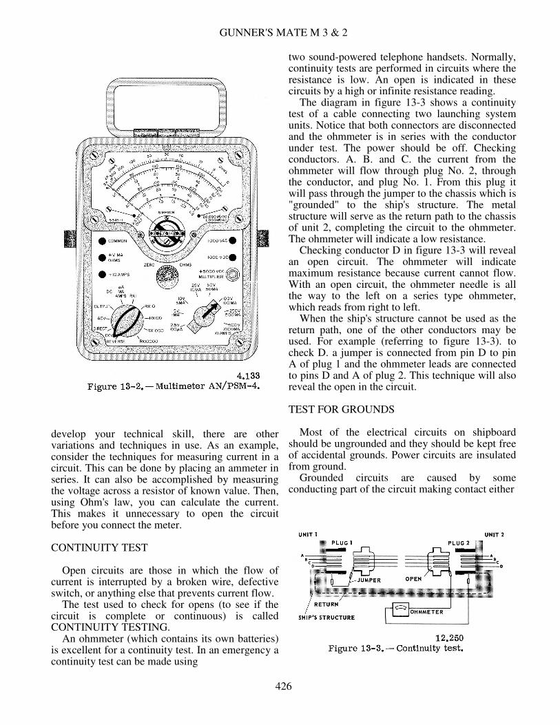
a multimeter. The multimeter combines a voltmeter, ammeter, and ohmmeter in one unit. It includes all the necessary switches, jacks, and additional devices. By proper arrangement of parts, the multimeter can be built into a small, compact unit utilizing one meter movement; capable of being switched to different ranges. A typical multimeter circuit is shown in figure 13-1. A three-range milliammeter, a three-range voltmeter with a sensitivity of 2,000 ohms per volt, and a two-range ohmmeter are combined in this circuit. A 0-500 microampere meter movement with a resistance of 100 ohms is the basic meter movement for the multimeter. The AN/PSM-4 is a multimeter commonly used in the Navy. There are three controls on the face (fig. 13-2) of the instrument. The 10 position rotary switch in the lower left corner is used as a function selector. (Five of these positions set up ohmmeter connections within the instrument. For these resistance positions, the function selector also acts as a range selector.) The 8-position switch in the lower righthand corner selects ranges of voltage and current. The ZERO-OHMS control is continuously variable and is used to adjust the meter circuit sensitivity to compensate for battery aging in the ohmmeter circuits. It is used to set the pointer at full scale (indicating zero ohms) when the function selector is set at any resistance range and the test probes are shorted together. Prior to using the meter for measuring volts, amps, or ohms, be sure that the meter movement is on zero. Observe the meter face, making sure that the indicating pointer is pointing to the left hand side of the meter, and the pointer is on zero for volts, and infinity for ohms. If the pointer is not on zero, make correction by the turn screw head located at the base of the meter face. VACUUM TUBE VOLTMETER The ordinary voltmeter is practically useless for measuring voltages in high-impedance circuits. The electronic voltmeter is a highly sensitive instrument for accurately measuring a-c voltages from 250 microvolts to 500 volts, within a wide frequency range. The meter consists essentially of a multistage amplifier terminated by two crystal diodes, connected in a bridge circuit, and a meter movement to indicate rectified current. One such meter is designed with shaped pole pieces so that the indications
424
CHAPTER 13 - COMMON TEST EQUIPMENT AND LOGICAL TROUBLESHOOTING
are proportional to the logarithm of the rectified current which is accurately proportional to the input voltage over the working range of the instrument. A unique feature of the electronic voltmeter is that it gives meter readings that are substantially independent of variations in line voltage and internal circuit components. See Basic Electronics, NavPers 10087-B, for a more detailed description of this meter. The outward appearance of one model is similar to a multimeter (fig. 13-2). Since the meter uses vacuum tubes, it requires a power which is built into the meter to provide voltage for meter operation; the meter is plugged into a 117-volt a-c power outlet. Allow a few minutes for the vacuum tubes to heat to operating temperature before proceeding with the measurement. The meter is zeroed by turning the zero adjustment knob to zero before making any measurements. The meter may be used to measure a-c volts, d-c volts, or resistance. Use of Meters The following are guides for the proper use of meters. 1. An ammeter is always connected in series - NEVER in parallel. 2. A voltmeter is connected in parallel.
3. An ohmmeter is NEVER connected to an energized live circuit. 4. Polarity must be observed in the use of a d-c ammeter or a d-c voltmeter. 5. Meters should be viewed directly from the front. When viewed from an angle off to the side, an incorrect reading will result because of optical parallax. 6. Always choose an instrument suitable for the measurement desired. 7. Select the highest range FIRST, take a reading, and then switch to the proper range. 8. In using any meter, choose a scale which will result in an indication near midscale. 9. Do not expect to obtain a meter accuracy greater than the guaranteed limits. 10. Remember, a low internal resistance voltmeter) (low sensitivity) may result in incorrect readings. Meters are delicate, costly, and difficult to repair or replace. Be careful not to drop them or bump them against other objects. They are used often and must be accurate or they are useless.
TECHNIQUES FOR METER USE The techniques suggested here are not the only ones that you can use. You will find, as you
425
GUNNER'S MATE M 3 & 2
develop your technical skill, there are other variations and techniques in use. As an example, consider the techniques for measuring current in a circuit. This can be done by placing an ammeter in series. It can also be accomplished by measuring the voltage across a resistor of known value. Then, using Ohm's law, you can calculate the current. This makes it unnecessary to open the circuit before you connect the meter. CONTINUITY TEST Open circuits are those in which the flow of current is interrupted by a broken wire, defective switch, or anything else that prevents current flow. The test used to check for opens (to see if the circuit is complete or continuous) is called CONTINUITY TESTING. An ohmmeter (which contains its own batteries) is excellent for a continuity test. In an emergency a continuity test can be made using
two sound-powered telephone handsets. Normally, continuity tests are performed in circuits where the resistance is low. An open is indicated in these circuits by a high or infinite resistance reading. The diagram in figure 13-3 shows a continuity test of a cable connecting two launching system units. Notice that both connectors are disconnected and the ohmmeter is in series with the conductor under test. The power should be off. Checking conductors. A. B. and C. the current from the ohmmeter will flow through plug No. 2, through the conductor, and plug No. 1. From this plug it will pass through the jumper to the chassis which is "grounded" to the ship's structure. The metal structure will serve as the return path to the chassis of unit 2, completing the circuit to the ohmmeter. The ohmmeter will indicate a low resistance. Checking conductor D in figure 13-3 will reveal an open circuit. The ohmmeter will indicate maximum resistance because current cannot flow. With an open circuit, the ohmmeter needle is all the way to the left on a series type ohmmeter, which reads from right to left. When the ship's structure cannot be used as the return path, one of the other conductors may be used. For example (referring to figure 13-3). to check D. a jumper is connected from pin D to pin A of plug 1 and the ohmmeter leads are connected to pins D and A of plug 2. This technique will also reveal the open in the circuit. TEST FOR GROUNDS Most of the electrical circuits on shipboard should be ungrounded and they should be kept free of accidental grounds. Power circuits are insulated from ground. Grounded circuits are caused by some conducting part of the circuit making contact either
426

CHAPTER 13 - COMMON TEST EQUIPMENT AND LOGICAL TROUBLESHOOTING
directly or indirectly with the metallic structure of the ship. Grounds may have many causes. The two most common are the fraying of insulation from a wire allowing the bare wire to come in contact with the metal ground, and moisture soaked insulation. Grounds usually are indicated by blown fuses or tripped circuit breakers. Blown fuses or tripped circuit breakers, however, may also result from a short other than ground. A high resistance ground may also occur where not enough current can flow to rupture the fuse or open the circuit breaker. In testing for grounds, the ohmmeter may be used. By measuring the resistance to ground of any point in a circuit, you can determine if the point is grounded. Take another look at figure 133. If you remove the jumper, you can test for ground on each conductor of the cable. This is accomplished by connecting one meter lead to ground and the other to each of the pins of one of the plugs. A low resistance will indicate that a pin is grounded. Both plugs must be removed from their units; if only one plug is removed, a false indication is possible since a conductor may be grounded within the unit. Grounding is required as a safety measure on certain installed and semiportable electrical equipment and on portable electrical equipment such as handtools. Grounded type plugs and receptacles are required for portable tools. The approved method of installing and testing grounded type plugs, cords, tools, and receptacles is given in Basic Handtools, NAVPERS 10085-A, in the Appendix Ill, which quotes the rules directly from NAVSHIPS 0901-000-0020 (formerly NavShips 250,000, Vol. II), Technical Manual. Articles 60-21 to 60-40, quoted in part in Basic Handtools. are required study for all hands. The NAVSHIPS volume also includes instructions for artificial respiration, additional safety precautions, instructions and regulations for use of extension cords, and use of personal electrical equipment, such as electric shavers, etc. Ground detector voltmeters are permanently installed on many Navy ships for measuring the insulation resistance to ground from d-c circuits and equipment. TEST FOR SHORTS A short circuit, other than a grounded one. is one in which two conductors accidentally touch each other, directly or through another conducting element. Two conductors with frayed insulation may touch and cause a short. Too much solder
on the pin of a connector may short it to the adjacent pin. In a short circuit, enough current may flow to blow a fuse or open a circuit breaker. However, it is entirely possible to have a short between two cables carrying signals; such a short may not be indicated by a blown fuse. Other indications of a short may be smoke, sparks, flame, and the odor of charring insulation. The charred insulation locates the point where the short occurred; however, many circuits are so enclosed they cannot be seen. As when checking for a ground, the device used for checking for a short is the ohmmeter. If you measure the resistance between two conductors, a short between them will be indicated by a low resistance reading. In figure 13-3, by removing the jumper and disconnecting both plugs, a short test may be made. This is performed by measuring the resistance between the two suspected conductors. Shorts are not reserved for cables; they occur in many components, such as transformers, motor windings, capacitors, etc. To check a component for a possible short, measure its resistance. Compare your reading with the resistance given on schematics or in the equipment OP. VOLTAGE TEST The voltage test must be made with the power applied; therefore, the prescribed safety precautions MUST be followed to prevent injury to personnel and damage to equipment. You will find in your maintenance work that the voltage test is of utmost importance. It is used not only in isolating casualties to major components but also in the maintenance of subassemblies, units, and circuits. Before checking a circuit voltage, check the voltage of the power source to be sure that it is normal. Obviously, the voltmeter is used for voltage tests. In using the voltmeter, make certain that the meter used is designated for the type of current (a-c or d-c) to be tested, and that it has a scale of adequate range. Since defective parts in a circuit may cause higher than normal voltages at the point of test, the highest voltmeter range available should be used at first. Once a reading has been obtained, determine if a lower scale can be used without damaging the meter movement. If so, use the lower scale, so as to obtain a more accurate reading. Another consideration in the circuit voltage test is the resistance and current in the circuit. A low resistance in a high current circuit would
427
GUNNER'S MATE M 3 & 2
result in considerable voltage drop, whereas the same resistance in a low current circuit might have a negligible effect. Abnormal resistance in part of a circuit can be checked with either an ohmmeter or a voltmeter. Where practical, an ohmmeter should be used, and the test carried out with the circuit "dead." The majority of the electronic circuits encountered in your equipment will be low current circuits, and most voltage readings will be direct current. Also, many of the schematics indicate the voltages at many test points. Thus, if a certain stage is suspected, and you want to check the voltage, a voltmeter placed from the test point to ground should read the voltages as given on the schematic. Many OPs also contain voltage charts in which all the voltage measurements are tabulated. You will find more information on these charts later in this chapter. These charts usually indicate the sensitivity of the meter used to obtain the voltage readings for the chart. To obtain comparable results, the technician must use a voltmeter of the specified sensitivity. Make certain that the voltmeter is not loading the circuit while taking a measurement. 1f the meter resistance is not considerably higher than the circuit resistance, the reading will be marked lower than the true circuit voltage. (To calculate the meter resistance, multiply the rated ohms per volt sensitivity value of the meter by the scale in use. For example, a 1,000 ohms-per-volt meter set to the 300-volt scale will have a resistance of 300,000 ohms.) RESISTANCE TEST Before checking the resistance of a circuit or of a part, make certain that the power has been turned off and that capacitors in the associated circuit are discharged. To check continuity, always use the lower ohmmeter range. If a high range is used, the meter may indicate zero even though appreciable resistance is present in the circuit. Conversely, to check a high resistance, use the highest scale, since the low range scale may indicate infinity though the resistance is less than a megohm. In making resistance tests, take into account that other circuits that contain resistances and capacitance may be in parallel with the circuit to be measured. In this case an erroneous conclusion may be drawn from the reading obtained. Remember, a capacitor will block the d-c flow from the ohmmeter. To obtain an accurate reading if other parts are connected across the suspected
circuit, one end of the circuit to be measured should be disconnected from the equipment. For example, many of the resistors in major components and subassemblies are connected across transformer windings. To obtain a valid resistance measurement, the resistor to be measured must be isolated from the shunt resistances. Resistance tests are also used for checking a part for grounds. In these tests, the parts should be disconnected from the rest of the circuit 80 that no normal circuit ground will exist. It is not necessary to dismount the part to be checked. The ohmmeter, which is set for a high resistance range, is then connected between ground and each electrically separate circuit of the part under test. Any resistance reading less than infinity indicates at least a partial ground. Capacitors suspected of being short circuited can also be checked by a resistance measurement. To check a capacitor suspected of being open, temporarily shunt a known perfect capacitor across it, and recheck the performance of the circuit.
ACCURATE MEASUREMENT OF RESISTANCE, CAPACITANCE,
AND INDUCTANCE
An instrument employing a bridge circuit should be used in the measurement of resistance, capacitance, and inductance where a high degree of accuracy is desired. Bridge circuits are used in both a-c and d-c measuring instruments. Both types will be discussed in this section. USE OF D-C BRIDGES
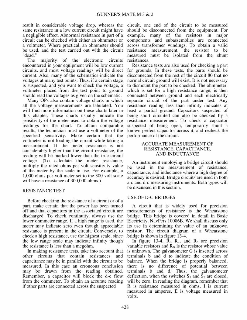
A circuit that is widely used for precision measurements of resistance is the Wheatstone bridge. This bridge is covered in detail in Basic Electricity, NavPers 10086B. We shall discuss only its use in determining the value of an unknown resistor. The circuit diagram of a Wheatstone bridge is shown in figure 13-4. In figure 13-4, Rl, R2, and R3 are precision variable resistors and RX is the resistor whose value is unknown. The galvanometer G is inserted across terminals b and d to indicate the condition of balance. When the bridge is properly balanced, there is no difference of potential between terminals b and d. Thus, the galvanometer deflection, when the switches S1 and S2 are closed, will be zero. In reading the diagram, remember that R is resistance measured in ohms, I is current measured in amperes, E is voltage measured in volts.
428
CHAPTER 13 - COMMON TEST EQUIPMENT AND LOGICAL TROUBLESHOOTING
The operation of the bridge is explained in a few logical steps. When the switch S2 is closed, current will flow from the negative terminal of the battery to point a. Here the current will divide as in any parallel circuit, a part of it passing through R1 and R2 and the remainder passing through RS and RX. The two currents, labeled I1 and I2, unite at point c and return to the positive terminal of the battery. The value of I2 depends on the sum of resistances R1 and R2 , while the value of I2 depends on the sum of resistances R3 and RX. R1, R2 and R3 are adjusted so there will be no deflection of the galvanometer needle when both switches are closed. Thus, there is no difference of potential between points b and d. This means that the voltage drop across R1 (E1.) is the same as the voltage drop across R3 (E3). By similar reasoning, the voltage drops across R2 and RX, that is E2 and EX, are also equal. Expressed algebraically, E1 = E3 or I1 Rl = I2 R3 and E2 = EX or I1 R1 = I2 RX Dividing the voltage drop across R1 and R3 by the respective voltage drop across R2 and RX, I1 R1 I2 R3
-------- = ---------- I1 R2 I2 RX
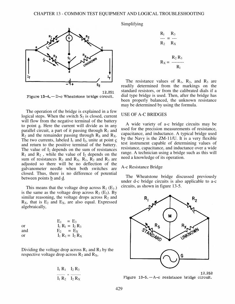
Simplifying Rl R3 --- = --- R2 RX R2 R3 RX = -------- Rl The resistance values of R1, R2, and R3 are readily determined from the markings on the standard resistors, or from the calibrated dials if a dial type bridge is used. Then, after the bridge has been properly balanced, the unknown resistance may be determined by using the formula. USE OF A-C BRIDGES A wide variety of a-c bridge circuits may be used for the precision measurements of resistance, capacitance, and inductance. A typical bridge used by the Navy is the ZM-11/U. It is a very flexible test instrument capable of determining values of resistance, capacitance, and inductance over a wide range. A technician using a bridge such as this will need a knowledge of its operation. A-c Resistance Bridge The Wheatstone bridge discussed previously under d-c bridge circuits is also applicable to a-c circuits, as shown in figure 13-5.
429
GUNNER'S MATE M 3 & 2
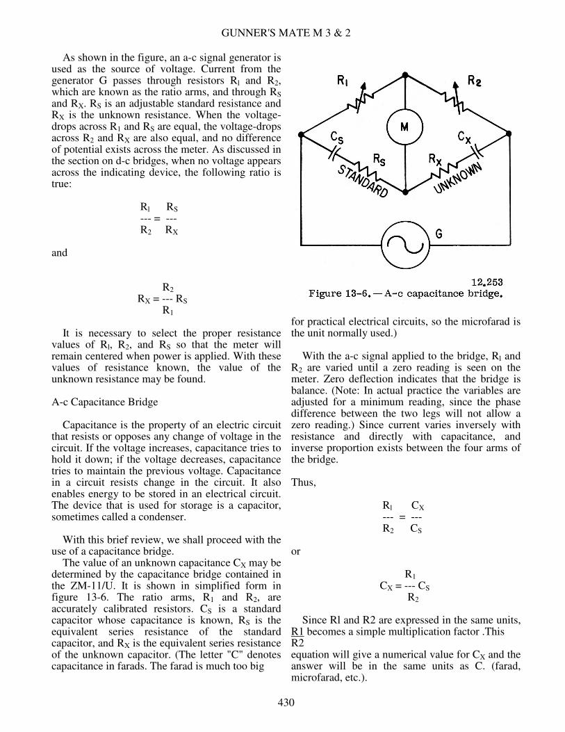
As shown in the figure, an a-c signal generator is used as the source of voltage. Current from the generator G passes through resistors Rl and R2, which are known as the ratio arms, and through RS and RX. RS is an adjustable standard resistance and RX is the unknown resistance. When the voltage-drops across R1 and RS are equal, the voltage-drops across R2 and RX are also equal, and no difference of potential exists across the meter. As discussed in the section on d-c bridges, when no voltage appears across the indicating device, the following ratio is true: Rl RS --- = --- R2 RX and R2 RX = --- RS R1 It is necessary to select the proper resistance values of Rl, R2, and RS so that the meter will remain centered when power is applied. With these values of resistance known, the value of the unknown resistance may be found. A-c Capacitance Bridge Capacitance is the property of an electric circuit that resists or opposes any change of voltage in the circuit. If the voltage increases, capacitance tries to hold it down; if the voltage decreases, capacitance tries to maintain the previous voltage. Capacitance in a circuit resists change in the circuit. It also enables energy to be stored in an electrical circuit. The device that is used for storage is a capacitor, sometimes called a condenser. With this brief review, we shall proceed with the use of a capacitance bridge. The value of an unknown capacitance CX may be determined by the capacitance bridge contained in the ZM-11/U. It is shown in simplified form in figure 13-6. The ratio arms, R1 and R2, are accurately calibrated resistors. CS is a standard capacitor whose capacitance is known, RS is the equivalent series resistance of the standard capacitor, and RX is the equivalent series resistance of the unknown capacitor. (The letter "C" denotes capacitance in farads. The farad is much too big
for practical electrical circuits, so the microfarad is the unit normally used.) With the a-c signal applied to the bridge, Rl and R2 are varied until a zero reading is seen on the meter. Zero deflection indicates that the bridge is balance. (Note: In actual practice the variables are adjusted for a minimum reading, since the phase difference between the two legs will not allow a zero reading.) Since current varies inversely with resistance and directly with capacitance, and inverse proportion exists between the four arms of the bridge. Thus, Rl CX --- = --- R2 CS or R1 CX = --- CS R2 Since Rl and R2 are expressed in the same units, R1 becomes a simple multiplication factor .This R2 equation will give a numerical value for CX and the answer will be in the same units as C. (farad, microfarad, etc.).
430
CHAPTER 13 - COMMON TEST EQUIPMENT AND LOGICAL TROUBLESHOOTING
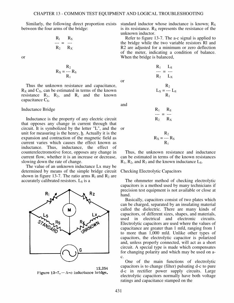
Similarly, the following direct proportion exists between the four arms of the bridge: Rl RS --- = --- R2 RX or R2 RX = --- RS R1 Thus the unknown resistance and capacitance, RX and CX, can be estimated in terms of the known resistance R1, R2, and Rs and the known capacitance CS. Inductance Bridge Inductance is the property of any electric circuit that opposes any change in current through that circuit. It is symbolized by the letter "L", and the unit for measuring is the henry, h. Actually it is the expansion and contraction of the magnetic field as current varies which causes the effect known as inductance. Thus, inductance, the effect of counterelectromotive force, opposes any change in current flow, whether it is an increase or decrease, slowing down the rate of change. The value of an unknown inductance Lx may be determined by means of the simple bridge circuit shown in figure 13-7. The ratio arms Rl and R2 are accurately calibrated resistors. LS is a
standard inductor whose inductance is known; RS is its resistance. RX represents the resistance of the unknown inductor. Refer to figure 13-7. The a-c signal is applied to the bridge while the two variable resistors Rl and R2 are adjusted for a minimum or zero deflection of the meter, indicating a condition of balance. When the bridge is balanced, R1 LS --- = --- R2 LX or R2 LX = --- LS R1 and R1 RS --- = --- R2 RX or R2 RX = --- RS R1 Thus, the unknown resistance and inductance can be estimated in terms of the known resistances R1, R2, and R3 and the known inductance LS. Checking Electrolytic Capacitors The ohmmeter method of checking electrolytic capacitors is a method used by many technicians if precision test equipment is not available or close at hand. Basically, capacitors consist of two plates which can be charged, separated by an insulating material called the dielectric. There are many kinds of capacitors, of different sizes, shapes, and materials, used in electrical and electronic circuits. Electrolytic capacitors are used where the values of capacitance are greater than 1 mfd, ranging from 1 to more than 1,000 mfd. Unlike other types of capacitors, the electrolytic capacitor is polarized and, unless properly connected, will act as a short circuit. A special type is made which compensates for changing polarity and which may be used on a-c. One of the main functions of electrolytic capacitors is to change (filter) pulsating d-c to pure d-c in rectifier power supply circuits. Large electrolytic capacitors normally have both voltage ratings and capacitance stamped on the
431
GUNNER'S MATE M 3 & 2
side. Capacitors must always be discharged before measuring. To discharge the capacitor, connect a jumper to each lead of the capacitor. A resistance measurement is made on the discharged electrolytic capacitor, using the high resistance range of the ohmmeter. When the ohmmeter leads are first applied across the capacitor, the meter pointer rises quickly and then drops back to indicate a high resistance. The test leads are then reversed and reapplied. The meter pointer should rise again-even higher than before - and again drop to a high value of resistance. The deflections of the meter are caused when the capacitor is charged by the battery of the ohmmeter. When the leads are reversed. the voltage in the capacitor adds to the applied voltage, resulting in a greater deflection than at first. If the capacitor is open-circuited, no deflection will be noted. If the capacitor is short circuited, the ohmmeter indicates zero ohms. The resistance values registered in the normal electrolytic capacitor result from the fact that there is leakage present between the electrodes. Because the electrolytic capacitor is a polarized device, the resistance will be greater in one direction than the other. Should a capacitor indicate a short circuit, one end of it must be disconnected from the circuit and another resistance reading made to determine if the capacitor is actually at fault. Unless your ohmmeter has a very high resistance scale, you will not see a deflection of the meter when checking small capacitors. Even a scale of R x 10,000 is not sufficient for very small ones; the smaller the capacity, the less leakage across the plates, therefore more resistance. USE OF THE MEGGER A thorough discussion of the operating principles of the megger is found in Basic Electricity. NavPers 10086-B. Briefly, a megger is an instrument for measuring very high resistance (insulation resistance). It consists of a hand-driven d-c generator and a suitable indicating meter, together with the necessary resistors. The name MEGGER is derived from the fact that it measures resistance of many megohms. Its full name is megohmmeter. The need for such an instrument exists because ohmmeters will not accurately measure these high resistances. The low voltage in an ohmmeter is not sufficient to move enough current through high resistances. The generator within
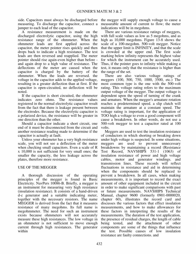
the megger will supply enough voltage to cause a measurable amount of current to flow; the meter indications will be in megohms. There are various resistance ratings of meggers, with full scale values as low as 5 megohms, and as high as 10,000 megohms. Figure 13-8 shows the scale of a 100-megohm. 500-volt megger. Notice that the upper limit is INFINITY, and that the scale is crowded at the upper end. The first scale marking below infinity represents the highest value for which the instrument can be accurately used. Thus, if the pointer goes to infinity while making a test, it means only that the resistance is higher than the range of the set. There are also various voltage ratings of meggers (100, 500, 750, 1000, 3500, etc.) The most common type is the one with the 500-volt rating. This voltage rating refers to the maximum output voltage of the megger. The output voltage is dependent upon the speed of turning of the crank and armature. When the megger's armature rotation reaches a predetermined speed. a slip clutch will maintain the armature at a constant speed. The voltage rating is important, for the application of TOO high a voltage to even a good component will cause a breakdown. In other words, do not use a 500-volt megger to test a capacitor rated at 100 volts. Meggers are used to test the insulation resistance of conductors in which shorting or breaking down under high voltage is suspected. In some situations, meggers are used to prevent unnecessary breakdowns by maintaining a record (Resistance Test Record, NAVSHIPS 531-1 (1063) of insulation resistance of power and high voltage cables, motor and generator windings. and transmission lines. These records will reflect fluctuations in resistance and aid in determining when the components should be replaced to prevent a breakdown. In all cases, when making measurements, it is important to record the exact amount of other equipment included in the circuit in order to make significant comparisons with past or future measurements. NAVSHIPS Technical Manual, chapter 9600 (formerly 0901-0000020, chapter 60), illustrates the record card and discusses the various factors that effect insulation measurements, and how to make allowances for these factors in interpreting the results of the measurements. The duration of the test application, the presence of residual charges, the length of cable being tested, and the attachment of other components are some of the things that influence the test. Possible causes of low insulation resistance are faulty connections. and
432
CHAPTER 13 - COMMON TEST EQUIPMENT AND LOGICAL TROUBLESHOOTING
accumulations of dirt or foreign material. Moisture is damaging to all insulation, varying with the type of insulation, and this will effect the megger test. A comparison of the results of successive test would reveal such progressive deterioration. Although the instruction in NAVSHIPS Technical Manual were written for ship's electricians, the conditions that affect insulation resistance on ship's power and lighting equipment have the same effect on missile launching systems, and will influence the megger readings in the same way. In the course of general maintenance and upkeep of a missile launching system, it is always possible that insulation resistance tests must be made. Therefore, GMMs should become familiar with the megger and how to use it. Precautions When Making Megger Tests. Precautions to be followed in the use of the megger are listed below: 1. When making a megger test, the equipment must NOT be live. It must be disconnected entirely from its source of Supply before it is tested. 2. Observe all rules for safety in preparing equipment for test and in testing, especially when testing installed high voltage apparatus. 3. Use well-insulated test leads, especially when using high range meggers. After the leads are connected to the instrument and before connecting them to the component to be tested, operate the megger and make sure there is no leak between the leads. The reading should be
infinity. To make certain the leads are not disconnected or broken, touch the test ends of the leads together while turning the crank slowly. The reading should be approximately zero. 4. When using high range meggers, take proper precautions against electric shock, especially while the component is under test. There is sufficient amount of capacitance in most electrical equipment to "store up" enough energy from the megger generator to give a very disagreeable and even dangerous shock. Owing to a high protective resistance in the megger, its open circuit voltage is not as dangerous, but care should be exercised. 5. Equipment having considerable capacitance should be discharged before and after making megger tests in order to avoid the danger of receiving a shock. This can be accomplished by grounding or short circuiting the terminals of the equipment under test. 6. Make sure that the connections on removable test leads on portable meters are secure. One report has been received of a test lead that came adrift, touched a rocket motor, and fired it. 7. Never implicitly trust insulation when considering personal safety. Insulation may look perfect yet not prevent a shock. Sufficient leakage current may be present to cause a fatal shock. Be sure power and control circuits are deenergized before beginning work on any part. Tag switches open so no one will close them while you are testing. NAVSHIPS Form 3960 (3-63) may be used for tagging switches open. You just need to write in your name and rate before attaching the tag. You remove the tag (no one else may do it)
433

GUNNER'S MATE M 3 & 2
when you have completed your work on the circuit and are ready to reenergize it.
TUBE TESTING Although each electron tube purchased by the Navy has been thoroughly tested electrically and mechanically, it is possible, nevertheless, for tubes to be damaged in shipment, storage, or handling. Therefore, a tube should be tested before it is used the first time. Electron tubes do not last indefinitely. Coated cathodes lose their power to emit electrons because the coating flakes off. Likewise, impregnated emitters of filament type tubes become depleted with age. There are other factors that cause electron tubes to function improperly-for example, defective seals permit air to leak into the tube and "poison" the emitting surface, and vibration or excessive voltage may cause internal shorts or opens. Whenever electronic equipment operates subnormally, one of the first maintenance procedures is to check the tubes with a tube tester. This often results in finding weak tubes and replacing them prior to failure;. As a GMM you are responsible for operating tube testers. The practice of wholesale removal and test of electron tubes on a periodic basis is not to be done. This routine type of tube testing has been specified in some maintenance manuals but revised editions will delete this requirement. The revised procedure will call for tube testing only if the equipment containing the tube is not performing properly. Isolate the cause, identify the tube that appears to be at fault, and remove and test that one. If test shows the tube to be good, return it to its socket, and continue your search for the cause of the trouble. Do not interchange tubes if it can be avoided. If the test shows the tube to be at fault, put in a new tube of the same kind, testing it first. Sometimes a new tube will not work in a particular socket, and several new ones may have to be tried. TYPES OF TESTERS Two types of tube testers are in general use. One, the EMISSION-TYPE tester, indicates the relative value of a tube in terms of its ability to emit electrons from the cathode. The second and more accurate type is the MUTUAL-CONDUCTANCE (or transconductance) tube tester. This tube tester not only gives an indication of the electron emission, but also indicates the ability of the grid voltages to control the plate current.
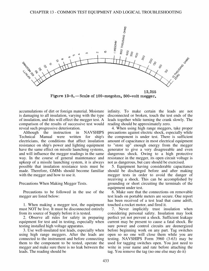
The end of the useful life of a tube usually is preceded by a reduction in electron emissivity that is, the cathode no longer supplies the number of electrons necessary for proper operation of the tube. In the emission tester, the proper voltages are applied to each electrode in the tube, and a meter indicates the plate current. If the tube has an open element or is at the end of its useful life, the emission tester gives an indication of this defect in the lower, or reject, portion of the meter scale. A tube may have normal emission and still not operate properly because tube efficiency depends on the ability of the grid voltage to control the plate current. The emission-type tester indicates only the plate current, and not the ability of the grid to control the plate current. The transconductance type tube tester, however, indicates how the tube operates, not merely the condition of the emitting surface. The terms "mutual conductance" and "transconductance" are used interchangeably in many texts. The Navy Department prefers transconductance but many commercial tube testers are marked "mutual conductance." When the prefix "dynamic" is used, as in "dynamic transconductance," it means that the characteristics of the tube in operation are being tested. The difference between the dynamic and static characteristics lies in the effect produced by the load impedance on the operation of the tube. Most tube testers, other than the emission type, test the dynamic characteristics by placing the tube in a working circuit. TYPICAL TUBE TESTER The tube tester shown in figure 13-9 is a typical portable tube tester of the dynamic mutual-transconductance type designed to test electron tubes of the standard type and many of the miniature and subminiature types. A multimeter section, using the same indicator, is also incorporated in the equipment to permit measurements of a-c and d-c volts, d-c mils, and resistance and capacitance in a number of ranges. This combination tube tester and multimeter is also called a vacuum tube analyzer. The equipment is capable of checking accurately all receiving tubes of filament or cathode type, and of 4-, 5-,6-, 7-prong, octal, loktal, naval, 7 pin miniature, subminiature, and acorn types. The tube tester has a roller chart (shown through "windows," lower part of fig. 13-9) indicating the tubes that may be tested. Listed opposite the tube designations is a series of
434
CHAPTER 13 - COMMON TEST EQUIPMENT AND LOGICAL TROUBLESHOOTING
numbers and letters which indicate the position of each switch and potentiometer of the SELECTORS and also the correct pushbutton to push. These switch positions connect the tube into a circuit that is comparable to the operating circuit of the tube. When the potentiometers are adjusted to the values indicated on the chart, the correct operating voltages are applied to the tube so that it can be checked under operating conditions. As newer tubes than those listed on the roller chart are used in equipments, other charts are published, giving the new switch positions and potentiometer settings. When conditions warrant, new roller charts incorporating the latest tubes are prepared. TESTS MADE WITH TUBE TESTER Let us now consider each of the individual tests performed by the instrument, one at a time. These tests are: (1) line voltage test, (2) short circuit test, (3) noise test, (4) rectifier test, (5) mutual-conductance test, (6) gas test, and (7) tests performed by means of the multimeter section.
Line Voltage Test It is necessary to maintain rated voltage across the primary of the power transformer if the meter of the tube tester is to register correctly. Therefore, a variable resistor is connected in series with the power input leads so that the voltage applied to the primary may be adjusted to the correct value. A special switch (the line-adjustment switch, lower left in fig. 13-9) connects the meter to the line, so that you can see when the line adjustment control is correctly set. The line voltage should be adjusted after the filament switch is in the correct position and the tube is in the test socket. Some tubes draw a high filament current, and would load down the operating voltage of the equipment if the line were adjusted first. The tube tester is designed to accurately test tubes under certain operating conditions, but the operating voltages must be accurate to accomplish this purpose. Correct line voltage adjustments will result in the required operating voltages.
435

GUNNER'S MATE M 3 & 2
Short Circuit Test The short circuit test is used to determine if there is a short between any two elements within the tube. The SHORTS switch connects the various elements of the tube under test to a voltage source in series with a neon lamp so that it glows if there is a short between the elements. On account of cross connections and taps in some tubes of recent design, the neon lamp will glow on certain positions of the test switch although the tube is in satisfactory operating condition. Study the tube data chart before discarding a tube. Intermittent shorts may be detected by tapping the tube with the finger while the switch is being turned. An instantaneous flash of the lamp as the switch is being turned should be ignored as this is caused by charging within the circuit. Noise Test The noise test is similar to the short circuit test and is used to check for any intermittent disturbances that are too brief to be detected on the neon lamp. Two test leads are connected into the jacks above and below the neon lamp (across the neon lamp) and the other ends of the leads are connected to the antenna and ground of a radio receiver. The SHORTS switch is then turned; through the various positions as the tube under test is tapped gently. Any intermittent disturbances between the electrodes cause a momentary oscillation that is reproduced by the loudspeaker! as noise. Rectifier Test Rectifier tubes and diode detector tubes can be tested only for emission; therefore, the rectifier test is quite simple. The diode or rectifier tubes are tested by first setting all the switches and potentiometers to the positions indicated on the roller chart. The tube is placed in the proper socket and the line voltage is adjusted after the tube has been allowed time to warm up. Then the designated diode or rectifier button is pushed. The meter will indicate above the rectifier mark for a good tube. If the reading is below the mark, the tube is weak or gassy. If there are two or more plates in the tube, each is tested separately. Mutual-Conductance or Quality Test Mutual-conductance tests are performed on amplifier tubes by positioning the SELECTOR
switches and potentiometers as indicated by the roller chart. After placing the tube in the proper socket, and adjusting the line voltage, a short circuit test should be conducted. To make the mutual-conductance test, the designated pushbutton is depressed. The meter will indicate the quality of the tube. It should be noted that to obtain accurate indications on the meter, the RANGE switch must be in the correct position. A reading lower than that given on the roller chart indicates a weak tube. A higher reading may indicate a gassy tube. Gas Test This test is used to determine whether there is gas present in the vacuumized envelope of the tube. It should be noted that this is NOT a test for gas-filled tubes such as thyratrons. The gas test usually is made after the quality test and, therefore, the switches and potentiometers are in the required positions. The GAS NO. 1 (P1) button is depressed which connects the proper grid and plate voltages. This will result in a certain indication on the meter. While GAS NO. 1 button is held down, GAS NO. 2 (P2) button is also depressed. If the tube is gassy, the meter reading will increase. If the increase is more than two divisions on the scale, the tube is not acceptable because of excessive gas. Multimeter Measurements The multimeter portion of the instrument is entirely separate from the tube tester although the same meters are sometimes used. The following measurements may be made: alternating current and direct current voltages up to 100 volts; resistance ranges (usually three ranges); d-c ranges, 0 to 20 and 0 to 200 milliamperes; capacitance, up to a maximum of 20 microfarads. TUBE TESTER LIMITATIONS In general, tube testers do not completely indicate tube performance because they present a fixed impedance to the tube grid and plate which mayor may not be that of the equipment in which the tube is to operate. Also, the tester takes no account of the interelectrode capacity of the tube. Specifications allow a wide deviation of interelectrode capacity which makes an accurate prediction of tube performance with a tube tester difficult. The range of operating frequency affects performance also.
436

CHAPTER 13 - COMMON TEST EQUIPMENT AND LOGICAL TROUBLESHOOTING
It is impracticable to design a complete testing instrument that will evaluate the performance of any tube in any circuit in which it is being used. A tube may test low on the tester and yet work perfectly well in the circuit or. on the other hand, it may check good in the tester and not function in the equipment. As a rule, therefore, only dead, shorted, or extremely weak tubes should be discarded purely on the basis of a tube tester check. Further, it is NOT advisable to replace a large number of tubes, especially in high frequency circuits, without checking their effect on the circuit, one tube at a time. In any complicated circuit, it is bad practice to arbitrarily replace a large number of tubes. It is better to replace them either tube by tube or in small groups. Be sure to replace each tube with an identical replacement. Another aid to checking new tubes is the "eyeball" check. Many new electron tubes with visible defects find their way into equipment. A quick visual inspection of all new tubes will save time by eliminating those with obvious defects. Some of the things to watch for are crushed spacers, loose internal plate structure, bent or missing pins, broken tips, and cracked glass envelopes.
CATHODE-RAY OSCILLOSCOPE The cathode-ray oscilloscope is one of the most useful and versatile of test instruments. It is essentially a device for displaying graphs of rapidly changing voltages or currents, but is also capable of giving information concerning frequency values, phase differences, and voltage amplitude. It is used to trace signals through electronic circuits, to localize source of distortion, and to isolate troubles to particular stages. The terms cathode-ray oscilloscope and cathode-ray oscillograph are sometimes used interchangeably but this is, strictly speaking, not correct. The oscillograph contains a means for producing records or tracings of the traces that flash across the screen of the cathode-ray tube. Because of the speed, pen and ink tracings such as those produced by an electrocardiograph are not possible; photographic records of the screen image are made. The tracings can be studied and compared to determine what the transient traces on the oscilloscope showed. Not all oscilloscopes have the recording device.
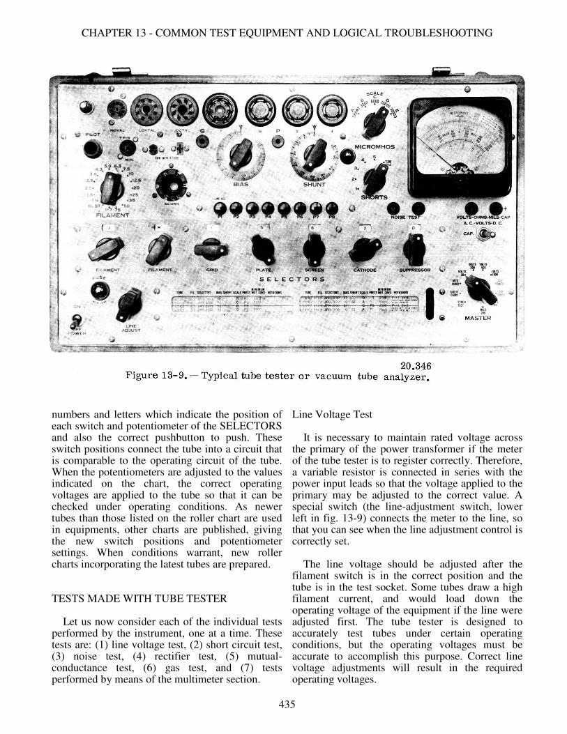
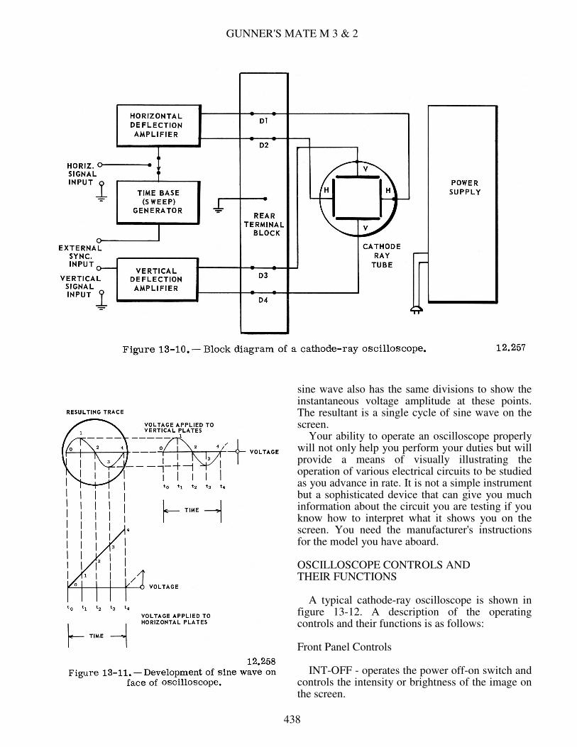
The oscilloscope is an instrument consisting of a cathode-ray tube and associated circuits for use in viewing wave shapes of voltages or currents. The cathode-ray tube, which is discussed in detail in Basic Electronics, NavPers 10087-B, consists of three parts- an electron gun for supplying a stream of electrons in the form of a beam, deflection plates for changing the direction of the electron beam a small amount, and a screen covered with a material which gives off light when struck by the stream of electrons directed at it by the gun. As shown in figure 13-10 the associated circuits include a time-base (sweep) generator whose output is amplified by the horizontal amplifier. This output is applied to the horizontal deflection plates (in the cathode-ray tube), causing the electron beam to move from the left to the right side of the screen at a uniform rate. Then the beam returns almost instantly to the left side, where it begins another sweep across the screen. This action is accomplished by generating a voltage that arises at a uniform rate to a certain value and then quickly drops to its starting value. A wave shape such as this is called a sawtooth wave. A sawtooth voltage wave is applied to the horizontal deflection plates, where it causes the electron stream to change direction. Since negative voltages repel and positive voltages attract electrons, the gradual rise in voltages causes the left plate to become increasingly negative and the right plate increasingly positive and thereby causes the spot to move across the screen. The quick drop of the voltage to its starting value returns the spot from right to left in a very short time. This is called the flyback time. The sawtooth voltage is normally generated by the time-base generator, and applied to the horizontal deflection amplifier. But if you want to use an external signal for horizontal deflection, you apply it to the horizontal input terminals. The waveform fed to the horizontal deflection amplifier is increased in amplitude to that needed for a trace of the desired length, and applied to the horizontal deflection plates. Signals applied to the vertical input terminals are amplified by the vertical deflection amplifier and applied to the vertical deflection plates. By studying figure 13-11 you can see how a sine wave is reproduced on the screen when a sawtooth voltage is applied to the horizontal plates and a sine wave voltage is applied to the vertical plates. The sawtooth, which represents time, is divided into segments numbered t0 to t4. The input
437
GUNNER'S MATE M 3 & 2
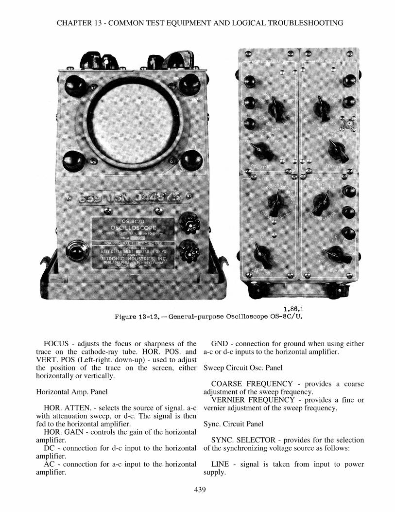
sine wave also has the same divisions to show the instantaneous voltage amplitude at these points. The resultant is a single cycle of sine wave on the screen. Your ability to operate an oscilloscope properly will not only help you perform your duties but will provide a means of visually illustrating the operation of various electrical circuits to be studied as you advance in rate. It is not a simple instrument but a sophisticated device that can give you much information about the circuit you are testing if you know how to interpret what it shows you on the screen. You need the manufacturer's instructions for the model you have aboard. OSCILLOSCOPE CONTROLS AND THEIR FUNCTIONS A typical cathode-ray oscilloscope is shown in figure 13-12. A description of the operating controls and their functions is as follows: Front Panel Controls INT-OFF - operates the power off-on switch and controls the intensity or brightness of the image on the screen.
438
CHAPTER 13 - COMMON TEST EQUIPMENT AND LOGICAL TROUBLESHOOTING
FOCUS - adjusts the focus or sharpness of the trace on the cathode-ray tube. HOR. POS. and VERT. POS (Left-right. down-up) - used to adjust the position of the trace on the screen, either horizontally or vertically. Horizontal Amp. Panel HOR. ATTEN. - selects the source of signal. a-c with attenuation sweep, or d-c. The signal is then fed to the horizontal amplifier. HOR. GAIN - controls the gain of the horizontal amplifier. DC - connection for d-c input to the horizontal amplifier. AC - connection for a-c input to the horizontal amplifier.
GND - connection for ground when using either a-c or d-c inputs to the horizontal amplifier. Sweep Circuit Osc. Panel COARSE FREQUENCY - provides a coarse adjustment of the sweep frequency. VERNIER FREQUENCY - provides a fine or vernier adjustment of the sweep frequency. Sync. Circuit Panel SYNC. SELECTOR - provides for the selection of the synchronizing voltage source as follows: LINE - signal is taken from input to power supply.
439

GUNNER'S MATE M 3 & 2
EXT. - signal is supplied by an external source connected to the EXT. terminal. INT. - signal is taken from the input to the vertical amplifier. LOCKING - selects the polarity and amplitude of synchronizing voltage applied to the sweep circuit oscillator. EXT. - input for external synchronizing voltage. Z AXIS - connection for external voltage to be used in intensity modulation of the electron beam. LINE - a source of the line supply frequency. Vertical Amp. Panel VERT. ATTEN. - provides for attenuation of a-c signals or d-c input without attenuation. VERT. GAIN - controls the gain of the vertical amplifier. DC - connection for d-c input to the vertical amplifier. AC - connection for a-c input to the vertical amplifier. GND - connection for ground when using either a-c or d-c inputs to the vertical amplifier. OPERATION The operation of the OS-8C/U cathode-ray oscilloscope for observation of waveforms is relatively easy, in that the signal to be observed is applied to the a-c terminal of the vertical amplifier and that the horizontal sweep frequency need only be synchronized with it. The steps for operating the OS-8C/U are listed below: 1. The signal to be observed is connected to the a-c input terminal of the vertical amplifier, and the ground connection of the input signal is connected to the GND terminal. 2. The INT-OFF control is turned clockwise to switch the power on. After the oscilloscope has warmed up, adjust the brightness or intensity of the trace to a comfortable level. 3. Set the COARSE FREQUENCY control to the lowest frequency. 4. Set the SYNC SELECTOR switch to the INT. position. 5. Set the VERT. GAIN and the VERT. ATTEN. controls for suitable deflection. 6. Set the HOR. GAIN control for desired pattern width. 7. Slowly rotate the VERNIER FREQUENCY control until the desired pattern appears and is steady.
8. If the number of cycles is too great, the COARSE FREQUENCY control is adjusted a step higher until the desired number of cycles appear and are steady. This may require readjustment of the VERNIER FREQUENCY control. 9. The trace can then be locked in synchronization by adjusting the LOCKING control, either positive or negative, until the pattern appears steady and fixed. When it is desired to use an external synchronizing voltage, it can be connected into the EXT. synchronization terminal. The SYNC. SELECTOR must be turned to EXT. The other controls are adjusted as above. When it is desired to use line voltage for synchronization, the SYNC. SELECTOR is turned to LINE and the other controls are adjusted as above. PRECAUTIONS WITH OSCILLOSCOPE The principal precaution to be observed in the use of cathode-ray tubes is not to permit the beam to remain for a long period of time on one portion of the cathode-ray tube screen as this may cause the tube to become burned or streaked. To prolong tube life, the intensity and focus controls should always be adjusted for minimum readable brilliance to produce the smallest practicable spot or narrowest line. Cathode-ray tubes should be handled with extreme care. If a cathode-ray tube is broken, the relative high external pressure will cause the tube to implode (burst inwardly), which will result in the inner metal parts and glass fragments being expelled violently outward. In addition to the danger from the flying fragments, the inner coatings of some tubes are poisonous if absorbed into the blood stream. Cuts from such coated glass can cause serious, even fatal, illness. Therefore, do not break defective tubes when preparing to dispose of them. Place the removed tube in the empty box of the replacement tube, and don't leave it around on work benches, etc. Safety glasses and gloves should be worn while handling CRT tubes. The case of the oscilloscope offers some protection to the tube, but do not handle it roughly. When stowed, it should be secured so it will not shift about.
SERVICING TRANSISTOR CIRCUITS After you have worked with vacuum tube equipment, you will find that maintaining and
440
CHAPTER 13 - COMMON TEST EQUIPMENT AND LOGICAL TROUBLESHOOTING
troubleshooting transistorized equipment presents no new problems. Most transistorized equipments use printed circuits, on which components are neatly arranged without stacking. This makes the transistors, resistors, capacitors, and other components easy to get at for troubleshooting. However, you must be careful to prevent damage to the printed wiring while you are investigating with test probes. One of the outstanding advantages of transistors is their reliability. Over 90% of the failures in electron tube equipment are tube failures. Transistors, however, have long life. This factor, among others, decreases the amount of maintenance necessary to keep transistorized equipment operating. Transistor Servicing Techniques The techniques used in servicing transistorized equipment are similar to those used in servicing electron tube circuits. Basically, these techniques are:
1. Power supply check 2. Visual inspection 3. Transistor check 4. Voltage check 5. Resistance check 6. Signal tracing 7. Component substitution
Power Supply Check The first step you should take in troubleshooting is to check the power supply to see if its output voltages are present, and are set at their correct value. Improper supply voltages can cause odd effects. You can prevent many headaches if you first check the power supply. Transistor circuits require relatively low amounts of power compared to electron tube circuits and, for this reason, small batteries like the carbon-zinc types and the newer mercury types are used. When transistor circuits are operated from an a-c source, the transistor power supply uses components smaller than those needed for electron-tube power supplies. Visual Inspection Visual inspection is a good servicing technique. Occasionally you can find a loose wire or faulty connection before extensive voltage checks are made. Faulty components such as
burned resistors seldom occur since the power supply voltage usually is very low compared to a vacuum tube power supply. Although transistors do not require a vacuum, they must be hermetically sealed, according to U.S. Joint Army-Navy (JAN) specifications in glass or metal cases. Plastic cannot be relied upon to remain moistureproof. Water vapor will quickly contaminate any unprotected transistor junction, and greatly increase the saturation current. Visually inspect transistors for broken seals. Transistor Check Transistors, like electron tubes, can be checked by substitution. Transistors, however, have a characteristic known as leakage current which may affect the results obtained when the substitution method is used. The leakage current can affect the gain or amplification factor of the transistor. It is more critical in certain applications than in others. Thus, it is possible that a particular transistor will operate satisfactorily in one circuit and not in another. It also has been found the amount of leakage current will increase slightly as the transistor ages. Transistor Checker. - Transistors can be checked by using a Transistor Tester. The following tests will reveal the condition of a transistor. 1. Tests to determine if its elements (emitter, base, collector) are short circuited. 2. A test to determine the current gain. The technical expression for this procedure is "measuring the beta parameter of a transistor." Basic Electronics, NP 10087-B points out that current gain is assigned the symbol BETA (β). One type of transistor tester used by technicians is the TS-1100/U. It can measure current gain while the transistor under test is either in or out of the circuit. But the transistor must be removed from the circuit when you are checking for a short-circuited condition. Voltage Checks Voltage measurements provide a means of checking circuit conditions in transistor circuits as they do in tube circuits. The voltages in transistor circuits are much lower than in tube circuits. For example, the bias voltage between the base and emitter is in the order of 0.05 to 0.2 volts. Therefore, a sensitive VTVM is usually required. When you make voltage
441
GUNNER'S MATE M 3 & 2
checks, make sure polarity is observed to avoid error in measurements. In an electron tube circuit, if you find a positive voltage on a grid, a leaky coupling capacitor is indicated. But in a transistor circuit the base-to-emitter voltage may be positive or negative, depending on the type of transistor. For example, the PNP type normally operates with the base negative with respect to the emitter, whereas the opposite is true of NPN transistors. (If you need to refresh your memory on the construction and theory of transistors, refer to Basic Electronics, NavPers 10087-B.) Check the schematic of the circuit under test for the proper polarity as well as magnitude of voltage. Current Check There may be times when you will want to make a current check in a circuit. In circuits that are wired in the conventional manner, you can easily unsolder a lead or remove a connection, and then place an ammeter in the circuit. With printed wiring this is not always possible. But you can calculate the current by using Ohm's law. For example, if the collector is to be measured, measure the voltage drop across the collector resistor (load) and measure the resistor with an ohmmeter. By using Ohm's law, you can calculate the collector current. Resistance Checks Resistance measurements generally are not made in transistor circuits, except to check for open windings in transformers and coils. Resistors and transistors have little tendency to burn up or change value, because of the low voltage power supplies used in transistor circuits. It is important to remember that, before you attempt to measure the resistance of any transistor circuit component, you must REMOVE THE TRANSISTOR OR COMPONENT. Since the ohmmeter has a battery, the wrong voltage polarity may be applied to a critical stage and cause permanent damage to the transistor. Another word of caution. Always disconnect the supply voltage before you remove a transistor from its socket. This prevents current surges that might damage the transistor. Signal Tracing and Component Substitution You can trace a signal through a transistor circuit just as you do in a vacuum tube circuit.
When you find a faulty component, replace it with a duplicate. Charts are supplied with the equipment, showing what transistors may be used. Precautions Although transistors are rugged, you must observe certain precautions. The leads are the most fragile part. Whether they are long and flexible or short and rigid, they should be treated carefully. When transistors with long flexible leads are soldered or resoldered, make sure you don't overheat the transistor. Use the heatsink technique. Heat from the soldering iron must be dissipated so it is not carried into the transistor via the leads. If the transistor is being wired into a circuit, each lead must be gripped between the iron and the transistor by a heat shunt (fig. 12-9) to reduce the heat transmission. The metal jaws act to form a low resistance heat path which conducts the heat away from the part. The soldering iron should be a small pencil type of low wattage (35-40 watts). When inserting (soldering) the transistor leads into a circuit, be careful of voltage polarity. Incorrect polarity can easily and permanently damage a transistor. Transistors with short rigid leads usually are plugged into sockets. In some cases, however, these transistors are plugged directly into the printed board, and then dip soldered. Transistors require low operating voltages. Small changes in these voltages can greatly upset the biasing of transistors. In some circuits, small bias changes can result in destruction of the transistor. Therefore, make sure you don't short out any circuit component. This action could disturb all the voltage relationships in the equipment, and thus destroy a number of transistors. Except for the special precautions and servicing techniques mentioned here, servicing transistor equipment should present no greater problem than servicing the electron tube counterparts.
TROUBLESHOOTING The materials used in launching system equipment are considered to be the best obtainable. The equipment has been carefully inspected and adjusted at the factory to reduce maintenance to a minimum. However, a certain amount of checking and servicing by you will always be necessary if your equipment is to be kept in efficient and dependable condition. A large part of your daily
442

CHAPTER 13 - COMMON TEST EQUIPMENT AND LOGICAL TROUBLESHOOTING
activities will be spent in preventing equipment failure by detecting defective operation and component deterioration in the early stages. This is accomplished by properly carrying out the prescribed preventive maintenance routine. Inefficient performance of preventive maintenance programs will accelerate the deterioration of your ship's armament, and will increase the time that you spend troubleshooting. Nevertheless, components do break down even under ideal conditions, and you will have to troubleshoot to find and correct the casualty or malfunction caused by faulty components. "Troubleshooting" is a term used to mean locating the cause of casualties to equipment. Another term often used is "casualty analysis." The name is not important but the task is. An inoperative power component can disable a whole system. It is vital to the operation of the missile system to locate the faulty component and replace or repair it. The most important part of troubleshooting is the logical approach. Without this approach, troubleshooting becomes a hit-or-miss affair that consumes much time and energy. In this section we will describe the troubleshooting procedure which is followed by most experienced technicians in locating all except the most self-evident faults. It consists in starting with large areas (circuits or parts of a circuit) suggested by the symptoms and eliminating those areas where the fault is NOT located. When the general area containing the fault is identified, progressively smaller segments are eliminated until only the small segment containing the fault is left. When this stage is reached, the fault usually reveals itself; if not. it can be located by individually testing a small number of parts and connections. Logical troubleshooting by a process of elimination can by applied to all types of ordnance equipment. In this section we will confine the discussion solely to electronic troubleshooting techniques. However, the basic concept of the troubleshooting philosophy described here applies equally well to mechanical, electrical, and hydraulic equipment. TROUBLESHOOTING PROCEDURE The following procedure is general enough to be useful when troubleshooting most electronic equipments. Figure 13-13 shows in block form the seven steps required to analyze the equipment, find the defective component, and make the appropriate repairs.
First, of course, you must recognize that some part is not functioning as it should. That means you must know how it should function so that you can recognize symptoms of malfunctioning. STEP 1. Investigate the symptoms. Try to locate the trouble by observing the equipment's operation. This may mean applying an input signal, some physical movement of the equipment's parts, or other means of activating operation. Check the operator's impressions of what happened at the time of failure. You should check all meters, lamp displays, or other monitoring devices. Too for any telltale evidence that will reveal the major unit in which the trouble exists. If you know the equipment well.
443
GUNNER'S MATE M 3 & 2
you can generally tell in what functional circuit the fault exists by observing the operation of the equipment and meter or lamp indications. This first step is the beginning of the process of casualty analysis using effect-to-cause reasoning. You see the effect (symptoms); now you must analyze the evidence to find the cause of trouble. STEP 2. An internal visual check is the logical second step in finding a defective component. Look for loose connections, burned parts, controls which are not working properly, resistors which are discolored, tubes without glowing filaments, or any other abnormal indications. Many casualties do not result in symptoms which can be detected directly by our senses, so it is necessary to resort to other means of detecting failures. The next steps require the use of test equipment. STEPS 3, 4, and 5. Troubleshooting steps 3, 4, and 5 consist of localizing the trouble to the faulty part. If the trouble has not resolved itself from a logical solution of the data available in steps 1 and 2, you must then utilize the troubleshooting aids listed below. They are discussed in more detail later in this section. In conjunction with the troubleshooting aids and logical reasoning, tracing a signal from its source through a circuit is the best technique for isolating the trouble to a section, stage, or part. The use of test equipment is required. It is used to measure or indicate the presence of a signal at the various check points. The signal can be traced from the source until it is lost at some checkpoint, or you can start at the output of the circuit and work backward until you find the defective stage. To find the defective part is a matter of checking a small number of elements. Look for the simplest defects first. STEP 6. This entails the replacement or repair of the defective part. You know that ALL replacements or repairs should duplicate the defective part. In an emergency two resistors or two capacitors properly connected may be used to duplicate the value of the defective part. However, such substitutes are always temporary. The permanent replacement should be made as soon as the correct parts are available. Remember, permanent replacements are always exact duplicates. STEP 7. Test the circuit and equipment operation. Readjust the circuit if necessary. After you make either temporary or permanent
repairs, always test the equipment. Use the operational tests given in the applicable OP or log or Planned Maintenance System cards, if available. They contain information telling you what adjustments are required and how to make them. SYSTEM TROUBLESHOOTING AIDS Basically, the purpose of corrective maintenance is to restore the system's operation to acceptable standards. To restore the system to its operational standard, the operation and standards must be known. If the missile loader, for example, is expected to load a missile every 37 seconds but it takes 2 minutes per missile, it is not operating up to standard and you must find where the fault lies. The OPs for the system contain detailed information on the operation of the system as well as the functions of the units of the system. The Planned Maintenance System tells you what tests and maintenance are to be performed. One-Function Schematic Diagrams These drawings show the internal and interconnecting circuitry between all parts of the weapon system. Each depicts in a single diagram all circuits involved in one particular function, (quantity or signal) of a system. This eliminates the need for using many separate diagrams for each of the equipments involved in the particular function. Circuit information is displayed by functional flow from left to right. The unit in which the signal originates is on the left of the drawing; the unit that ultimately receives the signal is to the right. All major equipments, terminal boards, patch panels, dials, plugs, and other electrical components are labeled. These one-function diagrams are not only an aid in troubleshooting but they provide a key to the understanding of the entire weapon system. The OPs containing one-function diagrams are unclassified, and therefore are readily available to missile system personnel. Figure 13-14 shows an example of a simplified one-function diagram. Data Functional Diagrams These diagrams show data transmission and functional circuits relevant to weapon system loops or modes of operations. Primary data flow is depicted as heavy lines. Each diagram emphasizes all alternate and test inputs and all points
444

CHAPTER 13 - COMMON TEST EQUIPMENT AND LOGICAL TROUBLESHOOTING
of data readout such as servodials, test points, and 'scope indications for a particular loop or mode. By tracing the primary data flow lines you can quickly determine which components are significant to fault isolation and functional understanding. Each missile weapon system has its own set of data functional diagrams. For example, OP 3472, volume 8, contains the data functional diagrams for DDG 2-24 Class Tartar Guided Missile Weapon System. Control Functional Diagrams These diagrams are provided only for the more complex control circuits. The diagrams show the time-related, ON-OFF stages of lamps, relays, switches, and other control devices for the various control circuits, with primary data flow depicted as heavy lines. Use of these diagrams will enable you to quickly determine the desired ON-OFF stage of the various control or control related devices. A comparison with
the actual circuit indications will isolate a fault to specific functional areas or to components in the control circuit. Fault Directories In the PMS (Planned Maintenance System), tests are keyed to the troubleshooting procedures. The fault directories are the primary means of determining the appropriate troubleshooting aids for an indication of a fault observed in the system tests. Each fault directory lists the various phases of the associated test in corresponding sequence, with the probable faults which may occur during each phase of the test. References to the most appropriate troubleshooting documents associated with each test indication are provided by the directory. In most cases, the referenced documents are functional diagrams and fault logic diagrams. The Indicator Directory is the primary means of determining the appropriate troubleshooting
445
GUNNER'S MATE M 3 & 2
documents for an indication of a fault observed on a specific indicator during random operation of the system. This directory provides an alphabetical listing of all indicators shown in the functional diagrams. The listing references the most appropriate diagrams associated with each indicator. Fault Logic Diagrams These diagrams will enable you to rapidly isolate faults encountered in system tests. Each diagram (fig. 13-15) begins with a statement describing the fault. The first block in the diagram contains a question about the fault that may be answered either "yes" or "no". If the answer is yes, you proceed to the next block via the solid line; if the answer is no, you would follow the broken line leaving the box, which tells you what to check. The second block (via the solid line) contains a yes or no question similar to the one in the first block. You again determine the proper answer to the question and proceed to the next block according to the answer obtained. This process is repeated until you are referred to a block containing a statement describing the action required to correct the fault. Figure 13-15 is a simple example of a fault logic diagram; others are more extensive. Indications that occur normally during the system tests and which can be helpful in fault analysis are presented in the diagrams as questions. Blocks that contain fault correction procedures reference functional diagrams, further troubleshooting procedures, or the fault-troubleshooting documentation reference table associated with each fault logic diagram. EQUIPMENT TROUBLESHOOTING AIDS When the defective or improperly adjusted component has been found, equipment or unit troubleshooting aids come into use to help you restore the component to its proper functioning state. These aids include: (1) servicing block diagrams, (2) schematic diagrams, (3) voltage distribution diagrams, (4) voltage and resistance charts, and (5) equipment troubleshooting pyramids. A brief description of each of these follows. The troubleshooting charts have long been the basis of maintenance work. You will find them in numerous publications about your equipment, or posted on or near your equipment.
Troubleshooting Charts Troubleshooting charts give a systematic procedure for locating malfunctions in an equipment. The chart lists easily observed or measured symptoms of improper equipment functioning, the probable cause, and the corrective action to be taken by the technician. In most cases, troubles cannot be pinpointed to a particular circuit element (tube, resistor, capacitor, etc.) by means of the chart. However, the fault can be localized to a particular circuit and the faulty element then localized by checking tubes, taking waveforms, and measuring voltage and resistance. Before using the charts, observe all external indications of trouble. Check for blown fuses, open interlocks and switches, and the proper setting of operating controls. You may recognize this time-tested aid under other names. Block Diagrams This troubleshooting aid should enable the technician to see, in a general way, the course of each circuit. From it you can perceive the relationship between circuits and components. Also, you can determine the general location of the test points for checking the condition of the equipment. The servicing block diagram should aid you in localizing the trouble to a small segment. It thus stands, in usage, in an intermediate position between the trouble chart and the schematic diagrams. Schematic Diagrams A schematic diagram shows how the parts of a circuit are connected for the operation of the equipment. It does not tell how the parts look or how they are constructed. Each component is illustrated by a symbol. A set of schematics enables the technician to trace the passage of energy throughout the entire equipment, and to test the operating condition of each part and connection. Voltage Distribution Diagrams These diagrams trace the distribution of the supply voltages throughout the equipment. The diagrams show all the relays, contacts, switches, and access points for that particular voltage distribution.
446
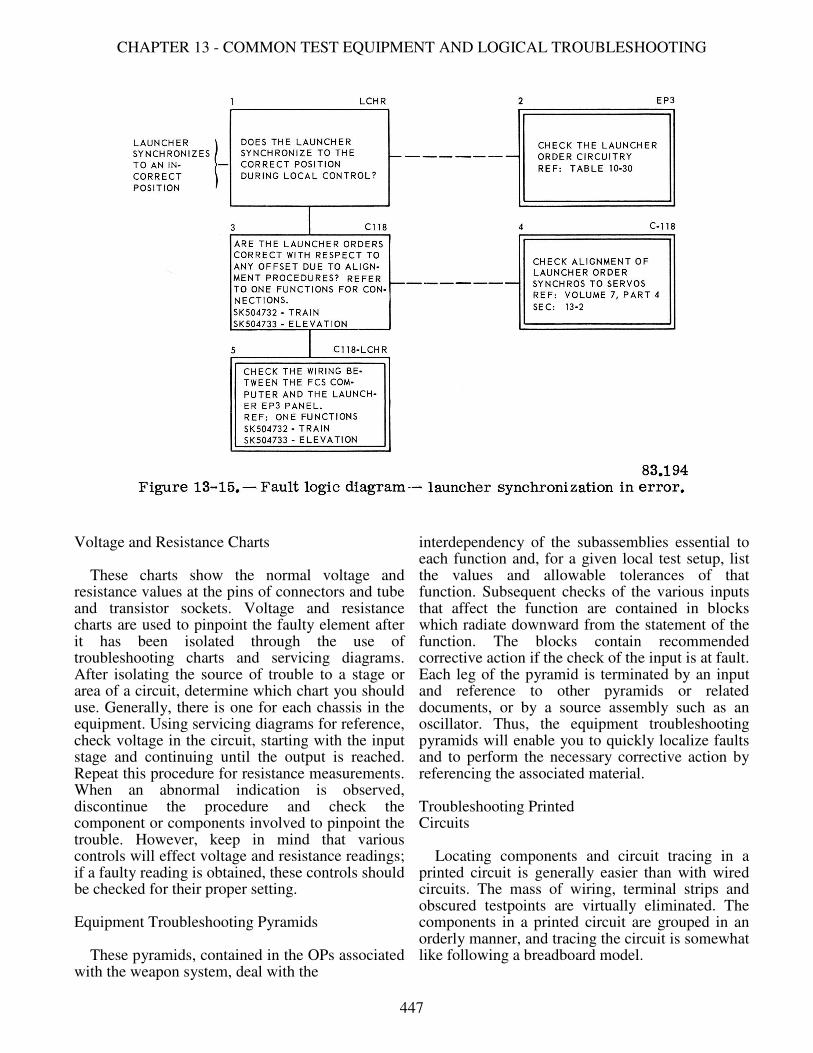
CHAPTER 13 - COMMON TEST EQUIPMENT AND LOGICAL TROUBLESHOOTING
Voltage and Resistance Charts These charts show the normal voltage and resistance values at the pins of connectors and tube and transistor sockets. Voltage and resistance charts are used to pinpoint the faulty element after it has been isolated through the use of troubleshooting charts and servicing diagrams. After isolating the source of trouble to a stage or area of a circuit, determine which chart you should use. Generally, there is one for each chassis in the equipment. Using servicing diagrams for reference, check voltage in the circuit, starting with the input stage and continuing until the output is reached. Repeat this procedure for resistance measurements. When an abnormal indication is observed, discontinue the procedure and check the component or components involved to pinpoint the trouble. However, keep in mind that various controls will effect voltage and resistance readings; if a faulty reading is obtained, these controls should be checked for their proper setting. Equipment Troubleshooting Pyramids These pyramids, contained in the OPs associated with the weapon system, deal with the
interdependency of the subassemblies essential to each function and, for a given local test setup, list the values and allowable tolerances of that function. Subsequent checks of the various inputs that affect the function are contained in blocks which radiate downward from the statement of the function. The blocks contain recommended corrective action if the check of the input is at fault. Each leg of the pyramid is terminated by an input and reference to other pyramids or related documents, or by a source assembly such as an oscillator. Thus, the equipment troubleshooting pyramids will enable you to quickly localize faults and to perform the necessary corrective action by referencing the associated material. Troubleshooting Printed Circuits Locating components and circuit tracing in a printed circuit is generally easier than with wired circuits. The mass of wiring, terminal strips and obscured testpoints are virtually eliminated. The components in a printed circuit are grouped in an orderly manner, and tracing the circuit is somewhat like following a breadboard model.
447
GUNNER'S MATE M 3 & 2
Chapters 4 and 5 in Blueprint Reading and Sketching, NavPers 10077-C, illustrate electrical and electronic diagrams, and give instructions for reading them.
PRECAUTIONS AND TECHNIQUES IN MAKING ELECTRICAL MEASUREMENTS
Some safety rules were given in the discussion of the use of each test instrument. Some additional precautions are given here for each type of measurement. VOLTAGE MEASUREMENT Most troubles can be found by taking voltage measurements. These measurements can be made easily since they are always made between two points in a circuit and the operation of the circuit need not be interrupted. Unless otherwise indicated in the voltage chart, voltages usually are measured between the indicated points and a common return. Always use a meter that has the same ohms-per-volt sensitivity as the one used originally to develop the voltage chart. The type of reference meter used will be stated on the chart, but your meter does not have to be an exact duplicate. It must have the same sensitivity rating, otherwise erroneous readings will result due to differences in circuit loading. Always begin voltage measurements by setting the voltmeter on the highest range, so that the voltmeter will not be overloaded. Then, if necessary to obtain increased accuracy, set the voltmeter to a lower range. Always use the range that gives maximum voltage reading. In checking cathode voltage, remember that a reading can be obtained when the cathode resistor is actually open, the resistance of the meter acting as a cathode resistor. Certain precautions must be followed when measuring voltages above a few hundred volts since high voltages are dangerous and can be fatal. When it is necessary to measure high voltages, observe the following rules. 1. Connect the common (ground) lead to the voltmeter. 2. Place one hand in your pocket. 3. If the voltage is more than 300 volts, shut off the power, connect the hot test lead, step away from the voltmeter, turn on the power, and note the reading on the voltmeter. Do not touch any part of the voltmeter, particularly
when it is necessary to measure the voltage between two points both of which are above ground. It is essential that the voltmeter resistance be at least 10 times as large as the resistance of the circuit across which the voltage is measured. If the voltmeter resistance is comparable to the circuit resistance, the voltmeter will indicate a lower voltage than the actual voltage present when the voltmeter is not in the circuit. When a voltmeter is loading a circuit, the effect can be noted by comparing the voltage reading on two successive ranges. If the voltage readings on the two ranges do not agree, voltmeter loading is excessive. The reading (not the deflection) on the highest range will be greater than on the lowest range. If the voltmeter is loading the circuit heavily, the deflection of the pointer will remain nearly the same when the voltmeter is shifted from one range to another. To minimize voltmeter loading in high resistance circuits, use the highest voltmeter range. Although only a small deflection will be obtained (possibly only 5 divisions on a 100 division scale), the accuracy of the voltage measurement will be increased. The decreased loading of the voltmeter will more than compensate for the inaccuracy which results from reading only a small deflection on the scale of the voltmeter. MEASUREMENT OF CURRENT Current measurements other than those indicated by the panel meters ordinarily are not required in troubleshooting. Under special circumstances, where the voltage and resistance measurements alone are not sufficient to localize the trouble, a current measurement can be made by opening the circuit and connecting an ammeter in series. This procedure is not recommended except in very difficult cases. CAUTION: A meter has least protection against damage when it is used to measure current. Always set the current range to the highest value. Then, if necessary, decrease the range to give a more accurate reading. Avoid working close to full-scale reading because this increases the danger of overload. In most cases, the current to be measured flows through a resistance which is either known or can be measured with an ohmmeter. The current flowing in the circuit can be determined by dividing the voltage drop across the resistor by its resistance value. The drop across the cathode resistor is a convenient method of determining the cathode current.
448
CHAPTER 13 - COMMON TEST EQUIPMENT AND LOGICAL TROUBLESHOOTING
When the meter is inserted in a circuit to measure current, it should always be inserted away from the r-f end of the resistor. For example, when measuring plate current, do not insert the meter next to the plate of the tube, but insert it next to the end of the resistor which connects to the power supply. This precaution is necessary to keep the meter from affecting the r-f voltages. MEASUREMENT OF RESISTANCE Before making resistance measurements, turn off the power. An ohmmeter is essentially a low range voltmeter and battery. If it is connected to a circuit to which power is being applied, the needle will be forced off scale and the voltmeter movement may be burned out. Capacitors must always be discharged before resistance measurements are made. This is very important when checking power supplies that are disconnected from their load. The discharge of the capacitor through the meter will burn out the meter movement and, in some cases, may endanger life. In a parallel circuit, the total resistance is less than the smallest resistance in the circuit. This is important to remember when troubleshooting with the aid of a schematic diagram. It is important to know when to use the low resistance range of an ohmmeter. When checking circuit continuity, the ohmmeter should be set on the lowest range. If a medium or high range is used, the pointer may indicate zero ohms, although the resistance may be as high as 500 ohms. When checking high resistance or measuring the leakage resistance of capacitors or cables, the highest range should be used. If a low range is used in this case, the pointer will indicate infinite ohms, although the actual resistance may be less than a megohm. When you measure resistance and find it less than you expected, make a careful study of the schematic to be certain that there are no parallel resistances. Before replacing a resistor because its resistance measures too low, disconnect one terminal from the circuit and measure its resistance again to make sure that the low reading does not occur because some part of the circuit is in parallel with the resistor. In some cases it will not be possible to check a resistor because it has a low resistance transformer winding connected across it. If the resistor must be checked, disconnect one terminal from the circuit before measuring its resistance.
When checking a grid resistance, a false reading may be obtained if the tube is still warm and the cathode is emitting electrons. Allow the tube to cool, or connect the ohmmeter test leads so that the negative lead is applied to the grid. Tolerance is the normal difference to be expected between the rated value of the resistor and its actual value. Most general purpose resistors have a tolerance of 20 percent. For example, the grid resistor of a stage might have a rated value of 1 megohm. If the resistor were measured and found to have a value between 0.8 megohm and 1.2 megohms, it would be considered normal. As a rule, the ordinary resistors used in circuits are not replaced unless their values are off more than 20 percent. Some precision resistors and potentiometers are used. When a resistor is used whose value must be very close to its rated value, the tolerance is stated on the diagram and in the maintenance parts list. Tolerance values for transformer windings are generally between 1 and 5 percent. As a rule, suspect a transformer which shows a resistance deviating by more than 5 percent from its rated value. Always allow the transformer to cool before the resistance test is made. Resistance in Electrolytic Capacitors The measurement of resistance in electrolytic capacitors with an ohmmeter was described earlier in this chapter. Note that the capacitor must be discharged before making measurements. Capacitors retain their charge for some time after being disconnected from the power supply. WHAT NOT TO TEST Certain missile components and equipment must not be tested at all on shipboard except by specially trained personnel or under special circumstances. Launcher firing circuits shall not be tested when rockets or missiles are on the launcher. Continuity tests of rocket initiating elements shall not be conducted aboard ship. Rocket motor igniter circuits shall not be tested aboard ship. No mechanical operations of any kind - machining, cutting, welding, drilling, etc. - on solid propellant rocket motors shall be permitted aboard ship. No disassembly is permitted on rocket motors without specific permission from the competent authority.
449
GUNNER'S MATE M 3 & 2
No steel instruments or tools which may cause sparks shall be used for cleaning or scraping explosive or flammable components of missiles, except as authorized by Naval Ordnance Systems Command. Under no circumstances shall attempts be made to disassemble or repair any fuze system aboard ship. Fuzes shall not be tested either mechanically or electrically aboard ship except as specifically authorized by NAVORD. Igniters shall not be disassembled or tested aboard ship unless specifically authorized and strictly in accordance with instructions from NAVORD. No electrical check shall be made of the cable connector of the S&A device unless specifically authorized by current directives.
SAFETY PRECAUTIONS The duties of the GMM require constant vigilance in the observance of safety precautions. These safety precautions include those concerning work with electrical and electronic equipment, work involving the handling of explosive ordnance material, work in the vicinity of equipment capable of starting fires or generating toxic gases, work done on high pressure hydraulic and pneumatic systems, and work done with small power tools. In addition to being thoroughly familiar with safety precautions, the GMM must know the authorized methods for treating burns and for giving artificial respiration to persons suffering from electric shock. Because of the many specialized devices you will use, and because of the potential hazards in your work, you should consider the formation of safe and intelligent work habits as being equal in importance to the development of technical knowledge and skills. You should always strive to exhibit the attitudes and practices which are characteristic of "safety mindedness." One of your objectives should be to become a safety specialist, trained in recognizing and correcting dangerous conditions and in avoiding unsafe actions. This section is in no way an exhaustive treatment of safety practices. Each GMM is expected to observe all of the safety precautions set forth in local directives, in equipment maintenance manuals, and in United States Navy Ordnance Safety Precautions, OP 3347. NAVSO P-2455, Department of the Navy Safety Precautions for Shore Activities, contains many safety precautions that are also applicable aboard ship. Safety rules for electrical and electronic equipment
aboard ship are collected in chapter 9670 (formerly ch. 67) in NAVSHIPS 0901-963-0000 (formerly) vol. III of BUSHIPS Technical Manual 250-000). Also every equipment OP contains a section on safety precautions. It is up to you to familiarize yourself thoroughly with all publications concerning safety. Many of the safety regulations have developed as a result of actual experience, so give them every possible consideration. CAUSES OF ACCIDENTS The precautions set forth in OP 3347 apply generally to operation of ordnance equipment and to the handling of explosives. However, the Navy does not expect blind adherence to them during extraordinary occasions; it is equally important that each individual use his own ability and initiative to prevent accidents during unforeseen conditions. For this reason it will be well for you to review a few of the basic causes of accidents. There are four closely related causes of accidents: CARELESSNESS, INEXPERIENCE, OVERCONFIDENCE, and FATIGUE. CARELESSNESS is something most human beings have to overcome. You have to cultivate good working habits-you must learn to coordinate your mental and physical actions to a point where you can concentrate on the important parts of the job at hand without having to worry about the minor mechanical functions pertaining to it. INEXPERIENCE can be the cause of accidents regardless of how careful the individual intends to be. The best solution to this problem is NEVER GUESS- you must learn to ask questions about things you are unfamiliar with or are not completely sure about. Beginners have a tendency to be overeager, and desire to put their hands to work. Eagerness is a good trait in any person, but you must realize that men with more experience usually know best. Work into a job gradually, and be particular about thoroughness; always be conscious of correct procedures in doing things. Train your mind and hands to function correctly so as to protect yourself and others from physical injury. For example, when you work with a screwdriver, be sure that your left hand (or right hand, if you are left-handed) is clear of the screwdriver bit, otherwise a slip of the screwdriver may drive the bit completely through your hand or may gouge deep into your arm. If you practice correct methods from the start, they'll become automatic before you realize it.
450

CHAPTER 13 - COMMON TEST EQUIPMENT AND LOGICAL TROUBLESHOOTING
OVERCONFIDENCE can come to both young and old, experienced and inexperienced. It is usually more closely associated with inexperience. Often, however, men grow overconfident when they become thoroughly familiar with a particular job, and have a tendency toward carelessness. To put it briefly, be confident that you know a job; but beware of overconfidence, because it may invite mistakes which can cause accidents. FATIGUE is the cause of a large percentage of accidents. You might be highly efficient when you have energy to burn, but it's another story when you get tired; your physical actions slow up and become inaccurate. Always prepare yourself for the task ahead by learning how much endurance it requires, and then get the necessary sleep, recreation, food, and exercise to keep on your toes. Remember, to be alert and to feel your best is extremely important on the job, and you can only enjoy this feeling by keeping yourself in good physical condition. In addition to studying safety precautions contained in OP 3347, and in this chapter, you are also referred to Ordnance Safety Precautions, OP 1014. The case studies and precautions set forth in this publication not only provide interesting reading, but also may save your life! The case histories (with pictures) of accidents in the Navy show the need for some of the safety rules you may consider unnecessary. OPERATING ORDNANCE EQUIPMENT Let us repeat-you should acquaint yourself thoroughly with the safety regulations provided in the appropriate OP and with those regulations posted aboard ship, before operating equipment. You will be taught how to apply many of these precautions while you are learning to operate ordnance equipment. The following list of general precautions will assist you. 1. Always inspect all training and elevating areas to make certain that all persons are clear, and that the areas are free of obstructions before operating directors, turrets, guns, or missile launchers. 2. Always use warning bells where provided before training or elevating gun mounts, turrets, or launchers during routine work and practices (except during GQ). . Before leaving directors, turrets, guns, or launchers, always train and elevate them to their securing positions: place all controls in the inoperative position, and deenergize all power supplied to them.
4. Whenever possible, have the regular operators posted at their stations before operating a director, turret, gun or launcher from a dummy director. 5. Slew directors, guns, and launchers only when it is necessary during practices. Be sure no one is in the path of the moving machinery. 6. All telephone stations should be manned when operating systems automatically or remotely. 7. Notify all operators and persons concerned before shifting a system from one mode of control to another. 8. Never operate directors, turrets, launchers, or guns in automatic without having the regular operators posted at their stations. 9. Do not hesitate to stop any person from operating ordnance equipment if he may cause a casualty to himself, the equipment, or to any other person. SAFETY PRECAUTIONS FOR MISSILE ELECTRICAL AND ELECTRONIC WORK Most of the safety rules for electrical work also apply to the operation, repair, and maintenance of missile electronic equipment. Furthermore, special precautions must be taken against the high voltages normally present in electronic devices, against dangerous effects of radiated energy, and against possible injury when handling electronic parts. The standard safety measures to be taken by personnel engaged in work on electronic equipment include the following: 1. Do not work on electronic apparatus with wet hands or while wearing wet clothing or any clothing which is loose and flapping. 2. When working within 4 feet of electronic equipment, do not wear clothing with exposed zippers, metal buttons or any type of metal fastener. No flammable articles such as celluloid cap visors should be worn. 3. Personnel should remove rings, wristwatches, bracelets, and similar metal articles when working on or within 4 feet of electronic equipment having exposed current-carrying parts. 4. When working on or near electronic apparatus, personnel shall wear high-cut shoes with sewed soles or safety shoes with nonconducting soles, if these are available. The use of thin soled shoes and those with metal plates or hobnails is prohibited. 5. Danger signs and suitable guards should be provided to warn all personnel wherever live
451
GUNNER'S MATE M 3 & 2
parts of electric circuits and equipment are exposed when the voltages involved are 50 volts or greater. 6. Insulated floor covering should be used in work areas where electronic equipment is serviced, particularly where the deck or walls are of metal. 7. Interlocks, overload relays, fuses, and other protective devices should never be altered or disconnected except during replacement; nor should any safety circuit be modified without specific authorization. 8. Metal enclosures for electrical and electronic equipment must be kept effectively grounded. 9. Adjustments, repair, and maintenance of missile radars, radio units, and test equipment must be done only by duly authorized personnel. 10. Adjustment of transmitters and other high voltage equipment should not be attempted while the motor-generator is running or while the rectifiers are energized, unless the adjustments can be made by the use of exterior controls provided for the purpose. 11. Except in emergencies, or when authorized by the proper authority, repairs should not be made on energized electronic equipment. If such work is necessary, it should be undertaken only by experienced personnel. 12. NEVER WORK ALONE near high voltage equipment. 13. Exercise caution when using tools with metal parts, metal tapes, cloth tapes with embedded metal threads, and cleaning equipment containing metal parts. None of these should be used in any area within 4 feet of electronic equipment or wiring having exposed current carrying parts. 14. When working around electronic circuits, keep your mind on your work. 15. Exercise as much care to avoid contact with low voltages as with high voltages. NEVER TAKE A SHOCK INTENTIONALLY FROM ANY SOURCE. This is a dangerous practice and is STRICTLY FORBIDDEN. If a particular circuit operates normally at 600 volts or less, and it is necessary to determine whether it is energized, use a voltmeter, voltage tester, or other suitable indicating instrument. DO NOT draw arcs with screwdrivers, etc. 16. Before you touch the terminals of apparently deenergized equipments, short them together and to ground, using a suitable insulated shorting device. 17. When nearby transmitting equipment is in operation, be on the alert to avoid shocks and
burns resulting from contact with antennas, antenna leads, and other exposed parts. 18. Special precautions concerning ordnance material should be observed before energizing transmitters. Electromagnetic radiations is a term used to describe energy radiated by radio and radar transmitting equipment. This energy is more commonly referred to as radio waves, radio frequency energy, or RF energy. RAD HAZ is an abbreviation for radiation hazards and is generally associated with the effects of radiation on humans. HERO is an abbreviation for hazards of electromagnetic radiation to ordnance. These terms are relatively new, although their effects have been known for some time. A thorough study has been made to establish the causes and the results of damage to the human body due to exposure of the body to radiation from various sources. The electromagnetic radiation from radar transmitters can ignite electric primers, flares, and similar sensitive ammunition components. In addition to ordnance items, the effects of radiation on combustible materials such as gasoline and other fuels is equally hazardous. Experiments with animals have revealed that high-intensity microwave radiation has destructive effects upon living organs. It has also been found that pain cannot always be relied upon to warn an individual of a dangerous radiation field. The most vulnerable parts of the body are those not effectively cooled by the blood stream. Damage to the body organs is believed to be entirely due to the heat generated as a result of the absorption of microwave energy by the body's tissues and not due to any mysterious property of the microwave radiation. Exposure of humans to microwave radiation of 10 centimeter (cm) wavelength region is considered to be the most dangerous, since the maximum heating occurs a few centimeters beneath the surface of the skin. The sensory nerves at the surface of the skin will not indicate the degree of internal heat produced and, unfortunately, the retina of the eye is situated at the zone of maximum heating. NAVORD OP 3565, Technical Manual, Radio Frequency Hazards to Ordnance, Personnel, and Fuel, tells more in detail the hazards of r-f radiation and the precautions necessary.
452
CHAPTER 13 - COMMON TEST EQUIPMENT AND LOGICAL TROUBLESHOOTING
HANDLING OF COMPONENTS Static electric charges carried on the human body can burn out crystal diodes which are often used in missile radar receivers. When installing a crystal, the cartridge should be held with the fingers touching one end only. The hand holding the unit should then be grounded against the missile airframe before the end of the crystal is brought into contact with the holder. Before you touch a capacitor, either connected in a deenergized circuit or disconnected entirely, you should short circuit the terminals to be sure that the capacitor is completely discharged. A suitable insulated lead or grounding bar should be used for this purpose. (Grounded shorting prods should be attached permanently to workbenches where electronic units are regularly serviced or overhauled.) There is no established case history of anyone having been killed by direct microwave radiated energy - yet. There is ample evidence that eye cataracts and various degrees of sterility have been caused by this radiation power. There is much evidence to further indicate the lethal capability of microwave radiation at power levels now readily available and in common usage. Aside from shock hazard there are two common types of radiation hazards associated with the use of high frequency, high-powered microwave equipment. One is the direct RF radiation from waveguides or antennas. The other is the X-radiation that can be generated in, and escape from, certain high voltage tubes. The swept area of tracking radars cannot be limited so personnel must keep out of the danger area and fuel and explosives must not be exposed in the danger area. The danger areas should be posted with warning signs. Never enter an area posted for microwave radiation until the transmitter is turned off and will remain off until further notice. Never look into an open waveguide or radar set connected to an energized transmitter. Care should be taken when using tools made of magnetic materials near radar magnetrons, since the tool can be pulled by the magnet into contact with dangerous high voltage circuits. Fuses should be removed and replaced only after the circuit has been completely deenergized. When a fuse "blows" it should be replaced only with a fuse of the same current rating. When possible, the circuit should be checked carefully before making the replacement, since the burned out fuse usually results from a circuit fault.
GENERAL SAFETY PRECAUTIONS Although many specific safety precautions are laid down for you in the three main publications that cover safety, there are a few general precautions which you should remember. Let's start by discussing the handling of handtools and power tools. Handling Tools and Machinery Many accidents occur because of the improper handling of tools. In general, these accidents occur in the form of physical injury to the person operating the tools. The following list gives the more -important general precautions to follow. 1. Whenever chipping, buffing, or grinding with handtools and powered tools, always wear goggles as a protection to the eyes. Little chips from a spinning grind wheel, or a bristle from a revolving wire brush can easily put out an eye. Many of these machines are provided with a guard; be sure to use it. 2. Always ground the provided ground lead located at the plug of portable tools such as electric drills to protect yourself from shock in case a ground occurs within the tool. 3. When working with sharp handtools, always work so that the tool is moved or thrust away from the body. 4. Never wear loose clothing or a neckerchief when working with rotating tools or machinery. Such clothing may become caught in the spinning parts and drag you bodily into the machine, causing severe physical injury. 5. Never use metal handtools on energized electrical equipment or circuits because you may get shocked, or the tool may cause a short circuit, causing molten copper to be blown into your face and eyes. 6. Never use handtools around running machinery, nor perform adjustments to running machinery unless absolutely necessary. 7. Never lay handtools on top of running machinery where vibration may cause the tool to fall into exposed working parts. 8. In the event your division officer deems it necessary to work on high voltage (exceeding 50 volts to ground) electric equipment while in an energized state, wear rubber gloves and use tools with insulated handles, and stand on an insulated mat. Always work with one hand in order to prevent the possibility of a circuit through your body from arm to arm.
453

GUNNER'S MATE M 3 & 2
9. When working with tools, always work in a physically comfortable position, and keep the weight of your body well centered. Electrical Work The following list is in addition to those precautions on handtools and machinery, and is applicable to all electrical work. This list will help you prevent electric shock or burns during daily work. 1. Whenever possible, operate electric switches and controls with one hand. 2. Do not block high voltage protective cutouts on doors or covers to keep the circuit energized with the cover off. It is intended that work be performed on such electrical equipment while the circuit is deenergized. 3. Always be sure that all condensers are fully discharged before commencing work on a deenergized high voltage circuit. Use an insulated shorting bar for this purpose. 4. Tag the switch OPEN (open the switch and place a tag on it stating "This circuit was ordered open for repairs and shall not be closed except by direct order of ______________.") at the switchboard supplying power to the circuit on which you wish to work. When possible, remove the fuses protecting the circuit and place them in your tool box for safekeeping until the job is complete.
5. Always remove fuses with fuse pliers, and never remove fuses until after opening the switch connecting the circuit to the source of supply. Never replace a fuse with one LARGER than the circuit is designed to take. 6. Utmost precaution should be observed when inspecting behind an open-back switchboard in an energized state. 7. Never use an incandescent test lamp unless its voltage rating is greater than the highest voltage which may be tested. 8. Always test a supposedly deenergized circuit with a voltage tester before commencing work on the circuit. 9. Never work on an electric circuit or network without first thoroughly acquainting yourself with its arrangement and with its points of power feed. Common Safety Features in Electronic Equipment You should be aware of the safety features that are generally included in electronic equipment. Some of the common safety features are interlock switches, bleeder resistors, current limiting resistors, insulating controls, and powerline safety devices such as fuses. Keep in mind that these features cannot always be counted on to function. Don't develop a false sense of security just because an equipment has safety features.
454