common-mode rejectors for pulse power diagnostics cable rout-ing is also far from ideal in some...
TRANSCRIPT

Naval Research LaboratoryWashington, DC 20375.5000
NRL Memorandum Report 6607
DTIt FILE COPY
Common-Mode Rejectors For Pulse Power Diagnostics
J. MATHEW
Beam Physics BranchPlasma Physics Division
0
NFebruary 15, 1990
DTICS ELECTE
FEB 16 19
Approved for public release; distribution unlimited.
| I II l|II/ I | e

SECURITY CLASSIFICATION OF THIS PAGE
Form ApprovedREPORT DOCUMENTATION PAGE OMB No 0704-0188
la. REPORT SECURITY CLASSIFICATION lb RESTRICTIVE MARKINGS
UNCLASSIFIED2a. SECURITY CLASSIFICATION AUTHORITY 3 DISTRIBUTION/AVAILABILITY OF REPORT
2b. DECLASSIFICATION/DOWNGRADING SCHEDULE Approved for public release; distributionunlimited.
4. PERFORMING ORGANIZATION REPORT NUMBER(S) S. MONITORING ORGANIZATION REPORT NUMBER(S)
6a. NAME OF PERFORMING ORGANIZATION 6b. OFFICE SYMBOL 7a. NAME OF MONITORING ORGANIZATION(If applicable)
NRL Memorandum Report 6607 Code 47956c. ADDRESS (City, State, and ZIP Code) 7b. ADDRESS(City, State, and ZIP Code)
Washington, DC 20375-50008a. NAME OF FUNDING/SPONSORING 8b. OFFICE SYMBOL 9 PROCUREMENT INSTRUMENT IDENTIFICATION NUMBER
ORGANIZATION (If applicable)
Office of Naval Research 47-1485-08c. ADDRESS (City, State, and ZIP Code) 10 SOURCE OF FUNDING NUMBERS
PROGRAM PROJECT TASK WORK UNITELEMENT NO NON00039871 NO 1 ACCESSION NO
Arlington, VA 22217-5000 61153N /¢RZ00209-4 RR01I0941
11. TITLE (Include Security Classification)
Common-Mode Rejectors for Pulse Power Diagnostics12. PERSONAL AUTHOR(S)
Mathew, Joseph13a. TYPE OF REPORT 13b. TIME COVERED 14. DATE OF REPORT (Year, Month, Day) 15 PAGE COUNT
Interim FROM TO 1990 February 15 3016. SUPPLEMENTARY NOTATION
17 COSATI CODES 18 SUBJECT TERMS (Continue on reverse if necessary and idenrafy by block number)
FIELD GROUP SUB-GROUP Common-mode rejectors DiagnosticsPulse power
19 ABSTRACT (Continue on reverse if hecessary and identify by block number)
Pulse power diagnostics are usually prone to common-mode noise pickup. A sure way of suppressingthis noise is to introduce a common-mode rejector in each suspected signal line. Two types of rejectors havebeen developed. One handles signals with risetimes exceeding 10 ns, or equivalently with frequencies lessthan 35 MHz. The other is suitable even for signals with subnanosecond risetime. Both have been optimizedto yield the highest rejection achievable. The method of winding employed and the interlead separation havebeen found to be quite important for proper operation of the common-mode rejector. Some of the underlyingmechanisms of ground noise generation are also briefly investigated.
20. DISTRIBUTION/AVAILABILITY OF ABSTRACT 21 ABSTRACT SECURITY CLASSIFICATION[M UNCLASSIFIED/UNLIMITED [C SAME AS RPT 0 OTIC USERS UNCLASSIFIED
22a. NAME OF RESPONSIBLE INDIVIDUAL 22b TELEPHONE (Include Area Code) 22c OFFICE SYMBOLJoseph Mathew (202) 767-3135 Code 4795
D Form 1473, JUN 86 Previous editions are obsolete. SECURITY CLASSIFICATION OF THIS PAGE
S/N 0102-LF-014-6603
I I I

CONTENTS
INTRODUCTION ....................................................................................... 1
I. INDUCED VOLTAGES ................................................................................ 1
II. GROUND CURRENT INTERACTIONS ........................................................... 3
M . REMEDIES ............................................................................................... 5
IV. HIGH FREQUENCY REJECTOR ................................................................... 6
V. ULTRA HIGH FREQUENCY REJECTOR ........................................................ 9
VI. CONCLUDING REMARKS ........................................................................... 11
ACKNOW LEDGEMENTS ............................................................................ 12
REFERENCES .......................................................................................... 12
DISTRIBUTION U ST ................................................................................. 19
Accesslon For
DTIC TAB 0Unm'meounoed 0Just Ilarttl@'o -
f- By ,. --.. .. .
I 15trllbt t,1 ,vlf
Disi

COMMON-MODE REJECTORS FOR PULSE POWER DIAGNOSTICS
INTRODUCTION
Pulse power machines typically generate pulses with voltages ranging from 100 kV to
10 MV at currents in the 1 kA to 10 MA range. Pulse durations are usually less than 1 As.
Ground noise can be severe in such environments. The large magnetic fields associated
with these machines can induce voltages on the order of 50 kV in ground loops formed
between signal cables and the machine ground return. For typical 100 foot long signal lines,
ground loop inductances are on the order of 10 AH. It is easy to see from V = Ldi/dt, that
ground currents exceed 1 kA, 200 ns into the pulse.
It is instructive to review some of the underlying mechanisms of ground noise genera-
tion in pulse power environments, in order to fully appreciate the need for common-mode
rejectors and their construction. Sporadic treatment of this subject may be found in much
of the available literature. Many, however, discuss ground currents in the context of low
power instrumentation techniques.'
I. INDUCED VOLTAGES
Induced voltages in ground loops can be avoided if sufficient care is taken in the design
of the pulse power machine and its associated diagnostics. Principles of electromagnetic
topology 2 can be successfully applied to develop designs immune to noise. A complete
Mumcrip approved December 26. 1989.
l li I I I I i i i1

shield is needed around the machine. The diagnostic room should be a shielded enclosure
and signal cable shields should be securely connected (no pigtails) at both ends to the
respective shield rooms. -If the conductivity of all shields is infinite, then the system
should be immune to noise.
Very often, however, conditions are not as ideal. It is usually inconvenient to locate
the machine in a shielded enclosure. Signal cables usually terminate on the outer shell of
the machine, which also serves as the return current carrying conductor. Large windows
in the shell distort the current flow pattern. Some magnetic flux leaks out, and voltages
could be induced in local loops formed by adjacent cables. Return currents can be very
large in the case of low impedance diodes, or arcs at the load. Resistive joints in the
return path usually cause mild arcing, and substantial ground noise is introduced in the
diagnostic cables.
Some pulse power components, for example Marx generators, striplines, etc. are
housed in an oil tank, with signal cables terminating at specific points on the pulse power
circuit, rather than at the tank wall. The cable shields are tied to the local circuit ground
if the diagnostic device is a voltage divider, a capacitive probe, or a current shunt. The
ground connection is sometimes improperly made using just a pigtail. The cable rout-
ing is also far from ideal in some cases. A substantial amount of ground noise is usually
introduced in these arrangements. The inductance of the Marx or stripline current re-
turn conductor can elevate the potential of local grounds with respect to the diagnostic
room ground. A single "contaminated" cable can cause ground currents to flow in other
"healthy" ones. In this respect the various interactions with all the trigger circuits and
cables should also be considered. There are also various stray capacitances between sensor
2

elements and high voltage surfaces, that can drive common-mode currents in some signal
cables.
Switches employed in pulse power machines generate inordinately large amounts of rf
noise. Cables with braided outer conductors invariably pickup both common-mode and
difference-mode rf noise. Heliax3 and Flexwell4 cables with solid corrugated copper outer
conductors are relatively immune to such pickup. Radio frequency waves also travel along
transmission lines formed by the signal cables and the nearby ground plane. A diagnostic
shield room is necessary to prevent these waves from interacting with oscilloscopes or
digitizers.
Finally, there are instances where a pulse power machine is used for beam generation
in charged particle accelerators. Time varying magnetic fields are sometimes employed for
inductive acceleration. Ground loops assume a great deal of importance in such instances.
II. GROUND CURRENT INTERACTIONS
Large ground currents, by themselves, need not necessarily introduce noise in mea-
sured signals. Common-mode currents flow exclusively in the outer shield. This is because
of the additional self inductance faced by common-mode currents in the center conduc-
tor(s). An important means of interaction with the difference-mode signal occurs via the
resistive voltage drop in the outer shield. The dc resistance of a 100-foot length of 1/2-inch
Heliax cable is 60 mfl. For 1 kA ground current, the resistive drop is 60 V. For times much
larger than the magnetic diffusion time of the outer shield (typically 10 t s), this voltage
drop directly adds to or subtracts from the difference-mode signal at the oscilloscope. The
noise is much larger than typical signal levels in this specific example. Times of interest are
3

usually much less than the shield diffusion time. For these short time scales, the resistive
drop is much larger due to skin effect. However, the voltage drop does not appear on the
inside surface of the shield until times on the order of the diffusion time. Hence there is no
noise introduced in the measured signals. Nonetheless, the voltage drops are large enough
that even a small fraction diffusing in (over time scales of 100 ns) can cause noticeable
errors in the signals. Braided cables are much more noisy in this respect. Any voltage
appearing on the inside shield surface causes additional capacitive currents to flow to the
inner conductor. A small fraction of the common-mode current also flows in the inner
conductor due to finite conductivity effects. This causes a voltage to appear across the
(50 fl) terminating resistor. For times on the order of the cable transit time, the inter-
action is complicated due to transmission line effects, but the net result is a lower signal
to noise ratio. Triaxial cables, configured properly, can eliminate these interactions. How-
ever, they do not provide complete immunity against other interactions described below.
Additionally, low loss high frequency cables are usually available only as coaxial lines.
Another interaction occurs at the sensor due to its proximity to ground currents
and high voltage surfaces. Ground currents can inductively couple to the sensor depend-
ing upon its geometric construction. Various electrostatic couplings can also introduce
difference-mode noise. This is especially so when the cable shield is not "tied" to the
machine, or when the connection is not sound. Once a common-mode to difference-mode
conversion occurs at the sensor, it is virtually impossible to separate the noise from the
signal.
Extremely good joints are called for at all cable connectors and splices. Loose con-
nections cause nonuniform current flows that greatly increase crosstalk with the inner
4

conductor. BNC connectors are not as rugged as Type N connectors in this respect. Large
ground currents can also cause mild arcing at resistive joints. This is especially important
at diagnostic room penetrations where the arcs can radiate rf directly into the shielded
enclosure.
II. REMEDIES
The most straightforward solution is to block the flow of ground currents, or at least
maintain them at modest levels. Fiber optic analog links completely eliminate ground
currents. They are, however, quite expensive for bandwidths exceeding 200 MHz, and
require frequent maintenance. Isolating pulse transformers are another possibility. But it
is virtually impossible to build one with adequate high frequency response and simultaneous
high voltage isolation capability. The capacitance between primary and secondary windings
provides a low impedance path for high frequency ground currents.
Another approach introduces a large common-mode inductor in the 110 V power line
to the diagnostic shield room. However, this approach does not get rid of ground currents
flowing in local loops formed by adjacent signal lines. Also, the diagnostic room coula be
elevated in potential with respect to ground, thus constituting an electrical safety hazard.
A sure way of controlling all ground currents is to employ a common-mode rejector
with each suspected signal line. This is accomplished by winding the signal cable over a
core of magnetic material. The rejector itself may be introduced at any convenient location
between the pulse power machine and the diagnostic room. The machine ground is thereby
isolated from the diagnostic room ground. The rejector may also be used to investigate
the presence of ground noise in a particular signal line. Described below are two common-
5

mode rejectors that are somewhat optimized to give the highest rejection achievable. The
first handles signals with risetimes exceeding 10 ns, or with frequencies less than 35 MHz.
The second is an ultra high frequency rejector for signals with risetimes in excess of 0.5 ns.
IV. HIGH FREQUENCY REJECTOR
A reasonably large inductance common-mode rejector can be built for signal risetimes
exceeding 10 ns. The rejector inductance should be much larger than typical ground loop
inductances, in order to justify its introduction. A large number of turns may be used on a
magnetic core if subminiature coaxial cable (say, RG-174/U) is used. One cannot, however,
arbitrarily increase the number of turns to yield large values of inductance. Multilayer
windings needed for this purpose have such large capacitances between layers that most
of the rejector inductance is shorted out at the frequencies of interest. The problem is so
severe that even the distance between the in-out leads becomes a determining factor. This
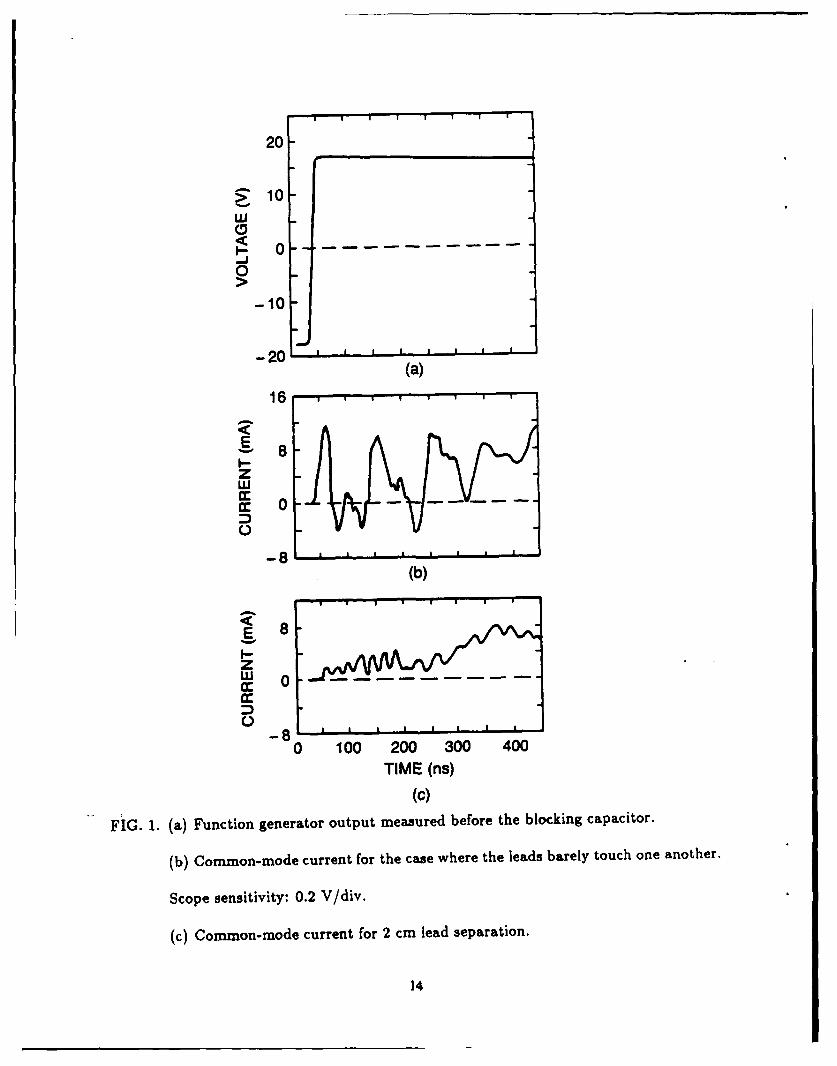
effect is illustrated by the traces in Fig. 1.
A Tektronix Model FG-504 Function Generator was employed to generate a pulse with
10 ns risetime. Insulated wire with outer dimensions approximating those of RG-174/U,
was used to build a ferrite cored inductor. Approximately 150 turns were wound in one
layer. The inductor was connected in series with another loop of wire with roughly 20 PH
inductance (to simulate the ground loop inductance of typical signal lines). The current
through this combination due to the input pulse was monitored by measuring the voltage
across a 50 fl series resistor. A 250 pF blocking capacitor was also introduced to prevent
core saturation due to the -18V quiescent dc outputt of the generator.
Fig. la shows the function generator output measured before the blocking capacitor.
6

The pulse amplitude is seen to be - 35 V, and the risetime - 10 ns. The current wavefcrm
appears in Fig. lb for the case where the in-out leads of the rejector barely touch one
another. Large oscillations are seen, presumably due to ringing between the parasitic
capacitance at the leads and the 20 AH loop inductance. One may estimate from the initial
12 mA current spike, a value for the parasitic capacitance of - 2 pF. This is a reasonable
value, in view of the fact that the dielectric constant for most ferrites is - 10 for the
frequencies of interest s. For the current trace in Fig. 1c, the winding was rearranged to
increase the lead separation to 2 cm. The estimated interlead capacitance for this case
is - 0.2 pF. The parasitic oscillations are greatly reduced, and the temporal behavior for
longer times is consistent with the proper operation of the rejector.
Based on the results of this experiment, a common-mode rejector was built using
RG-174/U. A simplified diagram of this rejector appears in Fig. 2. The minimum lead
separation was maintained at 2 cm. Type M 2 Ni-Zn ferrite6 was used for the core. Two
1.6 cm thick discs with inner diameter 6.4 cm and outer diameter 14.8 cm were taped
together to form the core. The resistivity of M 2 ferrite was - 1 x 10⁷ fl-cm and the initial
permeability was - 40 up to a frequency of - 50 MHz (Snoek limit7 ). The maxirum
number of turns that could be accommodated on the core was 97, giving an inductance
of - 2 mH. The winding was single layered except on the very inside of the core. The
interturn capacitance was therefore minimal. Over a 2 cm section midway between the two
ends, the winding was three-layered on the inside, but still single-layered on the outside as
shown in Fig. 2. The additional capacitance at this section would not increase the overall
capacitance noticeably, because it would be in series with other much smaller turn to turn
capacitances. Parasitic oscillations were observed to be negligibly small as in Fig. Ic.
7

A higher permeability ferrite (with a lower Snoek limit) could have been used. But
a high frequency ferrite was chosen to yield a rejector impedance that was predominantly
inductive throughout the frequency range of interest. The dielectric constant of ferrites
usually increases considerably to values in the 10 3 - 104 range as the frequency is lowered
to 1 1 kHz. Some ferrites with high permeability and low resistivity can have even higher
dielectric constants5 . Dimensional resonances assume importance in some of these cases
because the dimensions are comparable to the wavelength of electromagnetic propagation
in these media. Standing waves are set up, and rejector performance degrades appreciably.
The usefulness of a common-mode rejector depends to a large extent on the diagnostic
environment. Fig. 3 shows current traces obtained with and without the rejector described
above. The sensor was a Rogowski coil prone to common-mode pickup. The measured
signal is the current in a 10 m long trigger cable shorted at the far end. Eight such cables
were fed by a trigger generator delivering a maximum of 16 kA at 50 kV no load voltage.
The common-mode rejector was introduced between two lengths of Flexwell coaxial cable,
just a few feet from the generator. Considerable rf noise is expected at this location. Even
so, the rejector functions admirably well. The lower trace is displaced - 100 ns in .time
due to the additional transit time in the 17 m cable used for the winding.
The frequency response of the rejector to difference-mode signals is determined by
the length of cable used for the winding. The high frequency components of a signal are
preferentially attenuated in a coaxial cable primarily due to the frequency dependent skin
resistance of the inner and outer conductors. Fig. 4 shows the difference-mode response of
the rejector. The function generator was used again to output a 250 ns wide pulse through
a 0.1 uF blocking capacitor. A 50 fl Power Tee split the output pulse and transmitted two
8

half amplitude pulses in two 50 f] cables. One cable excited the common-mode rejector,
while the other went directly to a dual beam oscilloscope. Both pulses were subsequently
terminated in 50 fl and monitored on the scope.
The signal transmitted through the rejector is delayed approximately 100 ns as ex-
pected. The attenuation predicted for a 17 m length of RG-174 is - 3 db at 35 MHz
(corresponding to the 10 ns risetime of the input signal). This is roughly consistent with
the signal amplitudes in Fig. 4. Fast rising signals usually have limited pulse lengths. The
3 db attenuation figure is fully significant only for pulses with infinite duration. For short
duration pulses, the distortion is not as severe. If the transmitted pulse in Fig. 4 is scaled
in magnitude by -- 1.3, the resulting waveform would be quite similar to the generator
output waveform. It is also a simple matter to generate a computer code to correct the
data for the cable response, when the distortion is small as is the case here. Signals with
risetimes exceeding 10 ns can therefore be successfully handled by the rejector.
V. ULTRA HIGH FREQUENCY REJECTOR
The requirements are a lot more stringent for an ultra high frequency rejector. . The
cable response desired for ultra fast signals can only be achieved with a much shorter
lergth of RG-174. The capacitance shunting the rejector also needs to be greatly reduced.
Both requirements can be readily achieved by stringing a large number of ferrite beads on
a short length of cable. The surge impedance of the beads is what limits the common-mode
current at all frequencies above the Snoek limit.
Consider, for example, a rejector for risetimes exceeding 0.5 ns, or equivalently, for
frequencies less than 700 MHz. Approximately 100 ferrite beads are strung on a meter
9

length of RG-174. The bead dimensions are : 0.32 cm inner diameter, 0.64 cm outer
diameter, and 0.95 cm long. A frequent choice for the bead material is Type H Ni-Zn
ferrite6 , or equivalent. Typical catalog values for Type H ferrite are initial permeability
- 850, volume resistivity - 1 x 10⁵ fl-cm, saturation flux density - 3.4 kG, and Snoek
limit - 3 MHz.
Ferrite shield beads are usually used at frequencies much greater than the Snoek
limiting frequency, above which initial permeability decreases rapidly, and losses increase
proportionately. This behavior is usually attributed to the onset of ferromagnetic resonance
in the anisotropy field'. The empirical formula jsfr - 3 x 10o Hz for Ni-Zn ferrites7 , is
also explained by this phenomenon. pi. is the initial permeability, and fr is the limiting
frequency. Higher permeability ferrites have lower bandwidths according to this relation.
The insertion impedance of a ferrite bead is predominantly inductive below the Snoek
limiting frequency, but becomes resistive for all frequencies greatly exceeding the limit. For
common-mode rejection it hardly matters whether the impedance is inductive or resistive
as long as the current is limited. Catalog numbers for the 3 MHz bead referenced above
suggest an insertion impedance of - 40 fi at 25 MHz, 66 fi at 100 MHz, 57 fl al 700 MHz,
and 51 fl at 1 GHz. The impedance does not increase lineerly with frequency as would be
the case if the bead acted as an inductor. The total impedance for 100 beads is 5.7 kfl at
700 MHz. For a 50 kV ground induced voltage, the common-mode current is therefore
limited to a value less than 0.9 A. This represents a considerable reduction from the
kiloampere levels expected without the rejector, 100 ns into the pulse.
The inductance of a single bead below the Snoek limit is - 1.2 JLH. The rejector in-
ductance is therefore 120 14H, which is much greater than typical ground loop inductances.
10

It is, however, at least an order of magnitude smaller than typical values attained for the
high frequency rejector. Fortunately, large rejector inductances are normally not required
because pulse durations are usually small for machines requiring ultra fast diagnostics. In
the rare event that very high frequency common-mode noise is superimposed over low fre-
quency (kilohertz type) noise due to slow rising external magnetic fields, for example, the
signal can be capacitively coupled to "break the low frequency ground loop". Capacitors
need to be employed both in the signal line and in the ground (return) line. This is best
done at the sensor. If they are introduced at a different location along the signal trans-
mission path, they should be carefully constructed to minimize rf interference. Another
option is to employ sensors immune to low frequency common-mode noise.
The attenuation for difference-mode signals for a meter of RG-174 is 0.8 db at
700 MHz. As a result, for limited duration pulses, distortion levels are expected to be a few
percent. The common-mode rejector described has discrimination capabilities close to the
maximum achievable for ultra fast signals. Knowing the criteria for efficient common-mode
rejection, it is conceivable that a somewhat more optimized rejector can be built.
VI. CONCLUDING REMARKS
Pulse power diagnostics are frequently vulnerable to common-mode pickup. Signals
can be reliably measured in such environments if a common-mode rejector is employed with
each suspected signal line. Two different types of rejectors have been described. The high
frequency rejector is suitable for signals with risetimes exceeding 10 ns, or equivalently for
frequencies less than 35 MHz. The ultra high frequency rejector can be used for signals
with subnanosecond risetime. Both employ ferrite cores for fast response.
11

Control of common-mode currents addresses only part of the problem of noise pickup.
The other aspect deals with spurious difference-mode pickup at the sensor, which is outside
the scope of this paper. The classic example is the difference between a shielded and an
unshielded Rogowski coil when it is employed near high voltages. The large capacitive
currents flowing to the unshielded coil can easily induce spurious signals due to a variety
of higher order effects. A careful analysis of any diagnostic arrangement can usually
indicate the underlying mechanism of noise generation. J. C. Martin, one of the early
pioneers of pulse power technology, noted" "... there is no 'black magic' in pickup : the
laws of electromagnetism apply here just as anywhere else." In general, noise problems can
be averted if reasonable care is taken in the design of the sensor. Even better performance
is achieved if diagnostics are incorporated early on in the design phase of the machine.
ACKNOWLEDGEMENTS
This work was supported by the U. S. Office of Naval Research. C. A. Kapetanakos
and J. Golden of the Modified Betatron Section deserve special thanks for their support
and encouragement.
REFERENCES
1. R. Morrison, Grounding and Shielding Techniques in Instrumentation (Wiley, New
York, 1967).
2. W. Graf, "Practical Shielding and Grounding Techniques", Fast Electrical and Optical
Measurements, 1 (Martinus Nijhoff Publishers, Boston, 1986).
3. Andrew Corporation, Orland Park, Illinois.
4. Cablewave Systems, North Haven, Connecticut.
12

5. J. Smit and H. P. J. Wijn, Ferrites (Wiley, New York, 1959).
6. National Magnetics Group Inc., Newark, New Jersey.
7. J. K. Watson, Applications of Magnetism (Wiley, New York, 1980).
8. J. C. Martin, "Nanosecond Pulse Techniques", Pulsed Electrical Power Circuit and
Electromagnetic System Design Notes, Air Force Weapons Laboratory Report AFWL-
TR-73-166 (1973).
13
I I I I | I
20
10-wi
0_o
- 0-J
0
-10
-20 (a)(a)
16 , , ,
EI-zwcccc 0 -
-8(b)
zx 0
- I I I ' I I
0 100 200 300 400
TIME (ns)
(c)
FIG. 1. (a) Function generator output measured before the blocking capacitor.
(b) Common-mode current for the case where the leads barely touch one another.
Scope sensitivity: 0.2 V/div.
(c) Common-mode current for 2 cm lead separation.
14

w EIt 0
o E cC, 06 1.
wE
UJU
U.-U)
-9c
Cb E .) Z
0D 6
150

2
0-- IA 7I-2
z (a)
0-
-2I I I I I u I
0 100 200 300 400 500TIME (ns)
(b)
FIG. 3. (a) Signal trace obtained without the rejector. Scope sensitivity: I V/div.
(b) Signal measured with the rejector for the same experimental setup as in (a).
16

10 I II
0
'-40
0
0 100 200 300 400TIME (ns)
FIG. 4. Difference-mode response of the common-mode rejector showing the input pulse
from the signal generator, and the delayed pulse transmitted through the rejector.
The 6 V reference line is a guide for the eye.
17

DISTRIBUTION LIST(Revised December 18, 1989)
Dr. M. AllenStanford Linear Accelerator CenterStanford, CA 94305
Dr. W. BarlettaLawrence Livermore National LaboratoryP.O. Box 808Livermore, CA 94550
Dr. M. BartonBrookhaven National LaboratoryUpton, L.I., NY 11101
Dr. Jim BenfordPhysics International Co.2700 Merced St.San Leandro, CA 94577
Dr. Kenneth BergersonPlasma Theory Division - 5241Sandia National LaboratoriesAlbuquerque, NX 87115
Dr. Daniel BirxLawrence Livermore National LaboratoryP.O. Box 808Livermore, CA 94550
Dr. Charles BrauVanderbilt UniversityNashville, TN 37235
Dr. R. BriggsSSC Laboratory2550 Beckleymeade Ave.Suite 260Dallas, TX 75237
Dr. Allan BromborskyHarry Diamond Laboratory2800 Povder Mill RoadAdelphi, MD 20783
Dr. H. Lee BuchananDARPA1400 ilson Blvd.Arlington, VA 22209-2308
Dr. H. ButramSandia National LaboratoryAlbuquerque, NX 87115
19

Dr. H. CaponiTRW Advance Tech. Lab.I Space ParkRedondo Beach, CA 90278
Prof. F. ChenDepartment of Electrical EngineeringUniversity of California at Los AngelesLos Angeles, CA 90024
Dr. D. CherninScience Applications Intl. Corp.1710 Goodridge DriveMcLean, VA 22102
Prof. R. Davidson...Plasma Fusion CenterM.I.T.Cambridge, KA 02139
Dr. J. DavsonUniversity of California at Los AngelesDepartment of PhysicsLos Angeles, CA 90024
Dr. U.N. DestlerDepartment of Electrical EngineeringUniversity of MarylandCollege Park, MD 20742
Dr. H. DreicerDirector Plasma Physics DivisionLos Alamos Scientific LaboratoryLos Alamos, NM 87544
Prof. W.E. DrummondAustin Research Associates1901 Rutland DriveAustin, TX 78758
Dr. Don EccleshallBldg. 120-Room 241Ballistic Research Lab.Aberdeen Proving GroundsAberdeen, MD 21005
Dr. J.G. EdenDepartment of Electrical EngineeringUniversity of Illinois155 EBBUrbana, IL 61801
Dr. A. FaltensLavrence Berkeley LaboratoryBerkeley, CA 94720
20

Dr. T. FessendenLawrence Livermore National LaboratoryP.O. Box 808Livermore, CA 94550
Dr. A. FisherPhysics DepartmentUniversity of CaliforniaIrvine, CA 92664
Prof. H.H. FleischmannLaboratory for Plasma Studies and
School of Applied and Eng. PhysicsCornell UniversityIthaca, NY 14850
Dr. T. FowlerAssociate DirectorMagnetic Fusion EnergyLawrence Livermore National LaboratoryP.O. Box 808Livermore, CA 94550
Mr. George B. Frazier, ManagerPulsed Power Research & Engineering Dept.2700 Merced St.P.O. Box 1538San Leandro, CA 94577
LCDR U. FritchieSpace and Naval Warfare
Systems CommandAttention: Code PMV145BWashington, DC 20363-5100
Dr. S. GraybillHarry Diamond Laboratory2800 Powder Mill RoadAdelphi, MD 20783
Lt. Col. R. GullicksonSDIO-DEOPentagonWashington, DC 20301-7100
Dr. Z.G.T. GuiragosslianTRW Systems and Energy RI/1070Advanced Technology Lab1 Space ParkRedondo Beach, CA 90278
Prof. D. HammerLaboratory of Plasma PhysicsCornell UniversityIthaca, NY 14850
21

Dr. David HastiSandia National LaboratoryAlbuquerque, NM 87115
Dr. C.E. HollandsvorthBallistic Research LaboratoryDRDAB - BLBAberdeen Proving Ground, MD 21005
Dr. C.M. HuddlestonORI1375 Piccard DriveRockville, MD 20850
Dr. S. HumphriesUniversity of New MexicoAlbuquerque, NM 87131
Dr. Robert Hunter9555 Distribution Ave.Western Research Inc.San Diego, CA 92121
Dr. J. HymanHughes Research Laboratory3011 Malibu Canyon RoadMalibu, CA 90265
Prof. H. IshizukaDepartment of PhysicsUniversity of California at IrvineIrvine, CA 92664
Dr. D. KeefeLawrence Berkeley LaboratoryBuilding 50, Rm. 149One Cyclotron RoadBerkely, CA 94720
Dr. Donald KerstUniversity of WisconsinMadison, VI 53706
Dr. Edvard KnappLos Alamos Scientific LaboratoryLos Alamos, NM 87544
Dr. A. KolbMaxvell Laboratories8835 Balboa Ave.San Diego, CA 92123
22

Dr. Peter KornMaxwell Laboratories8835 Balboa Ave.San Diego, CA 92123
Dr. R. LinfordLos Alamos Scientific LaboratoryP.O. Box 1663Los Alamos, NM 87545
Dr. C.S. LiuDepartment of PhysicsUniversity of MarylandCollege Park, MD
Prof. R.V. Lovelace,School of Applied and Eng. PhysicsCornell UniversityIthaca, NY 14853
Dr. S.C. LuckhardtPlasma Fusion CenterM.I.T.Cambridge, MA 02139
Dr. J.E. MaenchenDivision 1241Sandia National Lab.Albuquerque, NM 87511
Prof. T. MarshallSchool of Engineering and Applied SciencePlasma LaboratoryS.W. Mudd Bldg.Columbia UniversityNev York, NY 10027
Dr. M. MazarakisSandia National LaboratoryAlbuquerque, NM 87115
Dr. D.A. McArthurSandia National LaboratoriesAlbuquerque, NM 87115
Prof. J.E. McCuneDept. of Aero. and AstronomyM.I.T.77 Massachusetts Ave.Cambridge, MA 02139
Prof. G.H. Miley, ChairmanNuclear Engineering Program214 Nuclear Engineering Lab.Urbana, IL 61801
23

Dr. Bruce MillerTITAN Systems9191 Town Centre Dr.Suite 500San Diego, CA 92122
Dr. A. MondelliScience Applications International Corp.1710 Goodridge DriveMcLean, VA 22102
Dr. Phillip MortonStanford Linear Accelerator CenterStanford, CA 94305
Dr. M. NahemowWestinghouse Electric Corporation1310 Beutah Rd.Pittsburg, PA 15235
Prof. J. NationLab. of Plasma StudiesCornell UniversityIthaca, NY 14850
Dr. V.K. NeilLawrence Livermore National LaboratoryP.O. Box 808Livermore, CA 94550
Dr. Gene NoltingNaval Surface Warfare CenterWhite Oak Laboratory10901 New Hampshire Ave.Silver Spring, MD 20903-5000
Dr. C.L. OlsonSandia LaboratoryAlbuquerque, NM 87115
Dr. Arthur PaulLawrence Livermore National LaboratoryP.O. Box 808Livermore, CA 94550
Dr. S. PennerNational Institute of Standards
and TechnologyWashington, D.C. 20234
Dr. Jack M. PetersonLawrence Berkeley LaboratoryBerkeley, CA 94720
24

Dr. R. PostLavrence Livermore National Lab.P.O. Box 808Livermore, CA 94550
Dr. Kenneth PrestvichSandia National LaboratoryAlbuquerque, NM 87115
Dr. S. PronoLavrence Livermore National Lab.P.O. Box 808Livermore, CA 94550
Dr. Sid PutnamPulse Science, Inc.600 McCormick StreetSan Leandro, CA 94577
Dr. Louis L. ReginatoLawrence Livermore National LabP.O. Box 808Livermore, CA 94550
Prof. N. ReiserDept. of Physics and AstronomyUniversity of MarylandCollege Park, MD 20742
Dr. M.E. RensinkLawrence Livermore National LabP.O. Box 808Livermore, CA 94550
Dr. D. RejLab for Plasma PhysicsCornell UniversityIthaca, NY 14853
Dr. J.A. RomeOak Ridge National LabOak Ridge, TN 37850
Prof. Norman RostokerDept. of PhysicsUniversity of CaliforniaIrvine, CA 92664
Prof. George SchmidtPhysics DepartmentStevens Institute of Tech.Hoboken, NJ 07030
25

Philip E. SerafimNortheastern UniversityBoston, MA 02115
Dr. Andrew SesslerLawrence-Berkeley National LabBerkeley, CA 94720
Dr. John SiambisLockheedPalo Alto Research Lab3257 Hanover StreetPalo Alto, CA 94304
Dr. Adrian C. SmithBallena Systems Corp.1150.Ballena Blvd.Suite 210Alameda, CA 94501
Lloyd SmithLawrence Berkeley National LaboratoryBerkeley, CA 94720
Dr. A. SternliebLawrence Berkely National LaboratoryBerkeley, CA 94720
Dr. D. StrawW.J. Schafer Assoc.2000 Randolph Road, S.E., Suite AAlbuquerque, NM 87106
Prof. C. StrifflerDept. of Electrical EngineeringUniversity of MarylandCollege Park, MD 20742
Prof. R. SudanLaboratory of Plasma StudiesCornell UniversityIthaca, NY 14850
Dr. W. TuckerSandia National LaboratoryAlbuquerque, NM 87115
Dr. H. UhmNaval Surface Warfare CenterWhite Oak Laboratory10901 Nev Hampshire Ave. Code R41Silver Spring, MD 20903-5000
Dr. William WeldonUniversity of TexasAustin, TX 78758
26

Dr. Mark WilsonNISTGaithersburg, MD 20899
Dr. P. WilsonStanford Linear Accelerator CenterStanford, CA 94305
Prof. C.B. Wharton303 N. Sunset DriveIthaca, NY 14850
Dr. Gerald YonasTITAN Systems9191 Town Centre DriveSuite 500San Diego, CA 92122
West Defense Technical Information Center - 2 copies
NRL Code 2628 - 20 copies
NRL Code 4700 - 26 copies
NRL Code 4790 - 3 copies
NRL Code 4795 - 40 copies
*Cameron Station Director of ResearchAlexandria, VA 22314 U.S. Naval AcademyDDA-2 = 2 Annapol is, MD 21402
Naval Research Laboratory (Z copies) Director
Washington, DC Z0375-5000Code Z634Timothy Calderwood Tim
MAILING LIST/FOREIGN
LibraryInstitut fur PlasmaforschungUniversitat StuttgartPfaffenvaldring 317000 Stuttgart 80, West Germany
Ken TakayamaKEN, TRISTAN DivisionOho, Tsukuba, Ibaraki, 305 JAPAN
27