common features of electromechanical · pdf filecommon features of electromechanical switches...
TRANSCRIPT

S
F
S
FF
S
11-1
2
1.8
0
1
3
6
2N
12,5N
23-2
4
21-2
2
13-1
4
13-1
4
21-2
2
0
10
35
55
75
6.5Ncm
6Ncm
Common Features of Electromechanical Switches
Switching systems
Switching elements lie at the heart of all electromechanical switching devices and must correspond to the respective applica-tion. Essentially there are two basic types of switching system that differ in terms of their mechanical design and consequently their scope of application:
l Slow-action contacts
l Snap-action contacts
Slow-action contacts
l On actuation, the normally-closed and normally-open contact functions corres- pond to the movement of the impact pin
l The approach speed controls the contact opening (closing) time
l Large distance/actuating travel between normally-closed and normally-open con- tact function
l The switching points are identical in forward and reverse travel
Fig. 1 shows the contact force during the switching cycle of a slow-action contact.
Overlap
l The switching principle of slap-action contacts makes overlapping of the NC/ NO contact function possible. The term overlap refers to the area, in which both the normally-closed contact as well as the normally-open contact are closed in connection with a changeover switch with delay.
Fig. 2 shows the contact force during the switching cycle of a slow-action contact with overlap.
Snap-action contact
l On actuation, the normally-closed con- tact function is immediately followed by the normally-open contact function
l In this configuration there is no overlap of the NC/NO contacts. The switch pro- vides a distinct OR-function.
l The changeover accuracy is not depen- dent on the approach speed
l Consistently effective suppression of DC arc
l Reliable contact-making also for extremely slow approach speeds
l The snap mechanism triggers the full opening width of the contact on reaching the changeover point
l Due to the force reversal in the mecha- nical system, a different switching point occurs in forward and reverse travel. The lag is referred to as hysteresis.
Fig. 3 shows the contact force during the switching cycle of a snap-action contact.1) Changeover point in forward travel2) Changeover point in reverse travel
Switching diagram
The switching diagram describes the function of the switching device in detail.
It combines the mechanical input variables that act on the contact system via the actu-ator with the electrical output variables. The user can deduct the following information from the switching diagram:
l Mechanical input variables (force, travel, torque, angle)
l Electrical contact-making in forward and reverse travel
l Terminal designation
l Point at which positive opening is achieved
l Type of contact system
Slow-action contact Snap-action contact
■ Contact closed■ Contact open
Lag between NC and NO contact function
Lag between NC and NO contact function
Lag(hysteresis)
2) 1)
12

Contact designation
In accordance with DIN 50013 and DIN 50005 the terminal designations of the contact ele-ments are always make up of two digits.
The contact rows are numbered consecuti- vely with the allocating digit (1st digit) in actuation direction. Contacts of a switching element that belong together have the same allocating digit.
The second digit is the function digit that denotes the type of contact element.
1–2 Normally-closed contact
3–4 Normally-open contact
5–6 Normally-closed contact with delayed opening
7–8 Normally-open contact with delayed closing
Protection class
The protection class of an enclosed device denotes the degree of protection. The de- gree of protection includes the protection of persons against contact with parts under voltage and the protection of equipment against the infiltration of foreign bodies and water. BERNSTEIN standard enclosures mainly correspond to protection classes IP65 and IP67. Higher protection ratings are also available for individual customer solu-tions. In accordance with DIN EN 60521 (IEC 529), the numerals used in the protec-tion rating denote the following:
1st digit Degree of protection against con-tact and infiltration of foreign bodies
2nd digit Degree of protection against infiltration of water
Example IP65:
6 = l Complete protection against contact with components under voltage or with internal moving parts
l Protection against dust infiltration
5 = l A water jet directed from all directions at the device must not have damaging effects
l Protection against hose water
Enclosures
Limit switches are supplied either in a moul-ded enclosure or a metal enclosure. Which material is to be selected for a specific appli-cation depends on the ambient conditions, the location as well as several other factors.
Moulded limit switches provide protective insulation and are resistant to many aggres-sive chemicals and liquids. The formation of condensation water in moist environments with extreme temperature fluctuations is significantly reduced on moulded enclosures.
In insulation-enclosed switches the switch- ing elements are integrated directly in the moulded enclosure and are therefore not replaceable (complete switching devices).
Metal-enclosed limit switches are able to withstand high mechanical loads, they can also be used wherever hot metal chips and sparks occur and are resistant to many solvents and detergents. The switching elements in metal-enclosed switches are often integrated in the metal enclosure as modular built-in switches. The enclosure has a VDE-compliant connection for the PE conductor.
Safety switches
The scope of application for limit switches has changed over time. Whereas limit swit- ches were previously used for the purpose of detecting end positions, today they are increasingly assuming functions designed to protect persons and products in machine, equipment and plant construction.
The BERNSTEIN range of safety switches offers the right solution for the most diverse applications in many branches of industry. Particularly when it comes to safety, users appreciate the fact that they are able to procure all required safety switches and receive professional advice from one source.
The decisive factors governing the selection of safety equipment include the ambient conditions, installation situation and risk analysis.
A switching device that can be used for safety functions is identified by the standard- ised symbol conforming to EN 65000-41 and EN 65000-42. The switches can, of course,also be used for pure position monitoring purposes.
Safety switches are divided into two cate-gories, Type 1 and Type 2. The difference is in the actuating elements which are com-pletely integrated in the enclosure in Type 1 and separated from the switching element in Type 2.
Type 1 Type 2
13

Common Features of Electromechanical Switches
1) The letter Z suffix to the designation of the switching function denotes the mechanical positive opening action of the normally-closed contacts. In technical data sheets, the positive opening point is identified by the international symbol p.
A2Z1)
Switching system2)
l U1
l SU1
l A2
l SA2
l E2
l SE2
AH
Actuator
See Pages 72-73
I88
Switch group
l C2
l Ti2
l IF
l I88
l Bi2
l ENK
l GC
l SN2
l ENM2
l D
M12
Special features
l M12 connection
l Actuator turned 90°, 180°, 270°
l Special switching forces
l Special temperature ranges
l Other special features on request
2) Please refer to the following pages in the catalogue to establish which switching system can be used in the switch groups.
Designation
The designation of BERNSTEIN switching devices comprises:
l The enclosure designation of the switching device
l The switching function
l The type of actuator
Type code of position and safety switches
14
11 12
23 24
23 24
15 16
13 14
21 22
11 12
21 22 23 24
13 14
11 12
21 22
23 24
13 14
11 12
33 34
21 22
11 12
33 34
23 24
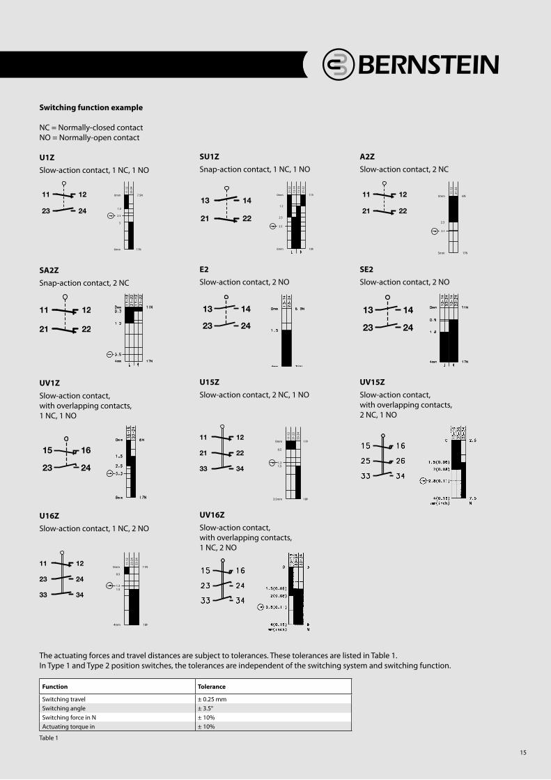
Function Tolerance
Switching travel ± 0.25 mmSwitching angle ± 3.5°Switching force in N ± 10%Actuating torque in ± 10%
Table 1
Switching function example
NC = Normally-closed contactNO = Normally-open contact
U1Z
Slow-action contact, 1 NC, 1 NO
SA2Z
Snap-action contact, 2 NC
UV1Z
Slow-action contact,with overlapping contacts,1 NC, 1 NO
U16ZSlow-action contact, 1 NC, 2 NO
SU1Z
Snap-action contact, 1 NC, 1 NO
E2Slow-action contact, 2 NO
U15ZSlow-action contact, 2 NC, 1 NO
UV16Z
Slow-action contact,with overlapping contacts,1 NC, 2 NO
A2ZSlow-action contact, 2 NC
SE2Slow-action contact, 2 NO
UV15Z
Slow-action contact, with overlapping contacts, 2 NC, 1 NO
The actuating forces and travel distances are subject to tolerances. These tolerances are listed in Table 1.In Type 1 and Type 2 position switches, the tolerances are independent of the switching system and switching function.
15

Common Features of Electromechanical Switches
p = Mechanical positive opening action
The term positive opening action refers to contact separation as the direct result of defined movement of the switch actuator by means of non-sprung parts. All parts involved in contact separation must be form-fit connected. The positive opening distance describes the minimum travel distance from the start of actuation of the operating element up to the point where positive opening action of the opening contacts is completed.
DIN EN 60947-5-1 defines two types of po- sitive opening action contacts with 4 con-nections and double break.
Type Za
l Positively opening contacts not galvanically isolated
Type Zbl Positively opening contacts galvanically isolated
Galvanic isolation describes the isolation of electrically conducted parts by insulating material or by air gaps.
In switching devices with several contact elements, galvanically isolated contact elements make it possible to switch volta-ges with different potential (e.g. normally-closed contact in safety circuit, normally-open contact for indicator).
In accordance with applicable health and safety requirements, protective devices (guards) must be mounted on machines, devices and systems that perform hazar- dous movements. Safety switches in the form of electromechanical switching devices are predominantly used for this purpose as they offer the following advantages:
l High degree of safety
l Non-susceptibility to interference
l Safety status easily checked on site
l Rational solutions
Form-fit, mechanical drives or coupling elements in the form of levers, rods, gearwheels etc. are necessary to ensure optimum operation of these safety components.
Switching devices that are used for safety functions must be identified with the symbol p internationally standardised in accordance with DIN EN 60947-5-1.In defining the class of switching devices, this symbol denotes two important proper- ties that must be met for personal protection applications:
l Mechanical positive opening action
l Disruptive breakdown voltage > 2.5 kV
Disruptive breakdown voltage
In accordance with DIN EN 60947-5-1, the open contacts must be able to maintain a minimum surge voltage of 2.5 kV without disruptive breakdown.
16

Technical data
Electrical data
Rated insulation voltage Ui max. 250 V ACConventional thermal current (up to) 1 Ithe 10 ARated operating voltage Ue max. 240 VUtilization category (up to) 1 AC-15, Ue/Ie 240 V/3 AShort-circuit protection (up to) 1 Fuse 10 A gL/gGProtection class II, Insulated
Mechanical data
Enclosure material Thermoplastic, glass fibre-reinforced (UL 94-V0)Ambient temperature -30 °C to +80 °C Mechanical service life (up to) 1 10 x 106 switching cyclesB10d (up to) 1 20 Mio.Switching frequency ≤ 100/min.Type of connection Screw connections
Conductor cross sections Single-wire 0.5 - 1.5 mm2 or Stranded wire with ferrule 0.5 – 1.5 mm2
Cable entry 1 x M20 x 1,5
Standards
VDE 0660 T100, DIN EN 60947-1, IEC 60947-1 VDE 0660 T200, DIN EN 60947-5-1, IEC 60947-5-1
Insulation-Enclosed Limit Switches
I88
Product advantages l Standard switch conforming to DIN EN 50047
l Standard actuator conforming to DIN EN 50047, Type A, B, C, E
l Protection class IP65 to VDE 0470 T1
l Enclosure and cover PA 6, self-extinguishing (UL-94-V0)
l Actuator can be repositioned by 4 x 90°
l Cable entry M20 x 1.5
l Connection designation conforming to DIN EN 50013
Options l Available with M12 connector
l AS interface variants available
l Cable entry M16 x 1.5
Design layout l Slow-action and snap-action contacts
l Versions: 1 NC/1NO, 2 NC, 2 NO, overlapping contacts
l All NC contacts with p in the circuit diagram are positively opening contacts
l Type: Zb (galvanically isolated changeover contact)
l Latching function on request
Mounting l Two M4 screws (distance between centres 22 mm),
adjustment with slots
l Two M5 screws for safety applications without additional fixing element (Fig. 1)
l Additionally secured by guide plate for lateral approach forces (Fig. 2)
l Front mounting (depending on type, Fig. 3)
Installation advantages l Snap-on cover can be released with screwdriver
l Cover opening range 135° (cover can also be detached from hinge)
l Cover protects switching element during installation
l Screw connections with self-lifting clamping plates
l Easy-action cover lock (close and press)
l Cover additionally secured with screwFig. 2
Fig. 1
Fig. 3
Recommended use Thanks to its standard dimensions as well as its wide range of contacts and actuators, this switch can be used on safety facilities and for position monitoring in virtually any industrial application.
1 Depending on switching system. See Table on Pages 76-79.
32

Switching operation
2 NC contacts
2 NO contacts
1 NC / 1 NO contact
Approvals
1 NC / 1 NO contactOverlapping
6086167018I88-SU1Z RIWK
Snap-action
Replacement actuator: 3918161672
Special features/variants (on request)
l Available with black enclosure
l With latching function
l With steel roller and following contacts: 2 NC /1 NO contact 1 NC /2 NO contact
l Both with overlap
U
6086817071I88-E2 RIWK
6086817087I88-A2Z RIWK
6086117017I88-U1Z RIWK
Slow-action
(1.0
4")
26.
5 (3.3
7")
85.
5
(0.13")
3
(0.39")
Ø10
(0.39")
10
RIWK (Form C)
6086153012I88-SU1Z W
Snap-action
Replacement actuator: -
Special features/variants (on request)
l Available with black enclosure
l With latching function and following contacts: 2 NC /1 NO contact 1 NC /2 NO contact
l Both with and without overlap
U
6086303011I88-UV1Z W
6086803014I88-E2 W
6086803013I88-A2Z W
6086103008I88-U1Z W
Slow-action
(2.9
1")
74
(0.39")
10
(0.7
8")
20
(0.31")
Ø8
W (Form B)
33

Switching operation
2 NC contacts
2 NO contacts
1 NC / 1 NO contact
Approvals
1 NC / 1 NO contactOverlapping
(1.2
2")
31
(3.6
2")
92
(0.13")
3
(0.55")
Ø14
(0.39")
10
KNW RO22RIWL
U U
Replacement actuator: -
Special features/variants(on request)
Replacement actuator: 3918161673
Special features/variants (on request)
l Available with black enclosure
l With latching function
l Available with different actuating directions
l With steel roller
6086117050I88-U1Z RIWL
6086167051I88-SU1Z RIWL
6186127112I88-U1Z KNW RO22
6086177053I88-SU1Z KNW RO22
6086817072I88-A2Z RIWL
6186827246I88-A2Z KNW RO22
6086817069I88-E2 RIWL
Slow-action Snap-action Slow-action Snap-action
21
–22
13
–14
13
–14
21
–22
4 N
7 N0 mm
5,5
7,8
2,5
I88
34
(3.5
4")
90
(0.22")
5.5
(1.2
0")
30.
5
(0.43")
Ø11
(0.39")
10
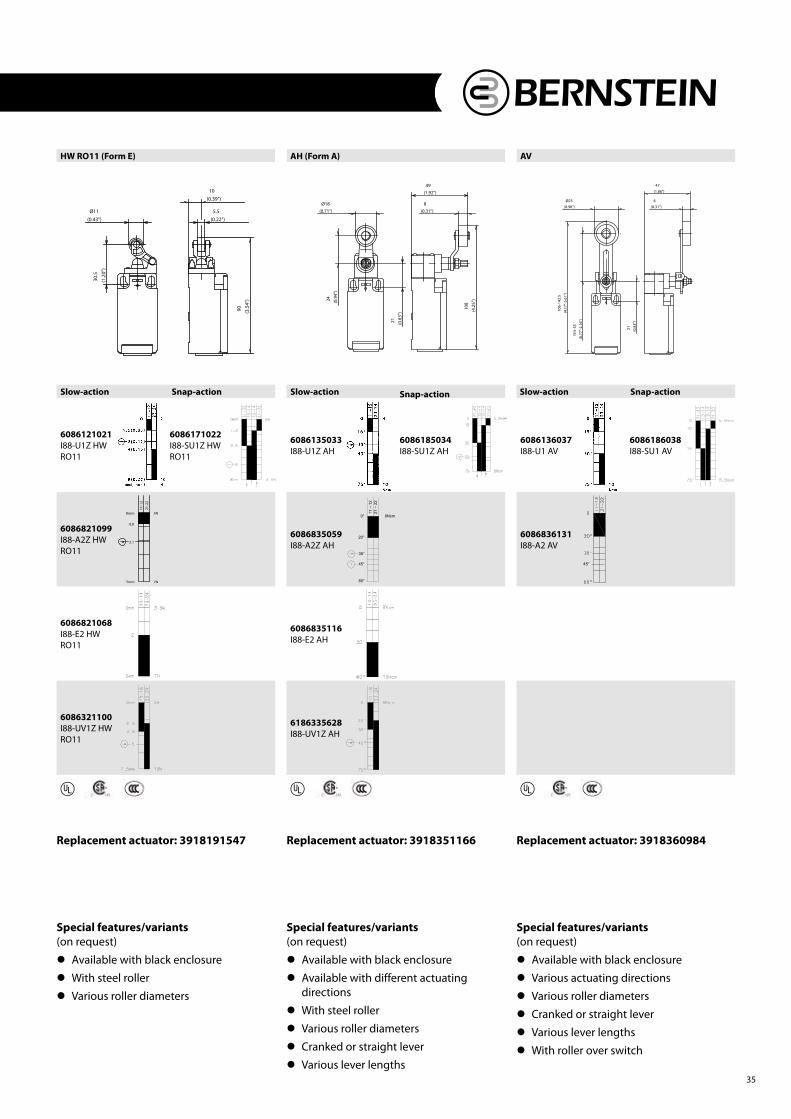
HW RO11 (Form E)
U
Replacement actuator: 3918191547
Special features/variants (on request)
l Available with black enclosure
l With steel roller
l Various roller diameters
6086121021I88-U1Z HW RO11
6086171022I88-SU1Z HW RO11
6086821099I88-A2Z HW RO11
6086821068I88-E2 HW RO11
6086321100I88-UV1Z HW RO11
Slow-action Snap-action
(4.1
7"-5
.61"
)
106
-142
.5
(0.98")
Ø25
(0.7
7"-2
.16"
)
19
.5-5
5
(0.8
3")
21
(1.86")
47
(0.31")
8
(0.71")
Ø18
(0.9
4")
24
(0.8
3")
21
(1.92")
49
(0.31")
8
(4.2
5")
108
AVAH (Form A)
Slow-action Snap-action
6086135033I88-U1Z AH
U U
Replacement actuator: 3918351166
Special features/variants (on request)
l Available with black enclosure
l Available with different actuating directions
l With steel roller
l Various roller diameters
l Cranked or straight lever
l Various lever lengths
Replacement actuator: 3918360984
Special features/variants (on request)
l Available with black enclosure
l Various actuating directions
l Various roller diameters
l Cranked or straight lever
l Various lever lengths
l With roller over switch
6086185034I88-SU1Z AH
6086136037I88-U1 AV
6086186038I88-SU1 AV
6086835059I88-A2Z AH
8Ncm
11
–12
21
–22
0°
35°
80°
20°
45°
6086836131I88-A2 AV
45°
6086835116I88-E2 AH
6186335628I88-UV1Z AH
Slow-action Snap-action
35

Switching operation
2 NC contacts
2 NO contacts
1 NC / 1 NO contact
Approvals
1 NC / 1 NO contactOverlapping
(0.71"-0.94")
18-24
(0.83")
21
(0.8
7")
Ø22
(1.5
9")
40.
5
(4.1
5")
105
.5
(0.20")
5
(0.39")
10(0.24"-0.47")
6-12
(0.35")
9
(0.8
7")
Ø22
(1.5
9")
40.
5
(4.1
5")
105
.5
(0.20")
5
(0.39")
10
DGKW RO22DGHW RO22
U U
Replacement actuator: 3918271528
Special features/variants (on request)
l With latching function
l Various roller diameters and with following contacts: 2 NC /1 NO contact 1 NC /2 NO contact Both with overlap
Replacement actuator: 3918211529
Special features/variants (on request)
l Available with black enclosure
l Available with different actuating directions
l Various roller diameters
6086121029I88-U1Z DGHW RO22
6086171030I88-SU1Z DGHW RO22
6086127025I88-U1Z DGKW RO22
6086177026I88-SU1Z DGKW RO22
6086821120I88-A2Z DGHW RO22
6186321244I88-UV1Z DGHW RO22
Darg for
Slow-action Snap-action Slow-action Snap-action
I88
36

FF
Replacement actuator: 3918401031
Special features/variants (on request)
l Available with black enclosure
l Various spring lengths
l Different spring versions or spring rod
6186140217I88-U1 FF
6086190078I88-SU1 FF
Slow-action Snap-action
Withdrawactuatorn
Insertactuator
W RASTKS
Slow-action Snap-action
6116819140I88-U1Z KS
U U
Replacement actuator: -
Special features/variants (on request)
Replacement actuator: -
Special features/variants(on request)
Withdrawactuator
Inser tactuator
6186103005I88-U1Z W RAST Latch
6186803155I88-A2Z W RAST
Latch
Slow-action
37