commissioning process of water flow glazing facadesoa.upm.es/55112/1/flow_glazing_facades.pdftest...
TRANSCRIPT
Commissioning process of water flow glazing facades
Diego García Department of Applied Mathematics, School of Aeronautics and Space Engineering. Technical University of Madrid (UPM),
[email protected] ORCID: 0000-0002-5426-6184
Belen Moreno
Department of Applied Mathematics, School of Aeronautics and Space Engineering. Technical University of Madrid (UPM), [email protected]
ORCID: 0000-0001-7564-4765
Juan A. Hernández Department of Applied Mathematics, School of Aeronautics and Space Engineering. Technical University of Madrid (UPM),
[email protected] ORCID: 0000-0002-5188-1456
Cite this paper as: Diego García, Belén Moreno, Juan A. Hernández. Commissioning process of water flow glazing
facades. 7th Eur. Conf. Ren. Energy Sys. 10-12 June 2019, Madrid, Spain
Abstract: The objective of commissioning is to provide documented confirmation that a facility fulfils functional and performance requirements. Commissioning recognizes the integrated nature of water flow glazing systems performance. Commissioning is carried out to prove that systems operate and perform to the design intent and specification. To reach this goal, it is necessary for the commissioning process to establish and document project requirements, performance specifications, and system functions. It is important to verify and document compliance with these criteria throughout the design, proof of concept, construction, and the initial period of operation. The commissioning process works in conjunction with the project design team through the design stage and the construction stage. It prepares a commissioning plan and final commissioning results. The main results of this work are the elaboration of detailed checklists for the design and the construction stages to assure that the water flow glazing facade is properly installed, started and checked out. During the installation, various tests are undertaken known as static testing. Upon completion of static testing, dynamic testing is undertaken. Generally, during the integration process, some equipment of the primary circuit is inoperative. Hence, emulation or simulation of specific equipment is needed to prove that the water ow glazing facade operates in accordance with specifications. In this work, functional tests are established to evaluate the thermal performance and operation of the equipment. Automation software and hardware platform are used to monitor thermal and comfort requirements and to expedite the commissioning process. The fulfilment of commissioning procedures for the project is recorded at the end of the construction phase.
Keywords: Commissioning, specification, checklist, water flow glazing facade © 2019 Published by ECRES
Nomenclature WFG PCB IEA
ECBCS
Water Flow Glazing Printed Circuit Board International Energy Agency Energy Conservation in Buildings and Community Systems
7th EUROPEAN CONFERENCE ON RENEWABLE ENERGY SYSTEMS Madrid/Spain 10-12 June 2019
1. INTRODUCTION The Paris Agreement [1] aims, specifically in the European Union [2], to improve the energy performance of buildings, considering outdoor climatic conditions, as well as indoor climate requirements and cost-effectiveness. Approximately one third of the total worldwide energy consumption is consumed in buildings [3]. Commissioning process is an effective method to ensure that buildings reach their operating potential, guaranteeing that advanced components and systems reach their technical specifications and operate energy-efficiently. To reach this, many of the commissioning tools are focused on fault detection and diagnosis, followed by optimization, design and data management [4]. Two different analysis approaches are presented to implement commissioning on all kind of buildings [5]:
• The top-down approach, which consists in a breakdown from the whole building level to component level, through some subsystems. The first labour of this approach is to check if the general performance of the system and the interaction between components and subsystems is satisfactory or within the “normal” range.
• The bottom-up approach, which begins with the analysis of a single component and moves forward, progressively, to the entire building level. It is unfeasible to control the operation of all building components. It is therefore essential that, before the implementation of the bottom-up approach, priorities are established for the investigation of representative samples of those components for which a failure is either probable or would have the greatest effect on the properties of the building.
These approaches can be carried out in both new low energy buildings and existing buildings. Commissioning for new constructions may be introduced in the design phase, guaranteeing the building owner and the design engineer liberty in their decisions. However, when commissioning existing constructions, design and functional data is often unavailable, inaccurate or incorrect. Although it is possible to create detailed documentation or place numerous sensors to measure data for the analysis, the cost is considered too high for this to become standard methodology in existing buildings. Thus, tools for existing buildings often count on data which is either already accessible or that can be collected at low cost. Consequently, the suitable analysis approach for an existing building (top-down or bottom-up) is selected depending on the accessibility of these data [4]. Although there are international differences in the needs for commissioning tools, this text will focus on the needs from European point of view. In Europe the appellation “commissioning” is less widespread and for many of its countries the situation for existing and new constructions is very dissimilar. For existing buildings there is no general standardization agreement yet, therefore, commissioning services are usually individual approaches based on a company’s know-how. For new buildings, in most cases commissioning is only executed during the handover as primary commissioning. This is usually performed by the builder or designer. In many cases this first commissioning is only an inexact check of integrity of installation and principal functionality. Nevertheless, a commissioning procedure described in the IEA ECBCS Annex 40 [6] for new constructions is unusual. Water Flow Glazing is an envelope for new low energy buildings. As a part of a construction it is necessary to carry out a commissioning process to assess its components and ensure that works correctly. The commissioning of WFG modules has three different stages, which are the design stage, the production stage and the construction stage. It is important to understand that the commissioning process of WFG modules is not the same as the commissioning of the facility where these modules will be installed. While commissioning of WFG modules ends when its construction stage finishes, the commissioning of the facility will continue along time to assure that the whole system works without suitably. Next, it is explained the commissioning process of a new WFG module, which is implemented by means of a bottom-up analysis approach.
7th EUROPEAN CONFERENCE ON RENEWABLE ENERGY SYSTEMS Madrid/Spain 10-12 June 2019
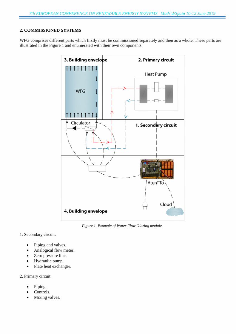
2. COMMISSIONED SYSTEMS WFG comprises different parts which firstly must be commissioned separately and then as a whole. These parts are illustrated in the Figure 1 and enumerated with their own components:
Figure 1. Example of Water Flow Glazing module.
1. Secondary circuit.
• Piping and valves. • Analogical flow meter. • Zero pressure line. • Hydraulic pump. • Plate heat exchanger.
2. Primary circuit.
• Piping. • Controls. • Mixing valves.

7th EUROPEAN CONFERENCE ON RENEWABLE ENERGY SYSTEMS Madrid/Spain 10-12 June 2019
3. Building envelope.
• Glazing. • Frame and subframe. • Assembling and construction joints. • Modular unit. • Registers.
4. Hardware and software systems.
• Central building automation system. • Temperature probes. • Electrical power. • OneWire data buses. • DC power wiring for pumps. • Data communications. Ethernet connections. • Remote services based on monitoring. • InDeWaG software tool.
Depending on the complexity of the facility, emphasis must be put in different areas and systems. These areas comprise the modular unit, its connection with the primary circuit and assembling, construction details, the electronic control unit and remote services based on monitoring data. Besides, since the InDeWaG software tool is a key requirement to design WFG facades, commissioning for the software project is also implemented. 3. DESIGN STAGE Automating portions of the commissioning process is one approach to improving cost-effectiveness. In our case it is done by means of the AtenTTo platform and a proper selection of temperature probes and on-line electrical measurements. In commissioning WFG facade, performance tests are needed to explicitly address energy consumption at the system or whole building level and the peak demand. The innovative WFG facade requires functional test procedures that are customized to the design specifications. The commissioning specification will include general commissioning requirements common to all systems and assemblies and a detailed description of the responsibilities of all parties. Reporting and documentation requirements, alerts to coordination issues, deficiency resolution, construction checklist and start-up requirements are also required. The specifications will clearly indicate who is witnessing and documenting start-up of each commissioned system. The following enumerated list is a guideline to deal with the commissioning process at the design stage:
1. Assemble commissioning team and identify responsibilities. 2. Review the Preliminary Commissioning Plan. 3. Schedule and lead commissioning meetings. 4. Coordinate the commissioning work during design. 5. Review Project Requirements and basis of designs. 6. Develop full commissioning specifications for all commissioned equipment. 7. Review the project specifications and provide comments, submittal requirements, test, operations and
maintenance and system manual requirements. 8. Coordinate an integration meeting. 9. Review the recommendations from the constructability issues. 10. Write step-by-step functional test procedures and documentation formats for all commissioned equipment
and assemblies. Test procedures will include manual functional testing, energy management control system and include stand-alone data-logger monitoring.
7th EUROPEAN CONFERENCE ON RENEWABLE ENERGY SYSTEMS Madrid/Spain 10-12 June 2019
3.1. Status check sheet Commissioning status check lists are organized in a summary basis that track the progress of equipment and system. Commissioning during the design phase is intended to achieve the following specific objectives:
1. Ensure that the design and operational intent are clearly documented. 2. Ensure that recommendations for improvements are communicated to the design team during design to aid
the development of commissioning and avoid later contract modifications. 3. Ensure that commissioning for the construction phase is adequately reflected in the construction documents.
The following check lists cover this design stage.
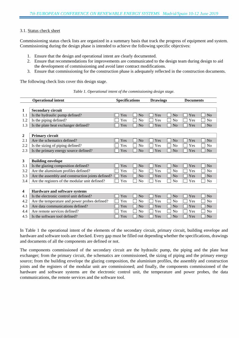
Table 1. Operational intent of the commissioning design stage.
Operational intent Specifications Drawings Documents 1 Secondary circuit 1.1 Is the hydraulic pump defined? Yes No Yes No Yes No 1.2 Is the piping defined? Yes No Yes No Yes No 1.3 Is the plate heat exchanger defined? Yes No Yes No Yes No 2 Primary circuit 2.1 Are the schematics defined? Yes No Yes No Yes No 2.2 Is the sizing of piping defined? Yes No Yes No Yes No 2.3 Is the primary energy source defined? Yes No Yes No Yes No 3 Building envelope 3.1 Is the glazing composition defined? Yes No Yes No Yes No 3.2 Are the aluminium profiles defined? Yes No Yes No Yes No 3.3 Are the assembly and construction joints defined? Yes No Yes No Yes No 3.4 Are the registers of the modular unit defined? Yes No Yes No Yes No 4 Hardware and software systems 4.1 Is the electronic control unit defined? Yes No Yes No Yes No 4.2 Are the temperature and power probes defined? Yes No Yes No Yes No 4.3 Are data communications defined? Yes No Yes No Yes No 4.4 Are remote services defined? Yes No Yes No Yes No 4.5 Is the software tool defined? Yes No Yes No Yes No
In Table 1 the operational intent of the elements of the secondary circuit, primary circuit, building envelope and hardware and software tools are checked. Every gap must be filled out depending whether the specifications, drawings and documents of all the components are defined or not.
The components commissioned of the secondary circuit are the hydraulic pump, the piping and the plate heat exchanger; from the primary circuit, the schematics are commissioned, the sizing of piping and the primary energy source; from the building envelope the glazing composition, the aluminium profiles, the assembly and construction joints and the registers of the modular unit are commissioned; and finally, the components commissioned of the hardware and software systems are the electronic control unit, the temperature and power probes, the data communications, the remote services and the software tool.
7th EUROPEAN CONFERENCE ON RENEWABLE ENERGY SYSTEMS Madrid/Spain 10-12 June 2019
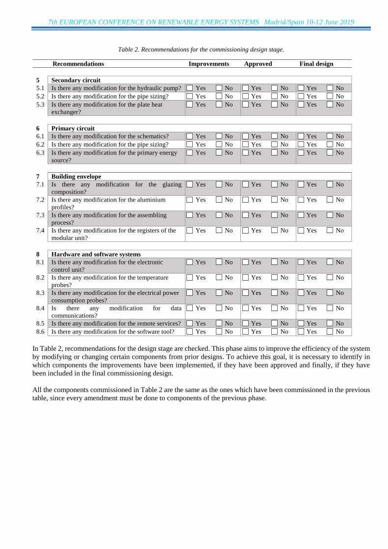
Table 2. Recommendations for the commissioning design stage.
Recommendations Improvements Approved Final design 5 Secondary circuit 5.1 Is there any modification for the hydraulic pump? Yes No Yes No Yes No 5.2 Is there any modification for the pipe sizing? Yes No Yes No Yes No 5.3 Is there any modification for the plate heat
exchanger? Yes No Yes No Yes No
6 Primary circuit 6.1 Is there any modification for the schematics? Yes No Yes No Yes No 6.2 Is there any modification for the pipe sizing? Yes No Yes No Yes No 6.3 Is there any modification for the primary energy
source? Yes No Yes No Yes No
7 Building envelope 7.1 Is there any modification for the glazing
composition? Yes No Yes No Yes No
7.2 Is there any modification for the aluminium profiles?
Yes No Yes No Yes No
7.3 Is there any modification for the assembling process?
Yes No Yes No Yes No
7.4 Is there any modification for the registers of the modular unit?
Yes No Yes No Yes No
8 Hardware and software systems 8.1 Is there any modification for the electronic
control unit? Yes No Yes No Yes No
8.2 Is there any modification for the temperature probes?
Yes No Yes No Yes No
8.3 Is there any modification for the electrical power consumption probes?
Yes No Yes No Yes No
8.4 Is there any modification for data communications?
Yes No Yes No Yes No
8.5 Is there any modification for the remote services? Yes No Yes No Yes No 8.6 Is there any modification for the software tool? Yes No Yes No Yes No
In Table 2, recommendations for the design stage are checked. This phase aims to improve the efficiency of the system by modifying or changing certain components from prior designs. To achieve this goal, it is necessary to identify in which components the improvements have been implemented, if they have been approved and finally, if they have been included in the final commissioning design. All the components commissioned in Table 2 are the same as the ones which have been commissioned in the previous table, since every amendment must be done to components of the previous phase.

7th EUROPEAN CONFERENCE ON RENEWABLE ENERGY SYSTEMS Madrid/Spain 10-12 June 2019
Table 3. Construction documents of the commissioning design stage.
Construction documents Sequence Plans Details 9 Secondary circuit 9.1 Is the gluing between elements defined? Yes No Yes No Yes No 9.2 Is the complete circulator defined? Yes No Yes No Yes No 10 Primary circuit 10.1 Is the piping schematic defined? Yes No Yes No Yes No 10.2 Is the primary energy source defined? Yes No Yes No Yes No 11 Building envelope 11.1 Is the glazing assembly defined? Yes No Yes No Yes No 11.2 Is the assembly of the aluminium profiles defined? Yes No Yes No Yes No 11.3 Are the registers of the modular unit defined? Yes No Yes No Yes No 12 Hardware and software systems 12.1 Is the bill of materials defined? Yes No Yes No Yes No 12.2 Is the PCB defined? Yes No Yes No Yes No 12.3 Are the power consumption probes defined? Yes No Yes No Yes No 12.4 Are data communications defined? Yes No Yes No Yes No 12.5 Is the software tool defined? Yes No Yes No Yes No
Table 3 represents the last phase of the commissioning design stage. Its aim is to create detailed documents for the construction phase according to the specifications written in the previous phases. In this case it is checked if sequence documents, plans and detail documents exist for every part of the system. The components or procedures commissioned in this table according to the secondary circuit, the gluing between elements and the circulator; to the primary circuit, the piping schematic and the primary energy source; to the building envelope, the glazing assembly, the assembly of the aluminium profiles and the registers of the modular unit; and eventually, according to the hardware and software systems, the bill of the materials, the PCB, the power consumption probes, the data communications and the software tool. 3.2. Timing list Commissioning shall start at the design stage and it cannot be left until the end of construction. Order and timing are a list of each commissioning activity including duration and sequence allowing commissioning to proceed logically. Once this timing is created, each activity is integrated into the project construction schedule. The circulator which comprises the hydraulic heat pump and the plate heat exchanger together with its proof of concept must be commissioned before modular units are produced. However, the proof of concept of the aluminium frame and sub-frame can be commissioned in parallel. The same is applicable to the electronic control unit, the software tool and the remote software services. Once the modular unit is commissioned is produced, commissioning at construction stage can be done. Commissioning agent uses the order and timing list to track the progress of commissioning. The following order and timing list are created as an example of how to integrate all activities during a project.
7th EUROPEAN CONFERENCE ON RENEWABLE ENERGY SYSTEMS Madrid/Spain 10-12 June 2019
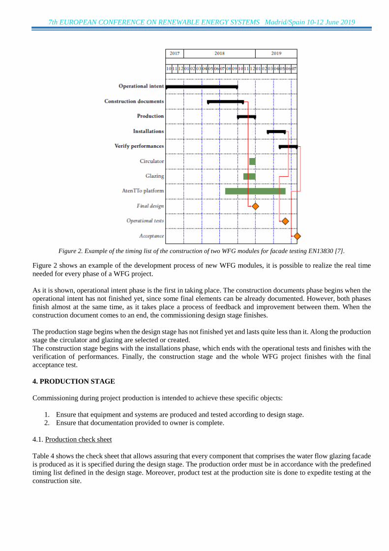
Figure 2. Example of the timing list of the construction of two WFG modules for facade testing EN13830 [7].
Figure 2 shows an example of the development process of new WFG modules, it is possible to realize the real time needed for every phase of a WFG project. As it is shown, operational intent phase is the first in taking place. The construction documents phase begins when the operational intent has not finished yet, since some final elements can be already documented. However, both phases finish almost at the same time, as it takes place a process of feedback and improvement between them. When the construction document comes to an end, the commissioning design stage finishes. The production stage begins when the design stage has not finished yet and lasts quite less than it. Along the production stage the circulator and glazing are selected or created. The construction stage begins with the installations phase, which ends with the operational tests and finishes with the verification of performances. Finally, the construction stage and the whole WFG project finishes with the final acceptance test. 4. PRODUCTION STAGE Commissioning during project production is intended to achieve these specific objects:
1. Ensure that equipment and systems are produced and tested according to design stage. 2. Ensure that documentation provided to owner is complete.
4.1. Production check sheet Table 4 shows the check sheet that allows assuring that every component that comprises the water flow glazing facade is produced as it is specified during the design stage. The production order must be in accordance with the predefined timing list defined in the design stage. Moreover, product test at the production site is done to expedite testing at the construction site.

7th EUROPEAN CONFERENCE ON RENEWABLE ENERGY SYSTEMS Madrid/Spain 10-12 June 2019
Table 4. Checklist of the commissioning production stage.
Production Order Manufacturing Product test 13 Secondary circuit 13.1 Is the hydraulic pump specified? Yes No Yes No Yes No 13.2 Is the piping specified? Yes No Yes No Yes No 13.3 Is the plate heat exchanger specified? Yes No Yes No Yes No 14 Primary circuit 14.1 Is the sizing of piping specified? Yes No Yes No Yes No 14.2 Is the primary energy source specified? Yes No Yes No Yes No 15 Building envelope 15.1 Is the glazing composition specified? Yes No Yes No Yes No 15.2 Are the aluminium profiles specified? Yes No Yes No Yes No 15.3 Are the assembly and construction joints
specified? Yes No Yes No Yes No
15.4 Are the registers of the modular unit specified? Yes No Yes No Yes No 16 Electrical systems 16.1 Is the electronic control unit specified? Yes No Yes No Yes No 16.2 Are the temperature probes specified? Yes No Yes No Yes No 16.3 Are the electrical power consumption probes
specified? Yes No Yes No Yes No
16.4 Are remote services specified? Yes No Yes No Yes No 16.5 Is the software tool specified? Yes No Yes No Yes No
5. CONSTRUCTION STAGE Commissioning during project construction is intended to achieve these specific objects: 1. Ensure that applicable equipment and systems are installed properly and receive adequate operational tests by installing contractors. 2. Verify and document proper performance of equipment and systems through normal and other likely operational modes necessary to meet design intent. 3. Ensure that documentation provided to owner is complete. To assure these objectives, the following enumerated list is a guideline to deal with the commissioning process at the construction stage:
1. Coordinate the commissioning work with the design team and construction manager, to ensure that commissioning activities are being incorporated into the master schedule.
2. Revise the construction phase commissioning plan developed during design, including scope and schedule. 3. Plan and conduct commissioning meetings as needed and distribute minutes. 4. Request and review additional information required to perform commissioning tasks, contractor start-up and
checkout procedures. 5. Review submittal applicable to systems being commissioned for compliance with commissioning needs,
concurrent with the design team and Construction Manager reviews. 6. Review coordination drawings to ensure that trades are making a reasonable effort to coordinate. 7. Write and distribute construction checklists for commissioned equipment. 8. Develop an enhanced start-up and initial systems checkout plan with contractors for selected equipment. 9. Perform site visits to observe component and system installations. Review construction meeting minutes for
revisions/ substitutions relating to the commissioning process. Assist in resolving any discrepancies. 10. Include testing documentation in the Commissioning Record.

7th EUROPEAN CONFERENCE ON RENEWABLE ENERGY SYSTEMS Madrid/Spain 10-12 June 2019
11. Document construction checklist completion by reviewing completed construction checklists and by selected site observation.
12. Document systems start-up by reviewing start-up reports and by selected site observation. 13. Witness and document manual functional performance tests performed for all commissioned systems and
assemblies. 14. After manual testing and initial trouble shooting is complete, monitor system operation and performance for
selected data from remote services. Analyse monitored data to verify operation and performance and issue a written report.
5.1. Installation check sheet Once the equipment is received, static tests allow understanding if the equipment or system is properly installed. Modular unit installations are firstly inspected to check if the required parameters are kept. Subsequently, primary circuit required for modular unit starting and operation is checked, as it is shown in Table 5. The following tasks are carried out:
1. Visual inspection of the main piping connections to the glazing. 2. Check DC power connections and temperature probes. 3. Test temperature measurements by means of AtenTTo platform. 4. Check electrical protection testing. 5. Check DC power for the hydraulic pumps of modules. 6. Check hydraulic pump running. 7. Check the operating parameters: flow rate, inlet and outlet temperature.
Table 5. Checklist of the installation process.
Installations Reception Installation Static test 17 Secondary circuit 17.1 Is the modular unit operative? Yes No Yes No Yes No 18 Primary circuit 18.1 Is the primary energy source operative? Yes No Yes No Yes No 19 Building envelope 19.1 Are the assembly and construction joints
operative? Yes No Yes No Yes No
19.2 Are the registers of the modular unit operative? Yes No Yes No Yes No 20 Electrical systems 20.1 Is the electronic control unit operative? Yes No Yes No Yes No 20.2 Are data communications operative? Yes No Yes No Yes No 20.3 Are remote services operative? Yes No Yes No Yes No 20.4 Is the software tool operative? Yes No Yes No Yes No
5.2. System start-up notification As soon as the correct operation is tested and confirmed, the commissioning work is considered completed and the equipment is handed over to the customer with a record. Table 6 presents the checklist that the customer must complete to ensure that the module has been correctly handed over.
7th EUROPEAN CONFERENCE ON RENEWABLE ENERGY SYSTEMS Madrid/Spain 10-12 June 2019
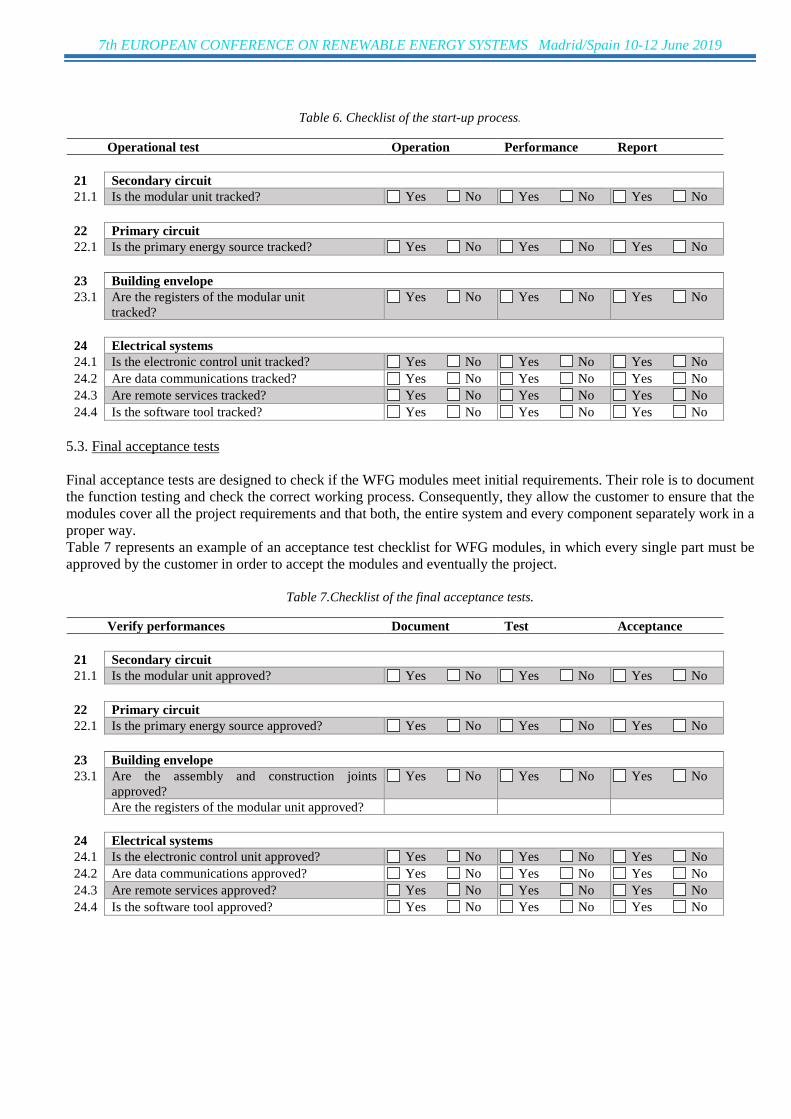
Table 6. Checklist of the start-up process.
Operational test Operation Performance Report 21 Secondary circuit 21.1 Is the modular unit tracked? Yes No Yes No Yes No 22 Primary circuit 22.1 Is the primary energy source tracked? Yes No Yes No Yes No 23 Building envelope 23.1 Are the registers of the modular unit
tracked? Yes No Yes No Yes No
24 Electrical systems 24.1 Is the electronic control unit tracked? Yes No Yes No Yes No 24.2 Are data communications tracked? Yes No Yes No Yes No 24.3 Are remote services tracked? Yes No Yes No Yes No 24.4 Is the software tool tracked? Yes No Yes No Yes No
5.3. Final acceptance tests Final acceptance tests are designed to check if the WFG modules meet initial requirements. Their role is to document the function testing and check the correct working process. Consequently, they allow the customer to ensure that the modules cover all the project requirements and that both, the entire system and every component separately work in a proper way. Table 7 represents an example of an acceptance test checklist for WFG modules, in which every single part must be approved by the customer in order to accept the modules and eventually the project.
Table 7.Checklist of the final acceptance tests.
Verify performances Document Test Acceptance 21 Secondary circuit 21.1 Is the modular unit approved? Yes No Yes No Yes No 22 Primary circuit 22.1 Is the primary energy source approved? Yes No Yes No Yes No 23 Building envelope 23.1 Are the assembly and construction joints
approved? Yes No Yes No Yes No
Are the registers of the modular unit approved? 24 Electrical systems 24.1 Is the electronic control unit approved? Yes No Yes No Yes No 24.2 Are data communications approved? Yes No Yes No Yes No 24.3 Are remote services approved? Yes No Yes No Yes No 24.4 Is the software tool approved? Yes No Yes No Yes No

7th EUROPEAN CONFERENCE ON RENEWABLE ENERGY SYSTEMS Madrid/Spain 10-12 June 2019
6. RESULTS AND DISCUSSION The main result of this work is the elaboration of detailed checklists that will lead the commissioning process of the water flow glazing modules (Tables 1-7). These checklists must be specified for every phase of every stage of the commissioning process, assuring that the water flow glazing facade is properly designed, produced, constructed and eventually, installed and accepted by the customer. As a result of the checklists, it is possible to create two different handbooks to ease the performance of the commissioning. The first handbook is intended for the project developer and must contain all the checklists regarding the design, production and initial construction stages, namely, checklists form Table 1 to Table 5. The second handbook is intended for the customer or owner of the water flow glazing modules and must contain the Table 6 and 7. This handbook must be a tool that allows the customer to check that the whole system works correctly and eventually, to accept it. 7. CONCLUSIONS Commissioning is a tool that allows ensuring that every phase of the project performs progressively and correctly, permits implementing a feedback process between different phases of the project development and finally, permits assuring that the customer is satisfied with the product and accept it. Commissioning no longer must be seen just as a checking process but as a procedure that allows systems and components to reach their technical potential and to operate energy-efficiently. Moreover, it has been identified by an international research [4] that the lack of commissioning practices in projects means a crucial obstruction to market penetration of their products. For all these reasons, commissioning has become an essential tool for every project whose purpose is to create, develop or maintain new or existing installations. ACKNOWLEDGMENT This work was supported by program Horizon 2020-EU.3.3.1.: Reducing energy consumption and carbon footprint by smart and sustainable use, project ref. 680441 InDeWaG: Industrial Development of Water Flow Glazing Systems. REFERENCES [1] U.N. Paris Agreement, Paris agreement, United Nations Framework Convention on Climate Change, Paris 5, 2016 October 2016. [2] Directive 2010/31/EU, E.P.C., Directive 2010/31/eu on the energy performance of buildings, Off. J. Eur. Union (2010) 23 18 June 2010. [3] Moreno B, Hernández JA, Analytical solutions to evaluate solar radiation overheating in simplified glazed romos. Elsevier 2018, 140, 162-172. <https://doi.org/10.1016/j.buildenv.2018.05.037>. [4] Neumann C, Jacob D, Peitsman H, et al. Annex 47 Report 2: Commissioning Tools for Existing and Low Energy Buildings. United States of America: 50 pages, 2012. [5] Nakahara N. Aspects of implementation. In: Hyvarinen J, Karki S, editors, Building Optimization and Fault Diagnosis Source Book, Finland: Technical Research Centre of Finland, Building Technology, 1996, pp. 306-307. [6] Akashi Y, Andre P, Bornside D, Carling P, et al. Annex 40: Commissioning of Buildings and HVAC Systems for Improved Energy Performance, Birmingham, United Kingdom: AECOM, International Energy Agency, 2004. [7] EN 13830. Curtain walling – Product standard. European Committee for Standardization (CEN) (2018) 1 September 2018.