commissioning guide - swegon archive/air diffusers/k-factors/_en... · this commissioning guide...
TRANSCRIPT

Commissioning GuideVersion 2010:07
Air diffusersFlow controlClimate systems

2Commissioning guide 2010:07 www.swegon.com

3Commissioning guide 2010:07 www.swegon.com
Contents
Measurement and commissioning
5-6
Air diffusers with commissioning box ALS
7-17
ALC 8
CBE 8
CDD 8
CDK 9
CDR 9
CKD 10
CKP 10
CVH 11
DPG 11
EAGLE S/D 11
EIV 11
LOCKZONE B 12
LPA 12
ROC 12
COLIBRI CC 13
COLIBRI CR 14
EAGLE C 15
HAWK C 16
LOCKZONE C 17
PELICAN CS/CE 18
Air diffusers with commissioning box ALV
19-21
COLIBRI W 19
EAGLE W 19
LOCKZONE W 20
PELICAN W 20
ROW 20
Air diffusers with commissioning box TRG
21-22
ALG 21
GRL 22
GTH 22
Air diffusers with circular commissioning box
23-24
ACD 23
EAGLE F 24
LOCKZONE F 24
Displacement units 25-27DBC 25
DBR 25
DCP 26
DHC 26
DVC 26
ICP 26
IHC 26
IVC 26
DIR 27
DKC 27
DRC 27
DRI 27
Home air diffusers 28DOMO 28
Diffuser beam with discs and adjustable measuring unit
28
IBIS C 28

4Commissioning guide 2010:07 www.swegon.com
Contents
Slot diffusers 29SLAT 1 SLA 29
STAT 2 SLA 29
Linear disc diffuser with commissioning box
30
SRYT 1 SRY 30
SRYT 2 SRY 30
Extract air diffusers 31-32EXC 31
ROE 32
Flow control 33-36VAR 33
IRIS 35
CRM 1 36
CRM 5 36
Climate systems 37
Climate beams and comfort modules
37-54
BALTIC 38
BRC 38
BISCAY 39
BSA 40
PARASOL 592 MF 41
PARASOL 1192 LF/MF/HF 42
PARASOL EX/UC 690 44
PARASOL EX/UC 1290 MF/HF 45
ADRIATIC VF 46
BISCAY VF/VF-OH 50
PARAGON/PARAGON WALL -i 54

5Commissioning guide 2010:07 www.swegon.com
Measurement and commissioning
This commissioning guide shows the measurement instructions for measurable ventilation products made by Swegon AB.
The products are equipped with adjustable dampers and measuring units, which are desig-ned to measure a reference pressure.
Measurement instructions:There are several different ways to measure a product. It depends on the product and the design of the measuring function:
• Ductwork with fixed measuring unit.
• Exhaust air terminals with fixed measuring units.
• Supply air terminals with fixed measuring units.
In this commissioning guide you will find these three categories.
Most of the products have measuring tubes connected to the measuring units. The tubes can easily be reached through the front of the terminal device. Some products have one tube and some have two tubes.
A few products have what we call a ”nipple well” with a cover. The cover should be shut when balancing has been done.
Some of the flow control products do not have any measuring tubes. Instead you reach the measuring unit easily.
All the products documented together with commissioning boxes ALS, ALV and TRG must be measured together with the commissioning boxes as the measuring units are placed within those.
Procedure:1. Define the k-factor for the specific terminal by using the tables in this commissioning
guide.
2. Connect the manometer to the measuring tube(s), (measuring units, nipple well).
3. The manometer gives you a measurement pressure, pi (balancing pressure).
4. The airflow can now be calculated according to the equation on next page.
5. Adjust the damper to change the airflow. A few of the products do not have ordinary dampers. Instead you use adjustable slot openings or plastic plugs.
6. Lock the damper regulator.
When the correct flow/pressure has been achieved the damper regulator should be locked in one of the following ways:
Supply air diffusers:
1. In air terminals in which the damper position adjustment control consists of one white and one black nylon cord, the outstretched cords should be tied together to form a so-called commissioning knot. Doing so ensures that the preset damper position is always indicated
2. Wind the cords one turn around the locking screw provided in the product. Lock the damper position by tightening the screw.

6Commissioning guide 2010:07 www.swegon.com
Measurement and commissioning
Extract air diffusers:
Takes place analogous to the supply airflow. If the air device is an air extract air register, the position of the cone can be locked in position by tightening a wing nut on the rear side of the air register.
Kanalprodukter:
On the duct products in which measurement/commissioning takes place according to Met-hod A2, the damper knob is equipped with a locking device.
Calculation of airflow – k-factor equations:There is a specific balancing factor, k-factor, for each measurable Swegon product.
The products are normally marked with a k-factor.
The following equations are used to obtain the actual airflow or the balancing pressure that is valid for the designed airflow.
q = k · √ pi
(l/s)
q = measured airflow (l/s) p
i = actual balancing pressure (Pa)
k = k-factor
pi = (
q)
2(Pa)
k
pi = balancing pressure at designed airflow (Pa)
q = designed airflow (l/s) k = k-factor
If temperature and atmospheric pressure differ from standard settings (20 °C and 1013 mbar) at the time of commissioning, the balancing pressure is recalculated according to the following equation:
pi = p
i, measured ·1,2 (Pa)
rtime of measurement
Or the airflow can be recalculated to the standard settings according to:
q = qmeasured · √ 1,2 (Pa)
rtime of measurement

7Commissioning guide 2010:07 www.swegon.com
Air diffusers with commissioning box ALS
Figure 1. Measurement with one tube.
k-factorQuick AccessCEILING COLLECTION
TomelillaSweden
200-600+ALSd 160 -200/125 -200
k
qk-faktor= XX / XX
p
TILLUFT / SUPPLY AIR
TILLUFT / SUPPLY AIR
FRÅNLUFT / EXTRACT AIR
k pq ⋅=
kpq
=( )2
q = flow reading l/s p = current pressure reading (Pa) k = commissioning factor
Figure 2. Measurement with two tubes, Ceiling Collection.
Air diffusers

8Commissioning guide 2010:07 www.swegon.com
Air diffusers with commissioning box ALS
ALSd CDDb supply air 360°
Size Size Slot 20 mm
Slot 30 mm
Slot 40 mm
Tube colour
80-100 100 5,8 6,1 – Red100-125 125 8,2 8,9 – Red125-160 160 – 14,4 15,0 Red160-200 200 – 21,3 23,4 Red200-250 250 – 24,4 31,1 Red250-315 315 – 34,6 43,3 Red
1 measuring tube
ALSd ALBATROSS ALCaSize Size Supply
airTube
colour
200-250 250 30,1 Red250-315 315 42,6 Red315-400 400 59,4 Red400-500 500 78,2 Red500-630 630 153,0 Red
1 measuring tube
ALCaALSd CBEa
Size Size Supply air
Tube colour
80-100 100 4,6 Red100-125 125 7,3 Red125-160 160 11,9 Red
1 measuring tube
CBEa
CDDb
9Commissioning guide 2010:07 www.swegon.com
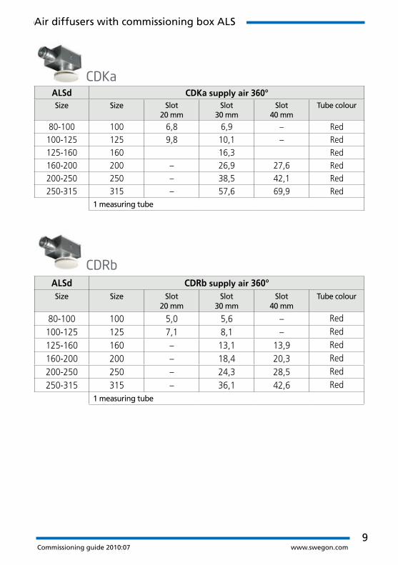
ALSd CDKa supply air 360°Size Size Slot
20 mmSlot
30 mmSlot
40 mmTube colour
80-100 100 6,8 6,9 – Red100-125 125 9,8 10,1 – Red125-160 160 16,3 Red160-200 200 – 26,9 27,6 Red200-250 250 – 38,5 42,1 Red250-315 315 – 57,6 69,9 Red
1 measuring tube
CDKa
ALSd CDRb supply air 360°Size Size Slot
20 mmSlot
30 mmSlot
40 mmTube colour
80-100 100 5,0 5,6 – Red
100-125 125 7,1 8,1 – Red
125-160 160 – 13,1 13,9 Red
160-200 200 – 18,4 20,3 Red
200-250 250 – 24,3 28,5 Red
250-315 315 – 36,1 42,6 Red1 measuring tube
CDRb
Air diffusers with commissioning box ALS

10Commissioning guide 2010:07 www.swegon.com
Innehåll
ALSd CKPa supply air 360°Size Size Slot 20 mm Slot 30 mm Slot 40 mm Tube colour
80-100 100 3,8 6,8 – Red100-125 125 9,9 10,1 – Red125-160 160 – 16,2 16,5 Red160-200 200 – 27,3 27,9 Red200-250 250 – 39,8 42,2 Red250-315 315 – 60,6 68,7 Red
1 measuring tube
CKPa
ALSd CKDa supply airSize Size Diffused Concentrated Tube colour
160-200 200 13,9 12,6 Red200-250 250 22,8 21,1 Red250-315 315 34,7 32,3 Red315-400 400 55,8 52,9 Red
1 measuring tube
CKDa
Air diffusers with commissioning box ALS

11Commissioning guide 2010:07 www.swegon.com
ALSd CVHb supply air 360°Size Size Horizontal Vertical Tube colour
100-125 125 8,9 8,3 Red125-160 160 13,5 11,8 Red160-200 200 22,3 16,8 Red200-250 250 33,9 24,3 Red250-315 315 52,4 37,7 Red315-400 400 79,8 58,7 Red
1 measuring tube
ALSd DPGaSize Size Supply
airTube colour
100-125 125-0 3,8 Red1 measuring tube
CVHb
EIVa
DPGaALSd EAGLE S/D supply airSize EAGLE S EAGLE D Tube
colour
100-125 7,5 8,1 Red125-160 12,1 13,5 Red160-200 20,1 22,2 Red200-250 29,8 33,5 Red250-315 42,3 50,4 Red315-400 67,8 79,6 Red
1 measuring tube
EAGLE S/D a
ALSc EIVaSize Size Supply air Tube colour
80-80 80 4,6 Red80-100 100 5,9 Red100-125 125 8,2 Red125-160 160 10,3 Red
1 measuring tube
Air diffusers with commissioning box ALS
ALSd EIVaSize Size Supply air Tube colour
80-80 80 4,6 Red80-100 100 5,9 Red100-125 125 8,2 Red125-160 160 10,3 Red
1 measuring tube
12Commissioning guide 2010:07 www.swegon.com
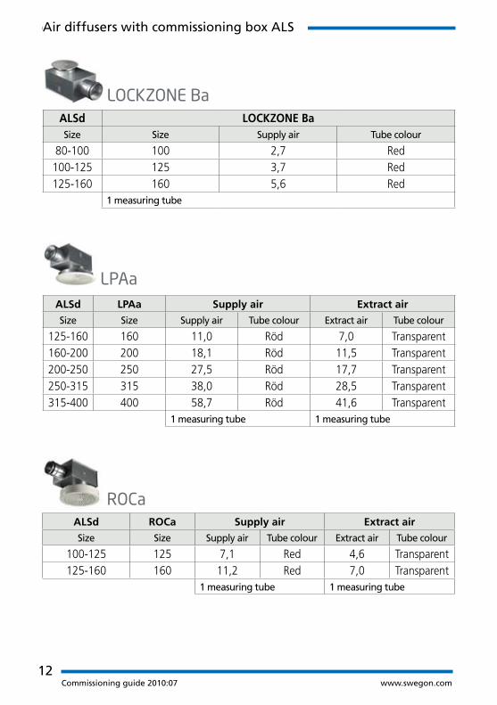
ALSd LPAa Supply air Extract air
Size Size Supply air Tube colour Extract air Tube colour
125-160 160 11,0 Röd 7,0 Transparent160-200 200 18,1 Röd 11,5 Transparent200-250 250 27,5 Röd 17,7 Transparent250-315 315 38,0 Röd 28,5 Transparent315-400 400 58,7 Röd 41,6 Transparent
1 measuring tube 1 measuring tube
LPAa
ALSd LOCKZONE BaSize Size Supply air Tube colour
80-100 100 2,7 Red100-125 125 3,7 Red125-160 160 5,6 Red
1 measuring tube
LOCKZONE Ba
ALSd ROCa Supply air Extract air
Size Size Supply air Tube colour Extract air Tube colour
100-125 125 7,1 Red 4,6 Transparent125-160 160 11,2 Red 7,0 Transparent
1 measuring tube 1 measuring tube
ROCa
Air diffusers with commissioning box ALS

13Commissioning guide 2010:07 www.swegon.com
ALSd COLIBRI CCa supply air
Size Size Standard Low version Tube colour
100-125 125-400 7,3 7,0 Red
100-125 125-600 7,3 7,0 Red100-160 160-400 9,3 8,9 Blue100-160 160-600 9,3 8,9 Blue125-160 160-400 9,8 9,3 Red125-160 160-600 9,8 9,3 Red125-200 200-500 15,6 14,5 Blue125-200 200-600 15,6 14,5 Blue160-200 200-500 16,8 15,2 Red160-200 200-600 16,8 15,0 Red160-250 250-600 23,4 21,7 Blue200-250 250-600 24,9 22,8 Red200-315 315-600 26,4 25,4 Blue250-315 315-600 27,4 25,6 Red315-400 400-600 32,5 – Red
1 measuring tube
ALSd COLIBRI CCa extract air
Size Size Standard Tube colour
200-250 250-600 14,4 Transparent250-315 315-600 18,7 Transparent315-400 400-600 25,5 Transparent
1 measuring tube
COLIBRI CCa
ALSd ROCa Supply air Extract air
Size Size Supply air Tube colour Extract air Tube colour
100-125 125 7,1 Red 4,6 Transparent125-160 160 11,2 Red 7,0 Transparent
1 measuring tube 1 measuring tube
Air diffusers with commissioning box ALS

14Commissioning guide 2010:07 www.swegon.com
Innehåll
ALSd COLIBRI CRa supply air
Size Size Standard Low version Tube colour
100-125 125-400 7,4 7,2 Red100-125 125-600 7,4 7,2 Red100-160 160-400 9,5 9,2 Blue100-160 160-600 9,5 9,2 Blue125-160 160-400 10,0 9,6 Red125-160 160-600 10,0 9,6 Red125-200 200-500 16,7 15,5 Blue125-200 200-600 16,7 15,5 Blue160-200 200-500 17,7 16,5 Red160-200 200-600 17,7 16,5 Red160-250 250-600 26,4 24,7 Blue200-250 250-600 28,9 26,4 Red200-315 315-600 30,3 28,6 Blue250-315 315-600 32,1 29,5 Red315-400 400-600 37,7 – Red
1 measuring tube
ALSd COLIBRI CRa extract air
Size Size Standard Tube colour
200-250 250-600 16,2 Transparent250-315 315-600 21,2 Transparent315-400 400-600 29,1 Transparent
1 measuring tube
COLIBRI CRa
Air diffusers with commissioning box ALS
15Commissioning guide 2010:07 www.swegon.com
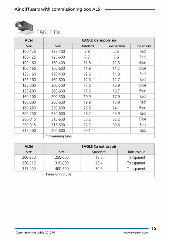
ALSd EAGLE Ca supply air
Size Size Standard Low version Tube colour
100-125 125-400 7,8 7,6 Red
100-125 125-600 7,7 7,6 Red
100-160 160-400 11,8 11,5 Blue
100-160 160-600 11,8 11,2 Blue
125-160 160-400 12,6 11,9 Red
125-160 160-600 12,6 11,7 Red
125-200 200-500 17,6 16,9 Blue
125-200 200-600 17,6 16,7 Blue
160-200 200-500 19,9 17,9 Red
160-200 200-600 19,9 17,9 Red
160-250 250-600 26,5 24,1 Blue
200-250 250-600 28,2 25,9 Red
200-315 315-600 35,2 32,2 Blue
250-315 315-600 37,3 33,5 Red
315-400 400-600 53,1 – Red1 measuring tube
ALSd EAGLE Ca extract air
Size Size Standard Tube colour
200-250 250-600 18,6 Transparent250-315 315-600 26,4 Transparent315-400 400-600 39,6 Transparent
1 measuring tube
EAGLE Ca
Air diffusers with commissioning box ALS

16Commissioning guide 2010:07 www.swegon.com
ALSd HAWK Ca supply air
Size Size Standard Low version Tube colour
100-125 125-600 8,4 8,0 Red100-160 160-600 11,7 10,9 Blue125-160 160-600 12,3 11,9 Red125-200 200-600 19,1 17,0 Blue160-200 200-600 20,9 18,2 Red160-250 250-600 29,1 25,7 Blue200-250 250-600 32,5 28,5 Red
200-315 315-600 37,0 34,2 Blue250-315 315-600 39,4 35,3 Red315-400 400-600 50,9 - Red
1 measuring tube
ALSd HAWK Ca extract air
Size Size Standard Tube colour
200-250 250-600 19,1 Transparent250-315 315-600 25,4 Transparent315-400 400-600 34,9 Transparent
1 measuring tube
HAWK Ca
Air diffusers with commissioning box ALS
17Commissioning guide 2010:07 www.swegon.com
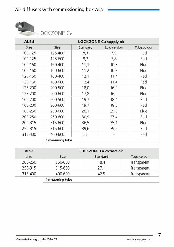
ALSd LOCKZONE Ca supply air
Size Size Standard Low version Tube colour
100-125 125-400 8,3 7,9 Red100-125 125-600 8,2 7,8 Red100-160 160-400 11,1 10,8 Blue100-160 160-600 11,2 10,8 Blue125-160 160-400 12,1 11,4 Red125-160 160-600 12,4 11,4 Red125-200 200-500 18,0 16,9 Blue125-200 200-600 17,8 16,9 Blue160-200 200-500 19,7 18,4 Red160-200 200-600 19,7 18,0 Red160-250 250-600 28,1 25,6 Blue200-250 250-600 30,9 27,4 Red200-315 315-600 36,5 35,1 Blue250-315 315-600 39,6 39,6 Red315-400 400-600 56 – Red
1 measuring tube
ALSd LOCKZONE Ca extract air
Size Size Standard Tube colour
200-250 250-600 18,4 Transparent250-315 315-600 27,1 Transparent315-400 400-600 42,5 Transparent
1 measuring tube
LOCKZONE Ca
Air diffusers with commissioning box ALS

18Commissioning guide 2010:07 www.swegon.com
ALSd PELICAN CSa supply air
Size Size Standard Low version Tube colour
100-125 125-400 7,1 7,7 Red + Red100-160 160-400 10,6 10,1 Blue + Red125-160 160-400 11,4 11,8 Red + Red125-200 200-600 16,0 16,5 Blue + Red160-200 200-600 18,1 19,0 Red + Red160-250 250-600 25,7 27,1 Blue + Red200-250 250-600 29,0 28,4 Red + Red200-315 315-600 37,6 36,1 Blue + Red250-315 315-600 44,0 38,1 Red + Red315-400 400-600 68,2 – Red
2 measuring tubes, NOTE! size 400-600 1 measuring tube
ALSd PELICAN CEa extract air
Size Size Standard Low version Tube colour
100-125 125-400 4,9 4,6 Transparent125-160 160-400 7,6 7,2 Transparent160-200 200-600 14,2 12,6 Transparent200-250 250-600 21,2 20,2 Transparent250-315 315-600 27,9 27,7 Transparent315-400 400-600 41,6 – Transparent
1 measuring tube
PELICAN CSa
PELICAN CEa
Air diffusers with commissioning box ALS

19Commissioning guide 2010:07 www.swegon.com
Air diffusers with commissioning box ALV
Figure 1. Measurement with one tube. Figure 2. Measurement with one tube.
ALVd COLIBRI Wall supply air
Back side connection Short side connection
Size Size Closed slot Open slot Closed slot Open slot
300-150-100 300-150 5,4 7,1 5,1 6,6
400-150-125 400-150 7,8 9,9 7,6 9,4
400-200-160 400-200 10,2 12,7 10,1 12,4
550-250-200 550-250 16,9 20,5 16,5 20
550-300-250 550-300 19,8 23,7 19,6 23,5
ALVd EAGLE Wall supply air
Back side connection Short side connection
Size Size Closed slot Open slot Closed slot Open slot
300-150-100 300-100 7,8 9,2 7,2 8,1
400-150-125 400-150 9,9 11,8 9,6 11,1
400-200-160 400-200 14,8 17,1 14 15,9
550-250-200 550-250 25,5 27,8 24,4 26,8
550-300-250 550-300 31,1 33,9 30,5 33,4
COLIBRI Wa
EAGLE Wa

20Commissioning guide 2010:07 www.swegon.com
Air diffusers with commissioning box ALV
ALVd LOCKZONE Wall supply air
Size Back side connection Short side connection
300-150 7,4 6,9400-150 10 9,9400-200 15 14,3550-250 26,3 24,9550-300 32,4 32
LOCKZONE Wa
ROWbALVd ROWb supply air
Size Back side connection Short side connection
400-150-125-B 400-150 10,0400-200-160-B 400-200 15,0
PELICAN WaALVd PELICAN Wall supply air
Size Size Back side connection Short side connection
300-150-100 300-100 8,8 8,1
400-150-125 400-150 10,9 11,1
400-200-160 400-200 17,3 17,3
550-250-200 550-250 25,6 25,1
550-300-250 550-300 32,2 32,6

21Commissioning guide 2010:07 www.swegon.com
Air diffusers with commissioning box TRG
TRGc ALGc supply air ALGc extract air
Connection Connection
Size B K L B K L
200-100-125 7,2 7,1 7,4 7,6 7,7 7,2300-100-160 11,9 12,2 12,3 13,4 13,0 12,3400-100-160 15,9 16,2 15,5 19,3 18,2 17,4500-100-200 21,4 21,4 22,2 23,2 23,0 21,2300-150-200 19,6 19,4 20,2 20,9 21,4 19,2400-150-250 26,9 26,3 27,3 28,9 28,2 26,4500-150-250 35,0 34,5 32,4 36,3 35,7 33,3400-200-250 36,8 38,5 42,0 45,6 44,3 41,0500-200-315 52,4 50,8 48,5 56,3 56,1 51,5600-200-315 61,9 60,7 57,6 70,7 69,6 61,0
2 measuring tubes. Connection alternatives B= Back side, K = Short side, L = Long side
ALGc
Figure 1. Measurement with two tubes.

22Commissioning guide 2010:07 www.swegon.com
TRGc GRLc extract air
Connection
Storlek B = back side K = short side L = long side
200-100-125 7,9 8,5 7,0300-100-160 13,3 13,2 11,8400-100-160 18,9 18,5 16,9500-100-200 23,2 23,3 21,0300-150-200 21,0 20,9 18,5400-150-250 29,1 28,4 25,3500-150-250 36,6 35,7 32,4400-200-250 46,6 42,9 39,8500-200-315 56,8 55,4 47,9600-200-315 70,0 68,5 59,4600-300-400 109,0 107,0 104,0
2 measuring tubes
TRGc GTHc supply air, straight blades GTHc supply air, blades 45°
Connection Connection
Size B K L B K L
200-100-125 7,5 7,2 7,3 7,2 7,0 7,1300-100-160 12,1 12,1 12,3 11,3 11,9 12,1400-100-160 16,2 16,6 15,4 15,0 16,1 15,0500-100-200 21,1 20,7 22,1 20,1 20,4 21,1300-150-200 19,3 19,2 19,7 19,4 18,8 19,2400-150-250 26,5 26,1 27,9 25,4 25,8 26,6500-150-250 34,8 33,5 32,9 33,8 33,4 30,9400-200-250 38,1 39,2 41,2 37,4 38,1 41,1500-200-315 50,5 48,4 48,3 48,0 48,2 46,4600-200-315 60,3 58,7 56,6 57,6 57,8 54,4
2 measuring tubes Connection alternatives: B = Back side, K = Short side, L = Long side
GRLc
GTHc
Air diffusers with commissioning box ALV

23Commissioning guide 2010:07 www.swegon.com
Air diffusers with circular commissioning box
Figure 1. Measurement with two tubes. Figure 2. Measurement with two tubes.
Straight sections are required before the diffuser to secure that the stated method errors, 5 %, will be obtained, see table:
1 · 90° bend 3 · Ød
2 · 90° bend 4 · Ød
T-joint 4 · Ød
Damper 45° 6 · Ød
ACDa supply air
Size Slot 20 mm Slot 30 mm Slot 40 mm
100 5,5 5,5 –125 8,9 8,9 –160 – 15,5 15,5200 – 25,8 25,8250 – 39,6 39,6315 – 67,4 67,4
2 measuring tubes. Spread pattern: 360°
ACDa

24Commissioning guide 2010:07 www.swegon.com
Air diffusers with circular commissioning box
EAGLE Fb supply air EAGLE Fb extract air
Size k-factor Tube colour K-factor Tube colour
100 5,2 Blue + transparent 7,0 Transparent125 8,2 Blue + transparent 11,4 Transparent160 14,8 Blue + transparent 16,6 Transparent200 24,5 Blue + transparent 26,0 Transparent250 36,9 Blue + transparent 36,0 Transparent315 62,6 Blue + transparent 46,0 Transparent400 101,0 Blue + transparent 74,0 Transparent
2 measuring tubes 1 measuring tube
LOCKZONE Fa supply air
Size Slot 20 mm Slot 30 mm
125 14,1 15,2
160 23,4 25,7
200 35,1 38,6
250 51,5 56,7
315 74,5 83,1
1 measuring tube Spread pattern: 360° No straight section required.
EAGLE Fb
LOCKZONE Fa

25Commissioning guide 2010:07 www.swegon.com
Displacement units
Figure 1. DBC, DHC, DVC. Measurement with one tube.
Figur 2. DCP. Measurement with one tube.
DBCa DBRe
Size Supply air Supply air
200 34,0 36,8250 54,0 41,0315 89,5 46,5400 142,5 –
200-600 122,0 –300-600 185,0 –
1 measuring tube.
DBCa DBRe

26Commissioning guide 2010:07 www.swegon.com
Displacement units
DCPe DHCe DVCe
Size Supply air Supply air Supply air
125 12,2 12,0 12,0160 22,8 20,0 20,0200 37,0 33,0 33,0250 58,0 50,0 50,0315 88,0 84,0 84,0400 141,0 134,0 134,0500 210,0 202,0 –630 295,0 285,0 –800 – 520,0 –
1 measuring tube
ICPa IHCa IVCa
Size Supply air Supply air Supply air
200 22,9 22,9 22,9250 35,9 35,9 35,9315 54,4 54,4 54,4
1 measuring tube
DCPe DHCe DVCe
ICPa IHCa IVCa

27Commissioning guide 2010:07 www.swegon.com
ICPa IHCa IVCa
Size Supply air Supply air Supply air
200 22,9 22,9 22,9250 35,9 35,9 35,9315 54,4 54,4 54,4
1 measuring tube
Displacement units
Figure 3. DIR. Measurement with one tube. Figure 4. DRC and DKC. Measurement with one tube.
Figure 5. DRI. Measurement with one tube.
DIRc DKCe DRCe DRIf
Size Supply air Supply air Supply air Supply air
400-100 13,1 – – –500-125 18,7 – – –600-160 23,5 – – –900-200 46,8 – – –
200 – – 32,0 32,0250 – – 53,0 53,0315 – – 85,0 85,0400 – – 130,0 130,0
200-600 – – 120,0 120,0250-800 – – 176,0 176,0
500 – 133,0 – –630 – 223,0 – –800 – 350,0 – –
1 measuring tube
DIRc DKCe DRCe DRIf

28Commissioning guide 2010:07 www.swegon.com
Home air diffuser/Duct disc diffuser with adjustable measuring unit
Adjustable measuring unit IBIS Ca
Size k-factor
160-1500 14,8
200-1500 22,5
250-1500 36,1
315-1500 61,2
400-1500 96
2 measuring tubes
DOMO b
Adjustment k-factor
R 1 1,3
R 2 2,3
R 3 3,3
R 4 3,9
DOMO b
IBIS Ca

29Commissioning guide 2010:07 www.swegon.com
Slot diffusers
SLAT1 SLAa supply air
Size 90° 0°
2-600 7,1 7,94-600 14,8 17,56-600 22,0 27,52-900 10,6 12,54-900 21,2 25,36-900 29,4 35,4
1 measuring tube
SLAT2 SLAa supply air
Size 90° 0°
2-600 7,5 9,24-600 15,0 18,46-600 22,5 27,62-900 11,0 13,84-900 22,0 27,66-900 33,0 41,4
1 measuring tube
SLAa
SLAa

30Commissioning guide 2010:07 www.swegon.com
Linear disc diffuser with commissioning box
SRYT 1b SRYb
Size Size Supply air Size Supply air
1-500-125-L 1-900-1 4,5 1-1200-1 5,32-500-160-L 2-900-1 8,6 2-1200-2 6,53-500-160-L 3-900-1 12,4 3-1200-2 9,44-500-200-L 4-900-1 16,2 4-1200-2 12,4
1 measuring tube Note! The K-factor is valid for one commissioning box. Ex: With two or three commissioning boxes for one diffuser, the total of the designed airflow shall be divided by the number of commissioning boxes.
SRYT 2b SRYb
Size Size Supply air Size Supply air
1-500-125-L 1-1500-2 4,2 1-1800-2 4,62-500-160-L 2-1500-2 7,8 2-1800-2 8,63-500-160-L 3-1500-2 11,4 3-1800-2 13,04-500-200-L 4-1500-2 14,4 4-1800-3 12,4
1 measuring tube Note! The K-factor is valid for one commissioning box. Ex: With two or three commissioning boxes for one diffuser, the total of the designed airflow shall be divided by the number of commissioning boxes.
SRYb
SRYb

31Commissioning guide 2010:07 www.swegon.com
Extract air diffusers
��
Figure 1. EXC and ROE. Measurement with one tube.
EXCa 100 EXCa 125 EXCa 160 EXCa 200
Cone position k-factor k-factor k-factor k-factor
-15 0,6 – – –-12 0,8 – – –-10 1,0 1,3 2,0 –-5 1,4 1,9 2,8 –-3 – – – 1,80 1,8 2,6 3,6 2,6
+5 2,3 3,2 4,5 3,8+10 2,7 3,9 5,4 5,2+15 – – 6,2 6,4+20 – – – 7,5+25 – – – 8,6
Measured by pressure gauge.
EXCa

32Commissioning guide 2010:07 www.swegon.com
Extract air diffusers
ROEa 100 ROEa 125 ROEa 160 ROEa 200
Cone position k-factor k-factor k-factor k-factor
-15 0,6 – – –-12 0,8 – – –-10 1,0 1,3 2,0 –-5 1,4 1,9 2,8 –-3 – – – 1,80 1,8 2,6 3,6 2,6
+5 2,3 3,2 4,5 3,8+10 2,7 3,9 5,4 5,2+15 – – 6,2 6,4+20 – – – 7,5+25 – – – 8,6
Measured by pressure gauge
ROEa

33Commissioning guide 2010:07 www.swegon.com
Dampers and measuring products
Flow control
Figure 1. Number of measuring tubes: 2. Connected to ”nipple well”. The K-factor is also valid for the combination VAR with sound attenuator CLA L=500 or 1000mm.
Size VARd 1, 2, 4
100 5,8125 9,2160 15,6200 25,4250 39,9315 63,6400 104500 165
Straight sections are required before the damper to secure that stated method er-rors, 5%, will be obtained, see table:
1 · 90° bend 3 · Ød
2 · 90° bends 4 · Ød
1 · T-joint 4 · Ød
Mixing box 4 · Ød
VARd circular

34Commissioning guide 2010:07 www.swegon.com
Dampers and measuring products
Size VARd
200-200 33,5300-200 50,0400-200 66,5500-200 83,5600-200 100,0700-200 117,0800-200 133,01000-200 167,0400-300 102,0500-300 127,0600-300 152,0700-300 178,0800-300 203,0850-300 216,01000-300 254,0400-400 136,0500-400 171,0600-400 205,0700-400 239,0800-400 273,01000-400 341,01200-400 409,01400-400 478,01600-400 546,0
Size VARd
500-500 214,0600-500 257,0800-500 343,01000-500 429,01200-500 514,01400-500 600,01600-500 686,0600-600 309,0800-600 412,01000-600 515,01200-600 618,01400-600 722,01600-600 825,0700-700 422,0800-700 482,01000-700 603,01200-700 723,01400-700 844,01600-700 964,0
VARd rectangular

35Commissioning guide 2010:07 www.swegon.com
Dampers and measuring products
IRIS a, k-factor
Size 1 1,5 2 2,5 3 3,5 4 4,5
80 6,1 – 4,1 – 3,2 – 2,3 –100 10,4 7,9 7,5 6,6 6,0 5,2 4,5 3,8125 13,8 10,4 8,8 7,3 6,5 5,5 4,7 4,0150 24,1 20,0 16,5 14,9 13,4 12,0 11,0 10,0160 22,1 17,2 14,8 13,4 12,5 11,5 10,7 9,5200 44,2 36,6 30,9 26,9 23,2 20,6 18,2 15,9250 64,4 53,5 45,6 41,8 38,7 34,5 30,7 27,3315 118,0 88,3 70,0 64,5 58,7 53,0 45,1 42,4400 131,0 – 102,0 – 88,3 – 67,3 –500 230,0 – 177,0 – 146,0 – 112,0 –630 451,0 – 297,0 – 238,0 – 169,0 –800 489,0 – 402,0 – 344,0 – 267,0 –
IRIS a, k-factor
Size 5 5,5 6 6,5 7 7,5 8
80 1,4 – 0,9 – 0,6 – –100 3,4 2,9 2,5 2,1 1,7 1,2 0,9125 3,5 3,1 2,7 2,2 1,5 – –150 8,9 7,9 6,9 6,0 5,2 4,4 3,7160 8,5 7,5 6,8 5,6 4,9 4,0 3,5200 14,0 12,3 11,0 9,6 8,4 6,5 5,0250 24,1 21,4 18,4 15,8 12,8 10,9 8,9315 37,0 33,3 30,0 25,9 21,8 19,0 15,8400 52,7 – 38,5 – 28,4 – 15,5500 88,5 – 66,6 – 48,0 – 30,0630 127,0 – 91,6 – 62,8 – 35,1800 217,0 – 170,0 – 122,0 – 73,7
IRISa

36Commissioning guide 2010:07 www.swegon.com
Dampers and measuring products
Straight sections are required before the damper to secure that the stated method errors, 5%, will be obtained, see table:
Figure 2. Measurement with two tubes.
1 · 90° bend 3 · Ød
2 · 90° bends 4 · Ød
T-joints 4 · Ød
Damper 45° 6 · Ød
Size CRMc 1 CRMc 5
80 5,0100 9,2 9,2125 9,6 9,6160 15,8 15,8200 23,5 23,5250 35,6 35,6315 59,2 59,2400 95,6 95,6500 147,0 –630 230,0 –
2 measuring tubes
CRMc 1 CRMc 5

37Commissioning guide 2010:07 www.swegon.com
Climate systems
Calculation formula
q = primary air fl ow in l/s p = balancing pressure in Pa k = the pressure constant (k-factor) of the unit The pressure constant is valid by 20°C and 1013 mbar
Measuring point
All climate beams and comfort modules are equipped with a tube where the nozzle pres-sure can be measured. When commissioning connect a manometer to the tube (inside diameter: 4 mm).
The positioning of the tube depends on the type of product. For beams with only one primary air connection the tube is placed close to the opposite end of the unit seen from the connection side. For beams with alternative primary air connections the tube is placed in the centre of the beam. For comfort modules the tube is placed in one of the corners.
q = k · √ pi
(l/s)
Nozzle configuration 1 – 4
(Same distance between the nozzles on both sides of the unit)
Nozzle configuration E, N, and 75/25%
(Different distance between the nozzles on the right and the left side of the unit)
C-C distance between nozzles
Nozzle configuration C–C (mm)
1 302 403 604 15E 30/90N 12/36
Climate systems

38Commissioning guide 2010:07 www.swegon.com
Climate beams and comfort modules
BALTIC / BRC
Nozzle configuration
Length 1 2 3 4 E N
1,2 2 1,5 1 4,1 1,4 3,41,5 2,6 1,9 1,3 5,2 1,7 4,31,8 3,1 2,4 1,6 6,3 2,1 5,22,1 3,7 2,8 1,9 7,4 2,5 6,22,4 4,3 3,2 2,1 8,5 2,8 7,12,7 4,8 3,6 2,4 9,7 3,2 83 5,4 4 2,7 10,8 3,6 9
3,3 5,9 4,5 3 11,9 4 9,93,6 6,5 4,9 3,3 13 4,3 10,83,9 7,1 5,3 3,5 14,1 4,7 11,8
Adjustable nozzles: Addition of 0.15 per adjustable nozzle E.G: BALTIC a 2.4-4-N4x5 Pressure constant= 8.5+ (20x0.15)= 11.5
BALTIC/BRC

39Commissioning guide 2010:07 www.swegon.com
Climate beams and comfort modules
BISCAYNozzle configuration
Length 60/60 48/48 36/36 24/24 12/12 24/72, 72/24 12/36, 36/12
1092 0,92 1,16 1,54 2,31 4,62 1,54 3,081192 1,02 1,27 1,7 2,54 5,09 1,7 3,391242 1,06 1,33 1,77 2,66 5,32 1,77 3,551342 1,16 1,45 1,93 2,89 5,79 1,93 3,861392 1,2 1,51 2,01 3,01 6,02 2,01 4,011492 1,3 1,62 2,16 3,24 6,49 2,16 4,321692 1,48 1,86 2,47 3,71 7,42 2,47 4,951792 1,58 1,97 2,63 3,94 7,89 2,63 5,261867 1,65 2,06 2,75 4,12 8,24 2,75 5,492017 1,79 2,23 2,98 4,49 8,94 2,98 5,962092 1,86 2,32 3,1 4,64 9,29 3,1 6,192392 2,14 2,67 3,56 5,34 10,69 3,54 7,122492 2,23 2,79 3,72 5,58 11,15 3,72 7,442692 2,42 3,02 4,03 6,04 12,09 4,03 8,062992 2,7 3,37 4,5 6,74 13,49 4,5 8,99
BISCAY

40Commissioning guide 2010:07 www.swegon.com
BSAd
Nozzle
Length 1 2 3 E
1,2 2 1,5 1 1,41,5 2,6 1,9 1,3 1,71,8 3,1 2,4 1,6 2,12,1 3,7 2,8 1,9 2,52,4 4,3 3,2 2,1 2,82,7 4,8 3,6 2,4 3,23 5,4 4 2,7 3,6
3,3 5,9 4,5 3 43,6 6,5 4,9 3,3 4,33,9 7,1 5,3 3,5 4,7
BSAd
Climate beams and comfort modules

41Commissioning guide 2010:07 www.swegon.com
PARASOL 592 MF Nozzle configura-
tion per side Nozzle size kpl per side
L Small 0,253M Large 0,440H Small +
Large0,693
C Closed 0
Figure 1. Top view of nozzle configuration, single-module unit, sides 1-4.
Figure 2. Example of nozzle configuration for a single-module unit - LLMM.
PARASOL 592 MFNozzle configuration* kpl
LLLL 1,01LLMM 1,39
MMMM 1,76MMHH 2,27HHHH 2,77
* All four sides of the unit can be adjusted individually. The description of the nozzle setting follows the order shown in figure 5. See example shown in figure 6.
PARASOL 592
Climate beams and comfort modules

42Commissioning guide 2010:07 www.swegon.com
PARASOL 1192 LFNozzle
configuration*kpl Nozzle configura-
tion per sideSide Nozzle
configurationkpl per side
LLLL 0,9 L Short side Small 0,124LLMM 1,09 L Long side Small 0,328
MMMM 1,28 M Short side Large 0,176MMHH 1,73 M Long side Large 0,464HHHH 2,18 H Short side Small + Large 0,3
H Long side Small + Large 0,792C Short side Closed 0C Long side Closed 0
* All four sides of the unit can be adjusted individually. The description of the nozzle setting follows the order shown in figure 3. See example shown in figure 2, p 43.
PARASOL 1192 MFNozzle
configuration*kpl Nozzle configura-
tion per sideSide Nozzle
configurationkpl per side
LLLL 1,28 L Short side Small 0,176LLMM 1,56 L Long side Small 0,464
MMMM 1,84 M Short side Large 0,253MMHH 2,48 M Long side Large 0,667HHHH 3,12 H Short side Small + Large 0,429
H Long side Small + Large 1,131C Short side Closed 0C Long side Closed 0
* All four sides of the unit can be adjusted individually. The description of the nozzle setting follows the order shown in figure 3. See example shown in figure 2, p 43.
PARASOL 1192
Climate beams and comfort modules

43Commissioning guide 2010:07 www.swegon.com
Figure 3. Top view nozzle configuration double-module unit, sides 1-4.
Figure 4. Example of nozzle configuration for a double-mounted unit - MLHM.
PARASOL 1192 HFNozzle
configuration*kpl Nozzle configuration
per sideSide Nozzle
configurationkpl per side
LLLL 1,84 L Short side Small 0,253LLMM 2,52 L Long side Small 0,667
MMMM 3,2 M Short side Large 0,44MMHH 4,12 M Long side Large 1,16HHHH 5,04 H Short side Small + Large 0,693
H Long side Small + Large 1,827C Short side Closed 0C Long side Closed 0
* All four sides of the unit can be adjusted individually. The description of the nozzle setting follows the order shown in figure 3. See example shown in figure 2, p 43.
Climate beams and comfort modules

44Commissioning guide 2010:07 www.swegon.com
PARASOL EX 690 MFNozzle configuration* kpl
LLLL 1,01LLMM 1,39
MMMM 1,76MMHH 2,27HHHH 2,77
* All four sides of the unit can be adjusted individually. The description of the nozzle setting follows the order shown in figure 1. See example shown in figure 2.
PARASOL EX 690 MFNozzle configura-
tion per sideNozzle side kpl per
side
L Small 0,253M Large 0,44H Small+Large 0,693C Closed 0
Figure 1. Top view of nozzle setting single-module unit, sides 1-4.
Figure 2. Example of nozzle setting for a single-module unit - LLMM.
PARASOL EX 690
Climate beams and comfort modules

45Commissioning guide 2010:07 www.swegon.com
PARASOL EX 1290 MFNozzle
configuration*kpl Nozzle configuration
per sideSide Nozzle
configurationkpl per side
LLLL 1,28 L Short side Small 0,176LLMM 1,56 L Long side Small 0,464
MMMM 1,84 M Short side Large 0,253MMHH 2,48 M Long side Large 0,667HHHH 3,12 H Short side Small+Large 0,429
H Long side Small+Large 1,131C Short side Closed 0C Long side Closed 0
* All four sides of the unit can be adjusted individually. The description of the nozzle setting follows the order shown in figure 7. See example shown in figure 8.
PARASOL EX 1290 HFNozzle
configuration*kpl Nozzle configuration
per sideSide Nozzle
configurationkpl per side
LLLL 1,84 L Short side Small 0,253LLMM 2,52 L Long side Small 0,667
MMMM 3,2 M Short side Large 0,44MMHH 4,12 M Long side Large 1,16HHHH 5,04 H Short side Small+Large 0,693
H Long side Small+Large 1,827C Short side Closed 0C Long side Closed 0
* All four sides of the unit can be adjusted individually. The description of the nozzle setting follows the order shown in figure 7. See example shown in figure 8.
Figure 7. Top view nozzle setting, double- module unit sides 1-4.
Figure 8. Example of nozzle setting for a double-module unit - MLHM.
PARASOL EX 1290
Climate beams and comfort modules

46Commissioning guide 2010:07 www.swegon.com
Room 203 ADRIATIC 1,8
22 l/s
ADRIATIC 1,8
q=17,5-26,5 (l/s)
k=3,19 q50%=>2LH q50%=>2LH
1. 2.
L
H
H
L
L
L3,19
4.3.
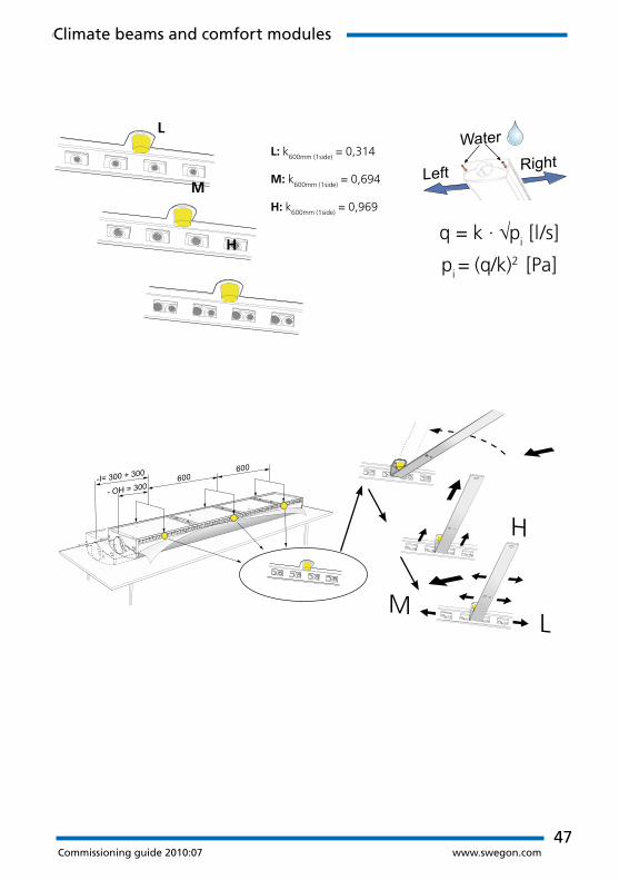
ADRIATIC VF
Climate beams and comfort modules
47Commissioning guide 2010:07 www.swegon.com
-I= 300 + 300
- OH = 300600
600
q = k · √pi [l/s]
pi = (q/k)2 [Pa]
L: k600mm (1side)
= 0,314
M: k600mm (1side)
= 0,694
H: k600mm (1side)
= 0,969
L
M
H
Climate beams and comfort modules
48Commissioning guide 2010:07 www.swegon.com
Climate beams and comfort modules
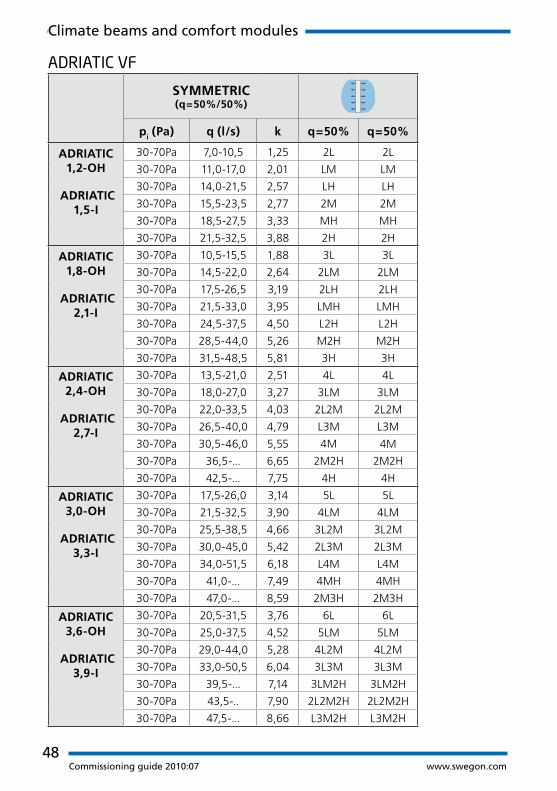
ADRIATIC VF
SYMMETRIC (q=50%/50%)
ASYMMETRIC
(q≈70%/30%)
pi (Pa) q (l/s) k q=50% q=50% pi (Pa) q (l/s) k q≈70% q≈30%
ADRIATIC 1,2-OH
ADRIATIC 1,5-I
30-70Pa 7,0-10,5 1,25 2L 2L ADRIATIC 1,2-OH
ADRIATIC 1,5-I
30-70Pa 11,0-17,0 2,01 2M 2L
30-70Pa 11,0-17,0 2,01 LM LM 30-70Pa 14,0-21,5 2,57 2H 2L
30-70Pa 14,0-21,5 2,57 LH LH 30-70Pa 16,0-24,5 2,95 2H LM
30-70Pa 15,5-23,5 2,77 2M 2M
30-70Pa 18,5-27,5 3,33 MH MH
30-70Pa 21,5-32,5 3,88 2H 2H
ADRIATIC 1,8-OH
ADRIATIC 2,1-I
30-70Pa 10,5-15,5 1,88 3L 3L ADRIATIC 1,8-OH
ADRIATIC 2,1-I
30-70Pa 14,5-22,0 2,64 L2M 3L
30-70Pa 14,5-22,0 2,64 2LM 2LM 30-70Pa 19,5-30,0 3,57 M2H 3L
30-70Pa 17,5-26,5 3,19 2LH 2LH 30-70Pa 21,0-32,0 3,85 3H 3L
30-70Pa 21,5-33,0 3,95 LMH LMH 30-70Pa 23,0-35,5 4,23 3H 2LM
30-70Pa 24,5-37,5 4,50 L2H L2H 30-70Pa 25,5-38,5 4,61 3H L2M
30-70Pa 28,5-44,0 5,26 M2H M2H
30-70Pa 31,5-48,5 5,81 3H 3H
ADRIATIC 2,4-OH
ADRIATIC 2,7-I
30-70Pa 13,5-21,0 2,51 4L 4L ADRIATIC 2,4-OH
ADRIATIC 2,7-I
30-70Pa 18,0-27,0 3,27 2L2M 4L
30-70Pa 18,0-27,0 3,27 3LM 3LM 30-70Pa 22,0-33,5 4,03 4M 4L
30-70Pa 22,0-33,5 4,03 2L2M 2L2M 30-70Pa 25,0-38,0 4,58 2M2H 4L
30-70Pa 26,5-40,0 4,79 L3M L3M 30-70Pa 28,0-42,5 5,13 4H 4L
30-70Pa 30,5-46,0 5,55 4M 4M 30-70Pa 34,5-52,0 6,27 4H L3M
30-70Pa 36,5-... 6,65 2M2H 2M2H
30-70Pa 42,5-... 7,75 4H 4H
ADRIATIC 3,0-OH
ADRIATIC 3,3-I
30-70Pa 17,5-26,0 3,14 5L 5L ADRIATIC 3,0-OH
ADRIATIC 3,3-I
30-70Pa 25,5-39,0 4,66 L4M 5L
30-70Pa 21,5-32,5 3,90 4LM 4LM 30-70Pa 30,5-46,5 5,59 3M2H 5L
30-70Pa 25,5-38,5 4,66 3L2M 3L2M 30-70Pa 35,5-... 6,41 5H 5L
30-70Pa 30,0-45,0 5,42 2L3M 2L3M 30-70Pa 39,0-... 7,17 5H 3L2M
30-70Pa 34,0-51,5 6,18 L4M L4M
30-70Pa 41,0-... 7,49 4MH 4MH
30-70Pa 47,0-... 8,59 2M3H 2M3H
ADRIATIC 3,6-OH
ADRIATIC 3,9-I
30-70Pa 20,5-31,5 3,76 6L 6L ADRIATIC 3,6-OH
ADRIATIC 3,9-I
30-70Pa 26,5-40,0 4,80 4LMH 6L
30-70Pa 25,0-37,5 4,52 5LM 5LM 30-70Pa 33,0-50,5 6,04 6M 6L
30-70Pa 29,0-44,0 5,28 4L2M 4L2M 30-70Pa 37,5-... 6,87 3M3H 6L
30-70Pa 33,0-50,5 6,04 3L3M 3L3M 30-70Pa 40,5-... 7,42 M5H 6L
30-70Pa 39,5-... 7,14 3LM2H 3LM2H
30-70Pa 43,5-.. 7,90 2L2M2H 2L2M2H
30-70Pa 47,5-... 8,66 L3M2H L3M2H

49Commissioning guide 2010:07 www.swegon.com
Climate beams and comfort modules
SYMMETRIC (q=50%/50%)
ASYMMETRIC
(q≈70%/30%)
pi (Pa) q (l/s) k q=50% q=50% pi (Pa) q (l/s) k q≈70% q≈30%
ADRIATIC 1,2-OH
ADRIATIC 1,5-I
30-70Pa 7,0-10,5 1,25 2L 2L ADRIATIC 1,2-OH
ADRIATIC 1,5-I
30-70Pa 11,0-17,0 2,01 2M 2L
30-70Pa 11,0-17,0 2,01 LM LM 30-70Pa 14,0-21,5 2,57 2H 2L
30-70Pa 14,0-21,5 2,57 LH LH 30-70Pa 16,0-24,5 2,95 2H LM
30-70Pa 15,5-23,5 2,77 2M 2M
30-70Pa 18,5-27,5 3,33 MH MH
30-70Pa 21,5-32,5 3,88 2H 2H
ADRIATIC 1,8-OH
ADRIATIC 2,1-I
30-70Pa 10,5-15,5 1,88 3L 3L ADRIATIC 1,8-OH
ADRIATIC 2,1-I
30-70Pa 14,5-22,0 2,64 L2M 3L
30-70Pa 14,5-22,0 2,64 2LM 2LM 30-70Pa 19,5-30,0 3,57 M2H 3L
30-70Pa 17,5-26,5 3,19 2LH 2LH 30-70Pa 21,0-32,0 3,85 3H 3L
30-70Pa 21,5-33,0 3,95 LMH LMH 30-70Pa 23,0-35,5 4,23 3H 2LM
30-70Pa 24,5-37,5 4,50 L2H L2H 30-70Pa 25,5-38,5 4,61 3H L2M
30-70Pa 28,5-44,0 5,26 M2H M2H
30-70Pa 31,5-48,5 5,81 3H 3H
ADRIATIC 2,4-OH
ADRIATIC 2,7-I
30-70Pa 13,5-21,0 2,51 4L 4L ADRIATIC 2,4-OH
ADRIATIC 2,7-I
30-70Pa 18,0-27,0 3,27 2L2M 4L
30-70Pa 18,0-27,0 3,27 3LM 3LM 30-70Pa 22,0-33,5 4,03 4M 4L
30-70Pa 22,0-33,5 4,03 2L2M 2L2M 30-70Pa 25,0-38,0 4,58 2M2H 4L
30-70Pa 26,5-40,0 4,79 L3M L3M 30-70Pa 28,0-42,5 5,13 4H 4L
30-70Pa 30,5-46,0 5,55 4M 4M 30-70Pa 34,5-52,0 6,27 4H L3M
30-70Pa 36,5-... 6,65 2M2H 2M2H
30-70Pa 42,5-... 7,75 4H 4H
ADRIATIC 3,0-OH
ADRIATIC 3,3-I
30-70Pa 17,5-26,0 3,14 5L 5L ADRIATIC 3,0-OH
ADRIATIC 3,3-I
30-70Pa 25,5-39,0 4,66 L4M 5L
30-70Pa 21,5-32,5 3,90 4LM 4LM 30-70Pa 30,5-46,5 5,59 3M2H 5L
30-70Pa 25,5-38,5 4,66 3L2M 3L2M 30-70Pa 35,5-... 6,41 5H 5L
30-70Pa 30,0-45,0 5,42 2L3M 2L3M 30-70Pa 39,0-... 7,17 5H 3L2M
30-70Pa 34,0-51,5 6,18 L4M L4M
30-70Pa 41,0-... 7,49 4MH 4MH
30-70Pa 47,0-... 8,59 2M3H 2M3H
ADRIATIC 3,6-OH
ADRIATIC 3,9-I
30-70Pa 20,5-31,5 3,76 6L 6L ADRIATIC 3,6-OH
ADRIATIC 3,9-I
30-70Pa 26,5-40,0 4,80 4LMH 6L
30-70Pa 25,0-37,5 4,52 5LM 5LM 30-70Pa 33,0-50,5 6,04 6M 6L
30-70Pa 29,0-44,0 5,28 4L2M 4L2M 30-70Pa 37,5-... 6,87 3M3H 6L
30-70Pa 33,0-50,5 6,04 3L3M 3L3M 30-70Pa 40,5-... 7,42 M5H 6L
30-70Pa 39,5-... 7,14 3LM2H 3LM2H
30-70Pa 43,5-.. 7,90 2L2M2H 2L2M2H
30-70Pa 47,5-... 8,66 L3M2H L3M2H
ADRIATIC VF

50Commissioning guide 2010:07 www.swegon.com
Room 203 BISCAY 1792
22 l/s
BISCAY 1792
q=16,8-29,1 (l/s)
k=2,38 q50%=>2LH q50%=>2LH
1. 2.
H
H
LL
LL
2,38
4.3.
SYMMETRIC (q=50%/50%)
ASYMMETRIC (q~70%/30%)
pi (Pa) q (l/s) k q=50% q=50% pi (Pa) q (l/s) k q ~ 70% q ~ 30%
BISCAY VF
1192-V
50-150Pa 6,6-11,4 0,93 2L 2L 50-150Pa 10,8-18,8 1,53 2M 2L
50-150Pa 10,8-18,8 1,53 LM LM 50-150Pa 13,5-23,4 1,91 2H 2L
50-150Pa 13,5-23,4 1,91 LH LH 50-150Pa 15,6-27,1 2,21 2H LM
50-150Pa 15-26,1 2,13 2M 2M
50-150Pa 17,7-30,7 2,51 MH MH
50-150Pa 20,4-35,4 2,89 2H 2H
BISCAY VF
1715-V
50-150Pa 9,4-16,3 1,33 3L 3L 50-150Pa 13,4-23,2 1,89 L2M 3L
50-150Pa 13,4-23,2 1,89 2LM 2LM 50-150Pa 17,9-31,1 2,54 M2H 3L
50-150Pa 15,9-27,6 2,25 2LH 2LH 50-150Pa 19,2-33,3 2,72 3H 3L
50-150Pa 19,9-34,5 2,82 LMH LMH 50-150Pa 21,2-36,7 3,00 3H 2LM
50-150Pa 22,5-38,9 3,18 L2H L2H 50-150Pa 23,2-40,2 3,28 3H L2M
50-150Pa 26,5-45,9 3,74 M2H M2H
BISCAY VF
1792-V
50-150Pa 9,9-17,2 1,40 3L 3L 50-150Pa 14,1-24,5 2,00 L2M 3L
50-150Pa 14,1-24,5 2,00 2LM 2LM 50-150Pa 18,9-32,8 2,68 M2H 3L
50-150Pa 16,8-29,1 2,38 2LH 2LH 50-150Pa 20,3-35,1 2,87 3H 3L
50-150Pa 21-36,4 2,98 LMH LMH 50-150Pa 22,4-38,8 3,17 3H 2LM
50-150Pa 23,7-41,1 3,36 L2H L2H 50-150Pa 24,5-42,4 3,46 3H L2M
50-150Pa 30,6-53,1 4,33 3H 3H
BISCAY VF
2392-V
50-150Pa 13,2-22,9 1,87 4L 4L 50-150Pa 17,4-30,2 2,47 2L2M 4L
50-150Pa 17,4-30,2 2,47 3LM 3LM 50-150Pa 21,7-37,5 3,06 4M 4L
50-150Pa 21,7-37,5 3,06 2L2M 2L2M 50-150Pa 24,3-42,2 3,44 2M2H 4L
50-150Pa 22,6-39,1 3,19 4M 4M 50-150Pa 27-46,8 3,82 4H 4L
50-150Pa 35,5-61,4 5,02 2M2H 2M2H 50-150Pa 33,4-57,8 4,72 4H L3M
50-150Pa 40,8-70,7 5,78 4H 4H
BISCAY VF
2992-V
50-150Pa 16,5-28,6 2,34 5L 5L 50-150Pa 25-43,2 3,53 L4M 5L
50-150Pa 20,7-35,9 2,93 4LM 4LM 50-150Pa 29,8-51,5 4,21 3M2H 5L
50-150Pa 25-43,2 3,53 3L2M 3L2M 50-150Pa 33,8-58,5 4,78 5H 5L
50-150Pa 37,6-65,2 5,32 5M 5M 50-150Pa 38-65,8 5,38 5H 3L2M
50-150Pa 45,7-79,1 6,46 2M3H 2M3H
50-150Pa 51,1-88,4 7,22 5H 5H
BISCAY VF/VF-OH
Climate beams and comfort modules

51Commissioning guide 2010:07 www.swegon.com
q = k · √pi [l/s]
pi = (q/k)2 [Pa]
L: k600mm (1side)
= 0,233
M: k600mm (1side)
= 0,532
H: k600mm (1side)
= 0,722
L
M
H
Climate beams and comfort modules

52Commissioning guide 2010:07 www.swegon.com
Climate beams and comfort modules
BISCAY VF
SYMMETRIC (q=50%/50%)
ASYMMETRIC (q~70%/30%)
pi (Pa) q (l/s) k q=50% q=50% pi (Pa) q (l/s) k q~70% q~30%
BISCAY VF 1192
50-150Pa 6,6-11,4 0,93 2L 2L BISCAY VF 1192
50-150Pa 10,8-18,8 1,53 2M 2L
50-150Pa 10,8-18,8 1,53 LM LM 50-150Pa 13,5-23,4 1,91 2H 2L
50-150Pa 13,5-23,4 1,91 LH LH 50-150Pa 15,6-27,1 2,21 2H LM
50-150Pa 15,0-26,1 2,13 2M 2M
50-150Pa 17,7-30,7 2,51 MH MH
50-150Pa 20,4-35,4 2,89 2H 2H
BISCAY VF 1715
50-150Pa 9,4-16,3 1,33 3L 3L BISCAY VF 1715
50-150Pa 13,4-23,2 1,89 L2M 3L
50-150Pa 13,4-23,2 1,89 2LM 2LM 50-150Pa 17,9-31,1 2,54 M2H 3L
50-150Pa 15,9-27,6 2,25 2LH 2LH 50-150Pa 19,2-33,3 2,72 3H 3L
50-150Pa 19,9-34,5 2,82 LMH LMH 50-150Pa 21,2-36,7 3,00 3H 2LM
50-150Pa 22,5-38,9 3,18 L2H L2H 50-150Pa 23,2-40,2 3,28 3H L2M
50-150Pa 26,5-45,9 3,74 M2H M2H
BISCAY VF 1792
50-150Pa 9,9-17,2 1,40 3L 3L BISCAY VF 1792
50-150Pa 14,1-24,5 2,00 L2M 3L
50-150Pa 14,1-24,5 2,00 2LM 2LM 50-150Pa 18,9-32,8 2,68 M2H 3L
50-150Pa 16,8-29,1 2,38 2LH 2LH 50-150Pa 20,3-35,1 2,87 3H 3L
50-150Pa 21,0-36,4 2,98 LMH LMH 50-150Pa 22,4-38,8 3,17 3H 2LM
50-150Pa 23,7-41,1 3,36 L2H L2H 50-150Pa 24,5-42,4 3,46 3H L2M
50-150Pa 30,6-53,1 4,33 3H 3H
BISCAY VF 2392
50-150Pa 13,2-22,9 1,87 4L 4L BISCAY VF 2392
50-150Pa 17,4-30,2 2,47 2L2M 4L
50-150Pa 17,4-30,2 2,47 3LM 3LM 50-150Pa 21,7-37,5 3,06 4M 4L
50-150Pa 21,7-37,5 3,06 2L2M 2L2M 50-150Pa 24,3-42,2 3,44 2M2H 4L
50-150Pa 22,6-39,1 3,19 4M 4M 50-150Pa 27,0-46,8 3,82 4H 4L
50-150Pa 35,5-61,4 5,02 2M2H 2M2H 50-150Pa 33,4-57,8 4,72 4H L3M
50-150Pa 40,8-70,7 5,78 4H 4H
BISCAY VF 2992
50-150Pa 16,5-28,6 2,34 5L 5L BISCAY VF 2992
50-150Pa 25,0-43,2 3,53 L4M 5L
50-150Pa 20,7-35,9 2,93 4LM 4LM 50-150Pa 29,8-51,5 4,21 3M2H 5L
50-150Pa 25,0-43,2 3,53 3L2M 3L2M 50-150Pa 33,8-58,5 4,78 5H 5L
50-150Pa 37,6-65,2 5,32 5M 5M 50-150Pa 38,0-65,8 5,38 5H 3L2M
50-150Pa 45,7-79,1 6,46 2M3H 2M3H
50-150Pa 51,1-88,4 7,22 5H 5H

53Commissioning guide 2010:07 www.swegon.com
Climate beams and comfort modules
SYMMETRIC (q=50%/50%)
ASYMMETRIC (q~70%/30%)
pi (Pa) q (l/s) k q=50% q=50% pi (Pa) q (l/s) k q~70% q~30%
BISCAY VF 1192
50-150Pa 6,6-11,4 0,93 2L 2L BISCAY VF 1192
50-150Pa 10,8-18,8 1,53 2M 2L
50-150Pa 10,8-18,8 1,53 LM LM 50-150Pa 13,5-23,4 1,91 2H 2L
50-150Pa 13,5-23,4 1,91 LH LH 50-150Pa 15,6-27,1 2,21 2H LM
50-150Pa 15,0-26,1 2,13 2M 2M
50-150Pa 17,7-30,7 2,51 MH MH
50-150Pa 20,4-35,4 2,89 2H 2H
BISCAY VF 1715
50-150Pa 9,4-16,3 1,33 3L 3L BISCAY VF 1715
50-150Pa 13,4-23,2 1,89 L2M 3L
50-150Pa 13,4-23,2 1,89 2LM 2LM 50-150Pa 17,9-31,1 2,54 M2H 3L
50-150Pa 15,9-27,6 2,25 2LH 2LH 50-150Pa 19,2-33,3 2,72 3H 3L
50-150Pa 19,9-34,5 2,82 LMH LMH 50-150Pa 21,2-36,7 3,00 3H 2LM
50-150Pa 22,5-38,9 3,18 L2H L2H 50-150Pa 23,2-40,2 3,28 3H L2M
50-150Pa 26,5-45,9 3,74 M2H M2H
BISCAY VF 1792
50-150Pa 9,9-17,2 1,40 3L 3L BISCAY VF 1792
50-150Pa 14,1-24,5 2,00 L2M 3L
50-150Pa 14,1-24,5 2,00 2LM 2LM 50-150Pa 18,9-32,8 2,68 M2H 3L
50-150Pa 16,8-29,1 2,38 2LH 2LH 50-150Pa 20,3-35,1 2,87 3H 3L
50-150Pa 21,0-36,4 2,98 LMH LMH 50-150Pa 22,4-38,8 3,17 3H 2LM
50-150Pa 23,7-41,1 3,36 L2H L2H 50-150Pa 24,5-42,4 3,46 3H L2M
50-150Pa 30,6-53,1 4,33 3H 3H
BISCAY VF 2392
50-150Pa 13,2-22,9 1,87 4L 4L BISCAY VF 2392
50-150Pa 17,4-30,2 2,47 2L2M 4L
50-150Pa 17,4-30,2 2,47 3LM 3LM 50-150Pa 21,7-37,5 3,06 4M 4L
50-150Pa 21,7-37,5 3,06 2L2M 2L2M 50-150Pa 24,3-42,2 3,44 2M2H 4L
50-150Pa 22,6-39,1 3,19 4M 4M 50-150Pa 27,0-46,8 3,82 4H 4L
50-150Pa 35,5-61,4 5,02 2M2H 2M2H 50-150Pa 33,4-57,8 4,72 4H L3M
50-150Pa 40,8-70,7 5,78 4H 4H
BISCAY VF 2992
50-150Pa 16,5-28,6 2,34 5L 5L BISCAY VF 2992
50-150Pa 25,0-43,2 3,53 L4M 5L
50-150Pa 20,7-35,9 2,93 4LM 4LM 50-150Pa 29,8-51,5 4,21 3M2H 5L
50-150Pa 25,0-43,2 3,53 3L2M 3L2M 50-150Pa 33,8-58,5 4,78 5H 5L
50-150Pa 37,6-65,2 5,32 5M 5M 50-150Pa 38,0-65,8 5,38 5H 3L2M
50-150Pa 45,7-79,1 6,46 2M3H 2M3H
50-150Pa 51,1-88,4 7,22 5H 5H
BISCAY VF

54Commissioning guide 2010:07 www.swegon.com
PARAGON / PARAGON WALL -i
Climate beams and comfort modules
PARAGON 1300
q=16,4-28,4 (l/s)
k=2,32 q=L/L
1. 2.
q = k · √pi [l/s]
pi = (q/k)2 [Pa]
L
M
H
3.
L MH
Storlek Dystryck Luftflöde Kpl Dysin-ställ-ning
(mm) (Pa) (l/s)
900 50 - 150 Pa 10,6 - 18,4 1,5 L / L
900 50 - 150 Pa 12 - 20,8 1,7 L / M
900 50 - 150 Pa 13,4 - 23,1 1,89 M / M
900 50 - 150 Pa 16,8 - 29 2,37 L / H
900 50 - 150 Pa 18,2 - 31,5 2,57 M / H
900 50 - 150 Pa 22,9 - 39,7 3,24 H / H
1100 50 - 150 Pa 13,7 - 23,8 1,94 L / L
1100 50 - 150 Pa 15,5 - 26,8 2,19 L / M
Room 203 PARAGON 1300
22 l/s

55Commissioning guide 2010:07 www.swegon.com
Size(mm)
Nozzle pressure
(Pa)
Airflow(l/s)
Kpl Nozzle configuration
900 50 - 200 Pa 10,6 - 21,2 1,5 L / L
900 50 - 200 Pa 12 - 24 1,7 L / M
900 50 - 200 Pa 13,4 - 26,7 1,89 M / M
900 50 - 200 Pa 16,8 - 33,5 2,37 L / H
900 50 - 200 Pa 18,2 - 36,3 2,57 M / H
900 50 - 200 Pa 22,9 - 45,8 3,24 H / H
1100 50 - 200 Pa 13,7 - 27,4 1,94 L / L
1100 50 - 200 Pa 15,5 - 31 2,19 L / M
1100 50 - 200 Pa 17,3 - 34,5 2,44 M / M
1100 50 - 200 Pa 21,7 - 43,4 3,07 L / H
1100 50 - 200 Pa 23,5 - 47 3,32 M / H
1100 50 - 200 Pa 29,6 - 59,3 4,19 H / H
1300 50 - 200 Pa 16,4 - 32,8 2,32 L / L
1300 50 - 200 Pa 18,5 - 37,1 2,62 L / M
1300 50 - 200 Pa 20,6 - 41,3 2,92 M / M
1300 50 - 200 Pa 25,9 - 51,8 3,66 L / H
1300 50 - 200 Pa 28 - 56 3,96 M / H
1300 50 - 200 Pa 35,4 - 70,7 5 H / H
1500 50 - 200 Pa 13,9 - 27,9 1,97 L / L
1500 50 - 200 Pa 18,8 - 37,6 2,66 L / M
1500 50 - 200 Pa 23,7 - 47,4 3,35 M / M
1500 50 - 200 Pa 25,1 - 50,2 3,55 L / H
1500 50 - 200 Pa 30 - 60 4,24 M / H
1500 50 - 200 Pa 36,2 - 72,4 5,12 H / H
PARAGON / PARAGON WALL -i
Climate beams and comfort modules

www.swegon.com GB
-Com
mis
sion
ing
Guid
e 20
10-0
7-07