commissioning completion of the iseult whole body …
TRANSCRIPT
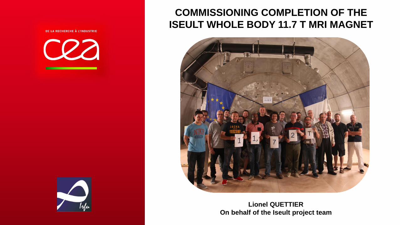
COMMISSIONING COMPLETION OF THE
ISEULT WHOLE BODY 11.7 T MRI MAGNET
Lionel QUETTIER
On behalf of the Iseult project team

• BACKGROUND
• DESIGN BASELINE
• MANUFACTURING
• INSTALLATION
• COMMISSIONING

IN RECENT DECADES NEUROSCIENCE MADE
EXTRAORDINARY PROGRESS
Neuroimaging
Cognitive
Neurosciences
Pathological brain singularityHuman brain singularity
PhysiquePhysics,
ElectronicsPhysique
Medicine
& BiologyPhysiqueMathematics
& StatisticsPhysiqueImage Processing Physique
Psychology
& Sociology
Clinical
Neurosciences
24th September 2019
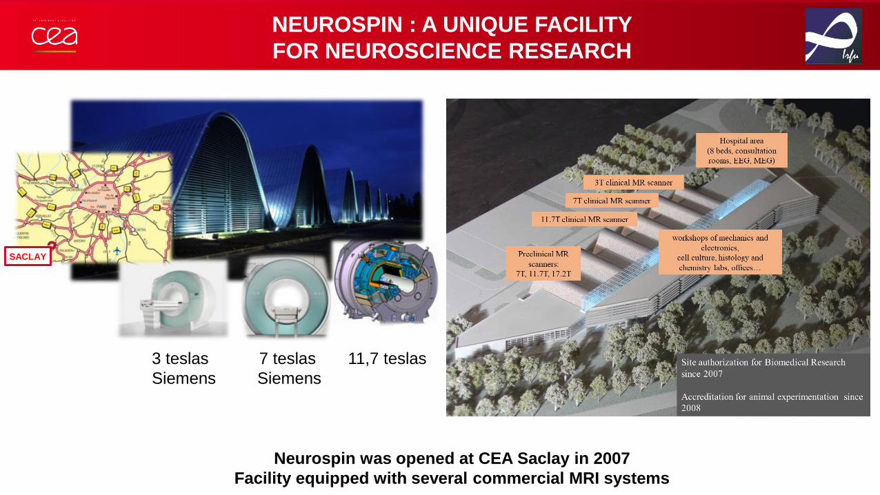
NEUROSPIN : A UNIQUE FACILITY
FOR NEUROSCIENCE RESEARCH
Observer
SACLAY
3 teslas 7 teslas 11,7 teslas
Siemens Siemens
Neurospin was opened at CEA Saclay in 2007
Facility equipped with several commercial MRI systems

SNRB01.65
Pohmann et al. Magn Reson Med 2016;75:801–809
SNR GAIN B0 : CLINICAL RESEARCH APPLICATIONS
7T3T
1 to 2 mm resolution 0.1 to 0.2 mm
resolution
11.7T (post-mortem)
Example of a human hippocampus image - Courtesy Neurospin/CEA
24th of September 2019Page 5
0.5 to 0.3 mm
resolution
At the ultra-high spatial resolution provided by 7T and soon 11.7T MRI :
High accuracy segmentation of the hippocampus becomes possible!
Highy interesting information for clinical research : Alzheimer’s Disease,
epilepsy, schizophrenia …

EARLY NMR IMAGING MAGNETS 1977 - 1981
Aberdeen 0.03T resistive magnet - 1977
0.15T Resistive magnet - 1980
John Woodgate and the first 0.3T NMR Imaging Magnet for EMI
First 1.5T magnet (STAR)
Courtesy G. Gilgrass
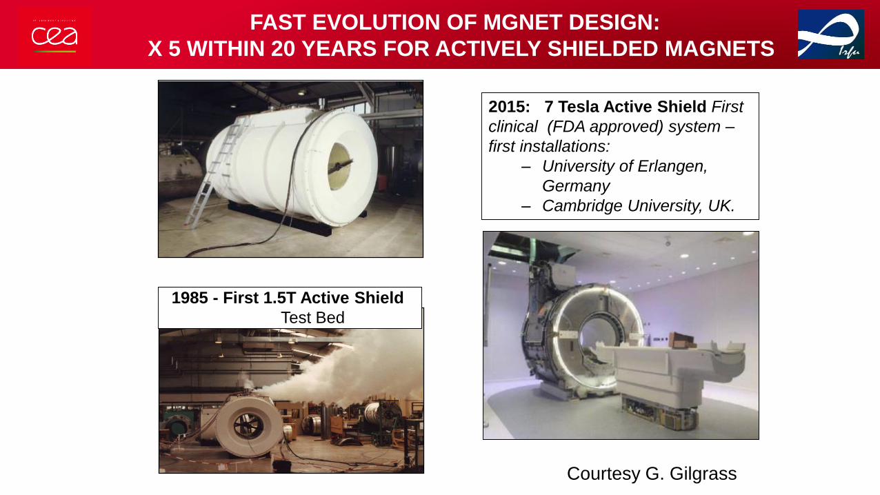
1985 - First 1.5T Active Shield
Test Bed
2015: 7 Tesla Active Shield First
clinical (FDA approved) system –
first installations:
– University of Erlangen,
Germany
– Cambridge University, UK.
Courtesy G. Gilgrass
FAST EVOLUTION OF MGNET DESIGN:
X 5 WITHIN 20 YEARS FOR ACTIVELY SHIELDED MAGNETS

WHOLE BODY MRI MAGNET TYPICAL SIZES
ObserverObserver
Observer
Field 1,5 T 3 T 7 T 11,75 T
G E - S H F J / C E A S i e m e n s S i e m e n s I s e u l t
Length
(m)1,25 - 1,7 1,6 - 1,8 ~ 3 4
Diameter
(m)1,9 - 2,1 1,90 - 2,1 > 2,50 4,6
Mass
(tons)~ 5 ~ 8 ~ 25 ~ 135
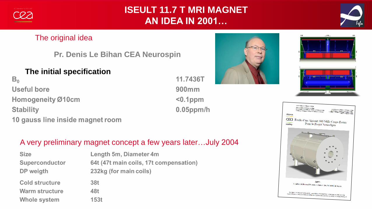
ISEULT 11.7 T MRI MAGNET
AN IDEA IN 2001…
The original idea
A very preliminary magnet concept a few years later…July 2004
The initial specification
Pr. Denis Le Bihan CEA Neurospin

THE ISEULT PROJET - A FRENCH GERMAN INITIATIVE
Observer
3 Workpackages
• Development of an ultra high field MRI
system (11.7T)
• Develop a new generation of gradient system
• Develop a new generation of contrast media
Ultra-hight field
MRI system
operating at 11.7T
Translational
research to
clinical magnets
(7T)
New contrast media
for Alzheimer’s
Disease, stroke
and Brain tumors)
CEA, SiemensSiemens,
Freiburg, Bruker
WP1 WP2 WP3
Guerbet, CEA
Observer
Alstom-GE
Oséo / BPI
Franco-German industrial collaboration developing :
“Molecular Imaging at Ultra High Magnetic Fields”
Agreement signed between Président Jacques Chirac and
Chancellor Gerhard Schröder in 2004.
Funding agreement for the French Consortium validated by
the French Industrial Innovation Agency in 2006.
Leader of French Consortium : Pharmaceutical Company
Guerbet

• BACKGROUND
• DESIGN BASELINE
• MANUFACTURING
• INSTALLATION
• COMMISSIONING

THE ISEULT MAGNET
ObserverObserver
Observer
11.7 T magnet section : in orange the windings,
in blue the mechanical structure at 1.8 K and
in violet the cryostat
A very tight specification:
• B0 / Aperture 11.72T (500 MHz for proton resonance)
• Aperture 900mm
• Field stability 0.05 ppm/h
• Homogeneity < 0.5 ppm on 22 cm DSV
• Stray field 5 G: 13.5 m axial, 10.5 m radial
Innovative solutions for a MRI magnet
• 170 NbTi double pancakes for the main coil
• 2 NbTi shielding coils to reduce the fringe field
• Cryostat for superfluid helium at 1.8 K, 1.25 bars
• Dedicated cryorefrigerator (80 l/h + 40 W @ 4.2 K)
• Driven mode operation, with two 1500 A power supplies
Stored Energy 338 MJ
Inductance 308 H
Current 1483 A
Length 5.2 m
Diameter 5 m
Weight 132 t

WINDINGS & CRYOSTABILITY
Conductor [ SC ]
Inter-turn
Insulation [ ITI ]
(impr. Kapton)
Inter-pancake
Insulation [ IPI ]
(fiberglass)
• Double pancake stacking
• 170 Double-Pancakes
• 82 turns
Main coil structure
(real size)
• Specific design for the Main Coil made of «wetted» double-pancakes to ensure the cryostability
• Shielding Coils are vacuum impregnated with epoxy resin
20 mm

THE OBJECTIVE IS TO DESIGN A MAGNET THEORETICALLY INTRINSICALLY HOMOGENEOUS
• BLOCK DESIGN
1 1
0 )(cos
sin
cos
)(cos),,(n
n
m
m
n
m
n
m
n
m
n
nn
n
z PW
mY
mX
PZrBrB
WINDINGS AND HOMOGENEITY
x
yz
O O’
2s
O’’
2s
CEA Patent WO/2007/077383
• SPECIAL PANCAKE LAYOUT

ISEULT HELIUM VESSEL ASSEMBLY PRINCIPLE
(1) Main Coil
(2) Shielding Coil
(3) MC outer cylinder
(4) MC base plate
(5) Spring washer stacks
(6) Cold mass end-plate
(7) Cold mass structure
(8) Cryoshim
(9) Helium vessel inner cylinder
(10) Coils connection pipe.
The key concept is that the main coil made of the stack of 170 double pancakes is only
mechanical linked to the helium vessel by its extremities with spring washers without
any inner mandrel or outer cylinder support.

COLD MASS ARCHITECTURE
PRELOAD SYSTEM
SC supporting

COLD MASS STRUCTURE
Main coil
Cold mass structure (2x) 4 tie rods ø40mm
titanium
Shielding
coil
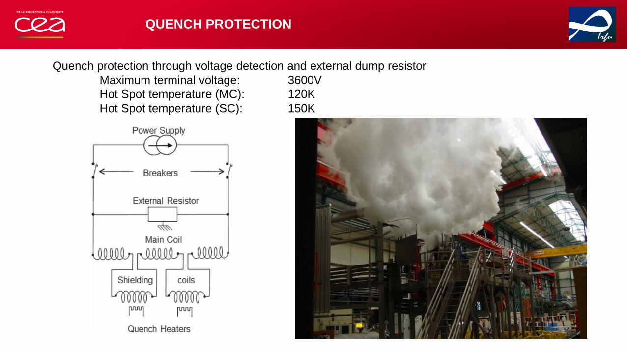
Quench protection through voltage detection and external dump resistor
Maximum terminal voltage: 3600V
Hot Spot temperature (MC): 120K
Hot Spot temperature (SC): 150K
QUENCH PROTECTION

pp
m
ppm
CEA Patent WO/2009/063150
Iseult electrical diagram
Fault current limiter (FCL) in series with a filtering
resistance Rf, in parallel with the magnet
The quench protection scheme and the risk of making superconducting joint using multi-strand cable
required the need of a power supply.
The specification of +/- 0,05 ppm/h cannot be reach with a stabilized power supply ( max. 1 ppm/h).
=> New concept to stabilize the magnetic field for Iseult
Fault current limiter (FCL) and filtering resistance
in parallel with the magnet and the power supply
Current stability on prototype magnet H0 (1.5 T, 900 A, 1H):
Validated on prototype magnets
ELECTRICAL SYSTEM
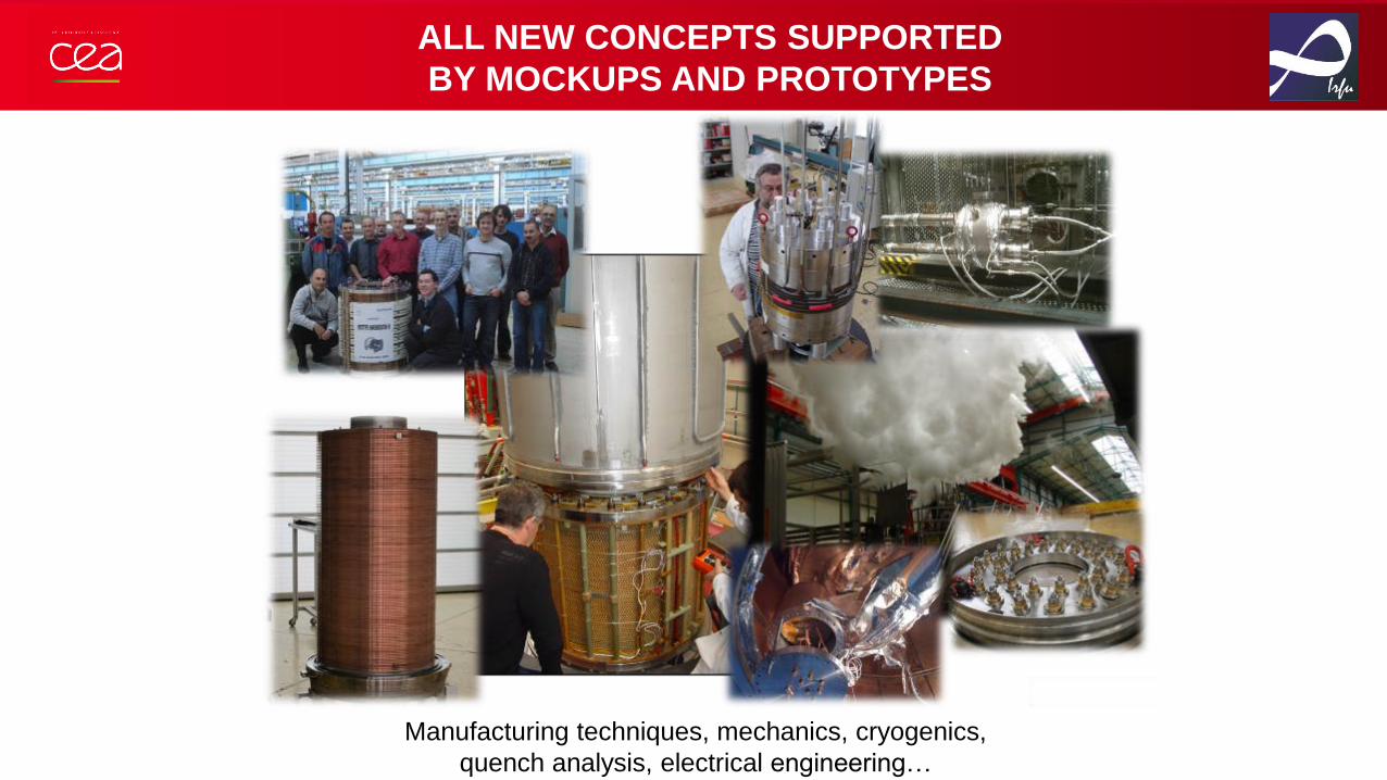
ALL NEW CONCEPTS SUPPORTED
BY MOCKUPS AND PROTOTYPES
Manufacturing techniques, mechanics, cryogenics,
quench analysis, electrical engineering…

• BACKGROUND
• DESIGN BASELINE
•MANUFACTURING
• INSTALLATION
• COMMISSIONING
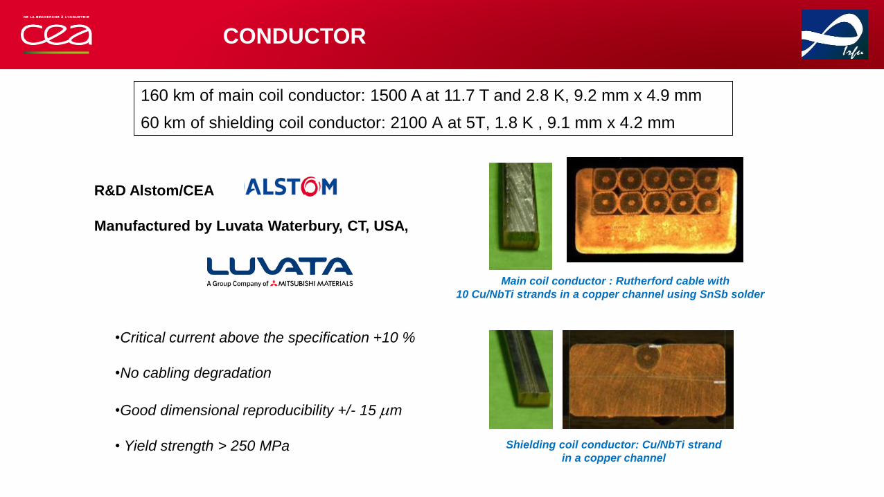
CONDUCTOR
160 km of main coil conductor: 1500 A at 11.7 T and 2.8 K, 9.2 mm x 4.9 mm
60 km of shielding coil conductor: 2100 A at 5T, 1.8 K , 9.1 mm x 4.2 mm
•Critical current above the specification +10 %
•No cabling degradation
•Good dimensional reproducibility +/- 15 mm
• Yield strength > 250 MPa
Main coil conductor : Rutherford cable with
10 Cu/NbTi strands in a copper channel using SnSb solder
Shielding coil conductor: Cu/NbTi strand
in a copper channel
R&D Alstom/CEA
Manufactured by Luvata Waterbury, CT, USA,
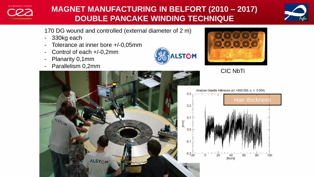
MAGNET MANUFACTURING IN BELFORT (2010 – 2017)
DOUBLE PANCAKE WINDING TECHNIQUE
170 DG wound and controlled (external diameter of 2 m)
- 330kg each
- Tolerance at inner bore +/-0,05mm
- Control of each +/-0,2mm
- Planarity 0,1mm
- Parallelism 0,2mm
Hair thickness
CIC NbTi

DOUBLE PANCAKE SERIES PRODUCTION
24
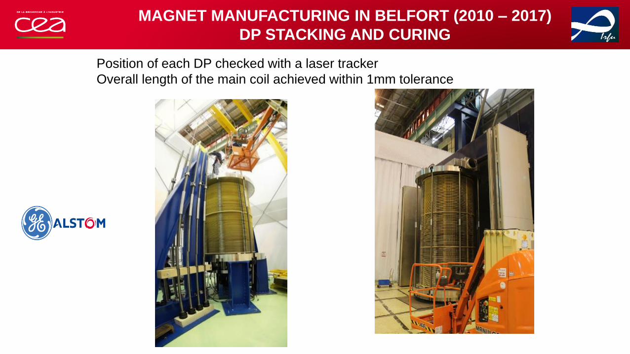
MAGNET MANUFACTURING IN BELFORT (2010 – 2017)
DP STACKING AND CURING
Position of each DP checked with a laser tracker
Overall length of the main coil achieved within 1mm tolerance
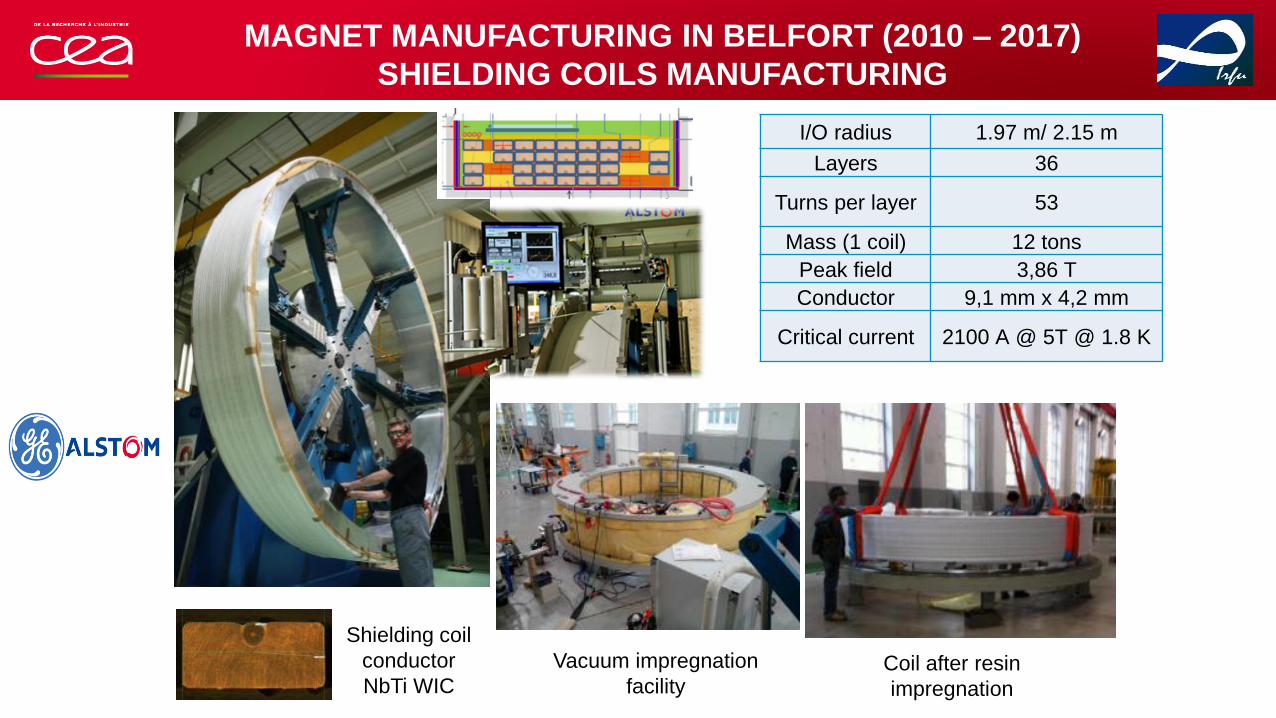
MAGNET MANUFACTURING IN BELFORT (2010 – 2017)
SHIELDING COILS MANUFACTURING
Observer
I/O radius 1.97 m/ 2.15 m
Layers 36
Turns per layer 53
Mass (1 coil) 12 tons
Peak field 3,86 T
Conductor 9,1 mm x 4,2 mm
Critical current 2100 A @ 5T @ 1.8 K
Shielding coil
conductor
NbTi WIC
Vacuum impregnation
facilityCoil after resin
impregnation
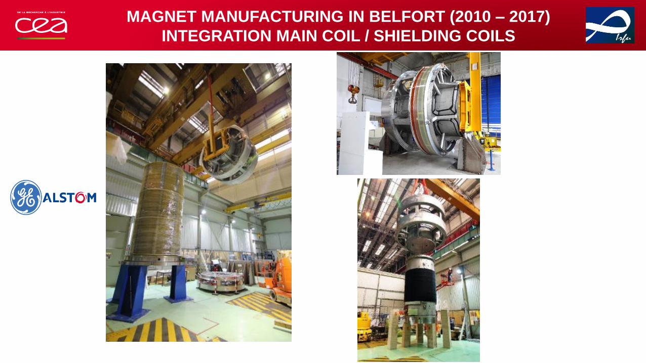
MAGNET MANUFACTURING IN BELFORT (2010 – 2017)
INTEGRATION MAIN COIL / SHIELDING COILS
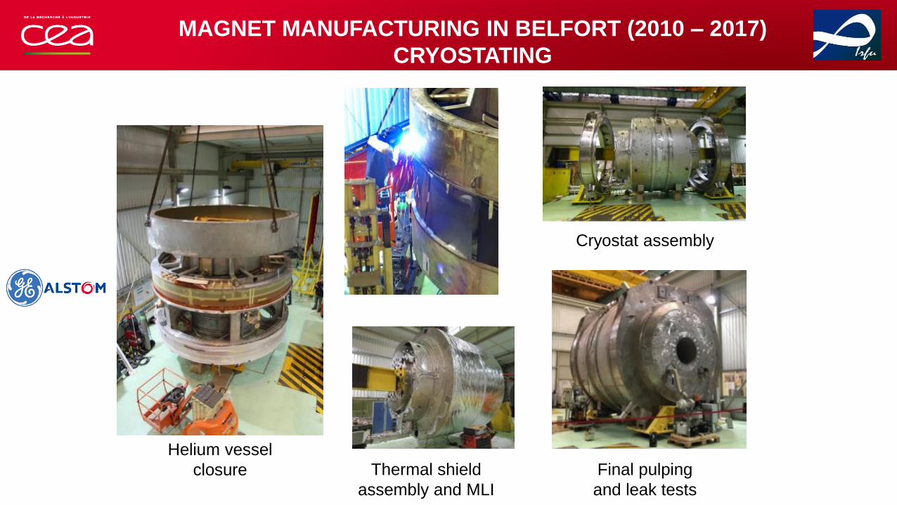
MAGNET MANUFACTURING IN BELFORT (2010 – 2017)
CRYOSTATING
Helium vessel
closure Thermal shield
assembly and MLI
Final pulping
and leak tests
Cryostat assembly

• BACKGROUND
• DESIGN BASELINE
• MANUFACTURING
• INSTALLATION
• COMMISSIONING

2 WEEKS OF TRANSPORT FROM BELFORT TO SACLAY
Belfort
Corbeil EssonnesSaclay
Strasbourg
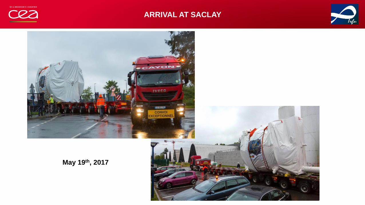
ARRIVAL AT SACLAY
May 19th, 2017
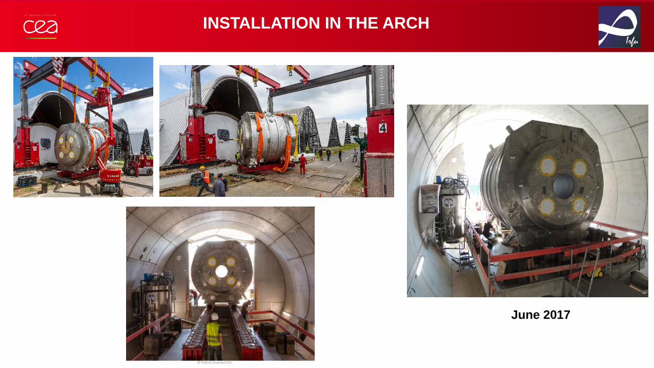
INSTALLATION IN THE ARCH
June 2017

Power
supplies
Magnet
control
room
A COMPLEX INSTALLATION TO OPERATE THE MAGNET
48 V
batteries
Vacuum
Circuit MSS/MCS
racks
Dump
Resistor
Cryogenic
plant
Commissioning started in 2010 Cryogenic satellite
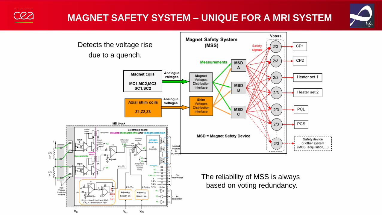
MAGNET SAFETY SYSTEM – UNIQUE FOR A MRI SYSTEM
The reliability of MSS is always
based on voting redundancy.
Detects the voltage rise
due to a quench.

GENERAL SCHEME OF THE CRYOGENIC EQUIPMENT
Gas
buffers
Proximity cryogenics :
External cryogenics :
• Make the magnet and cryogenics «independents»
• Use reliable technologies and redundancy of equipment
• Continuous operation in case of failure of cryoequipment

CRYOGENICS EQUIPMENTS
LHe Dewar -5000 l
(Cryotherm)
Air Liquide Refrigerator :
40W@4,5K & 80l/h at
rising level & 900W@44K
Compressors
Vacuum and helium pumps
He gasbag (recovery circuit)
135 m3

ROOM TEMPERATURE MAGNETIC MEASUREMENTS
Spherical Harmonic Expansion
• Same field quality in Belfort and at Neurospin
• Field uniformity can be achieved (even in case of cryoshim failure)
In ppm of 11.75T @ R=0,11m
1
1
0
)(cos
sin
cos
)(cos
),,(n
n
mm
n
m
n
m
n
m
n
nn
n
z
PW
mY
mX
PZ
rBrB
!)!1(
!)!1(
mn
mnW m
nwith
Test ID Z1 Z2 Z3 Z4 X11 Y11
Belfort -136 -111 15 9 -5 74
Saclay -132 -105 20 9 -1 59
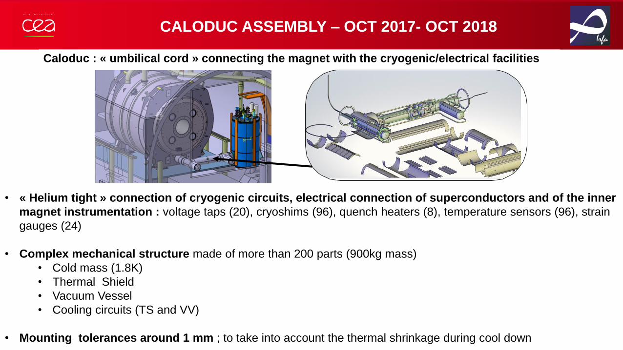
CALODUC ASSEMBLY – OCT 2017- OCT 2018
Caloduc : « umbilical cord » connecting the magnet with the cryogenic/electrical facilities
• « Helium tight » connection of cryogenic circuits, electrical connection of superconductors and of the inner
magnet instrumentation : voltage taps (20), cryoshims (96), quench heaters (8), temperature sensors (96), strain
gauges (24)
• Complex mechanical structure made of more than 200 parts (900kg mass)
• Cold mass (1.8K)
• Thermal Shield
• Vacuum Vessel
• Cooling circuits (TS and VV)
• Mounting tolerances around 1 mm ; to take into account the thermal shrinkage during cool down

Dye penetrant tests
CALODUC ASSEMBLY – OCT 2017- OCT 2018
MLI Thermal shield
Vacuum vesselwelding
Helium vessel assembly Innovative engineering techniques
(duct tape, wood shims, manual lifting jacks)…
Cooling tubes
local leak tests
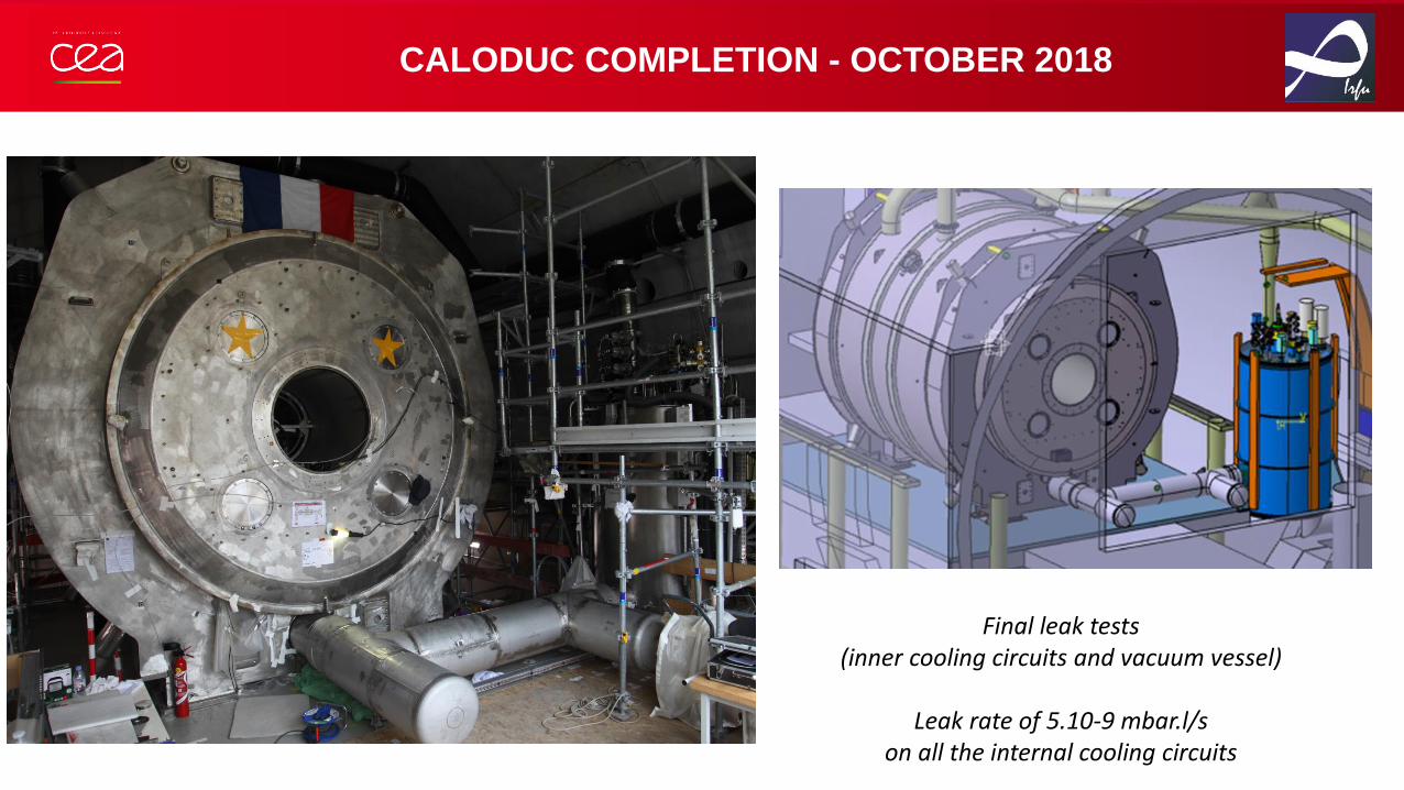
CALODUC COMPLETION - OCTOBER 2018
Final leak tests (inner cooling circuits and vacuum vessel)
Leak rate of 5.10-9 mbar.l/s on all the internal cooling circuits
• BACKGROUND
• DESIGN BASELINE
• MANUFACTURING
• INSTALLATION
• COMMISSIONING

COOLDOWN – 19 NOV 2018 – 7 MARCH 2019
• Huge mass to cool down: cold mass (105 tons @ 1.8K) + thermal shield (3.4 tons @ 55K)
• Coolding rate limited by the thermal gradients across the coils (50K max)
Température masse froide
250 000 L liquid nitrogen
18 500 L helium (filling and cooling down)
150 kW of electrical power to operate the cryoplant
Power outage
Cooldown with nitrogen
(thermal shield and cold mass)
7 weeks
Turbo expander pumps activation
Cooldown with helium (thermal shield and cold mass)
5 weeks
Pumping units activation
Cold mass filling with helium
Cooldown from 4.2K to 1.8K
4 weeks
Cold mass temperature
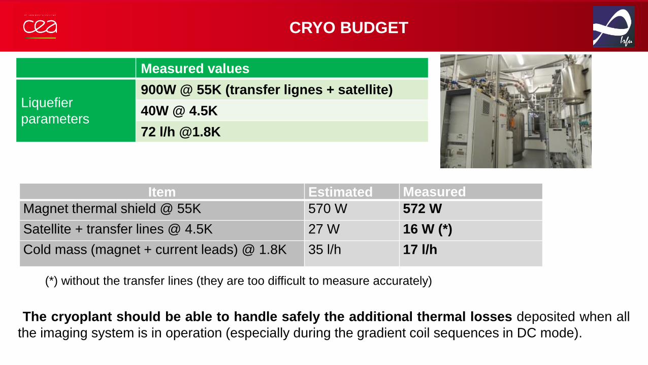
CRYO BUDGET
Measured values
Liquefier
parameters
900W @ 55K (transfer lignes + satellite)
40W @ 4.5K
72 l/h @1.8K
(*) without the transfer lines (they are too difficult to measure accurately)
Item Estimated Measured
Magnet thermal shield @ 55K 570 W 572 W
Satellite + transfer lines @ 4.5K 27 W 16 W (*)
Cold mass (magnet + current leads) @ 1.8K 35 l/h 17 l/h
The cryoplant should be able to handle safely the additional thermal losses deposited when all
the imaging system is in operation (especially during the gradient coil sequences in DC mode).

FIELD MEASUREMENTS DURING THE COOLING PHASE
30K
300K
270K
240K
210K
180K
150K
120K
90K
60K
88 ppm max
inhomogeneity
190 ppm max inhomogeneity
sur Ø 22 cm
X
Z
Y
0K
80K
COLD MASS
TEMPERATURE
+/-0,5A ; B=1,5mT
Fluxgate probes

STEP BY STEP ENERGIZATION
• Insulation tests (magnet @ 3.6kV and instrumentation @ 500V)
• Tests of the Magnetic Safety System and thresholds setup (1V / 750ms)
• Fast discharge tests triggered with the emergency buttons
• Slow discharge tests
• Magnetic measurements
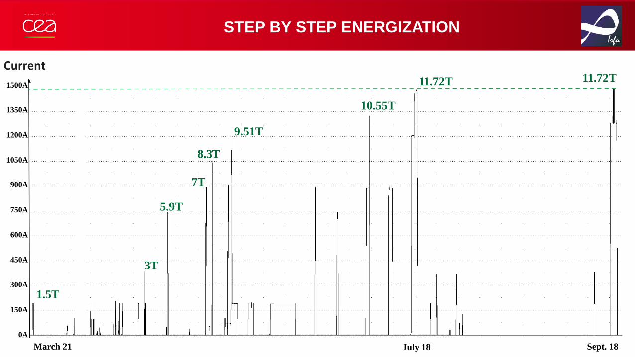
STEP BY STEP ENERGIZATION
Current
1350A
1200A
1050A
900A
600A
450A
300A
150A
0A
750A
1500A
1.5T
3T
7T
5.9T
8.3T
March 21
11.72T
10.55T
9.51T
July 18 Sept. 18
11.72T
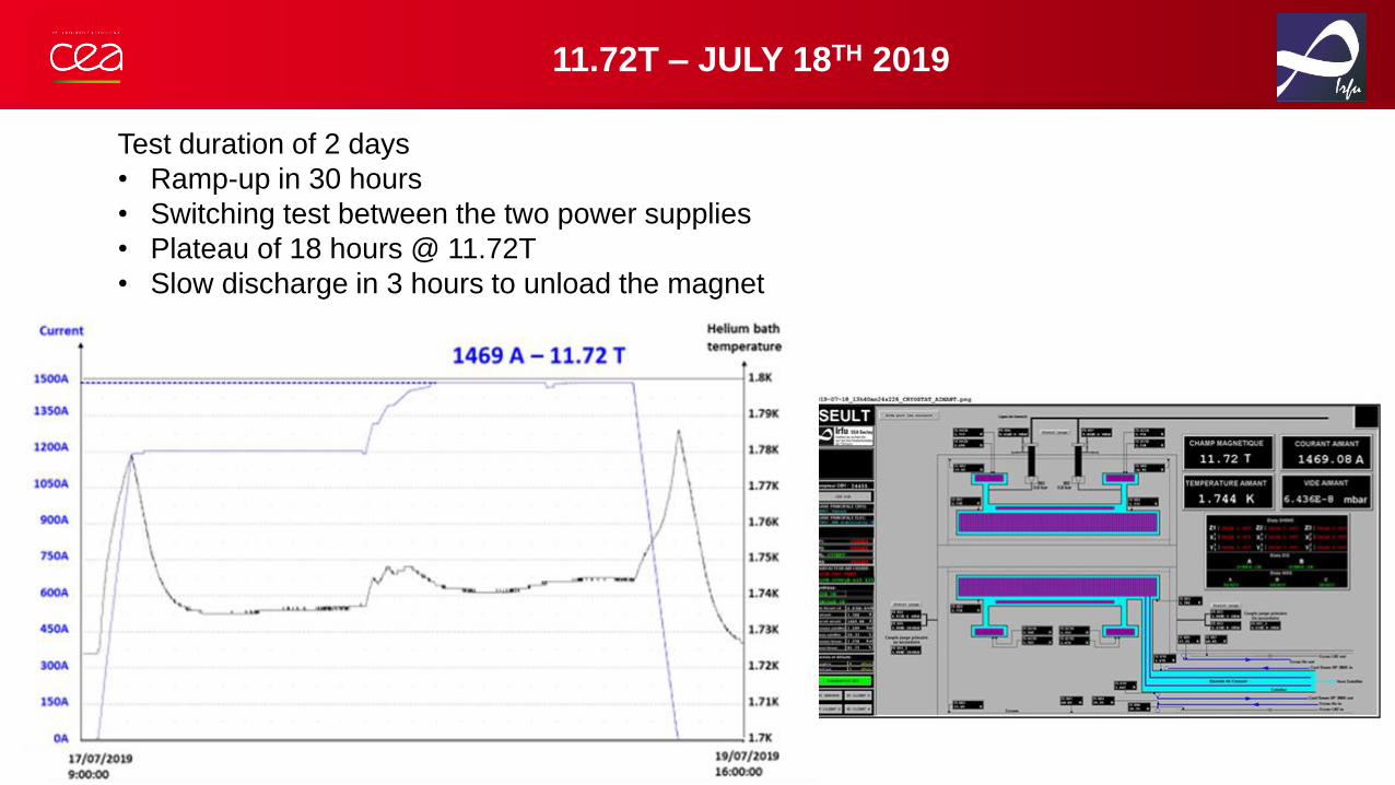
11.72T – JULY 18TH 2019
Test duration of 2 days
• Ramp-up in 30 hours
• Switching test between the two power supplies
• Plateau of 18 hours @ 11.72T
• Slow discharge in 3 hours to unload the magnet
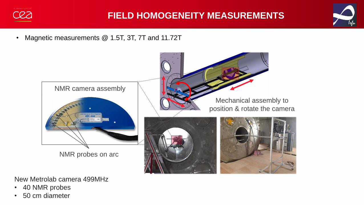
FIELD HOMOGENEITY MEASUREMENTS
• Magnetic measurements @ 1.5T, 3T, 7T and 11.72T
New Metrolab camera 499MHz
• 40 NMR probes
• 50 cm diameter
NMR probes on arc
NMR camera assembly
Mechanical assembly to
position & rotate the camera
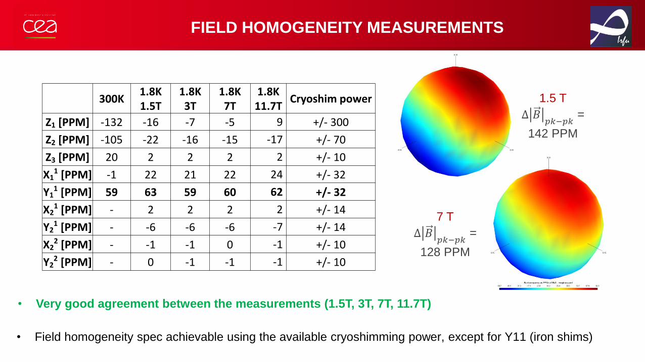
FIELD HOMOGENEITY MEASUREMENTS
• Very good agreement between the measurements (1.5T, 3T, 7T, 11.7T)
• Field homogeneity spec achievable using the available cryoshimming power, except for Y11 (iron shims)
300K1.8K1.5T
1.8K3T
1.8K7T
1.8K11.7T
Cryoshim power
Z1 [PPM] -132 -16 -7 -5 9 +/- 300
Z2 [PPM] -105 -22 -16 -15 -17 +/- 70
Z3 [PPM] 20 2 2 2 2 +/- 10
X11 [PPM] -1 22 21 22 24 +/- 32
Y11 [PPM] 59 63 59 60 62 +/- 32
X21 [PPM] - 2 2 2 2 +/- 14
Y21 [PPM] - -6 -6 -6 -7 +/- 14
X22 [PPM] - -1 -1 0 -1 +/- 10
Y22 [PPM] - 0 -1 -1 -1 +/- 10
1.5 T
∆ 𝐵𝑝𝑘−𝑝𝑘
=
142 PPM
7 T
∆ 𝐵𝑝𝑘−𝑝𝑘
=
128 PPM
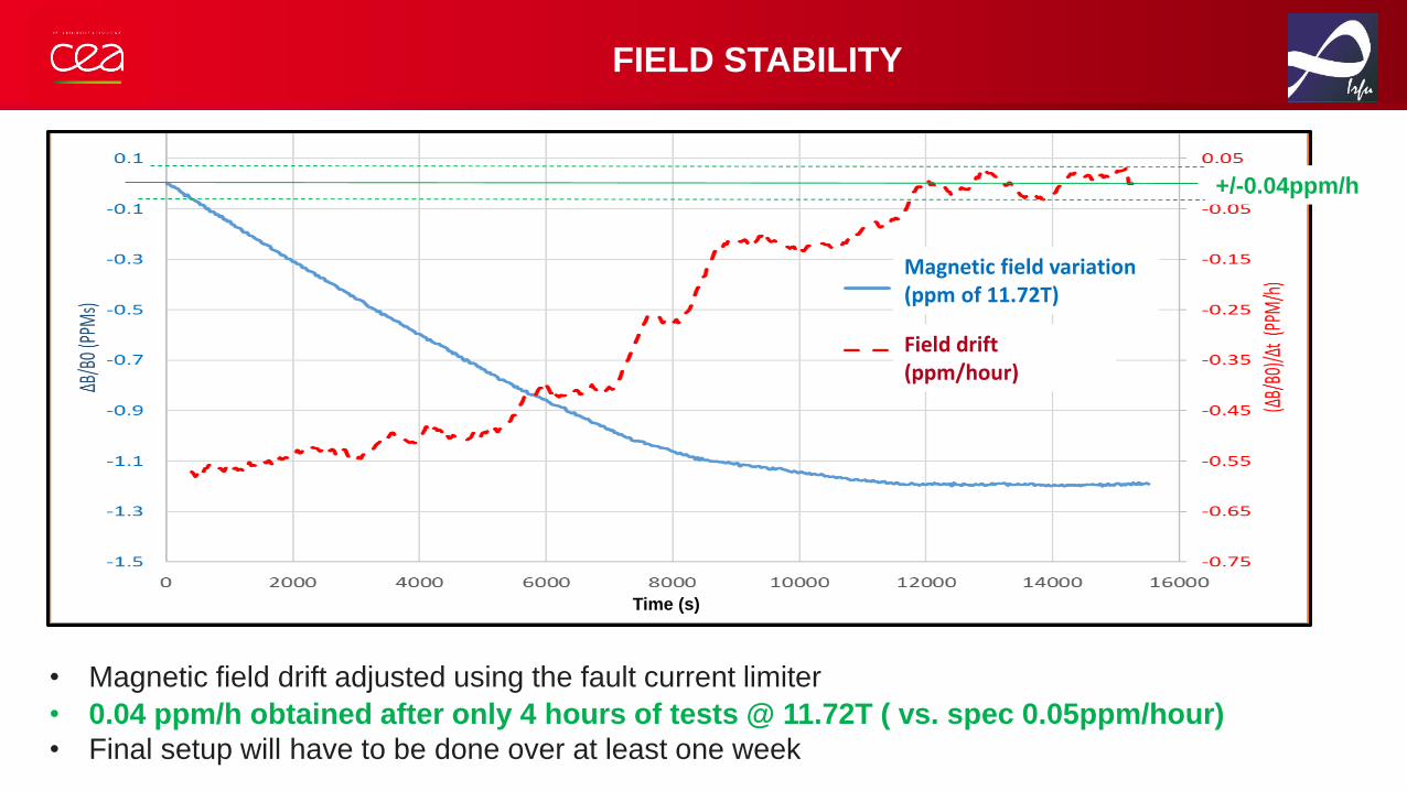
FIELD STABILITY
• 0.04 ppm/h obtained after only 4 hours of tests @ 11.72T ( vs. spec 0.05ppm/hour)
• Final setup will have to be done over at least one week
Magnetic field variation (ppm of 11.72T)
Field drift (ppm/hour)
Time (s)
+/-0.04ppm/h
• Magnetic field drift adjusted using the fault current limiter

FINAL COMMISSIONING STEPS OF THE ISEULT MRI SYSTEM
• Installation of the Faraday cages (on-going)
• Installation of the MRI equipment (Gradient Coils, RF antenna)
and of the patient bed
• Final energization step by step
• Commissioning of the high-availability control and protection systems
• Adjustment of the field homogeneity (iron shims – cryoshims)
• Adjustment of the field stability
• Tests of the Gradient Coils vs. main magnet interaction : the most critical object
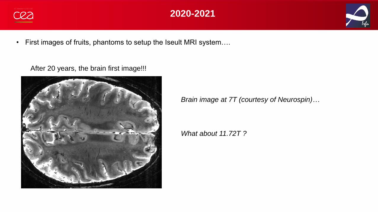
2020-2021
After 20 years, the brain first image!!!
• First images of fruits, phantoms to setup the Iseult MRI system….
Brain image at 7T (courtesy of Neurospin)…
What about 11.72T ?

2019
- 7T : ~ 100 systems -– 6 to 10 new units per year
- 1 system 8T WB: Ohio State Univ (80cm)
- 6 systems 9.4T WB: Minneapolis (65cm), Chicago (80cm), Tübingen (82cm),
Jülich (90cm), Maastricht (82cm), Beijing (83cm)
- 1 system 10,5T WB: Minneapolis – 88cm – Passive shielding, humain brain images since 2018
- 3 projects WB 11.7T:
- Iseult: 90cm/active shielding, NIH/Bethesda: 68cm/passive shielding, NRI (Séoul): 68cm/passive shielding
Future projects @ 14T : USA (Boston, Stanford), Chine (Beijing, Shenzhen)
2001
- 3T : 100 systems
- 2 systems 7T Whole Body (WB)
- 1 systems 8T WB
MRI WORLD-WIDE PARK EVOLUTION
Warm thanks to all the people involved
in this crazy adventure !!!