commissioning august & september. 2 agenda 11:20 coffee 11:30 introduction sue s 11:35 controls...
TRANSCRIPT

Commissioning
August & September

2
Agenda
11:20 Coffee11:30 Introduction Sue S11:35 Controls (an overview) Brian M10:55 Controls & Data Acquisition Software Ben S12:15 RF Systems TBC12:40 Machine protection Steve B13:00 Lunch14:00 Magnets Ben S14:15 Laser Steve J14:40 Cryogenics TBC15:00 Injector Rob S 15:20 Diagnostics Rob S15:40 Coffee15:55 Vacuum Keith M16:15 Commissioning Sue S16:35 The End!!!
Speakers, please note that we have to strictly stick to
time!!!

3
Programme
• Ramp down to 100 C (5c/hr) Fri 25/7/08• HV Commissioning Monday 4/8/08
» SRS Switch off!!
• First ALICE scheduled shutdown October 08

4
GOOD
BAD

5
Gun & cathode work : Summary
• Bakeout 200 degrees (20 degrees less than usual)• HV Gun conditioning
– Aim for minimum volts for stable conditions 370kV!
• Wafer heat clean & HV tests – If FE is present, commission at reduced voltage
• Cathode activation • Cathode HV conditioning (usual 365kV)
– If the FE is present, decide what gun voltage to use (below 350kV)
• Decide on what bunch charge to use– probably ~40pC ?

6
GUN – to - BOOSTER
SOL-01
H&V-01
H&V-06BPM-01
BUNCHERYAG-01
SOL-02
H&V-02 BPM-02

7
GUN – to - BOOSTER
• Set the “commissioning” bunch charge– use QE scan results for estimates :
• SOL-01 scan– required to set SOL-01 correctly for a
given Q
• Cross -calibrate BPM-01 and YAG-01 (skip if Lifetime low)
• Set SOL-01 and SOL-02• Steer the beam to the entrance of
the booster• Set the buncher zero-crossing
phase
BOO
STER
GU
N
SOL-01
H&V-01
H&V-06BPM-01
BUNCHERYAG-01
SOL-02
H&V-02 BPM-02

8
Booster to Linac
LINAC
BOO
STER
Q-01
YAG-02 Q-02
BPM-03
H&V-03 Q-03
Q-04
YAG-03
DIP-01
Q-05
DIP-02
YAG-??
FCUP-01
BPM-04H&V-04
Q-06Q-07
Q-08Q-09
DIP-3
Q-10
YAG-04
Q-11 BPM-05H&V-05
Q-12
OTR-01BPM-01H&V-01
DIP-03
Twiss parametersEmittance
Slit here
Energy spread/spectrumAbsolute energy Buncher gradient / phase setting
Bunch charge
Setting achromaticcondition (Q01-Q05)
Twiss parametersEnergy spread
Setting achromaticcondition (Q10, Q12)
9
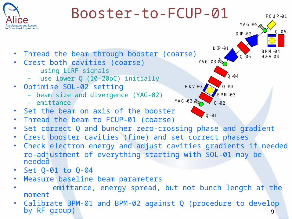
Booster-to-FCUP-01
• Thread the beam through booster (coarse)• Crest both cavities (coarse)
– using LLRF signals– use lower Q (10-20pC) initially
• Optimise SOL-02 setting – beam size and divergence (YAG-02)– emittance
• Set the beam on axis of the booster• Thread the beam to FCUP-01 (coarse)• Set correct Q and buncher zero-crossing phase and gradient• Crest booster cavities (fine) and set correct phases• Check electron energy and adjust cavities gradients if needed
re-adjustment of everything starting with SOL-01 may be needed• Set Q-01 to Q-04• Measure baseline beam parameters• emittance, energy spread, but not bunch length at the moment• Calibrate BPM-01 and BPM-02 against Q (procedure to develop by RF group)
Q-01
YAG-02 Q-02
BPM-03
H&V-03 Q-03
Q-04
YAG-03
DIP-01
Q-05
DIP-02
YAG-05
FCUP-01
BPM-04H&V-04
Q-06

10
The rest of the Injector : Summary
• Set DIP-01 and DIP-2 (dispersion suppression)• Thread beam through dog-leg section (coarse)• Set dog-leg section (fine); dispersion
suppression• Match the beam to main linac
– perhaps beam size and position only
• Beam measurements – probably, need none at the energy recovery stage
FCUP-01
Q-06Q-07
Q-08Q-09
DIP-3
Q-10
YAG-04
Q-11 BPM-05H&V-05
Q-12
INJECTOR ST1
ARC 2
ST4
OTR-01Q-01 Q-02 Q-03 Q-04 Q-05
YAG-03
DIP-01
Q-05
DIP-02
YAG-05
FCUP-01
BPM-04H&V-04
Q-06Q-07
Q-08
ARC 2
ST4
11
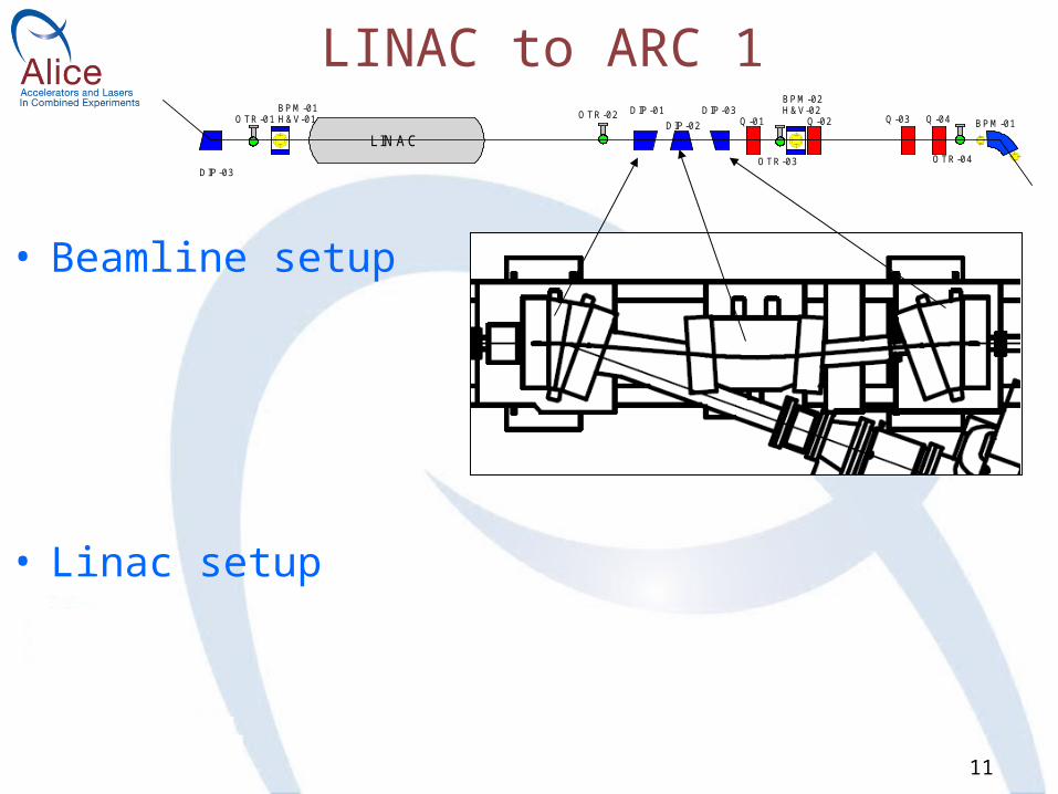
LINAC to ARC 1
LINACOTR-01
BPM-01H&V-01 OTR-02 DIP-01
DIP-02DIP-03
Q-01
OTR-03
BPM-02H&V-02
Q-02 Q-03 Q-04
OTR-04
BPM-01
DIP-03
• Beamline setup
• Linac setup

12
ARC 1
• 180 deg. bend condition• Symmetric optics in the arc• Cancellation of dispersion at the ARC1 exit
– will not be easy without BPMs; – fine tuning may need to be left for later
• R56 control (cancellation)– not now !
• Sextupole tuning – again, better be left for later
BPM-01DIP-01
BPM-02SEXT-01
OTR-01
ARC1
Q-01
V-01
Q-02
BPM-03
DIP-02
BPM-04
Q-03
V-02
Q-04
OTR-02SEXT-02
BPM-05DIP-03
BPM-06

13
ST2 & ST3
• Get the beam to OTR-01 (ST3)– no viewers over ~8m distance !!– beam divergence after the chicane is not too large – hence try to catch the beam on OTR-01 (ST3) without
quads
• Check dispersion in ST3– use OTR-01
• Estimate an energy spread on OTR-03 (ST2)• Measure Twiss parameters at the entrance to the
ARC2
ARC1
DIP-03BPM-06
OTR-01
Q-01Q-02
BPM-01H&V-01
OTR-02
Q-03Q-04
BPM-02H&V-02DIP-01
DIP-02V-03
OTR-03
DIP-03
DIP-04Q-05
ST 2ST 2
ARC 2 PLM-01TCM-01
BPM-04H&V-04
BPM-05H&V-05
BPM-01H&V-01
Q-06Q-07
WIGGLER
ST 3ST 3
Q-01Q-02
Q-03Q-04
OTR-01
BPM-02H&V-02
BPM-01DIP-01

14
ARC 2
ARC 2
BPM-01DIP-01
BPM-02SEXT-01
OTR-01
Q-01
V-01
Q-02
BPM-03
BPM-03Q-03
V-02
Q-04
OTR-02SEXT-02BPM-05
DIP-03BPM-06

15
STR 4
LINAC
YAG-04 Q-12
OTR-01BPM-01H&V-01
OTR-02SEXT-02BPM-05
OTR-01Q-01 Q-02
BPM-01H&V-01
Q-03
DUMP-01
Q-04 Q-05
BPM-02H&V-02
OTR-02DIP-01 DIP-02 DIP-03
DO NOT TOUCH !!!• 1. Get beam to OTR-2– try it with all quads OFF (by~ 60m on OTR-02)– use VCOR-02 (ARC2) and DIP-03 (ARC2)– set beam size on OTR-02 : beta ~ 6m (x) and ~10m (y) (quads to nominal; adjust if necessary)
• 2. Get beam to OTR-01 (ST1)– do not touch DIP-03– remember the hole in OTR-01 !– centre the beam on OTR-01 (ST1)
• use HVCOR-02 • note corrector settings for the beam symmetric wrt the OTR centre• set the average current in the correctors
• 3. Get beam to OTR-02 (ST1) – scan HVCOR-02 (ST4) – remember the hole !– do not use HVCOR-01 (ST1) – Setup for 8MeV beams !!!

16
Energy Recovery• AIMS:• get 180 degrees phase difference between the
outcoming and incoming beams• catch the beam in the dump• HOW:• move the ARC1
LINAC
Q-12
OTR-01BPM-01H&V-01
ST1
OTR-02 DIP-01DIP-02
DIP-03Q-01
OTR-03
BPM-02H&V-02
Q-02
DIP-02 DIP-03BPM-01
Q-01Q-02
Q-03OTR-01
DMP
1 m
Note: scale is for guidance only

17
Call the big bossOpen champagne