commissioning atca mss - xa.yimg.comxa.yimg.com/.../name/commissioning+atca+mss.pdf ·...
TRANSCRIPT
Commissioning ATCA MSS
Issue 1-0

2Issue 1-0
Commissioning ATCA MSS
Id:0900d8058079b642
The information in this document is subject to change without notice and describes only the product defined in the introduction of this documentation. This documentation is intended for the use of Nokia Siemens Networks customers only for the purposes of the agreement under which the document is submitted, and no part of it may be used, reproduced, modified or transmitted in any form or means without the prior written permission of Nokia Siemens Networks. The documentation has been prepared to be used by professional and properly trained personnel, and the customer assumes full responsibility when using it. Nokia Siemens Networks welcomes customer comments as part of the process of continuous development and improvement of the documentation.
The information or statements given in this documentation concerning the suitability, capacity, or performance of the mentioned hardware or software products are given "as is" and all liability arising in connection with such hardware or software products shall be defined conclusively and finally in a separate agreement between Nokia Siemens Networks and the customer. However, Nokia Siemens Networks has made all reasonable efforts to ensure that the instructions contained in the document are adequate and free of material errors and omissions. Nokia Siemens Networks will, if deemed necessary by Nokia Siemens Networks, explain issues which may not be covered by the document.
Nokia Siemens Networks will correct errors in this documentation as soon as possible. IN NO EVENT WILL Nokia Siemens Networks BE LIABLE FOR ERRORS IN THIS DOCUMENTA-TION OR FOR ANY DAMAGES, INCLUDING BUT NOT LIMITED TO SPECIAL, DIRECT, INDI-RECT, INCIDENTAL OR CONSEQUENTIAL OR ANY LOSSES, SUCH AS BUT NOT LIMITED TO LOSS OF PROFIT, REVENUE, BUSINESS INTERRUPTION, BUSINESS OPPORTUNITY OR DATA,THAT MAY ARISE FROM THE USE OF THIS DOCUMENT OR THE INFORMATION IN IT.
This documentation and the product it describes are considered protected by copyrights and other intellectual property rights according to the applicable laws.
The wave logo is a trademark of Nokia Siemens Networks Oy. Nokia is a registered trademark of Nokia Corporation. Siemens is a registered trademark of Siemens AG.
Other product names mentioned in this document may be trademarks of their respective owners, and they are mentioned for identification purposes only.
Copyright © Nokia Siemens Networks 2010/9/29. All rights reserved
f Important Notice on Product Safety Elevated voltages are inevitably present at specific points in this electrical equipment. Some of the parts may also have elevated operating temperatures.
Non-observance of these conditions and the safety instructions can result in personal injury or in property damage.
Therefore, only trained and qualified personnel may install and maintain the system.
The system complies with the standard EN 60950 / IEC 60950. All equipment connected has to comply with the applicable safety standards.
The same text in German:
Wichtiger Hinweis zur Produktsicherheit
In elektrischen Anlagen stehen zwangsläufig bestimmte Teile der Geräte unter Span-nung. Einige Teile können auch eine hohe Betriebstemperatur aufweisen.
Eine Nichtbeachtung dieser Situation und der Warnungshinweise kann zu Körperverlet-zungen und Sachschäden führen.
Deshalb wird vorausgesetzt, dass nur geschultes und qualifiziertes Personal die Anlagen installiert und wartet.
Das System entspricht den Anforderungen der EN 60950 / IEC 60950. Angeschlossene Geräte müssen die zutreffenden Sicherheitsbestimmungen erfüllen.

Issue 1-03
Commissioning ATCA MSS
Id:0900d8058079b642
Table of ContentsThis document has 81 pages.
1 Commissioning preparations . . . . . . . . . . . . . . . . . . . . . . . . . . . . . . . . . . 71.1 Equipment needed for the initial inspections and testing. . . . . . . . . . . . . 71.2 Related documents . . . . . . . . . . . . . . . . . . . . . . . . . . . . . . . . . . . . . . . . . 7
2 Initial inspections . . . . . . . . . . . . . . . . . . . . . . . . . . . . . . . . . . . . . . . . . . . 82.1 Checking the settings and the configuration . . . . . . . . . . . . . . . . . . . . . . 82.2 Inspecting the storage devices . . . . . . . . . . . . . . . . . . . . . . . . . . . . . . . 192.3 Creating a bootable USB stick and copying a minidebugger to it . . . . . 192.4 Updating minidebugger build and copying it to USB memory stick . . . . 20
3 Opening the first MML session . . . . . . . . . . . . . . . . . . . . . . . . . . . . . . . 223.1 Configuring the IP address with OMU serial port and VIMMLA. . . . . . . 223.2 Opening the first MML session via TELNET . . . . . . . . . . . . . . . . . . . . . 223.3 Creating system name. . . . . . . . . . . . . . . . . . . . . . . . . . . . . . . . . . . . . . 233.4 Configuring the service terminal for alarms (optional) . . . . . . . . . . . . . . 23
4 Checking the start-up. . . . . . . . . . . . . . . . . . . . . . . . . . . . . . . . . . . . . . . 264.1 Monitoring the start-up of the units . . . . . . . . . . . . . . . . . . . . . . . . . . . . 264.2 Inspecting the EMB connections . . . . . . . . . . . . . . . . . . . . . . . . . . . . . . 26
5 Inspecting ATCA MSS software versions . . . . . . . . . . . . . . . . . . . . . . . 325.1 Inspecting software versions . . . . . . . . . . . . . . . . . . . . . . . . . . . . . . . . . 325.2 Inspecting embedded software versions . . . . . . . . . . . . . . . . . . . . . . . . 33
6 Inspecting I/O devices . . . . . . . . . . . . . . . . . . . . . . . . . . . . . . . . . . . . . . 37
7 Inspecting maintenance system. . . . . . . . . . . . . . . . . . . . . . . . . . . . . . . 417.1 Testing the hardware alarms . . . . . . . . . . . . . . . . . . . . . . . . . . . . . . . . . 417.2 Testing the recovery from a complete power break in the system. . . . . 41
8 Checking the hardware configuration . . . . . . . . . . . . . . . . . . . . . . . . . . 438.1 Printing out the hardware configuration . . . . . . . . . . . . . . . . . . . . . . . . . 438.2 Checking the LAN device configuration . . . . . . . . . . . . . . . . . . . . . . . . . 448.3 Inspecting the LAN (Ethernet) switches. . . . . . . . . . . . . . . . . . . . . . . . . 46
9 Checking unit diagnostics and working states . . . . . . . . . . . . . . . . . . . . 489.1 Changing the states and the diagnosing of the units . . . . . . . . . . . . . . . 499.2 Testing the spare units . . . . . . . . . . . . . . . . . . . . . . . . . . . . . . . . . . . . . 50
10 Copying additional software. . . . . . . . . . . . . . . . . . . . . . . . . . . . . . . . . . 51
11 Initial hardware setup. . . . . . . . . . . . . . . . . . . . . . . . . . . . . . . . . . . . . . . 52
12 Build installation . . . . . . . . . . . . . . . . . . . . . . . . . . . . . . . . . . . . . . . . . . . 5312.1 Initial software build in the USB . . . . . . . . . . . . . . . . . . . . . . . . . . . . . . . 5312.2 Copying the build to the target element disk . . . . . . . . . . . . . . . . . . . . . 5312.3 Copying the first build to the network element . . . . . . . . . . . . . . . . . . . . 53
13 Shelf manager . . . . . . . . . . . . . . . . . . . . . . . . . . . . . . . . . . . . . . . . . . . . 5513.1 Sessions to shelf manager . . . . . . . . . . . . . . . . . . . . . . . . . . . . . . . . . . 5513.2 Shelf manager IP addresses . . . . . . . . . . . . . . . . . . . . . . . . . . . . . . . . . 56

4Issue 1-0
Commissioning ATCA MSS
Id:0900d8058079b642
13.3 Telnet connection from OMU to shelf manager . . . . . . . . . . . . . . . . . . . 57
14 AHUB3-A troubleshooting. . . . . . . . . . . . . . . . . . . . . . . . . . . . . . . . . . . . 5914.1 Ports remain disabled . . . . . . . . . . . . . . . . . . . . . . . . . . . . . . . . . . . . . . . 5914.2 AHUB3-A does not get the IP address or the IP address is wrong. . . . . 5914.3 Firmware versions. . . . . . . . . . . . . . . . . . . . . . . . . . . . . . . . . . . . . . . . . . 6114.4 Problems with SNMP . . . . . . . . . . . . . . . . . . . . . . . . . . . . . . . . . . . . . . . 61
15 DMX units . . . . . . . . . . . . . . . . . . . . . . . . . . . . . . . . . . . . . . . . . . . . . . . . 63
16 VMU or other units . . . . . . . . . . . . . . . . . . . . . . . . . . . . . . . . . . . . . . . . . 6416.1 BIOS settings . . . . . . . . . . . . . . . . . . . . . . . . . . . . . . . . . . . . . . . . . . . . . 6416.2 Incorrect amount of memory in VMU . . . . . . . . . . . . . . . . . . . . . . . . . . . 6416.3 VMAKVM file. . . . . . . . . . . . . . . . . . . . . . . . . . . . . . . . . . . . . . . . . . . . . . 6516.4 Handling virtual units. . . . . . . . . . . . . . . . . . . . . . . . . . . . . . . . . . . . . . . . 6516.5 List of Programs: lnx-launcher . . . . . . . . . . . . . . . . . . . . . . . . . . . . . . . . 6616.6 List of Programs: ps -x . . . . . . . . . . . . . . . . . . . . . . . . . . . . . . . . . . . . . . 6816.7 List of LinDX software modules . . . . . . . . . . . . . . . . . . . . . . . . . . . . . . . 6916.8 DX Error codes in Linux unit . . . . . . . . . . . . . . . . . . . . . . . . . . . . . . . . . . 6916.9 Copying files from Linux unit to OMU disk . . . . . . . . . . . . . . . . . . . . . . . 6916.10 LinDX command help . . . . . . . . . . . . . . . . . . . . . . . . . . . . . . . . . . . . . . . 7016.11 Extended Message Monitoring from Linux unit. . . . . . . . . . . . . . . . . . . . 7016.12 Message monitoring in Linux unit . . . . . . . . . . . . . . . . . . . . . . . . . . . . . . 7016.13 Logs in Linux units . . . . . . . . . . . . . . . . . . . . . . . . . . . . . . . . . . . . . . . . . 7116.14 Memory Usage in Linux units . . . . . . . . . . . . . . . . . . . . . . . . . . . . . . . . . 7216.15 System Information in Linux unit. . . . . . . . . . . . . . . . . . . . . . . . . . . . . . . 7416.16 Active variables from Linux Unit . . . . . . . . . . . . . . . . . . . . . . . . . . . . . . . 7516.17 Services in Linux unit . . . . . . . . . . . . . . . . . . . . . . . . . . . . . . . . . . . . . . . 7516.18 IP Configuration in Linux Unit . . . . . . . . . . . . . . . . . . . . . . . . . . . . . . . . . 7616.19 System Load . . . . . . . . . . . . . . . . . . . . . . . . . . . . . . . . . . . . . . . . . . . . . . 7616.20 Processor Statistics . . . . . . . . . . . . . . . . . . . . . . . . . . . . . . . . . . . . . . . . 77
17 ESW . . . . . . . . . . . . . . . . . . . . . . . . . . . . . . . . . . . . . . . . . . . . . . . . . . . . 7917.1 Kontron CD update problems (ACPI4-A) . . . . . . . . . . . . . . . . . . . . . . . . 79
18 Commands for collecting fault information . . . . . . . . . . . . . . . . . . . . . . . 80

Issue 1-05
Commissioning ATCA MSS
Id:0900d8058079b642
List of FiguresFigure 1 Boot priority for OMU . . . . . . . . . . . . . . . . . . . . . . . . . . . . . . . . . . . . . . . 13Figure 2 Boot priority in other than OMU units. . . . . . . . . . . . . . . . . . . . . . . . . . . 14Figure 3 Advanced options for OMU . . . . . . . . . . . . . . . . . . . . . . . . . . . . . . . . . . 14Figure 4 IO-SRV activation . . . . . . . . . . . . . . . . . . . . . . . . . . . . . . . . . . . . . . . . . 15Figure 5 VT-d activation . . . . . . . . . . . . . . . . . . . . . . . . . . . . . . . . . . . . . . . . . . . . 15Figure 6 Setting up warm restart . . . . . . . . . . . . . . . . . . . . . . . . . . . . . . . . . . . . . 16Figure 7 AHUB3-A front panel . . . . . . . . . . . . . . . . . . . . . . . . . . . . . . . . . . . . . . . 17

6Issue 1-0
Commissioning ATCA MSS
Id:0900d8058079b642
List of TablesTable 1 LEDs to be checked . . . . . . . . . . . . . . . . . . . . . . . . . . . . . . . . . . . . . . . . . 8Table 2 Pinout of the RJ-45 connector . . . . . . . . . . . . . . . . . . . . . . . . . . . . . . . . . 9Table 3 ATCA MSS Ethernet Message Bus addresses . . . . . . . . . . . . . . . . . . . 27

Issue 1-07
Commissioning ATCA MSS Commissioning preparations
Id:0900d8058079399a
1 Commissioning preparationsCommissioning consists of tasks that have to be carried out to make sure that the network element is functional, meaning that
• the hardware of the network element has been correctly installed. • the software package has been correctly installed in the network element (including
hardware configuration).
After commissioning, the network element is ready to be integrated with the other elements of the network.
Before doing the actual tests, ensure that the necessary tools, devices and documents are available. If any specific tools and documents are needed for any of the test, these are listed before the test procedure.
A preliminary condition for the commissioning is that the hardware of the network element is correctly installed and inspected. During the commissioning, only the initial conditions are checked.
1.1 Equipment needed for the initial inspections and testing1. Antistatic equipment
• wristband • antistatic mat
2. Computer with • RS232 cable (RJ45 to 9-pol female)
two pieces: one for the shelf managers and one for ACPI4-A and AHUB3-A • Ethernet interface • Terminal application
3. Paper clip (for pressing the restart button)4. USB memory stick
1.2 Related documents • ATCA MSS Commissioning Checklist • Equipping and Cabling ATCA MSS • ATCA Shelf User Guide for ATCA MSS • ACPI4-A, CPRT4-A and CPRT4-B User Guide for ATCA MSS • AHUB3-A and HBRT3-A User Guide for ATCA MSS • MML Command Reference Manuals • Maintaining and Troubleshooting ATCA MSS Hardware
8Issue 1-0
Commissioning ATCA MSS
Id:0900d80580793ffd
Initial inspections
2 Initial inspectionsThe purpose of initial inspections is to ensure that the network element is ready for the-commissioning tests. Carry out the inspection in the order presented here. If you finder-rors, report them to your Nokia Siemens Networks customer care representative.
2.1 Checking the settings and the configuration
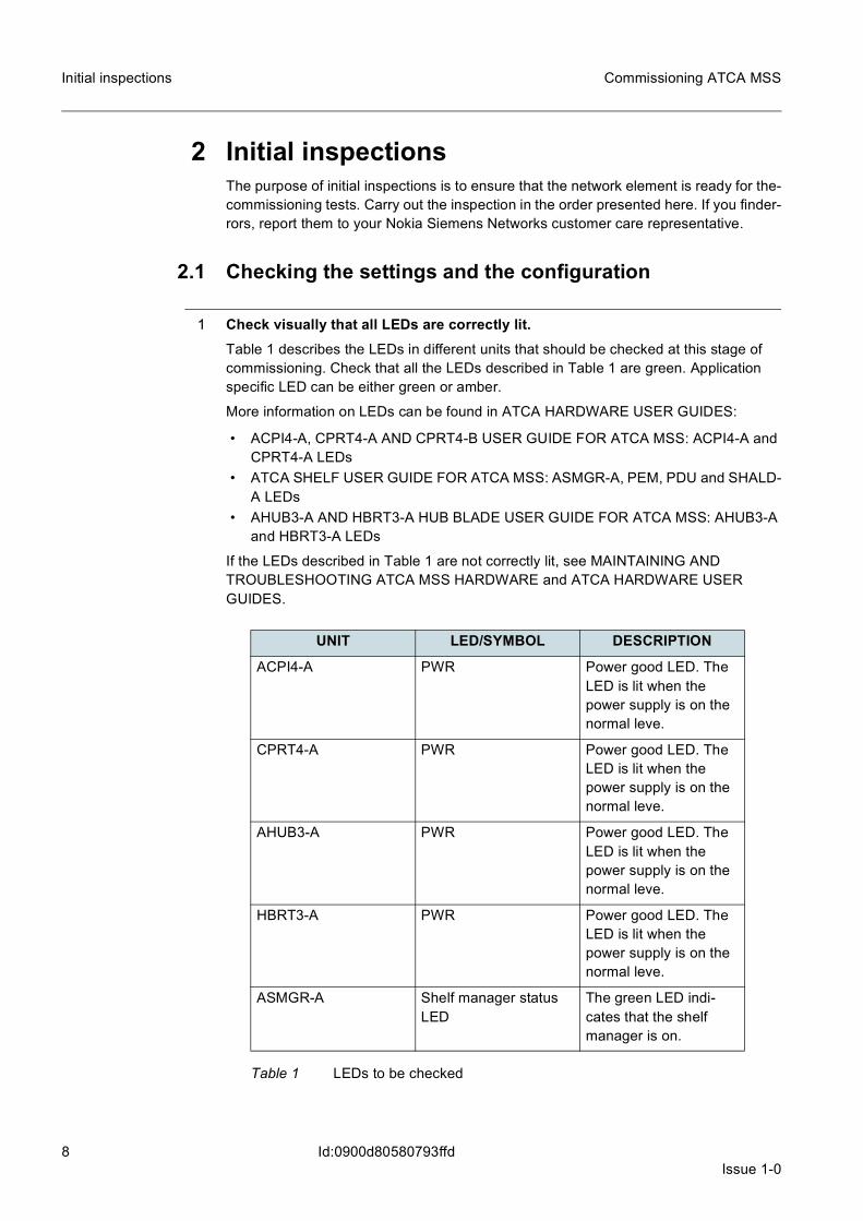
1 Check visually that all LEDs are correctly lit.Table 1 describes the LEDs in different units that should be checked at this stage of commissioning. Check that all the LEDs described in Table 1 are green. Application specific LED can be either green or amber.
More information on LEDs can be found in ATCA HARDWARE USER GUIDES:
• ACPI4-A, CPRT4-A AND CPRT4-B USER GUIDE FOR ATCA MSS: ACPI4-A and CPRT4-A LEDs
• ATCA SHELF USER GUIDE FOR ATCA MSS: ASMGR-A, PEM, PDU and SHALD-A LEDs
• AHUB3-A AND HBRT3-A HUB BLADE USER GUIDE FOR ATCA MSS: AHUB3-A and HBRT3-A LEDs
If the LEDs described in Table 1 are not correctly lit, see MAINTAINING AND TROUBLESHOOTING ATCA MSS HARDWARE and ATCA HARDWARE USER GUIDES.
UNIT LED/SYMBOL DESCRIPTION
ACPI4-A PWR Power good LED. The LED is lit when the power supply is on the normal leve.
CPRT4-A PWR Power good LED. The LED is lit when the power supply is on the normal leve.
AHUB3-A PWR Power good LED. The LED is lit when the power supply is on the normal leve.
HBRT3-A PWR Power good LED. The LED is lit when the power supply is on the normal leve.
ASMGR-A Shelf manager status LED
The green LED indi-cates that the shelf manager is on.
Table 1 LEDs to be checked

Issue 1-09
Commissioning ATCA MSS Initial inspections
Id:0900d80580793ffd
2 Check the functionality of the IPMI shelf managers.
a) Connect a serial cable from your workstation to the shelf manager’s serial port on the shelf alarm display.Communication parameters for connecting to the shelf manager (and to other units) from your workstation are the following: • Baud rate: 38,4 Kbs • Parity: None • Data bits: 8 • Stop bits: 1 The cable should be a null-modem cable and have an RJ-45 connector with the fol-lowing pinout:
b) Open a serial connection from you workstation to the shelf manager. You can use, for example, Hyperterminal in Windows workstations, or minicom in Linux.
c) Check that the login window is opened and that it is possible to log on to the shelf manager command line interface.
PEM PEM OK LED The green LED indi-cates that the system is healthy.
PDU Two alarm LEDs The green LEDs indicate that both branches of the PDU are healthy and that the PDU control part is healthy.
SHALD-A Three fan tray OK LEDs (left. center, right)
The green LEDs indicate that the fan trays are OK.
UNIT LED/SYMBOL DESCRIPTION
Table 1 LEDs to be checked (Cont.)
1 --
2 --
3 TXD
4 GND
5 GND
6 RXD
7 --
8 --
Table 2 Pinout of the RJ-45 connector

10Issue 1-0
Commissioning ATCA MSS
Id:0900d80580793ffd
Initial inspections
3 Log in to the shelf manager.The user name is root and the defaut password shmm4nsn.
For security reasons, it is advisable to change the password even though the shelf manager does not demand this.
# passwdChanging password for rootEnter the new password (minimum of 5, maximum of 8 characters)Please use a combination of upper and lower case letters and numbers.Enter new password: <new password>Re-enter new password: <new password>Password changed.
☞ The password for the user name root must be changed into the default password (shmm_root) before updating IPMI embedded software. After the update you can change the password back to the one you have chosen.
4 Check the minimum default fan speed in the shelf. Do the following check to all the shelf managers in the configuration. Note that each shelf has two shelf managers and you need to check both.
While connected to the shelf manager, give the command clia getfanlevel
Example output:
# clia getfanlevel fan_tray 1Pigeon Point Shelf Manager Command Line Interpreter20: FRU # 3 Override Fan Level: 7, Local Fan Level: 7# clia getfanlevel fan_tray 2Pigeon Point Shelf Manager Command Line Interpreter20: FRU # 4 Override Fan Level: 7, Local Fan Level: 7# clia getfanlevel fan_tray 3Pigeon Point Shelf Manager Command Line Interpreter20: FRU # 5 Override Fan Level: 7, Local Fan Level: 7#
The returned value indicates the minimum fan speed programmed into the system. If all the returned values for OVERRIDE FAN LEVEL and LOCAL FAN LEVEL are 7, the system is programmed correctly. If it is not, contact Nokia Siemens Networks.
5 Check that the Hot Swap State in every unit is M4 (Active).Give the command clia board in the shelf manager command line interface.
Example output: OMU unit in slot 1 (with CPRT4-A):
# clia board 1
PigeonPoint Shelf Manager Command Line Interpreter
Physical Slot # 19e: Entity: (0xa0, 0x60) Maximum FRU device ID: 0x02
PICMG Version 2.3

Issue 1-011
Commissioning ATCA MSS Initial inspections
Id:0900d80580793ffd
Hot Swap State: M4 (Active), Previous: M3 (Activation In Process), Last State Change Cause: Normal State Change (0x0)
9e: FRU # 0Entity: (0xa0, 0x60)Hot Swap State: M4 (Active), Previous: M3 (Activation In
Process), Last State Change Cause: Normal State Change (0x0)Device ID String: "ACPI4-A"
9e: FRU # 2
Entity: (0xc0, 0x60)Hot Swap State: M4 (Active), Previous: M3 (Activation In
Process), Last State Change Cause: Normal State Change (0x0)Device ID String: "CPRT4-A”
6 Check the shelf address.The shelf address is a 20-byte hexadecimal figure that uniquely identifies the shelf location in the cabinet and in the equipment room. The shelf address is stored in the PICMG address table in the shelf FRU information. You need to set this address during initial configuration.
☞ Shelf address must be the same as is configured in the equipment. Otherwise the CPUs do not boot up in that shelf.
a) Read the existing shelf addresses from the shelf with the command clia shelfaddress.Example output:# clia shelfaddressPigeon Point Shelf Manager Command Line Interpreter Shelf Address Info: "010001 A0101FFFFFF.."#
b) If the addresses are not correct, you can change them with command# clia shelfaddress "010001 A0101FFFFFF.." The address is given in quotation marks.Example output:# clia shelfaddressPigeon Point Shelf Manager Command Line InterpreterShelf Address Info: "0000FFFFFFFFFFFFFFFF.."## clia shelfaddress "010001 A0101FFFFFF.."Pigeon Point Shelf Manager Command Line InterpreterShelf Address info set successfully#
c) Compare this to the created configuration with MML command WTI.☞ For instructions o nhow to open the MML connectioin, see chapter OPENING
THE FIRST MML SESSION.Example output:MAIN LEVEL COMMAND <___>< WTI:CI;

12Issue 1-0
Commissioning ATCA MSS
Id:0900d80580793ffd
Initial inspections
EXECUTION STARTED
CART LOC SEN ITI-------- ---------------- ------------------ -------------ACH16_A 1A001-00 XY071300373 C110656....A1ACHAF2_A 1A001-00-FFI-01 XY071300467 C110639....A1A
TOTAL OF 2 CARTRIDGES
COMMAND EXECUTED
7 Clear the system event log.The System Event Log (SEL) stores all IPMI events and is stored in an EEPROM managed by the IPM controller. The SEL information is periodically sent to the system manager. You can read the local SEL through the system manager.
It is recommended to clear the SEL at this stage, as the installation of the system may have caused unnecessary logs. Those logs can disturb the detecting of the important logs later when the system is stable.The command sel clear clears the SEL on the specified IPM controller.Clear the SEL log by giving the command clia sel clear.Expected output:
# clia sel clear
Pigeon Point Shelf Manager Command Line Interpreter
SEL clear: issued successfullySEL clearing complete
8 Check the CPU blade BIOS settings.BIOS settings are configured in the factory, but if, for example, the positions of the CPU blades are changed, the BIOS settings should be verified. This is to ensure the correct boot device order in the CPU blade and the possibility to speed up the booting by dis-abling unnecessary initialization in the boot phase.
Check all the CPU blades of the configuration using the BIOS setup tool.
ACPI4-A BIOS SETTINGSCommunication parameters via serial port COM1 in ACPI4-A are the following:
• Baud rate: 38.4 Kbs • Data bits: 8 • Parity: None • Stop bits: 1 • Flow control: None • Terminal type: ANSI • Terminal display mode: Normal mode • BIOS printouts: Enabled
Issue 1-013
Commissioning ATCA MSS Initial inspections
Id:0900d80580793ffd
You can access the BIOS setup tool by pressing F2 in the boot phase. In some terminal programs Function keys cannot be used as it is usually assigned to some windows-control. In that case use ESC-2 key combination. You can also use F4 or DEL keys for accessing BIOS.
More detailed infromation can be found in ACPI4-A, CPRT4-A AND CPRT4-B USER GUIDE FOR ATCA MSS.
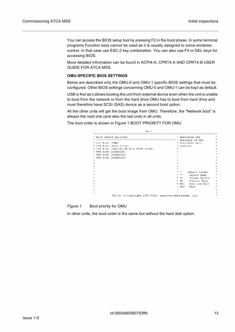
OMU-SPECIFIC BIOS SETTINGSBelow are described only the OMU-0 and OMU-1 specific BIOS settings that must be configured. Other BIOS settings concerning OMU-0 and OMU-1 can be kept as default.
USB is first as it allows booting the unit from external device even when the unit is unable to boot from the network or from the hard drive.OMU has to boot from hard drive and must therefore have SCSI (SAS) device as a second boot option.
All the other units will get the boot image from OMU. Therefore, the "Network boot" is always the next one (and also the last one) in all units.
The boot order is shown in Figure 1 BOOT PRIORITY FOR OMU.
Figure 1 Boot priority for OMU
In other units, the boot order is the same but without the hard disk option.

14Issue 1-0
Commissioning ATCA MSS
Id:0900d80580793ffd
Initial inspections
Figure 2 Boot priority in other than OMU units
BIOS SETTINGS OF OMU UNITSOMU units have an RTM Expansion ROM option enabled in the Advanced menu.
Figure 3 Advanced options for OMU
BIOS SETTINGS OF VMU UNITSFor virtualized unit some HW virtualization parameters need to be set. Other BIOS settings concerning other functional units can be kept as default.

Issue 1-015
Commissioning ATCA MSS Initial inspections
Id:0900d80580793ffd
Figure 4 IO-SRV activation
Figure 5 VT-d activation
BIOS SETTINGS OF ALL DMX UNITSACPI4-A uses cold restart by default. To enable warm restarts on DMX units, the follow-ing changes need to be done in the Boot settings menu.
• Default reset type: Warm reset • Warm reset initial count: 5

16Issue 1-0
Commissioning ATCA MSS
Id:0900d80580793ffd
Initial inspections
Figure 6 Setting up warm restart
9 Check if the service terminal interface of AHUB3-A works and run AHUB self test.Connect a serial cable from your workstation to the serial port LMP SER on the AHUB3-A blade front panel.

Issue 1-017
Commissioning ATCA MSS Initial inspections
Id:0900d80580793ffd
Figure 7 AHUB3-A front panel
Establish a session with the unit. Enter your password, which is nsn--hub by default. The device name prompt is displayed.
10 Check the AHUB3-A configuration used for EMB (BI serial port)Use the command show interface in the service terminal connected to the AHUB3-A for EMB use.
From the service terminal session, start Base Ethernet.
AHUB3-A
LMP
SER
Not in use
COM-E ETH
LMP
ETH
Not in use
COM-E USB
XFP 1/1
XFP 1/2
XFP 1/3
XFP 1/5
Link
Port
Link
Port
Link
Port
Link
Port
AP
P
Link
PortSFP 1/6
Link
PortSFP 1/7
Link
PortSFP 1/8
Link
PortSFP 1/9
Reset
CLASS 1 LASER PRODUCT
IEC/EN 60825-1
DN0936733
Not in use
COM-E SER
FABRIC
BASE
18Issue 1-0
Commissioning ATCA MSS
Id:0900d80580793ffd
Initial inspections
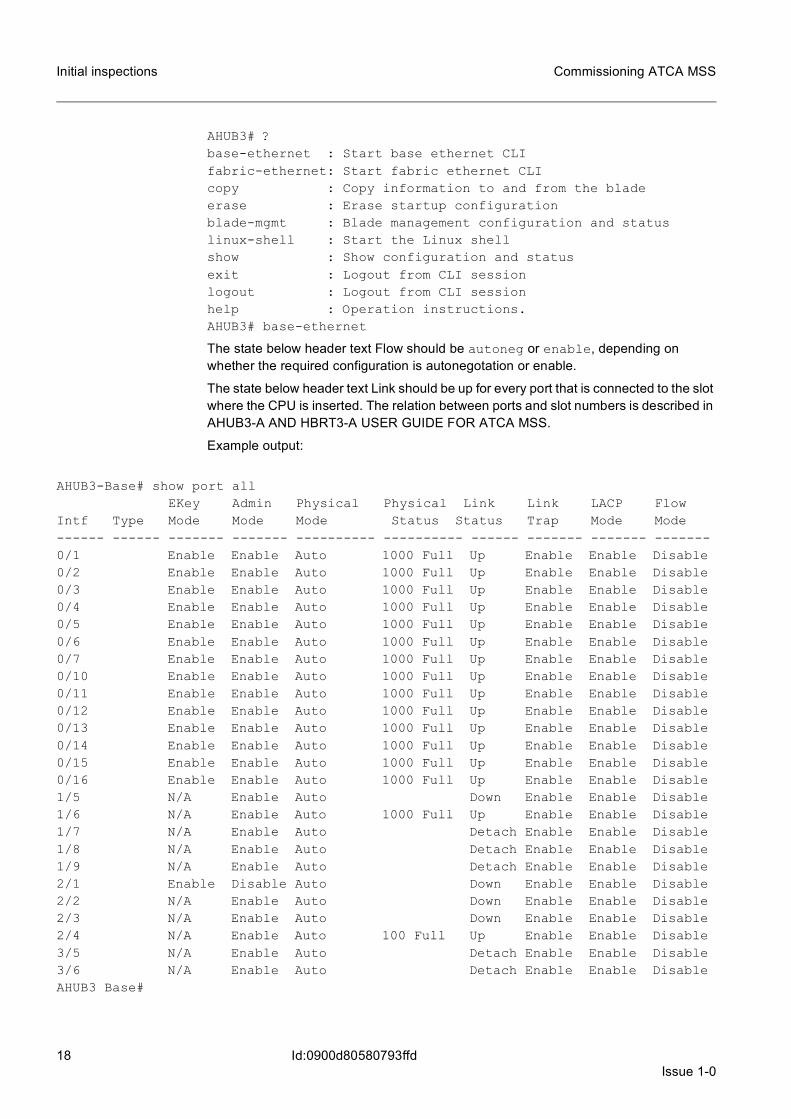
AHUB3# ?base-ethernet : Start base ethernet CLIfabric-ethernet: Start fabric ethernet CLIcopy : Copy information to and from the bladeerase : Erase startup configurationblade-mgmt : Blade management configuration and statuslinux-shell : Start the Linux shellshow : Show configuration and statusexit : Logout from CLI sessionlogout : Logout from CLI sessionhelp : Operation instructions.AHUB3# base-ethernet
The state below header text Flow should be autoneg or enable, depending on whether the required configuration is autonegotation or enable.
The state below header text Link should be up for every port that is connected to the slot where the CPU is inserted. The relation between ports and slot numbers is described in AHUB3-A AND HBRT3-A USER GUIDE FOR ATCA MSS.
Example output:
AHUB3-Base# show port allEKey Admin Physical Physical Link Link LACP Flow
Intf Type Mode Mode Mode Status Status Trap Mode Mode------ ------ ------- ------- ---------- ---------- ------ ------- ------- -------0/1 Enable Enable Auto 1000 Full Up Enable Enable Disable 0/2 Enable Enable Auto 1000 Full Up Enable Enable Disable 0/3 Enable Enable Auto 1000 Full Up Enable Enable Disable 0/4 Enable Enable Auto 1000 Full Up Enable Enable Disable 0/5 Enable Enable Auto 1000 Full Up Enable Enable Disable 0/6 Enable Enable Auto 1000 Full Up Enable Enable Disable 0/7 Enable Enable Auto 1000 Full Up Enable Enable Disable 0/10 Enable Enable Auto 1000 Full Up Enable Enable Disable 0/11 Enable Enable Auto 1000 Full Up Enable Enable Disable 0/12 Enable Enable Auto 1000 Full Up Enable Enable Disable 0/13 Enable Enable Auto 1000 Full Up Enable Enable Disable 0/14 Enable Enable Auto 1000 Full Up Enable Enable Disable 0/15 Enable Enable Auto 1000 Full Up Enable Enable Disable 0/16 Enable Enable Auto 1000 Full Up Enable Enable Disable 1/5 N/A Enable Auto Down Enable Enable Disable 1/6 N/A Enable Auto 1000 Full Up Enable Enable Disable 1/7 N/A Enable Auto Detach Enable Enable Disable 1/8 N/A Enable Auto Detach Enable Enable Disable 1/9 N/A Enable Auto Detach Enable Enable Disable 2/1 Enable Disable Auto Down Enable Enable Disable 2/2 N/A Enable Auto Down Enable Enable Disable 2/3 N/A Enable Auto Down Enable Enable Disable 2/4 N/A Enable Auto 100 Full Up Enable Enable Disable 3/5 N/A Enable Auto Detach Enable Enable Disable 3/6 N/A Enable Auto Detach Enable Enable Disable AHUB3 Base#

Issue 1-019
Commissioning ATCA MSS Initial inspections
Id:0900d80580793ffd
2.2 Inspecting the storage devices
1 Log in to the OMUs and CHUs one by one and execute step 2 and step 3 on each unit.
2 Check that the disk can be read.Use the following service terminal command to display SAS device information:
00-MAN> ZQM:W0
00-MAN> ZQM:W1
The output should show the product information of the hard disks:
VENDOR IDENTIFICATION : FUJITSUPRODUCT IDENTIFICATION : MAY2073RCPRODUCT REVISION : 0103
3 Check that the disk units have been initialized.00-MAN>ZMX:W0
00-MAN>ZMX:W1
The root directory of the disk should be displayed, indicating that the file system has been initialized.
2.3 Creating a bootable USB stick and copying a minidebug-ger to itA bootable USB stick can serve as a backup in case of total failure of both hard disks, when new hard disks without proper software build has to be taken in use.
Connect first the USB stick to the USB port in the front panel of the active OMU. (The USB stick can be accessed only if it is connected to the active OMU.)
When the USB stick is connected, the working state of the UMS-0 will change into WO state automatically. You can check the state with the MML command ISI.
☞ For instructions on how to open the MML connection, see OPENING THE FIRST MML SESSION.
To ensure that the USB sticks function properly, use only sticks that conform to the USB 2.0 standard and have no special features such as security features. The rec-ommended brands are Sandisk and Kingston.
When taking a new disk in use, format and initialize it via a service terminal. There are two possibilities:
• To create a bootable USB media with minidebugger, use the FAT16 file system. This restricts the USB capacity to 2GB. If you want a bootable USB stick, the size of the stick should be 512 MB - 2 GB.
• To create a USB media with more than the capacity of 2GB, use the FAT32 filesys-tem. In this case the USB media cannot be used as a boot device even if there is a minidebugger build copied to it.
20Issue 1-0
Commissioning ATCA MSS
Id:0900d80580793ffd
Initial inspections
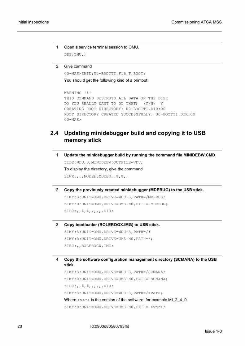
1 Open a service terminal session to OMU.
DDS:OMU,;
2 Give command
00-MAS>ZMID:U0-BOOTTI,F16,T,BOOT;
You should get the following kind of a printout:
WARNING !!!THIS COMMAND DESTROYS ALL DATA ON THE DISKDO YOU REALLY WANT TO DO THAT? (Y/N) YCREATING ROOT DIRECTORY: U0-BOOTTI.DIR:00ROOT DIRECTORY CREATED SUCCESSFULLY: U0-BOOTTI.DIR:0000-MAS>
2.4 Updating minidebugger build and copying it to USB memory stick
1 Update the minidebugger build by running the command file MINIDEBW.CMD ZIDE:WDU,0,MINIDEBW:OUTFILE=VDU;
To display the directory, give the command
ZIWX:,:,NODEF:MDEBU,:%,%,;
2 Copy the previously created minidebugger (MDEBUG) to the USB stick.ZIWY:S:UNIT=OMU,DRIVE=WDU-S,PATH=/MDEBUG;
ZIWY:D:UNIT=OMU,DRIVE=UMS-N0,PATH=-MDEBUG;
ZIBC:,,%,%,,,,,,DIR;
3 Copy bootloader (BOLEROGX.IMG) to USB stick.ZIWY:S:UNIT=OMU,DRIVE=WDU-S,PATH=/;
ZIWY:D:UNIT=OMU,DRIVE=UMS-N0,PATH=/;
ZIBC:,,BOLEROGX,IMG;
4 Copy the software configuration management directory (SCMANA) to the USB stick.ZIWY:S:UNIT=OMU,DRIVE=WDU-S,PATH=/SCMANA;
ZIWY:D:UNIT=OMU,DRIVE=UMS-N0,PATH=-SCMANA;
ZIBC:,,%,%,,,,,,DIR;
ZIWY:S:UNIT=OMU,DRIVE=WDU-S,PATH=/<ver>;
Where <ver> is the version of the software, for example MI_2_4_0.
ZIWY:D:UNIT=OMU,DRIVE=UMS-N0,PATH=-<ver>;

Issue 1-021
Commissioning ATCA MSS Initial inspections
Id:0900d80580793ffd
ZIBC:,,%,%,,,,,,DIR;
22Issue 1-0
Commissioning ATCA MSS
Id:0900d8058079b1ff
Opening the first MML session
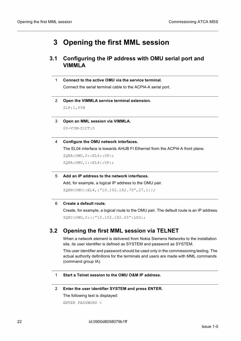
3 Opening the first MML session
3.1 Configuring the IP address with OMU serial port and VIMMLA
1 Connect to the active OMU via the service terminal.Connect the serial terminal cable to the ACPI4-A serial port.
2 Open the VIMMLA service terminal extension.ZLP:1,VIM
3 Open an MML session via VIMMLA.00-VIM>Z1CT:0
4 Configure the OMU network interfaces.The EL04 interface is towards AHUB FI Ethernet from the ACPI4-A front plane.
ZQRA:OMU,0::EL4::UP:;
ZQRA:OMU,1::EL4::UP:;
5 Add an IP address to the network interfaces.Add, for example, a logical IP address to the OMU pair.
ZQRN:OMU::EL4,:”10.102.182.70”,27,l::;
6 Create a default route.Create, for example, a logical route to the OMU pair. The default route is an IP address.
ZQKC:OMU,0:::”10.102.182.65”:LOG:;
3.2 Opening the first MML session via TELNETWhen a network element is delivered from Nokia Siemens Networks to the installation site, its user identifier is defined as SYSTEM and password as SYSTEM.
This user identifier and password should be used only in the commissioning testing. The actual authority definitions for the terminals and users are made with MML commands (command group IA).
1 Start a Telnet session to the OMU O&M IP address.
2 Enter the user identifier SYSTEM and press ENTER.The following text is displayed:
ENTER PASSWORD <
Issue 1-023
Commissioning ATCA MSS Opening the first MML session
Id:0900d8058079b1ff
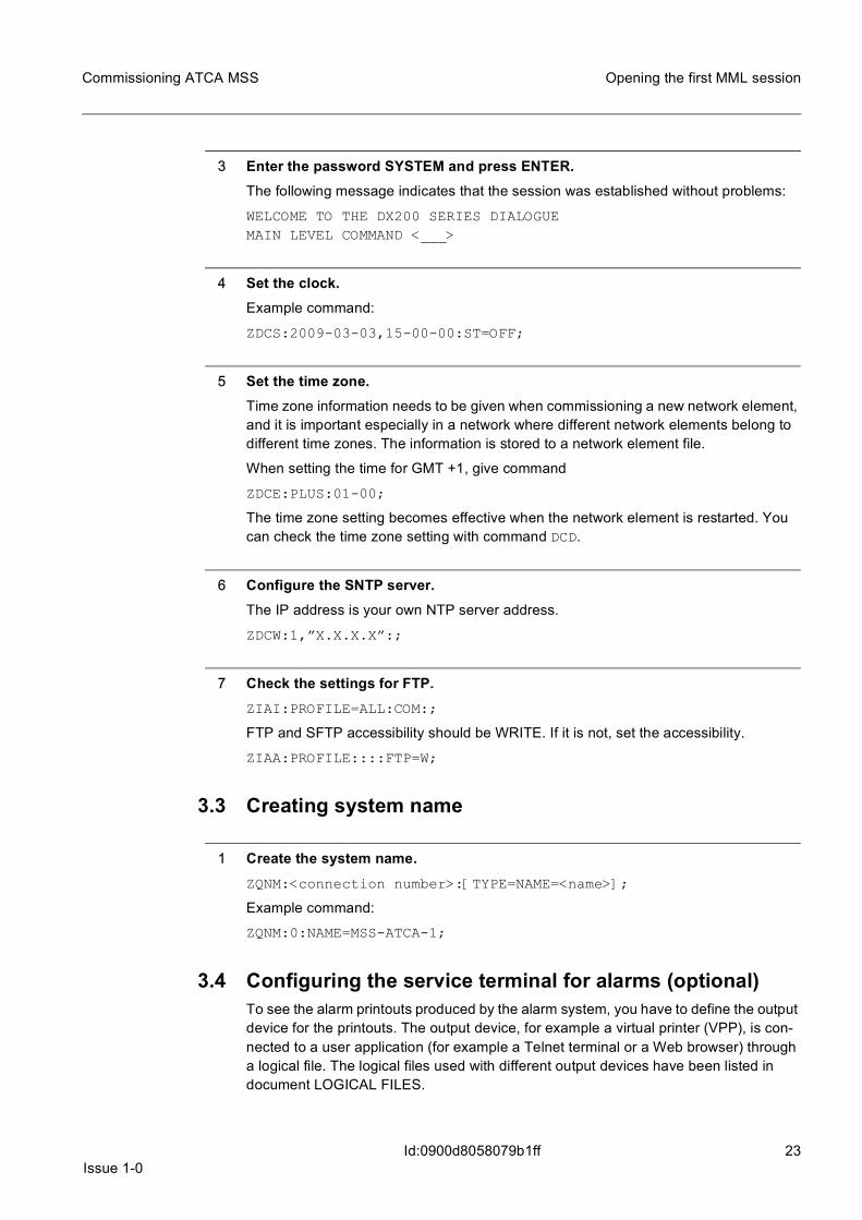
3 Enter the password SYSTEM and press ENTER.The following message indicates that the session was established without problems:
WELCOME TO THE DX200 SERIES DIALOGUEMAIN LEVEL COMMAND <___>
4 Set the clock.Example command:
ZDCS:2009-03-03,15-00-00:ST=OFF;
5 Set the time zone.Time zone information needs to be given when commissioning a new network element, and it is important especially in a network where different network elements belong to different time zones. The information is stored to a network element file.
When setting the time for GMT +1, give command
ZDCE:PLUS:01-00;
The time zone setting becomes effective when the network element is restarted. You can check the time zone setting with command DCD.
6 Configure the SNTP server.The IP address is your own NTP server address.
ZDCW:1,”X.X.X.X”:;
7 Check the settings for FTP.ZIAI:PROFILE=ALL:COM:;
FTP and SFTP accessibility should be WRITE. If it is not, set the accessibility.
ZIAA:PROFILE::::FTP=W;
3.3 Creating system name
1 Create the system name.ZQNM:<connection number>:[TYPE=NAME=<name>];
Example command:
ZQNM:0:NAME=MSS-ATCA-1;
3.4 Configuring the service terminal for alarms (optional)To see the alarm printouts produced by the alarm system, you have to define the output device for the printouts. The output device, for example a virtual printer (VPP), is con-nected to a user application (for example a Telnet terminal or a Web browser) through a logical file. The logical files used with different output devices have been listed in document LOGICAL FILES.

24Issue 1-0
Commissioning ATCA MSS
Id:0900d8058079b1ff
Opening the first MML session
1 Check that the IP address of the computer unit has been defined.ZQRI;
2 Check that the logical files used to print out alarms have been connected to the correct VPP devices.Check the connection between each logical file and VPP device you are going to use for alarm printing.
ZIID::<logical file name>,:;
If all the logical files are connected at least to VPP-99, continue from step 4.
If the logical files are not connected to VPP-99, VPP-98, VPP-96 or VPP-95, continue from step 3.
☞ If all logical files are connected to VPP-99, one remote session for alarm printing can be established.
If the logical files are connected to two VPPs, for example VPP-99 and VPP-98, two simultaneous sessions can be established. In this case, VPP-99 serves the first con-nection, VPP-98 the second connection, and so forth.
3 Connect the logical files to the correct VPP devices.If you want to print out all the alarms to the same window, connect VPP-99 to every alarm-related logical file.
If you want to print out only certain alarms, for example, two-star and three-star alarms, connect the logical files used with these alarms to the correct VPP devices. For files that can be used for these printouts, check the LOGICAL FILES document.
If you want to replace an existing I/O device with a new one, use the parameter IND=<current object index>. If this parameter is not given, the new I/O device is simply added but does not replace the previous I/O device.
ZIIS::<logical file name>::DEV=VPP-<I/O device index>;
ZIIS::<logical file name>:IND=<current object index>:DEV=VPP-<I/O device index>;
After connecting the logical files associated with alarms to the correct devices, you do not need to change these connections during the lifetime of the software build. You can now print out alarms as described in step 4.
4 Establish a Telnet or HTTP connection to the OMU IP address, port 11111.If you are using a Telnet terminal, press the Enter key once, after you have connected to the correct address and port.
If you are using a Web browser, connect to the correct address and port, no extra key-strokes are needed.
Expected outcomeThe alarms occurring in the network element are displayed on the Telnet terminal or Web browser.

Issue 1-025
Commissioning ATCA MSS Opening the first MML session
Id:0900d8058079b1ff
5 Check the state of the corresponding VPP devices.The connection for alarm printing is established, if the working state of the VPP devices corresponding to the Telnet or HTTP sessions is WO-EX.
The working state of the VPP devices not reserved for any connection is BL-EX.
ZISI::VPP;
In either of the following cases, alarms will not be printed via Telnet/HTTP:
• The VPP device which you connected to is not in the WO-EX state. • The connection for alarm printing is not established, or it is disconnected.
To re-establish the connection for alarm printing via Telnet or HTTP, start a new con-nection to OMU, port 11111 from a Telnet terminal or Web browser.
6 When you are ready, end the session.You can stop printing alarms via Telnet or HTTP by closing the Telnet terminal or the Web browser.

26Issue 1-0
Commissioning ATCA MSS
Id:0900d8058079b50f
Checking the start-up
4 Checking the start-upThe start-up of the whole system depends on the start-up priorities of the system units. A unit with higher priority is given loading permission before a unit with lower priority.
Within the system, the units are started up according to their respective priorities. Units with the same priority are given permission to load simultaneously.
In case of double units, the working units are given loading permission first, before the spare units. The different units are started up partly simultaneously. For example, when the OMU units have been loaded up to certain point, the CMM units are given loading permission.
The start-up order of the whole system is as follows:
1. OMU2. CMM3. CHU4. VMU5. IPDU6. Virtualized units
4.1 Monitoring the start-up of the unitsThe failure of the OMU to start-up can lead to a similar failure in all the other units. The working state of the OMU should be WO-EX during the start-up of the system. If the OMU-0 is in the TE or SE state, the maintenance programs will be started up in the OMU-1.
1 Open the service terminal connection to the WO OMU.Monitor the start-up of the units via the RCBUGG extension.
ZLE:U,RCBUGGGX
The RCBUGG is taken into use.
ZUSIC:ALL
2 Wait until all the units are in the WO-EX or SP-EX state.
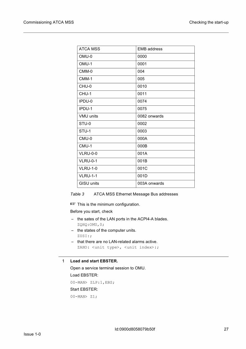
4.2 Inspecting the EMB connectionsThe purpose of this phase is inspection of the Ethernet Message Bus (EMB). The EMB LAN connections are tested by sending a test message from each computer unit to all other untis. The purpose of this is to ensure that all the computer units can be reached both through EMB-0 and EMB-1.
The tests are executed with the commands of the EBSTER service terminal extension. EBSTER sends the test message through the MB to the post offices of the computer units, and the post offices acknowledge the message through the EMB. The test is run separately for EMB-0 and EMB-1.
Issue 1-027
Commissioning ATCA MSS Checking the start-up
Id:0900d8058079b50f
☞ This is the minimum configuration.
Before you start, check
– the sates of the LAN ports in the ACPI4-A blades.ZQHQ:OMU,0;
– the states of the computer units.ZUSI:;
– that there are no LAN-related alarms active.ZAHO: <unit type>, <unit index>:;
1 Load and start EBSTER.Open a service terminal session to OMU.
Load EBSTER:
00-MAN> ZLP:1,EBS;
Start EBSTER:
00-MAN> Z1;
ATCA MSS EMB address
OMU-0 0000
OMU-1 0001
CMM-0 004
CMM-1 005
CHU-0 0010
CHU-1 0011
IPDU-0 0074
IPDU-1 0075
VMU units 0082 onwards
STU-0 0002
STU-1 0003
CMU-0 000A
CMU-1 000B
VLRU-0-0 001A
VLRU-0-1 001B
VLRU-1-0 001C
VLRU-1-1 001D
GISU units 003A onwards
Table 3 ATCA MSS Ethernet Message Bus addresses
28Issue 1-0
Commissioning ATCA MSS
Id:0900d8058079b50f
Checking the start-up
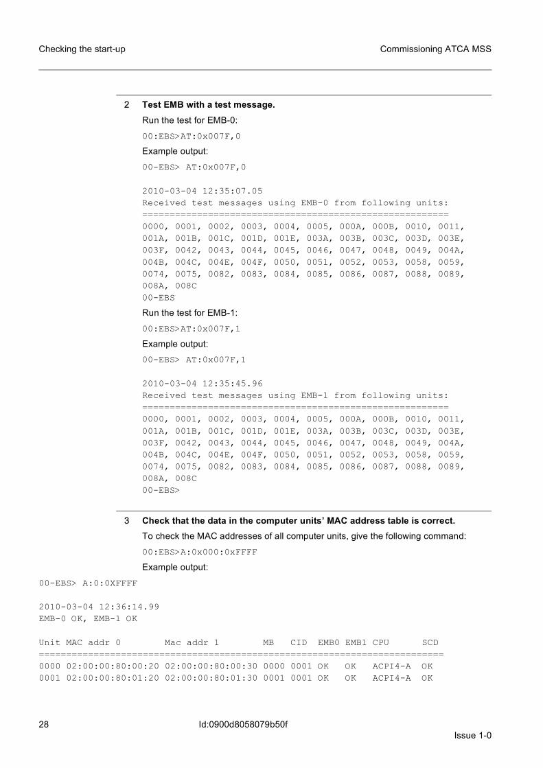
2 Test EMB with a test message.Run the test for EMB-0:
00:EBS>AT:0x007F,0
Example output:
00-EBS> AT:0x007F,0
2010-03-04 12:35:07.05Received test messages using EMB-0 from following units:========================================================0000, 0001, 0002, 0003, 0004, 0005, 000A, 000B, 0010, 0011, 001A, 001B, 001C, 001D, 001E, 003A, 003B, 003C, 003D, 003E, 003F, 0042, 0043, 0044, 0045, 0046, 0047, 0048, 0049, 004A, 004B, 004C, 004E, 004F, 0050, 0051, 0052, 0053, 0058, 0059, 0074, 0075, 0082, 0083, 0084, 0085, 0086, 0087, 0088, 0089, 008A, 008C00-EBS
Run the test for EMB-1:
00:EBS>AT:0x007F,1
Example output:
00-EBS> AT:0x007F,1
2010-03-04 12:35:45.96Received test messages using EMB-1 from following units:========================================================0000, 0001, 0002, 0003, 0004, 0005, 000A, 000B, 0010, 0011, 001A, 001B, 001C, 001D, 001E, 003A, 003B, 003C, 003D, 003E, 003F, 0042, 0043, 0044, 0045, 0046, 0047, 0048, 0049, 004A, 004B, 004C, 004E, 004F, 0050, 0051, 0052, 0053, 0058, 0059, 0074, 0075, 0082, 0083, 0084, 0085, 0086, 0087, 0088, 0089, 008A, 008C00-EBS>
3 Check that the data in the computer units’ MAC address table is correct.To check the MAC addresses of all computer units, give the following command:
00:EBS>A:0x000:0xFFFF
Example output:
00-EBS> A:0:0XFFFF
2010-03-04 12:36:14.99EMB-0 OK, EMB-1 OK
Unit MAC addr 0 Mac addr 1 MB CID EMB0 EMB1 CPU SCD==========================================================================0000 02:00:00:80:00:20 02:00:00:80:00:30 0000 0001 OK OK ACPI4-A OK0001 02:00:00:80:01:20 02:00:00:80:01:30 0001 0001 OK OK ACPI4-A OK

Issue 1-029
Commissioning ATCA MSS Checking the start-up
Id:0900d8058079b50f
0002 02:00:00:80:02:20 02:00:00:80:02:30 0002 0002 OK OK CPVC OK0003 02:00:00:80:03:20 02:00:00:80:03:30 0003 0003 OK OK CPVC OK0004 02:00:00:80:04:20 02:00:00:80:04:30 0004 0004 OK OK ACPI4-A OK0005 02:00:00:80:05:20 02:00:00:80:05:30 0005 0005 OK OK ACPI4-A OK000A 02:00:00:80:0A:20 02:00:00:80:0A:30 000A 000A OK OK CPVC OK000B 02:00:00:80:0B:20 02:00:00:80:0B:30 000B 0001 OK OK CPVC OK0010 02:00:00:80:10:20 02:00:00:80:10:30 0010 0010 OK OK ACPI4-A OK0011 02:00:00:80:11:20 02:00:00:80:11:30 0011 0011 OK OK ACPI4-A OK001A 02:00:00:80:1A:20 02:00:00:80:1A:30 001A 001A OK OK CPVC OK001B 02:00:00:80:1B:20 02:00:00:80:1B:30 001B 001B OK OK CPVC OK...0087 02:00:00:80:87:20 02:00:00:80:87:30 0087 0087 OK OK ACPI4-A OK0088 02:00:00:80:88:20 02:00:00:80:88:30 0088 0088 OK OK ACPI4-A OK0089 02:00:00:80:89:20 02:00:00:80:89:30 0089 0089 OK OK ACPI4-A OK008A 02:00:00:80:8A:20 02:00:00:80:8A:30 008A 008A OK OK ACPI4-A OK008C 02:00:00:80:8C:20 02:00:00:80:8C:30 008C 008C OK OK ACPI4-A OK
EMB-connections to following units not working=========================================================================
00-EBS
From the printout, check
• that all computer units have been listed. • that there are two MAC addresses for each computer. • that both EMB0 and EMB1 are OK for all units and no units are listed at the end of
the execution print-out.
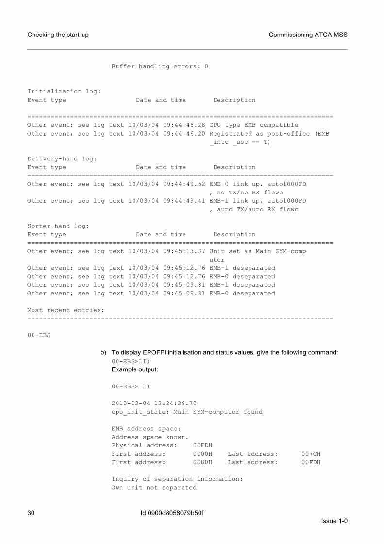
4 Check the error logs
a) To display the EPOFFI internal log using routine call, give the following command:42:EBS>LExample output:00-EBS> L
2010-03-04 13:22:09.81EPOFFI's Internal log counters:Initialization errors: 0ETHLIB out of resources: 0Sending errors: 0Receiving errors: 0Ethernet link down: 0Resend reqests: 0TX flow control sends: 0RX flow control sends: 0Invalid messages: 0Invalid frames: 0Out of memory : 0Out of buffers: 0
30Issue 1-0
Commissioning ATCA MSS
Id:0900d8058079b50f
Checking the start-up
Buffer handling errors: 0
Initialization log:Event type Date and time Description
===============================================================================Other event; see log text 10/03/04 09:44:46.28 CPU type EMB compatibleOther event; see log text 10/03/04 09:44:46.20 Registrated as post-office (EMB
_into _use == T)
Delivery-hand log:Event type Date and time Description===============================================================================Other event; see log text 10/03/04 09:44:49.52 EMB-0 link up, auto1000FD
, no TX/no RX flowcOther event; see log text 10/03/04 09:44:49.41 EMB-1 link up, auto1000FD
, auto TX/auto RX flowc
Sorter-hand log:Event type Date and time Description===============================================================================Other event; see log text 10/03/04 09:45:13.37 Unit set as Main SYM-comp
uterOther event; see log text 10/03/04 09:45:12.76 EMB-1 deseparatedOther event; see log text 10/03/04 09:45:12.76 EMB-0 deseparatedOther event; see log text 10/03/04 09:45:09.81 EMB-1 deseparatedOther event; see log text 10/03/04 09:45:09.81 EMB-0 deseparated
Most recent entries:-------------------------------------------------------------------------------
00-EBS
b) To display EPOFFI initialisation and status values, give the following command:00-EBS>LI;Example output:
00-EBS> LI
2010-03-04 13:24:39.70epo_init_state: Main SYM-computer found
EMB address space:Address space known.Physical address: 00FDHFirst address: 0000H Last address: 007CHFirst address: 0080H Last address: 00FDH
Inquiry of separation information:Own unit not separated

Issue 1-031
Commissioning ATCA MSS Checking the start-up
Id:0900d8058079b50f
EMB-0: interface not separated, lan existsEMB-1: interface not separated, lan exists
00-EBS
5 Exit and unload EBSTER.To exit the session:
Z;
To unload EBSTER:
ZL:1;

32Issue 1-0
Commissioning ATCA MSS
Id:0900d8058079b61b
Inspecting ATCA MSS software versions
5 Inspecting ATCA MSS software versions
5.1 Inspecting software versionsThe purpose of this phase is to ensure that:
– you are using the correct software version by comparing them to the RELEASE DOCUMENTATION
– the software modules contain flawless data
Before you start, make sure that you have all the necessary change notes available.
1 Check the software package.Verify that the correct software package is on the hard disks and also loaded for every unit needed.
ZWQO::;
Example output:
SOFTWARE PACKAGE ADMINISTRATION COMMAND <WQ_>< ZWQO;
LOADING PROGRAM VERSION 14.9-1EXISTING PACKAGES ON OMU WDU-0:-------------------------------SW-PACKAGE STATUS DIRECTORY ENVIRONMENT
PACKAGE-ID (REP-ID) DELIVERYCD-ID
MI220 BU MI_2_2_0 MG 2.2-0MG 2.2-0 CIDPRDMI 2.6-0
MI240 NW MI_2_4_0 MG 2.4-0MG 2.4-0 CIDPRDMI 2.7-0
EXISTING PACKAGES ON OMU WDU-1:-------------------------------SW-PACKAGE STATUS DIRECTORY ENVIRONMENT
PACKAGE-ID (REP-ID) DELIVERYCD-ID
MI220 BU MI_2_2_0 MG 2.2-0MG 2.2-0 CIDPRDMI 2.6-0
MI240 NW MI_2_4_0 MG 2.4-0MG 2.4-0 CIDPRDMI 2.7-0
DISK SPACE IN OMU:IN WDU-0 FREE 243946405 BLOCKS OF 286749488IN WDU-1 FREE 247986271 BLOCKS OF 286749488
Issue 1-033
Commissioning ATCA MSS Inspecting ATCA MSS software versions
Id:0900d8058079b61b
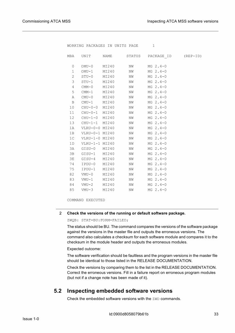
WORKING PACKAGES IN UNITS PAGE 1
MBA UNIT NAME STATUS PACKAGE_ID (REP-ID)
0 OMU-0 MI240 NW MG 2.4-01 OMU-1 MI240 NW MG 2.4-02 STU-0 MI240 NW MG 2.4-03 STU-1 MI240 NW MG 2.4-04 CMM-0 MI240 NW MG 2.4-05 CMM-1 MI240 NW MG 2.4-0A CMU-0 MI240 NW MG 2.4-0B CMU-1 MI240 NW MG 2.4-0
10 CHU-0-0 MI240 NW MG 2.4-011 CHU-0-1 MI240 NW MG 2.4-012 CHU-1-0 MI240 NW MG 2.4-013 CHU-1-1 MI240 NW MG 2.4-01A VLRU-0-0 MI240 NW MG 2.4-01B VLRU-0-1 MI240 NW MG 2.4-01C VLRU-1-0 MI240 NW MG 2.4-01D VLRU-1-1 MI240 NW MG 2.4-03A GISU-0 MI240 NW MG 2.4-03B GISU-1 MI240 NW MG 2.4-03E GISU-4 MI240 NW MG 2.4-074 IPDU-0 MI240 NW MG 2.4-075 IPDU-1 MI240 NW MG 2.4-082 VMU-0 MI240 NW MG 2.4-083 VMU-1 MI240 NW MG 2.4-084 VMU-2 MI240 NW MG 2.4-085 VMU-3 MI240 NW MG 2.4-0
COMMAND EXECUTED
2 Check the versions of the running or default software package.ZWQB: STAT=BU:FORM=FAILED;
The status should be BU. The command compares the versions of the software package against the versions in the master file and outputs the erroneous versions. The command also calculates a checksum for each software module and compares it to the checksum in the module header and outputs the erroneous modules.
Expected outcome:
The software verification should be faultless and the program versions in the master file should be identical to those listed in the RELEASE DOCUMENTATION.
Check the versions by comparing them to the list in the RELEASE DOCUMENTATION. Correct the erroneous versions. Fill in a failure report on erroneous program modules (but not if a change note has been made of it).
5.2 Inspecting embedded software versionsCheck the embedded software versions with the ZWD commands.

34Issue 1-0
Commissioning ATCA MSS
Id:0900d8058079b61b
Inspecting ATCA MSS software versions
1 Check the versions of HPM.1.All ACPI4-A embedded software is collected to one HPM.1 file, which can be updated to the CPU.
ZWDN;
Example output:
MAIN LEVEL COMMAND <___>< ZWDN;
LOADING PROGRAM VERSION 11.1-0
EXECUTION STARTED
18 VALID PLUG-IN UNITS FOUND
EXECUTION STARTED AT 2010-03-05 15:22:535% DONE, PLEASE WAIT 0 H, 9 MIN AND 59 SEC
11% DONE, PLEASE WAIT 0 H, 9 MIN AND 58 SEC16% DONE, PLEASE WAIT 0 H, 9 MIN AND 57 SEC... 94% DONE, PLEASE WAIT 0 H, 9 MIN AND 44 SEC
100% DONE, PLEASE WAIT 0 H, 0 MIN AND 0 SEC
FUNCTIONAL PLUG-IN UNIT VERSIONUNIT TYPE INDEX CURRENT -> AFTER UPDATE------- ----------- ------------------------------OMU-0 ACPI4_A-0 acpi4-a_kn_ipmc_05.52.4846 ->
acpi4-a_kn_ipmc_05.52.4846 RABESW3_0950OMU-1 ACPI4_A-0 acpi4-a_kn_ipmc_05.52.4846 ->
acpi4-a_kn_ipmc_05.52.4846 RABESW3_0950...
acpi4-a_kn_ipmc_05.52.4846 RABESW3_0950VMU-7 ACPI4_A-0 acpi4-a_kn_ipmc_05.52.4846 ->
acpi4-a_kn_ipmc_05.52.4846 RABESW3_0950VMU-8 ACPI4_A-0 acpi4-a_kn_ipmc_05.52.4846 ->
acpi4-a_kn_ipmc_05.52.4846 RABESW3_0950VMU-10 ACPI4_A-0 acpi4-a_kn_ipmc_05.52.4846 ->
acpi4-a_kn_ipmc_05.52.4846 RABESW3_0950IPDU-0 ACPI4_A-0 acpi4-a_kn_ipmc_05.52.4846 ->
acpi4-a_kn_ipmc_05.52.4846 RABESW3_0950IPDU-1 ACPI4_A-0 acpi4-a_kn_ipmc_05.52.4846 ->
acpi4-a_kn_ipmc_05.52.4846 RABESW3_0950
COMMAND EXECUTED

Issue 1-035
Commissioning ATCA MSS Inspecting ATCA MSS software versions
Id:0900d8058079b61b
2 Check the versions of IPMI.ZWDD;
Example output:
EMBEDDED SOFTWARE HANDLING COMMAND <WT_>< ZWDD;
LOADING PROGRAM VERSION 11.1-0
EXECUTION STARTED
12 VALID PLUG-IN UNITS FOUND
EXECUTION STARTED AT 2010-03-05 21:41:358% DONE, PLEASE WAIT 0 H, 9 MIN AND 59 SEC
25% DONE, PLEASE WAIT 0 H, 9 MIN AND 58 SEC41% DONE, PLEASE WAIT 0 H, 9 MIN AND 57 SEC50% DONE, PLEASE WAIT 0 H, 9 MIN AND 57 SEC66% DONE, PLEASE WAIT 0 H, 9 MIN AND 56 SEC83% DONE, PLEASE WAIT 0 H, 9 MIN AND 55 SEC91% DONE, PLEASE WAIT 0 H, 9 MIN AND 55 SEC
100% DONE, PLEASE WAIT 0 H, 0 MIN AND 0 SEC
FUNCTIONAL PLUG-IN UNIT VERSIONUNIT TYPE AND INDEX CURRENT -> AFTER UPDATE---------- --------------
SSWU-0 AHUB3_A-0 ahub3-a_rs_ipmc_00_06_00 ->ahub3-a_rs_ipmc_00_06_0000 RABESW3_0951
SWU-1 AHUB3_A-0 ahub3-a_rs_ipmc_00_06_00 ->ahub3-a_rs_ipmc_00_06_0000 RABESW3_0951
SWU-2 AHUB3_A-0 ahub3-a_rs_ipmc_00_06_00 ->ahub3-a_rs_ipmc_00_06_0000 RABESW3_0951
SWU-3 AHUB3_A-0 ahub3-a_rs_ipmc_00_06_00 ->ahub3-a_rs_ipmc_00_06_0000 RABESW3_0951
SWU-60 AHUB3_A-0 ahub3-a_rs_ipmc_00_06_00 ->ahub3-a_rs_ipmc_00_06_0000 RABESW3_0951
SWU-61 AHUB3_A-0 ahub3-a_rs_ipmc_00_06_00 ->ahub3-a_rs_ipmc_00_06_0000 RABESW3_0951
SWU-62 AHUB3_A-0 ahub3-a_rs_ipmc_00_06_00 ->ahub3-a_rs_ipmc_00_06_0000 RABESW3_0951
SWU-63 AHUB3_A-0 ahub3-a_rs_ipmc_00_06_00 ->ahub3-a_rs_ipmc_00_06_0000 RABESW3_0951
SHMU-0 ASMGR_A-0 asmgr-a_sc_shmc_06164 ->asmgr-a_sc_shmc_06166 BLABMNT_0951
SHMU-1 ASMGR_A-0 asmgr-a_sc_shmc_06164 ->asmgr-a_sc_shmc_06166 BLABMNT_0951
SHMU-2 ASMGR_A-0 asmgr-a_sc_shmc_06164 ->asmgr-a_sc_shmc_06166 BLABMNT_0951
SHMU-3 ASMGR_A-0 asmgr-a_sc_shmc_06164 ->asmgr-a_sc_shmc_06166 BLABMNT_0951

36Issue 1-0
Commissioning ATCA MSS
Id:0900d8058079b61b
Inspecting ATCA MSS software versions
COMMAND EXECUTED
3 Check the versions of FRU package.ZWDP;
Example output:
EMBEDDED SOFTWARE HANDLING COMMAND <WD_>< P;
EXECUTION STARTED
18 VALID PLUG-IN UNITS FOUND
EXECUTION STARTED AT 2010-03-05 21:48:105% DONE, PLEASE WAIT 0 H, 9 MIN AND 59 SEC
11% DONE, PLEASE WAIT 0 H, 9 MIN AND 58 SEC...
94% DONE, PLEASE WAIT 0 H, 9 MIN AND 44 SEC100% DONE, PLEASE WAIT 0 H, 0 MIN AND 0 SEC
FUNCTIONAL PLUG-IN UNIT VERSIONUNIT TYPE INDEX CURRENT -> AFTER UPDATE----------- ------------- --------------------------------
OMU-0 ACPI4_A-0 acpi4-a_kn_frud_01.08.0000 ->acpi4-a_kn_frud_01.08.0000 RABESW3_0950
OMU-1 ACPI4_A-0 acpi4-a_kn_frud_01.08.0000 ->acpi4-a_kn_frud_01.08.0000 RABESW3_0950
CHU-0 ACPI4_A-0 acpi4-a_kn_frud_01.08.0000 ->acpi4-a_kn_frud_01.08.0000 RABESW3_0950
CHU-1 ACPI4_A-0 acpi4-a_kn_frud_01.08.0000 ->acpi4-a_kn_frud_01.08.0000 RABESW3_0950
.
. .
VMU-7 ACPI4_A-0 acpi4-a_kn_frud_01.08.0000 ->acpi4-a_kn_frud_01.08.0000 RABESW3_0950
VMU-8 ACPI4_A-0 acpi4-a_kn_frud_01.08.0000 ->acpi4-a_kn_frud_01.08.0000 RABESW3_0950
VMU-10 ACPI4_A-0 acpi4-a_kn_frud_01.08.0000 ->acpi4-a_kn_frud_01.08.0000 RABESW3_0950
IPDU-0 ACPI4_A-0 acpi4-a_kn_frud_01.08.0000 ->acpi4-a_kn_frud_01.08.0000 RABESW3_0950
IPDU-1 ACPI4_A-0 acpi4-a_kn_frud_01.08.0000 ->acpi4-a_kn_frud_01.08.0000 RABESW3_0950
COMMAND EXECUTED

Issue 1-037
Commissioning ATCA MSS Inspecting I/O devices
Id:0900d8058079cfe1
6 Inspecting I/O devices
1 Start a new MML session via TELNET.This automatically changes the state of the VTP device into WO-BU.
2 Display all I/O devices.ZISI:,OMU:VTP;
Example output:
I/O DEVICE WORKING STATE AND SPARE DEVICESYSTEM = HORNET UNIT = OMUDEVICE STATE SPARE DEVICE DEVICE STATE TAPE STATE TAPE TYPE
VTP-00 WO-BU - -VTP-01 BL-SY - -VTP-02 BL-SY - -VTP-03 BL-SY - -VTP-04 BL-SY - -VTP-05 BL-SY - -VTP-06 BL-SY - -VTP-07 BL-SY - -VTP-08 BL-SY - -VTP-09 BL-SY - -VTP-10 BL-SY - -VTP-11 BL-SY - -VTP-12 WO-BU - -VTP-13 BL-SY - -VTP-14 BL-SY - -VTP-15 BL-SY - -
VTP-16 BL-SY - -VTP-17 BL-SY - -VTP-18 BL-SY - -VTP-19 BL-SY - -VTP-20 BL-SY - -VTP-21 BL-SY - -VTP-22 BL-SY - -VTP-23 BL-SY - -VTP-24 BL-SY - -VTP-25 BL-SY - -VTP-26 BL-SY - -VTP-27 BL-SY - -VTP-28 BL-SY - -VTP-29 BL-SY - -
COMMAND EXECUTED
You can check your own VTP session by giving the MML command QNS. In the printout, the "session number" is the VTP device number.

38Issue 1-0
Commissioning ATCA MSS
Id:0900d8058079cfe1
Inspecting I/O devices
Example output:
MAIN LEVEL COMMAND <___>< ZQNS;
LOADING PROGRAM VERSION 12.4-0
MSCi HORNET 2009-03-04 13:36:35 PAGE 1
SYSTEM USERNAME USER USER MML SESSIONSYSTEM I/O-DEVICE NUMBER
058448 HORNET SYSTEM 058448 HORNET OMU-VTP14 QN 00015
COMMAND EXECUTED
O&M NETWORK HANDLING COMMAND <QN_>
3 Check the states of the I/O ports after every change.ZISI;
Example output:
I/O DEVICE WORKING STATE AND SPARE DEVICESYSTEM = HORNET UNIT = OMUDEVICE STATE SPARE DEVICE DEVICE STATE TAPE STATE TAPE TYPE
WDU-00 WO-BU --WDU-01 WO-BU --VTP-00 WO-BU -VTP-01 WO-BU -VPT-02 BL-SY --VPT-03 BL-SY --VPT-04 BL-SY --VPT-05 BL-SY --VPT-06 BL-SY --VPT-07 BL-SY --
VTP-08 BL-SY --VTP-09 BL-SY --VTP-10 BL-SY --VTP-11 BL-SY --VTP-12 BL-SY --VTP-13 BL-SY --VTP-14 BL-SY --VTP-15 BL-SY --VTP-16 BL-SY --VTP-17 BL-SY --VTP-18 BL-SY --VTP-19 BL-SY --VTP-20 BL-SY --

Issue 1-039
Commissioning ATCA MSS Inspecting I/O devices
Id:0900d8058079cfe1
VTP-21 BL-SY --VTP-22 BL-SY --VTP-23 BL-SY --
VTP-24 BL-SY --VTP-25 BL-SY --VTP-26 BL-SY --VTP-27 BL-SY --VTP-28 BL-SY --
VTP-29 BL-SY --VPP-00 WO-BU --VPP-01 WO-BU --VPP-02 WO-BU --VPP-03 WO-BU --VPP-04 WO-BU --VPP-05 WO-BU --VPP-06 WO-BU --UPP-07 WO-BU --VPP-08 WO-BU --VPP-09 WO-BU --VPP-10 WO-BU --VPP-11 WO-BU --VPP-12 WO-BU --VPP-13 WO-BU --VPP-14 WO-BU --VPP-95 BL-SY --VPP-96 BL-SY --VPP-97 BL-SY --VPP-98 BL-SY --VPP-99 BL-SY --VDS-00 WO-BU --VDS-01 WO-BU --VDS-02 WO-BU --VDS-03 WO-BU --VDS-04 WO-BU --VDS-05 WO-BU --VDS-06 WO-BU --VDS-07 WO-BU --VDS-08 WO-BU --VDS-09 WO-BU --VDS-10 WO-BU --VDS-11 WO-BU --VDS-12 WO-BU --VDS-13 WO-BU --VDS-14 WO-BU --VDS-15 WO-BU --
COMMAND EXECUTED

40Issue 1-0
Commissioning ATCA MSS
Id:0900d8058079cfe1
Inspecting I/O devices
4 Check the functions of the correspomding I/O devices.Use the MML commands given from the terminal.
5 Change the state of the disk units.First change them one by one to BL-US. Then change them back to WO-ID. Finally change them to WO-BU.
ZISC: ,OMU:WDU, 1 :BL-US;ZISC: ,OMU:WDU, 1 :WO-ID;ZISC: ,OMU:WDU, 1 :WO-BU;
Issue 1-041
Commissioning ATCA MSS Inspecting maintenance system
Id:0900d8058079cfe2
7 Inspecting maintenance systemThe maintenance system is inspected to ensure that the supervision, alarm, and recovery functions of the network element are in order. A prerequisite for the inspection of the maintenance system is that the inspections related to the start-up must have been successfully performed.
The supervision functions are mainly internal and are tested in connection with the alarm system inspection.
The alarm system is tested in connection with the other commissioning tests and the alarm printouts should be monitored during the entire commissioning phase.
The main concern is to check if:
– the appropriate alarms and messages are printed out– the possible recovery functions are correct
No separate inspection or testing is needed for the recovery, as the user interface of the recovery is tested in connection with the diagnostics inspection. The automatic recovery functions are tested in connection with the alarm system inspection and the entire com-missioning.
The outputs presented are examples, and can, in some cases, differ from the actual outputs.
7.1 Testing the hardware alarmsThe purpose of testing is to ensure that the alarms are correctly created and that the hardware alarms are correctly configured and handled.
Before you start, make sure that you have the following equipment and documents:
– console connection– ATCA SHELF USER GUIDE FOR ATCA MSS
1 Switch off one of the ADPDU-As (there are two PDUs per shelf).
2 Check the current alarms.ZAHO;
There should be an active alarm indicating a power failure in the selected ADPDU-A.
3 Switch on the ADPDU-A.The alarm about the PDU power failure is cancelled.
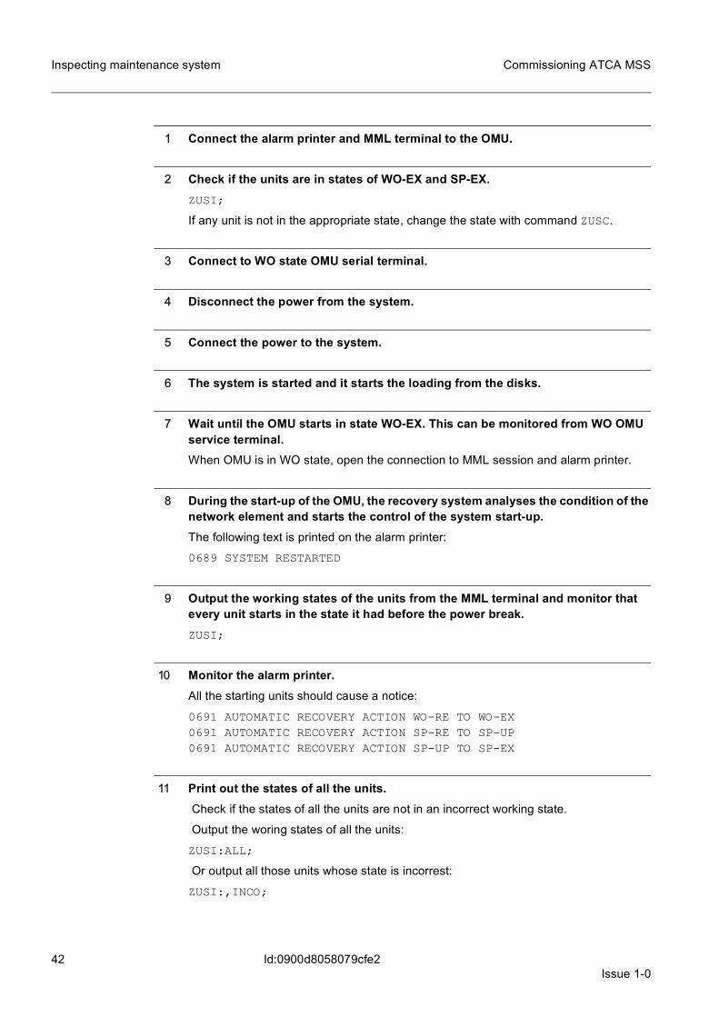
7.2 Testing the recovery from a complete power break in the systemThe purpose of the test is to test the recovery of the system from a complete power break. The system should automatically separate the units without power from use after the power break and start the units in their correct working state after the power is on again.
42Issue 1-0
Commissioning ATCA MSS
Id:0900d8058079cfe2
Inspecting maintenance system
1 Connect the alarm printer and MML terminal to the OMU.
2 Check if the units are in states of WO-EX and SP-EX.ZUSI;
If any unit is not in the appropriate state, change the state with command ZUSC.
3 Connect to WO state OMU serial terminal.
4 Disconnect the power from the system.
5 Connect the power to the system.
6 The system is started and it starts the loading from the disks.
7 Wait until the OMU starts in state WO-EX. This can be monitored from WO OMU service terminal.When OMU is in WO state, open the connection to MML session and alarm printer.
8 During the start-up of the OMU, the recovery system analyses the condition of the network element and starts the control of the system start-up. The following text is printed on the alarm printer:
0689 SYSTEM RESTARTED
9 Output the working states of the units from the MML terminal and monitor that every unit starts in the state it had before the power break.ZUSI;
10 Monitor the alarm printer.All the starting units should cause a notice:
0691 AUTOMATIC RECOVERY ACTION WO-RE TO WO-EX0691 AUTOMATIC RECOVERY ACTION SP-RE TO SP-UP0691 AUTOMATIC RECOVERY ACTION SP-UP TO SP-EX
11 Print out the states of all the units. Check if the states of all the units are not in an incorrect working state.
Output the woring states of all the units:
ZUSI:ALL;
Or output all those units whose state is incorrest:
ZUSI:,INCO;
Issue 1-043
Commissioning ATCA MSS Checking the hardware configuration
Id:0900d8058079cfe3
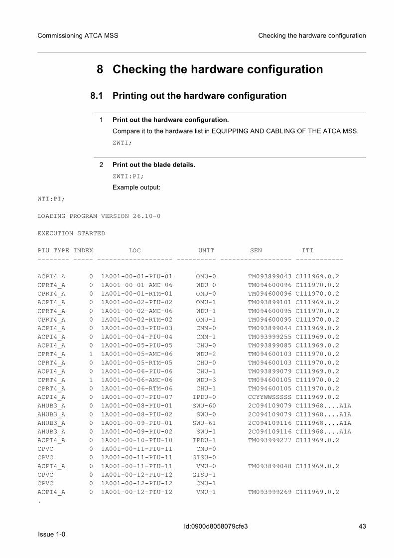
8 Checking the hardware configuration
8.1 Printing out the hardware configuration
1 Print out the hardware configuration.Compare it to the hardware list in EQUIPPING AND CABLING OF THE ATCA MSS.
ZWTI;
2 Print out the blade details.ZWTI:PI;
Example output:
WTI:PI;
LOADING PROGRAM VERSION 26.10-0
EXECUTION STARTED
PIU TYPE INDEX LOC UNIT SEN ITI-------- ----- ------------------- ---------- ------------------ ------------
ACPI4_A 0 1A001-00-01-PIU-01 OMU-0 TM093899043 C111969.0.2CPRT4_A 0 1A001-00-01-AMC-06 WDU-0 TM094600096 C111970.0.2CPRT4_A 0 1A001-00-01-RTM-01 OMU-0 TM094600096 C111970.0.2ACPI4_A 0 1A001-00-02-PIU-02 OMU-1 TM093899101 C111969.0.2CPRT4_A 0 1A001-00-02-AMC-06 WDU-1 TM094600095 C111970.0.2CPRT4_A 0 1A001-00-02-RTM-02 OMU-1 TM094600095 C111970.0.2ACPI4_A 0 1A001-00-03-PIU-03 CMM-0 TM093899044 C111969.0.2ACPI4_A 0 1A001-00-04-PIU-04 CMM-1 TM093999255 C111969.0.2ACPI4_A 0 1A001-00-05-PIU-05 CHU-0 TM093899085 C111969.0.2CPRT4_A 1 1A001-00-05-AMC-06 WDU-2 TM094600103 C111970.0.2CPRT4_A 0 1A001-00-05-RTM-05 CHU-0 TM094600103 C111970.0.2ACPI4_A 0 1A001-00-06-PIU-06 CHU-1 TM093899079 C111969.0.2CPRT4_A 1 1A001-00-06-AMC-06 WDU-3 TM094600105 C111970.0.2CPRT4_A 0 1A001-00-06-RTM-06 CHU-1 TM094600105 C111970.0.2ACPI4_A 0 1A001-00-07-PIU-07 IPDU-0 CCYYWWSSSSS C111969.0.2AHUB3_A 0 1A001-00-08-PIU-01 SWU-60 2C094109079 C111968....A1AAHUB3_A 0 1A001-00-08-PIU-02 SWU-0 2C094109079 C111968....A1AAHUB3_A 0 1A001-00-09-PIU-01 SWU-61 2C094109116 C111968....A1AAHUB3_A 0 1A001-00-09-PIU-02 SWU-1 2C094109116 C111968....A1AACPI4_A 0 1A001-00-10-PIU-10 IPDU-1 TM093999277 C111969.0.2CPVC 0 1A001-00-11-PIU-11 CMU-0 CPVC 0 1A001-00-11-PIU-11 GISU-0 ACPI4_A 0 1A001-00-11-PIU-11 VMU-0 TM093899048 C111969.0.2 CPVC 0 1A001-00-12-PIU-12 GISU-1 CPVC 0 1A001-00-12-PIU-12 CMU-1 ACPI4_A 0 1A001-00-12-PIU-12 VMU-1 TM093999269 C111969.0.2 .

44Issue 1-0
Commissioning ATCA MSS
Id:0900d8058079cfe3
Checking the hardware configuration
.
.ADPEM_A 0 1A001-00-PEM-01 PEM-0 XY071002411 C110576....A1AADPEM_A 0 1A001-00-PEM-02 PEM-1 XY071002405 C110576....A1AASMGR_A 0 1A001-00-SHM-01 SHMU-0 XY071301417 C110581....A1AASMGR_A 0 1A001-00-SHM-02 SHMU-1 XY071202460 C110581....A1AAFAMO_A 0 1A001-00-FAN-01 FAN-0 XY071300773 C110638....A1AAFAMO_A 0 1A001-00-FAN-02 FAN-1 XY071300772 C110638....A1AAFAMO_A 0 1A001-00-FAN-03 FAN-2 XY071300771 C110638....A1A
TOTAL OF 93 PLUG-IN UNITS
COMMAND EXECUTED
Verify that the SEN and ITI details can be found in every configured plug-in unit TYPE. These details are from the actual hardware. If the details are missing from some plug-in unit TYPE, verify the actual hardware configuration.
8.2 Checking the LAN device configuration
1 Check the states of the LAN unit.The states of the LAN unit should be WO state or SP state.
ZUSI:SWU;
ZUSI:EMB;
ZUSI:CNW;
2 Check the internal LAN configuration.ZWYI:L;
There should be four LANs configured: two for CNWs and two for EMBs.
ZWYI:U;
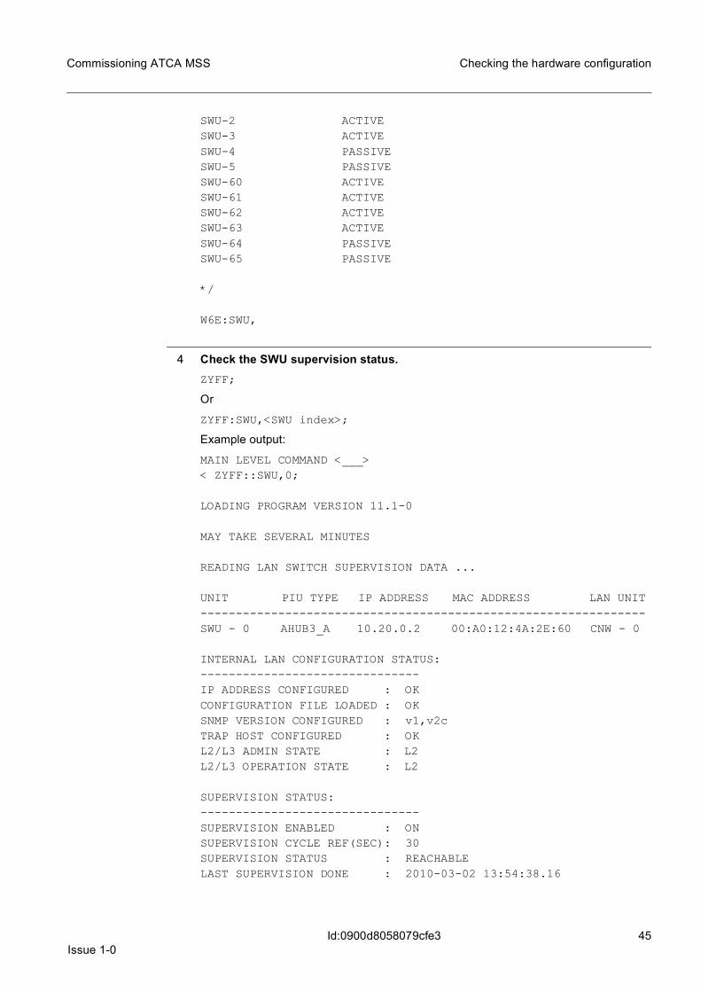
3 Check the switch activation status.IP addresses for managing the LANs are attached to OMU and all SWUs.
ZW6E:SWU;
Example output:
W6E:SWU,
/* IDENTIFY UNIT INDEX:
0 - 65279EXISTING IN THE ACTIVE TOPOLOGY
UNIT STATUS--------------------------SWU-0 ACTIVESWU-1 ACTIVE
Issue 1-045
Commissioning ATCA MSS Checking the hardware configuration
Id:0900d8058079cfe3
SWU-2 ACTIVESWU-3 ACTIVESWU-4 PASSIVESWU-5 PASSIVESWU-60 ACTIVESWU-61 ACTIVESWU-62 ACTIVESWU-63 ACTIVESWU-64 PASSIVESWU-65 PASSIVE
*/
W6E:SWU,
4 Check the SWU supervision status.ZYFF;
Or
ZYFF:SWU,<SWU index>;
Example output:
MAIN LEVEL COMMAND <___>< ZYFF::SWU,0;
LOADING PROGRAM VERSION 11.1-0
MAY TAKE SEVERAL MINUTES
READING LAN SWITCH SUPERVISION DATA ...
UNIT PIU TYPE IP ADDRESS MAC ADDRESS LAN UNIT---------------------------------------------------------------SWU - 0 AHUB3_A 10.20.0.2 00:A0:12:4A:2E:60 CNW - 0
INTERNAL LAN CONFIGURATION STATUS:-------------------------------IP ADDRESS CONFIGURED : OKCONFIGURATION FILE LOADED : OKSNMP VERSION CONFIGURED : v1,v2cTRAP HOST CONFIGURED : OKL2/L3 ADMIN STATE : L2L2/L3 OPERATION STATE : L2
SUPERVISION STATUS:-------------------------------SUPERVISION ENABLED : ONSUPERVISION CYCLE REF(SEC): 30SUPERVISION STATUS : REACHABLELAST SUPERVISION DONE : 2010-03-02 13:54:38.16

46Issue 1-0
Commissioning ATCA MSS
Id:0900d8058079cfe3
Checking the hardware configuration
PORT OPERATIVE ADMININDEX STATE STATE------------------------------0/1 : UP UP0/2 : UP UP0/3 : UP UP0/4 : UP UP0/5 : UP UP0/6 : UP UP0/7 : UP UP0/10 : DOWN UP0/11 : UP UP0/12 : UP UP0/13 : UP UP0/14 : UP UP0/15 : DOWN UP0/16 : DOWN UP1/1 : DOWN UP1/2 : DOWN UP1/3 : DOWN UP2/3 : DOWN UP
COMMAND EXECUTED
Check that the IP address is configured, trap host is configured and supervision status is reachable for every SWU.
8.3 Inspecting the LAN (Ethernet) switches
1 Connect to the LAN switch either through the serial port or a Telnet connection.
2 Check the software versions of the Ethernet switch.The version can be checked for example with the show version command where build version is the software version.
AHUB3# show versionbuild : RELEASE3.0.3_WR20ipmc : 00.06fpga ipmc : 02.51cpld : 5
AHUB3#
3 Check if the Ethernet switches have been assigned passwords.View mode is password protected. The password is admin by default. You can change this password by using the password command in global configuration mode.
See HUB BLADE USER GUIDE for information on Privileged mode passwords.

Issue 1-047
Commissioning ATCA MSS Checking the hardware configuration
Id:0900d8058079cfe3
4 Check the accesses to Base Ethernet and Fabric Ethernet switches.Session from serial or LAN connection can be started with fabric or base-ethernet com-mands.
AHUB3# ?base-ethernet : Start base ethernet CLIfabric-ethernet: Start fabric ethernet CLIcopy : Copy information to and from the bladeerase : Erase startup configurationblade-mgmt : Blade management configuration and statuslinux-shell : Start the Linux shellshow : Show configuration and statusexit : Logout from CLI sessionlogout : Logout from CLI sessionhelp : Operation instructions.AHUB3#AHUB3# fabric-ethernet
(SWU-0) # exitAHUB3# base-ethernet
(SWU-60) # exitAHUB3#
5 Check if the Ethernet switch identification (label information) is correct.The label information is stored in the Ethernet switch memory and can be changed to make identifying Ethernet switches easier.
Beginning of the command line prompt tells the current name. You can change this using the hostname command.
AHUB3-Fabric#AHUB3-Fabric# hostname SWU-0(SWU-0) #
6 Check if each Ethernet switch has been assigned a correct IP-address or that DHCP is enabled.(SWU-0) # show running-config
48Issue 1-0
Commissioning ATCA MSS
Id:0900d8058079cfe4
Checking unit diagnostics and working states
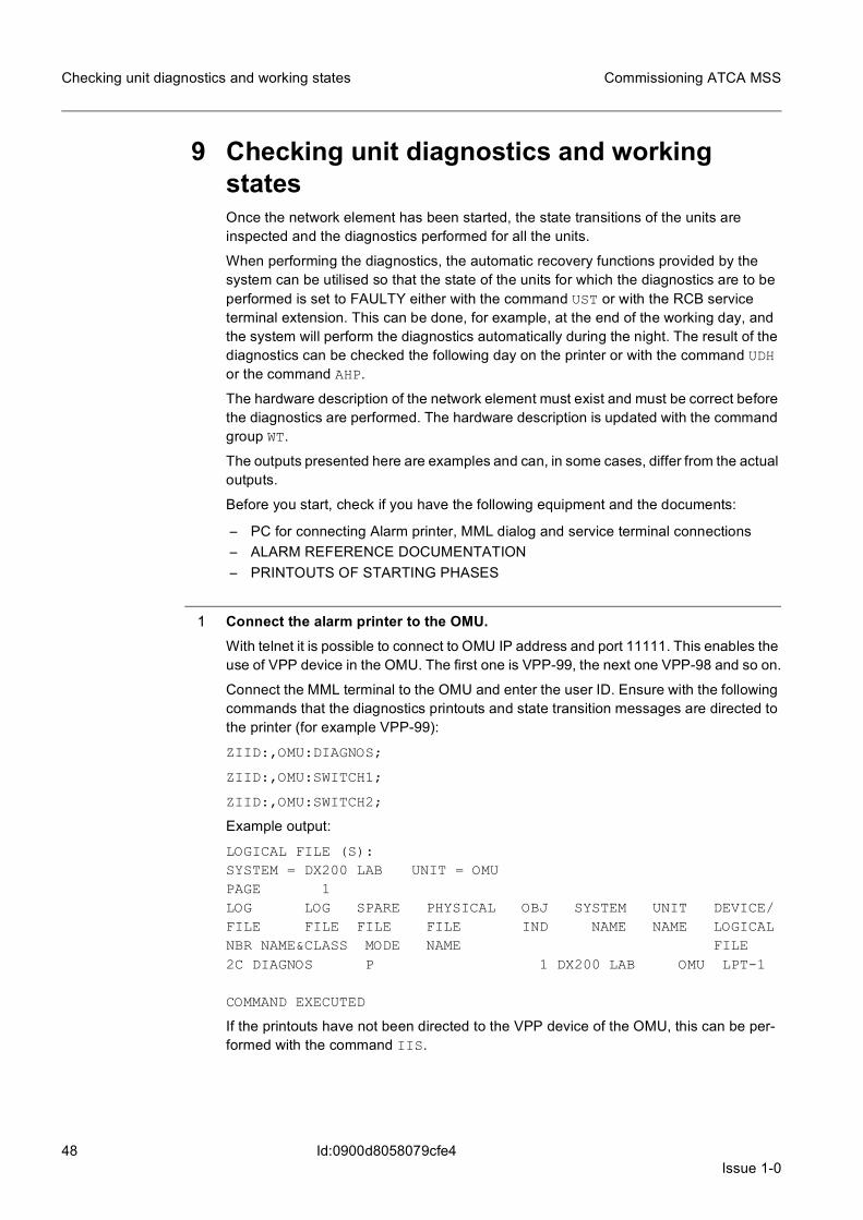
9 Checking unit diagnostics and working statesOnce the network element has been started, the state transitions of the units are inspected and the diagnostics performed for all the units.
When performing the diagnostics, the automatic recovery functions provided by the system can be utilised so that the state of the units for which the diagnostics are to be performed is set to FAULTY either with the command UST or with the RCB service terminal extension. This can be done, for example, at the end of the working day, and the system will perform the diagnostics automatically during the night. The result of the diagnostics can be checked the following day on the printer or with the command UDH or the command AHP.
The hardware description of the network element must exist and must be correct before the diagnostics are performed. The hardware description is updated with the command group WT.
The outputs presented here are examples and can, in some cases, differ from the actual outputs.
Before you start, check if you have the following equipment and the documents:
– PC for connecting Alarm printer, MML dialog and service terminal connections– ALARM REFERENCE DOCUMENTATION– PRINTOUTS OF STARTING PHASES
1 Connect the alarm printer to the OMU.With telnet it is possible to connect to OMU IP address and port 11111. This enables the use of VPP device in the OMU. The first one is VPP-99, the next one VPP-98 and so on.
Connect the MML terminal to the OMU and enter the user ID. Ensure with the following commands that the diagnostics printouts and state transition messages are directed to the printer (for example VPP-99):
ZIID:,OMU:DIAGNOS;
ZIID:,OMU:SWITCH1;
ZIID:,OMU:SWITCH2;
Example output:
LOGICAL FILE (S):SYSTEM = DX200 LAB UNIT = OMUPAGE 1LOG LOG SPARE PHYSICAL OBJ SYSTEM UNIT DEVICE/FILE FILE FILE FILE IND NAME NAME LOGICALNBR NAME&CLASS MODE NAME FILE2C DIAGNOS P 1 DX200 LAB OMU LPT-1
COMMAND EXECUTED
If the printouts have not been directed to the VPP device of the OMU, this can be per-formed with the command IIS.
Issue 1-049
Commissioning ATCA MSS Checking unit diagnostics and working states
Id:0900d8058079cfe4
2 Print the working states of the units.Check if all the units of the network element are on the list (compare with the source data).
ZUSI;
Expected outcome:
– appropriate notifications on state changes– the diagnostics report that the unit is in working order:
0724 TOTAL DIAGNOSIS EXECUTED - UNIT OK
The following text is displayed after the execution of every partial diagnosis:
0715 PARTIAL DIAGNOSIS EXECUTED
If the diagnostics report of a result is other than UNIT OK, then follow the instructions given in the ALARM REFERENCE DOCUMENTATION.
9.1 Changing the states and the diagnosing of the unitsRepeat step 2 to step 5 to following units and to both indexes of each unit (for example OMU-0 and OMU-1):
– OMU ... OPERATION AND MAINTENANCE UNIT– STU ... STATISTICAL UNIT– CHU ... CHARGING UNIT– CMU ... CELLULAR MANAGEMENT UNIT– VLRU .. VISITOR LOCATION REGISTER UNIT– CMM ... CENTRAL MEMORY AND MARKER– GISU .. GENERIC IP SIGNALLING UNIT– VMU ... VIRTUALIZATION MANAGEMENT UNIT– IPDU .. IP DIRECTOR UNIT– SWU ... SWITCHING UNIT– EMB ... ETHERNET BASED MESSAGE BUS– CNW ... COMMUNICATION NETWORK– SHMU .. SHELF MANAGEMENT UNIT
1 Connect the alarm printer and MML terminal to the OMU.
2 Check the state of the units.ZUSI:<unit type>,<unit index>;
Example command:
ZUSI:<CMM>,<1>;
3 If the state of the units is WO-EX, change it first to SP-EX and then to TE-EX. If the state is SP-EX, change it directly to TE-EX.ZUSC:<unit type>,<unit index>:SP;
ZUSC:<unit type>,<unit index>:TE;

50Issue 1-0
Commissioning ATCA MSS
Id:0900d8058079cfe4
Checking unit diagnostics and working states
Example command:
ZUSC:CMM,1:SP;
ZUSC:CMM,1:TE;
☞ CNW diagnostics can be run in WO-EX state:
ZUDU:CNW,0;
Skip therefore step 3 and step 5 when running the CNW diagnostics.
4 Run the diagnostics on the units.ZUDU:<unit type>,<unit index>;
Example command:
ZUDU:MCHU,1;
5 Change the unit state back to the original SP or WO.ZUSC:<unit type>,<unit index>:SP;
ZUSC:<unit type>,<unit index>:WO;
Example command:
ZUSC:CMM,1:SP;
ZUSC:CMM,1:WO;
9.2 Testing the spare units
1 Equip the network element with the spare blades (if available).Repeat the diagnostics as described in this section.
2 Write a failure report about the blades that are found faulty.

Issue 1-051
Commissioning ATCA MSS Copying additional software
Id:0900d8058079cfe5
10 Copying additional software
1 Copy the change deliveries.Check the Change Deliveries (CD) level of the software build and install the CDs that have not been installed. See further instructions in the Change Delivery document.
ZWNH;
2 Restart the system.ZUSS:SYM:C=DSK;
After the restart, check that all the units have reached the correct working states and check with the command DCD that the correct time zone has been set.
52Issue 1-0
Commissioning ATCA MSS
Id:0900d8058079b611
Initial hardware setup
11 Initial hardware setupBefore configuring SW build into use, initial HW setup for ADX2 usage needs to be done. If this is not done, it will cause many problems later.
• ACPI4-A– BIOS settings need to be checked. In the beginning, just check OMU unit set-
tings.– ☞ It is important that in the first time when taking new environment in use,
there are only OMU units attached to the shelf. Other units must be unplugged.This is because EMB address initialization, in new environment default values in EMB address will cause problems at least in multi-shelf environ-ments
• AHUB3-A– Initial settings need to be checked.
To make the environment work, the most important ones are the BI settings. Disable port 2/1, which is between the BI switches. If not disabled, this will cause message duplication in the EMB and may also cause HW database corruption.
– If there are problems in accessing the FI switch, check HBRT3-A status from the shelf manager (clia board 8 or clia board 9). If HBRT3-A is disabled, activate the switch with command clia activate.
Issue 1-053
Commissioning ATCA MSS Build installation
Id:0900d8058079b680
12 Build installation
12.1 Initial software build in the USBThere are two ways to get the initial build to the disk. One is USB stick, the other is moving CPRT4-A to other environment where to copy the build.
To create DX bootable USB stick:
• Format the USB stick in classic DX (DCAR-A plug-in unit) or ATCA where a USB port is available. The MASHAN service terminal command is ZMID:U0-USB00,F16,T,BOOT;
☞ The USB stick cannot be formatted bootable with an MML command. Also, only the F16 file format is supported for a bootable stick.
• Copy the minidebugger to the USB stick.– Use MINIDEBW.CMD (executed with MML command ZIDE) to create the
minidebugger to the OMU disk. This command creates an MDEBUG folder to the disk root.
– Use MINIDEBF.CMD to copy the minidebugger from disk to the USB.
☞ If you want to install the build from the USB stick, you also need to create this initial build in some working environment. This basically means running the NEWMML script and creating empty files.
It is not mandatory to copy files in element to the USB stick. Only mandatory task is formatting. You can also for example ZIP & copy with FTP the required files in the network element and then copy files to the USB in a local PC.
For minidebug, you need an MDEBUG folder and BOLEROGX.IMG in the USB root.
For SW build, you need this new sw build (with empty files created) in the USB stick in the same directory structure as there is on the disk.
12.2 Copying the build to the target element diskBoot the OMU CPU with the USB stick you created. If booting is not started from the USB, check the boot order from the BIOS.
When the unit is in the minidebug state, format the disk with command ZMID, if neces-sary.
Copy the build from the USB to the WDU for example with command
ZMMDR:U0-/X0_2_7_0/,W0-/X0_2_7_0
12.3 Copying the first build to the network elementWhen installing new ATCA HW for running ADX2 or application builds, take the following into account:
When equipping a new element for the first time, create only the base configuration with
• cabinet • shelves • air filters • EMB
54Issue 1-0
Commissioning ATCA MSS
Id:0900d8058079b680
Build installation
• PEM and FANs • SHMU • SWUs • OMUs • internal LAN configuration
These units have to be in the working state:
• OMU-0 • SHMUs • SWUs • CNWs • EMBs
When the configuration is ready, check the following details:
• LAN management to all SWUs is functioning.– This can be checked for example with command
ZYFF; • There are no FLTY flags in the units. • The SHMU units are up, and connection to system manager functions.
– The connection can be checked from the active shelf managers with clia session command.
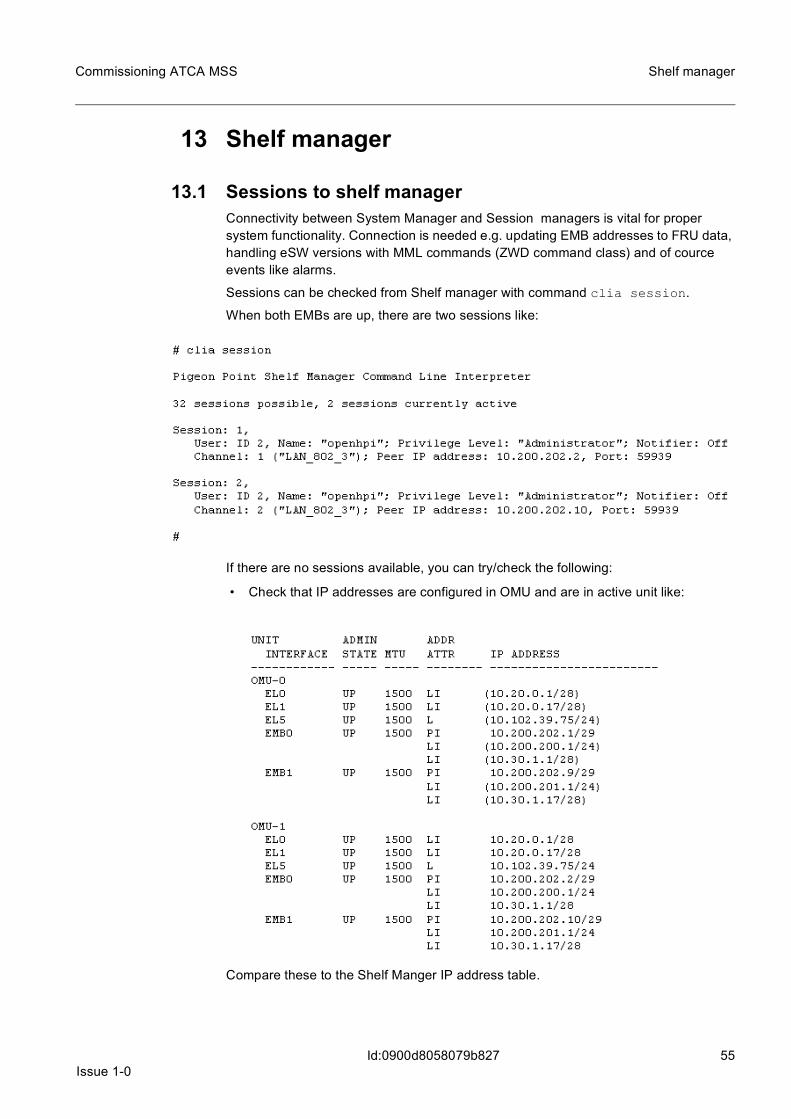
Issue 1-055
Commissioning ATCA MSS Shelf manager
Id:0900d8058079b827
13 Shelf manager
13.1 Sessions to shelf managerConnectivity between System Manager and Session managers is vital for proper system functionality. Connection is needed e.g. updating EMB addresses to FRU data, handling eSW versions with MML commands (ZWD command class) and of cource events like alarms.
Sessions can be checked from Shelf manager with command clia session.
When both EMBs are up, there are two sessions like:
If there are no sessions available, you can try/check the following:
• Check that IP addresses are configured in OMU and are in active unit like:
Compare these to the Shelf Manger IP address table.

56Issue 1-0
Commissioning ATCA MSS
Id:0900d8058079b827
Shelf manager
• Check the IP address in the Shelf Managers. This can be checked with command ifconfig. If IP address exists, try to ping to OMU addresses (both physical and logical addresses.
• If there are no IP addresses, try to configure them manually. Then try to ping the OMU IP address.For example, to configure SHMU-0 eth0:ifconfig eth0 10.200.200.10 netmask 255.255.255.0
– Then you can try to ping the OMU address, for example: ping 10.200.200.1 – The same can be tried with other EMB, for example:
ifconfig eth1 10.200.201.10 ping 10.200.201.1
• If ping does not work from the shelf manager to the system manager (OMU), but both ends ping their own addresses, check the AHUB configuration. Check that OMU ports are ok and also the port to the shelf managers is up (port 2/4).
• If ping works, but there are still no sessions, try to renew the IP addresses in the shelf manager.In the active shelf manager, give commandclia dhcp restart
• If ping works and ip addresses are correct in the shelf manager, but there are still no sessions, try OMU or system restart. In the next startup, the system should initialize the connection to the shelf managers.
• If only one session exists, check the EMB states. If the EMB is in the SE state, there is no active session in that EMB.
• There can be more than two sessions. These usually result from switchovers. Unused sessions are cleared automatically after a while.
13.2 Shelf manager IP addressesFairly often, when installing multi shelf environments, there are connectivity problems with the Shelf Managers. One source of problems are the Shelf Manager IP addresses.
The following figure describes the IP addresses of a one-cabinet configuration. The grey addresses are the logical addresses which are configured in the active unit.
The IP addresses can be checked with command ZQRI; or with ifconfig in the shelf managers.
The IP addresses can be configured also manually, for example:

Issue 1-057
Commissioning ATCA MSS Shelf manager
Id:0900d8058079b827
If config eth0 10.200.200.10 netmask 255.255.255.0
13.3 Telnet connection from OMU to shelf managerIt is possible to start a telnet session from the OMU to the Shelf managers. This may help to troubleshoot problems with the shelf manager in case when there is no serial port cable to the shelf managers for remote sessions.
Remote session can be taken through the VIMMLA service terminal extension, for example:
ZLP:1,VIM
Z1CT:0:10.200.200.3

58Issue 1-0
Commissioning ATCA MSS
Id:0900d8058079b827
Shelf manager
By default, telnet may have been disabled for security reasons, but for internal debug-ging it can be enabled.
Enabling telnet sessions to shelf manager can be done by adding sessions to shelf manager /etc/securetty file.
For telnet sessions, there must be ttyp devices like ttyp0 in the securetty file. If there are not, you can add these with VI editor:
1. vi /etc/securetty2. press a -key to change to edit mode3. use arrow keys to move to the end of last line in the file and press enter to create
new line. Add few devices to the file: • ttyp0 • ttyp1 • ttyp2 • ttyp3 • ttyp4
4. Exit the edit mode by pressing the Esc key.5. Type character string :wq, press enter to write, and exit from the editor.6. You can check the file for example
cat /etc/securetty
Now you can try to have a telnet session from the OMU to the shelfmanager.

Issue 1-059
Commissioning ATCA MSS AHUB3-A troubleshooting
Id:0900d8058079b9a9
14 AHUB3-A troubleshooting
14.1 Ports remain disabledThere may be problems with autonegotion in the Fabric interface. One way to get the ports up in the RTM is presented below. So remote end is with Autonegotion.
There may be similar problems with ACPI4-A. The link speed should be 10G, but for some reason, AHUB3-A negotiates 1G link speed.
In this case, do the same as below and also restart the corresponding ACPI4-A (with shelf manager clia deactivate/activate).
If this does not help, try to physically unplug the ACPI4-A and then install it back in the shelf.
14.2 AHUB3-A does not get the IP address or the IP address is wrongThis can happen for example if LAN manamenet IP addresses change in the SW build configuration.
If the addresses are wrong, just drop the interface down and back to up. It should renew the IP address.
Log in to AHUB3-A. You can use direct service terminal or ZW6T command (to CNW switches) or VIMMLA service terminal extension to the EMB SWUs.
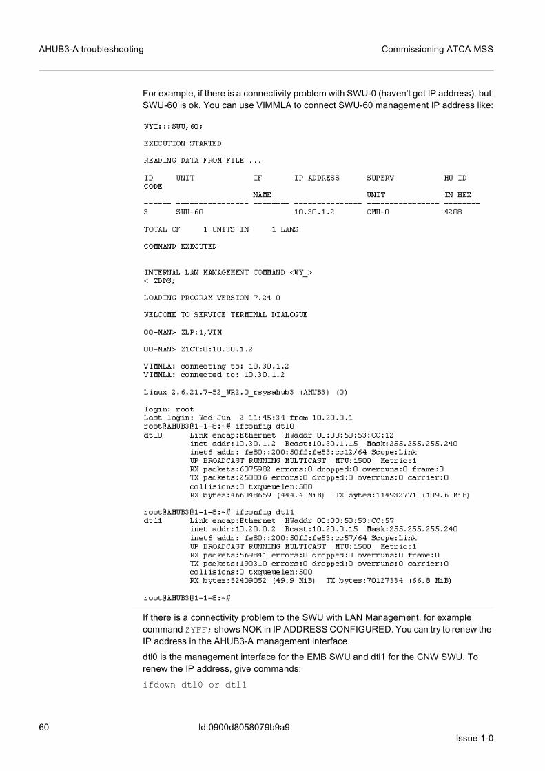
60Issue 1-0
Commissioning ATCA MSS
Id:0900d8058079b9a9
AHUB3-A troubleshooting
For example, if there is a connectivity problem with SWU-0 (haven't got IP address), but SWU-60 is ok. You can use VIMMLA to connect SWU-60 management IP address like:
If there is a connectivity problem to the SWU with LAN Management, for example command ZYFF; shows NOK in IP ADDRESS CONFIGURED. You can try to renew the IP address in the AHUB3-A management interface.
dtl0 is the management interface for the EMB SWU and dtl1 for the CNW SWU. To renew the IP address, give commands:
ifdown dtl0 or dtl1

Issue 1-061
Commissioning ATCA MSS AHUB3-A troubleshooting
Id:0900d8058079b9a9
ifup dtl0 or dtl1
Check also that the dhcpd service is up.
From the AHUB main menu to blade-mgmt.
show service
Restart dhcpd (In blade-mgmt).
config
service dhcpd restart
14.3 Firmware versionsSwitching SW versions in flash can be checked with flashver command in linux.
The SW can be changed for example in reboot command
14.4 Problems with SNMPAHUB3-A has an IP address, but SNMP queries do not function. For example with command ZYFF; you cannot see the port details.
1. Check that there is a correct LAN topology in use.ZW6G:T3;
2. Check that there are no files ending with ‘restored’ in the system.root@AHUB3@1-1-8:/# find / -iname "*restored"
3. If there are, remove them.root@AHUB3@1-1-8:/# rm -i `find / -iname "*restored"`
4. Upload the configuration to the TFTP server and then download it back to the switch.AHUB3# copy system:running-config tftp://10.30.0.1/ASWDIR/TGYCA300.IMGAHUB3# copy tftp://10.30.0.1/ASWDIR/TGYCA300.IMG system:running-config

62Issue 1-0
Commissioning ATCA MSS
Id:0900d8058079b9a9
AHUB3-A troubleshooting
5. Check again that there are no files ending with ‘restored’ in the system.root@AHUB3@1-1-8:/# find / -iname "*restored"
6. Load the default configurations.ZYFM:UCF:SWU,60:;
7. Check again that there are no files ending with ‘restored’ in the system.root@AHUB3@1-1-8:/# find / -iname "*restored"
8. Check the SNMP configuration.root@AHUB3@1-1-8:/# cat /etc/snmp/snmpd.confThere should be the following lines in the end of the file:[Figure 8]
9. Restart the SNMP daemon.AHUB3# blade-mgmtAHUB3(blade-mgmt)# confAHUB3(cnfg)# service snmpd restart
10. Check that the configuration is ok.ZYFF;YFE:ALL;W6I…

Issue 1-063
Commissioning ATCA MSS DMX units
Id:0900d8058079b9c2
15 DMX unitsIn system level and from DMX point of view, functionality is quite the same in classic hw and in ATCA hw. We have quite the same tools in use for fault debugging.
• minidebugger state • blackbox • different logs
– computer logs for DMX and Linux units, log collection to OMU (ZDV mml command)
– OS logs– SEL logs in Shelf Manager– event log for Lan Management– Posix log– Ethernet Post Office log
• message monitoring same as in Classic • alarms • startup printouts • load monitoring

64Issue 1-0
Commissioning ATCA MSS
Id:0900d8058079cf01
VMU or other units
16 VMU or other units
16.1 BIOS settingsA fairly common cause for problems with VMU units are BIOS settings. Wrong BIOS settings usually prevent virtualized units to rise up.
• IntelVT-d must be enabled (Default value is Disabled)Symptom if disabled: Child units do not get IP address in loading (Connection timed out), Remote connections to VMU units not working, problems with EMB.
• Processor Virtualization need to be enabled.Symptom if disabled: Virtualized units do not load up.
• SR-IOV must be enabled (Default value Enabled).Symptom if disabled: Currently EL0 & EL1 and EL4 & EL5 interfaces are using SR-IOV. If it is disabled, these interfaces are not working.
• Hyperthreading must be enabled (Default value Disabled).Problems occur when there are two VLRUs and one GISU in the same VMU. In this case core reservation is 1+1+3 = 5 = more than we have without HT.This can be checked from VMU with command:0082-$ cat /proc/cpuinfo |grep proc processor 0processor 1processor 2processor 3processor 4processor 5processor 6processor 7
16.2 Incorrect amount of memory in VMUIn some fault situations in blade startup not all the memory is visible to BIOS.
Reason for this could be that memory modules are not properly installed or there is some temporary problem in BIOS.
In these situations, you may notice that some virtual units are not started at all in the VMU where a memory problem appears. In the lnx-log, you can see the following kinds of printouts:

Issue 1-065
Commissioning ATCA MSS VMU or other units
Id:0900d8058079cf01
Recovery for this failure is to reboot the whole cpu-blade where the VMU is located and verify for example with top print that a correct amount of memory is allocated to the VMU.
16.3 VMAKVM fileWhen virtual units are created in the equipment database, the system checks the exis-tence of the unit from VMAKVMGX.TXT file. If the unit is found and the relation is correct, the unit can be created and information of the EMB address is written in the VMAEMBGX.TXT file in the ASWDIR directory.
CPU affinity setting can handle the usage of IO thread, CPU emulation threads, interrupt handler, and other similar.
When HT is used, cores 0-3 are the physical cores and 4-7 are logical cores in a way that 0 and 4 are actually the same physical core (1 and 5, 2 and 6, and 3 and 7, corre-spondingly).
• This option specifies the CPU affinity for the I/O and vCPU threads of the virtual machine. vCPUs are separated by a semi-colon (‘;’) and CPU cores by a comma (‘,’). Any vCPUs without specified affinity can run on any CPU core.
• Example: This virtual machine has been configured with cpus=2 option, so we need to specify CPU affinity for the I/O thread and two vCPUs. The whole configuration option must be given on a single line. The I/O thread will be bound to physical CPUs 0 and 1, allowing the host Linux kernel to schedule it to these CPUs as it wishes, and the vCPUs 0 and 1 are bound to physical CPUs 2 and 3.
• affinity=io:0,1;0:2;1:3
16.4 Handling virtual unitsShow VMs in VMU:
Restart VM in VMU:
0082-$ lnx-vmanakvm -r STU-0Restarted STU-00082-$

66Issue 1-0
Commissioning ATCA MSS
Id:0900d8058079cf01
VMU or other units
Open remote connection to VM:
Using lnx-vmanakvm-client command is the only way to get the virtual machines startup printout. For example restart VM and immediately open the client connection:
16.5 List of Programs: lnx-launcherList of all prbs started by launcher.Most programs have DMXPID that corresponds to program tasks in the DMX unit.

Issue 1-067
Commissioning ATCA MSS VMU or other units
Id:0900d8058079cf01
For example. lnx-log-sender-d process with DMXPID 3BD corresponds to LSEND DMX process.
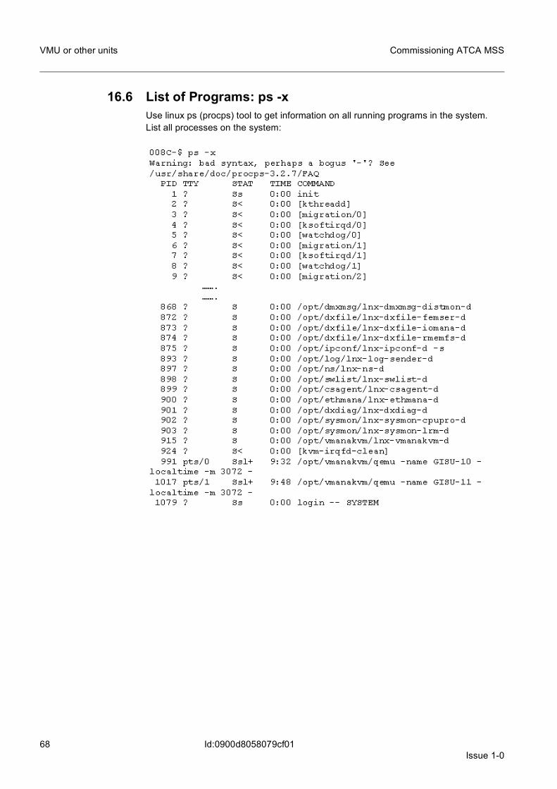
68Issue 1-0
Commissioning ATCA MSS
Id:0900d8058079cf01
VMU or other units
16.6 List of Programs: ps -xUse linux ps (procps) tool to get information on all running programs in the system.List all processes on the system:

Issue 1-069
Commissioning ATCA MSS VMU or other units
Id:0900d8058079cf01
16.7 List of LinDX software modulesList of LinDX software modules loaded in VMU:
16.8 DX Error codes in Linux unitPrinting DX error codes in VMU:
16.9 Copying files from Linux unit to OMU diskCopying files to DX unit (OMU WDU-0):
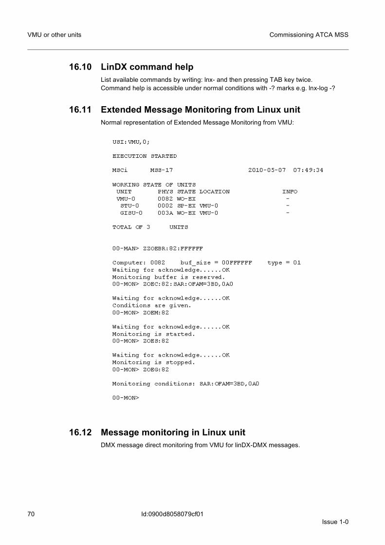
70Issue 1-0
Commissioning ATCA MSS
Id:0900d8058079cf01
VMU or other units
16.10 LinDX command helpList available commands by writing: lnx- and then pressing TAB key twice.Command help is accessible under normal conditions with -? marks e.g. lnx-log -?
16.11 Extended Message Monitoring from Linux unitNormal representation of Extended Message Monitoring from VMU:
16.12 Message monitoring in Linux unitDMX message direct monitoring from VMU for linDX-DMX messages.
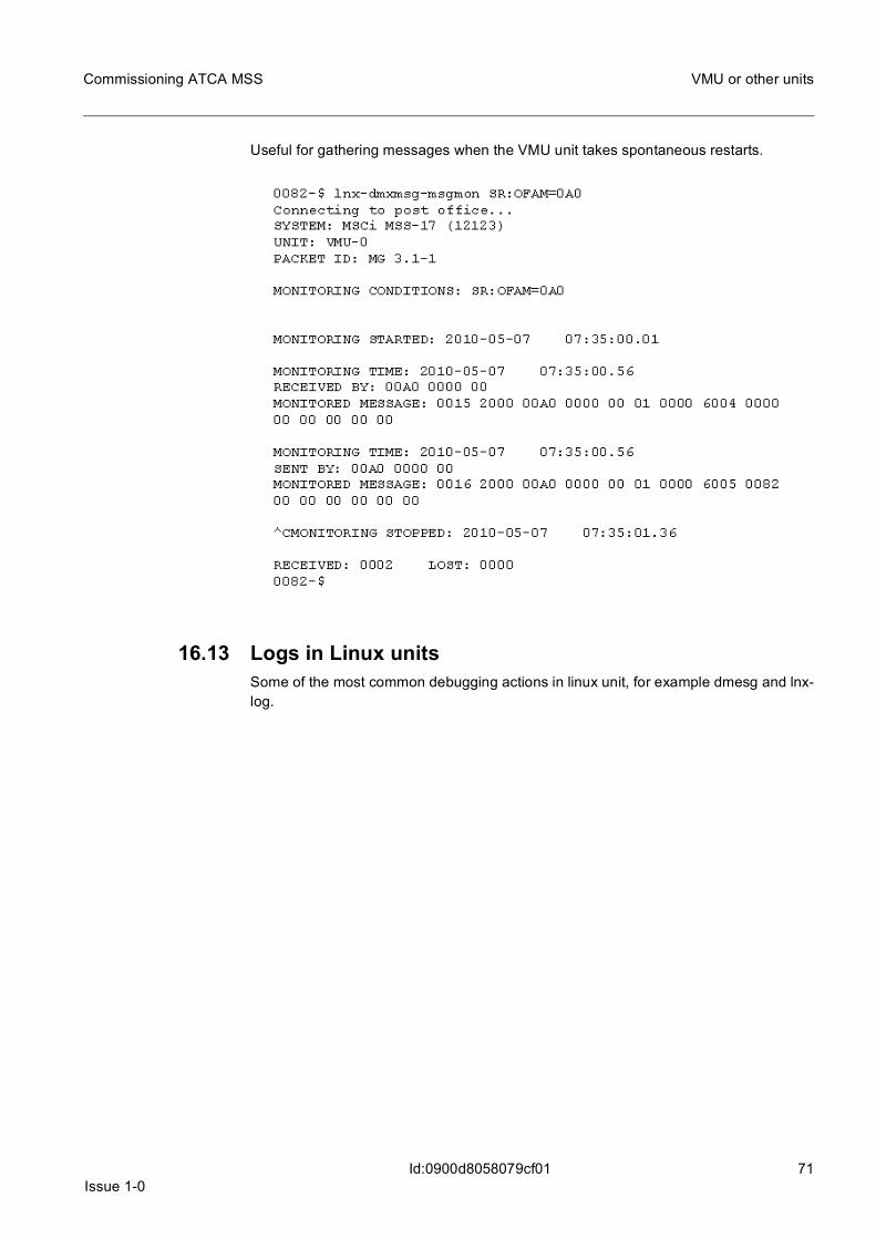
Issue 1-071
Commissioning ATCA MSS VMU or other units
Id:0900d8058079cf01
Useful for gathering messages when the VMU unit takes spontaneous restarts.
16.13 Logs in Linux unitsSome of the most common debugging actions in linux unit, for example dmesg and lnx-log.

72Issue 1-0
Commissioning ATCA MSS
Id:0900d8058079cf01
VMU or other units
Use dmesg commans to print events in startup to present moment. This can be useful if linux is in a restart loop.
lnx-log without parameters shows only error logs. To see test logs, specify log type: lnx-log -T
16.14 Memory Usage in Linux unitsMemory usage in linux.

Issue 1-073
Commissioning ATCA MSS VMU or other units
Id:0900d8058079cf01
Use following commands to get more details of memory usage.

74Issue 1-0
Commissioning ATCA MSS
Id:0900d8058079cf01
VMU or other units
16.15 System Information in Linux unitDisplay unit and system information:

Issue 1-075
Commissioning ATCA MSS VMU or other units
Id:0900d8058079cf01
16.16 Active variables from Linux UnitDisplay active variables in the system:
16.17 Services in Linux unitPrint out used services in VMU.For example print all services that start with an "a":

76Issue 1-0
Commissioning ATCA MSS
Id:0900d8058079cf01
VMU or other units
16.18 IP Configuration in Linux UnitCheck of ip-configuration in the system is made with unit logical addresses:
16.19 System LoadTOP is a good way to see the amount of free processing capacity left in VMU.
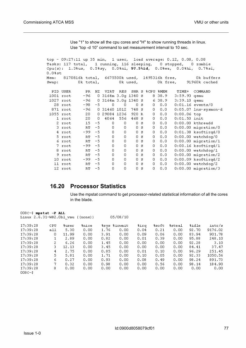
Issue 1-077
Commissioning ATCA MSS VMU or other units
Id:0900d8058079cf01
Use "1" to show all the cpu cores and "H" to show running threads in linux.Use “top -d 10” command to set measurement interval to 10 sec.
16.20 Processor StatisticsUse the mpstat command to get processor-related statistical information of all the cores in the blade.

78Issue 1-0
Commissioning ATCA MSS
Id:0900d8058079cf01
VMU or other units
Use the following command to get a continuous printout with an interval of 2 seconds from all cores:

Issue 1-079
Commissioning ATCA MSS ESW
Id:0900d805807c4bd0
17 ESW
17.1 Kontron CD update problems (ACPI4-A)When the creation of a bootable USB stick from Kontron Update CD fails, it can occur on account of these common problems:
– USB stick is not supported– USB stick contains existing data– USB stick in wrong filesystem
Resolution to these issues is to use simple USB sticks with minimal extra features(crypt-ing, CD emulation) and before creating the update stick, format it to FAT32 filesystem.

80Issue 1-0
Commissioning ATCA MSS
Id:0900d8058079d6de
Commands for collecting fault information
18 Commands for collecting fault informationIf you encounter problems in the installation or when taking a new network element in use, the following commands provide information which is useful to collect.
MML commandsZWQO:CR;
ZUSI;
ZWTI:P;
ZQRI;
ZWYI:U;
ZWYI:L;
ZWBI;
ZDDE:OMU,0:”ZLP:M,MAS”,”ZMXP:W0-BLCODE/*.*”, “ZMXP:W0-LFILES/*.*;
Shelf manager commands (active and spare ShMgr)version
lfconfig
getenv
cat /etc/shelfman.conf
cat /etc/shelfman.conf.nsn
cat etc/shelfman.conf.nsn-hpdl
cat etc/inetd.conf
cat etc/securetty
Shelf manager commands (active ShMgr)clia fru
clia session
clia getlanconfig 1
clia getlanconfig 2
clia getpefconfig
clia getconfigparam
clia fruinfo -x 0x20 0xfe
clia fruinfo -x 0x10 0
clia fruinfo -x 0x12 0
AHUB3-A (active and spare AHUB)AHUB3# show version
AHUB3# show running-config
AHUB3# base-ethernet
AHUB3-Base# show port all
AHUB3-Base# exit

Issue 1-081
Commissioning ATCA MSS Commands for collecting fault information
Id:0900d8058079d6de
AHUB3# linux-shell
root@AHUB3@1-1-8:/# ifconfig
root@AHUB3@1-1-8:/~# cat /etc/snmpd.conf | grep NSN
root@AHUB3@1-1-8:/# exit