commercialization of robotic prototypes: improving the concept for manufacturability and sale
TRANSCRIPT

Commercialization of Robotic Prototypes:
Improving the Concept for
Manufacturability and SaleJon Appleby
Engineering Manager, Boston
Acorn Product Development

Commercialization of Robotic Prototypes:
“The big problem is production. They overestimate how easy it is to do. It’s really hard.”
- Dimitry Grishin, xconomy 9/24/14

Late 2010
3 Employees
3 Robots
Mid 2012
70 Employees
100+ Robots
Improving on the Concept: Our Case Study

Improving on the Concept: Who we are

• Goals and requirements
• Breadboard development, component
selection
• Packaging options
• Drive-Train analysis
• Thermal modeling
• Structure – materials, process capability,
tooling approach?
• Manufacturing plan
• Cost analysis
• Down-selection of concepts, layouts,
performance metrics.
Improving on the Concept: How to Get There

• CAD design
• Updated analysis, thermal,
structural, tolerance
• Mfg Qualification, sourcing
plan.
• DFM integration from supply
base.
• Prototype build
• “Test” – Validate, don’t test.
• Production design, analysis
updates.
• Vendor management
• Tool reviews, mold-flow, First-
Article inspection
• Qualification
• CM build support
• Goals and requirements
• Breadboard development, component
selection
• Packaging options
• Drive-Train analysis
• Thermal modeling
• Structure – materials, process capability,
tooling approach?
• Manufacturing plan
• Cost analysis
• Down-selection of concepts, layouts,
performance metrics.
Improving on the Concept: How to Get There

The Prototype
Phase 1: Concept Generation, Evaluation
• Defining Realistic Goals/Objectives for the Commercial Product
• Designing for Manufacturing & Challenges
• Weight
• Strength
• Performance
Phase 2: Detailed Design
• CAD Implementations
• Analysis refinements
Phase 3: Test, Production Design
• Supply Chain Challenges
• Testing, Reliability
The Results
Improving on the Concept: A Case Study

The starting point:Machined aluminum
chassis. CNC,
expensive, heavy.
Compression, flat gasket
sealing
Bolt-in-place, all at once
assembly process.
Functional! Runs great, performs all basic tasks.
Too expensive, too heavy
Not a product, yet.
COTS / Commercial drive
components.
Poor reliability, hand-wired
Over-stressed components
The Prototype

• Weight targets –
• Prototype was 35+ lbs.
• Target = <25lbs. This includes “fixed” weight metrics like battery, motor, electronics.
• Rugged
• Needs to be run by un-trained operators on unknown terrain.
• Durable, pull it out, use, put it back.
• 60” repeated drop test requirement, thrown deployment
• Custom treads
• Modular payloads
• Need space, lots of it! Future expansion possibilities
• Common interface, power, high-speed signal, water-proof
• Costs
• Needed a reduction of ~>50% in BOM (Bill of Material) costs
• This is a must for the business case
Phase 1: Goals, Realistic and Otherwise

At the concept level:
How do we fit all the required components, and meet the
performance requirements?
Evaluated several different layouts, each with:
• Thermal solutions – solar load, internal power
dissipation
• Payload capability – how big, how many?
• Climbing performance - FWD, RWD, CG, traction,
balance
• Cost
Phase 1: Concept Generation

How to we design around the CNC chassis, what are the alternatives?
Plastics: Low cost
High complexity, feature rich
Good impact, low strength
Major risks to structural & tolerance goals
New supply chain
Thixomolding: Licensed magnesium die-cast process
~Low cost, high complexity
High strength, light weight.
More accurate than aluminum die casting
New supply chain
These choices impact our concept – we need analysis at the system level.
Gaining in popularity, camera shells,
transmission cases, consumer products.
Phase 1: Concept Generation - Materials
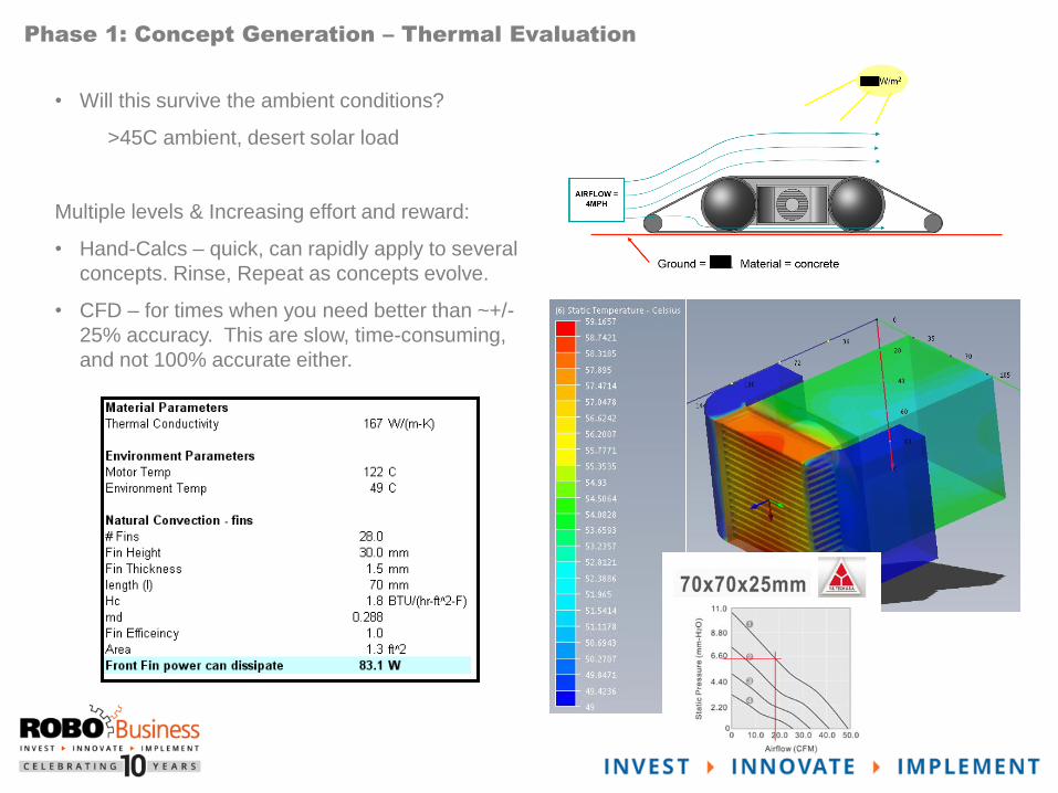
• Will this survive the ambient conditions?
>45C ambient, desert solar load
Multiple levels & Increasing effort and reward:
• Hand-Calcs – quick, can rapidly apply to several
concepts. Rinse, Repeat as concepts evolve.
• CFD – for times when you need better than ~+/-
25% accuracy. This are slow, time-consuming,
and not 100% accurate either.
Phase 1: Concept Generation – Thermal Evaluation

We were very concerned on the drop impact:
• High cantilevered loads
• Can we use SST for the shafts, aluminum, Ti?
• Relationship between shaft OD and attachment
method?
• Will our plastic construction concepts be strong
enough?
g
Phase 1: Concept Generation – Structural Evaluation
Took several concept iterations to support the cold
temperature drop performance.

Goals
+
Brainstorming
+
Layout Options
+
Material Choices
Analysis:
Thermal
Structural
Tolerance
Performance
Down-select,
Refine, Repeat
Phase 1: Concept Generation – Synthesis and Analysis

Centerpiece of the re-design effort was a common, single-molded chassis solution.
Early concept Model
Used for basic strength
calculations, molding
feedback, vendor RFQ
process
Production Design Model
Final FEA simulations
Tolerance analysis
Phase 2: Detailed Design - Chassis

Tolerances are a key aspect of the detailed design.
There are several approaches here, each with their own advantages:
Worst-Case
Analysis:
“RSS”, Root Sum
Squared
Direct Linearization
Method
Monte-Carlo
Setup Time
(fast)
(slow)(high)
Accuracy
(low)
In everyone’s toolbox. Not realistic, doesn’t hold up for
multi-part solutions. Can’t plan for the worst!
Good approximation, weights all variables the same.
Difficult to get a predicative value.
Good balance of speed, accuracy. Combines actual
process capability into a predictive approach.
“Holy Grail”. Iterative, simulation to predict results. This
is only as good as your input data. Not recommended
unless you have measured manufacturing data on your
parts.
Phase 2: Detailed Design – Tolerance Analysis

Direct Linearization Method Approach:
Element 1:
Plastic
Feature
Element 2:
Shaft
Dimension
Element 3:
Bolt fit in
clearance
hole
Sum generates a
composite
Gaussian curve
Adding up
our
elements,
based on a
sketched
loop
New Predicted Gaussian
3 sigma = 99.9%,
or 1350 DPPM
4 sigma =
99.997%, or 32
DPPM
Phase 2: Detailed Design – Tolerance Analysis
Element n:
Hole clearance,
biased by gravity

Gear Mesh Tolerance
Loop generation, from one side of the
gap to the other.
Expected
Center
distance?
Solving for our predicted distances:
Z (Sigma) = 3.98 @ +/- 0.27mm
Or, 99.997% of the time, we expect
+/- 0.27mm of the CAD distance.
Phase 2: Detailed Design – Tolerance Analysis

Revisit our thermal solutions, at a systems level.
Early runs shown – safe plastic touch limits exceeded!
Verification of motor peak
temperatures
Phase 2: Detailed Design – Thermal Refinement

Plastics are not an overnight solution.
SLA, 3D print, machined equivalents are good mock-ups, but not functional equivalents.
We decided to build an iterative option, with a sheetmetal core chassis.
This gave us a working platform, with the similar weight profile, in a short amount of time:
Interim path:
Production path:
Phase 2: Detailed Design - Chassis

• 4-slide, large molded chassis in 8
weeks?
• Yes, it can be done!
• Global Sourcing, Vetting
suppliers remotely
• Tooling < $80k investment
• Vendor Management is key
• Tooling approvals, design
approvals, be involved.
• In process photos are a must
• Weekly communication at a
minimum
In process B-plate
In process slide
Phase 3: Supply Chain Challenges
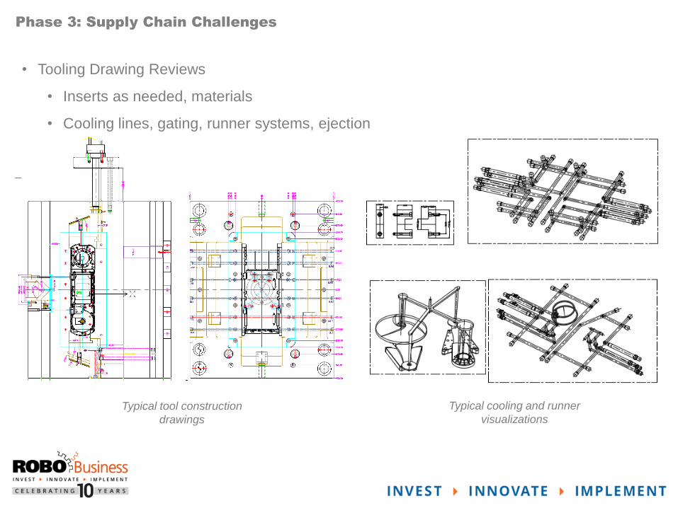
• Tooling Drawing Reviews
• Inserts as needed, materials
• Cooling lines, gating, runner systems, ejection
Typical tool construction
drawings
Typical cooling and runner
visualizations
Phase 3: Supply Chain Challenges

• Mold-Flow Studies
• Gate & Process
verification
• Venting, Air Trap
concerns
• Done ourselves, and/or
cross-checked from
vendor provided data.
Phase 3: Supply Chain Challenges

First Article Inspection
• Just because it’s done – doesn’t mean it’s right!
Phase 3: Supply Chain Challenges

• Drop Test – this was a challenge with a high mass
object…
• Aggressive 5ft drop requirement onto pavement
Phase 3: Testing, Reliability

• Still break a few eggs!
Traced back to material issue
at supplier.
Wrong level of impact modifier
not present in the parts
provided.
Phase 3: Testing, Reliability

Empirical measurements of thermal solutions.
Done @ max power conditions, per CFD models.
CFD modeling assumed max power
@ ½ speed. Testing did not include
airflow over robot. Predicted values
are 20% lower.
Good correlation otherwise (10-20%
resolution)
Phase 3: Testing, Reliability

Lighter, Cheaper, More Capable!
• Weight savings of >10lbs
• Reduction in cost by > than an order of magnitude!
• BOM Cost Start: $10,000’s per system
• BOM Cost End: $100’s per system
• Final part count:
• 3x Die-cast/Thixo
• 25x Injection Molding
• 7x CNC
• 19x Sheetmetal
• 2x Extrusion
• Passed ruggedness/durability tests
• Payload support increase by >100%
The Results:

In Action….
The Results:

• This is hard! Production design requires different tool kits, different
approaches to meet the cost, manufacturability, performance targets.
• Production design doesn’t mean limited functionality!
• The concept – it all starts there.
• Analyze, proceed with confidence, & validate
The Results:

Q and A

Thank You
(Come see the robot in Booth 520!)
Address Contact1 Broadway, 14th Floor Barry Braunstein
Cambridge, MA 02142 P 617-475-1541