commercialization and field distribution of … · commercialization and field distribution of...
TRANSCRIPT
COMMERCIALIZATION AND FIELD DISTRIBUTION OF SMART PEDESTRIAN CALL SIGNALS
Final Report
KLK715
N09-09
National Institute for Advanced Transportation Technology
University of Idaho
Dr. Richard Wall and Dr. James Frenzel
December 2009 – Revised June 2010

DISCLAIMER
The contents of this report reflect the views of the authors,
who are responsible for the facts and the accuracy of the
information presented herein. This document is disseminated
under the sponsorship of the Department of Transportation,
University Transportation Centers Program, in the interest of
information exchange. The U.S. Government assumes no
liability for the contents or use thereof.

1. Report No. 2. Government Accession
No.
3. Recipient’s Catalog No.
4. Title and Subtitle
Commercialization and Field Distribution of Smart Pedestrian Call
Signals
5. Report Date December,
2009
6. Performing Organization
Code
KLK715
7. Author(s)
Wall, Dr., Richard; Frenzel, Dr. James
8. Performing Organization
Report No.
N09-09
9. Performing Organization Name and Address 10. Work Unit No. (TRAIS)
National Institute for Advanced Transportation Technology
University of Idaho
PO Box 440901; 115 Engineering Physics Building
Moscow, ID 83844-0901
11. Contract or Grant No.
DTRT07-G-0056
12. Sponsoring Agency Name and Address
US Department of Transportation
Research and Special Programs Administration
400 7th Street SW
Washington, DC 20509-0001
13. Type of Report and Period
Covered Final Report:
August 2008 – December
2009
14. Sponsoring Agency Code
USDOT/RSPA/DIR-1
15. Supplementary Notes:
16. Abstract: The research on this project resulted in a new design for an accessible pedestrian system (APS) that uses Ethernet
communications to implement a distributed control system. Present APS designs represent a safety risk factor by
APS systems having undetectable failure modes that may play incorrect audible messages.
The systems consists of a controller unit housed in the traffic controller cabinet and interfaces to existing NEMA
TS1 and TS2 traffic controller cabinets at the field terminals. It supports from one to 16 pedestrian stations. The
controller unit uses a Linux based single board computer with dual Ethernet ports. The pedestrian stations use a
resource rich NXP processor reducing the number of components and size of circuit board.
All configuration and diagnostics is accomplished using a PC with a standard web browser and an Ethernet
connection. This interface reduces the size and cost of the unit mounted in the controller cabinet. The web page
provides real-time status of all controller inputs and the state of all pedestrian stations and the audio message
currently being played.
SNMP and STMP custom objects are used in such a way that each communications transaction is verified. A
network protocol is implemented that follows the guidelines for NTCIP custom objects.
17. Security Classif. (of
this report)
Unclassified
18. Security Classif. (of
this page)
Unclassified
19. No. of Pages
40
20. Price
…
Form DOT F 1700.7 (8-72) Reproduction of completed page authorized
Commercialization and Field Distribution of Smart Pedestrian Call Signals i
TABLE OF CONTENTS
FIGURES .................................................................................................................................. ii
TABLES ................................................................................................................................... ii
EXECUTIVE SUMMARY ...................................................................................................... 1
DESCRIPTION OF PROBLEM............................................................................................... 5
APPROACH AND METHODOLOGY ................................................................................... 9
AAPS Operations ................................................................................................................ 10
AAPS Supervisory Operations ........................................................................................... 10
AAPS Supervisory Operations - Status and Real-Time Monitoring .................................. 11
AAPS Operations – Pedestrian Station Operational Status ................................................ 13
AAPS Operations – System Configuration......................................................................... 13
AAPS Operations – Station Configuration ......................................................................... 18
AAPS Operations – Station Operating Parameters ............................................................. 19
AAPS Operations – Audio File Management ..................................................................... 20
AAPS Operations – Fault Detection and Recovery ............................................................ 22
NETWORK COMMUNICATIONS ...................................................................................... 24
System Operations – Communications ............................................................................... 24
Ethernet Implementation to support NTCIP ....................................................................... 24
SNMPv1 .......................................................................................................................... 25
SNMP OID’s ................................................................................................................... 26
SNMP Trap ..................................................................................................................... 28
APB Configuration Objects ............................................................................................ 29
AAPS HARDWARE .............................................................................................................. 30
Advance Pedestrian Controller ........................................................................................... 31
Advanced Pedestrian Button ............................................................................................... 32
Advanced Pedestrian Button – Future Research ................................................................. 34
FINDINGS; CONCLUSIONS; RECOMMENDATIONS ..................................................... 38
REFERENCES ....................................................................................................................... 39

Commercialization and Field Distribution of Smart Pedestrian Call Signals ii
FIGURES
Figure 1: AAPS system block diagram. .................................................................................... 9
Figure 2: AAPS system status web page. ............................................................................... 12
Figure 3: System configuration page. ..................................................................................... 14
Figure 4: System network properties page.............................................................................. 17
Figure 5: System time setup page. .......................................................................................... 18
Figure 6: Station control page. ................................................................................................ 20
Figure 7: Sound file entry page. .............................................................................................. 21
Figure 8: Partial NTCIP standards framework. ...................................................................... 25
Figure 9: MIB tree for major NTCIP nodes............................................................................ 27
Figure 10: Block diagram of an advanced pedestrian controller. ........................................... 32
Figure 11: Block diagram of an advanced pedestrian button. ................................................ 33
TABLES
Table 1: Definitions of Acronyms ............................................................................................ 4
Table 2: AAPS Operation Modes ........................................................................................... 15
Table 3: System Operating Parameters ................................................................................... 16
Table 4: AAPS Malfunction Compatibility Table .................................................................. 23
Table 5: Status OID Definitions ............................................................................................. 28
Table 6: Station Trap OID's Definitions for AAPS ................................................................ 29
Table 7: Configuration OID Definitions for AAPS ................................................................ 30

Commercialization and Field Distribution of Smart Pedestrian Call Signals 1
EXECUTIVE SUMMARY
Smart Signals is a term we have coined that refers to an enabling technology that allows for more
effective intersection control and adaption to real-time traffic operation requirements to enhance
highway performance and/or improve safety. Research in this area supports the NIATT objective
1 under the strategic initiative 1.4 that specifically identifies taking a revolutionary approach to
interfacing traffic controllers to field devices.
Innovative research on ―Smart Signals‖ concepts started in the fall of 2005 when it was noted
that current traffic signal devices display only a limited set of symbols, i.e. walk and don’t walk
icons for pedestrians and the common green, red, and yellow balls and arrows for vehicles.
Signals and sensors that utilize the Smart Signals technology can be used to display a wide range
of symbols and information that can change dynamically to reflect current road operations. The
difficulty of changing signal displays for temporary traffic patterns often confuses drivers and
generates unsafe intersection operations.
The integrity of traffic control systems today depend upon the malfunction management units
(MMU) or conflict monitors (CM) to be able to observe the state of all traffic and pedestrian
signals. This is accomplished by monitoring the voltage on the wires that connect the signal
lights to the load switches controlled by the traffic controller. Spatially distributing intelligent
control makes some of the automated controls unobservable by the MMU or CM. This is
certainly the case for signals that operate using Smart Signals technology. Early in 2008, the
Smart Signals research tested and implemented a secure distributed real-time control system for
safety critical systems by overlaying time precision protocol on the National Transportation
Communications for ITS Protocol (NTCIP).
However, representation for pedestrians who are blind or have low vision helped us realize that
the audible tones and messages that accessible pedestrian systems (APS) employ have the same
required degree of integrity as do the visual walk and wait signal for those with good visual
acuity. The microprocessors that are currently used in APS that controls what audible message
the pedestrians hear are based upon sensors in the pedestrian signal heads. This alone represents

Commercialization and Field Distribution of Smart Pedestrian Call Signals 2
a lapse in observability by the CM or MMU that can result in playing the incorrect audible
message thus putting a visually impaired pedestrian at risk.
Because of the risk to blind and visually impaired pedestrians that is not being addressed by
current industry designs, the research for the 2008 – 2009 project was initiated to develop an
advanced accessible pedestrian system (AAPS) based upon Smart Signals technology where the
audible messages can be verified and then provide an indication to the traffic system MMU or
CM. One of the specific objectives of this research effort was to identify an established
manufacturer of pedestrian signal systems and secure their commitment in helping us to get one
or more AAPS installed in a public intersection. The industry partner would help us to establish a
set of specifications that are progressive in promoting public safety and accessibility through
advanced features and enhanced reliability while keeping system costs for installation and
maintenance at or below the costs of existing APS installations.
Our success in meeting these goals can be measured by the number of publications, patent
applications, acquiring of additional external funding, students graduating with advanced degrees
and the devices developed for installation on public streets. We are currently working with
Campbell Company of Boise, ID, a well known manufacturer of pedestrian systems and APS
stations. This company has supplemented our research effort with funding and employed a
graduate student at their facility during the summer of 2009. Two patents have been applied for
in the area of AAPS and APS based on Smart Signals technologies. Two graduate students, who
worked on this project, received their Master of Science degrees in Computer Engineering in
May of 2009. Their work is currently being continued by two graduate and two undergraduate
Electrical Engineering students. Last year, we presented a paper at the 2009 Transportation
Research Board (TRB) meeting that was accepted for the TRB record. Presentations have been
made at regional workshops for industry practitioners and meetings for educators of the blind
and disabled.
Finally, our research has resulted in the development of a new generation of Smart Signals
pedestrian controls that meet the newest APS guidelines and have extensible capabilities for
features not considered at this time. The system began beta production in October 2009 and is
scheduled for beta site installation in February 2010. Based upon the reaction to previews of the

Commercialization and Field Distribution of Smart Pedestrian Call Signals 3
AAPS at industry trade shows and presentations at meetings for traffic professionals, the
suggestions for enhancements seem endless. Our research for the next year is in the area of
improved reliability to the extent that the Smart Signals research can begin to be applied to all
traffic signal devices. The industry acceptance of this revolutionary technology has been slow
and rightfully so because of the risk to life and property because of an undetected system failure.
The discussion of the development of the AAPS is presented in three areas: system operations
and functionality, the communication approach to support the distributed control approach, and
the electronic hardware needed to implement the control algorithms and communications. The
AAPS description is designed to inform the reader of not only the present AAPS capabilities, but
the kind of expansion capabilities possible in a software centric system. Although the detailed
descriptions of computer code and algorithms are beyond the scope of this report, this
information will be available in the form of theses for master’s degrees to be awarded in the
summer of 2010.
Our future research will continue to look at new ways the Smart Signals technology can improve
traffic safety, efficiency, and accessibility. But our main research will be to make certain that
what we are doing now represents the lowest risk, the highest availability of service, and the
greatest economic benefit. We will develop testing procedures and, if necessary, develop new
hardware for testing Smart Signals to assure those responsible for installing, maintaining, and
operating Smart Signals based traffic controls are of the highest reliability and dependability.

Commercialization and Field Distribution of Smart Pedestrian Call Signals 4
Table 1: Definitions of Acronyms
Acronym Definition
APS Accessible Pedestrian Signal
AAPS Advanced Accessible Pedestrian Signal
APB Advanced Pedestrian Button
APC Advanced Pedestrian Controller
AAPMS Advanced Pedestrian Management System
BPL Broadband Power Line
CGI Common Gateway Interface
CM Conflict Monitor
dbeacon Destination Beacon
DW Don’t walk
EoP Ethernet over Power line
EP-APS Extended press activated APS
FDW Flashing Don’t Walk
FTP File Transfer Protocol
HMI Human Machine Interface
HTML Hypertext Markup Language
IETF International Engineering Task Force
ibeacon Initiation Beacon
IP Internet Protocol
ITS Intelligent Transportation Systems
LAN Local Area Network
MIB Management Information Base
MMU Malfunction Management Unit
MUTCD Manual for Uniform Traffic Controller Devices
NTCIP National Transportation Communications for ITS Protocol
OID Object Identifier
PCM Pulse-Code Modulation
PDU Protocol Data Unit
SDLC Synchronous Data Link Control
SNMP Simple Network Management Protocol
TCP Transmission Control Protocol
UDP User Data Protocol
W Walk
WAN Wide Area Network

Commercialization and Field Distribution of Smart Pedestrian Call Signals 5
DESCRIPTION OF PROBLEM
Initially, the Smart Signals research focused on traffic signal devices that used network based
distributed control technology with plug and play capability. An advisory board was soon
established consisting of traffic signal designers from industry, state and federal traffic engineers,
academic researchers, and pedestrian advocacy groups including the Federation for the Blind.
Their input was solicited to help guide and direct our research effort as the Smart Signals
technology revolved and matured. As a result of the first advisory board meeting, the Smart
Signals research directed its attention to the deficiencies in the pedestrian signal and operations.
Three major areas for improvement were identified: The consistency and accuracy of countdown
pedestrian timers; pedestrian button failure modes that cannot be detected by the traffic
controller, MMU or CM; and the inability to adequately serve the visually impaired and mobility
handicapped pedestrian community.
In 2006, a team of electrical and computer engineering graduate and undergraduate students
successfully demonstrated that a countdown pedestrian timer based on Smart Signals
technologies can effectively maintain an accurate time for a wide range of traffic signal operating
conditions. These include emergency and transit vehicle preemption, as well as, different time-
of-day traffic signal timing plans.
In 2007, based on the advice of our advisory board, the Smart Signals researchers developed a
distributed control network based on the NTCIP. This research resulted in a new pedestrian
signal distributed around an intersection that is a logical extension for the computer program
running in the traffic controller on the street corner.
The traffic controller’s timing plans allow either exclusive pedestrian movements (no vehicle
traffic is permitted to enter the intersection) or concurrent parallel pedestrian and vehicle
movements. Historically, pedestrians indicate to traffic controllers that they are requesting a walk
signal to cross at signalized intersections by activating a mechanical switch. The mechanical
switch is commonly called a pedestrian button and usually completes an electrical circuit that
connects the conductor wire to the designated pedestrian input of the traffic controller to the
ground or common potential.

Commercialization and Field Distribution of Smart Pedestrian Call Signals 6
Conventional pedestrian signals have three states of operation, Don’t Walk (DW), Walk (W),
and Flashing Don’t Walk (FDW). The normal sequence of events when a pedestrian activates the
pedestrian button is as follows; the traffic controller indicates the start of the pedestrian phase by
illuminating the Walk signal. The Walk interval is typically on the order of seven seconds and
can be truncated or terminated by several processes such as a preemption condition. The Walk
time is just enough to get the pedestrian started across the intersection.
After the Walk interval, the pedestrian signal flashes the Don’t Walk signal on and off during the
pedestrian clearance or change interval. (Wording of Section 4E.05 of the 2009 MUTCD
changed the FDW from ―pedestrian clearance‖ to ―pedestrian change‖ interval.) The Flashing
Don’t Walk (FDW) interval is based upon the length of the cross walk and the assumed
pedestrian walking speed. The FDW interval terminates with a solid Don’t Walk signal. The
FDW and DW intervals are fixed unless manually changed in the timing database and are at this
time never modified dynamically.
For exclusive pedestrian movement operations, the timed intervals of the W, FDW and DW
intervals are fixed. For pedestrian movement schemes that allow parallel vehicle movement, the
maximum time of the W plus FDW intervals must be no longer than the displayed vehicle green
time. In the event that the minimum green time for the parallel traffic movement is shorter than
the pedestrian times, the signal will simply rest in green following the termination of the
minimum green interval until the pedestrian intervals time out. [1]
There are two types of audible indications for pedestrian signals: tones of a particular frequency
and interval and speech messages. Although there are currently no specific audible tones or
messages required for APS, Section 4E.06 of the Manual for Uniform Traffic Controller Devices
(MUTCD) specifies that when accessible pedestrian signals have an audible tone(s), they shall
have a tone for the walk interval. The content of the audible informational message can vary
depending upon the needs of the location where the APS is installed. The audible message types
and vibrotactile nonvisual indicators are identified in the Accessible Pedestrian Signals Guide for
Best Practices. [2].
Modern APS systems have an extensive set of features to assist the pedestrian regardless of their
visual acuity. Locator tones help pedestrians find the button. Information concerning the

Commercialization and Field Distribution of Smart Pedestrian Call Signals 7
geometry of the intersection is available by pressing the pedestrian button for an extended period
of time. Beaconing is possible to assist low-vision pedestrians to the destination sidewalk.
The state or condition of the pedestrian signals and the pedestrian button must be known for the
APS to play the proper tone or speech message. Typically, some of electronics needed to
implement an APS system is physically located in the pedestrian signal. From this location, the
system derives its power from the voltage used to power the pedestrian displays. A conduit
containing the necessary conductors must be routed from the pedestrian signal to where the
button is located. Usually, the conductors for the pedestrian buttons are routed separately back to
the controller.
As previously discussed, for a low-vision pedestrian, the audible messages have the same safety
and traffic control authority as do lighted signals for pedestrians with adequate vision and vehicle
operators. Traffic control systems incorporate a conflict monitor (CM) or malfunction
management unit (MMU) that independently monitors all traffic controller signal outputs. If the
CM or MMU detects that the signal outputs generate conflicting traffic movements, all traffic
signals flash red and all pedestrian signals are turned off. The premise of the CM and MMU is
that the state of all signals is determined by the outputs of the load switches controlled by the
traffic controller. Possible failures are limited to conductors shorting to ground or to another
conductor or becoming an open circuit. To the extent possible, the load switches are designed to
detect these types of failures.
Today’s APS systems operate unsupervised. A review of manufacturers of APS systems shows
that APS systems usually use a microprocessor to detect the state of the pedestrian signals and
determine the appropriate audible message to play. Such decisions are beyond the observation
coverage by the CM and MMU. Present APS systems operate in an open loop fashion. Once the
signal control lines leave the controller cabinet, there is no feedback from the signal other than
the amount of load current. Hence if the microprocessor malfunctions and plays the incorrect
audible message that indicates a walk signal is on when, in reality, there exists a conflicting
traffic movement thus resulting in a safety hazard.
The pedestrian button is also unobservable. There are two possible failure modes: permanently
open and permanently shorted. The first case results in the pedestrians not being able to request

Commercialization and Field Distribution of Smart Pedestrian Call Signals 8
service and for the second case, a permanent call is placed on the controller. In either event, the
failure is only detectable by public complaint or intersection inspection by maintenance
personnel.
Commercialization and Field Distribution of Smart Pedestrian Call Signals 9
APPROACH AND METHODOLOGY
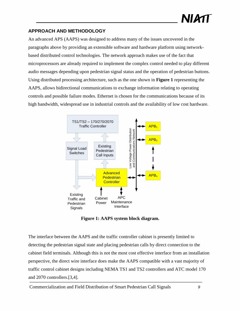
An advanced APS (AAPS) was designed to address many of the issues uncovered in the
paragraphs above by providing an extensible software and hardware platform using network-
based distributed control technologies. The network approach makes use of the fact that
microprocessors are already required to implement the complex control needed to play different
audio messages depending upon pedestrian signal status and the operation of pedestrian buttons.
Using distributed processing architecture, such as the one shown in Figure 1 representing the
AAPS, allows bidirectional communications to exchange information relating to operating
controls and possible failure modes. Ethernet is chosen for the communications because of its
high bandwidth, widespread use in industrial controls and the availability of low cost hardware.
TS1/TS2 – 170/270/2070
Traffic Controller
Signal Load
Switches
Existing
Traffic and
Pedestrian
Signals
Advanced
Pedestrian
Controller
Existing
Pedestrian
Call Inputs
Lo
w V
olta
ge
Po
we
r D
istr
ibu
tio
n
an
d C
om
mu
nic
atio
ns N
etw
ork
APB1
APB2
APBn
APC
Maintenance
Interface
Cabinet
Power
Figure 1: AAPS system block diagram.
The interface between the AAPS and the traffic controller cabinet is presently limited to
detecting the pedestrian signal state and placing pedestrian calls by direct connection to the
cabinet field terminals. Although this is not the most cost effective interface from an installation
perspective, the direct wire interface does make the AAPS compatible with a vast majority of
traffic control cabinet designs including NEMA TS1 and TS2 controllers and ATC model 170
and 2070 controllers.[3,4].

Commercialization and Field Distribution of Smart Pedestrian Call Signals 10
Although some of the operating features will be described in sections to follow, the hardware to
support the AAPS is highly scalable in both number of pedestrian buttons and the modes of
operation. The basic hardware and software are the result of research into application of
distributed systems concepts at the University of Idaho that has been reported on starting in 2006
[5,6,7]. It is customary in present pedestrian controls to parallel the inputs that control a common
set of pedestrian signals. Using a distributed approach, each pedestrian button is uniquely
distinguishable enabling the use of beaconing on one side of an intersection only.
The AAPS will be presented by focusing on three areas: operations and capability,
communications and information, and hardware design. The AAPS operations and capability is a
snap shot at one point in the development as the features are added to accommodate the needs of
specific traffic agencies. One of the significant qualities of the software centric distributed
processing based architecture is the ability thus far to accommodate the numerous revisions we
have been able to incorporate to date.
AAPS Operations
As previously described, there is a real-time control operations and near real-time supervisory
operations. The supervisory operations dictates how the AAPS is to operate based upon the
selection of options and configuration parameter values. Once the hardware has been installed,
all setup or tuning operations are completed by the Ethernet interface with the APC. The real-
time control operations will be discussed after the supervisory operations are described.
AAPS Supervisory Operations
All AAPS programmable configuration is completed using a web interface. The computer used
for maintenance and servicing does not require proprietary software; only a standard web
browser such as Internet Explorer®, Google Chrome®, or Mozilla Firefox®. The maintenance
and setup of the system uses web based controls through a web page that is hosted by the APC
single board computer.
The Advanced Accessible Pedestrian Management System (AAPMS) web page is organized into
an upper frame with fixed content and a bottom frame with variable content. The web page
organizes the data into three types: system operational status, configuration settings, and log
files. Status information includes the state of APC inputs and outputs as well as the state of all

Commercialization and Field Distribution of Smart Pedestrian Call Signals 11
APBs. Configuration settings are organized into two types: system wide and APB specific
settings. The contents of the various web pages will be discussed in detail to provide a systematic
approach to describing the functionality and capability of the AAPS.
AAPS Supervisory Operations - Status and Real-Time Monitoring
Figure 2 is a screen capture of the default web status page. The top frame of fixed content
presents system real-time status information of the pedestrian signals and pending pedestrian
calls waiting to be serviced. The pedestrian signal status line shows the state of the pedestrian
signal phases that are labeled A through H. Lettering the pedestrian phases on the AAPMS web
page eliminates confusion with the traffic controller phase assigned to the specific pedestrian
signals. Correlating the AAPS pedestrian phases and the traffic controller phases is completed in
software as well as wiring of the AAPS to the cabinet field terminals. For each AAPS phased A
through H, there are two conductors that are used to sense the on/off state of the 120VAC load
switches for the pedestrian signals associated with traffic phases.
Most traffic controller installations parallel the pedestrian button inputs such that multiple
pedestrian stations place a call on a single pedestrian phase. AAPS pedestrian stations have
unique network identification and the calls to the traffic controller must implement the parallel or
logic OR operation in software. Configuring the system that associates groups of pedestrian
buttons to a specific pedestrian call to the traffic controller is discussed below.
The status portion of the AAPMS also indicates what type of activation was used to generate the
call that is awaiting service if any. To the right of the signal and pedestrian call status lines is a
legend to explain the abbreviations used in the Signal Status boxes to help make the web page
self-documenting. The graphical picture to the right of the legend boxes is a diagram of the
intersection that illustrates the association of pedestrian stations number one through sixteen with
the pedestrian signal phases lettered A through H. The procedure for changing this diagram will
be discussed later in this document.
The real-time operating condition of each active button is established by communications
between the APC and each APB at a rate of four times each second. The text in the fields
associated with each pedestrian station will indicate ―OK‖ if the station is functioning properly
or ―BAD‖ if there is no or incorrect communications with the station. Inactive stations are blank

Commercialization and Field Distribution of Smart Pedestrian Call Signals 12
or shaded white and contain no text. Figure 2 shows the case when only stations three through
eight are configured to be part of the system for this application of the AAPS.
A constant call is asserted on the phase associated with pedestrian stations that are detected as
nonfunctional. Calls on all phases are placed on the traffic controller should the APC become
inoperative. APS that loose communications with the APC will reset to a benign non-functional
state until communications are re-established with the APC.
Figure 2: AAPS system status web page.

Commercialization and Field Distribution of Smart Pedestrian Call Signals 13
AAPS Operations – Pedestrian Station Operational Status
As stated above, the lower portion of the web page has variable content that is selected using the
row of seven tabs. Figure 2 shows the contents when the Status tab is selected displaying the
operational status of the individual pedestrian stations showing the pedestrian station operational
mode and activity history. The ―Audio Message #‖ line displays a number associated with the
audible message that is currently being played at each active pedestrian station. A legend that
explains the audible message numbers is shown at the bottom of the screen.
The data shown on the Ped Calls and APS Calls line is a running count of the number of calls
placed at the associated pedestrian stations. Although the AAPS can be programmed to do so, at
the present, there is no difference in the output signal to the traffic controller between normal
pedestrian calls and APS pedestrian calls produced by an extended press (EP-APS).
AAPS Operations – System Configuration
Besides the system Status frame, there are six other display options for the contents of the
bottom variable content frame of the service page: System (configuration), Station
(configuration), Sound Files, Network (properties), Time (configuration), and Log Files. Figure 3
shows the content of the system configuration. These settings are used to select the operating
modes for the APC and those APB options that are common to all stations.

Commercialization and Field Distribution of Smart Pedestrian Call Signals 14
Figure 3: System configuration page.
Configuration settings of the AAPS on the AAPMS web page are submitted using URL encoded
data. When the user submits configuration data via the AAPMS web page, a CGI scripts parses
the URL encoded data and processes it accordingly. First, the APC parses the incoming data and
Commercialization and Field Distribution of Smart Pedestrian Call Signals 15
saves it to non-volatile memory so that it will be retained during a power loss or system restart.
Then, the configuration data is applied to the different parts of the AAPS. For APC specific
configurations, the appropriate services are restarted, allowing them to re-read their specific
configuration files.
The series of sixteen boxes is used to select the stations that will be active as indicated by a
check in the box. Only the active stations can place a call and will play audible messages.
Previously active stations can be made inactive by clearing the check box. Adding a new station
to an AAPS requires the appropriate box to be first checked followed by a station configuration
as described below.
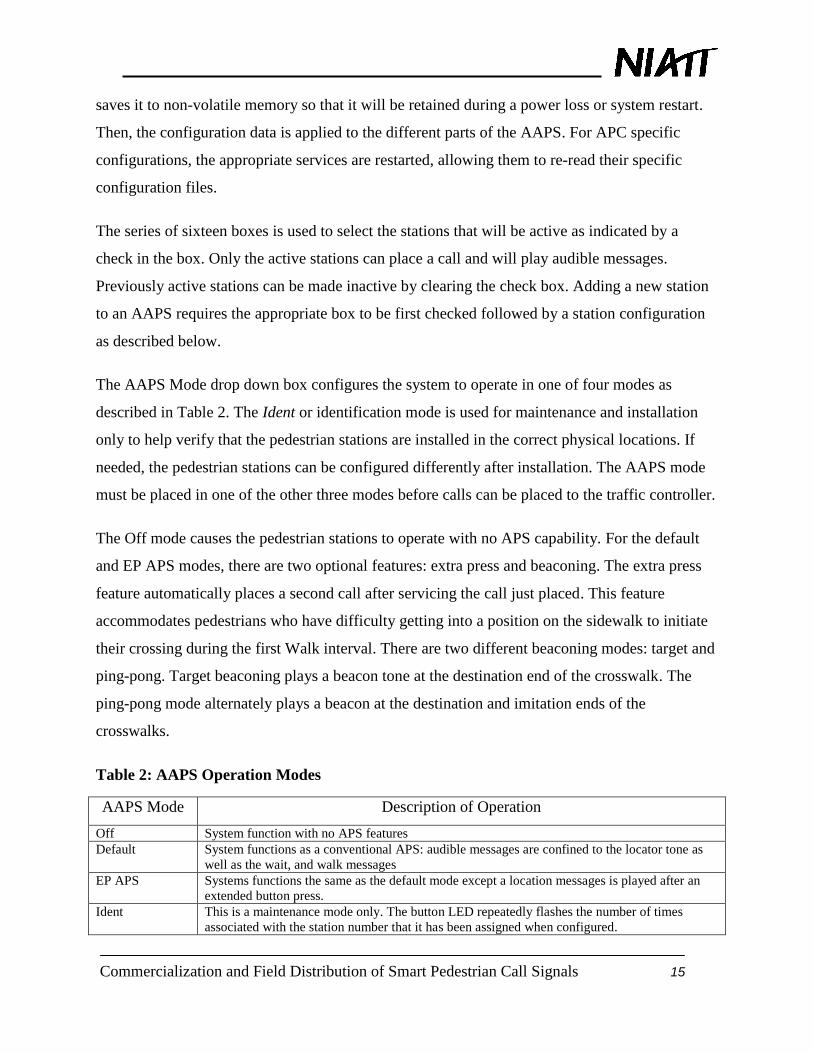
The AAPS Mode drop down box configures the system to operate in one of four modes as
described in Table 2. The Ident or identification mode is used for maintenance and installation
only to help verify that the pedestrian stations are installed in the correct physical locations. If
needed, the pedestrian stations can be configured differently after installation. The AAPS mode
must be placed in one of the other three modes before calls can be placed to the traffic controller.
The Off mode causes the pedestrian stations to operate with no APS capability. For the default
and EP APS modes, there are two optional features: extra press and beaconing. The extra press
feature automatically places a second call after servicing the call just placed. This feature
accommodates pedestrians who have difficulty getting into a position on the sidewalk to initiate
their crossing during the first Walk interval. There are two different beaconing modes: target and
ping-pong. Target beaconing plays a beacon tone at the destination end of the crosswalk. The
ping-pong mode alternately plays a beacon at the destination and imitation ends of the
crosswalks.
Table 2: AAPS Operation Modes
AAPS Mode Description of Operation
Off System function with no APS features
Default System functions as a conventional APS: audible messages are confined to the locator tone as
well as the wait, and walk messages
EP APS Systems functions the same as the default mode except a location messages is played after an
extended button press.
Ident This is a maintenance mode only. The button LED repeatedly flashes the number of times
associated with the station number that it has been assigned when configured.

Commercialization and Field Distribution of Smart Pedestrian Call Signals 16
In regards to noise pollution, the AAPS is capable of implementing a Night Mode operation
where the audible volume of the locator tone and speech messages can be adjusted to
accommodate both pedestrians and nearby residences and/or businesses. This option is enabled
on the system configuration web page as well as the active hours for night time operation. Table
3 defines five additional operating parameters for the AAPS. The automatic gain control (AGC)
responsiveness sets how quickly the volume is adjusted in response to a change in ambient
audible noise or interference.
The Walk Message Timeout specifies the duration of the walk message regardless of how long
the pedestrian walk signal is displayed. This setting is used for crosswalks that are served by a
rest-in-walk intersection operation where the pedestrian signal normally displays a walk
condition. The Walk Message Timeout terminates the audible walk message while the traffic
system is in the resting walk state unless initiated by a pedestrian button press. The locator tone
plays whenever the walk message is not playing.
The Repeated Wait setting indicates the delay time between wait messages that will be played
after the button is pressed while waiting for the walk signal. A value of zero indicates that the
wait audible message will be played only once each time the button is pressed.
Vibration Intensity allows the drive to the vibrotactile motor to be adjusted between zero which
corresponds to off to full intensity. For some installations, the mechanical vibrations are
amplified through resonance with the mounting structure and decreased motor drive is
appropriate.
Table 3: System Operating Parameters
Configuration
Parameter
Description
AGC
Responsiveness
Set the speed of volume adjust for changes to ambient audio noise. The range is from 0.1
seconds to 2 seconds.
Walk Message
Timeout
The length of time the walk message is played.
Extended Press
Time
Time the button must be pressed to activate the EP APS mode.
Repeated Wait The delay time in seconds between playing an audible wait message.
Vibration
Intensity
The intensity of vibration of the vibrotactile pedestrian button.

Commercialization and Field Distribution of Smart Pedestrian Call Signals 17
The Location and Intersection text boxes allow one to change the text that is displayed in the
upper fixed content web page. Any changes to the system configuration down to this point will
not be recorded unless the Submit System Configuration button is clicked on.
The graphical image shown in the top right of the web page is downloaded from the computer
viewing the web page to the AAPS server by first clicking on ―Choose File‖ and navigating to
the file location followed by clicking on the submit button.
Selecting the ―Reset‖ button on the Reset Counters line causes all of the station call counters
displayed on the Status web page to be reset to a count of zero.
Figure 4 and Figure 5 show web pages that are also associated with the system configuration. If
the AAPS is not connected to a WAN but directly to a PC or laptop computer, the default
network settings need not be changed. Additionally, direct connection with the AAPS
Maintenance port does not require a crossover Ethernet cable as the APC automatically makes
the appropriate connection. When connecting to a WAN, some or all entries on the Networking
page may require modification. These changes should only be completed by persons
knowledgeable of the WAN requirements.
Figure 4: System network properties page.
Figure 5 provides two methods for setting the real-time clock internal to the APC. The time can
be specified by completing the text boxes or by clicking on the ―Use Time from PC‖ box. The

Commercialization and Field Distribution of Smart Pedestrian Call Signals 18
later method copies the PC time into the text boxes. Using either method, the ―Submit Time
Configuration‖ button must be selected before the changes are transferred to the APC.
Figure 5: System time setup page.
AAPS Operations – Station Configuration
There are two web pages associated with configuring the individual pedestrian stations. The first
web page configures the individual station to be integrated into the system. The second web page
provides the capability for each individual pedestrian station to play up to eight unique audio
files associated to specific pedestrian movements. These parameters contained in these two pages
must be completed for every pedestrian station.
APB configuration options are handled much differently than system configurations. First, the
APB’s receiving new configurations are placed into a mode in which they are operable only at
the basic level, i.e.as a plain button. This is done so that as new configurations are loaded, button
operations are not affected. Next, the new configuration for that button is sent using the simple
network management protocol (SNMP) that will be discussed later in this report. Upon a
successful reconfiguration of the APB, it is placed into the received configuration.

Commercialization and Field Distribution of Smart Pedestrian Call Signals 19
AAPS Operations – Station Operating Parameters
Figure 6 provides the interface with the AAPS to configure an APB for a specific installation.
Each station is assigned a unique identification number between one and sixteen and a signal
phase that is used to determine the status of the pedestrian signals as well as the pedestrian call to
activate whenever a button is pressed. The APS group parameter associates pedestrian stations
that use common signal and call phases and must operate as pairs for beaconing.
The message and locator tone volumes of each station is set for both daytime and nighttime
operation (if used). The setting of zero corresponds to an audio level of 5db above ambient noise
level. Other values indicated on the volume scale are relative indications for reference only. The
―Submit Settings‖ button must be selected before the configurations will be sent to the pedestrian
station shown on the top line of this frame.
When changing the pedestrian station identification number or when first configuring a
pedestrian station that has not been previously configured, the ―Change Station ID‖ fields must
be specified. If the station has never been configured, the ―Old Station ID‖ defaults to a value
that is identified by the text ―New‖ that corresponds to a station ID of zero. Unless a pedestrian
station has been configured for an ID value between one and sixteen, no other parameters will be
accepted. Since all APBs have the same default identification number prior to configuration,
only one new station can be connected to the system at a time.

Commercialization and Field Distribution of Smart Pedestrian Call Signals 20
Figure 6: Station control page.
AAPS Operations – Audio File Management
Audio files are generated and stored on the service computer as ―.wav‖ files. The files are
transferred to the APC one at a time using the web link page shown in Figure 7. After receiving
each audio file, it is passed on to the specified APB using the file transfer protocol (FTP). FTP
uses the TCP/IP stack and creates a file system in the APB processor nonvolatile memory space.
Each file has a unique name that must match for the file to be played. These file names
correspond to the message that is being saved. The file names are wait, walk, location, locator,
initiation beacon tone (ibeacon), and destination beacon tone (dbeacon). In addition, there are
preempt and custom audio messages.

Commercialization and Field Distribution of Smart Pedestrian Call Signals 21
Figure 7: Sound file entry page.
The AAPS uses sound files in an 8bit 8 kHz pulse-code modulation (PCM) format. The sampling
rate and data word size is chosen as a balance between sound quality and file size. The human
voice contains frequencies that are primarily less than 4 kHz. Therefore, the 8 kHz sampling rate
is fast enough to capture human speech according to the Nyquist-Shannon Sampling Theorem
[8]. Eight data bits is the smallest word width in the PCM format but supplies enough resolution
to reproduce recorded speech. PCM was chosen because it requires the least amount of
processing by the device playing the sound. In PCM, the amplitude of the sound is recorded
directly. Therefore, the only processing required for playback may be volume control. With 8 bit,
16 kHz PCM audio, it ultimately requires 16kB of nonvolatile memory on the APB to store one
second of recorded audio.
Audio files are transferred to the APC using HTML multipart/form-data [9]. In this form, the
sound file and other fields of the form are packaged and sent to the APC web host and processed
Commercialization and Field Distribution of Smart Pedestrian Call Signals 22
by a common gateway interface (CGI) script. There are five fields sent to the APC web host:
stationid, fileid, resid, the sound file, and the submit field. The stationid field is what APB the
user selected to send the audio file to. Fileid is the number identifying which file is being sent.
Resid is a text string used by the AAPMS web page to notify the user of the status of each file
transfer. The submit field is the value of the parameter associated with the corresponding submit
button that was pressed. In the multipart-form transfer, each field is separated by a field
boundary. The boundary is browser and content specific and specified in the content header of
the transfer.
When the APC receives the HTML form data transfer, the first step is separating each field along
its boundary and storing the contents of each in the appropriate place. The AAPMS web page is
then notified about the file transfer. If the audio file was not in the correct format or the file or
station identification numbers are not valid, the web page notifies the user. Next, the sound file is
processed. To prepare the sound files for transmission to the APBs, the APC strips all of the file
information from the file to reduce the memory requirements. The resulting binary information is
only the PCM binary data. This file is then sent to the APB specified by stationid as file fileid. At
the beginning of the file transfer, the APB is placed into a silent mode so that no audio files are
accessed during a file upload. Upon a successful transfer, the AAPMS web page displays a
confirmation message to the user.
AAPS Operations – Fault Detection and Recovery
Fault detection for conventional pedestrian buttons is limited to ―stuck-on‖ failures. ―Stuck-off‖
failures are detectible only by monitoring the number of pedestrian calls to the traffic controller
over a period of time. Failure detection for pedestrian controls is one of the major innovations of
AAPS.
Being a distributed processing system, failures can occur at each of the APB installations and at
the APC in the traffic controller cabinet. The distribution of information is critical to correct
operation. Each APB expects a packet of information from the APC each 250ms. Any APB that
miss two successive packets from the APC will go into fault operation where all audible
messages are terminated and no calls are sent to the APC should the button be pressed while in

Commercialization and Field Distribution of Smart Pedestrian Call Signals 23
this mode. An APB that is operating in the fault mode continues to listen for packets from the
APC and if communications is restored, the APB resumes normal operation.
Each time the APC sends a packet to an APB, an immediate response is expected. The APB
response packet contains information regarding the current activity of the APB including the
number of the audible message being played. The organization of the audible messages is such
that only certain audible messages are compatible with a given set of pedestrian signal states.
The compatibility mapping illustrated in Table 4 is checked in a manner similar to the
programming card in a conventional MMU or CM. For each station, a parameter containing the
message ID is sent to the APC. The current state of the pedestrian signal phase is logically tested
using a logical AND operation in the computer program. If the result is zero or logical FALSE
hence a system failure is detected. For example, the Wait message is only compatible with the
FDW and DW pedestrian signal states as noted by the value of one in those columns.
Table 4: AAPS Malfunction Compatibility Table
ABP State Pedestrian Signal State
Message ID W FDW DW PreEmpt
Locator 1 1 1 1 0
Ibeacon 2 0 1 0 0
Dbeacon 4 0 1 0 0
Wait 8 0 1 1 0
Walk 16 1 0 0 0
Location 32 0 1 1 0
Custom 64 0 0 0 0
Preempt 128 0 0 0 1
If this response is not received, the failure is logged and the web page updated to identify which
APBs have failed to communicate. Additionally, a constant call is sent to the traffic controller on
the phase that the particular APB has been configured. Should the APC loose power or fail to
reset properly, constant calls are placed on all call output to the traffic controller. The APC and
all APBs are programmed to fail in the safest output state and continually attempt to restore the
system to full operation. There is no direct interface between the AAPS fault detection and the
traffic controller CM or MMU.

Commercialization and Field Distribution of Smart Pedestrian Call Signals 24
NETWORK COMMUNICATIONS
The AAPS is designed around a distributed processing architecture and two independent
Ethernet based networks: the real-time operations network and the supervisory network. The
supervisory network uses a web based human-machine interface that operates in near real-time
for indicating system status and supports making configuration changes to the AAPS. This
network that is depicted as the APC Maintenance Interface in Figure 1 can connect directly to a
PC or laptop, or it can connect remotely over a wide area network (WAN) infrastructure.
The real-time operation also uses Ethernet technology to implement a local area network (LAN).
The LAN provides communications for sending the pedestrian signal status sensed by the APC
to all active pedestrian stations, detecting failed pedestrian stations, and relaying pedestrian calls
to the traffic controller whenever a pedestrian button is pressed. The real-time network uses a
protocol that is structured following the NTCIP guidelines. The LAN is also used in a non-real-
time mode for configuring individual pedestrian stations during setup and maintenance.
System Operations – Communications
Since the AAPS is a standalone system and operates on an isolated network, any network
protocol could have been used. In order to allow future integration with NEMA TS2 traffic
controllers, we chose to implement the AAPS using NTCIP. We recognized that many of the
objects we needed are not included in the NTCIP 1202 guide, and hence we developed a specific
set of objects which are described below [10,11,12]. A significant portion of the communications
protocol used to implement the AAPS is based upon work reported on by Devoe, et.al. [13].
It is recognized that NTCIP was developed to provide supervisory level communications
between a traffic control center and traffic controllers at the intersection. As noted by Paul Olson
from FWHA in private communications, ―NTCIP has not been defined or otherwise targeted to
communications between the traffic signal controller and any devices within the cabinet and field
devices. This has a significant impact on this paper as it is a totally new approach to the traffic
signal controller/cabinet architecture.‖
Ethernet Implementation to support NTCIP
The Ethernet stack is a software model provides the lower levels of the Ethernet protocol up to
the transmission control protocol (TCP) and user data protocol (UDP) layers. The simple

Commercialization and Field Distribution of Smart Pedestrian Call Signals 25
network management protocol (SNMP) layer will use this stack to access the UDP protocol. The
SNMP objects provide a means to address and change objects that are used to control the
operation of the system. Figure 8 is a partially modified diagram of the NTCIP Standards
Framework that the AAPS implements by adding EoP to the physical layer along with the
twisted pair. The heavy solid lines represent the data path for the operational portion of the
AAPS. The lighter solid line represents the data path used for transferring audio speech and tone
files from the APC and the individual APBs.
ITS Data
Model
ITS Data
Dictionary
ITS Mesasage
Set
Reference
Model
Files
TFTPFTPCOBRA DATEX
TCP UDP
Data Objects
Dynamic
Objects
STMPSNMP
IP
Ethernet
Twisted
PairEoP
Figure 8: Partial NTCIP standards framework.
SNMPv1
SNMP was developed in the 1980’s by the International Engineering Task Force (IETF) to
provide standard extensible management of local area network based products [14]. Even though
SNMP has been updated to version 3, our use is limited to operation of version 1. Version 1
provides the communication protocol necessary for the operation of the system.

Commercialization and Field Distribution of Smart Pedestrian Call Signals 26
For our system, all of the functions of the SNMP protocol are supported but not necessarily used.
The SNMP messages enable the APC to validate this communication with each APB and that
each APB is capable of verifying that a call has been placed to the APC. For normal operation,
the APC periodically generates a SetRequest message that updates each system APB that in turn
responds back to the APC a GetResponse message. This exchange of information provides
verification to the APC that each APB is operational and has received the correct information.
When a user has pressed a pedestrian button, the station APB sends a Trap message to the APC.
A Trap is an unsolicited message generated by the APB that the APC does not respond to. The
Trap is verified received on the next received ―SetRequest‖ message. If the next ―SetRequest‖
message from the APC does not indicate that a call has been placed, the APB will generate
another Trap.
The program, Wireshark [15] was instrumental as a development tool for designing the
applications programs to build the SNMP frame. It displays individual packets in real time as
they occur on the Ethernet physical layer. In its display, it breaks the packets down in user
identifiable layers as well as the actual hexadecimal bytes in the packet.
SNMP OID’s
SNMP Protocol Data Unit’s (PDU) are used to manipulate values. These values are described by
Object Identifiers (OID). An OID uniquely describe the value. NTCIP 1202[11] describes the
OID’s that involve traffic controllers. NTCIP 1202 does not provide adequate objects to support
the operation of the AAPS system hence we generated our own set of custom objects. For our
research, the selection of the set of OIDs is of no consequence because there is no direct
interaction between the AAPS network and any network that the traffic controller is connected
to.
However, as an exercise, the root OID was defined following the guideline specified by NTCIP
8004 [12]. As shown in Table 5, the root OID is ―1.3.1.4.1.1206.4.2.14‖. Figure 9 is helpful to
understanding the architecture on Management Information Base (MIB) objects. The digits
―1.3.1.4.1.1206‖ refer to all NTCIP SNMP MIB objects. The next digit, ―4‖ was chosen because
the pedestrian button is a transportation related device. For our implementation, it may be more
appropriate to have specified a value of ―2‖ indicating that AAPS is a NEMA experimental

Commercialization and Field Distribution of Smart Pedestrian Call Signals 27
device. However, once the AAPS becomes a commercial product, the manufacturer can either
apply for a private identifier, hence, the seventh digit would be a ―3‖ or apply to NEMA to have
pedestrian control devices assigned public device node value resulting in the value of ―4‖. For
our exercise, we chose to assume that the last scenario is the case.
The eight digit which has a value of ―2‖ designated that the object refers to a device. The last
digit in the root MIB OID has been specifically assigned to a value of ―14‖ so not conflict with
any of the 11 current device nodes registered under NEMA transportation devices.
NEMA
1206
Management
1
Experimental
2
Private
3
Transportation
4
TCP/IP
3
Protocols
1
Devices
2
Pedestrian
Controls
14
Actuated Signal
Controller
1
Priority Request
11...
Figure 9: MIB tree for major NTCIP nodes.
The SNMP OID’s that are needed for operation of the AAPS system are described in Table 5
through Table 7 below. The Status Node OID’s are the objects that are sent from the APC to
each APB at periodic intervals.

Commercialization and Field Distribution of Smart Pedestrian Call Signals 28
Table 5: Status OID Definitions
Node OID Type Description
APB device ode 1.3.1.4.1.1206.4.2.14
Root node for APBS, 14 on end may
change
Phase Status Node APB.2 Bits
Phase Status Don't Walks APB.2.1 Bits
Bits. If set to 1 that phase is in the
don't walk state
Phase status Ped Clears APB.2.2 Bits
Bits. If set to 1 that phase is in the
Ped clear state
Phase Status Walks APB.2.3 Bits
Bits. If set to 1 that phase is in the
Walk state
Phase Status Calls APB.2.4 Bits
Bits. If set to 1 that phase has a call
pending
Phase Status APS Calls APB.2.5 Bits
Bits. If set to 1 that phase has an
APS call pending
Phase Status Beacon Source APB.2.6 Bits The source of an APS call
Phase Status Beacon Destination APB.2.7 Bits The Destination of an APS call
Phase Status Block Object APB.2.8 OS
Octet string containing all of the
phase status objects
Station Status Node APB.3
Station Audio Message APB.3.1 Int
Audio message currently being
played
SNMP Trap
The SNMP trap PDU is required to contain two items: the system up time or time since its last
reboot and the SNMP Trap OID. Any additional information can be added beyond the required
OID’s. The APB will add either a Phase Status Calls or APS Calls OID depending on the type of
input detected from the user of the button to the trap message. Each APB will use its
preconfigured Station Phase OID value or Station Group OID value in the value field depending
upon the type of trap that is generated. Table 6 contains the list of objects that are sent when a
SNMP trap is sent from the APB to the APC.

Commercialization and Field Distribution of Smart Pedestrian Call Signals 29
Table 6: Station Trap OID's Definitions for AAPS
Node OID Type Description
Device OID 1.3.6.1.6.3.1.1.4.1 OID SNMP Trap OID
System up time 1.3.6.1.2.1.3.0 OS Octet string of system up time
SNMP Trap 1.3.6.1.6.3.1.1.4.1.0 Int
Phase Status Calls APB.2.4 Bits
Bits. If set to 1 that phase has a call
pending
Phase Status APS
Calls APB.2.5 Bits
Bits. If set to 1 that phase has an
APS call pending
APB Configuration Objects
The Configuration OID variables are also set using the SNMP protocol. These variables are
configured once unlike the Status objects, therefore these objects are saved to nonvolatile
memory. This allows for the system to recover from a power loss with no loss in service. Table 7
describes the configuration information for each button. Each APB is initially programmed with
default values for each OID. The default values allow a new button to be found when added to
the network. This means that all buttons are programmed exactly alike and then configured to be
unique in the system using the maintenance web interface.

Commercialization and Field Distribution of Smart Pedestrian Call Signals 30
Table 7: Configuration OID Definitions for AAPS
Node OID Type Description
APB device node 1.3.1.4.1.1206.4.2.14
Root node for APBS, 14 on end
may change
Station ID APB.1.1 Int
Station ID number. Values 1-16
(0 for not configured)
Station Night Mode APB.1.2 Int 1 If night mode is on
Station Day Locator Volume APB.1.3 Int Values 0-100
Station Day Speech Volume APB.1.4 Int Values 0-100
Station Night Locator Volume APB.1.5 Int Values 0-100
Station Night Speech
Volume APB.1.6 Int Values 0-100
Station IP Address APB.1.7 OS
4 byte octet string of the
stations IP address
Station Mode APB.1.8 Int 0-4 AAPS operation Mode
Station Identify APB.1.9 Int
0 for identify off. 1 for
LED blink/vib
Station Phase APB.1.10 Bits
Bit corresponds to
Station's phase
Station Group APB.1.11 Bits
Bit corresponds to
Station's Group
Station Beacon Mode APB.1.12 Int
AAPS Beacon operational
Mode
AAPS HARDWARE
Figure 1shows the system architecture for the AAPS system. The hardware consists of an
advanced pedestrian controller (APC) and one or more advanced pedestrian buttons (APB)
connected by a low voltage power conductor and a common ground or reference conductor. The
APC interfaces with the traffic controller cabinet using existing field wiring terminals. The APC
senses the pedestrian signal status by monitoring the 120 alternating current voltage (VAC) load
switch outputs. Pedestrian calls are placed using the conventional terminals for pedestrian button

Commercialization and Field Distribution of Smart Pedestrian Call Signals 31
inputs. Although not shown in Figure 1, it is possible to simultaneously operate both
conventional APS and AAPS pedestrian stations provided the AAPS stations and conventional
pedestrian stations use separate conductors.
The AAPS is powered from 120 VAC supplied to power the traffic controller cabinet. The 120
VAC is stepped down to a nominal 12 to 18 VAC to power the APC and all APB stations. The
communications is implemented using Ethernet over power line (EoP) technology over the 12-
18VAC conductors distributed to the APBs.
The APC maintenance interface is an independent Ethernet connection to a service computer for
installation and maintenance. The function of this interface will be discussed later in this report.
Advance Pedestrian Controller
As shown in Figure 10, the APC consists of a commercial of-the-shelf Linux based single board
computer with a 70 MHz ARM 7 microprocessor and a traffic cabinet interface board of
proprietary design. All interfaces with the traffic controller cabinet use optical isolation and
transient protection components. The system is capable of interfacing with eight pedestrian
signal pairs to sense the 120 VAC W and DW load switch outputs.
An 18 LED array is the only local display that indicates APB failures. All other human-machine
interface (HMI) is via the second Ethernet port connected to a service computer or laptop
computer. The simple HMI on the APC eliminates the cost and space otherwise needed to
support wide temperature range LCD displays and key panels. The Ethernet interface will be
described later in this paper. A real-time clock with battery backup is provided to support an
optional time of day operation.
The network interface uses a SM5560 EoP modem that supports the 85 Mbps Ethernet using the
HomePlug ® 1.0 standard [16, 17]. Similar devices are commercially available that operate on
120 to 220 VAC and are not available to operate at low voltages. Our proprietary design is
needed for the AAPS system to operate on the 12 to 24 VAC power that is used to power the
pedestrian stations.

Commercialization and Field Distribution of Smart Pedestrian Call Signals 32
AVR32
Linux Based
Single Board
Computer
AC
Sensor
AC/DC
Switch
Service
Computer
EoP
Modem
Power
Supply12-24
VAC
120VAC
APC
Ethernet
Port #1
Ethernet
Port #2
Clock
LED
Panel
Traffic
Controller
Pedestrian
Button
Inputs
Pedestrian
Signal Load
Switch
Outputs
Figure 10: Block diagram of an advanced pedestrian controller.
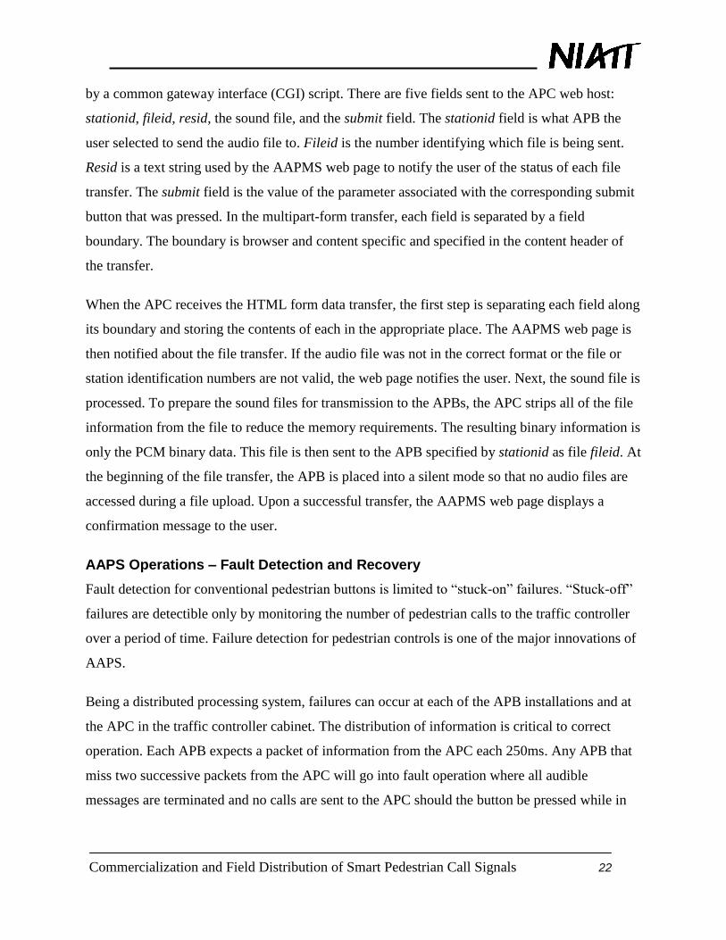
Advanced Pedestrian Button
The block diagram for the proprietary APB electronics is shown in Figure 11. The APB uses a
NXP LPC2468 processor based upon a 32 bit, 72 MHz ARM 7 processor architecture. This
particular processor was chosen because it supported a media independent interface (MII) needed
to communicate with the EoP modem and the 512 kB processor flash memory that can be used to
store audio messages.
Apart from the communications, only six pins of the 208 processor pins are needed for input and
output. Two inputs are for the audio microphone used for ambient noise compensation and the
pedestrian pushbutton itself. The three outputs are used for a call acknowledge indication LED,
the vibrotactile control output, the audio output for the speech messages, and a test output for
remotely placing a pedestrian call. The MII interface for the EoP communications requires 18
processor pins.
On the surface, the processor chosen appears to be more than required for this application.
However, the functionality designed into the NXP processor reduced system cost and physical
size of the APB circuit board. The APB IO consists of two analog outputs, one digital output,
one analog input, and one digital input. One analog output is used to drive the speaker for the
audible messages. The second analog output is in the form of a pulse width modulation (PWM)
control of the vibrotactile button plate for vibration intensity control. A digital output to an LED
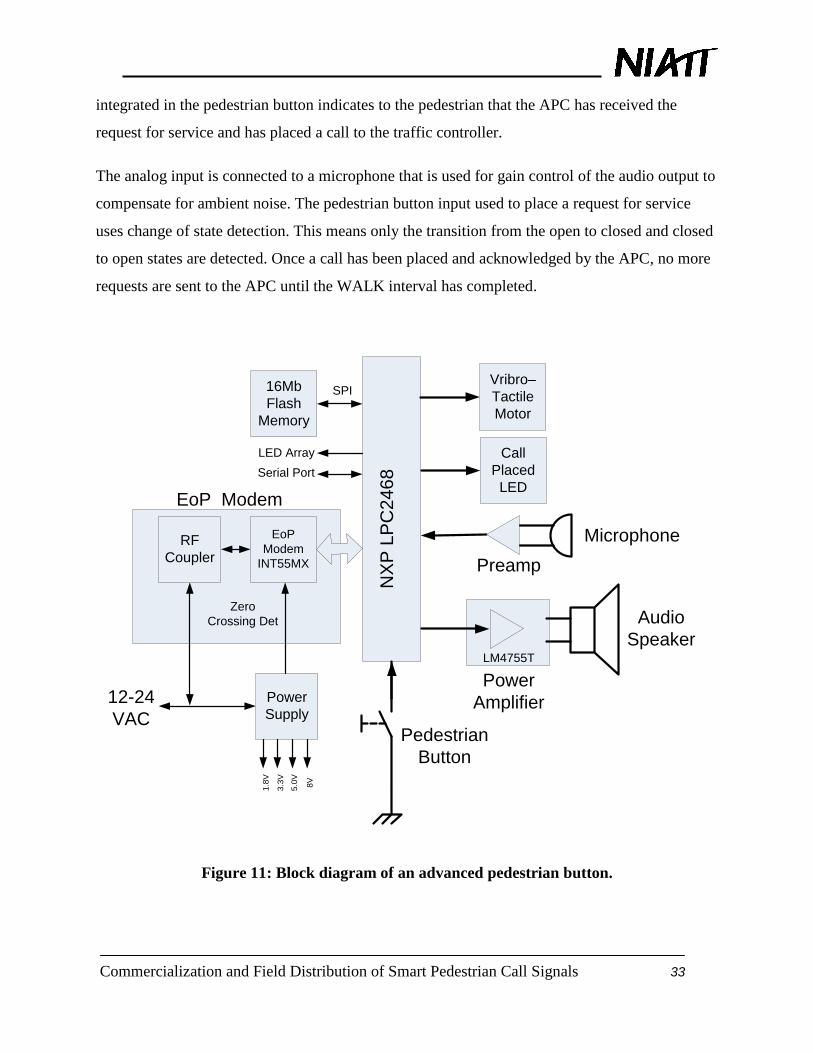
Commercialization and Field Distribution of Smart Pedestrian Call Signals 33
integrated in the pedestrian button indicates to the pedestrian that the APC has received the
request for service and has placed a call to the traffic controller.
The analog input is connected to a microphone that is used for gain control of the audio output to
compensate for ambient noise. The pedestrian button input used to place a request for service
uses change of state detection. This means only the transition from the open to closed and closed
to open states are detected. Once a call has been placed and acknowledged by the APC, no more
requests are sent to the APC until the WALK interval has completed.
Audio
Speaker
Power
Amplifier
EoP
Modem
INT55MX
Pedestrian
Button
Microphone
Power
Supply
LM4755T
12-24
VAC
RF
Coupler
NX
P L
PC
24
68
Vribro–
Tactile
Motor
Zero
Crossing Det
1.8
V
3.3
V
5.0
V
8V
Serial Port
EoP Modem
Call
Placed
LED
LED Array
Preamp
16Mb
Flash
Memory
SPI
Figure 11: Block diagram of an advanced pedestrian button.

Commercialization and Field Distribution of Smart Pedestrian Call Signals 34
AAPS – Future Research
The AAPS was designed to provide infrastructure support for advanced features such as the
ability to integrate remote pedestrian controls to enhance the accessibility for mobility and
visually impaired pedestrians [18]. We have tested such a system that can place pedestrian calls,
provide navigational aids to help pedestrians stay within the crosswalk, and allow the traffic
controller to track the pedestrian’s progress across the intersection. New cell phone and personal
communications technology devices that have become available even within the past year makes
the remote operation more feasible by overcoming position accuracy and range short comings
previously experienced.
Although the 2009 edition of the MUTCD allows, based on dialogs with human factors
professors at the University of Idaho, we do not recommend operating with the beaconing feature
active. The variability of the acoustical environment hinders the repeatability and reliability of
the audible tones for navigation use. Presently, the orientation of the pedestrian button and the
speakers are designed to guide low-vision pedestrian to locate the button; not the destination end
of the crosswalk. To be effective, the volume of the beacon tone must project across the entire
length of the crosswalk and must remain on the entire time of the walk and flashing don’t walk
intervals. The later has a high potential for complaints of noise pollution. Certainly this is an area
that requires additional study in order to be safe and effective.
As noted in the discussion of the AAPS fault detection and recovery, there is no direct interface
between the AAPS and traffic cabinet MMU or CM. Current intersection operations specify that
if a conflict is detected, all traffic signals will flash the red signal and all pedestrian signals will
be turned off defaulting to an all-way stop with a pedestrian crosswalk. Prudence dictates that the
pedestrian signals should be checked for conflicts along with the traffic signals. Since the audible
messages serve the same function for controlling pedestrian movement as pedestrian signals do
for sighted pedestrians, it is logical that the audible message compatibility should become part of
the overall MMU operations. Research is needed to determine the most effective way to
implement the fault detection.
Pedestrian button failures present potentially hazardous conditions that result from pedestrians
deciding that he or she must take risks to make a street crossing in violation to the indication of

Commercialization and Field Distribution of Smart Pedestrian Call Signals 35
the pedestrian signals. The lack of responsiveness to a pedestrian call is source of frustration and
serves to undermine the confidence in even functional pedestrian call systems. The fault previous
detection and recovery discussion addresses the operations of the electronic components and the
software program code. However, the fault coverage as determined by the percentage of the
system that is testable is limited to conditions that are observable on the inputs of the processors.
Failure detection for mechanical inputs and outputs may require analysis of operating patterns.
Regardless of the techniques used to detect and mitigate failures, they may require significant
additional software and possibly additional hardware to achieve the desired system fault
coverage which can ultimately reduce the overall system availability. There is also the issue of
who is checking the checker that is not addressed. Although the following proposed fault
detection schemes have not been implemented, the existing hardware can support most if not all
of the approaches. The following discussion does not address the mitigation of detected failures
but must also be considered when adding the detection capability. To quote an unknown source,
―There is no use in taking a measurement that provides information that is not used.‖
Electric signals are more easily monitored and allow the use of separate electronics for
independent verification. NEMA TS2 type controllers have the ability to present the signal state
in multiple formats: the AC voltage from the load switches, the messages on the Synchronous
Data Link Control (SDLC) serial bus, and the NTCIP objects available over the Ethernet
connection to the traffic controller. Using either the SDLC serial bus or Ethernet port, the APC
can confirm that a pedestrian call output to the traffic controller has indeed been placed.
Similarly, the pedestrian signal detection can be detected by comparing the inputs from the
connections to the load switch outputs with the data available via the SDLC serial bus or
Ethernet connection.
Inputs and outputs with which humans interact are inherently difficult to observe using
automation and usually require special instrumentation. APS involve three of the five human
senses to communicate the states of the pedestrian signals. The APB has three outputs for
interface to pedestrians: the visual output in the form of an LED that indicates that a call has
been place, a vibrotactile surface on the button that indicates that the WALK interval is in
progress, and the audible output that indicates the pedestrian button location and the state of the
pedestrian signals.

Commercialization and Field Distribution of Smart Pedestrian Call Signals 36
The LED indication that a call has been placed is provided to give user confidence that the
system recognized the button press, and that he or she will be given service in due course of the
operation of the intersection. LED devices have such a low failure rate and a minimal risk to
human safety because of a burned out LED, that the added expense to confirm that the LED can
emit light does not appear to be economically justifiable. However, identifying a low-cost
detector and an efficient means of implementing the detection could have far reaching effects for
LED traffic and pedestrian signals.
The mechanical vibrations from the vibrotactile button can be detected using an accelerometer.
This solution requires additional electronics for the transducer and signal conditioning.
Certainly the audible output is the most critical output particularly for low vision pedestrians. A
possible means of observing the audio output is to use the microphone that is used by the APB
for volume compensation due to ambient noise. The audio feedback can be used to detect a
volume level from the speaker or implement a pattern recognition algorithm to correlate the
microphone feedback to the input to the analog signal that is sent to the power amplifier.
Testing the APB inputs can be accomplished using the latest hardware design. As discussed
above, the microphone can be used to sense the output from the speaker. The only issue with this
approach is differentiating between a failure in the audio output electronics and the audio input
electronics. However, since the audio system relies on both operating correctly, the importance is
in the detection of a failure in the audio system and not necessarily of failed component
identification.
The latest version of the APB electronics circuit board has the capability of remotely activating
the pedestrian button input. A transistor has been added that operates in parallel with the
pedestrian button such that it can be controlled to short the pedestrian button input. This
capability allows both remote and local automated pedestrian button operation. The remote
pedestrian button activation appears to have some interest by traffic agency technicians and
engineers. The remote button operation capability can detect buttons that fail in the pressed state
and shorted button wires. A button that has failed in the open state is detectible by observing the
use history as indicated by the APC call count registers. Another possible solution is to alter the
mechanical design of the pedestrian button to operate as the classical form C contact where the

Commercialization and Field Distribution of Smart Pedestrian Call Signals 37
button has two outputs: one for the pressed condition and one for the relaxed condition.
Unfortunately, the mechanical integrity of the button itself remains outside the fault coverage for
current button designs.
Future research is planned to identify remaining failure modes and the cost to implement the
various detection schemes. Based on AAPS operating experience and advice from traffic
operation practitioners, a priority list will be established and the additional fault coverage will be
systematically expanded. Safety and expense are the top criteria when establishing a priority list.

Commercialization and Field Distribution of Smart Pedestrian Call Signals 38
FINDINGS; CONCLUSIONS; RECOMMENDATIONS
The additional requirements to accommodate pedestrians with a wide range of physical and
visual disabilities results in a highly complex set of controls. The audible messages provided by
APS have the same level of need for accuracy and consistence as do visual pedestrian signals.
The numerous intricate traffic system operating modes must be precisely integrated with both
visual and audible pedestrian signals resulting in multifaceted computer programs with many
operating parameters.
The approach to the AAPS design was to provide an extensible architecture that allows for easy
integration of enhanced features and operating modes. A web interface eliminates the need for
application specific PC software for system maintenance and diagnostics. The system logs
maintenance operations and system failures which can be archived for system documentation.
The web interface allows one person to view the entire system operations from one location.
Using network communications enables observations of operations for microprocessors located
outside the traffic controller cabinet. Audio files that are played at each pedestrian station are
compared to be consistent with the pedestrian signal status. Each communications transaction is
verified to detect equipment and wiring errors as well as communication errors. The constant
communications allows the system to detect pedestrian station failures at the traffic controller
cabinet even when there is no pedestrian button activity. Using an industry standard network
protocol allows the interoperability with future and present traffic control devices.
The AAPS presented in this report uses a hardware architecture that has the capability to meet
the expanding requirements of APS systems. A system that uniquely identifies each pedestrian
station can now be programmed so that pairs of pedestrian stations can operate in concert to
facilitate beaconing with no additional wiring. Time of day operation can be used to reduce
volume depending upon local requirements.
It is apparent that the existing AAPS is capable of performing a higher level of self-testing than
is currently implemented. The AAPS software, hardware, and method of communication are
specifically designed with the capability to expand the functionality. There are numerous
approaches that are considered for future research in improving the reliability and safety of
accessible pedestrian systems by expanding the fault detection coverage.

Commercialization and Field Distribution of Smart Pedestrian Call Signals 39
REFERENCES
[1] ―Traffic Signal Timing Manual‖, Section 5.3,
http://ops.fhwa.dot.gov/publications/fhwahop08024/chapter5.htm#5.3, last access on June 4, 2010.
[2] Harkey, D.L., Carter, D.L., Barlow, J.M. and Bentzen, B.L. (2007) Accessible Pedestrian Signals: A Guide to
Best Practice. NCHRP Web-Only Document 117A, http://onlinepubs.trb.org/onlinepubs/nchrp/nchrp_w117b.pdf,
last viewed on July 20, 2009
[3] Noyce, D.A. and J.M. Barlow,―Interfacing Accessible Pedestrian Signals (APS) with Traffic Signal Control
Equipment‖, April 2003, available at http://www.access-board.gov/research/aps/report.pdf, last access on June 10,
2010.
[4] Traffic Detector Handbook:Third Edition—Volume I, Publication No. FHWA-HRT-06-108, October 2006,
Section 3-42, available at http://www.tfhrc.gov/its/pubs/06108/06108.pdf, last accessed on June 10, 2010
[5] Wall, R.W., A. Huska*, and D. Bullock, ―Application of Plug and Play Distributed Signal Technology to Traffic
Signals,‖ Transportation Research Board 2006 Annual Meeting, Washington D.C., January 22-26, 2006, Paper No.
06-2728.
[6] Wall, R.W., T. Urbanik, D. Bullock, S. Allen*, M. Busby*, D. DeVoe*, A. Huska*, T. Rallens* ―Distributed
Traffic Signal Control: Improving Pedestrian Control as A First Step‖, Transportation Research Board 2007 Annual
Meeting, Washington D.C. January 21-25, 2007, Paper No. 07-0989
[7] DeRuwe, G.* and R. W. Wall, ―Pedestrian Navigation and Integration with Distributed Smart Signal Traffic
Controls ‖, The 34th Annual Conference of the IEEE Industrial Electronics Society, Orlando, FL, November 11,
2008, Paper # HD-010979
[8] L.B. Jackson, Digital Filters and Signal Processing‖ 3rd
Ed.Kluwer Academic Publishers, 101 Philip Drive,
Assinippi Park, Norwell, MA, 02061, ISBN 0-7923-9559-X, page 156. [8] URL-encoded and multipart forms
http://www.w3.org/TR/html4/interact/forms.html#h-17.13.4.1, last viewed on July 20, 2009
[9] ―RFC2388 - Returning Values from Forms: multipart/form-data‖, available at
http://www.faqs.org/rfcs/rfc2388.html, last accessed on June 9, 2010.
[10] ―NTCIP 9001, National Transportation Communications for ITS Protocol – The NTCIP Guide‖, A
Recommended Information Report of the Joint Committee on the NTCIP, July 2009, available at
http://www.ntcip.org/library/documents/pdf/9001v0406r.pdf, last accessed on June 10, 2010.
[11] NTCIP 1202 v1.07 National Transportation Communications for ITS Protocol Object Definitions for Actuated
Traffic Signal Controller (ASC) Units . Washington: Institute of Transportation Engineers, 1/31/2007, available
http://www.ntcip.org/library/standards/default.asp?documents=yes&qreport=no&standard=1202, last accessed on
June 10, 2010
[12] ―NTCIP 7001 – Assigned Numbers Summary‖, Washington: Institute of Transportation Engineers, available at
http://www.ntcip.org/library/standards/default.asp?documents=yes&qreport=no&standard=7001, last accessed on
June 10, 2010
[13] DeVoe, D.* and R.W. Wall, ―A Distributed Ethernet Network of Advanced Pedestrian Signals‖, The 88th
Annual Meeting of the Transportation Research Board, Washington, DC, January 11-15, 2009
[14] Case, J., M. Rose, S. Waldbusser, ―Protocol Operations for version 2 of the Simple Network Management
Protocol (SNMPv2)‖, "RFC:1448." 1993, available at http://tools.ietf.org/html/rfc1448, last viewed on July 20, 2009

Commercialization and Field Distribution of Smart Pedestrian Call Signals 40
[15] Wireshark network packet analyzer, available at http://www.wireshark.org/download.html. Last accessed on
April 15, 2010
[ 16] SM5500 product sheet, Aasoka, available at
http://www.sequoia.co.uk/components/product.php?d=1&c=14&f=5&p=557&fmt=grid, last viewed on June 20,
2010
[ 17] HomePlug 1.0 Technology White Paper, available at
http://www.homeplug.org/tech/whitepapers/HP_1.0_TechnicalWhitePaper_FINAL.pdf, last
viewed on June 20, 2010
[18] Gabriel DeRuwe, ―Smart Signals Pedestrian Controls for the Vision Impaired‖, Masters of Science Thesis,
University of Idaho, May, 2009