commercial, stiffened, farm & hopper - sukup · pdf file ·...
TRANSCRIPT

BIN OPERATION MANUAL COMMERCIAL, STIFFENED,
FARM & HOPPER
1555 255th Street, Box 677 Sheffield, Iowa, USA 50475-0677
Phone: 641-892-4222 Fax: 641-892-4629
Website: www.sukup.com Email: [email protected]
Arcola, IL Aurora, NE Defiance, OH Jonesboro, AR Cameron, MO Watertown, SD 217-268-3026 402-694-5922 419-784-9871 870-932-7547 816-649-2226 605-822-6697 F: 217-268-3522 F: 402-694-5921 F: 419-784-9872 F: 870-933-8946 F: 816-249-2227 F: 605-884-0467 Manual L13920 © Sukup Manufacturing Co. 04/05/2018

Thank you for purchasing Sukup equipment.
At Sukup Manufacturing Co., we strive to provide our customers with the best products available. It’s
important to us that you get the best value for your money. That means producing top-quality products that will provide you with many years of satisfied ownership.
We back our products with experienced staff and the best customer service in the industry. Our dedicated employees have done their best to ensure that your
Sukup equipment will meet your needs. With proper installation and use, it will serve you for many years.
If for some reason you experience difficulties with your
Sukup equipment, your authorized Sukup dealer can provide you with the help you need. If you need
assistance beyond what your dealer can provide, you can always contact your regional Sukup Distribution Center
or our headquarters in Sheffield, Iowa, USA.
Thank you again for your purchase. We wish you many years of profitable, safe use of your Sukup equipment.
Eugene, Charles, Steve and The Entire Sukup Family
Sukup Manufacturing Co.
Sheffield, Iowa, USA
2

Table of Contents
Warranty Limited Warranty 5 Initial Guidelines 6
Safety Recognizing Safety Decal Information 7 General Operational Safety Procedures 8 Dangers of Entering a Grain Bin; Flowing & Crusted Grain 9 Bridged & Caked Grain 10 Moving Parts 11 Lockout/Tagout; Ventilation; Sharp Edges & Obstacles 12 Falls & Obstructions; Ladder Safety 13 Fall Restraints & Arrest Systems 14 Knot-Passing Pulley & Restraint Anchor 15 Top Causes of Bin Failure 16 Construction Safety 17
Planning Preparations Site Selection 18 Electrical Wire Clearance 19 Component Location 20 Selecting Builders & Contractors; Foundation 21 Anchor Bolt Guidelines 22-26
Bin Operation & Management Bin Description 27 Bin Usage 28 Initial Fill 29 Loading 30 Unloading 31 Sweeping Bin 32 Material Stored 33-35 Spout/Chute Lengths 36 Ventilation 37-38 Temperature Cables; Additional Loads 39 Stiffener Loads 40 Sidedraw 41-42 Hopper Bottom Bins 43
Managing Stored Grain Basic Principles 44-45 Grain Storage 45-48 Aeration 49 Grain Drying 50-54 Drying Guidelines to Prevent Spoilage along Bin Wall 55 Drying Precautions 56 References 57
Maintenance Troubleshooting 58 Maintenance 59-61 Replacement Parts 61
3

4

GRAIN BIN LIMITED WARRANTY
SUKUP MANUFACTURING CO. (Sukup) warrants, to original retail purchaser within 5 years from date of purchase, that grain bin shall be free from defects in material and workmanship. A part will not be considered defective if it substantially fulfills performance specifications, such as cosmetic (appearance) issues that will not affect life of the structure. Should any part prove defective within warranty period, part will be replaced without charge F.O.B. Sukup Manufacturing Co., Sheffield, Iowa USA or Distribution Centers - Arcola, Illinois; Aurora, Nebraska; Defiance, Ohio; Jonesboro, Arkansas; Cameron, Missouri; Watertown, South Dakota. To obtain warranty, a copy of original invoice is required.
WARRANTY CERTIFICATION - Warranty registration card should be mailed within two weeks of product delivery to certify warranty coverage.
THE FOREGOING LIMITED WARRANTY IS EXCLUSIVE AND IN LIEU OF ALL OTHER WARRANTIES OF MERCHANTABILITY, FITNESS FOR PARTICULAR PURPOSE AND OF ANY OTHER TYPE, WHETHER EXPRESS OR IMPLIED. Sukup neither assumes nor authorizes anyone to assume for it any other obligation or liability in connection with said part, and will not be liable for incidental or consequential damages. REMEDIES STATED HEREIN SHALL BE THE EXCLUSIVE REMEDIES AVAILABLE UNDER THIS LIMITED WARRANTY.
Sukup reserves the right to change specifications, add improvements or discontinue manufacture of any of its equipment without notice or obligation to purchasers of its equipment. This warranty gives you specific legal rights. You may also have other rights which vary according to state or province.
WARRANTY EXCLUSIONS - Labor, transportation, or any cost related to a service call is not provided by Sukup. This Limited Warranty does not apply to damage resulting from misuse, neglect, normal wear, accident or improper installation or maintenance. ITEMS NOT MANUFACTURED BY SUKUP ARE COVERED UNDER WARRANTIES OF THEIR RESPECTIVE MANUFACTURERS AND ARE EXCLUDED FROM COVERAGE UNDER THE SUKUP WARRANTY. SUKUP MANUFACTURING CO. MAKES NO WARRANTY, EXPRESS OR IMPLIED, OF MERCHANTABILITY OR FITNESS FOR A PARTICULAR PURPOSE.
Foundation recommendations are suggestions only and will vary according to local soil conditions. Soil bearing tests must be performed by a competent, independent engineering firm. Sukup will not assume responsibility for adverse result arising from their use. Sukup will not warrant damage or loss caused, in whole or in part, by inadequate or improper site selection, site preparation, foundation, or any other failure to provide a suitable erection or installation environment for Sukup grain bin or of any product, component, equipment, accessories, parts used in conjunction with Sukup grain bin. Sukup will not warrant damage or loss caused, in whole or in part, by use of bin in a manner other than for which it was designed, or by unauthorized attachments, modifications, alterations, improper or inadequate maintenance, misuse or abuse of the bin.
Sukup is not liable for direct, indirect, incidental or consequential damages, including, without limitation, loss of anticipated profits or benefits. Not responsible for field modifications or erection defects which create structural or storage quality problems.
WARRANTY IS VOID - If not purchased from or constructed by an authorized dealer or a representative of Sukup Manufacturing Co.; If used for substances other than grains and/or free flowing materials.
Prior to installation, purchaser has responsibility to properly store steel bin components. Bin should be stored in dry, temperature and humidity controlled areas to eliminate condensation and other moisture that causes white rust and corrosion. Warranty does not extend to defects, damages or cosmetic (appearance) issues caused by improper storage or handling.
Sukup does not warrant any roof damage caused by excessive vacuum or internal pressure from fans or other air moving systems. Adequate ventilation and/or “make-up air” devices should be provided for all powered air handling systems. Warranty is void if grain is above eave and against roof, as this will block roof vents and cause unwanted loads on roof sheets. Area above surface of grain must allow free movement of air to vents. Sukup does not recommend use of downward flow systems (suction). Severe structural roof damage may occur if fans or other air moving devices are operated during certain high humidity/cold weather conditions. Roof ventilators may frost over and plug or restrict air flow causing excessive vacuum or internal pressures. Roof damage may occur due to improperly installed grain temperature detection cable systems.
Sukup does not warrant failures due to filling bin off-center; unloading from door or off-center floor sump; or radial cracks in foundation. If bin has a perforated floor on columns and columns fail, bin can shift sideways causing both sidewall and roof damage.
UNAPPROVED PARTS OR MODIFICATION - All obligations of Sukup under this warranty are terminated if unapproved parts are used, equipment is modified or altered in any way not approved by Sukup in writing, or is not erected or operated according to Sukup installation or operating manuals.
2/21/18
5

Initial Guidelines
Sukup grain bins are designed and manufactured to withstand the constant forces applied when filled with grain. When properly installed and operated, these structures will provide many years of service. Contractors and Owners who plan to construct the bin themselves must follow guidelines listed below. Doing so will ensure the owner has a properly installed and operating grain bin.
- Erection manuals and assembly drawings must be thoroughly studied prior to construction. Proper knowledge of the individual assembly procedures will aid in safety and speed of construction. Be certain all holes are filled with correct sized bolts as stated in construction manual.
- NOTE: Procedures and guidelines listed in this manual are recommended as part of the specific measures and actions established per job. Due to the numerous situations at each site, Sukup Manufacturing Co. is unable to provide a specific procedure checklist for each individual location. Owners/Operators are responsible for developing specific procedures and guidelines based on equipment, conditions and situations at their individual locations.
- Contractor and owner must follow manuals and assembly drawings supplied with products. IMPORTANT: Keep galvanized sheets dry before erecting! See guidelines at right. Sukup Manufacturing Co. will not honor claims for damage resulting from exposure of these materials to moisture.
- If any questions arise about instructions and/or assembly drawings, before or during construction, contact Sukup’s customer service. They will refer you to someone who can clarify any questions about instructions and/or drawings and resolve any problem(s) you may have during assembly.
- Failing to follow any installation, operation or maintenance instructions established by Sukup Manufacturing Co. or failure of product resulting from exposure to corrosive materials, misuse, accident, normal wear and tear, unauthorized modification(s), improper maintenance, improper storage procedures prior to erection, or improper storage of grain will void the manufacturer’s warranty and may result in death, serious injury or structural damage.
Please read entire Bin Operation Manual and Construction Manual, paying close attention to safety sections. Failure to read these manuals is a misuse of the product and could result in death or personal injury or property damage. All personnel associated with the bin must read these manuals thoroughly as well.
Although every effort is made to ensure assembly drawings and instructions are written without errors, they may happen. Therefore, if any concerns arise regarding any instructions or assembly drawings, please contact Sukup Manufacturing Co. customer service immediately for clarification prior to proceeding with construction.
6

Recognizing Safety Decal Information
On safety decals, this symbol and the signal words Danger, Warning, Caution and Notice draw your attention to important instructions regarding safety. They indicate potential hazards and levels of intensity.
RED - DANGER indicates an imminently hazardous situation which, if not avoided, will result in death or serious injury. ORANGE - WARNING indicates a potentially hazardous situation which, if not avoided, could result in death or serious injury. YELLOW - CAUTION indicates a potentially hazardous situation which, if not avoided, may result in minor or moderate injury. BLUE - NOTICE alerts you to practices unrelated to personal injury, such as messages related to property damage.
IMPORTANT: To prevent serious injury or death to you or your family, be certain that all decals are in place according to illustration below and are legible. If a suggested location is not clearly visible, place decal in a more suitable area. Additional safety decals are available at no charge for Sukup equipment. Please specify decal number when ordering. See contact information on cover of manual.
Read manual before installing or using product. Failure to follow instructions and safety precautions in manual can result in death or serious injury. Keep manual in a safe location for future reference.
7

General Operational Safety Procedures WARNING: Make hazards known to all personnel working in area so they can take appropriate safety precautions. Failure to follow precautions listed below may cause death or serious injury.
Hands, feet and clothing must be kept away from moving parts. Loose clothing can become
entangled in moving parts and cause serious injury.
Be aware of danger that is present when loading and unloading bin. Flowing and crusted grain can trap and suffocate.
Do not enter bin without having an observer outside who is in constant contact with you.
Decals with specific messages are attached to equipment at various locations. Pay attention to messages and always be alert to the possibility of personal injury or death.
Keep all guards and shields in place and secure while machines are in operation.
Ladders and working surfaces should have safety cages and handrails for safe use. Use a lifeline and harness when danger of falling exists.
Keep bystanders and children away from grain bins and grain handling equipment. Bin sites are not playgrounds!
Bins must be labeled to warn of entrapment and flowing grain hazards.
Proper operational procedures must be followed to ensure safety and well-being of all persons working near or on grain bins when inspecting grain, performing maintenance or spraying insecticides.
Hazards associated with grain bins include engulfment in grain, falls from heights, dust and mold inhalation, pesticide exposure, electrocution, and injuries from augers. Take precautionary steps to avoid these hazards.
Learn how to use controls and operate equipment correctly. Do not let anyone operate unit (especially youth) without thorough training of basic operating and safety procedures.
Periodically check all mechanical and electrical components to keep them in good working condition. Make no unauthorized modifications to equipment. Doing so may endanger function and safety of unit.
Be aware of weather-related safety hazards. Icicles and snow falling from bin eave are dangerous and can cause serious injury or death. Ice or moisture on ladders can cause slippery conditions that may result in a life-threatening fall.
For added security and safety, attach a padlock to sidewall door latch.
If you must enter bin, shut off equipment and lock out all power sources before entering; keep clear of all moving parts; use a safety harness and safety line, station another person outside of bin; avoid center of bin; wear proper breathing equipment or respirator; follow applicable safety regulations; ensure quick access to an ABC dry chemical fire extinguisher.
8

Dangers of Entering a Grain Bin
No one should enter a grain bin while it is being loaded or unloaded due to risk of being injured by moving parts such as augers or being crushed and/or suffocated by grain. Entering a bin that has bridged or crusted grain is very dangerous. Working in a grain bin without following proper safety procedures increases an individual’s chance of being suffocated. If stored grain is peaked close to roof, be extremely cautious. Crawling between roof and peak could cave grain and block exit.
Owners/operators are responsible for developing site-specific confined space entry procedures. OSHA’s confined space entry procedures (29CFR 1910.146) can be found at www.osha.gov.
Flowing & Crusted Grain
People can become caught or trapped by grain in several ways: entrapment by flowing grain, collapse of bridged grain, and collapse of a vertical wall of grain. To better understand why grain flow is so dangerous, you must understand how grain flows when it is unloaded. Grain bins are first emptied through the center sump (bins erected with a sidedraw are only exception). When center sump is opened and auger is started, grain flows from top surface down a center core to center sump. This is called funnel flow and is illustrated in figures below.
Based on 8” unload auger
2 seconds 4 seconds 8 seconds From time auger starts, you In 4 seconds After 8 seconds, you are
have 2 seconds to react. you are trapped completely covered. Grain across bottom and around sides of bin does not move. The speed at which grain is removed makes the funnel flow very dangerous. A person in a bin would be carried to center, quickly drawn under, and suffocated. An 8” auger can transfer 3,000 cubic feet of grain per hour (52 cubic feet per minute). A person about 6’ tall displaces about 7-1/2 cubic feet, assuming an average body diameter of 15 inches. This means the entire body could be submerged in a funnel in about 8 seconds. Even more importantly, you could be up to your knees and totally helpless to free yourself in less than 4 seconds.
Grain surface may appear solid but not be. A small opening in unload gate gives entire surface the quality of quicksand. When a single kernel is removed from bottom of bin, kernels directly above it rush to fill the void. Flowing grain is fluid. Objects on surface sink and heavy objects sink faster than small ones.
Flowing grain is like water in that it will exert pressure over entire area of any object that is submerged in it. However, the amount of force required to pull someone up through grain is much greater than in water because grain exerts no buoyant force and has much greater internal friction.
9

Even if grain has stopped flowing, submerged objects or people are difficult to extract. Even victims with tremendous upper-body strength cannot pull themselves out if they are buried to the chest. The force required to remove someone buried below the surface of grain can easily exceed 2,000 pounds, which is about the same as needed to lift a small car.
If you become trapped in a bin of flowing grain with nothing to hold onto but you are still able to walk, stay near outside wall. Keep walking until bin is empty or grain flow stops. If you become covered in flowing grain, cup your hands over your mouth and take short breaths. This may keep you alive until help arrives. Additional personnel should call for an emergency rescue team or fire department immediately. Ventilate bin with an aeration system but DO NOT activate heat source. Wait for emergency crews to arrive before attempting rescue. Offer assistance to rescuers and follow directions given by incident commander.
Bridged & Caked Grain
Spoiled grain tends to clump together and grain that is stored in cold temperatures can appear to have a solid surface while, in reality, it may collapse if walked upon. Be aware of a potential engulfment hazard when walking on surface crust. Never enter a bin unless you know the nature of previous grain removal, especially if any crusting is evident. Proper safety precautions must be taken. After grain has been removed, look for a funnel shape at surface of grain mass. If grain appears to be undisturbed, then it has bridged and created a cavity.
Bridged grain may create air spaces in a partially unloaded bin (see above). As grain is removed from bin, a cavity develops under crusted surface. This situation presents several dangers. First, the person may break through the surface and be trapped instantly in flowing grain. Another danger is that a large void may be created under the bridge by previous unloading so that a person who breaks through crust may be buried under grain and suffocate, even without auger running. The third hazard is that if grain is wet enough to mold and bridge across bin, there may be little oxygen present in cavity due to microbial gases. A person falling into a cavity will be forced to breathe toxic gases, even though his head is above surrounding grain. From outside of bin, use a pole or other object to break bridge, causing it to collapse.
Grain can also cake in a large mass against wall when it has been stored improperly or in poor condition. Mass of grain can cause engulfment or crushing hazards to workers who attempt to break grain loose with shovels or other objects.
This risk increases as capacity of bin increases. A person lying prone and covered by 1 foot of grain will be subjected to a force of over 300 lbs. Be alert while working with grain that has gone out of condition. Entering a bin when there may be molds, blocked flow, cavities, crusting, and possible cave-ins can cost you your life. When you are breaking up large masses of vertically crusted grain, do so with a long wooden pole from manhole above grain.
10

Moving Parts
When bin is nearly empty, sweep (floor) auger travels at a faster speed around bin. If caught in rotating auger, a body part can be pulled along with grain, cutting and tearing flesh. Also, an exposed auger in a sump can cause serious injury if sump is stepped into or fallen into. All shields should be in place to prevent body parts from getting caught.
To help prevent tragedy, SAFETY SHOULD BE THE TOP PRIORITY. Preparation is the first and most important step. Failure to follow precautions listed below may cause death or serious injury.
Keep hands, feet and clothing away from moving parts. Loose clothing can become entangled in
rotating parts and cause serious injury or death. Guards and shields are provided for your protection. Make sure all are secure and in place while
machine is in operation. Replace safety shields that have been damaged or were removed for servicing equipment. Fasten
shields securely. Be sure to wear tight-fitting clothing when working near a grain auger. Loose, floppy clothing, long
shoestrings and drawstrings on hooded jackets can easily become entangled in rotating parts. Entangled clothing will pull the body into moving machinery and severe injury will result.
Limit number of people around augers when in use. Only those who are essential to job should be
there. Watch children closely. Never leave them unattended. Keep them away from vehicles, flowing grain
and moving parts. Small hands and feet can penetrate even properly shielded augers, belts and PTOs. Teach children which areas are safe and which are not.
Be certain all machinery is in good working condition.
11

Lockout/Tagout Lockout/Tagout refers to specific practices and procedures to safeguard against unexpected energization or startup of machinery and equipment or release of hazardous energy during service or maintenance activities. This requires, in part, that an authorized individual isolate machinery or equipment from its energy source(s) before performing service or maintenance. It also requires authorized individual(s) to either lock or tag energy-isolating device(s) to prevent release of hazardous energy, and take steps to verify energy has been isolated effectively.
Grain storage structures and handling equipment may create hazardous work areas. Individuals should make sure they take proper steps to prevent injuries, illness or death. Be certain proper lockout/tagout procedures are followed before performing any service on equipment or entering bin.
Lockout refers to a device that uses a lock -- either key or combination type -- to hold an energy-isolating device in a safe position and prevent energizing of a machine or equipment. This device ensures that equipment being controlled cannot be operated until lockout device is removed. Tags must be used with all locking devices. Tags should be affixed in a manner that clearly identifies the individual servicing the equipment
Tagout refers to placement of a tag on a device that is not capable of being locked out, to indicate equipment may not be operated until tag device is removed. These tags are singularly identified with the individual applying the device and servicing the equipment. These tags do not provide physical restraint on those devices that require a restraint.
Owners/Operators are responsible for developing site-specific Lockout/Tagout procedures based on equipment, conditions and situations at their individual locations. OSHA’s Lockout/Tagout procedures (29CFR 1910.147) can be obtained at www.osha.gov.
Ventilation
When entering an inadequately ventilated area, individuals may be at risk of being overcome by respiratory hazards (gases, fumes and dust) that can cause permanent lung damage or even death. Working in grain bins without proper respiratory protection increases a person’s chance of developing a respiratory disease.
Owners/Operators are responsible for developing site-specific personal protective equipment standards. OSHA’s personal protective equipment standards (29CFR 1910.134) can be obtained at www.osha.gov.
Sharp Edges & Obstacles
When working in, on or near a bin, remember that metal edges are sharp. To avoid injuries, wear protective clothing and handle equipment and parts with care. An excellent safety practice is to keep bin site clear of scrap iron and other foreign materials that may get covered up by snow or tall grass. Items or debris left near bin site may interfere with safe, unobstructed movement around bin.
Be aware of trucks, tractors, wagons, augers, hoppers and pits, etc. Never allow anyone to ride on trucks equipped with grain beds or gravity dump wagons. Keep children off grain vehicles and out of bins while loading and unloading. Always know where all family members are (especially children) at all times when grain is being loaded, unloaded, moved or otherwise handled.
12

SIDEWALLSHEET
STIFFENER LADDER RUNG
2-1/2” WIND RING 1-1/2” MINIMUM
BELOW LADDER RUNG
4-1/2” MINIMUM ABOVE LADDER
RUNG
11”
LADDER
7” MINIMUM FROM BIN
SIDEWALL TO CENTER OF
LADDER RUNG
Falls & Obstructions
Falls from grain bins at any height can cause injury. Ladders on bins can become very slippery or icy in inclement weather. Maintain a secure handhold and foothold when climbing on bin. Metal is slippery when wet. Never carry items while climbing on bins. Also, be certain no obstacles are in front of ladder.
Slippery metal, broken or loose ladder rungs and loose handholds can be very dangerous. Repair loose ladder rungs and handholds as soon as they are discovered. Follow maintenance guidelines listed at back of operation manual to prevent serious injury.
Make sure there are no obstructions near ladder rungs. Be certain wind rings (usually on taller commercial bins) are installed according to illustration at right so adequate clearances for hands and feet are provided. Wind rings must be a minimum of 1-1/2” below and 4-1/2” above any ladder rung. A wind ring assembled within 4-1/2” above a ladder rung can interfere with foothold and cause you to fall.
American Society of Agricultural and Biological Engineers (ASABE) standards state that landing platforms shall be provided at each 30’ of ladder height. Center of outside ladder must be at least 7” from sidewall.
NOTE: Failure to install ladder and safety cages correctly and to use fall restraint or arrest systems correctly may cause death or serious injury. Contact your dealer if proper ladder and accessories are not installed.
Ladder Safety
Working load of ladder is 300 pounds. Do not overload. Inspect ladder carefully before use. Never climb deteriorated, damaged or improperly assembled
ladder components. Never use ladder if you are physically impaired. Never carry items while climbing. Always have another person present while climbing. Use safety harness and safety line as required. Metal is slippery when wet. Always maintain a firm grip and wear slip-resistant shoes when climbing. Always face ladder when using it. Never apply external load. Never push or pull anything while on ladder.
WARNING: Failure to follow precautions above may result in death or serious injury.
13

Fall Restraints & Arrest Systems
When working at a height where fall hazards exist, always use a fall restraint or fall arrest system. Inspect components before each use for wear, damage and other deterioration. Remove defective components from service according to manufacturer’s instructions. Failure to heed this warning may cause death or serious injury.
A fall restraint system consists of a body belt or harness, lanyard and anchor. The system is arranged so the individual is prevented from falling. Fall restraint systems should be used in accordance with manufacturer’s recommendations and instructions.
A fall arrest system consists of a harness, lanyard and anchor. The system stops a fall within specified parameters. Fall arrest systems should be used in accordance with manufacturer’s recommendations and instructions.
Lifelines and safety harnesses are used with both systems. A lifeline is a component consisting of a flexible line (rope or cable) for connection to an anchorage at one end to hang vertically (vertical lifeline), or for connection to anchorages at both ends to stretch horizontally (horizontal lifeline). Lifelines also serve as a means for connecting other components of a fall protection system. A safety harness has straps that wrap around an individual in a manner that will distribute the fall arrest forces over thighs, pelvis, waist, chest, and shoulders with a means of attaching it to other components of a fall protection system. Follow manufacturer’s instructions when using a lifeline and safety harness.
Individuals who enter a grain storage structure from a level at or above stored grain should be equipped with a lifeline and harness. When entering any bin or storage unit, have multiple people outside and one inside. A single person cannot go for help and give first aid simultaneously.
Connections outside bin on roof should be made to peak ring. Lifelines should not let individual extend past eave of roof. If work needs to be done on portions of sidewall, proper equipment such as lifts or cranes should be used. When working inside bin, appropriate connections should be made to rafters, peak ring or sidewall.
14

Knot-Passing Pulley & Restraint Anchor Restraint anchor capable of supporting 1,800 lbs. is provided for use inside of all Sukup bins. Knot-passing pulley with restraint anchor is provided for use in commercial bins with roofs rated for 15,000 lbs. or more. See installation instructions in Bin Construction Manual.
A knot-passing pulley is intended to be used with a lifeline and safety harness (neither supplied by Sukup Manufacturing Co.). A feeder line should pass through knot-passing pulley at peak and through restraint anchor at eave of bin near manhole. Feeder line is used to pull lifeline through knot-passing pulley for safety harness attachment. Do not attach safety harness to feeder line. Use safety equipment according to manufacturers’ instructions. Refer to Fall Restraints & Arrest Systems section and to www.osha.gov for additional safety information.
FEEDER LINE USED TO PULLLIFELINE THROUGH PULLEY.
TIGHTEN FEEDER LINE TO PREVENTIT FROM HANGING IN GRAIN.
15

Top Causes of Bin Failure
OFF-CENTER (ECCENTRIC) UNLOADING AND/OR LOADING
Non-free flowing grain (spoiled, frozen, crusted etc.)
Door panels not tightly secured against inner door frame
Augers, spouts, or conveyors improperly attached to roof
Sidedraw improperly installed or operated
Rusted wall sheets
Simultaneous loading and unloading
Settling of foundation (uneven pad)
Improper usage (storage and aeration)
Storing wet and dry grain in the same bin without stirring
Neglect of bin maintenance
Modifications made during installation or assembly
Incorrectly installed sidewall sheets and/or stiffeners
Blocked roof vents causing excessive pressures on roof (overfilling, frosted vents, etc.)
Improper temperature cable support and/or placement
WARNING: Damage from issues listed above may cause sudden structural failure and collapse, which
may result in death or serious injury. Frequently monitor and inspect bin and foundation for any deflections, cracks or deviations that may occur. Follow operation and maintenance instructions described in this manual.
Determining an Existing Bin’s Fitness for Duty Farm and commercial bins are built to last for many years. However, factors such as weather, usage, accidents and seismic activity can put stresses on a bin that compromise its structural fitness. Following are issues to consider in determining whether a bin should be taken out of service and/or replaced.
Extensive rust on inside or outside of roof and/or sidewall sheets, or on stiffeners
Rust holes or significant wearing and/or tearing of roof and/or sidewall sheets
Damaged stiffeners or sidewall sheets (kinked or bent from off-center loading or unloading, etc.)
Leaking roof or sidewalls
Missing connections between wall and roof structure
Missing or sheared bolts
Loose, broken or shifted anchors
Damaged foundation or bin floor (cracks in concrete foundation, uneven settlement)
Minor levels of any of these issues should be repaired promptly. If levels are moderate to high, bin should be taken out of service or replaced. If unsure, take pictures of the issues and contact an independent consulting engineer.
Besides condition of bin, other factors to consider in determining whether to decommission it include age of bin, insurability, capacity, compatibility with modern grain handling and moving equipment, and future plans for bin site.
16

Construction Safety
On grain bin construction sites, carelessness and/or operator error may result in serious injury or death. Hazard control and accident prevention depend on awareness, cautiousness, and proper training of personnel involved in construction of bin. Be certain all crew members are properly trained and thoroughly familiar with all aspects of grain bin construction.
Listed below are items construction crew members should be knowledgeable of to minimize risk of injury to personnel and damage to equipment. NOTE: Following items are examples taken from a broad list of OSHA’s Safety and Health Regulations for Construction. Generally, these are common requirements/items necessary on grain bin construction sites.
Personal Protective - Head Protection - Hearing Protection - Eye and Face Protection - Steel Toed Boots/Shoes - Gloves
Concrete Construction Material Handling & Storage Tools – Hand and Power Welding and Cutting Electrical Ladders Scaffolds and Working Platforms Fall Protection Steel Erection
- Center Pole (Roof) Jack* - Sidewall Jacks*
Motorized Equipment - Trenchers - Forklifts - Skidsteers - Telehandlers - Boom Lifts
Cranes and Hoists Signs and Signals for Use of Motorized Equipment
*NOTE: Be certain to read and fully understand correct operating procedures for bin jacking equipment. This equipment is provided with understanding that purchaser/operator are thoroughly familiar with correct applications and proper usage techniques. Jack manufacturers will assume no responsibility for damage to equipment or any injury resulting from operation of their equipment.
Erectors/contractors are responsible for developing site-specific construction guidelines and procedures based on equipment, conditions and situations at their individual location. OSHA’s Safety and Health Regulations for Construction (29CFR1926) can be obtained at www.osha.gov.
17

Planning Preparations
Site Selection
When selecting a grain storage and handling site, many factors need to be considered. Site should allow convenient access for loading and unloading as well as workability if site is to become a grain system center. Location of handling equipment, fans, heaters, ladders and stairways, etc. must be predetermined. Be aware of any underground electrical cables or gas pipes before digging. Also, grain bins should not be located near dwellings or anywhere children would be likely to play.
Diagram above shows an example of a bin site expansion project. Dashed lines show possible expansions. Although not all storage systems look like the one above, expansion projects should start with a top layout view of existing storage bins and components. When considering future expansion or updating a grain drying, storage and handling system, think long-term.
Future site expansion should be factored into site selection process and careful consideration must be paid to electrical and gas supplies, as well as to keeping safe distances from power supply sources. Be certain that suitable soils surround the area in all directions for possible expansions. Also, environmental conditions at site should be tested before purchase.
Crop yields, acreages and equipment sizes will continue their upward trend, so allow plenty of room for vehicles and for expansion. It may be necessary to plan for high-capacity grain movement. Include large dump pits, holding bins and conveyers. Also consider energy efficiency and do what you can to keep the cost down.
18

Electrical Wire Clearance
When selecting a site for grain storage and handling or for a future expansion project, careful consideration must be paid to electrical and gas supplies, as well as to maintaining safe distances from power supply sources. The American National Standards Institute (ANSI) provides safety recommendations for grain bins in (ANSI) C7-1997. Drawings below show recommended distances for grain bins and grain handling equipment around power lines.
When constructing a new grain bin or grain storage system, please contact your local electric utility. It will provide assistance in planning a safe environment for everyone working around grain bins. States require specific clearances for electric lines around grain bins. Be certain your local electric utility regulations are in compliance with state regulations. To prevent overhead safety issues, bury electrical lines. NOTE: An electric utility company may refuse to provide electrical service to any grain bin built near an existing electric line that does not provide clearance required by ANSI and the National Electrical Safety Code.
Elevation and top views of clearances for grain bins filled by portable augers, conveyors or elevators (ANSI C7 1997).
Electrical wire clearance for grain bins filled by permanently installed augers, conveyors or elevators (ANSI C7 1997).
19

Component Location
It is important that all components of grain bin be properly located to maximize efficiency and effectiveness of equipment. Most factors should be considered before foundation is poured. Double-check desired location of side entry door, manhole, sidewall and roof ladders, fan(s) and/or heater(s), unload system, eave platform(s), walkway(s), and venting equipment. If sliding peak lid is used, it should slide away from roof ladder. Below is a suggested typical layout. Fan, heater, and transition should be placed directly opposite unload auger.
NOTE: Hopper bins may not include side entry door, fan(s) and/or heater(s), unload tube, and venting equipment.
20

Selecting Builders & Contractors
Initial cost is important, but selecting reliable builders and suppliers that promptly service equipment when required is even more important. Purchases are often based on initial cost only. However, more expensive equipment that performs well is better than less expensive equipment that breaks down frequently. Check the performance of builders and equipment suppliers with other owners.
To select a consulting engineer, consider technical qualifications, reputations with previous clients, experience on similar projects, availability to the project, and registration. All states certify and license engineers of proven competence. Practicing consulting engineers must be registered professional engineers in their state of residence and be qualified to obtain registration in other states where their services are required.
Problems often result from poor communication. Verbal communication is easy to misinterpret. Put agreement in writing and have it signed by both parties. Important points to be agreed upon in writing are: equipment and when it will be installed, construction and when the site will be up and running, and payment procedures.
Foundation DISCLAIMER: It shall be the sole responsibility of the customer to obtain actual foundation drawings designed by and constructed to the specifications of a licensed professional structural engineer with knowledge of the actual soil and load specific to the project and location. Consideration should also include, but not be limited to, live loads, dead loads, wind loads, soil bearing loads, seismic zone, proper moisture run-off on top of base, and types of aeration applied for the project. Sukup Manufacturing Co. will not be responsible for any damage to a product, including, but not limited to, any damage that results from poor soil conditions or inadequate concrete type, grade, bearing strength, and construction method. Soil bearing tests must be performed by a competent, independent, engineering firm. Concrete foundation construction must be done by a competent concrete contractor. Check for any local or regional building codes and regulations to ensure compliance. It is customary for bin owner to provide a level, clean, compacted site before concrete work begins.
Maximum deviation over any 10’ span of foundation surface: 1/4”. Maximum overall deviation of bin foundation (concrete), before bin erection: For 60’ diameter and smaller: 1/2”. For larger than 60’ diameter: 3/4”.
Maximum differential settlement (deviation) after filling bin (includes overall concrete deviation before bin erection):
For 60’ diameter and smaller: 1-1/2” For larger bins up to 135 diameter: 2” For 156’ diameter: 2-1/2”
IMPORTANT: Once bin is up, and at least yearly while in use, ensure anchoring system remains secure so bin will be able to withstand high winds. See Anchor Bolt Guidelines on following pages. Contact independent engineer with any specific questions about bin anchors. Also inspect concrete at least yearly for cracking, spalling or exposed rebar.
21

Anchor Bolt Guidelines Based on ASCE 7-10 Code, 105 mph wind zone
A qualified geotechnical engineer should review all foundation specifications, including anchor bolt layout, to ensure foundation design is compatible with maximum load bearing capacity of soil and with any other environmental factors at bin location.
Tables on following pages are provided as general guidance for minimum anchor bolt requirements (diameter and depth in concrete). Pullout force depends on diameter of anchor. Mechanical drill and drive anchors require ultimate pullout strength of 7,500 lbs. for 5/8” anchor bolts and 10,000 lbs. for 3/4” anchor bolts. Be certain to follow anchor bolt manufacturer’s detailed installation instructions to prevent any uplift. Also, it is important these guidelines be followed to ensure proper anchoring: Concrete pad must be allowed to cure for a minimum of 28 days prior to anchoring of bin.
Holes must be cleaned by using a wire brush and air to blow out dust. Cleaning holes will minimize slippage after wedge/epoxy anchor is set.
Nuts on anchor bolts must be tightened to manufacturer’s specifications to withstand uplift.
Drawing below shows types of anchors used. At left are two different types of cast-in-place anchor: an “L” style and a “W & N” (washer and nut) style. At right are two different post-installed anchors: a mechanical drill and drive style and a drill and epoxy style.
ANCHOR BOLT WITH TWO (2) NUTS AND TWO (2) 1/4 X 2-3/4” SQUARE WASHERS (BC5205)
INSTALL WITH EPOXY ACCORDING TO MANUFACTURER’S SPECIFICATIONS. HOLE
SIZE/DEPTH MAY VARY ACCORDING TO TYPE OF EPOXY USED.
22

Farm Bin Anchors
Farm Bin Anchor Boots
3 - 6 5/8" L 5/8" 5/8" 6-1/2" 1 1 -7 - 9 3/4" L 3/4" N/R** 8" 1 - 13 - 7 5/8" L 5/8" 5/8" 6-1/2" 1 1 -8 - 10 3/4" L 3/4" N/R** 8" 1 - 13 - 7 5/8" L 5/8" 5/8" 6-1/2" 1 1 -8 - 10 3/4" L 3/4" N/R** 8" 1 - 13 - 7 5/8" 6-1/2" 1 1 -8 - 10 N/R** 8" 1 - 13 - 7 5/8" 6-1/2" 1 1 -8 - 10 N/R** 8" 1 - 13 - 7 3/4"8 - 10 N/R**3 - 7 3/4"8 - 10 N/R**3 - 9 3/4"10 N/R**
3 - 9 3/4"10 N/R**
48' 3 - 10 3/4" L 3/4" 3/4" 8" 1 - -*Refer to previous page for anchor types ("L" refers to shape of anchor).**Mechanical drill & drive anchors NOT RECOMMENDED by Sukup Manufacturing Co.
8"
Mechanical Drill & Drive
Drill & Epoxy
Cast In Place
Types of Anchors (in DIA)*
1
Depth In Concrete
3/4"
3/4"3/4" L
Bin DIA.
Ring Height
8"
5/8"
8"
8"
3/4" L
5/8"
3/4" L
5/8" L
3/4"
3/4"
3/4" L
42'
27'
30'
33'
36'
15'
-
-
-
1
1
24' 5/8" L
18'
21'
-
Washer Qty. Per Anchor (in bin box)2-3/4" x 3-1/2"
BS520825/8" Flat
J11273/4" Flat
J1130
-
-
-
-
1
23

Farm Stiffened Bin Anchors
Farm Stiffened Bin Anchor Boot
5 - 7 5/8" L 5/8" 5/8" 6-1/2" 1 18 - 9 3/4" W & N 3/4" N/R** 8" 2 -5 - 7 5/8" L 5/8" 5/8" 6-1/2" 1 18 - 9 3/4" W & N 3/4" N/R** 8" 2 -5 - 8 5/8" L 5/8" 5/8" 6-1/2" 1 19 - 10 3/4" L 3/4" N/R** 8" 2 -5 - 8 5/8" L 5/8" 5/8" 6-1/2" 1 19 - 10 3/4" L 3/4" N/R** 8" 2 -5 - 8 5/8" L 5/8" 5/8" 6-1/2" 1 19 - 10 3/4" L 3/4" N/R** 8" 2 -5 - 8 5/8" L 5/8" 5/8" 6-1/2" 1 19 - 11 3/4" L 3/4" N/R** 8" 2 -5 - 8 3/4" L 3/4" 3/4" 8" 19 - 12 3/4" L 3/4" N/R** 8" 25 - 8 3/4" L 3/4" 3/4" 8" 19 - 12 3/4" L 3/4" N/R** 8" 25 - 8 3/4" L 3/4" 3/4" 8" 19 - 12 3/4" L 3/4" N/R** 8" 25 - 9 3/4" L 3/4" 3/4" 8" 1
10 - 12 3/4" L 3/4" N/R** 8" 2* Refer to previous pages for anchor types ("L" refers to shape of anchor, "W & N" to washer and nut).** Mechanical drill & drive anchors NOT RECOMMENDED by Sukup Manufacturing Co.
-
Ring Height
5/8" Flat J1127
-
-
-
48'
27'
30'
33'
36'
15'
18'
21'
24'
42'
Bin DIA.
Depth In Concrete
Washer Qty. Per Anchor (in bin box)Cast In Place
Drill & Epoxy
Mechanical Drill & Drive
2-3/4" x 3-1/2" Rec. BS52082
Types of Anchors (in DIA)*
24

Commercial Bin Anchors
Commercial Anchor Boots
Single-Anchor Boot Double-Anchor Boot
69’ Dia. and smaller (2 Stiffeners/Sidewall Sheet) 72’ Dia. and larger (2 Stiffeners/Sidewall Sheet) 72’ Dia. and larger (3 Stiffeners/Sidewall Sheet)
3-10 3/4" L 3/4" 8" 2 - - - 111-12 3/4" L 3/4" 8" 2 - - - 113-24 3/4" W & N 3/4" 13" 3 - - - 23-13 3/4" L 3/4" 8" 2 - - - 1
14-24 3/4" W & N 3/4" 13" 3 - - - 23-14 3/4" L 3/4" 8" 2 - - - 1
15-24 3/4" W & N 3/4" 13" 3 - - - 23-18 1" W & N 1" 17" - 2 - - 1
19-24 1" W & N 1" 17" - 2 - - 23-18 1" W & N 1" 17" - 1 - - 1
19-24 1" W & N 1" 17" - 2 - - 23-18 1" W & N 1" 17" - 2 - - 2
19-24 1" W & N 1" 17" - 2 - - 23-18 1" W & N 1" 17" - 3 - - 2
19-24 1" W & N 1" 17" - 4 - - 272' 10-24 1" W & N 1" 17" - 1 - - 175' 10-24 1" W & N 1" 17" - 1 - - 178' 10-24 1" W & N 1" 17" - 1 - - 190' 10-24 1" W & N 1" 17" - 1 - - 1
105' 10-24 1" W & N 1" 17" - 1 - - 1135' 10-24 1-1/4" W & N 1-1/4" 24" - - 1 - 1156' 10-24 1-1/2" W & N 1-1/2" 36" - - - 1 1
* Refer to previous pages for anchor types ("L" refers to shape of anchor, "W & N" refers to washer and nut).Mechanical drill & drive anchors NOT RECOMMENDED by Sukup Manufacturing Co.
Drill & Epoxy
3-1/2" Sq. BC5209
Ring Height
Washer Qty. Per Anchor (in bin box)
66'
60'
36'
42'
48'
Types of Anchors (in DIA)*Cast In Place
3" Sq. BC5205
Bin DIA.
69'
54'
Nut Qty.
2-3/4" x 3-1/2" BS52082
Depth In Concrete
2-3/4" Sq. BC5206
SHIM AS NEEDED
SHIM AS NEEDED
25

Medium Duty Hopper Anchors 1 anchor per leg
Cone Angle
Bin DIA.
Ring Height
Types of Anchors (in DIA.)* Depth in Concrete
Washer Qty. (In Box) BC5205
2-3/4” Square
Leg/Anchor Qty. Cast In
Place Drill & Epoxy
Mechanical Drill & Drive
60° 12’
3 – 4 3/4” L 3/4" N/R** 9” 12 12
5 N/R
15’ 3 – 4 3/4" L
3/4" N/R** 9” 15 15 5 – 6 N/R
45°
15’ 3 – 4 5/8” L 5/8”
N/R** 7-1/2”
15 15 5 – 6 3/4” L 3/4" 9”
18’ 3 – 5 5/8” L 5/8”
N/R** 7-1/2”
18 18 6 3/4" L 3/4" 9”
21’ 3 – 6 3/4" L 3/4" N/R** 7-1/2” 28 28
* Refer to previous pages for anchor types (“L” refers to shape of anchor). ** Mechanical drill & drive anchors NOT RECOMMENDED by Sukup Manufacturing Co.
Medium Duty Hopper Anchor Boot Heavy Duty Hopper Anchor Boot
Heavy Duty Hopper Anchors 2 anchors per leg
3 - 8 3/4" L 3/4" N/R** 9"9 - 12*** 3/4" W&N 3/4" N/R** 13"
3 - 9 3/4" L 3/4" N/R** 9"10 - 12*** 3/4" W&N 3/4" N/R** 13"
3 - 10 3/4" L 3/4" N/R** 9"11 - 12*** 3/4" W&N 3/4" N/R** 13"
* Refer to previous pages for anchor types ("L" refers to shape of anchor, "W&N" to washer and nut).** Mechanical drill & drive anchors NOT RECOMMENDED by Sukup Manufacturing Co.*** Anchors require double nuts and square washers. Washers supplied in bin box.
30' 3 - 12 3/4" L20 Legs
40 Anchors3/4" N/R** 9" 40
20
24
28
N/R** 17"
N/R** 9"
N/R** 9"
32
27' 3 - 12 3/4" L 3/4"
36' 3 - 16 1" W&N 1"
24' 3 - 12 3/4" L 3/4"
15'
18'
21'
Depth In Concrete
Bin DIA.Ring
HeightMechanical Drill & Drive
Drill & Epoxy
Cast In Place
Types of Anchors (in DIA)*
36
48
Leg/Anchor Qty.
10 Legs 20 Anchors
12 Legs 24 Anchors
14 Legs 28 Anchors
16 Legs 32 Anchors
18 Legs 36 Anchors
24 Legs 48 Anchors
Washer Qty. (in box) BC5205
2-3/4" Square
SHIM AS NEEDED
SHIM AS NEEDED
26

Bin Operation & Management
Bin Description
Sukup Manufacturing Co. grain bins are designed to meet a wide variety of needs, but all bins cannot be used for all purposes. Listed below are different types of grain bins made by Sukup. See following page for application definitions. Check to be certain which type of bin you ordered and received. Bin number is listed on quote from dealer or on color chart that comes with bin. Example below illustrates how bin numbers are read. Circle the bin you ordered.
Prefix Description B Farm Bins BD Farm Heavy Gauge Drying Bins BS Farm Stiffened Bins BSD Farm Stiffened Heavy Gauge Drying Bins BHM Medium Duty Hopper Bins BH Heavy Duty Hopper Bins BC Commercial Bins
NOTE: Bin numbers ending with an “X” indicate bin with a special design. Look for label on inside of door for specific design/usage information. (B) Farm Bins: 15’ to 48’ in diameter, maximum 10 rings tall. - Bins are designed for storage, aeration and short-term wet holding. - Limitation - Bins up to six rings are designed for stirring machine and general drying. May use stirring device with up to three down augers. Bins seven or more rings tall are not designed for a stirring machine.
(BD) Farm Heavy Gauge Drying Bins: 18’ to 48’ in diameter, five or six rings tall. - Designed for general drying, general wet holding, working and storage. May use stirring device with up to five down augers, center unload continuous flow system or recirculating devices.
(BS) Farm Stiffened Bins: 15’ to 48’ in diameter, maximum 12 rings tall. Bins are designed for storage, aeration and short-term wet holding. - Limitation - Bins up to six rings are designed for stirring machine and general drying. May use stirring device with up to three down augers. Bins seven or more rings tall are not designed for a stirring machine.
(BSD) Farm Stiffened Heavy Gauge Drying Bins: 18’ to 48’ in diameter, five or six rings tall. - Designed for general drying, general wet holding, working and storage. May use stirring device with up to five down augers, center unload continuous flow system or recirculating devices.
(BHM) Medium Duty Hopper Bins: 15’ to 21’ in diameter, three to six rings tall. - Designed for corn and sorghum (48lbs./ft.³) storage, aeration and short-term wet holding; NOT DRYING. - Limitation - 45⁰ Medium Duty Hopper bins can be utilized as working bins if total grain depth (outlet cone to peak) is less than twice the bin diameter. IMPORTANT: Monitor cone panel wear with heavy use.
(BH) Heavy Duty Hopper Bins: 15’ to 36’ in diameter, three to 12 rings tall. - Designed for storage, aeration and short-term wet holding; NOT DRYING. - Limitation - 45⁰ Heavy Duty Hopper bins can be utilized as working bins if total grain depth (outlet cone to peak) is less than twice the bin diameter IMPORTANT: Monitor cone panel wear with heavy use.
(BC) Commercial Bins: 18’ to 156’ in diameter, 13 rings and taller. - Designed for storage only; NOT DRYING. Store only dry, cool, free-flowing grain. - Limitation - May be used for short-term wet holding on 60’ diameter and smaller bins, max 12 rings tall.
27

Bin Usage
Table below shows uses for which each bin is designed.
* See previous page to determine available sizes ** Available on bins up to 105’ diameter
Application Definitions
Storage – Storing dry, cool, free-flowing grain only. Generally should include an aeration method. Aeration – Using fan(s) with full floor or aeration tunnels to keep dry grain within 10°F (6°C) of ambient air temperature.
Drying – Drying wet grain to proper moisture content for storage. Type of grain and length of storage time will determine proper moisture content.
Stirring Machine – Mixing grain using stirring augers while drying to ensure uniform condition.
Cooling – Requires full floor and properly sized fan(s) to achieve adequate cooling.
Short-term Wet Holding – Storing wet grain (over 16% moisture) up to 72 hours. Aeration is needed.
General Wet Holding – Storing wet grain (over 16% moisture) more than 72 hours. Aeration is required. NOTE: Grain will deteriorate faster as temperature and moisture content increase. Working – Refilling 25% or more of maximum bin capacity more than 12 times a year, where new grain settles for more than 72 hours per occurrence. Working bins require grain to be unloaded by gravity out of center sump only.
Sidedraw – Controlled removal of grain from side of bin. Available only on commercial bins. Sidedraws are not to be used as a primary outlet in a working bin application. If 25% of maximum capacity will be withdrawn more than 12 times a year through sidedraw, a special sidedraw working bin needs to be designed. Contact Sukup Manufacturing Co. customer service.
Be sure to review bin descriptions on previous page for proper usage.
The following pages contain more information on operation and management of grain bins. Each section will include one of the tags below (FARM, HOPPER, COMM., ALL) that identifies which type of bin applies to that section. The ALL tag means the section refers to farm, hopper and commercial bins.
Application
Type Bin Storage/Aeration
Drying Stirring Machine
Cooling Short-term
Wet HoldingGeneral Wet
Holding Working Sidedraw
FARM
B Limited* Limited* Ø Ø Ø BD Ø BS Limited* Limited* Ø Ø Ø
BSD Ø
HOPPER BHM Ø Ø Ø Ø Limited* Ø BH Ø Ø Ø SQ Limited* SQ
COMM. BC Ø Ø Ø Limited* SQ SQ **
FARM HOPPER COMM. ALL
Key: SQSpecial Quote Contact Sukup
Limited by size of bin
NOT designed for this application
Limited*Designed for this
application
28

Initial Fill
INSPECTION CHECKLIST BEFORE FIRST OPERATIONAL USE Bin has been properly anchored to foundation. Anchor nuts should be finger-tight against shims.
Ladders, handrails, platforms, stairways and steps are securely in place.
All bolts are in place and securely tightened.
Unloading equipment and unload gates function correctly and are closed.
All guards and shields are in place. Safety decals are legible and in correct locations.
Working areas surrounding bin are clean and clear of clutter.
Check electrical performance and install lockouts (if needed) on equipment.
Any temperature cables must be fastened to floor using breakable string (fishing line). Absolutely no weights or plates should be attached to bottoms of temperature cables that could overload roof.
On larger bins, filling in several stages as described below is required to prevent uneven settlement. These instructions are general guidelines. Follow soil engineer’s instructions on initial filling.
Maximum uneven settlement (deviation) after filling bin (includes overall concrete deviation before bin erection):
For 60’ diameter and smaller: 1-½” MAX For larger than 60’ diameter: 2” MAX
IMPORTANT COMMERCIAL BIN INFORMATION: Sukup Manufacturing Co. requires stage loading to prevent excessive uneven differential settlement after first initial fill. In first stage, bin should be filled to no more than 1/3 of eave height. It would then take 10 days for desired consolidation to occur. For second stage, bin should be filled to 2/3 of eave height. It would then take another 10 days for desired consolidation to occur. Then the final 1/3 may be filled. See illustration above.
IMPORTANT FARM BIN INFORMATION: If eave height is greater than bin diameter, bin should be filled in two stages. First stage should be to height of bin’s diameter. Allow 10 days for consolidation to occur, and then continue to fill rest of bin. If height is not greater than bin diameter, initial fill can be completed in a 24-hour period.
ALL
FARM
COMM.
FILLING LARGER BIN IN MULTIPLE STAGES WILL ALLOW EVEN
SETTLEMENT.
FILLING LARGER BIN IN ONE STAGE ONLY MAY CAUSE UNEVEN PRESSURE
AND OFF-CENTER SETTLEMENT.
29

Loading
Below are maximum fill rates depending on type of bin. Farm Duty – 2-1/2 feet per hour (2/3 sidewall ring per hour). Commercial – 5 feet per hour (1-1/3 sidewall rings per hour). Do not exceed 50,000 bushels per hour fill rate. NOTICE: Replacing loading equipment with higher capacity equipment may increase dynamic loads on a bin. Increased dynamic loads on bin sidewalls can cause distress, distortion and structural failure. If faster fill rates are desired, contact Sukup Manufacturing Co.
CHECKLIST FOR FILLING BIN
1. Check that unloading equipment is functioning correctly.
2. Close all intermediate sump gates.
3. Place power sweep auger, if so equipped, over intermediate sumps.
4. Shut sidewall door(s) properly. Inner door panels must be fully seated against frame over all 1” pegs when closed and latched.
5. Fill only through center peak ring.
6. Know the maximum capacity of bin. Overfilling may cause bin failure. Maximum capacity is when grain is 1” below eave. Use spout/chute to prevent overfilling. See Spout/Chute Lengths page.
ALL
OFF-CENTER LOADING CAN CAUSE EXCESSIVE PRESSURE ON SIDEWALL
RESULTING IN LEANING OF BIN OR STIFFENER BUCKLING.
BIN MUST BE LOADED THROUGH CENTER OF ROOF SO GRAIN IS UNIFORMLY
DISTRIBUTED.
30

Unloading Standard bins are NOT designed as working bins. A bin is considered a working bin when 25% or more of maximum capacity is withdrawn more than 12 times a year. If bin is to be a working bin, a special heavier design must be used.
To maintain uniform loads on sidewalls, grain must be unloaded from center of bin. Center sump must be opened first. Intermediate sump(s) must not be used until all grain has flowed by gravity through center sump. NOTICE: DO NOT simultaneously fill and unload bin. Simultaneous filling and unloading results in grain behaving more like a fluid than granular material. Increased fluidic behavior of grain can cause increased sidewall loads. Service life of bin can be drastically reduced and risk of structural failure, personal injury and economic loss will increase by simultaneous loading and unloading.
WARNING: Off-center unloading could result in structural failure causing death or serious injury. Never vacuum out of sidewall door unless all grain has been emptied by gravity through center sump and then intermediate sump(s). Do not empty bin through sidewall door or cut a hole in bin sidewall. This will cause uneven load distribution and excessive downward pressure that may result in bin failure.
NOTICE: Replacing unloading equipment with higher capacity equipment may reduce structural integrity of bin. Discharging grain at very high capacities alters dynamic loads on bin sidewall, possibly exceeding load capacity and resulting in collapse. Consult an independent engineer before proceeding with modifications.
ALL
OFF-CENTER UNLOADING CAN CAUSE EXCESSIVE DOWNWARD PRESSURE RESULTING IN SIDEWALL BUCKLING.
SUKUP BIN MUST BE UNLOADED THROUGH CENTER SUMP UNTIL ALL GRAIN HAS FLOWED BY GRAVITY THROUGH CENTER SUMP. ONLY THEN CAN INTERMEDIATE SUMP(S) BE USED.
SWOM0002 01/23/2018 AJS
31

Sweeping Bin
DANGER: Never enter bin while equipment is operating. Lock out all equipment and have another person present when entering bin. When bin is nearly empty, sweep auger will travel at an increasingly fast speed. Keep away from auger to avoid entanglement, which will result in death or serious injury.
Single-Stage Sweeping Multiple-Stage Sweeping Standard Sukup grain bins are designed with anchors that allow sweeping of entire diameter of bin in one stage. However, older Sukup bins 72’ dia. and larger that do not have two anchors per stiffener should be swept in multiple stages beginning with inner section of floor, and then outer section after sweep extension is added. Additional anchor brackets can be purchased from Sukup Manufacturing Co. and retrofitted to enable single-stage sweeping.
For single-stage sweeping of Sukup bins 54’ to 105’ in diameter, bin must have 1” Grade 5 anchor bolts (17” deep for “Inverted T” foundation, or deep into stemwall ring rebar zone for “T-Cap”), with a minimum of 7-1/2” from anchor to outside edge of stemwall. Check bin anchor specifications prior to using sweep.
STEPS TO SWEEPING BIN
1. Be certain that no bridged grain or vertical crusting is evident.
2. Start to sweep bin after all grain has flowed by gravity through center sump first, then intermediate sumps.
3. For Sukup Sweepway systems, stop equipment and engage clutch to remove grain. Sweepway system is permanently installed so there is no need to enter bin. Turn on power to unload grain.
4. If you have a multiple-stage sweep, lock out inner sweep system before adding outer sweep section. Have another person present.
5. If auger system fails, do not cut holes in bin sidewall to unload. This will cause uneven load distributions that may cause bin failure. Call your nearest Sukup dealer for appropriate procedures. Not following these steps will cause structural damage and loss of bin contents.
6. Return sweep to original position just behind intermediate sump gates.
ALL
32

Material Stored Storage bins are designed to store only dry, free-flowing grain that has been cooled. Do not put grain exceeding 16% moisture in a storage bin. Only drying bins using a stirring machine can hold a mix of wet and dry grain for a limited amount of time. NOTICE: Buckling of sidewall sheets can occur due to grain on bottom drying and shrinking. This allows wet grain above to be supported only by bin sidewall. Failure generally develops in area of drying front.
Do not mix quantities of wet grain with dried grain unless it’s in a bin with an operating stirring machine. Partially dried grain shrinks and causes voids. Sidewall and stiffeners can buckle under immense pressure. Standard storage bins are not designed for storage of high-moisture grains.
To guard against excessive sidewall loads caused by grain kernel expansion, grain bins must be managed to prevent grain moisture from increasing above 16% during storage. In addition, do not have grain moisture content variations of more than 2 moisture points in a storage bin. See warning in Aeration section on avoiding frozen grain in bins.
ALL
33

Material Stored DO NOT FREEZE GRAIN due to problems it can create, particularly during warming and in larger bins. Condensation during aeration can be a problem in grain cooled below freezing. It will be difficult to warm grain in spring without condensation immediately freezing into ice. Frozen chunks block aeration warming cycles and grain unloading. NOTICE: Condensation also re-wets grain and can cause sudden bin failure and collapse due to expansion of kernels. If grain does freeze, begin thawing it once the average outdoor temperature is 10°F to 15°F (6°C to 8°C) above grain temperature. Follow steps outlined in segment below. NOTICE: Failure to follow instructions for thawing frozen grain may result in sudden bin collapse and failure.
WARNING: Damage from frozen grain may cause sudden structural failure and collapse, which may result in death or serious injury. Frequently monitor and inspect bin. Follow operation and maintenance instructions described in this manual.
Managing Grain in Spring and Summer Start fan when average outdoor temperature is 10°F to 15°F (6°C to 8°C) above grain temperature. Once warm-up cycle is started, do not turn fan off. Stopping the warming front before a cycle is completed encourages condensation of moisture and spoilage. As outside temperatures continue to warm, repeat this cycle as often as needed until average grain temperature is 50°F to 60°F (10°C to 16°C). Maintain grain temp. within 10°F to 15°F (5°C to 8°C) of average monthly temp. Do not warm grain to summer temperatures above 60°F (16°C) in the southern U.S. or 50°F (10°C) in the northern U.S. due to insect infestation and other storage issues.
ALL
34

Material Stored
Do not plug eave and fill grain to top. Filling grain up against roof sheets may cause roof to expand outward and fail, voiding warranty. Maximum fill height is 1” below eave. Opening manhole when a bin is overfilled will cause grain to spill out, possibly resulting in someone being caught in grain flow. Check for overfilling by tapping against manhole cover before opening. A hollow sound means it’s OK to open cover. A solid sound means grain is against it. DO NOT OPEN manhole cover when there is grain against it. Unload bin to get grain away from roof. Be certain ladder cages and platform handrails are in place and correctly installed. See Spout/Chute Lengths page.
Stirring Machines
Stirring machine should be run continuously while filling. NOTICE: Do not fill bin with grain above stirring machine. Grain should be level 30” below eave. Roof peak ring failure can occur, especially during unloading. See illustration above. Down augers should be free prior to start-up. Preceding notes are general operating instructions. Be sure to read and understand stirring machine operator’s manual before operating.
ALL
FARM
DON’T FILL TO EAVE
LEAVE 1”MIN.GAP
35

Spout/Chute Lengths (To prevent overfilling bin and off-center unloading)
When grain is being peaked, it is recommended that a spout or chute be used to stop grain when it has reached its recommended peak filling height. This keeps grain at least 1” below eave, allowing maximum storage. Listed below are proper lengths for spouts/chutes when filling bins with either dry or wet corn (22° is dry and 28° is wet). Spout lengths are based on spout diameter of 20”. Wet corn should not be stored for more than two days. “L” dimensions (see drawings and tables below) are taken from top of peak ring. IMPORTANT: Do not use these dimensions on other grains.
ALL
36

Ventilation Grain bin roofs are not designed to withstand excessive air pressure differentials. General recommendations are 1 ft² (.093 M²) opening for every 1500 CFM (2550 m³/hr.) that fan will produce. Power roof vents may also be used. Be alert to the possibility of frost buildup on air passage screens to the point of complete blockage. This may occur when high relative humidity, high grain temperatures or high grain moisture levels are combined with freezing or near freezing temperatures. Running fan(s) during these conditions can create frost buildup and airflow blockage causing roof to dome. Precautionary measures must be taken to prevent this condition. Keep peak and manhole lids closed during storage; open them whenever fans are run.
DO NOT USE NEGATIVE (SUCTION) AERATION.
ALL
ROOF VENTS, PEAK CAP AND MANHOLE OPEN
FAILURE TO OPEN MANHOLE, PEAK CAP AND ROOF VENTS
WHEN FAN IS TURNED ON WHEN INTERNAL AIR
PRESSURE IS HIGHER THAN OUTSIDE, IT MAY
CAUSE ROOF TO “DOME.”
ADEQUATE ROOF VENTS FOR AIR INLET
FAILURE TO HAVE ADEQUATE ROOF VENTS
FOR AIR INLET
NEGATIVE FAN PULLS ROOF IN.
37

Ventilation
Do not pile grain against roof. Grain piled too high will block roof vents. Blockage of roof vents will restrict effective vent area by 95-98%, virtually eliminating vent area. Area above surface of grain must allow free movement of air to vents. Be aware of possibility that screens of roof vent may collect moisture and freeze shut. This can happen when high relative humidity, high grain temperatures, or high grain moisture levels are combined with freezing or near freezing temperatures. Do not run fan(s) during these conditions. Running fan(s) during these conditions can create frost buildup and airflow blockage causing roof to dome.
NOTICE: To prevent roof cave-ins, fans should be wired so negative air pressure (suction) roof fans start a few seconds after positive fan. This is done so air has enough time to be pushed through grain to replace air that leaves through roof. Failure to do this could result in roof failure.
ALL
BLOCKED ROOF VENTS UNBLOCKED ROOF VENTS
38

Temperature Cables
See roof section of Sukup bin erection manual for temperature cable installation instructions and support requirements. Also see temperature cable manufacturer’s specifications. Cables are attached to brackets that are attached to two roof ribs on a 5K roof or to rafters on a 15K to 50K roof. IMPORTANT: Closed-loop eyebolts are required with use of temperature cable attachment brackets. NOTICE: Improper installation of temperature cables may cause damage to roof due to down-pull when filling, settling or emptying of grain. Tie cables to floor or concrete with breakable string (fishing line). Absolutely NO weights or plates should be attached to bottoms of temperature cables. For hopper bins, DO NOT allow temperature cables to extend into hopper area. See illustrations above.
Additional Loads
IMPORTANT: Loads created by additional components must not exceed bin design rating. Load ratings for standard Sukup bins are listed on cover sheet of bin price pages. Ratings for special Sukup Commercial bins are specified on quotation form. All concentrated loads on roof must be UNIFORMLY DISTRIBUTED on peak ring. Use of separate support towers may be needed to properly distribute overhead loads. Extra loads should NOT be attached directly to a sidewall stiffener unless specifically designed for the application. Due to settling, any connections made to bin must contain a properly designed slip joint. Components added incorrectly could cause structural damage to bin and void all warranties.
ALL
WEIGHTS OR PLATES MUST BE REMOVED. TEMP. CABLE ATTACHED TO BRACKET IN
5K ROOF; BREAKABLE LINE ATTACHED TO BOTTOM OF CABLE AND TO FLOOR
TEMP. CABLE IMPROPERLY ATTACHED TO SINGLE ROOF BOLT; WEIGHT OR PLATE
ATTACHED TO BOTTOM OF CABLE
SUPPORT BRACE CONNECTED TO TOP OF STIFFENER; SUPPORT BRACE CONNECTED
TO ROOF SHEET RIB; UNEVEN LOAD DISCTRIBUTION ON PEAK RING
ADDITIONAL LOADS SUPPORTED BY TOWERS; LOAD CONCENTRATED ON ROOF
EVENLY DISTRIBUTED AT PEAK RING
39

Stiffener Loads
INCORRECTLY INSTALLED CORRECTLY INSTALLED 1. Gaps between stiffeners 1. No gaps between stiffeners 2. Sidewall buckling 2. No buckling 3. Stiffeners not resting on floor 3. Stiffeners resting flat on floor 4. Concrete not level 4. Level concrete
Stiffeners carry vertical load on bin wall, therefore serve as structural columns. They should be attached to sidewall and each other exactly as described in Sukup bin erection manual. They must form a continuous column from eave to concrete floor. Do not cut stiffeners for any reason. There should be no more than a 1/16” gap between stiffeners before initial fill. If a fan transition would interfere with stiffener, relocate transition so it fits between stiffeners. If a stiffener location is over a tunnel, alternative support must be provided. Weld square or round tube, minimum 3” wide, directly under stiffener column, with bottom of tube resting on concrete. It is very important that bottom stiffener rest on concrete pad. Use shims to ensure there is no gap. Depending on size and diameter of bin, stiffeners may need to be laminated (two continuous columns of stiffeners; one against sidewall and the other against the first). Laminated stiffeners will have staggered seams and no splice plates. See Sukup bin erection manual and color chart for proper assembly instructions.
UNEVEN CONCRETE
ALL
40

Sidedraw
OFF-CENTER UNLOADING THROUGH SIDEWALL
NOTICE: Use only Sukup-designed sidedraw discharge units and interior baffles with Sukup bins. Baffles help channel grain to discharge chute as grain flows from above. Never change function of a bin’s intended use. Sukup bins are designed for specific amounts of grain and weight and to be loaded and unloaded in a certain manner. If bin was not intended for a sidedraw, unloading pressures may cause bin failure. Know the purpose for which bin was constructed.
NOTICE: Do not unload bin from sidewall without proper installation of a sidedraw system. Follow special guidelines below for bins with sidedraws. Failure to do so will result in excessive pressures that can result in sidewall leaning, buckling or other bin failure.
IMPORTANT GUIDELINES FOR SIDEDRAW USE Never add sidedraw to existing bin without consulting an independent engineer or obtaining written
approval from Sukup Manufacturing Co. Bin may not be designed to accommodate a sidedraw.
Intended for use with dry grain only. Do not use sidedraw with poorly flowing grain products.
Do not use sidedraw until 90 days after first complete filling.
Sidedraw must be at least 90° from any door that uses pegs to help secure inner door.
If two sidedraws are installed, they must be placed at least 90° from one another in same ring. On a 105’ bin, they must be placed 180° from each other in same ring.
Only one sidedraw may be used at a time.
Sidedraws are not to be used as primary outlets. Standard center sumps and conveyors should be installed. After sidedraw use, unload from center sump, then intermediate sumps, and then sweep bin.
Do not unload from sidedraw and center sump at same time.
Do not simultaneously fill and discharge.
Sidedraw will leave grain in sloped position, creating off-center load. IMPORTANT: Before refilling, unload through center sump so grain reaches equal wall heights around entire bin. Grain must be level or in cone-down position before adding more grain. See next page.
Sidedraw must be installed in center of a sidewall sheet that is no lower than fifth ring from bottom.
Top discharge baffle must straddle horizontal seam between first and second rings from top of bin.
Alternate usage of sidedraws in bins 105’ in diameter to reduce stress on bin. It is best to unload no more than four (4) rings of grain before switching to other sidedraw. Use illustration at right as a guide.
COMM.
BIN WITHOUT A PROPER SIDEDRAW SYSTEM
BIN WITH PROPER SIDEDRAW SYSTEM UNLOADS IN LAYERS EVENLY.
41

Refilling after Sidedraw Use Before a bin can be refilled after being even partially unloaded with a sidedraw, grain must be leveled or completely emptied through center sump. It is important that sidewall pressure is equal before refilling. Unload grain through center sump until grain reaches equal wall heights and an inverted cone is formed in remaining grain. Once an inverted cone is achieved and sidewall pressures are equal, it is safe to refill bin through center peak ring. See drawings below.
NOTE: Design of baffles shown above can be used only with a sidedraw system. Intermediate sumps cannot be used as primary outlet. Unloading must be done through sidedraw, center sump and then intermediate sumps. NOTICE: Never use intermediate sumps until all grain has flowed by gravity through center sump. Unloading through intermediate sumps initially will cause uneven load distribution that may cause bin damage or failure. Before a bin can be refilled, it should be completely emptied. Total cleanout of bin prevents build-up of compacted grain that cannot be emptied by gravity flow. Also, be certain no grain is matted to sidewall. If matting occurs, remove any moldy grain with a wire brush and repaint. Since grain cannot be completely emptied using sidedraw, grain must be emptied through center sump to form an inverted cone in remaining grain. Formation of inverted cone will help evenly distribute lateral forces on bin sidewalls.
COMM.
LOADING WITHOUT LEVELING OR EMPTYING GRAIN IN CONE-DOWN POSITION WILL CREATE UNEVEN
SIDEWALL PRESSURES AND MAY CAUSE BIN FAILURE.
BEFORE REFILLING AFTER SIDEDRAW USE, EMPTY THROUGH CENTER SUMP
UNTIL INVERTED CONE IS ACHIEVED AND SIDEWALL PRESSURES ARE EQUAL.
REFILL THROUGH CENTER PEAK RING.
42

Hopper Bins IMPORTANT: Hopper bins are not intended for drying. Grain should be dry and cool when put in a hopper bin for storage. Maximum allowable storage time for wet grain (over 16%) in a hopper bin may be only one to two days. Storing high-moisture or spoiled grains may deteriorate galvanized coating of bin. High-moisture grain may also cause grain to crust. Probe stored grain regularly to check its quality. Store only free-flowing material. Do not store hard-to-flow material such as soybean meal or other materials that will cake or crust. NOTICE: Unloading spoiled grain that is bridged or vertically crusted at a high rate of speed may cause uneven pressures resulting in hopper tank failure. Check inside of bin while unloading to ensure no vertical crusting is evident. Approximate unloading capacities of hopper gates are based on clean, dry, free-flowing corn. For standard 16” dia. gate: 19,000 BPH. For optional 22” dia. gate: 40,000 BPH. If using 22” dia. gate for commodities heavier than 40 lbs./ft.³, bin may require roof vents and heavier sidewalls. Contact Sukup Manufacturing Co. for special quote.
Before filling hopper bin, be certain no objects or old grain remain inside. Thoroughly clean hopper bottom after each use and be certain bottom unload gate is completely closed. Keep all persons out of bin except when absolutely necessary. Refer to safety section for general guidelines on entering bins, ventilation, and using safety harnesses. Loading must be done through peak ring. Off-center filling may cause excessive loads, which may result in bin leaning and/or sidewall stiffener buckling. Unloading must be done through outlet cone only. NOTICE: Never cut holes in bin sidewall. Off-center unloading will result in excessive down pressure and uneven load distribution that may cause sidewall buckling. Also, if hopper bin is sealed tight at eave, peak ring cap and manhole must be opened when unloading grain. Lack of proper roof openings for rapid unloading can cause roof to be pulled down.
HOPPER
43

Managing Stored Grain
Basic Principles Grain will deteriorate faster as temperature and moisture content increase. Using corn as an example, Table 1 illustrates how fast grain can spoil even with proper aeration.
Table 1 - Allowable storage time for shelled corn with aeration: °Fahrenheit (F) & °Celsius (C) Corn is a perishable commodity with a limited shelf life that depends on moisture content and temperature of the corn. “Shelf Life” is the length of time good-quality, aerated shelled corn can be stored before losing 1/2% of dry matter. With this amount of dry matter decomposition, it is assumed that the corn loses some quality, but maintains its market grade. For each 10°F (5°C) increase in temperature, storage time is cut in about half when held at a given moisture content. Grain moisture content will change with relative humidity of surrounding air. Table 2 shows moisture content of corn at various temperatures and relative humidity. Contact your local extension office for information on other grains.
Table 2 - Equilibrium moisture content for corn Under certain conditions (see Table 2), no matter how long fan is operated, grain may not reach desired moisture content that will allow it to be stored without spoilage. Keep in mind, air temperature and relative humidity are not constant. Use daily average for determining final moisture content. L1109 03/03/2016
18% 20% 22% 24% 26% 28% 30%
30° -1° 648 321 190 127 94 74 6135° 2° 432 214 126 85 62 49 4040° 4° 288 142 84 56 41 32 2745° 7° 192 95 56 37 27 21 1850° 10° 128 63 37 25 18 14 1255° 13° 85 42 25 16 12 9 860° 16° 56 28 17 11 8 7 565° 18° 42 21 13 8 6 5 470° 21° 31 16 9 6 5 4 375° 24° 23 12 7 5 4 3 280° 27° 17 9 5 4 3 2 2
Corn Moisture, Percent
DaysGrain
Temp. °CGrain
Temp. °F
10% 20% 30% 40% 50% 60% 70% 80% 90%°F °C20° -7° 9.4 11.1 12.4 13.6 14.8 16.1 17.6 19.4 22.225° -4° 8.8 10.5 11.9 13.1 14.3 15.6 17.1 19 21.830° -1° 8.3 10.1 11.4 12.7 13.9 15.2 16.7 18.6 21.135° 2° 7.9 9.6 11 12.3 13.5 14.8 16.3 18.2 20.840° 4° 7.4 9.2 10.6 11.9 13.1 14.5 16 17.9 20.545° 7° 7.1 8.8 10.2 11.5 12.8 14.1 15.7 17.6 20.550° 10° 6.7 8.5 9.9 11.2 12.5 13.8 15.4 17.3 20.255° 13° 6.3 8.2 9.6 10.9 12.2 13.5 15.1 17 2060° 16° 6 7.9 9.3 10.6 11.9 13.3 14.8 16.8 19.765° 18° 5.7 7.6 9 10.3 11.6 13 14.6 16.5 19.570° 21° 5.4 7.3 8.7 10 11.4 12.7 14.3 16.3 19.375° 24° 5.1 7 8.5 9.8 11.1 12.5 14.1 16.1 19.180° 27° 4.9 6.7 8.2 9.6 10.9 12.3 13.9 15.9 18.985° 29° 4.6 6.5 8 9.3 10.7 12.1 13.7 15.7 18.790° 22° 4.4 6.3 7.7 9.1 10.4 11.9 13.5 15.5 18.595° 35° 4.1 6 7.5 8.9 10.2 11.7 13.3 15.3 18.4
100° 38° 3.9 5.8 7.3 8.7 10 11.5 13.1 15.1 18.2
Relative Humidity %
Corn Equilibrium Moisture Content %
44

Table 3 - Wet holding tank airflow requirements
Table 3 shows recommended aeration when storing grain for short periods in a wet holding tank at various moisture contents. This will only hold grain for length of time shown in Table 1. If no aeration is provided, grain may deteriorate much faster due to small “hot spots” that may begin to develop, producing heat and moisture that accelerate deterioration. The purpose of aeration is to reduce chances of hot spots by keeping all grain at same temperature.
Grain Storage More grain is lost because of improper storage than any other reason. The most common problems are:
Inadequate observation of grain during storage - not checking grain frequently.
Improper grain management - not using aeration to control grain temperature.
Pockets of fines (broken kernels, weed seeds and trash) restricting airflow and providing food for insects and mold.
Grain deteriorating because it was held too long without adequate aeration prior to drying.
Improper cooling of grain after drying. Grain must be dry and cool before storing.
Poor initial grain quality or insufficient drying to safe moisture content.
Improper or lack of insect control.
Moisture Content of Grain Storage
The length of time grain can be stored without aeration and the moisture content at which it is stored determine whether there will be significant deterioration. Short-term storage generally refers to winter storage. Long-term storage spans more seasons. Grain with damaged kernels or with significant amounts of foreign material needs to be stored 1 to 2 moisture percentage points lower than clean grain. Contact local elevator or bin dealer for recommended moisture contents and storage times. Table 4 shows recommended maximum moisture contents for safe grain storage. Values are for good-quality, clean grain and aerated storage. Reduce moisture content 1% for poor-quality grain, such as grain damaged by blight, drought, etc.
Table 4 - Maximum moisture content for safe storage
CFM/bu m³/hr./MTCorn Soybeans Wheat Rice Airflow Airflow14% 10-11% 12-13% 10% 1/10-1/8 8-10
15-17% 12-13% 14-15% 11-12% 1/7-1/5 11-1518-20% 14%-Max 16-17% 13-14% 1/4-1/2 19-38
Moisture Content
Grain Max. SafeMoisture Content
Shelled Corn & Sorghum To be sold as #2 grain or equivalent by Spring 15% To be stored up to 1 year 14% To be stored more than 1 year 13%
Soybeans To be sold by spring 14% To be stored up to 1 year 12%
Wheat 13%
Small Grains (oats, barley, etc.) 13%
Sunflowers To be stored up to 6 months 10% To be stored up to 1 year 8%
Rice 12-1/2%
45

Grain should be dried to moisture content required for storage period intended. If problems with bin and/or grain arise, refer to troubleshooting section for recommended actions. Each of these problems can be minimized with good management. Aeration must be used to control grain temperature and prevent grain loss. See Aeration section. For best results in storing dried grain, an accurate moisture test is needed to determine that grain is dry. Also, an aeration system is necessary for controlling grain temperature. Drying fan can be used for cooling if grain is stored in bin in which it is dried. If grain is to be placed into a different bin, it should be equipped with an aeration system to control grain temperature during storage. It is imperative that grain be cooled during storage to control insects and reduce moisture migration. Moisture content of grain for safe storage depends upon the grain and length of time stored. Short-Term Storage of Wet Grain We define wet corn as having a moisture content of 16% or higher. Temperatures will not remain constant because corn releases heat that increase corn temperatures. Higher corn temperatures can rapidly lead to corn deterioration due to hot spots. Aeration systems are crucial to prevent this temperature rise. NOTE: Wet corn with aeration is limited to the allowable storage times given in Table 1. Storage Preparation Insects are either already in bin before filling or will enter later. The following steps will aid in prevention of insect problems in stored grain.
1. Clean bins thoroughly prior to filling.
2. Repair cracks and crevices where moisture and insects may enter.
3. Avoid filling bins with new crop where old crop already exists.
4. Clean and check aeration system. Foreign material may collect in ducts, creating an insect breeding environment and obstructing airflow.
For more information on insect control, contact local county extension office. Grain Condition for Storage Grain stores best if it is cool, dry and clean. Mold growth is dependent on both temperature and grain moisture content. Grain that contains considerable foreign material or broken kernels will be more susceptible to mold and insects. Such grain should be cleaned to reduce this hazard or be dried down to 1 to 2 percent lower than clean grain. Checking Grain All stored grain needs to be checked on a regular basis. Check bi-weekly during critical fall and spring months when outside air temperatures are changing rapidly. Check at least once a month during winter, but more often if there are problems. Search for small changes that are indicators of potential problems, such as crusting or condensation on bin roof. It may also be necessary to check moisture of grain with a moisture meter. Any increase in temperature indicates a problem, unless outdoor temperatures are warmer than the grain. Check and record temperatures at several points in bin. Testing weight of grain is another evaluation to ensure it is at its best quality.
46

Filling and Coring of Bin
Best storage results are obtained when grain is level in bin. Lowering center core of stored grain improves airflow and makes checking grain easier. Leveling can be done with a grain spreader or by withdrawing grain from center after filling.
In most bins, normal grain discharge flow creates a center core that flows directly down to center sump. This creates an inverted cone in surface grain that gradually increases in diameter. As unload continues, grain funnels down center core to center sump.
A bin filled to the peak will not have uniform airflow. Peaked grain is hard to manage and is especially risky when grain is stored above its safe moisture content. Part of the peak in all bins should be removed by coring. It is important to core bins filled with moist grain, especially if bin does not have a grain spreader that levels the surface and spreads fines and trash. Coring will remove the majority of fines and foreign material because most fines tend to accumulate in center of bin. This is important since fines are more susceptible to spoilage and will restrict airflow. This practice improves airflow through grain, which reduces chance of spoilage and helps aeration fans work more efficiently.
Coring is done by unloading grain periodically while bin is being filled. Pull down peak after several feet of new grain is added. See Fig. 1. Coring during initial filling will remove a major portion of fines and foreign material. Coring after bin is filled will remove some fines, but not as much as coring when filling. When coring a bin after filling is complete, remove about half of peak height for improved aeration. After coring, top of grain should be visually inspected to ensure an inverted cone has been created. If no cone is created, bridging of grain has taken place and a very unsafe condition has been created. No one should enter bin until situation has been safely corrected.
Moisture Migration
Crops are normally placed in storage at temperatures much warmer than winter temperatures. Since crops are good insulators, grain in center of bin will be the same temperature as at harvest even after outside temperatures have dropped well below freezing. This temperature differential causes moisture migration. Air near bin wall cools and sinks to bottom of bin, pushing air up in center. When grain near the surface cools the warm air, moisture in the air condenses. Cool air cannot hold as much moisture as warm air. As this circulation continues, moisture begins to accumulate near top center of bin. See Fig. 2. Crusting is an indication of moisture accumulation and mold growth. An aeration system cools grain uniformly, limiting moisture migration. In spring and summer months when outside air gets warmer, moisture migration can occur in the opposite way and moisture will accumulate at bottom of bin.
Fig. 1
Fig. 2
47

Accessories and Practices for Proper Grain Storage
- Properly Installed Transitions will prevent pressure loss and air loss. Outlet area of transition must be adequate for airflow produced by fan. Transition’s shape should provide a smooth airflow without any abrupt direction changes. Transitions must be positioned so no stiffeners need to be cut, which could cause bin wall collapse. Transition must be properly sealed at both ends to prevent air loss.
- Temperature sensors accurately trace progress of aeration cooling or heating cycles. They help identify hot spots in grain. They also indicate overall heating and approximate average grain temperature. Check with bin manufacturer to be sure cables, supports and roof can withstand drag from grain filling and unloading. Breakaway anchors should be used at bottom of cables to assure alignment but allow for a sweep auger. Cables suspended from roof should be properly supported and secured to floor. Absolutely NO weights or plates should be attached to bottom of temperature cables.
Temperatures may change only 1°F to 2°F (.5°C to 1°C) per week, so read and record them accurately. A continual increase in temperature is a warning that must be heeded, especially if one spot in the bin is heating faster than grain as a whole. Experience indicates that once heating starts, it continues to escalate at an increasing rate until cooling is applied.
- Cleaning grain before storing improves storage. Fines, foreign material and broken kernels can create grain storage problems. Kernels break during harvesting and handling. Select a grain cleaner that collects and conveys screenings away. The most common locations are at receiving, after dryer just before delivery to storage, and at load-out. Cleaning is easier at low flow rates. Coring bin also will remove a major portion of fines and foreign material. - Roof vents ensure proper airflow and prevent snow or rain from entering bin. Roof vents also increase efficiency of aeration system and should always be used in drying. Without adequate open area to let air and moisture out of bin, aeration or drying system will not work sufficiently. There should be a 1ft² (.093 M²) opening for every 1500 CFM (2550 m³/hr.) that fan will produce. Have at least 1-1/2” (38.1 mm) eave opening. Keep center cap and manhole open during cooling and drying, but closed during storage. Also, roof vents need to be cleaned of dust and debris after each season to prevent roof damage.
- Grain Spreaders are available for bins up to 60’ diameter and provide a more level grain surface in bin. Peaked grain results in increased airflow resistance in peak portion of bin. Furthermore, fines and foreign material in grain tend to gather in center of bin. These fines result in increased airflow resistance. Properly adjusted and operated grain spreaders will leave top surface of grain level, with fines and foreign material more evenly distributed throughout grain mass. Level surface and more evenly distributed fines result in uniform airflow resistance throughout entire bin. See Fig. 3.
Fig. 3
PEAKED GRAIN WITH POCKETS OF FINES
GRAIN AND FINES EVENLY DISTRIBUTED BY SPREADER
48
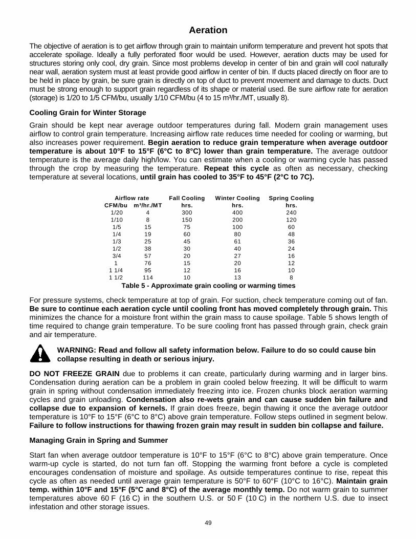
Aeration
The objective of aeration is to get airflow through grain to maintain uniform temperature and prevent hot spots that accelerate spoilage. Ideally a fully perforated floor would be used. However, aeration ducts may be used for structures storing only cool, dry grain. Since most problems develop in center of bin and grain will cool naturally near wall, aeration system must at least provide good airflow in center of bin. If ducts placed directly on floor are to be held in place by grain, be sure grain is directly on top of duct to prevent movement and damage to ducts. Duct must be strong enough to support grain regardless of its shape or material used. Be sure airflow rate for aeration (storage) is 1/20 to 1/5 CFM/bu, usually 1/10 CFM/bu (4 to 15 m³/hr./MT, usually 8).
Cooling Grain for Winter Storage
Grain should be kept near average outdoor temperatures during fall. Modern grain management uses airflow to control grain temperature. Increasing airflow rate reduces time needed for cooling or warming, but also increases power requirement. Begin aeration to reduce grain temperature when average outdoor temperature is about 10°F to 15°F (6°C to 8°C) lower than grain temperature. The average outdoor temperature is the average daily high/low. You can estimate when a cooling or warming cycle has passed through the crop by measuring the temperature. Repeat this cycle as often as necessary, checking temperature at several locations, until grain has cooled to 35°F to 45°F (2°C to 7C).
Table 5 - Approximate grain cooling or warming times
For pressure systems, check temperature at top of grain. For suction, check temperature coming out of fan. Be sure to continue each aeration cycle until cooling front has moved completely through grain. This minimizes the chance for a moisture front within the grain mass to cause spoilage. Table 5 shows length of time required to change grain temperature. To be sure cooling front has passed through grain, check grain and air temperature.
WARNING: Read and follow all safety information below. Failure to do so could cause bin collapse resulting in death or serious injury.
DO NOT FREEZE GRAIN due to problems it can create, particularly during warming and in larger bins. Condensation during aeration can be a problem in grain cooled below freezing. It will be difficult to warm grain in spring without condensation immediately freezing into ice. Frozen chunks block aeration warming cycles and grain unloading. Condensation also re-wets grain and can cause sudden bin failure and collapse due to expansion of kernels. If grain does freeze, begin thawing it once the average outdoor temperature is 10°F to 15°F (6°C to 8°C) above grain temperature. Follow steps outlined in segment below. Failure to follow instructions for thawing frozen grain may result in sudden bin collapse and failure.
Managing Grain in Spring and Summer
Start fan when average outdoor temperature is 10°F to 15°F (6°C to 8°C) above grain temperature. Once warm-up cycle is started, do not turn fan off. Stopping the warming front before a cycle is completed encourages condensation of moisture and spoilage. As outside temperatures continue to rise, repeat this cycle as often as needed until average grain temperature is 50°F to 60°F (10°C to 16°C). Maintain grain temp. within 10°F and 15°F (5°C and 8°C) of the average monthly temp. Do not warm grain to summer temperatures above 60 F (16 C) in the southern U.S. or 50 F (10 C) in the northern U.S. due to insect infestation and other storage issues.
Fall Cooling Winter Cooling Spring CoolingCFM/bu m³/hr./MT hrs. hrs. hrs.
1/20 4 300 400 240 1/10 8 150 200 120 1/5 15 75 100 60 1/4 19 60 80 48 1/3 25 45 61 36 1/2 38 30 40 24 3/4 57 20 27 16
1 76 15 20 121 1/4 95 12 16 101 1/2 114 10 13 8
Airflow rate
49

Grain Drying Grain drying removes moisture from grain by moving air through it after it has been harvested. Heat is usually added to air to speed up drying time. Grain in fields dries naturally as crops mature, giving up moisture until grain is in equilibrium with moisture in the air. Conditions become less favorable for grain to dry to safe storage levels as harvest is delayed late into fall. NOTE: Not all bins are designed for drying. See Bin Description section of Bin Operation Manual. The basics of drying can be summarized as:
Air removes water from grain.
The more airflow, the faster the drying.
The warmer the air, the more water can be removed, thus the faster the drying.
For every 20F (11C) heat rise, relative humidity (RH) is cut by about half.
The warmer the air, the drier the grain.
Airflow rate, air temperature and relative humidity influence drying speed. Air can hold more moisture when it is warm than when it is cool. The amount of moisture in the air as opposed to the amount it could hold if it were fully saturated is referred to as “Relative Humidity”. As a rule of thumb, heating air 20oF (11oC), reduces relative humidity by one-half. Table 6 illustrates how heating air decreases drying time and is expressed by the “Drying Ratio” column. Example: A 2.6 drying ratio means grain will dry 2.6 times faster than the conditions with a drying ratio of 1.
Table 6 - Drying basics Unfortunately, drying grain to 8% or 5% moisture content is very costly and also results in excessive grain damage. By incorporating a stirring machine to mix dry grain at bottom of bin with upper wet grain, desirable average moisture may be obtained. University tests found that a properly stirred bin will have less than 1% variation of moisture content from top to bottom. Drying Advantages
Preserves quality of harvested grain by reducing its exposure to weather.
Reduces grain quality losses due to head shattering and cracked kernels.
Reduces dependency on weather conditions for harvest.
Allows use of straight combining for small grains.
Reduces size and/or number of combines and other harvest-related equipment and labor required due to extended harvest time.
Allows more time for post-harvest fieldwork.
Outside Air Heated Air To RH Dries Grain To Drying Ratio
8%70°F (21°C)
60% RH70°F (21°C)
60% RH17% 5%
31%
70°F (21°C) 60% RH
4.3
2.6
For Every 20°F (11°C) Heat Rise, Relative Humidity Is Cut by 1/2
90°F
110°F
No Heat 60% 13% 1.0
50

Influence of Drying Conditions
Drying air carries moisture away from grain. Higher airflow rates give higher drying rates. Fan speed, motor size and resistance of grain to air determine airflow. Deeper grain depths and higher airflow rates cause higher static pressure against fan. Higher static pressure decreases fan output. Short, wide bins allow grain to dry better than tall, thin bins since there is less grain restriction (static pressure). Tall, thin bins may require 30 times more horsepower than short, wide bins to maintain same airflow. See Fig. 4. As air enters grain it picks up moisture, which cools the air slightly. As air moves through a deep grain mass, air temperature is gradually lowered and relative humidity is increased until air approaches equilibrium with grain. If air reaches equilibrium with grain, it passes through remaining grain without any additional drying. If high relative humidity air enters dry grain mass, moisture is removed from air and enters the grain. This slightly dried air will begin to pick up moisture when it reaches wetter grain.
Overdrying
Overdrying grain will cost the producer money in two ways: (1) An excessive amount of energy is used to dry the grain. (2) The crop is worth less because of shrinkage. See Table 7. Using a stirring machine is an excellent way to eliminate over-drying and is essential when a heater is used with a drying bin.
Table 7 - Over-drying costs when marketing corn below 15% (1€ = $1.30). Cost based on $.06 KW/hr. (.046 Euro/kW/hr.) and $1.00/Gal LP (.266 Euro/Litre of LP)
Grain Cooling
Grain dried with a heater must be cooled. Grain can be rapidly cooled immediately after it is dried, or cooling can be delayed to reduce fuel cost, increase dryer capacity, and reduce stress cracks. The cooling method can affect the type, operation and management of dryer system. Cooling effectiveness increases as drying air temperature increases. Cooling is required when a heater is used. Consider these cooling methods when selecting a drying system. - With In-bin Cooling, stop heated drying about 1% above desired final moisture content and run fan(s). Make sure grain is completely cooled before turning off fan(s). For pressure fan systems, check grain temperature at top of bin to ensure cooling front has passed completely through grain. After grain is cooled, it is usually stored in the bin. Check moisture of grain when cooling is complete to ensure grain is at desired moisture content.
Dollars Euros Dollars Euros Dollars Euros14% $0.035 € 0.031 $0.044 € 0.040 $0.079 € 0.07113% $0.061 € 0.055 $0.072 € 0.065 $0.133 € 0.12012% $0.087 € 0.078 $0.099 € 0.089 $0.186 € 0.16711% $0.117 € 0.105 $0.126 € 0.113 $0.243 € 0.219
Moisture Content
Extra Drying Costs Total Overdrying Extra Shrinkage Costs
Fig. 4
51

- Dryeration is recommended with a high-temperature dryer. The first points of moisture are easily removed from outer portion of kernel with heat. However, moisture is left in the center. By transferring hot grain to a separate dryeration bin and delaying cooling for 12 hours while steeping and tempering occur, remaining moisture will migrate to outside of kernel. Aeration fans will easily remove the last and most difficult couple points of moisture just by moving cool air (1/2 CFM/bu) through grain. Fans, perforated floors and additional handling equipment are needed for dryeration. This is the most economical way of cooling hot grain.
- Combination High Temp/Low Temp is for crops that are harvested too wet for safe low-temperature bin drying. Wet corn is partially dried with high temperatures down to about 22% or less, often with a continuous-flow dryer. Partially dried grain is moved to a low-temperature drying bin where it is slowly dried with low temperatures.
Fans
Axial fans are the most common types of fans used for aeration. They require a relatively low initial investment and operate well at static pressures below 3 to 4 inches (76 to 100mm) or (750 pa) water gauge. Centrifugal fans deliver a fairly consistent airflow over a wide range of static pressure, but require a higher initial investment than axial fans. Centrifugal fans are much quieter and more efficient. When aeration is required for tall bins or small grains that create high static pressures, 3,500-rpm centrifugal fans are recommended.
Table 8 - Fan airflow comparisons (CFM)
Table 9 - Fan airflow comparisons (m³/hr.)
Contact your Sukup dealer for help in selecting fan(s) that will work best.
Airflow Requirements
Table 10 - Airflow requirements CFM/bu (m³/hr./MT)
- 1/20 to 1/5 CFM/bu (Usually 1/10) 4 to 15 m³/hr./MT (Usually 8)- 1/2 CFM/bu* 38 m³/hr./MT*
Cooling in Bin: - 1/2 to 1 CFM/bu (Usually 1/2) 38 to 76 m³/hr./MT- 1/4 t o 1/2 CFM/bu 19 to 38 m³/hr./MT
Drying: Natural Air - 1 to 3 CFM/bu 76 to 228 m³/hr./MTLow Temp - 1 to 3 CFM/bu 76 to 228 m³/hr./MTHigh Temp - 1-1/2 to 5 CFM/bu 114 to 380 m³/hr./MT
Roof Dryer - 12 to 22 CFM/bu 911 to 1670 m³/hr./MT*Airflow based on dryer capacity should be calculated as follows: 12 CFM per bu/hr. (815 m³/hr. per MT/hr.)
Wet Holding Tank:
Cooling Grain, Hot from Dryer:Aeration (storage):
F a n T yp e H P R P M 0 2 4 6 8A x ia l 5 -7 3 5 0 0 1 2 ,8 0 0 1 0 ,3 0 0 6 ,2 5 0 - -C e n tr ifu g a l 7 .5 1 7 5 0 1 2 ,0 0 0 1 0 ,4 0 0 8 ,5 0 0 6 ,7 0 0 -H ig h -S p e e d C e n tr ifu g a l 7 .5 3 5 0 0 5 ,0 0 5 4 ,6 0 0 4 ,2 5 0 3 ,8 5 0 3 ,4 0 0In -L in e C e n tr ifu g a l 5 -7 3 5 0 0 6 ,3 7 0 5 ,8 1 5 5 ,1 5 0 4 ,7 1 5 3 ,9 3 5
S ta tic P re s s u re (In c h e s )
F a n T yp e H P k W R P M 0 5 0 1 0 1 1 5 2 2 0 3A x ia l 7 .0 5 .2 2 9 0 0 2 1 ,5 0 0 1 5 ,3 0 0 4 ,7 5 0 - -C e n tr ifu g a l 7 .5 5 .5 1 4 5 0 2 2 ,5 0 0 1 9 ,0 0 0 1 4 ,6 0 0 - -H ig h -S p e e d C e n tr ifu g a l 7 .5 5 .5 2 9 0 0 1 0 ,4 0 0 9 ,2 0 0 8 ,0 0 0 7 ,0 0 0 5 ,7 0 0
S ta tic P re ss u re (m m )
Fig. 5
52
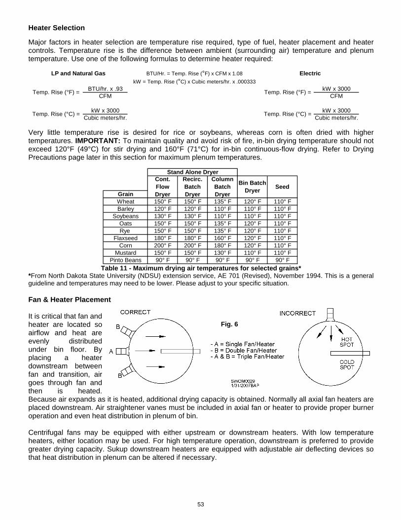
Fig. 6
Heater Selection
Major factors in heater selection are temperature rise required, type of fuel, heater placement and heater controls. Temperature rise is the difference between ambient (surrounding air) temperature and plenum temperature. Use one of the following formulas to determine heater required:
Very little temperature rise is desired for rice or soybeans, whereas corn is often dried with higher temperatures. IMPORTANT: To maintain quality and avoid risk of fire, in-bin drying temperature should not exceed 120°F (49°C) for stir drying and 160°F (71°C) for in-bin continuous-flow drying. Refer to Drying Precautions page later in this section for maximum plenum temperatures.
Table 11 - Maximum drying air temperatures for selected grains* *From North Dakota State University (NDSU) extension service, AE 701 (Revised), November 1994. This is a general guideline and temperatures may need to be lower. Please adjust to your specific situation. Fan & Heater Placement It is critical that fan and heater are located so airflow and heat are evenly distributed under bin floor. By placing a heater downstream between fan and transition, air goes through fan and then is heated. Because air expands as it is heated, additional drying capacity is obtained. Normally all axial fan heaters are placed downstream. Air straightener vanes must be included in axial fan or heater to provide proper burner operation and even heat distribution in plenum of bin. Centrifugal fans may be equipped with either upstream or downstream heaters. With low temperature heaters, either location may be used. For high temperature operation, downstream is preferred to provide greater drying capacity. Sukup downstream heaters are equipped with adjustable air deflecting devices so that heat distribution in plenum can be altered if necessary.
BTU/Hr. = Temp. Rise (°F) x CFM x 1.08
kW = Temp. Rise (°C) x Cubic meters/hr. x .000333BTU/hr. x .93 kW x 3000
CFM CFM
kW x 3000 kW x 3000Cubic meters/hr. Cubic meters/hr.
LP and Natural Gas Electric
Temp. Rise (°F) =
Temp. Rise (°C) =
Temp. Rise (°F) =
Temp. Rise (°C) =
GrainWheat 150° F 150° F 135° F 120° F 110° FBarley 120° F 120° F 110° F 110° F 110° F
Soybeans 130° F 130° F 110° F 110° F 110° FOats 150° F 150° F 135° F 120° F 110° FRye 150° F 150° F 135° F 120° F 110° F
Flaxseed 180° F 180° F 160° F 120° F 110° FCorn 200° F 200° F 180° F 120° F 110° F
Mustard 150° F 150° F 130° F 110° F 110° FPinto Beans 90° F 90° F 90° F 90° F 90° F
Stand Alone DryerCont. Flow Dryer
Recirc. Batch Dryer
Column Batch Dryer
Bin Batch Dryer
Seed
53

Heater Controls Heater efficiency and cost of operation can be improved through proper selection of controls. For continuous flow drying, use high-low or modulating valve control. When two or more fans are used on a bin, use a high-low or thermostat control, which can be controlled through a dual burner control. Following are types of controls that are commonly available.
Thermostat - This unit cycles heater completely on and off to maintain plenum temperature. It is the least expensive control, but also least efficient. When burner is shut off, fan is blowing outside air into plenum, cooling it off. On-and-off action provides an average temperature corresponding to the setting, but with short periods of high and low temperatures when thermostat cycles burner on or off. High-Low Burner - The high-low burner control cycles burner from a high setting to a 20°F to 30°F (10°C to 15°C) lower setting to maintain a more uniform plenum temperature. This eliminates extremes in plenum temperatures from a standard thermostat and provides economy of operation. NOTE: Use High-Low Control with a dual burner control when more than one fan and heater is used on bin. Modulating Valve - The modulating valve provides the most precise temperature control by continuously regulating burner flame to maintain a constant temperature. Modulating valve works through a capillary tube filled with gas that expands and contracts with changes in plenum temperature. This gas moves a diaphragm controlling LP gas or natural gas pressure to burner. Humidistat - The humidistat is used with a low-temperature burner and is located in plenum of bin. This cycles burner on and off based on relative humidity to control humidity of drying air.
Type of Fuel
Use of either propane or natural gas is based on availability. Burners for both fuels can be sized to provide heat required. When using propane as a fuel, either liquid or vapor may be used. Generally, a heater must include a vaporizer for liquid propane when ambient temperature is below 32°F (0°C) and one million BTU/hr. (292 kW) is required. See Sukup heater manual for size of propane tanks required when using vapor propane.
When using natural gas, contact your gas company to determine if adequate line pressure is available for operation. Getting sufficient natural gas supply can be a problem from some suppliers. For high temperature heaters, you will need to get 15psi (100Kpa) supply pressure while operating to get max BTU/hr. (kW/hr.) capacity from heater. If natural gas company can’t supply this, you will need to buy a heater with larger piping, e.g., 1-1/4” (31.75 mm). Electric heaters provide 1°F to 4°F (1°C to 2°C) of temperature rise. LP and natural gas burners usually have lower operating costs than electrical heaters.
54

Drying Guidelines to Prevent Spoilage along Bin Wall A large amount of moisture is removed during drying. Approximately 1 gallon of water (3.785 Liters) can be removed from one bushel (.029 Metric Ton) of corn at 25% moisture.
Completely empty bin before filling with final batch of grain. Dry grain at no more than 100F (38°C) on final batch. In cooling process (after grain is dried), run fan with heater for 1 day at 50F (10°C) to cool grain (run until air does not steam eye glasses when checked), then run fans with no heat for two days before shutting down system. Run fans and stirring machines (no heat) for 24 hours each month while grain is in storage and only on days in which humidity is 50% or less.
Follow these guidelines to prevent grain spoilage caused by moisture condensation during drying. This problem is most severe when drying at higher temperatures in colder climates.
- Use bin floors with perforated flashing to ensure maximum airflow along bin wall. - Fans should provide a minimum of 1.75 CFM/bu (117 m³/hr./MT) aeration rate when bin is full. Listed below are minimum fan recommendations based on 16' (5M) grain depth and 1.75 CFM/bu (117 m³/hr./MT) aeration rate.
Bin Dia. Type of Cent. Fan Qty. of Fans Type of Axial Fan Qty. of Fans24' 10HP 1 28" 10-15 HP 1 27' 15HP 1 28" 10-15 HP 1 30' 20HP 1 28" 10-15 HP 2 33' 10HP 2 28" 10-15 HP 2 36' 10HP 2 28" 10-15 HP 2 42' 15HP 2 28" 10-15 HP 2
48' 20HP 2 28" 10-15 HP 3
- Stirring machines eliminate over-dried grain, increase airflow, and preserve grain quality. Stirring mixes driest grain at bottom of bin with wetter grain toward the top. This results in more uniform moisture content. University tests have shown less than 1% moisture variation from top to bottom in stirred grain.
- Airway tubes (used in drying process) are perforated, triangular tubes that attach along inside of bin sidewall. The main purpose of airway tubes is to remove moisture condensation and reduce spoilage costs. Drying of hot grain in bin can cause sidewall condensation. For every 10 points of moisture removed from one bushel of corn, one gallon of water is produced. Some of this water condenses on bin wall, causing spoiled grain. Airway tubes work to remove water from walls. Make certain they are not plugged with fines or bees wings. Make sure flashing is punched so tubes extend through flashing to allow maximum airflow.
Fig. 7
55

Drying Precautions
WARNING: Read and follow all safety information below. Failure to do so could cause bin fire resulting in death or serious injury.
Table 12 – Maximum plenum temp. for corn to avoid an in-bin fire and maintain grain quality
*Temperatures are only general recommendations. Drying temperatures for other grains vary due to ambient temperature, moisture content, and rate of drying. Temperatures may need to be lower due to special circumstances, such as drying seed corn. Consult your local extension office for further information on specific plenum temperatures when drying other grains.
Precautionary Steps to Help Prevent an In-Bin Fire
- Maximum plenum temperature for drying without stirring should be no more than 10°F (5°C) above ambient (outside) air. This will help prevent a fire as well as maintain grain quality.
- DO NOT combine drying equipment from various companies. Sukup-designed heaters are intended to be used with Sukup-designed fans only. Heaters have a variety of automatic controls to shut them down in case of ignition failure, high temperature limits or airflow failure. Combining equipment from various companies may cause a lack of safety controls needed to cut power. Check these items regularly for proper operation to reduce chance of fire.
- Keep area beneath perforated floor clean of all fines and foreign material as they may cause a bin fire. For even heat distribution, floor supports should not block transition.
- Grain should be screened before going into bin to avoid formation of fines and trash. Use of a grain spreader will help distribute fines.
- Thoroughly ventilating bins with dryer fan before igniting heater will reduce risk of a fire or explosion from leaking fuel.
- Faulty electrical wiring can also cause fires. Be certain components are wired by a qualified electrician.
If a fire is suspected, follow these basic fire safety procedures to ensure safety for you, your family and employees:
- Always account for all co-workers, neighboring farmers and first responders.
- Shut off gas at heater and supply tank. Shut off fan. Call fire department.
- Keep fire away from fuel supply tanks and keep them cool by spraying water on them if needed.
- Seal fan inlet and any other openings to smother fire.
- Remove fan and heater from transition. Sandbag transition opening. If possible, flood bottom of bin (plenum) with water to a depth of 4” (100 mm) above perforated floor. This will protect steel floor supports and may extinguish fire, depending upon its location.
- If fire is located higher in bin, a long pipe with small holes may be inserted through bin wall or manhole and into grain to direct water at source of fire. This may help keep fire in a centralized location, but it’s nearly impossible to extinguish a fire in a grain bin by simply pouring water on it. These fires can only be extinguished by completely emptying bin.
- Take note of bin surroundings to avoid heat transfer onto neighboring structures. Pay special attention to propane tanks. Cool if necessary.
- ALL GRAIN MUST BE REMOVED FROM BIN TO REACH POINT OF FIRE. Do not cut holes in bin to remove grain. Do not enter a bin that is on fire. Grain may bury you.
- Grain may smolder for days. Do not restart fan in hope that fire has gone out unless all grain has been removed from bin.
In-Bin Drying - without a Stirring MachineIn-Bin Drying - with Stirring Machine 120°F 50°C
In-Bin Continuous Flow Drying 160°F 70°CPortable Dryer 200°F 93°C
Maximum Plenum Temperature for Corn*10°F (5°C) above ambient (outside) air
56

NOTE: Grain management information contained in this manual provides general guidelines and comes from sources listed below. Your specific situation may require additional procedures or attention. Seek advice from your local extension office or consulting engineer for your specific operation.
SOURCES: MWPS-13 Grain Drying, Handling and Storage Handbook. AED-20 Managing Dry Grain in Storage ASAE Standard S412.3 Feb ’03, St. Joseph, Mich. University Extension Offices
- Iowa State University - North Dakota State University - Purdue University - University of Kentucky - University of Missouri
Additional grain drying and storage information is available from your local extension service and from Midwest Plan Service, 4306D Elings Hall, Iowa State University, Ames, Iowa 50011.
Sukup Manufacturing Co. 1555 255th Street, Box 677
Sheffield, Iowa, USA 50475-0677 Phone: 641-892-4222 Fax: 641-892-4629
Website: www.sukup.com Email: [email protected]
57

OBSERVATION Musty or spoiled grain odor Hard layer or core of grain. Warm grain below top surface. Surface grain wet or slimy. Grain is sticking or frozen together. Hard surface crust, caked and blocking airflow; possibly strong enough to support a person. Condensation under roof. Wet or spoiled grain directly under fill cap or on surface outside of bin center. No airflow through grain with aeration fan running. White dust visible whenever grain is stirred. Cooling time required much longer than usual Exhaust air temperature in center of bin warmer than on outside. Unknown grain conditions in bin center.
Troubleshooting
PROBABLE CAUSE Moisture accumulation in spot(s). High moisture or spoiled, caked grain mass. Compacted mass blocking airflow. Moisture content too high. Early signs of moisture migration. Severe moisture migration and condensation in top surface. Warm grain in cold weather; severe convection circulation and moisture migration. Leaky roof cap, gravity spout, bolt hole, or fixture that funnels condensation flow. Moldy caked grain mass blocking airflow. Possible moldy grain layer above aeration duct or floor. Mold on grain but not sufficient spoilage to seal top surface. Increased fines in grain resulting in reduction of airflow: Fines can cause airflow resistance to increase 2-4 times as much as clean grain.
Fine material accumulation in bin center reducing airflow; airflow through center reduced compared to clean grain around outside. Too deep to probe; bin too full to access; no temperature sensing cables installed.
RECOMMENDED ACTION
Run fan to cool any hot spots. If damage to grain is severe, remove grain. Run aeration or drying fans. Cool and dry if airflow is adequate, otherwise unload to remove all spoiled grain. Run fan until exhaust air temperature equals desired grain temperature. Run aeration fan. Cool grain until exhaust temperatures equal desired grain temperatures. Remove spoiled layer. Wear dust mask to filter mold spores. Run fan to cool grain if needed after spoilage removed. Aerate until exhaust air temperature equals outdoor air temperature at beginning of aeration cycle. Check fill cap seal, gravity spout, and caulking around roof inlets and joints. Also check grain heat and under roof surface at night for water accumulation.
Determine location and scope of spoilage. Remove spoiled grain and market or re-bin good grain. Wear dust mask working in grain. Evaluate grain condition throughout bin where possible. Keep in mind grain has deteriorated to some degree. Run fan until grain and exhaust air temp readings indicate grain is at required temperature, regardless of fan time.
Run fan long enough to cool the center, irrespective of outside grain temp. Draw down bin center to remove fines and decrease grain depth for easier air passage. Withdraw some grain from bin to observe grain. Do not overfill bin.
58

Maintenance
Grain bin and equipment maintenance before and during harvest season will help ensure that good quality grain will be stored and preserved. Bin will provide many years of extended service if properly maintained. Information below outlines maintenance inspections that should be performed on a regular basis. Use it as a maintenance checklist.
WARNING: Damage from lack of maintenance may cause sudden structural failure and collapse, which may result in death or serious injury. Frequently monitor
and inspect bin and foundation for any deflections, cracks or deviations that may occur. Follow operation and maintenance instructions described in this manual.
Roof, Stairs & Vents
IMPORTANT: Clean debris off of bin roof, peak ring, roof vents, and stairs at end of each harvest season. Dust and debris can cause damage to roof as well as make steps/rungs slippery and unsafe to walk on. Not cleaning debris above roof vents can cause white and brown rust to develop on galvanized metal.
If an excessive amount of heavy snow accumulates or builds up unevenly on one side of roof, it must be removed immediately.
IMPORTANT: Inspect bin roof and sidewall for leaks, loose or sheared bolts, and rust or other corrosion. Caulk any cracks, replace and tighten all missing bolts and nuts, and remove rust or corrosion with wire brush and paint over tainted area. If problem is severe, contact Sukup Manufacturing Co. customer service and your dealer.
Ensure proper function of attachments to all bin openings such as manhole and center caps. Be sure all latches and hold-down clips are used as intended. Also, make certain cap has tight weather seal and is in correct position if overhead conveyor is mounted. Spouts require roof cap to be permanently fixed.
Tighten any loose bolts used to attach roof steps to roof ribs and, if necessary, install handrails to increase worker safety and prevent accidents. Also, be certain roof ring expanders and splices are in their correct position and properly tightened. Because of workers being at extensive heights, it is important that all roof components be rigid.
Whenever on roof, inspect all roof panels, supporting ribs, stairs, steps, vents, and especially all connections to be certain accidents do not occur. Roof vents should be checked for blockage caused by dirt, dust, debris, frost, ice, bird nests, etc. Clean any debris to allow free airflow and prevent damage to roof.
Ladders, Catwalks & Supports
Be certain that access ladders, catwalks and platforms are complete and securely fastened to bin. Cages should be on ladders longer than 20’. Cages must begin no more than 7’ from bottom of ladder. If ladders exceed height of 30’, a landing platform must be provided at each 30’ offset. Ladders should be no more than 7” from bin wall.
59

Catwalks are often supported by steel structures and sometimes are bolted to bin stiffener with slip joints. Check all connections between catwalks and supports often. Bent braces, loose bolts and sidewall damage are all extreme situations that could put someone’s safety in serious danger.
While climbing ladder, check for any worn-out or loose rungs, loose or missing bolts, and dangerous jagged edges protruding from ladder or safety cage. Determine cause and fix or replace. If sheared bolt is discovered, contact Sukup Manufacturing Co. customer service and an independent consulting engineer. It may be an indication of a more serious problem.
Sidewall Sheets, Stiffeners & Doors
Inspect exterior of bin on a regular basis. Check for missing bolts, buckled or torn sheets, sidewall bulges or any unusual changes in bin’s appearance. Pay particular attention to bolted joints, noting any waviness along edges, elongated bolt holes, or cracks, all of which are signs of over-stress. If a serious structural problem is detected, contact Sukup Manufacturing Co. customer service and an independent consulting engineer.
Shim all stiffener base plates if void appears between base plate and concrete. Also, ensure each stiffener base is correctly anchored to foundation. If base plate is not bearing uniformly on concrete foundation, it may cause stiffener buckling somewhere above base.
Visually inspect stiffeners and splices to ensure there are no gaps. Improperly connected stiffeners will cause sidewall and stiffener buckling. Be certain base is level on concrete, all bolts and nuts are tight, and stiffeners are supported through aeration tunnel if one is present.
Be certain door is correctly installed and caulked. Check corrugation around door to ensure a watertight
seal. Before filling bin, remember to lock inner doors tight against frame to ensure no structural damage occurs.
Foundations & Tunnels
Inspect bins and foundations for structural problems. An uneven foundation settlement can cause gaps at bottom of bin, resulting in spilled grain, entry points for water, insects, rodents, and allow forced air to escape, reducing efficiency and increasing costs.
Inspect concrete routinely for exposed rebar, unusual cracking, or spalling of concrete.
Be sure all anchor bolts are tighten and undamaged. Cracks that develop around anchor bolts result in bin being susceptible to wind damage. Be certain base of bin is uniformly resting on foundation and sealant is intact. If gaps occur, caulk between bottom of bin and foundation.
Sidewall and tunnel failure may occur if tunnel is not correctly constructed or supported at tunnel outlet on stemwall. If cracks or breaks occur in stemwall, contact consulting engineer immediately for proper instructions and measures to correct damage.
Inspect tunnel roofs on a regular basis for cement spalling, cracks and deflections. Inform concrete contractor of any significant appearance of cracks or impending failure of tunnel roofs. Removable conveyor cover plates must be fitted, flashed and sealed to prevent accidental leakage into conveyors, which could result in eccentric discharge of grain from bin.
Aeration Systems
Periodically remove fan transition and check beneath floor for condition of supports, presence of pests, dust buildup and foreign material. Clean and repair if required.
Check fans, heaters, transitions and ducts for corrosion. Remove any accumulated dust and dirt that will reduce operating efficiency. Be sure all wire and pipe connections are tight and in place.
60

Inspect aeration system by looking for grain leaks and grain remaining in trenches. Find the source and remove any grain in the way. Caulk any holes or cracks to prevent insects or water from getting in and grain from getting out.
Grease motor bearings (if required) at least twice annually and be sure fan blades are spinning freely. Fans should not be turned on until a substantial amount of grain covers aeration or drying floors.
Electrical
Wiring for fans and other electrical components should be inspected for corrosion and cracked, frayed, or broken insulation. Exposed wiring should be run through waterproof, dust-tight conduit. Avoid kinks in conduit and make sure all connections are secure.
Check control boxes for rodent damage. If found, clean and repair or replace broken wiring, relays and other components, and seal over opening that allowed rodent entry.
Site Maintenance
Remove any spilled grain from bin site. Mow around bins to reduce likelihood of insect or rodent infestation and make certain water drains away from bin foundation. Items or debris left near bin site may interfere with safe, unobstructed movement around bin.
Treat outside of bin at foundation and around door, ducts, and fans with insecticide if an insect problem arises.
Thoroughly clean all bins by removing all old grain. Do not put new grain on top of old. This will help prevent mold and insect infestation of new grain. Remove all traces of old grain from combines, truck beds, grain carts, augers, or any other equipment used for harvesting.
Remove all rust and cover with rust-inhibiting primer or paint. It’s better to take care of problems in early stages of corrosion than have rust streaks running down bin.
NOTE: If you find buckled sheets, sidewall bulges or any unusual changes in bin’s appearance, please contact Sukup Manufacturing Co. customer service if bin is still under warranty, or an independent consulting engineer to determine problem and find a solution.
Replacement Parts
Grain bins affect many farming operations. Modifications and repairs are often needed due to weather, deterioration, usage and mishaps. The key to keeping your bin in first-rate condition is to frequently review maintenance checklist on these pages and repair any problems promptly. To replace any deteriorated parts such as bin sheets and flooring, contact your local dealer/distributor. NOTE: Do not substitute materials for replacement parts. Your bin is assembled with certain materials at specific thicknesses. Do not replace parts without consulting your dealer.
Prior to equipment use, please check that all decals are in place according to this manual and in good legible condition. Safety decals are available for replacement at no charge for Sukup equipment. Refer to Safety Section of this manual. Please specify decal number when requesting replacements.
61


Additional copies of manual can be requested at address, phone number or e-mail address shown below. Please indicate manual number L13920 when requesting Bin Operation Manual.
Sukup Dealer Information
Dealer name:___________________________
Address: ______________________________
Cell phone: ____________________________
Office phone:___________________________
Fax:___________________________________
In Case of Emergency
Have emergency numbers and written directions to your location near a phone, and arrange and practice a safety plan. Floor plans or workplace maps that clearly show emergency escape routes should be in the safety plan. Color coding will aid employees in determining their routes and assignments.
Sukup Manufacturing Co. 1555 255th Street, Box 677
Sheffield, Iowa, USA 50475-0677 Phone: 641-892-4222 Fax: 641-892-4629
Website: www.sukup.com Email: [email protected]
Ambulance • Fire • Police: 9-1-1
Bin rescue team:_________________________
Local EMS team:_________________________
Address of work site: _____________________
Directions to work site:____________________