commercial-scale demonstration of the … library/research/coal/major...fresh oil was introduced...
TRANSCRIPT

TPR12C.DOC Apr. - Jun. 97 Page 1 of 46 06/09/98
COMMERCIAL-SCALE DEMONSTRATION OF THELIQUID PHASE METHANOL (LPMEOH) PROCESS
TECHNICAL PROGRESS REPORT NO. 12
For The Period
1 April - 30 June 1997
Prepared by
Air Products and Chemicals, Inc.Allentown, Pennsylvania
and
Eastman Chemical CompanyKingsport, Tennessee
for theAir Products Liquid Phase Conversion Company, L.P.
Prepared for the United States Department of EnergyFederal Energy Technology Center
Under Cooperative Agreement No. DE-FC22-92PC90543
Patents cleared by Chicago on 02 September 1997.

TPR12C.DOC Apr. - Jun. 97 Page 2 of 46 06/09/98
DISCLAIMER
This report was prepared by Air Products & Chemicals, Inc. and Eastman Chemical Company for the AirProducts Liquid Phase Conversion Company, L.P., pursuant to a Cooperative Agreement partially funded bythe U.S. Department of Energy, and neither Air Products & Chemicals, Inc., Eastman Chemical Company, theAir Products Liquid Phase Conversion Company, L.P., nor any of their subcontractors nor the U.S.Department of Energy, nor any person acting on behalf of either:
(A) Makes any warranty or representation, express or implied, with respect to the accuracy, completeness, orusefulness of the information contained in this report, or that the use of any information, apparatus, method, orprocess disclosed in this report may not infringe privately owned rights; or(B) Assumes any liabilities with respect to the use of, or for damages resulting from the use of, anyinformation, apparatus, method, or process disclosed in this report.
Reference herein to any specific commercial product, process, or service by trade name, trademark,manufacturer, or otherwise, does not necessarily constitute its endorsement, recommendation, or favoring bythe U.S. Department of Energy. The views and opinions of authors expressed herein does not necessarily stateor reflect those of the U.S. Department of Energy.

TPR12C.DOC Apr. - Jun. 97 Page 3 of 46 06/09/98
Abstract
The Liquid Phase Methanol (LPMEOH) Demonstration Project at Kingsport, Tennessee, isa $213.7 million cooperative agreement between the U.S. Department of Energy (DOE) andAir Products Liquid Phase Conversion Company, L.P. (the Partnership). Air Products andChemicals, Inc. (Air Products) and Eastman Chemical Company (Eastman) formed thePartnership to execute the Demonstration Project. The LPMEOH Process DemonstrationUnit was built at a site located at the Eastman complex in Kingsport.
During this quarter, comments from the DOE on the Topical Report “Economic Analysis -LPMEOH™ Process as an Add-on to IGCC for Coproduction” were received. Arecommendation to continue with design verification testing for the coproduction of dimethylether (DME) and methanol was made. DME design verification testing studies show theliquid phase DME (LPDME) process will have a significant economic advantage for thecoproduction of DME for local markets. An LPDME catalyst system with reasonable long-term activity and stability is being developed. A recommendation document summarizingcatalyst targets, experimental results, and the corresponding economics for a commerciallysuccessful LPDME catalyst was issued on 30 June 1997.
The off-site, product-use test plan was updated in June of 1997. During this quarter, AcurexEnvironmental Corporation and Air Products screened proposals for this task by thelikelihood of the projects to proceed and the timing for the initial methanol requirement.Eight sites from the list have met these criteria. The formal submission of the eight projectsfor review and concurrence by the DOE will be made during the next reporting period.
The site paving and final painting were completed in May of 1997. Start-up activities werecompleted during the reporting period, and the initial methanol production from thedemonstration unit occurred on 02 April 1997. The first extended stable operation at thenameplate capacity of 80,000 gallons per day (260 tons per day) took place on 06 April1997.
Pressure drop and resistance coefficient across the gas sparger at the bottom of the reactorincreased over this initial operating period. The demonstration unit was shut down from08 May - 17 June 1997 as part of a scheduled complex outage for the Kingsport site. Duringthis outage, the gas sparger was removed, cleaned, and reinstalled. After completion of othermaintenance activities, the demonstration unit was restarted, and maintained stable operationthrough the remainder of the reporting period. Again, the gas sparger showed an increase inpressure drop and resistance since the restart, although not as rapidly as during the April-Mayoperation. Fresh oil was introduced online for the first time to a new flush connection on thegas inlet line to the reactor; the flush lowered the pressure drop by 1 psi. However, theeffects were temporary, and the sparger resistance coefficient continued to increase.Additional flushing with both fresh oil and entrained slurry recovered in the cyclone andsecondary oil knock-out drum will be attempted in order to stabilize the sparger resistancecoefficient.

TPR12C.DOC Apr. - Jun. 97 Page 4 of 46 06/09/98
Catalyst activity, as defined by the ratio of the rate constant at any point in time to the rateconstant for a freshly reduced catalyst (as determined in the laboratory autoclave), declinedmore rapidly than expected. A catalyst slurry sample was taken during the May/June 1997complex outage for analysis.
Overall, the LPMEOH™ Demonstration Unit operated well during the initial campaign. Theavailability of the LPMEOH™ Demonstration Unit was 94.9% during the reporting period.All methanol produced (a total of 2,900,692 gallons) was used by Eastman in the productionof methyl acetate, and ultimately cellulose acetate and acetic acid. The start-up wassuccessfully completed in a safe and environmentally sound manner.
Ninety-eight percent (98%) of the $38 million of funds forecast for the Kingsport portion ofthe LPMEOH Process Demonstration Project for the Phase 1 and Phase 2 tasks have beenexpended (as invoiced), as of 30 June 1997. Five percent (5%) of the $158 million of fundsfor the Phase 3 tasks have been expended (as invoiced), as of 30 June 1997.

TPR12C.DOC Apr. - Jun. 97 Page 5 of 46 06/09/98
Table of Contents
Abstract..................................................................................................................................3ACRONYMS AND DEFINITIONS............................................................................................7Executive Summary ..............................................................................................................9A. Introduction .....................................................................................................................12B. Project Description...........................................................................................................12C. Process Description..........................................................................................................13D. Results and Discussion ....................................................................................................14
Task 1.2 Permitting ..................................................................................................14Task 1.3 Design Engineering....................................................................................14Task 1.4 Off-Site Testing (Definition and Design) ...................................................15Task 1.5 Planning and Administration ....................................................................16
Task 1.5.1 Product-Use Test Plan ................................................................16Task 1.5.2 Commercialization Studies .........................................................16Task 1.5.3 DME Design Verification Testing..............................................18Task 1.5.4 Administration and Reporting...................................................20
Task 2.1 Procurement ..............................................................................................21Task 2.2 Construction ..............................................................................................21Task 2.3 Training and Commissioning....................................................................21Task 2.4 Off-Site Testing (Procurement and Construction)....................................22Task 2.5 Planning and Administration ...................................................................22Task 3.1 Start-up .....................................................................................................23Task 3.2 LPMEOH™ Process Demonstration Facility Operation ..........................23
Task 3.2.1 Methanol Operation....................................................................23Task 3.2.2 DME Design, Modification and Operation .................................28
Task 3.3 On-Site Testing (Product-Use Demonstration).........................................28Task 3.4 Off-Site Testing (Product-Use Demonstration).........................................28Task 3.5 Data Analysis and Reports........................................................................29Task 3.6 Planning and Administration ...................................................................29
E. Planned Activities for the Next Quarter .........................................................................30F. Conclusion ........................................................................................................................30

TPR12C.DOC Apr. - Jun. 97 Page 6 of 46 06/09/98
Table of Contents (cont’d)
APPENDICES .......................................................................................................................32APPENDIX A - SIMPLIFIED PROCESS FLOW DIAGRAM ..................................32APPENDIX B - PROJECT EVALUATION PLAN FOR BUDGET PERIOD NO.2.................................................................................................................................33APPENDIX C - TASK 1.4 - OFF-SITE TESTING (DEFINITION AND DESIGN) .34APPENDIX D - TASK 1.5.2 - PROCESS ECONOMIC STUDY...............................35APPENDIX E - TASK 1.5.3 - DME DESIGN VERIFICATION TESTING..............36APPENDIX F - TASK 1.5.4 - APPROVAL FOR BUDGET PERIOD THREE .........37APPENDIX G - TASK 2.5 - PARTNERSHIP ANNUAL PLAN................................38APPENDIX H - TEST AUTHORIZATION K1 - METHANOL SYNTHESISWITH BASELINE CATALYST - INITIAL SHAKEDOWN AND DESIGNPRODUCTION TESTS .............................................................................................39APPENDIX I - TASK 3.2.1 - RESULTS OF DEMONSTRATION PLANTOPERATION ............................................................................................................40APPENDIX J - TASK 3.2.1 - SAMPLES OF DETAILED MATERIAL BALANCEREPORTS .................................................................................................................41APPENDIX K - TEST AUTHORIZATION K22 - METHANOL SYNTHESISWITH BGL-TYPE SYNGAS .....................................................................................42APPENDIX L - METHODS OF CALCULATION FOR KEY PROCESSPARAMETERS..........................................................................................................43APPENDIX M - TASK 3.6 - INTERIM PROJECT REVIEW MEETING.................44APPENDIX N - TASK 3.6 - MILESTONE SCHEDULE STATUS AND COSTMANAGEMENT REPORTS .....................................................................................45APPENDIX O - PRESS RELEASE (21 MAY 1997) AND PRESS COVERAGE.......46

TPR12C.DOC Apr. - Jun. 97 Page 7 of 46 06/09/98
ACRONYMS AND DEFINITIONS
Acurex - Acurex Environmental CorporationAir Products - Air Products and Chemicals, Inc.AFDU - Alternative Fuels Development Unit - The “LaPorte PDU”Balanced Gas - A syngas with a composition of hydrogen (H2), carbon monoxide (CO), and
carbon dioxide (CO2) in stoichiometric balance for the production of methanolCarbon Monoxide Gas - A syngas containing primarily carbon monoxide (CO); also called CO GasCatalyst Age (η -eta) - the ratio of the rate constant at any point in time to the rate constant for a freshly reduced
catalyst (as determined in the laboratory autoclave)Catalyst Concentration - Synonym for Slurry ConcentrationCatalyst Loading - Synonym for Slurry ConcentrationCO Conversion - the percentage of CO consumed across the reactorCrude Grade Methanol - Underflow from rectifier column (29C-20), defined as 80 wt% minimum purity;
requires further distillation in existing Eastman equipment prior to useDME - dimethyl etherDOE - United States Department of EnergyDOE-FETC - The DOE's Federal Energy Technology Center (Project Team)DOE-HQ - The DOE's Headquarters - Coal Fuels and Industrial Systems (Project Team)DTP - Demonstration Test Plan - The four-year Operating Plan for Phase 3, Task 2 OperationDVT - Design Verification TestingEastman - Eastman Chemical CompanyEIV - Environmental Information VolumeEMP - Environmental Monitoring PlanEPRI - Electric Power Research InstituteFresh Feed - sum of Balanced Gas, H2 Gas, and CO GasGas Holdup - the percentage of reactor volume up to the Gassed Slurry Height which is gasGassed Slurry Height - height of gassed slurry in the reactorHAPs - Hazardous Air PollutantsHydrogen Gas - A syngas containing an excess of hydrogen (H2) over the stoichiometric balance for
the production of methanol; also called H2 GasIGCC - Integrated Gasification Combined Cycle, a type of electric power generation plantIGCC/OTM - An IGCC plant with a "Once-Thru Methanol" plant (the LPMEOH Process) added-onInlet Superficial Velocity - the ratio of the actual cubic feet of gas at the reactor inlet (calculated at the reactor
temperature and pressure) to the reactor cross-sectional area (excluding the areacontribution
by the internal heat exchanger); typical units are feet per secondK - Sparger resistance coefficient (term used in calculation of pressure drop)KSCFH - Thousand Standard Cubic Feet per HourLaPorte PDU - The DOE-owned experimental unit (PDU) located adjacent to Air Products’ industrial
gas facility at LaPorte, Texas, where the LPMEOH process was successfully pilotedLPDME - Liquid Phase DME process, for the production of DME as a mixed coproduct with
methanolLPMEOH - Liquid Phase Methanol (the technology to be demonstrated)MeOH - methanolMethanol Productivity - the gram-moles of methanol produced per hour per kilogram catalyst (on an oxide basis)MTBE - methyl tertiary butyl etherMW - molecular weight, pound per pound moleNEPA - National Environmental Policy ActOSHA - Occupational Safety and Health Administrationρ - density, pounds per cubic foot∆P - pressure drop, psiPartnership - Air Products Liquid Phase Conversion Company, L.P.

TPR12C.DOC Apr. - Jun. 97 Page 8 of 46 06/09/98
PDU - Process Development UnitACRONYMS AND DEFINITIONS (cont’d)
PFD - Process Flow Diagram(s)ppbv - parts per billion (volume basis)Project - Production of Methanol/DME Using the LPMEOH Process at an
Integrated Coal Gasification Facilitypsi - Pounds per Square Inchpsia - Pounds per Square Inch (Absolute)psig - Pounds per Square Inch (gauge)P&ID - Piping and Instrumentation Diagram(s)Raw Methanol - sum of Refined Grade Methanol and Crude Grade Methanol; represents total methanol
which is produced after stabilizationReactor Feed - sun of Fresh Feed and Recycle GasReactor O-T-M Conversion - percentage of energy (on a lower heating value basis) in the Reactor Feed converted to
methanol (Once-Through-Methanol basis)Reactor Volumetric Productivity - the quantity of Raw Methanol produced (tons per day) per cubic foot of reactor volume
up to the Gassed Slurry LevelRecycle Gas - the portion of unreacted syngas effluent from the reactor “recycled” as a feed gasRefined Grade Methanol - Distilled methanol, defined as 99.8 wt% minimum purity; used directly in downstream
Eastman processesSCFH - Standard Cubic Feet per HourSlurry Concentration - percentage of weight of slurry (solid plus liquid) which is catalyst (on an oxide basis)Sl/hr-kg - Standard Liter(s) per Hour per Kilogram of CatalystSyngas - Abbreviation for Synthesis GasSyngas Utilization - defined as the number of standard cubic feet of Balanced Gas plus CO Gas to the
LPMEOH™ Demonstration Unit required to produce one pound of Raw MethanolSynthesis Gas - A gas containing primarily hydrogen (H2) and carbon monoxide (CO), or mixtures of
H2 and CO; intended for "synthesis" in a reactor to form methanol and/or otherhydrocarbons (synthesis gas may also contain CO2, water, and other gases)
Tie-in(s) - the interconnection(s) between the LPMEOH Process DemonstrationFacility and the Eastman Facility
TPD - Ton(s) per DayV - volumetric flowrate, thousand standard cubic feet per hourWBS - Work Breakdown Structurewt - weight
TPR12C.DOC Apr. - Jun. 97 Page 9 of 46 06/09/98
Executive Summary
The Liquid Phase Methanol (LPMEOH) Demonstration Project at Kingsport, Tennessee, isa $213.7 million cooperative agreement between the U.S. Department of Energy (DOE) andAir Products Liquid Phase Conversion Company, L.P. (the Partnership). Air Products andChemicals, Inc. (Air Products) and Eastman Chemical Company (Eastman) formed thePartnership to execute the Demonstration Project. The LPMEOH Process DemonstrationUnit was designed, constructed, and has begun start-up at a site located at the Eastmancomplex in Kingsport.
On 04 October 1994, Air Products and Eastman signed the agreements that would form thePartnership, secure the demonstration site, and provide the financial commitment and overallproject management for the project. These partnership agreements became effective on 15March 1995, when DOE authorized the commencement of Budget Period No. 2(Modification No. A008 to the Cooperative Agreement). The Partnership has subcontractedwith Air Products to provide the overall management of the project, and to act as the primaryinterface with DOE. As subcontractor to the Partnership, Air Products provided theengineering design, procurement, construction, and commissioning of the LPMEOHProcess Demonstration Unit, and is providing the technical and engineering supervisionneeded to conduct the operational testing program required as part of the project. Assubcontractor to Air Products, Eastman is responsible for operation of the LPMEOHProcess Demonstration Unit, and for the interconnection and supply of synthesis gas(syngas), utilities, product storage, and other needed services.
The project involves the construction of an 80,000 gallons per day (260 tons per day (TPD))methanol unit utilizing coal-derived syngas from Eastman’s integrated coal gasificationfacility. The new equipment consists of syngas feed preparation and compression facilities,the liquid phase reactor and auxiliaries, product distillation facilities, and utilities.
The technology to be demonstrated is the product of a cooperative development effort by AirProducts and DOE in a program that started in 1981. Developed to enhance electric powergeneration using integrated gasification combined cycle (IGCC) technology, the LPMEOHprocess is ideally suited for directly processing gases produced by modern day coal gasifiers.Originally tested at a small, DOE-owned experimental unit in LaPorte, Texas, the technologyprovides several improvements essential for the economic coproduction of methanol andelectricity directly from gasified coal. This liquid phase process suspends fine catalystparticles in an inert liquid, forming a slurry. The slurry dissipates the heat of the chemicalreaction away from the catalyst surface, protecting the catalyst and allowing the methanolsynthesis reaction to proceed at higher rates.
At the Eastman complex, the technology is integrated with existing coal gasifiers. A carefullydeveloped test plan will allow operations at Eastman to simulate electricity demand load-following in coal-based IGCC facilities. The operations will also demonstrate the enhancedstability and heat dissipation of the conversion process, its reliable on/off operation, and itsability to produce methanol as a clean liquid fuel without additional upgrading. An off-site,

TPR12C.DOC Apr. - Jun. 97 Page 10 of 46 06/09/98
product-use test program will be conducted to demonstrate the suitability of the methanolproduct as a transportation fuel and as a fuel for stationary applications for small modularelectric power generators for distributed power.
The four-year operating test phase will demonstrate the commercial application of theLPMEOH process to allow utilities to manufacture and sell two products: electricity andmethanol. A typical commercial-scale IGCC coproduction facility, for example, could beexpected to generate 200 to 350 MW of electricity, and to also manufacture 45,000 to300,000 gallons per day of methanol (150 to 1,000 TPD). A successful demonstration atKingsport will show the ability of a local resource (coal) to be converted in a reliable(storable) and environmentally preferable way to provide the clean energy needs of localcommunities for electric power and transportation.
This project may also demonstrate the production of dimethyl ether (DME) as a mixedcoproduct with methanol if laboratory- and pilot-scale research and market verificationstudies show promising results. If implemented, the DME would be produced during the lastsix months of the four-year demonstration period. DME has several commercial uses. In astorable blend with methanol, the mixture can be used as a peaking fuel in gasification-basedelectric power generating facilities, or as a diesel engine fuel. Blends of methanol and DMEcan be used as chemical feedstocks for synthesizing chemicals, including new oxygenated fueladditives.
The project was reinitiated in October of 1993, when DOE approved a site change to theKingsport location. DOE conditionally approved the Continuation Application to BudgetPeriod No. 2 (Design and Construction) in March of 1995 and formally approved it on 01June 1995 (Mod M009). After approval, the project initiated Phase 1 - Design - activities.Phase 2 - Construction - activities were initiated in October of 1995. The project requiredreview under the National Environmental Policy Act (NEPA) to move to the constructionphase. DOE prepared an Environmental Assessment (DOE/EA-1029), and subsequently aFinding of No Significant Impact (FONSI) was issued on 30 June 1995. The CooperativeAgreement was modified (Modification No. A011) on 08 October 1996, authorizing thetransition from Budget Period No. 2 (Design and Construction) to the final Budget Period(Commissioning, Start-up, and Operation). This modification provides the full $213,700,000of authorized funding, with 56.7% participant cost share and 43.3% DOE cost share.
During this quarter, comments from the DOE on the Topical Report “Economic Analysis -LPMEOH™ Process as an Add-on to IGCC for Coproduction” were received. The studyconcludes that methanol coproduction, with IGCC electric power utilizing the LPMEOHprocess technology, will be competitive in serving local market needs.
A recommendation to continue with DME design verification testing was made. DME designverification testing studies show the liquid phase DME (LPDME) process will have asignificant economic advantage for the coproduction of DME for local markets. The marketapplications for DME are large. An LPDME catalyst system with reasonable long-termactivity and stability is being developed. Planning for a proof-of-concept test run at theAlternative Fuels Development Unit (AFDU) in LaPorte, TX was recommended. Arecommendation document summarizing catalyst targets, experimental results, and the

TPR12C.DOC Apr. - Jun. 97 Page 11 of 46 06/09/98
corresponding economics for a commercially successful LPDME catalyst was issued on 30June 1997.
The off-site, product-use test plan was updated in June of 1997. During this quarter, AcurexEnvironmental Corporation (Acurex) and Air Products screened proposals for this task bythe likelihood of the projects to proceed and the timing for the initial methanol requirement.Eight sites from the list have met these criteria. The formal submission of the eight projectsfor review and concurrence by the DOE will be made during the next reporting period.
An interim project review meeting was held in Allentown in late April of 1997. An update onthe performance of the demonstration unit was provided, and the status of the DMErecommendation and the off-site, product-use test plan were discussed.
The site paving and final painting were completed in May of 1997. Start-up activities werecompleted during the reporting period, and the initial methanol production from thedemonstration unit occurred on 02 April 1997. The first extended stable operation at thenameplate capacity of 80,000 gallons per day (260 TPD) took place on 06 April 1997.Pressure drop and resistance coefficient across the gas sparger at the bottom of the reactorincreased over this initial operating period. The demonstration unit was shut down on 08May 1997 as part of a scheduled complex outage for the Kingsport site. During this outage,the gas sparger was removed, cleaned, and reinstalled. After completion of othermaintenance activities, the demonstration unit was restarted on 17 June 1997, and maintainedstable operation through the remainder of the reporting period. Again, the gas spargershowed an increase in pressure drop and resistance since the restart, although not as rapidlyas during the April/May operation. Fresh oil was introduced online for the first time to a newflush connection on the gas inlet line to the reactor; the flush lowered the pressure drop by 1psi. However, the effects were temporary, and the sparger resistance coefficient continued toincrease. Additional flushing with both fresh oil and entrained slurry recovered in the cycloneand secondary oil knock-out drum will be attempted in order to stabilize the spargerresistance coefficient.
Catalyst activity, as defined by the ratio of the rate constant at any point in time to the rateconstant for a freshly reduced catalyst (as determined in the laboratory autoclave), declinedmore rapidly than expected. A catalyst slurry sample was taken during the May/June 1997complex outage for analysis.
Overall, the LPMEOH™ Demonstration Unit operated well during the initial campaign. Theavailability of the LPMEOH™ Demonstration Unit was 94.9% during the reporting period.All methanol produced (a total of 2,900,692 gallons) was used by Eastman in the productionof methyl acetate, and ultimately cellulose acetate and acetic acid. The start-up wassuccessfully completed in a safe and environmentally sound manner.
Ninety-eight percent (98%) of the $38 million of funds forecast for the Kingsport portion ofthe LPMEOH Process Demonstration Project for the Phase 1 and Phase 2 tasks have beenexpended (as invoiced), as of 30 June 1997. Five percent (5%) of the $158 million of fundsfor the Phase 3 tasks have been expended (as invoiced), as of 30 June 1997.

TPR12C.DOC Apr. - Jun. 97 Page 12 of 46 06/09/98
A. Introduction
The Liquid Phase Methanol (LPMEOH) demonstration project at Kingsport, Tennessee, isa $213.7 million cooperative agreement between the U.S. Department of Energy (DOE) andAir Products Liquid Phase Conversion Company, L. P. (the Partnership). Air Products andChemicals, Inc. (Air Products) and Eastman Chemical Company (Eastman) formed thePartnership to execute the Demonstration Project. A demonstration unit producing 80,000gallons per day (260 TPD) of methanol was designed, constructed, and has begun operationat a site located at the Eastman complex in Kingsport. The Partnership will own and operatethe facility for the four-year demonstration period.
This project is sponsored under the DOE's Clean Coal Technology Program, and its primaryobjective is to “demonstrate the production of methanol using the LPMEOH Process inconjunction with an integrated coal gasification facility.” The project will also demonstratethe suitability of the methanol produced for use as a chemical feedstock or as a low-sulfurdioxide, low-nitrogen oxides alternative fuel in stationary and transportation applications.The project may also demonstrate the production of dimethyl ether (DME) as a mixedcoproduct with methanol, if laboratory- and pilot-scale research and market verificationstudies show promising results. If implemented, the DME would be produced during the lastsix months of the four-year demonstration period.
The LPMEOH process is the product of a cooperative development effort by Air Productsand the DOE in a program that started in 1981. It was successfully piloted at a 10-TPD ratein the DOE-owned experimental unit at Air Products' LaPorte, Texas, site. Thisdemonstration project is the culmination of that extensive cooperative development effort.
B. Project Description
The demonstration unit, which occupies an area of 0.6 acre, is integrated into the existing4,000-acre Eastman complex located in Kingsport, Tennessee. The Eastman complexemploys approximately 12,000 people. In 1983, Eastman constructed a coal gasificationfacility utilizing Texaco technology. The synthesis gas (syngas) generated by this gasificationfacility is used to produce carbon monoxide and methanol. Both of these products are usedto produce methyl acetate and ultimately cellulose acetate and acetic acid. The availability ofthis highly reliable coal gasification facility was the major factor in selecting this location forthe LPMEOH Process Demonstration. Three different feed gas streams (hydrogen gas,carbon monoxide gas, and balanced gas) will be diverted from existing operations to theLPMEOH demonstration unit, thus providing the range of coal-derived syngas ratios(hydrogen to carbon monoxide) needed to meet the technical objectives of the demonstrationproject.
For descriptive purposes and for design and construction scheduling, the project has beendivided into four major process areas with their associated equipment:
• Reaction Area - Syngas preparation and methanol synthesis reaction equipment.• Purification Area - Product separation and purification equipment.

TPR12C.DOC Apr. - Jun. 97 Page 13 of 46 06/09/98
• Catalyst Preparation Area - Catalyst and slurry preparation and disposal equipment.• Storage/Utility Area - Methanol product, slurry, and oil storage equipment.
The physical appearance of this facility closely resembles the adjacent Eastman processplants, including process equipment in steel structures.
• Reaction Area
The reaction area includes feed gas compressors, catalyst guard beds, the reactor, a steamdrum, separators, heat exchangers, and pumps. The equipment is supported by a matrix ofstructural steel. The most salient feature is the reactor, since with supports, it isapproximately 84-feet tall.
• Purification Area
The purification area features two distillation columns with supports; one is approximately82-feet tall, and the other 97-feet tall. These vessels resemble the columns of the surroundingprocess areas. In addition to the columns, this area includes the associated reboilers,condensers, air coolers, separators, and pumps.
• Catalyst Preparation Area
The catalyst preparation area consists of a building with a roof and partial walls, in which thecatalyst preparation vessels, slurry handling equipment, and spent slurry disposal equipmentare housed. In addition, a hot oil utility system is included in the area.
• Storage/Utility Area
The storage/utility area includes two diked lot-tanks for methanol, two tanks for oil storage,a slurry holdup tank, a trailer loading/unloading area, and an underground oil/waterseparator. A vent stack for safety relief devices is located in this area.
C. Process Description
The LPMEOH demonstration unit is integrated with Eastman's coal gasification facility. Asimplified process flow diagram is included in Appendix A. Syngas is introduced into theslurry reactor, which contains a slurry of liquid mineral oil with suspended solid particles ofcatalyst. The syngas dissolves through the mineral oil, contacts the catalyst, and reacts toform methanol. The heat of reaction is absorbed by the slurry and is removed from the slurryby steam coils. The methanol vapor leaves the reactor, is condensed to a liquid, sent to thedistillation columns for removal of higher alcohols, water, and other impurities, and is thenstored in the day tanks for sampling before being sent to Eastman's methanol storage. Mostof the unreacted syngas is recycled back to the reactor with the syngas recycle compressor,improving cycle efficiency. The methanol will be used for downstream feedstocks and in off-site, product-use testing to determine its suitability as a transportation fuel and as a fuel forstationary applications in the power industry.

TPR12C.DOC Apr. - Jun. 97 Page 14 of 46 06/09/98
D. Results and Discussion
The project status is reported by task, and then by the goals established by the ProjectEvaluation Plan for Budget Period No. 2 (see Appendix B). Major accomplishments duringthis period are as follows:
Task 1.2 Permitting
For this task the Project Evaluation Plan for Budget Period No. 2 establishes these goals:
• Issue the Final Environmental Information Volume (EIV) to support the DOE’sEnvironmental Assessment/Finding of No Significant Impact.
- The NEPA review was completed 30 June 1995 with the issuance of anEnvironmental Assessment (DOE/EA-1029) and Finding of No Significant Impact(FONSI). The Final Environmental Information Volume was approved by theDOE on 29 August 1996. Copies of the Final EIV were distributed in Septemberof 1996.
• Obtain permits necessary for construction and operation.
- The construction and operation permits have been obtained.
Task 1.3 Design Engineering
For this task the Project Evaluation Plan for Budget Period No. 2 establishes these goals:
• Prepare the Environmental Monitoring Plan (EMP).
- The DOE approved the Draft Final EMP on 29 August 1996. Copies of the FinalEMP were distributed in September of 1996.
• Complete the design engineering necessary for construction and commissioning. Thisincludes Piping and Instrumentation Diagrams, Design Hazard Reviews, and theconduct of design reviews.
- Task 1.3 Design Engineering is complete.
Task 1.4 Off-Site Testing (Definition and Design)
The Project Evaluation Plan for Budget Period No. 2 establishes the following goal for thistask:

TPR12C.DOC Apr. - Jun. 97 Page 15 of 46 06/09/98
• Prepare the product-use demonstration plan for Phase 3, Task 4 Off-Site Product-UseDemonstration. This off-site test plan will be incorporated into an updated, overall(fuel and chemical) product-use test plan (in Phase 1, Task 5).
Discussion
The product-use test plan, developed in 1992 to support the demonstration at the originalCool Water Gasification Facility site, has become outdated. Since the site change toEastman, the original product test plan under-represents new utility dispersed electric powerdevelopments, and possibly new mobile transport engine developments. The updatedproduct-use test plan will attempt for broader market applications and for commercial fuelscomparisons. The objective of the product-use test plan update will be to demonstratecommercial market applications for the “as produced” methanol as a replacement fuel and asa fuel supplement. Fuel economics will be evaluated for the “as produced” methanol for usein municipal, industrial, and utility applications and as fuel supplements for gasoline, diesel,and natural gas. These fuel evaluations will be based on the U.S. energy market needsprojected during the 1998 to 2018 time period when the LPMEOHTM technology is expectedto be commercialized.
The product-use test plan will be developed to enhance the early commercial acceptance ofcentral clean coal technology processing facilities, coproducing electricity and methanol tomeet the needs of the local community. One of the advantages of the LPMEOH processfor coproduction from coal-derived syngas is that the as-produced, stabilized (degassed)methanol product is of unusually high quality (e.g. less than 1 wt. % water) which may besuitable for the premium fuel applications. Cost savings (10 to 15%) of several cents pergallon of methanol can be achieved, if the suitability of the stabilized product as a fuel can bedemonstrated. The applications: as a hydrogen source for fuel cells, and as a cleantransportable, storable fuel for dispersed power, will require testing of the product to confirmits suitability.
A limited quantity (up to 400,000 gallons) of the methanol product as produced from thedemonstration unit will be made available for product-use tests. Product-use tests will betargeted for an approximate 18 to 30-month period, commencing in the first year ofdemonstration operations. The methanol product will generally be available for shipmentfrom the demonstration unit in Kingsport, Tennessee; methanol for some of-site tests may beshipped from the inventory held at the Alternative Fuels Development Unit in LaPorte, TX.Air Products, Acurex Environmental Corporation (Acurex), and the DOE will develop thefinal off-site, product-use test plan.
Activity during this quarter
- Acurex and Air Products have been working to identify a variety of sites andapplications for product-use tests. During the 29-30 April 1997 interim reviewmeeting, Air Products presented a status update on these activities to the DOE. A

TPR12C.DOC Apr. - Jun. 97 Page 16 of 46 06/09/98
total of 22 projects have been screened by their likelihood to proceed and thetiming for the initial methanol requirement. Eight sites from the list have met thesecriteria. Appendix C contains a synopsis of all projects screened, and a tablesummarizing the best eight candidates. At present, full proposals and costbreakdowns are being developed by Acurex and each of the eight possibleparticipants. Due to the timing and quantities of methanol required by the earliestfour tests, Air Products and DOE are considering the use of methanol producedfrom carbon monoxide (CO)-rich syngas feeds from the LaPorte Alternative FuelsDevelopment Unit (AFDU). This will allow for some initial testing to occurduring calendar year 1997, when some of these projects will be ready to proceed.The Demonstration Test Plan indicates methanol for the remaining four tests (as-produced from CO-rich syngas) will first be produced in May of 1998. The formalsubmission of the eight projects for review and approval by the DOE will be madeduring the next reporting period.
Task 1.5 Planning and Administration
Task 1.5.1 Product-Use Test Plan
The Project Evaluation Plan for Budget Period No. 2 establishes the following goal for thistask:
• Update the (fuel and chemical) product-use test plan to better meet the technicalobjectives of the project and serve the needs of commercial markets.
- Air Products and Eastman have updated plans for the on-site product-usedemonstrations. The schedule for on-site product-use tests was established forAugust to October of 1997. Methanol product from the LPMEOH ProcessDemonstration Unit will be used as a chemical feedstock. Eastman will performfitness-for-use tests on the methanol product for use as a chemical feedstock andprovide a summary of the results.
Task 1.5.2 Commercialization Studies
The Project Evaluation Plan for Budget Period No. 2 establishes the following goal for thistask:
• Complete economic studies of important commercial aspects of the LPMEOHprocess to enhance IGCC electric power generation. These studies will be used toprovide input to the LPMEOH Process Demonstration Unit's Demonstration TestPlan (Phase 2, Task 3).
Discussion
Several areas have been identified as needing development to support specific commercialdesign studies. These include: a) product purification options; b) front-end impurity

TPR12C.DOC Apr. - Jun. 97 Page 17 of 46 06/09/98
removal options; c) catalyst addition/withdrawal options; and d) plant design configurationoptions. Plant sizes in the range of 300 TPD to 1,800 TPD and plant design configurationsfor the range from 20% up to 70% syngas conversion will be considered. The Kingsportdemonstration unit design and costs will be the basis for value engineering work to focus onspecific cost reduction targets in developing the initial commercial plant designs.
The Process Economics Study - Outline has been prepared to provide guidance for theoverall study work. The four part Outline is included in Appendix D. This Outline addressesseveral needs for this Task 1.5.2 Commercialization Study:
a) to provide process design guidance for commercial plant designs.b) to meet the Cooperative Agreement's technical objectives requirement for
comparison with gas phase methanol technology. This preliminary assessmentwill help set demonstration operating goals, and identify the important marketopportunities for the liquid phase technology.
c) to provide input to the Demonstration Test Plan (Task 2.3).d) to provide input to the Off-Site Testing (Task 1.4) product-use test plan update.
Activities during this quarter
- Part One of the Outline - "Coproduction of Methanol" has been written for releaseas a Topical Report. Comments from DOE on the 31 March 1997 draft of theTopical Report “Economic Analysis - LPMEOH™ Process as an Add-on to IGCCfor Coproduction” were received during the reporting period. This Topical Reportdevelops plant design options for the LPMEOH process, as an add-on to IGCCpower plants for the coproduction of methanol and power. Part One alsocompares the LPMEOH (LP) process with gas phase (GP) methanol processes inthe environment of coal-derived syngas. Surprisingly, the LP technology cancoproduce methanol at less than 50 cents per gallon, even at relatively small (400to 1200 TPD) methanol plant sizes. LP's advantage over GP is 6 to 9 cents pergallon. Therefore, when baseload IGCC power is viable, the LP technology makescoproduction viable. An update of this draft Topical Report is expected to bereleased for comment in September of 1997.
- Part Two of the Outline - "Baseload Power and Methanol Coproduction", hasbeen incorporated into the paper, "Fuel and Power Coproduction", that waspresented at the DOE's Fifth Annual Clean Coal Technology Conference inJanuary of 1997.
- Part Four of the Outline - "Methanol Fuel Applications", is being used as the basisto update the product-use test plan (Task 1.4).
Task 1.5.3 DME Design Verification Testing
The Project Evaluation Plan for Budget Period No. 2 establishes the following goal for thistask:

TPR12C.DOC Apr. - Jun. 97 Page 18 of 46 06/09/98
• Perform initial Design Verification Testing (DVT) for the production of dimethylether (DME) as a mixed coproduct with methanol. This activity includes laboratoryR&D and market economic studies.
Discussion
The first decision milestone, on whether to continue with DME DVT, was targeted for01 December 1996. This milestone was relaxed to July of 1997 to allow time for furtherdevelopment of the LPDME catalyst system. DVT is required to provide additional data forengineering design and demonstration decision-making. The essential steps required fordecision-making are: a) confirm catalyst activity and stability in the laboratory, b) developengineering data in the laboratory, and c) confirm market(s), including fuels and chemicalfeedstocks. The DME Milestone Plan, showing the DVT work and the decision andimplementation timing, is included in Appendix E.
Action during this quarter included a recommendation to continue with DME DVT, MarketEconomic Studies, and Laboratory R&D.
DME DVT Recommendation
Air Products made a recommendation to continue with the design verification testing tocoproduce DME with methanol, and to proceed with planning a proof-of-concept test run atthe DOE's AFDU in LaPorte, Texas. A copy of the recommendation (dated 30 June 1997) isincluded in Appendix E. The recommendation was based on the results of the MarketEconomic Studies and on the LPDME catalyst system R&D work, and is summarized in thefollowing.
The Market Economic Studies show that the LPDME process should have a significanteconomic advantage for the coproduction of DME with methanol for local markets. Thestudies show that the market applications for DME are large. DME is an ultra clean dieselfuel; and an 80% DME mixture with methanol and water is now being developed and testedby others. DME is a key intermediate in a commercial syngas-to-gasoline process, and isbeing developed as an intermediate for other chemicals and fuels. An LPDME catalystsystem with reasonable long-term activity and stability has been developed from theLaboratory R&D work. The markets and this catalyst system is sufficiently promising thatproof-of-concept planning for the LaPorte AFDU is recommended. A summary of the DMEDVT recommendation is:
• Planning for a DME test run at the LaPorte AFDU, in conjunction with other DOELiquid Fuels Programs, should be initiated. Test plans, budgets, and a schedule forthese LaPorte AFDU tests should now be developed. Up to $875,000 of Clean CoalTechnology Program budget support from the LPMEOH Project budget could bemade available to support a suitable LPDME test run at LaPorte.
• An implementation decision, made mutually by the DOE's Clean Coal TechnologyProgram (DE-FC22-92PC90543) LPMEOH project participants, and by the DOE's
TPR12C.DOC Apr. - Jun. 97 Page 19 of 46 06/09/98
Indirect Liquefaction Program (DE-FC22-95PC93052) project participants, should bemade in time to implement testing at LaPorte.
The recommendation to continue design verification testing to coproduce DME withmethanol at the LaPorte AFDU is now under consideration. LPDME is not applicable tohydrogen (H2)-rich syngas; and it is unlikely that a substantive LPDME demonstration will berecommended for Kingsport. Therefore, a convincing case that the test-run on CO-richsyngas at LaPorte will lead to successful commercialization must be made, prior to approvingthe final test-run plan. The strategy for commercialization must present the technical logic tocombine the results of the following two areas:
1) catalyst performance (productivity, selectivity, and life) for the LPDME catalyst system under CO-rich syngas from the proof-of-concept testing at the LaPorte AFDU; and
2) reactor performance (methanol catalyst activity and life, hydrodynamics, and heat transfer) from the LPMEOH Process Demonstration Unit
The productivity and life of an "acceptable" LPDME catalyst system must be better defined,and then confirmed in the laboratory. A recommendation document summarizing catalysttargets, experimental results, and the corresponding economics for a commercially successfulLPDME catalyst was issued on 30 June 1997.
Market Economic Studies
Work on the feasibility study for the coproduction of DME and methanol with electric powercontinued. The product DME would be used as a domestic liquid cooking fuel, to replaceimported Liquid Petroleum Gas, for the China and Pacific Rim regions. The results to date,are included in the DME recommendation in Appendix E.
Laboratory R&D
Initially, synthesis of DME concurrently with methanol in the same reactor was viewed as away of overcoming the syngas conversion limitations imposed by equilibrium in theLPMEOH process. Higher syngas conversion would provide improved design flexibilityfor the coproduction of power and liquid fuels from an IGCC facility. The liquid phase DME(LPDME) process concept seemed ideally suited for the slurry-based liquid phasetechnology, since the second reaction (methanol to DME) could be accomplished by adding asecond catalyst with dehydration activity to the methanol-producing reactor. Initial researchwork determined that two catalysts, a methanol catalyst and an alumina-based dehydrationcatalyst, could be physically mixed in different proportions to control the yield of DME andof methanol in the mixed product. Previously, proof-of-concept runs, in the laboratory and atthe Alternative Fuels Development Unit (AFDU), confirmed that a higher syngas conversioncould be obtained when a mixture of DME and methanol is produced in the liquid phasereactor.

TPR12C.DOC Apr. - Jun. 97 Page 20 of 46 06/09/98
Subsequent catalyst activity-maintenance experiments have shown the catalyst system utilizedin the proof-of-concept runs experienced relatively fast deactivation compared to theLPMEOH process catalyst system. Further studies of the LPDME catalyst deactivationphenomenon, initially undertaken under the DOE's Liquid Fuels Program (Contract No. DE-FC22-95PC93052), was continued under this Task 1.5.3 through Fiscal Year 1996, and isnow again being continued under the DOE Liquid Fuels Program. This LPDME catalystdeactivation research has determined that an interaction between the methanol catalyst andthe dehydration catalyst is the cause of the loss of activity. Parallel research efforts--a) todetermine the nature of the interaction; and b) to test new dehydration catalysts--wasundertaken. In late 1995, the stability of the LPDME catalyst system was greatly improved,to near that of an LPMEOH catalyst system, when a new aluminum-based (AB)dehydration catalyst was developed. This new AB catalyst development showed thatmodification of the LPDME catalyst system could lead to long life. During this quarter,laboratory work continued on developing an LPDME catalyst system based on the AB seriesof catalysts.
Summary of Laboratory Activity and Results
• Experiments using an alternative methanol catalyst with the AB dehydration catalysthave given the highest productivity seen for a stable catalyst system. A new reductionprocedure, one which reflects plant procedure, was also used. No sign of the acceleratedlong-term catalyst deactivation was observed following 1030 stream hours of testing.
• This new reduction procedure has given good stability in a run at low feed rates on a syngastypically produced by a Shell coal gasifier. This run is part of a matrix of experiments tounderstand the effects of space velocity and feed gas composition on catalyst stability.
• Air Products has begun discussing scale-up of the production of the AB dehydration catalyst withtwo catalyst manufacturers. The key technical issue at this point is whether nitridation is (a)commercially feasible and (b) technically desirable in light of recent laboratory successes inimproving the stability of non-nitrided material.
Task 1.5.4 Administration and Reporting
The Cooperative Agreement was modified (Modification No. A011 on 08 October 1996),authorizing the transition from Budget Period No. 2 (Design and Construction) to the finalBudget Period (Commissioning, Start-up, and Operation). This modification provides the fullDOE cost share of $92,700,000 of authorized funding, with the remaining $121,000,000being provided by the participants. A copy of the approval memorandum, dated 03 October1996, is included in Appendix F.
The remainder of the DOE reporting tasks are being performed and reported under Task 3.6(Planning and Administration).
Task 2.1 Procurement

TPR12C.DOC Apr. - Jun. 97 Page 21 of 46 06/09/98
The Project Evaluation Plan for Budget Period No. 2 establishes the following goal for thistask:
• Complete the bidding and procurement for all equipment and Air Products-suppliedconstruction materials.
- Task 2.1 Procurement is complete.
Task 2.2 Construction
The Project Evaluation Plan for Budget Period No. 2 establishes the following goal for thistask:
• Provide construction management for contractor coordination and compliance withdesign, construction, and quality control standards.
• Erect the major equipment and structural steel. Install the large bore piping,electrical, and insulation such that instrument check-out and equipmentcommissioning work can be completed during the 60-day Continuation Applicationapproval period.
• Complete mechanical construction so that check-out and commissioning can bestarted in Budget Period No. 3.
- All major construction contract work has been completed. During the reportingperiod, site paving/grading and the painting of large- and some small-bore pipingsystems was completed in May of 1997.
Task 2.3 Training and Commissioning
The Project Evaluation Plan for Budget Period No. 2 establishes the following goals for thistask:
• Prepare a four-year test plan for Phase 3, Task 2 - Operation.
- The four-year Demonstration Test Plan (DTP) was approved and issued inSeptember of 1996.
• Prepare the operating manual and initiate the operator training program.
- The operator training was completed in December of 1996. Final additions to theoperating manual were made in January of 1997.
- Task 2.3 Training and Commissioning is complete.
Task 2.4 Off-Site Testing (Procurement and Construction)

TPR12C.DOC Apr. - Jun. 97 Page 22 of 46 06/09/98
The Project Evaluation Plan for Budget Period No. 2 establishes the following goal for thistask:
• Prepare the final off-site, product-use test plan.
- The off-site, product-use test plan update is being reported under the Task 1.4Off-Site Testing (Definition and Design).
Task 2.5 Planning and Administration
The Project Evaluation Plan for Budget Period No. 2 establishes the following goals for thistask:
• Prepare annually an updated (Partnership) plan for the remaining activities. The firstannual plan will update the remaining Phase 1 and Phase 2 activities, and the secondwill include an update of the Phase 3 Demonstration Test Plan.
- The first update of the Partnership Annual Operating Plan was prepared andsubmitted in September of 1995 (See Quarterly Technical Progress Report No. 5).The main goal and objective for this first annual plan was to continue construction sothat the LPMEOH demonstration unit would be ready for commissioning andstart-up in 1996; and to complete the Project Evaluation Report and to submit it tothe DOE along with the Continuation Application for Budget Period No. 3.
- The second update of the Partnership Annual Operating Plan was prepared andsubmitted in November of 1996 (see Appendix G). The main goal and objectivefor this second annual plan is to initiate Phase 3 - Operation of the LPMEOHdemonstration unit and to achieve 30 weeks of operation (Task 2.1.1 Operation)by September of 1997 in accordance with the Demonstration Test Plan. Otherobjectives include continuation of DME design verification testing, and updatingthe plan for off-site product-use testing.
• Submit all Project status, milestone schedule, and cost management reports asrequired by the Cooperative Agreement.
- The DOE reporting tasks are being performed and reported under Task 3.6(Planning and Administration).
Task 3.1 Start-up
Start-up activities were completed on 02 April 1997 with the initial production of methanol.
Task 3.2 LPMEOH™ Process Demonstration Facility Operation
TPR12C.DOC Apr. - Jun. 97 Page 23 of 46 06/09/98
Task 3.2.1 Methanol Operation
Upon completion of the activation of the nine batches of methanol synthesis catalyst(reported in Technical Progress Report No. 11), the catalyst slurry was transferred from the29D-02 slurry storage tank to the 29C-01 reactor (refer to Appendix A for the simplifiedprocess flow diagram). A portion of the slurry was pumped by the 29G-02 slurry returnpump; the remainder was pressure-transferred using nitrogen at 45-50 psig on the slurrystorage tank. Heat-up of the catalyst slurry by injecting 600 psig steam into the risers of theinternal heat exchanger on the reactor proceeded smoothly. Balanced Gas was introduced tothe LPMEOH demonstration unit at 0900 hours on 02 April 1997, but several coincidentalinterruptions in feed gas supply delayed extended, stable operation for several more days.The first stable operation at the nameplate methanol capacity of 80,000 gallons per day (260TPD) was achieved on 06 April 1997. The Test Authorization for the initial operatingcampaign at the LPMEOH demonstration unit is provided in Appendix H.
The summary table of performance data over the entire reporting period for the LPMEOHdemonstration unit is included in Table 3.2.1-1. These data represent daily averages,typically from a 24-hour material balance period; those days with less than 12 hours of stableoperation are omitted from this table. Appendix J contains samples of the detailed materialbalance report which are representative of the operation of the LPMEOH demonstrationunit during the reporting period.
Appendix I, Table 1 contains the summary of outages for the LPMEOH demonstrationunit. This table also calculates the availability of the LPMEOH demonstration unit over thereporting period.
The following discussion of performance results will focus on the distinct operating periodsduring the quarter and detailed reporting of specific performance parameters.
Initial Operating Period - 02 April - 08 May 1997
The frequent feed gas interruptions continued for several more days, so that the first stable24-hour material balance period occurred on 12 April 1997. The highest methanolproduction rate over a 24-hour period occurred on 19 April 1997 (89,900 gallons per day, or
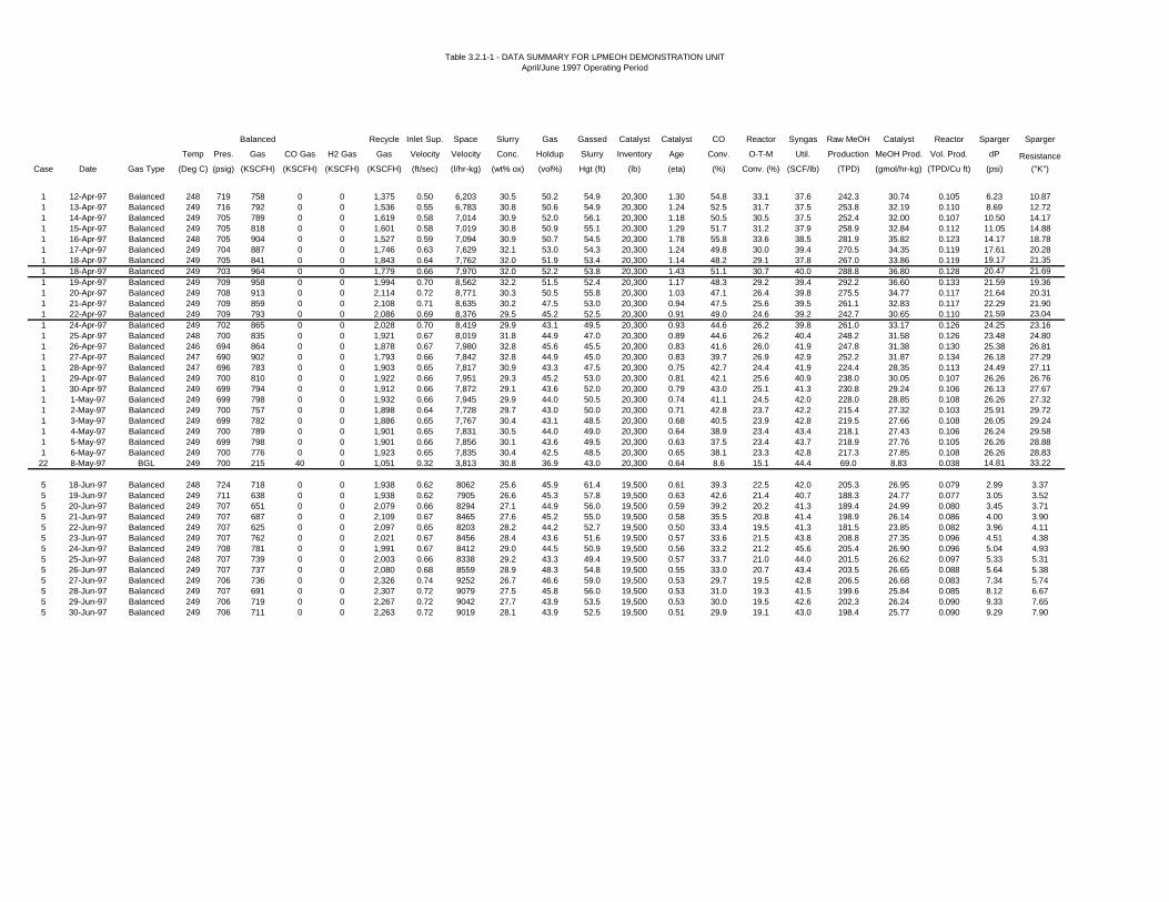
Table 3.2.1-1 - DATA SUMMARY FOR LPMEOH DEMONSTRATION UNITApril/June 1997 Operating Period
Balanced Recycle Inlet Sup. Space Slurry Gas Gassed Catalyst Catalyst CO Reactor Syngas Raw MeOH Catalyst Reactor Sparger Sparger
Temp Pres. Gas CO Gas H2 Gas Gas Velocity Velocity Conc. Holdup Slurry Inventory Age Conv. O-T-M Util. Production MeOH Prod. Vol. Prod. dP Resistance
Case Date Gas Type (Deg C) (psig) (KSCFH) (KSCFH) (KSCFH) (KSCFH) (ft/sec) (l/hr-kg) (wt% ox) (vol%) Hgt (ft) (lb) (eta) (%) Conv. (%) (SCF/lb) (TPD) (gmol/hr-kg) (TPD/Cu ft) (psi) ("K")
1 12-Apr-97 Balanced 248 719 758 0 0 1,375 0.50 6,203 30.5 50.2 54.9 20,300 1.30 54.8 33.1 37.6 242.3 30.74 0.105 6.23 10.871 13-Apr-97 Balanced 249 716 792 0 0 1,536 0.55 6,783 30.8 50.6 54.9 20,300 1.24 52.5 31.7 37.5 253.8 32.19 0.110 8.69 12.721 14-Apr-97 Balanced 249 705 789 0 0 1,619 0.58 7,014 30.9 52.0 56.1 20,300 1.18 50.5 30.5 37.5 252.4 32.00 0.107 10.50 14.171 15-Apr-97 Balanced 249 705 818 0 0 1,601 0.58 7,019 30.8 50.9 55.1 20,300 1.29 51.7 31.2 37.9 258.9 32.84 0.112 11.05 14.881 16-Apr-97 Balanced 248 705 904 0 0 1,527 0.59 7,094 30.9 50.7 54.5 20,300 1.78 55.8 33.6 38.5 281.9 35.82 0.123 14.17 18.781 17-Apr-97 Balanced 249 704 887 0 0 1,746 0.63 7,629 32.1 53.0 54.3 20,300 1.24 49.8 30.0 39.4 270.5 34.35 0.119 17.61 20.281 18-Apr-97 Balanced 249 705 841 0 0 1,843 0.64 7,762 32.0 51.9 53.4 20,300 1.14 48.2 29.1 37.8 267.0 33.86 0.119 19.17 21.351 18-Apr-97 Balanced 249 703 964 0 0 1,779 0.66 7,970 32.0 52.2 53.8 20,300 1.43 51.1 30.7 40.0 288.8 36.80 0.128 20.47 21.691 19-Apr-97 Balanced 249 709 958 0 0 1,994 0.70 8,562 32.2 51.5 52.4 20,300 1.17 48.3 29.2 39.4 292.2 36.60 0.133 21.59 19.361 20-Apr-97 Balanced 249 708 913 0 0 2,114 0.72 8,771 30.3 50.5 55.8 20,300 1.03 47.1 26.4 39.8 275.5 34.77 0.117 21.64 20.311 21-Apr-97 Balanced 249 709 859 0 0 2,108 0.71 8,635 30.2 47.5 53.0 20,300 0.94 47.5 25.6 39.5 261.1 32.83 0.117 22.29 21.901 22-Apr-97 Balanced 249 709 793 0 0 2,086 0.69 8,376 29.5 45.2 52.5 20,300 0.91 49.0 24.6 39.2 242.7 30.65 0.110 21.59 23.041 24-Apr-97 Balanced 249 702 865 0 0 2,028 0.70 8,419 29.9 43.1 49.5 20,300 0.93 44.6 26.2 39.8 261.0 33.17 0.126 24.25 23.161 25-Apr-97 Balanced 248 700 835 0 0 1,921 0.67 8,019 31.8 44.9 47.0 20,300 0.89 44.6 26.2 40.4 248.2 31.58 0.126 23.48 24.801 26-Apr-97 Balanced 246 694 864 0 0 1,878 0.67 7,980 32.8 45.6 45.5 20,300 0.83 41.6 26.0 41.9 247.8 31.38 0.130 25.38 26.811 27-Apr-97 Balanced 247 690 902 0 0 1,793 0.66 7,842 32.8 44.9 45.0 20,300 0.83 39.7 26.9 42.9 252.2 31.87 0.134 26.18 27.291 28-Apr-97 Balanced 247 696 783 0 0 1,903 0.65 7,817 30.9 43.3 47.5 20,300 0.75 42.7 24.4 41.9 224.4 28.35 0.113 24.49 27.111 29-Apr-97 Balanced 249 700 810 0 0 1,922 0.66 7,951 29.3 45.2 53.0 20,300 0.81 42.1 25.6 40.9 238.0 30.05 0.107 26.26 26.761 30-Apr-97 Balanced 249 699 794 0 0 1,912 0.66 7,872 29.1 43.6 52.0 20,300 0.79 43.0 25.1 41.3 230.8 29.24 0.106 26.13 27.671 1-May-97 Balanced 249 699 798 0 0 1,932 0.66 7,945 29.9 44.0 50.5 20,300 0.74 41.1 24.5 42.0 228.0 28.85 0.108 26.26 27.321 2-May-97 Balanced 249 700 757 0 0 1,898 0.64 7,728 29.7 43.0 50.0 20,300 0.71 42.8 23.7 42.2 215.4 27.32 0.103 25.91 29.721 3-May-97 Balanced 249 699 782 0 0 1,886 0.65 7,767 30.4 43.1 48.5 20,300 0.68 40.5 23.9 42.8 219.5 27.66 0.108 26.05 29.241 4-May-97 Balanced 249 700 789 0 0 1,901 0.65 7,831 30.5 44.0 49.0 20,300 0.64 38.9 23.4 43.4 218.1 27.43 0.106 26.24 29.581 5-May-97 Balanced 249 699 798 0 0 1,901 0.66 7,856 30.1 43.6 49.5 20,300 0.63 37.5 23.4 43.7 218.9 27.76 0.105 26.26 28.881 6-May-97 Balanced 249 700 776 0 0 1,923 0.65 7,835 30.4 42.5 48.5 20,300 0.65 38.1 23.3 42.8 217.3 27.85 0.108 26.26 28.83
22 8-May-97 BGL 249 700 215 40 0 1,051 0.32 3,813 30.8 36.9 43.0 20,300 0.64 8.6 15.1 44.4 69.0 8.83 0.038 14.81 33.22
5 18-Jun-97 Balanced 248 724 718 0 0 1,938 0.62 8062 25.6 45.9 61.4 19,500 0.61 39.3 22.5 42.0 205.3 26.95 0.079 2.99 3.375 19-Jun-97 Balanced 249 711 638 0 0 1,938 0.62 7905 26.6 45.3 57.8 19,500 0.63 42.6 21.4 40.7 188.3 24.77 0.077 3.05 3.525 20-Jun-97 Balanced 249 707 651 0 0 2,079 0.66 8294 27.1 44.9 56.0 19,500 0.59 39.2 20.2 41.3 189.4 24.99 0.080 3.45 3.715 21-Jun-97 Balanced 249 707 687 0 0 2,109 0.67 8465 27.6 45.2 55.0 19,500 0.58 35.5 20.8 41.4 198.9 26.14 0.086 4.00 3.905 22-Jun-97 Balanced 249 707 625 0 0 2,097 0.65 8203 28.2 44.2 52.7 19,500 0.50 33.4 19.5 41.3 181.5 23.85 0.082 3.96 4.115 23-Jun-97 Balanced 249 707 762 0 0 2,021 0.67 8456 28.4 43.6 51.6 19,500 0.57 33.6 21.5 43.8 208.8 27.35 0.096 4.51 4.385 24-Jun-97 Balanced 249 708 781 0 0 1,991 0.67 8412 29.0 44.5 50.9 19,500 0.56 33.2 21.2 45.6 205.4 26.90 0.096 5.04 4.935 25-Jun-97 Balanced 248 707 739 0 0 2,003 0.66 8338 29.2 43.3 49.4 19,500 0.57 33.7 21.0 44.0 201.5 26.62 0.097 5.33 5.315 26-Jun-97 Balanced 249 707 737 0 0 2,080 0.68 8559 28.9 48.3 54.8 19,500 0.55 33.0 20.7 43.4 203.5 26.65 0.088 5.64 5.385 27-Jun-97 Balanced 249 706 736 0 0 2,326 0.74 9252 26.7 46.6 59.0 19,500 0.53 29.7 19.5 42.8 206.5 26.68 0.083 7.34 5.745 28-Jun-97 Balanced 249 707 691 0 0 2,307 0.72 9079 27.5 45.8 56.0 19,500 0.53 31.0 19.3 41.5 199.6 25.84 0.085 8.12 6.675 29-Jun-97 Balanced 249 706 719 0 0 2,267 0.72 9042 27.7 43.9 53.5 19,500 0.53 30.0 19.5 42.6 202.3 26.24 0.090 9.33 7.655 30-Jun-97 Balanced 249 706 711 0 0 2,263 0.72 9019 28.1 43.9 52.5 19,500 0.51 29.9 19.1 43.0 198.4 25.77 0.090 9.29 7.90

TPR12C.DOC Apr. - Jun. 97 Page 25 of 46 06/09/98
292.2 TPD); for shorter balance periods (approximately 12 hours), methanol production ratesof 92,900 to 94,500 gallons per day (302 to 307 TPD) were measured.
During the first days of operation, several strainers in the reactor loop became blocked withdebris remaining in the piping systems from construction and hydrotesting. Outages weretaken to clean screens at the inlet to the 29C-40 carbonyl guard bed and the 29C-03 high-pressure methanol separator. The carbonyl guard bed was bypassed from 04 April 1997 until18 April 1997; the decision to bypass the carbonyl guard bed was based upon the results ofthe carbonyl survey completed in March (as reported in Technical Progress Report No. 11)and an autoclave test performed at the Kingsport site in May/June 1996. A draft TopicalReport has been issued on that study (Design and Construction of the Alternative Fuels FieldTest Unit and Liquid Phase Methanol Feedstock and Catalyst Life Testing at EastmanChemical Company (Kingsport, TN)).
As noted in Technical Progress Report No. 11, the 29G-03 oil make-up pumps were unableto deliver fresh oil to the reactor loop at the required pressure of approximately 700 psig.These pumps also provide the required high pressure seal flush to the 29G-01 condensed oilcirculation pumps, which return oil and catalyst collected in the 29C-06 cyclone and the 29C-05 secondary oil knock-out drum to the reactor (refer to Appendix A for the simplifiedprocess flow diagram). One of the features included in the design of the LPMEOHDemonstration Unit was the capability to free-drain condensed and entrained oil and catalystslurry back to the reactor. Furthermore, fresh make-up oil could be added to the process byusing the 29G-30 slurry transfer pump, which was designed to transfer catalyst slurry fromthe 29C-30 catalyst reduction vessel to the reactor. Oil was batch-transferred from the 29D-30 oil storage tank to the catalyst reduction vessel, and then pumped to the reactor by theslurry transfer pump. The slurry transfer pump has packing which also requires flush fromthe oil make-up pumps; however, it was determined that operation of the slurry transferpump in services with clean oil or low solids concentration would not adversely affect theservice life of the pump.
The free-drain line showed intermittent plugging or vapor-locking during operation. Early inthe operating campaign, blockages could be cleared by opening a transfer line between thesecondary oil knock-out drum and catalyst reduction vessel and briefly blowing down to lowpressure; piping connections to provide flush oil were rendered useless by the inoperable oilmake-up pumps. However, on 25 April 1997, a blockage in the free-drain line occurred in alocation which could not be removed by this method. Since the slurry concentration of theentrained oil and catalyst was relatively low, it was determined that the slurry transfer pumpcould pump this material without packing flush on the pump. Condensed oil was batch-transferred from the secondary oil knock-out drum to the catalyst reduction vessel, and thenpumped to the reactor. The frequency of the transfer to the catalyst reduction vessel wasabout every 3 hours, and the catalyst reduction vessel was pumped to the reactor about every10 hours. The rate of accumulation of entrained/condensed slurry (1.5 to 2.0 gallons perminute) matched the expected liquid traffic within the oil/catalyst collection equipment.
A two-day test using a CO-rich reactor feed (H2/CO = 0.43) was performed on 07-08 May1997. The Test Authorization for this trial is included in Appendix K. At the conclusion ofthis test, the LPMEOH Demonstration Unit was shut down in preparation for a biannual

TPR12C.DOC Apr. - Jun. 97 Page 26 of 46 06/09/98
outage at the Eastman coal-to-chemicals facility. Catalyst slurry was pressure-transferredfrom the reactor to the slurry storage tank for storage under a reducing atmosphere duringthe outage.
Throughout this initial operating period, pressure-drop measurements across the gas spargerat the bottom of the reactor showed a steady increase during normal operation. Pressuredrop can be expressed in the following equation:
∆P = K ∗ (V * MW)2
ρ
where: ∆P = pressure drop across sparger, pounds per square inch K = sparger resistance coefficient V = vapor volumetric flowrate, thousand standard cubic feet per hourMW = vapor molecular weight, pounds per pound mole ρ = vapor density, pounds per cubic foot
This equation shows that pressure drop readings can be influenced by changes in gas flowrateand/or gas composition. The resistance coefficient (K) can be used to determine any changein the vapor flow path through the gas sparger. For a given vapor volumetric flowrate anddensity, an increase in K (caused by a restriction in the flow path, for example), will result inan increase in pressure drop.
Appendix I, Figure 1 plots K over time since the start-up of the LPMEOH DemonstrationUnit. (Note that K as reported contains an arbitrary factor to make the value moremanageable, and therefore has meaning only in a relative sense.) The data for this plot, alongwith the corresponding pressure drop measurement, are included in Table 3.2.1-1. Pressuredrop and resistance increased with time on stream, and extended periods with no vapor flowthrough the gas sparger (noted on Figure 1) appear to have no impact on this trend.
Maintenance Activities During May/June 1997 Complex Outage
Most of the activities in the LPMEOH Demonstration Unit during the complex outagefocused on the inspection of equipment associated with the reactor, particularly the gassparger. About 800 pounds of residual catalyst was removed from the bottom head of thereactor during this exercise. A solid material (presumably methanol synthesis catalyst)appeared to block about 50% of the flow path through the sparger; a small amount of catalystwas found in the inlet piping to the sparger. There was no discernible pattern to the blockageby the catalyst, and no significant construction debris was found in the inlet piping or in thesparger. The sparger was removed from the reactor and cleaned. The only modifications tothe sparger itself were changes to increase the maximum allowable pressure drop; no changeto the flow distribution characteristics was made.
Another effect of the commissioning problems associated with the oil make-up pumps is theloss of oil flush provided by the condensed oil circulation pumps to the walls of the cyclone.At the LaPorte AFDU, liquid flush to the cyclone improved the efficiency of solids removal.During the complex outage, the inlet to the tubesheet of the 29E-02 feed/product heat

TPR12C.DOC Apr. - Jun. 97 Page 27 of 46 06/09/98
exchanger (immediately downstream of the cyclone) was removed to check for catalystaccumulation. The tubesheet was generally clean except for a small, off-center accumulationon the upper left quadrant. The catalyst slightly obstructed the entrance to these tubes, butdid not completely block any tube. No catalyst was visible within any of the tubes. Thesurface catalyst was removed, and the feed/product heat exchanger was reassembled.
During the initial operating period, the blockage in the free-drain line provided evidence thatthe ability to flush piping systems in slurry service was an important operability requirement.Since a replacement for the oil make-up pumps had not yet been identified, the slurry transferpump was connected into the flush piping system originally designed to be supplied by the oilmake-up pumps. A flush connection was also added to the gas inlet line to the reactor; thiscould be used to flush out the piping and gas sparger during normal operation, at those timeswhen gas flow to the reactor is lost, or in preparation for maintenance.
Other maintenance activities focused on repair of minor leaks in the steam system.
Unit Restart and Operation - 17-30 June 1997
After the catalyst slurry was pressure-transferred from the slurry storage tank to the reactor,the reactor was heated using 600 psig steam in the same manner as the April start-up.Balanced Gas was introduced to the LPMEOH Demonstration Unit at 1400 hours on 17June 1997. Operation of the facility has continued uninterrupted since the restart. The free-drain piping from the secondary oil knock-out drum and cyclone to the reactor plugged againshortly after restart, but flush oil from the slurry transfer pump successfully dislodged theblockage.
Again, the gas sparger has shown an increase in pressure drop and resistance since the restart,although not as rapidly as during the April-May operation. The plot of sparger resistancecoefficient with time for both operating periods is provided in Appendix I, Figure 1. Thevalue for the resistance coefficient is lower for the latest start-up of the reactor; this may be aresult of additional attention to maintaining vapor flow through the sparger during the slurrytransfer operation. On 26 June 1997, fresh oil from the slurry transfer pump was introducedfor the first time to the new flush connection on the gas inlet line to the reactor; the flushlowered the pressure drop from 5.5 psi to 4.5 psi. However, the effects were temporary, andthe resistance coefficient continued to increase. Additional flushing with both fresh oil andentrained slurry will be attempted in order to stabilize the resistance coefficient. Fresh oil canonly be added to the process at an average of 0.1 - 0.2 gallons per minute to match the rateof oil loss with the methanol product; entrained slurry can be supplied at the rate of liquidtraffic in the secondary oil knock-out drum and cyclone (1.5 to 2.0 gallons per minute).
Catalyst Life (eta)
The activity of the methanol synthesis catalyst can be expressed in terms of a dimensionlessvariable eta (η), which is defined as the ratio of the rate constant at any point in time to therate constant for a freshly reduced catalyst (as determined in the laboratory autoclave).Appendix I, Figure 2 contains the plot for η versus days onstream since the start-up in Aprilof 1997; shutdowns of the LPMEOH™ Demonstration Unit are indicated and match the

TPR12C.DOC Apr. - Jun. 97 Page 28 of 46 06/09/98
longer interruptions in operation from Appendix I, Table 1. During the April/May 1997operating period, the evidence was unclear whether the decline in η was a result of a declinein catalyst activity or hydrodynamic effects related to the increase in resistance coefficient forthe gas sparger. Upon restarting the LPMEOH™ Demonstration Unit in June of 1997, thevalue of η was determined to be unaffected by the magnitude of the sparger resistancecoefficient. It appears that catalyst activity is declining more rapidly than expected.
A catalyst slurry sample was taken during the May/June 1997 complex outage. Due to achange in procedures for handling reduced catalyst in the laboratory, analysis of this samplefor copper crystallite size, surface area, and the presence of catalyst poisons will not beperformed until July of 1997.
Overall, the LPMEOH™ Demonstration Unit operated well during the initial campaign. Theavailability of the LPMEOH™ Demonstration Unit was 94.9% during the reporting period.All methanol produced (a total of 2,900,692 gallons) was used by Eastman in the productionof methyl acetate, and ultimately cellulose acetate and acetic acid. The start-up wassuccessfully completed in a safe and environmentally sound manner.
Methods of Calculation
As described in Section 6.2 of the Demonstration Test Plan, a comprehensive set of theformulas used to calculate key performance parameters of the LPMEOH™ Process was to beincluded in the first Technical Progress Report for Task 3.2.1 - Methanol Operation. Thesecalculations are provided in Appendix L.
Task 3.2.2 DME Design, Modification and Operation
No activities occurred in this Task during the reporting period.
Task 3.3 On-Site Testing (Product-Use Demonstration)
No activities occurred in this Task during the reporting period.
Task 3.4 Off-Site Testing (Product-Use Demonstration)
No activities occurred in this Task during the reporting period.
Task 3.5 Data Analysis and Reports
The results of the data analysis for the operation of the LPMEOH™ Demonstration Unit arereported under Task 3.2.1 (Methanol Operation).
Task 3.6 Planning and Administration

TPR12C.DOC Apr. - Jun. 97 Page 29 of 46 06/09/98
An interim project review meeting was held on 29 and 30 April 1997 in Allentown.Attendees from Air Products and DOE participated. An update on the performance of thedemonstration unit was provided. The catalyst targets and corresponding economics for acommercially successful LPDME catalyst were reviewed; these and other comments fromDOE were incorporated into the DME recommendation (issued 30 June 1997). The status ofthe updated product-use test plan was also discussed. The meeting agenda, extracts from themeeting handouts, and the meeting notes are included in Appendix M.
The Milestone Schedule Status Report and the Cost Management Report, through the periodending 30 June 1997, are included in Appendix N. These two reports show the currentschedule, the percentage completion and the latest cost forecast for each of the WorkBreakdown Structure (WBS) tasks. The demonstration unit was mechanically complete on31 January 1997. Ninety-eight percent (98%) of the $38 million of funds forecast for theKingsport portion of the LPMEOH Process Demonstration Project for the Phase 1 andPhase 2 tasks have been expended (as invoiced), as of 30 June 1997. Five percent (5%) ofthe $158 million of funds for the Phase 3 tasks have been expended (as invoiced), as of 30June 1997.
Start-up activities were completed during the reporting period, and the initial methanolproduction from the demonstration unit occurred on 02 April 1997. The first extended stableoperation at the nameplate capacity of 80,000 gallons per day (260 TPD) took place on 06April 1997. The demonstration unit was shut down on 08 May 1997 as part of a scheduledcomplex outage for the Kingsport site. After completion of maintenance activities, thedemonstration unit was restarted on 17 June 1997, and maintained stable operation throughthe remainder of the reporting period. Details of the operating activities are provided underTask 3.2 of this report.
Preparations for the plant dedication ceremony, scheduled for 25 July 1997, began in earnest.Participants are expected to include senior management from Air Products, Eastman, andDOE.
A press release on the start-up of the LPMEOH™ Demonstration Facility was issued on 21May 1997. A copy of the press release, as well as a sample of other publications whichreported on the start-up of the demonstration unit, are included in Appendix O.
An update of the Project Management Plan was submitted to DOE on 30 June 1997. Thisversion summarizes the reporting structure during Tasks 1 and 2, and lists the current teammembers for Air Products, Eastman, and Acurex.
The monthly reports for April, May, and June were submitted. These reports include theMilestone Schedule Status Report, the Project Summary Report, and the Cost ManagementReport. All Quarterly Technical Progress Reports through 31 March 1997 have beenapproved by DOE. DOE and Air Products agreed to delay the publication of theDemonstration Technology Start-up Report until issues related to the oil make-up pump andthe reactor sparger have been resolved (refer to Task 3.2 for the status of these items).

TPR12C.DOC Apr. - Jun. 97 Page 30 of 46 06/09/98
E. Planned Activities for the Next Quarter
• Resolve any issues associated with the gas sparger in the reactor and with the oil
make-up pumps. Upon resolution of these items, write and submit the Demonstration
Technology Start-up Report to DOE.
• Analyze catalyst slurry sample taken during May/June 1997 complex outage to
determine causes for deactivation of methanol synthesis catalyst.
• Continue executing Phase 3, Task 2.1 Methanol Operation per the Demonstration
Test Plan.
• Receive concurrence from DOE on the DVT Recommendation for a DME proof-of-
concept test run at the LaPorte AFDU.
• Receive concurrence from DOE on the Off-Site, Product-Use Test Plan (Phase 1,
Task 1.4).
• Hold a Project Review Meeting in Kingsport in July, in conjuntion with the 25 July
dedication ceremony.
• Incorporate DOE comments into the Topical Report on Process Economic Studies.
F. Conclusion
During this quarter, comments from the DOE on the Topical Report “Economic Analysis -LPMEOH™ Process as an Add-on to IGCC for Coproduction” were received. The studyconcludes that methanol coproduction, with IGCC electric power utilizing the LPMEOHprocess technology, will be competitive in serving local market needs.
A recommendation to continue with DME design verification testing was made. DME designverification testing studies show the liquid phase DME (LPDME) process will have asignificant economic advantage for the coproduction of DME for local markets. The marketapplications for DME are large. An LPDME catalyst system with reasonable long-termactivity and stability is being developed. Planning for a proof-of-concept test run at theLaPorte Alternative Fuels Development Unit (AFDU) was recommended. Arecommendation document summarizing catalyst targets, experimental results, and thecorresponding economics for a commercially successful LPDME catalyst was issued on 30June 1997.
The off-site, product-use test plan was updated in June of 1997. During this quarter, Acurexand Air Products screened proposals for this task by the likelihood of the projects to proceedand the timing for the initial methanol requirement. Eight sites from the list have met thesecriteria. The formal submission of the eight projects for review and concurrence by the DOEwill be made during the next reporting period.

TPR12C.DOC Apr. - Jun. 97 Page 31 of 46 06/09/98
An interim project review meeting was held in Allentown in late April of 1997. An update onthe performance of the demonstration unit was provided, and the status of the DMErecommendation and the off-site product-use test plan were discussed.
The site paving and final painting were completed in May of 1997. Start-up activities werecompleted during the reporting period, and the initial methanol production from thedemonstration unit occurred on 02 April 1997. The first extended stable operation at thenameplate capacity of 80,000 gallons per day (260 TPD) took place on 06 April 1997.Pressure drop and resistance coefficient across the gas sparger at the bottom of the reactorincreased over this initial operating period. The demonstration unit was shut down on 08May 1997 as part of a scheduled complex outage for the Kingsport site. During this outage,the gas sparger was removed, cleaned, and reinstalled. After completion of othermaintenance activities, the demonstration unit was restarted on 17 June 1997, and maintainedstable operation through the remainder of the reporting period. Again, the gas spargershowed an increase in pressure drop and resistance since the restart, although not as rapidlyas during the April-May operation. Fresh oil was introduced for the first time to a new flushconnection on the vapor inlet line to the reactor; the flush lowered the pressure drop by 1 psi.However, the effects were temporary, and the sparger resistance coefficient continued toincrease. Additional flushing with both fresh oil and entrained slurry will be attempted inorder to stabilize the sparger resistance coefficient.
Catalyst activity, as defined by the ratio of the rate constant at any point in time to the rateconstant for a freshly reduced catalyst (as determined in the laboratory autoclave), declinedmore rapidly than expected. A catalyst slurry sample was taken during the May/June 1997complex outage for analysis.
Overall, the LPMEOH™ Demonstration Unit operated well during the initial campaign. Theavailability of the LPMEOH™ Demonstration Unit was 94.9% during the reporting period.All methanol produced (a total of 2,900,692 gallons) was used by Eastman in the productionof methyl acetate, and ultimately cellulose acetate and acetic acid. The start-up wassuccessfully completed in a safe and environmentally sound manner.
Ninety-eight percent (98%) of the $38 million of funds forecast for the Kingsport portion ofthe LPMEOH Process Demonstration Project for the Phase 1 and Phase 2 tasks have beenexpended (as invoiced), as of 30 June 1997. Five percent (5%) of the $158 million of fundsfor the Phase 3 tasks have been expended (as invoiced), as of 30 June 1997.

TPR12C.DOC Apr. - Jun. 97 Page 32 of 46 06/09/98
APPENDICES
APPENDIX A - SIMPLIFIED PROCESS FLOW DIAGRAM

TPR12C.DOC Apr. - Jun. 97 Page 33 of 46 06/09/98
APPENDIX B - PROJECT EVALUATION PLAN FOR BUDGET PERIOD NO. 2

TPR12C.DOC Apr. - Jun. 97 Page 34 of 46 06/09/98
APPENDIX C - TASK 1.4 - OFF-SITE TESTING (DEFINITION AND DESIGN)
Synopsis of All Proposals (twenty pages)
and
Summary Table of Eight Candidates (one page)

TPR12C.DOC Apr. - Jun. 97 Page 35 of 46 06/09/98
APPENDIX D - TASK 1.5.2 - PROCESS ECONOMIC STUDY
Process Economics Study - Outline(Draft - 3/31/97 - four pages)
and
LPMEOH Process Economics - for IGCC Coproduction(Memo - 31 March 1997 - two pages)

TPR12C.DOC Apr. - Jun. 97 Page 36 of 46 06/09/98
APPENDIX E - TASK 1.5.3 - DME DESIGN VERIFICATION TESTING

TPR12C.DOC Apr. - Jun. 97 Page 37 of 46 06/09/98
APPENDIX F - TASK 1.5.4 - APPROVAL FOR BUDGET PERIOD THREE

TPR12C.DOC Apr. - Jun. 97 Page 38 of 46 06/09/98
APPENDIX G - TASK 2.5 - PARTNERSHIP ANNUAL PLAN(For FY - 97)

TPR12C.DOC Apr. - Jun. 97 Page 39 of 46 06/09/98
APPENDIX H - TEST AUTHORIZATION #K1 - INITIAL SHAKEDOWN ANDDESIGN PRODUCTION TESTS

TEST AUTHORIZATION # K1Kingsport LPMEOH Plant
Sheet: 1 of 3Date : 03/31/97By: VES
RUN NUMBER: K1 (also incorporating K7)APPROX. START DATE: 1 April, 1997
TITLE: METHANOL SYNTHESIS WITH BASELINE CATALYST:INITIAL SHAKEDOWN AND DESIGN PRODUCTION TESTS
OBJECTIVE:To start-up the LPMEOH facility, test the design methanol production rate, and shakedown varioussystems critical to successful long-term operation of the plant.
SUMMARY:After activation of the initial catalyst charge (approximately 20,000 lbs of catalyst oxide, or about 1/2 ofthe design catalyst loading in the reactor), the start-up of methanol operations will initiate a total systemshakedown and test of the design methanol production rate of 260 TPD. This 6-week operating periodprior to Eastman’s complex outage will facilitate testing of systems which must operate on a continuousbasis (e.g. recycle compression, carbonyl guard bed, reactor/steam system, oil collection and return,methanol collection and distillation, data acquisition, analytical, etc.). The process control strategy willbe validated and tuned, and material balance calculations will be performed. During this test, catalystactivity will decrease slowly due to normal catalyst aging. Fresh Feed flowrates will be adjusted tomaintain Syngas Utilization at its initial value.
TEST DETAILS: See pages 2 to 3 for details.
ANALYTICAL COMMENTS: See page 3.
SAFETY IMPLICATIONS:Air Products personnel will be required to wear Nomex in the plant when syngas is present. Otherwise,Eastman safety rules (including M.O.C.) are in effect. All visitors to the facility must follow the VisitorSafety Guidelines issued by the Joint Venture.
ENVIRONMENTAL IMPLICATIONS:Minimal. The plant syngas purge will go to the Eastman boilers as designed.
SPECIAL REMARKS:Because of ongoing problems with the 29G-03 Oil Make-up Pumps, which provide high pressure sealflush to the 29G-01 Condensed Oil Circulation Pumps and batch make-up oil into the reactor loop, Test#K1 will also incorporate Test #K7. The objective of Test #K7 is to test the capability of the system tofree-drain condensed and entrained oil/catalyst from the 29C-06 Cyclone and 29C-05 Secondary OilK.O. Separator back to the reactor. During this period the 29G-30 Slurry Transfer Pump will providemake-up oil to the process in batches as necessary. It requires only low pressure packing flush oil,which the 29G-03 can provide.
AUTHORIZATIONS:
E. C. Heydorn - Program Manager V. E. Stein - Lead Process Engineer

TEST AUTHORIZATION # K1Kingsport LPMEOH Plant
Sheet: 2 of 3Date : 03/31/97By: VES
TEST DETAILS:
1. Set up N2 purges to the vent header at 100 SCFH on each of the rotameters by the 29E-01 (FI-1970) and 29C-02 (FI-1115).
2. Follow the Reactor Area Start-Up Procedure S.O.P. Section II A 3. After the start-up preparationsteps (A-C), continue with Step D.
D. Charge fresh oil from 29D-30 to 29C-05 secondary oil K.O. vessel and 29C-06 cyclone.E. Place 29K-01 syngas recycle compressor in service.F. Transfer reduced catalyst slurry from 29D-02 slurry tank to the reactor (via 29G-02) per Section
IV A 9 Steps K, L, M, and N. The slurry temperature must not exceed ambient temperature by more than 165 °°C.
G. Start N2 Flow from 29K-01 to reactor.H. Start BFW to 29C-02 steam drum and reactor tubes.I. Start CW flow to 29E-04 MeOH product CW condenser.J. Start fans on 29E-03 MeOH product air-cooled condenser.K. Heat reactor to 204 °C at <30 °C/hr. Initially BFW / steam temperature should notexceed slurry temperature by more than 150 °°C. Once the slurry temperatureexceeds 125 °°C, BFW / steam temperature should not exceed slurrytemperature by more than 40 °°C.
3. Because condensed and entrained oil/catalyst will free-drain back to the reactor, omit Steps L-O.Instead, ensure that automatic valves HV-184 and HV-185 are both shut.
4. Continue with Step P.
P. Start fresh feed syngas to plant.Q. Establish level control for 29C-03 high pressure MeOH separator.
5. At Step R, raise the reactor pressure (PIC-150) and temperature (TIC-109) to the design operatingconditions: 735 psig and 250 °C. Set the syngas flow rate (FIC-009) at 990 KSCFH, and skipSteps S and T until Plant 19 lines out at reduced rates and the H2 Makeup composition reachesits new steady state. Eventually, new feed setpoints will be calculated for the CO and H2 Makeupstreams. Then, FIC-009 will be reduced by that combined flow rate to maintain total fresh feed at990 KSCFH. Set the compressor flow (FIC-008) at 1,760 KSCFH.
6. During the first 24 hours, the syngas conversion across the reactor may decrease as the catalystloses its initial hyperactivity. As a result, the purge flow (FI-157) may increase. Eventually, thepurge rate should be about 160 KSCFH.
7. To free-drain condensed and entrained oil/catalyst from 29C-05 and 29C-06 to the reactor, openHV-185 and the necessary manual valves. Monitor levels in the 29C-05 (LI-102) and 29C-06 (LI-152), as well as the reactor NDG.

TEST AUTHORIZATION # K1Kingsport LPMEOH Plant
Sheet: 3 of 3Date : 03/31/97By: VES
8. Until the 29G-03 pumps are repaired, oil will be batch transferred into the system as needed bythe 29G-30 pump per S.O.P. Section II C 3 Step P.
9. The shakedown period will likely conclude with the Eastman complex outage in mid-May. In thatevent, purge, cool, and drain the reactor system according to the Reactor Area ExtendedShutdown Procedure (S.O.P. Section II A 8).
TEST AUTHORIZATION #K1 is complete.
ANALYTICAL REQUIREMENTS:
1. Process GC sampling requirements:
- SP-1: syngas feed;- SP-4: K-01 outlet;- SP-5: reactor feed (highest frequency);- SP-6: C-05 outlet (highest frequency);- SP-7: main purge;- SP-8: distillation purge;
- SP-2 and SP-3 can remain valved out until required.
2. Carbonyl GC sampling requirements:
- SP-12: 29C-40 guard bed inlet;- SP-13: 29C-40 guard bed intermediate #1;- SP-14: 29C-40 guard bed intermediate #2;- SP-15: 29C-40 guard bed outlet.
3. Liquid sampling requirements:
- all identified liquid sampling points per standard Eastman routine.

TPR12C.DOC Apr. - Jun. 97 Page 40 of 46 06/09/98
APPENDIX I - TASK 3.2.1 - RESULTS OF DEMONSTRATION PLANTOPERATION
Table 1 - Summary of LPMEOH™ Demonstration Unit Outages - April/June 1997
Figure 1 - Sparger Resistance Coefficient vs. Days Onstream - April/June 1997 Operating PeriodFigure 2 - Catalyst Life (ηη) vs. Days Onstream

Table 1 - Summary of LPMEOHTM Demonstration Unit Outages - April/June 1997
Operating ShutdownOperation Start Operation End Hours Hours Reason for Shutdown
4/2/97 09:00 4/2/97 16:15 7.3 4.8 Syngas Unavailable to LPMEOHTM Demonstration Unit4/2/97 21:05 4/2/97 21:25 0.3 23.3 Liquids to K-014/3/97 20:40 4/4/97 11:00 14.3 24.8 Syngas Unavailable to LPMEOHTM Demonstration Unit4/5/97 11:45 4/6/97 01:45 13.0 5.8 C-03 Outlet Plugged4/6/97 07:30 4/7/97 13:05 29.6 2.1 C-03 Outlet Plugged4/7/97 15:10 4/8/97 06:30 15.3 21.5 Syngas Unavailable to LPMEOHTM Demonstration Unit4/9/97 04:00 4/9/97 05:30 1.5 4.0 ESD on C-02 Level4/9/97 09:30 4/9/97 14:20 4.8 9.7 Syngas Unavailable to LPMEOHTM Demonstration Unit
4/10/97 00:00 4/11/97 08:25 32.4 14.8 Syngas Unavailable to LPMEOHTM Demonstration Unit4/11/97 23:15 4/18/97 18:05 162.8 0.7 Syngas Unavailable to LPMEOHTM Demonstration Unit4/18/97 18:45 4/19/97 07:50 13.1 0.7 Syngas Unavailable to LPMEOHTM Demonstration Unit4/19/97 08:30 4/23/97 00:20 87.8 20.7 Replace TV-101 Trim4/23/97 21:00 4/23/97 21:00 0.0 12.0 * Syngas Unavailable to LPMEOHTM Demonstration Unit4/24/97 09:00 5/8/97 23:59 351.0 950.1 ** Syngas Unavailable to LPMEOHTM Demonstration Unit6/17/97 14:05 6/30/97 23:59 321.9 End of Reporting Period
Total Operating Hours 1055.2Syngas Available Hours 1111.0Plant Availability, % 95.0
* Plant was ready to startup, but Eastman waited 12 hours to give the day crew trainingon startup procedures.
** Eastman complex outage.

TPR12C.DOC Apr. - Jun. 97 Page 41 of 46 06/09/98
APPENDIX J - TASK 3.2.1 - SAMPLES OF DETAILED MATERIAL BALANCEREPORTS

TPR12C.DOC Apr. - Jun. 97 Page 42 of 46 06/09/98
APPENDIX K - TEST AUTHORIZATION K22 - METHANOL SYNTHESIS WITHBGL-TYPE SYNGAS

TEST AUTHORIZATION # K22Kingsport LPMEOH Plant
Sheet: 1 of 2Date : 05/07/97By: VES
RUN NUMBER: K22APPROX. START DATE: 7 May, 1997
TITLE: METHANOL SYNTHESIS WITH BGL-TYPE SYNGAS
OBJECTIVE:To evaluate the performance of the LPMEOH facility when fed with BGL-type (CO-rich) syngas per atypical IGCC application.
SUMMARY:At a time when approximately 200 KSCFH of CO is available for use in Plant 29 over a multi-weekperiod, the reactor feed composition will be adjusted to match the typical syngas composition exiting aBGL gasifier. The performance data from this test will be more directly comparable to the extensivedatabase from the LaPorte pilot plant and more indicative of LPMEOHTM’s expected market in IGCCfacilities. The test will best be accomplished by maintaining essentially constant feed gas composition(SP-5), and the operators may adjust the Balanced Gas, CO Gas, and Recycle flow rates to achievethat. Liquid samples from the 29C-10 underflow should be collected periodically to test the stabilizedproduct’s suitability for fuel-grade applications.
TEST DETAILS: See page 2.
ANALYTICAL COMMENTS: See page 2.
SAFETY IMPLICATIONS:Air Products personnel will be required to wear Nomex in the plant when syngas is present. Otherwise,Eastman safety rules (including M.O.C.) are in effect. All visitors to the facility must follow the VisitorSafety Guidelines issued by the Joint Venture.
ENVIRONMENTAL IMPLICATIONS:Minimal. The plant syngas purge will go to the Eastman boilers as designed.
SPECIAL REMARKS:Because of ongoing problems with plugging in the free-draining oil return line to the reactor, the currentoff-design operating mode will be continued. Condensed oil will be batch transferred from 29C-05 to29C-30 and then returned to the reactor with the 29G-30 pump.
AUTHORIZATIONS:
E. C. Heydorn - Program Manager V. E. Stein - Lead Process Engineer

TEST AUTHORIZATION # K22Kingsport LPMEOH Plant
Sheet: 2 of 2Date : 05/07/97By: VES
TEST DETAILS:
1. Call the PIA’s and have them set up SP-2 (CO Makeup) and add it to the analysis sequence.
2. Follow the Reactor Area Start-Up Procedure S.O.P. Section II A 3 Step T - start CO makeup feed.
3. Line up CO flow through FE-010B (open valve 2025) and shut off flow through FE-010A (closevalve 2026). Make sure the Honeywell DCS is set up to recognize FE-010B.
4. Slowly increase the flow on FC-010 to approximately 200 KSCFH while decreasing the flow onFC-009 to approximately 485 KSCFH. As the MW of the recycle stream begins to rise, thecompressor flow will increase. Adjust it to maintain approximately 1570 KSCFH on FI-100.
5. The target feed gas composition (SP-5) in mol% (Honeywell schematic AnalD or AnalB) is: 32%H2, 61% CO, 5% CO2 , 1% N2. In wt% (Honeywell schematic Anal_D or Anal_B), this correspondsto 3% H2 , 83% CO, 11% CO2 , 2% N2. Be patient when adjusting flows to match the targetcomposition; Air Products personnel will advise.
TEST AUTHORIZATION #K22 is complete.
ANALYTICAL REQUIREMENTS:
1. Process GC sampling requirements:
- SP-1: syngas feed;- SP-2: CO makeup- SP-4: K-01 outlet;- SP-5: reactor feed (highest frequency);- SP-6: C-05 outlet (highest frequency);- SP-7: main purge;- SP-8: distillation purge;
- SP-3 can remain valved out.
2. Carbonyl GC sampling requirements:
- SP-12: 29C-40 guard bed inlet;- SP-13: 29C-40 guard bed intermediate #1;- SP-14: 29C-40 guard bed intermediate #2;- SP-15: 29C-40 guard bed outlet.
3. Liquid sampling requirements:
- all identified liquid sampling points per standard Eastman routine;

TEST AUTHORIZATION # K22Kingsport LPMEOH Plant
Sheet: 3 of 2Date : 05/07/97By: VES
- 29C-10 underflow samples may be shipped to Allentown for by-product analysis.

TPR12C.DOC Apr. - Jun. 97 Page 43 of 46 06/09/98
APPENDIX L - METHODS OF CALCULATION FOR KEY PROCESSPARAMETERS
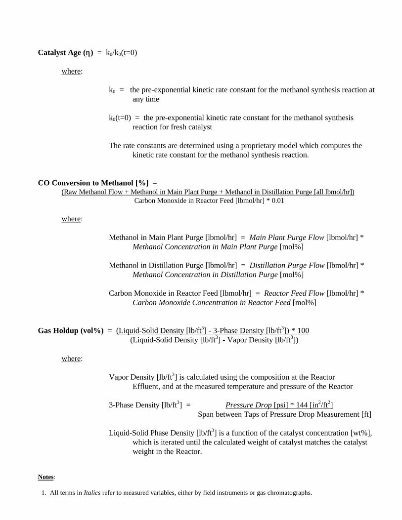
APPENDIX L Page 1 of 4
Notes:
1. All terms in Italics refer to measured variables, either by field instruments or gas chromatographs.
Catalyst Age (ηη) = k0/k0(t=0)
where:
k0 = the pre-exponential kinetic rate constant for the methanol synthesis reaction atany time
k0(t=0) = the pre-exponential kinetic rate constant for the methanol synthesisreaction for fresh catalyst
The rate constants are determined using a proprietary model which computes thekinetic rate constant for the methanol synthesis reaction.
CO Conversion to Methanol [%] =(Raw Methanol Flow + Methanol in Main Plant Purge + Methanol in Distillation Purge [all lbmol/hr])
Carbon Monoxide in Reactor Feed [lbmol/hr] * 0.01
where:
Methanol in Main Plant Purge [lbmol/hr] = Main Plant Purge Flow [lbmol/hr] *Methanol Concentration in Main Plant Purge [mol%]
Methanol in Distillation Purge [lbmol/hr] = Distillation Purge Flow [lbmol/hr] *Methanol Concentration in Distillation Purge [mol%]
Carbon Monoxide in Reactor Feed [lbmol/hr] = Reactor Feed Flow [lbmol/hr] *Carbon Monoxide Concentration in Reactor Feed [mol%]
Gas Holdup (vol%) = (Liquid-Solid Density [lb/ft3] - 3-Phase Density [lb/ft3]) * 100 (Liquid-Solid Density [lb/ft3] - Vapor Density [lb/ft3])
where:
Vapor Density [lb/ft3] is calculated using the composition at the ReactorEffluent, and at the measured temperature and pressure of the Reactor
3-Phase Density [lb/ft3] = Pressure Drop [psi] * 144 [in2/ft2] Span between Taps of Pressure Drop Measurement [ft]
Liquid-Solid Phase Density [lb/ft3] is a function of the catalyst concentration [wt%],which is iterated until the calculated weight of catalyst matches the catalystweight in the Reactor.

APPENDIX L Page 2 of 4
Notes:
1. All terms in Italics refer to measured variables, either by field instruments or gas chromatographs.
Gassed Slurry Volume [ft3] = Reactor Cylindrical Volume [ft3] + Reactor Head Volume [ft3]
where: Reactor Cylindrical Volume [ft3] = A [ft2] * Cylindrical Height [ft]
A [ft2] = Π * (Reactor ID [ft])2 * (Fraction Open Area) 4
Reactor ID = Reactor Inside Diameter = 7.5 ft
Fraction Open Area = 0.9652 (3.48% of the cross-sectional area of the Reactor isoccupied by the tubes of the internal heat exchanger)
Cylindrical Height [ft] = Gassed Slurry Height [ft] - (Reactor ID [ft]) 4
Note: The term “(Reactor ID)/4” is the depth of the bottom head of the Reactor.
Reactor Head Volume [ft3] = Π * (Reactor ID [ft])3 - 8 [ft3] 24
Note: 8 cubic feet is subtracted from the Reactor Head Volume to accountfor the displacement of the gas sparger and the header piping for theinternal heat exchanger.
Inlet Superficial Velocity [ft/s] = Reactor Feed Flow [lbmol/hr] * V [ft3/lbmol] 3,600 [s/hr] * A [ft2]
where: V [ft3/lbmol] = 10.73 * (Reactor Temperature [°F] + 459.67) (Reactor Pressure [psig] + 14.1)
A [ft2] = Π * (Reactor ID [ft])2 * (Fraction Open Area) 4
Reactor ID = Reactor Inside Diameter = 7.5 ft
Fraction Open Area = 0.9652 (3.48% of the cross-sectional area of the Reactor isoccupied by the tubes of the internal heat exchanger)
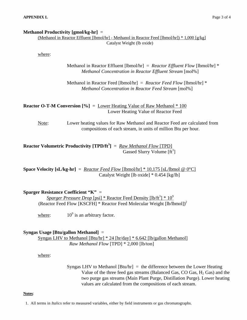
APPENDIX L Page 3 of 4
Notes:
1. All terms in Italics refer to measured variables, either by field instruments or gas chromatographs.
Methanol Productivity [gmol/kg-hr] =(Methanol in Reactor Effluent [lbmol/hr] - Methanol in Reactor Feed [lbmol/hr]) * 1,000 [g/kg] Catalyst Weight (lb oxide)
where:
Methanol in Reactor Effluent [lbmol/hr] = Reactor Effluent Flow [lbmol/hr] *Methanol Concentration in Reactor Effluent Stream [mol%]
Methanol in Reactor Feed [lbmol/hr] = Reactor Feed Flow [lbmol/hr] *Methanol Concentration in Reactor Feed Stream [mol%]
Reactor O-T-M Conversion [%] = Lower Heating Value of Raw Methanol * 100 Lower Heating Value of Reactor Feed
Note: Lower heating values for Raw Methanol and Reactor Feed are calculated fromcompositions of each stream, in units of million Btu per hour.
Reactor Volumetric Productivity [TPD/ft3] = Raw Methanol Flow [TPD] Gassed Slurry Volume [ft3]
Space Velocity [sL/kg-hr] = Reactor Feed Flow [lbmol/hr] * 10,175 [sL/lbmol @ 0°C] Catalyst Weight [lb oxide] * 0.454 [kg/lb]
Sparger Resistance Coefficient “K” = Sparger Pressure Drop [psi] * Reactor Feed Density [lb/ft3] * 109
(Reactor Feed Flow [KSCFH] * Reactor Feed Molecular Weight [lb/lbmol])2
where: 109 is an arbitrary factor.
Syngas Usage [Btu/gallon Methanol] =Syngas LHV to Methanol [Btu/hr] * 24 [hr/day] * 6.642 [lb/gallon Methanol] Raw Methanol Flow [TPD] * 2,000 [lb/ton]
where:
Syngas LHV to Methanol [Btu/hr] = the difference between the Lower HeatingValue of the three feed gas streams (Balanced Gas, CO Gas, H2 Gas) and thetwo purge gas streams (Main Plant Purge, Distillation Purge). Lower heatingvalues are calculated from the compositions of each stream.

APPENDIX L Page 4 of 4
Notes:
1. All terms in Italics refer to measured variables, either by field instruments or gas chromatographs.
Syngas Utilization [SCF/lb Methanol] =(Balanced Gas Flow [SCFH] + CO Gas Flow [SCFH]) * 24 [hr/day] Raw Methanol Flow [TPD] * 2,000 [lb/ton]

TPR12C.DOC Apr. - Jun. 97 Page 44 of 46 06/09/98
APPENDIX M - TASK 3.6 - INTERIM PROJECT REVIEW MEETING(29 & 30 April 1997)
TPR12C.DOC Apr. - Jun. 97 Page 45 of 46 06/09/98
APPENDIX N - TASK 3.6 - MILESTONE SCHEDULE STATUS AND COSTMANAGEMENT REPORTS

TPR12C.DOC Apr. - Jun. 97 Page 46 of 46 06/09/98
APPENDIX O - PRESS RELEASE (21 MAY 1997) AND PRESS COVERAGE