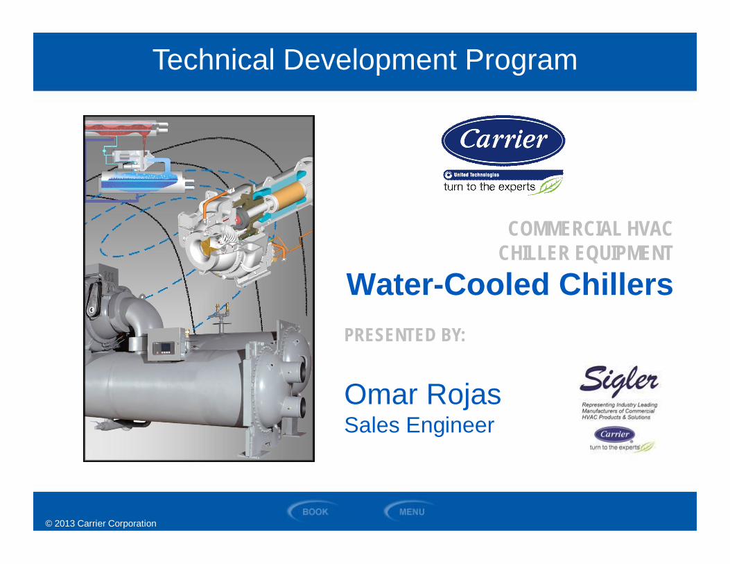
commercial hvac chiller equipment water-cooled...
TRANSCRIPT
© 2013 Carrier Corporation
COMMERCIAL HVACCHILLER EQUIPMENT
Water-Cooled ChillersPRESENTED BY:
Omar RojasSales Engineer
Technical Development Program
© 2013 Carrier Corporation
MenuSection 1 Introduction
Section 2 Basic Refrigeration Cycle
Section 3 Chiller Components
Section 12 Summary
Section 4 Chiller Controls
Section 5 Screw Compressor Operational Details
Section 6 Centrifugal Compressor Operational Details
Section 7 Capacity Control Methods
Section 8 Refrigerant Related Topics
Section 9 Heat Transfer
Section 11 Selection Criteria
Section 10 Codes and Standards
© 2013 Carrier Corporation
SECTION 1
Introduction
WATER-COOLED CHILLERS

© 2013 Carrier Corporation
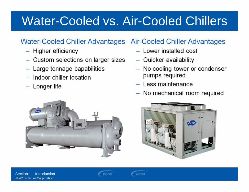
• Compare the advantages of water-cooledversus air-cooled chillers
• Identify and diagram the different componentsof a basic refrigeration cycle as it applies to awater-cooled chiller
• Compare and describe the differences amongscroll, reciprocating, centrifugal, and screwwater-cooled chillers and their applications
• Discuss the differences in construction ofwater-cooled chillers of various sizes
• Identify the codes and standardsthat apply to water-cooled chillers
• Understand the typical inputs requiredto select a water-cooled chiller
Section 1 – Introduction
Objectives
© 2013 Carrier Corporation
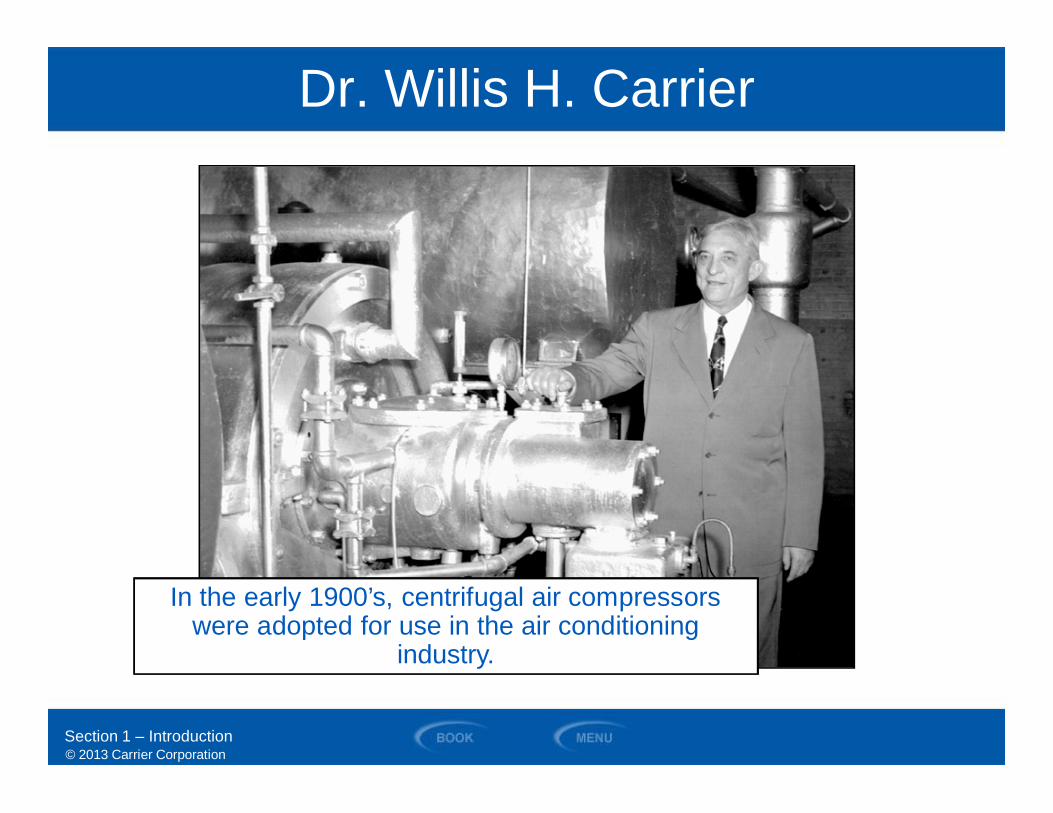
Dr. Willis H. Carrier
In the early 1900’s, centrifugal air compressorswere adopted for use in the air conditioning
industry.
Section 1 – Introduction

© 2013 Carrier Corporation
Early Centrifugal Chiller
Section 1 – Introduction
© 2013 Carrier Corporation
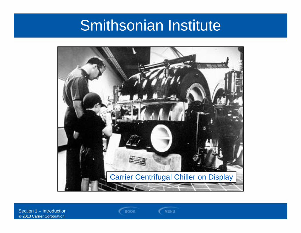
Smithsonian Institute
Carrier Centrifugal Chiller on Display
Section 1 – Introduction
© 2013 Carrier Corporation
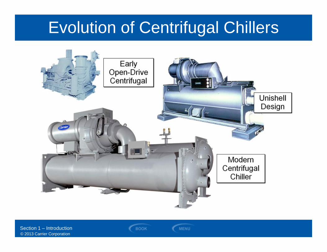
Evolution of Centrifugal Chillers
Section 1 – Introduction
© 2013 Carrier Corporation
Water-Cooled vs. Air-Cooled Chillers
Section 1 – Introduction
© 2013 Carrier Corporation
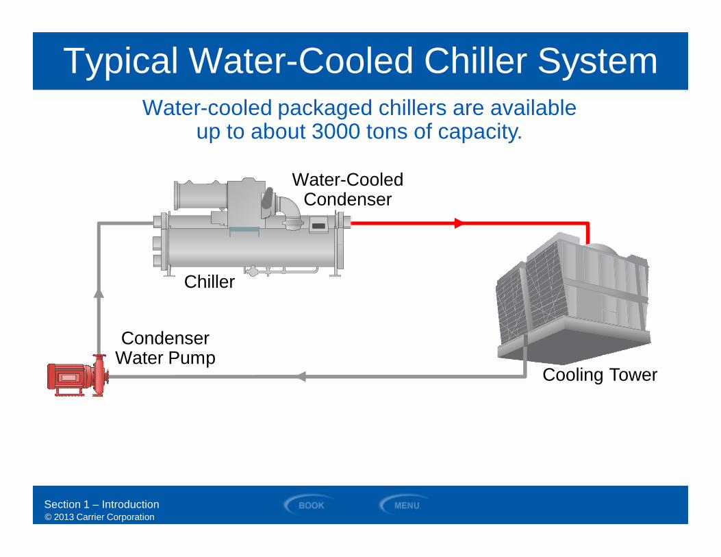
Water-cooled packaged chillers are availableup to about 3000 tons of capacity.
Typical Water-Cooled Chiller System
Water-CooledCondenser
Chiller
Cooling Tower
CondenserWater Pump
Section 1 – Introduction
© 2013 Carrier Corporation
SECTION 2
Basic Refrigeration Cycle
WATER-COOLED CHILLERS
© 2013 Carrier Corporation
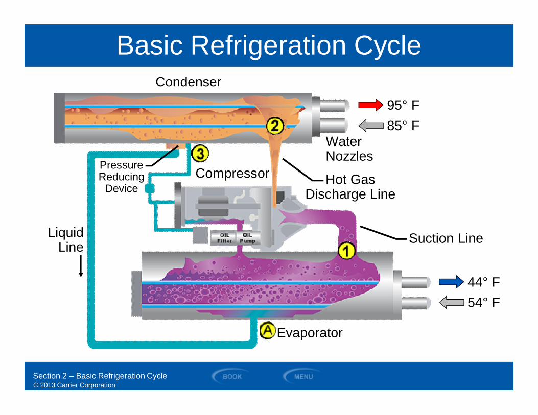
Evaporator
Condenser
Compressor
WaterNozzles
PressureReducing
Device
95° F85° F
44° F54° F
LiquidLine
Hot GasDischarge Line
Suction Line
Basic Refrigeration Cycle
Section 2 – Basic Refrigeration Cycle
© 2013 Carrier Corporation
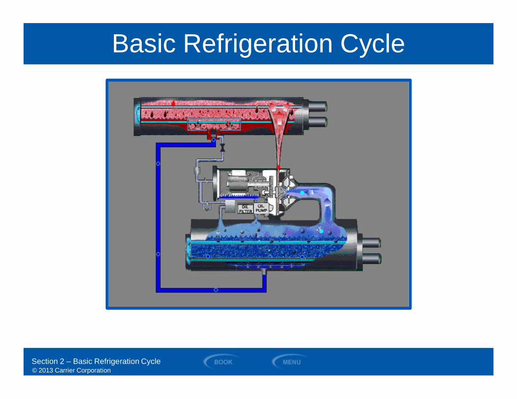
Basic Refrigeration Cycle
Section 2 – Basic Refrigeration Cycle

© 2013 Carrier Corporation
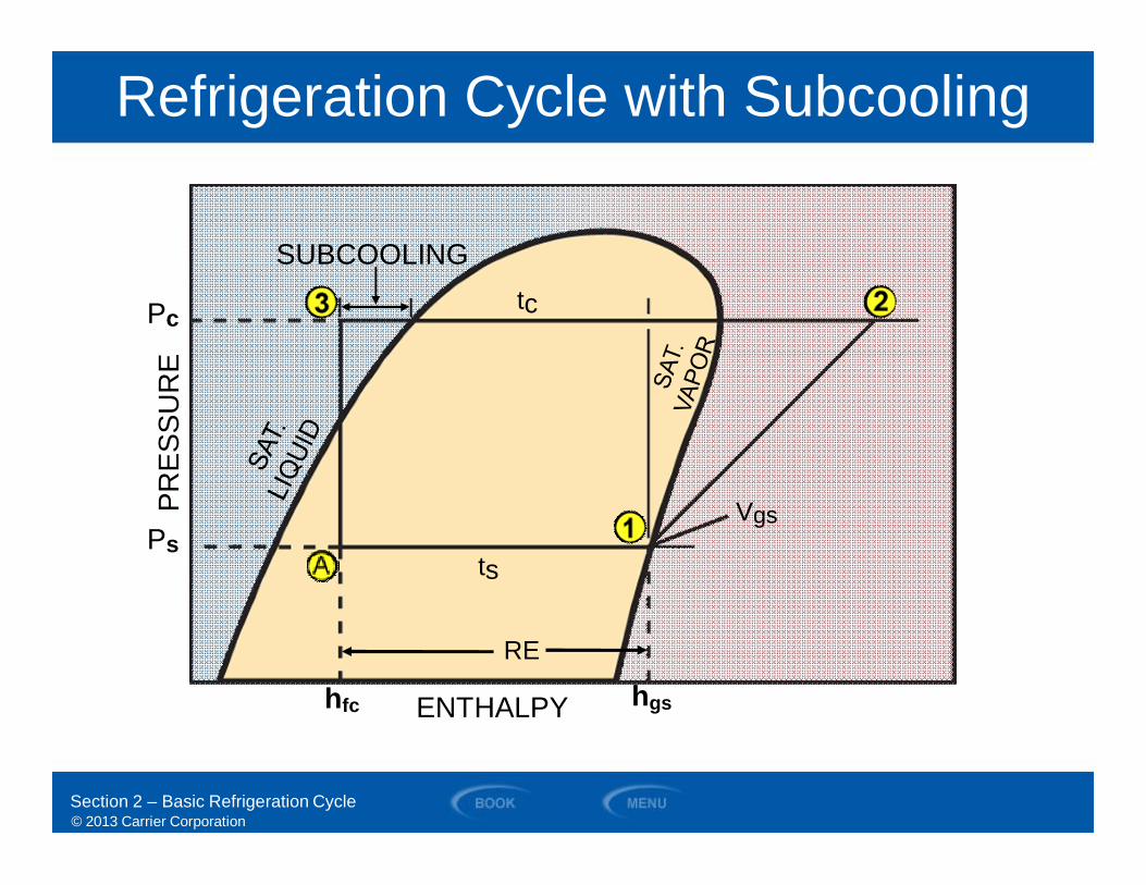
Pressure-Enthalpy DiagramRefrigeration Cycle
LIFT
Section 2 – Basic Refrigeration Cycle
Saturated Condensing
Saturated Suction
PRES
SUR
E
RE
Pc
Ps
ENTHALPY
© 2013 Carrier Corporation
Refrigeration Cycle with Subcooling
SUBCOOLING
ts
tc
hfc hgs
PRES
SUR
E
ENTHALPY
Pc
PsVgs
RE
Section 2 – Basic Refrigeration Cycle
© 2013 Carrier Corporation
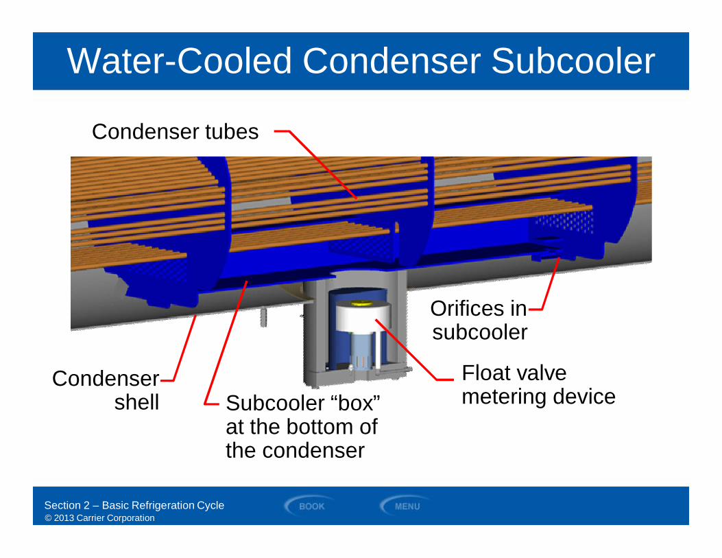
Water-Cooled Condenser Subcooler
Subcooler “box”at the bottom ofthe condenser
Float valvemetering device
Orifices insubcooler
Condenser tubes
Condensershell
Section 2 – Basic Refrigeration Cycle
© 2013 Carrier Corporation
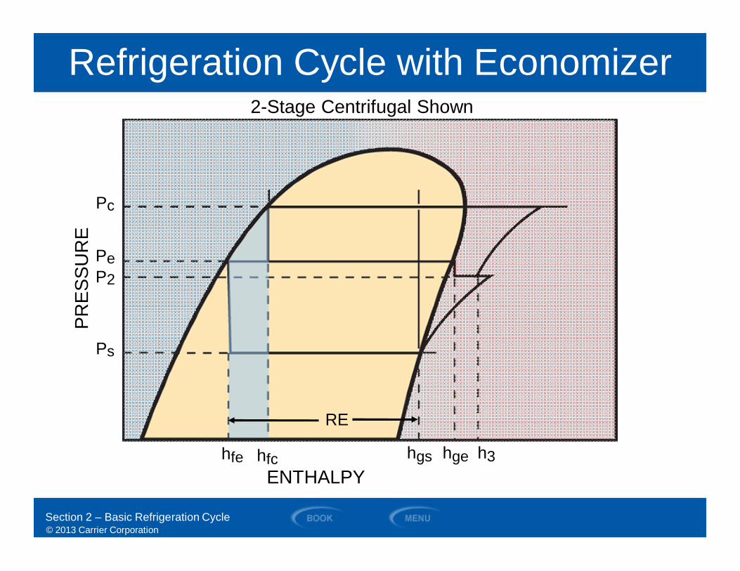
Refrigeration Cycle with Economizer2-Stage Centrifugal Shown
RE
Pc
Ps
hfchfe hgs hge h3
P2Pe
PRES
SUR
E
ENTHALPY
Section 2 – Basic Refrigeration Cycle
© 2013 Carrier Corporation
SECTION 3
Chiller Components
WATER-COOLED CHILLERS
© 2013 Carrier Corporation
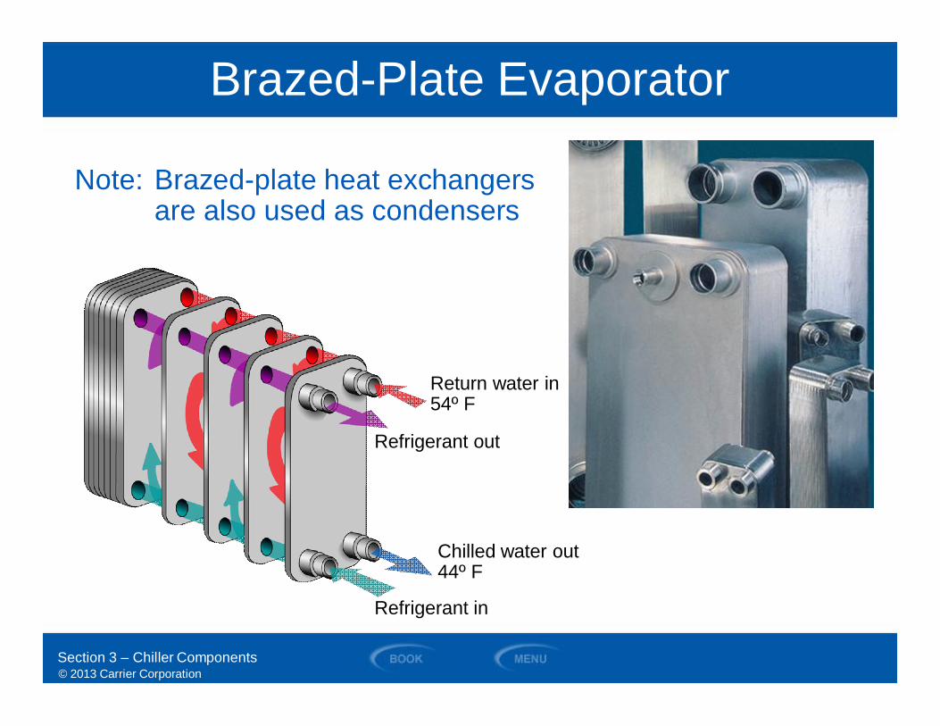
Brazed-Plate Evaporator
Section 3 – Chiller Components
Note: Brazed-plate heat exchangersare also used as condensers
Return water in54º F
Refrigerant out
Chilled water out44º F
Refrigerant in
© 2013 Carrier Corporation
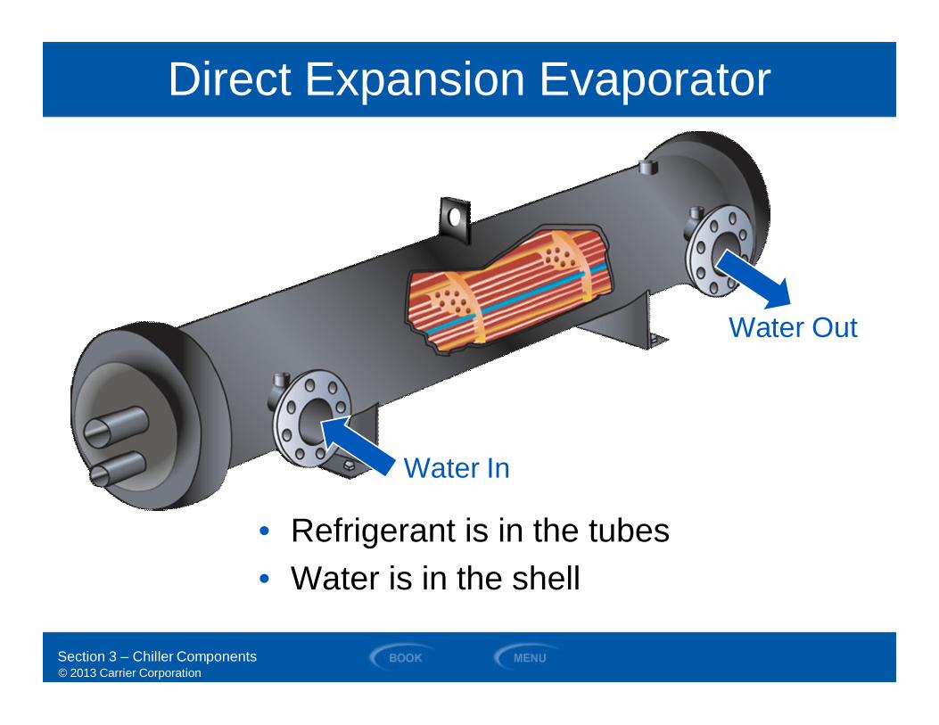
Direct Expansion Evaporator
Water Out
Water In
• Refrigerant is in the tubes• Water is in the shell
Section 3 – Chiller Components
© 2013 Carrier Corporation
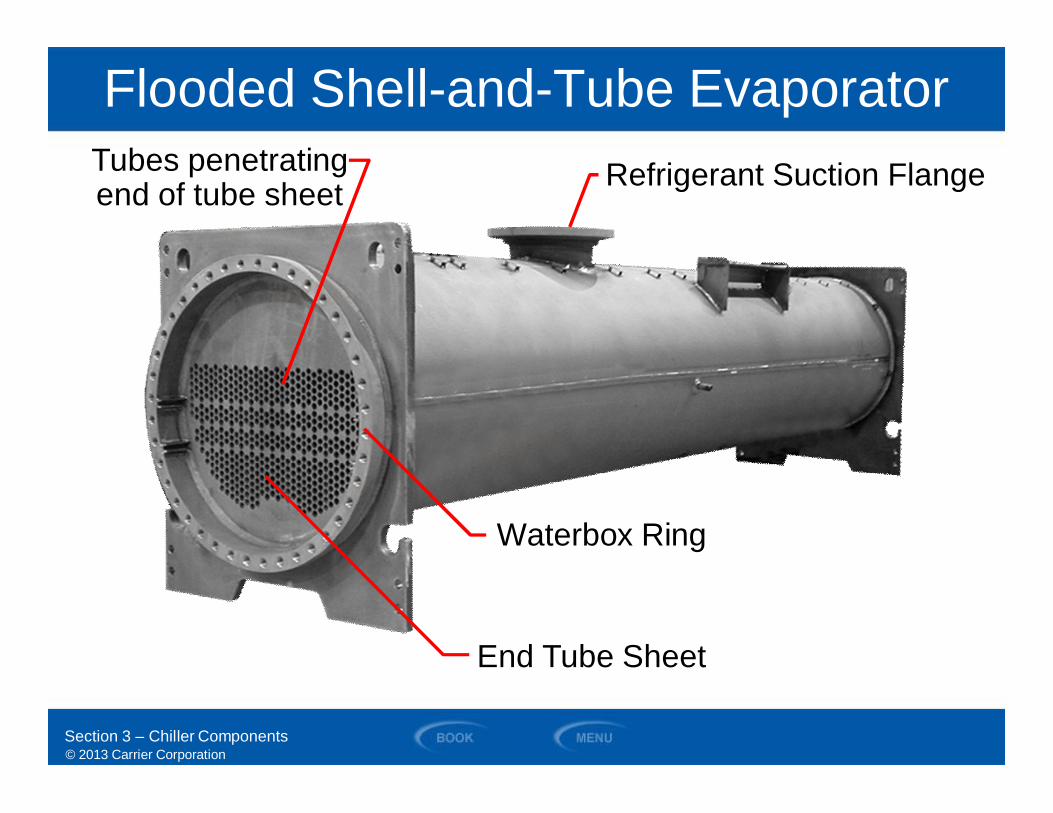
Flooded Shell-and-Tube Evaporator
End Tube Sheet
Refrigerant Suction Flange
Waterbox Ring
Tubes penetratingend of tube sheet
Section 3 – Chiller Components
© 2013 Carrier Corporation
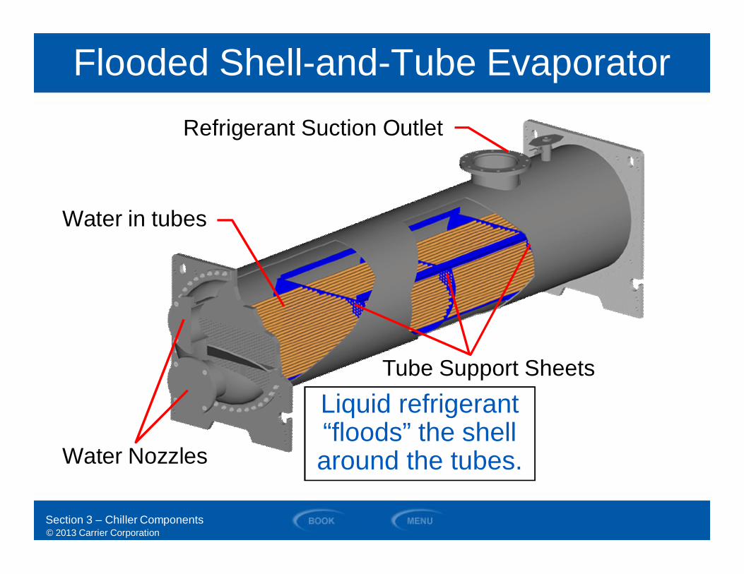
Flooded Shell-and-Tube Evaporator
Tube Support Sheets
Water in tubes
Water Nozzles
Refrigerant Suction Outlet
Liquid refrigerant“floods” the shellaround the tubes.
Section 3 – Chiller Components
© 2013 Carrier Corporation
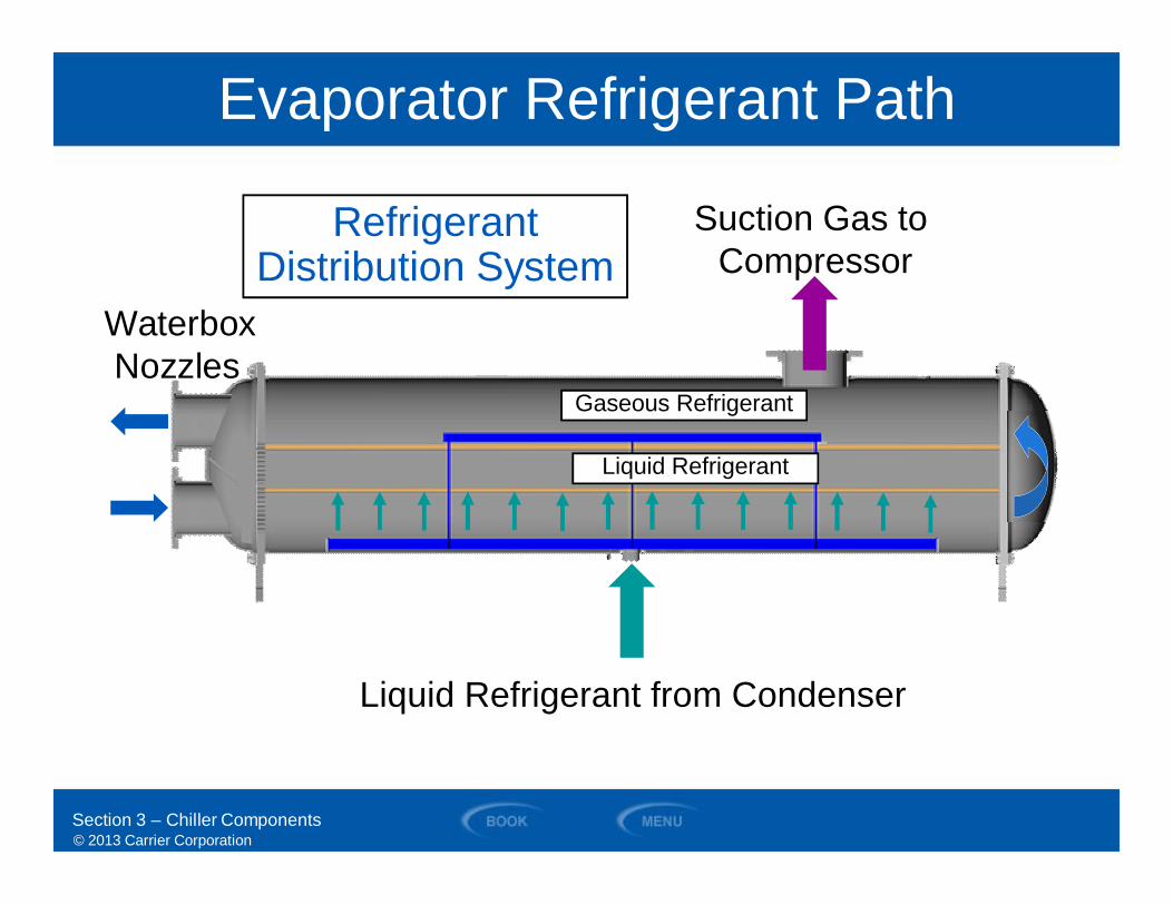
Evaporator Refrigerant Path
Liquid Refrigerant from Condenser
Suction Gas toCompressor
WaterboxNozzles
Gaseous RefrigerantGaseous Refrigerant
Liquid RefrigerantLiquid Refrigerant
RefrigerantDistribution System
Section 3 – Chiller Components
© 2013 Carrier Corporation
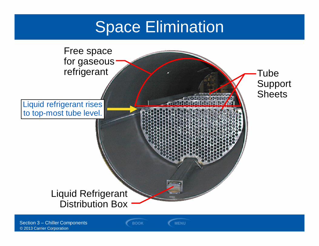
Space Elimination
Liquid RefrigerantDistribution Box
Free spacefor gaseousrefrigerant Tube
SupportSheets
Liquid refrigerant risesLiquid refrigerant risesto top-most tube level.
Section 3 – Chiller Components

© 2013 Carrier Corporation
End Tube Support Sheet
Double Grooves
Section 3 – Chiller Components
© 2013 Carrier CorporationSection 3 – Chiller Components
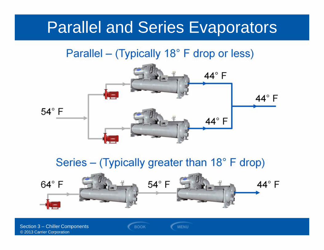
Parallel and Series Evaporators
© 2013 Carrier Corporation
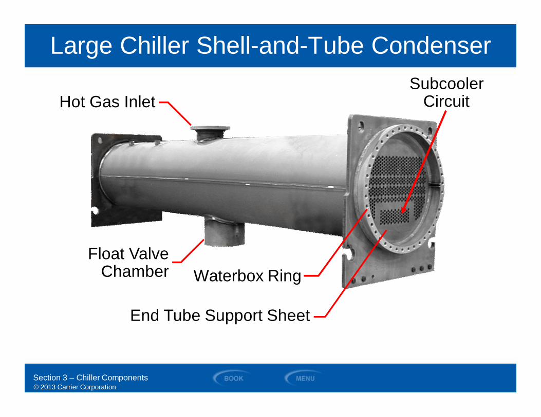
End Tube Support Sheet
Waterbox RingFloat Valve
Chamber
Hot Gas InletSubcooler
Circuit
Large Chiller Shell-and-Tube Condenser
Section 3 – Chiller Components
© 2013 Carrier Corporation
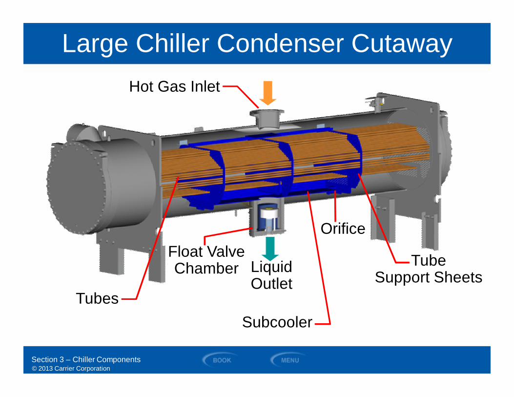
Float ValveChamber
Orifice
Hot Gas Inlet
Tubes
TubeSupport Sheets
Subcooler
Large Chiller Condenser Cutaway
Section 3 – Chiller Components
LiquidOutlet
© 2013 Carrier Corporation
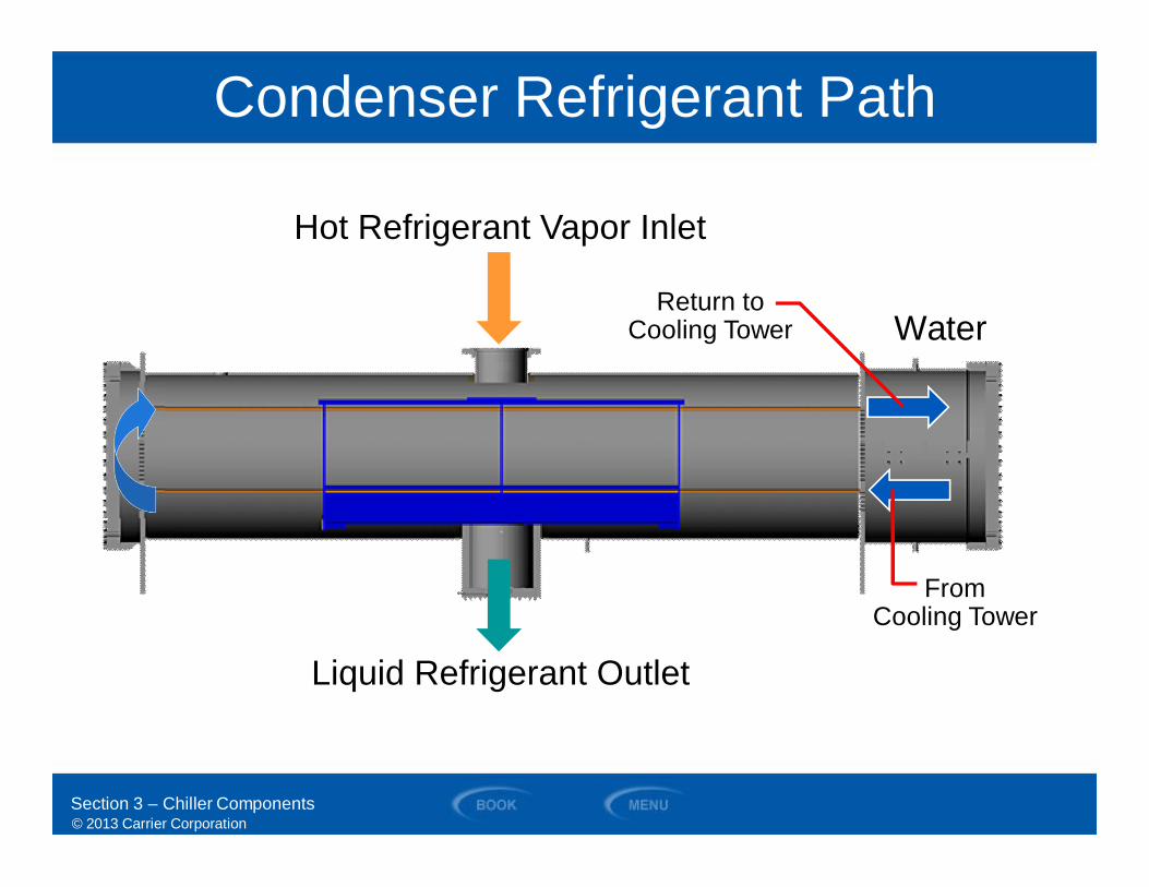
Condenser Refrigerant Path
Hot Refrigerant Vapor Inlet
Water
Liquid Refrigerant Outlet
Return toCooling Tower
FromCooling Tower
Section 3 – Chiller Components
© 2013 Carrier Corporation
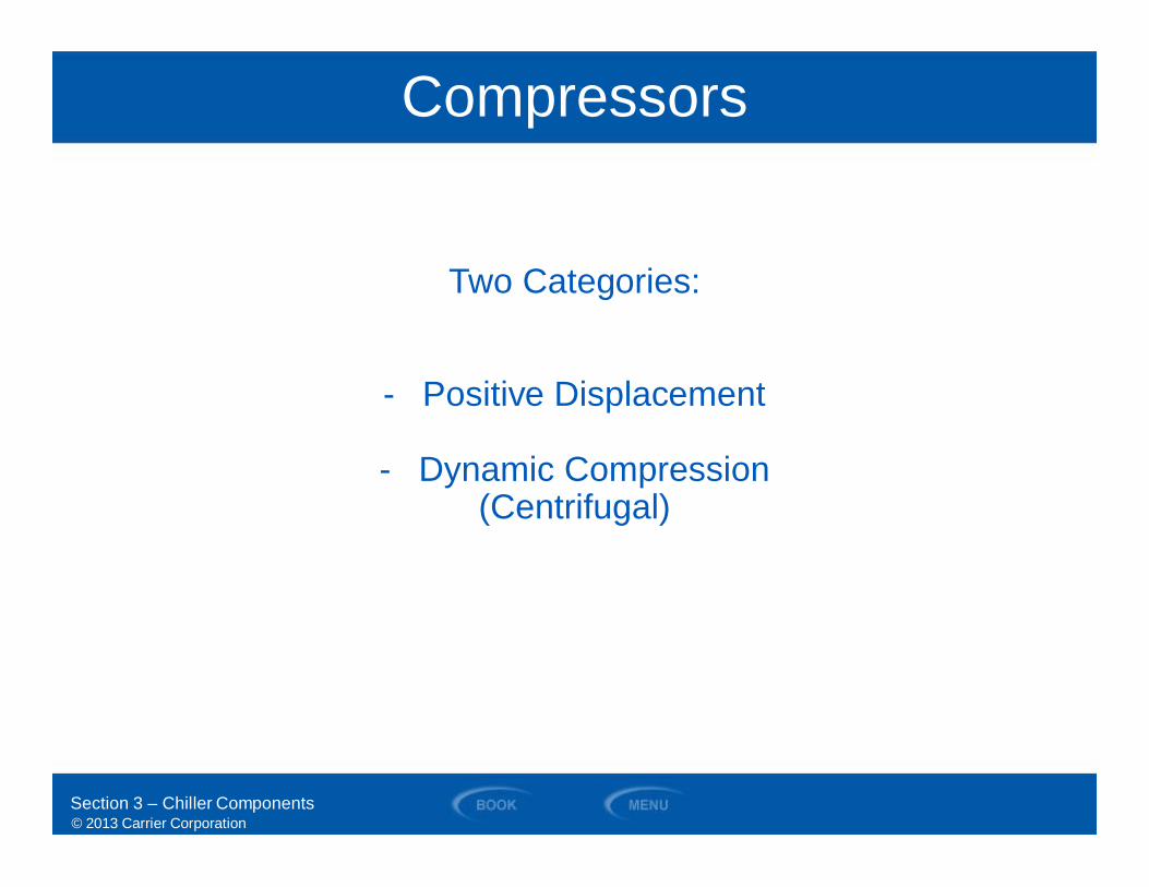
Compressors
Two Categories:
- Positive Displacement
- Dynamic Compression(Centrifugal)
Section 3 – Chiller Components
© 2013 Carrier Corporation
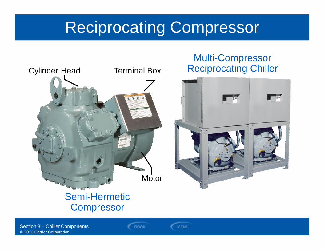
Semi-HermeticCompressor
Reciprocating Compressor
Cylinder Head Terminal Box
Motor
Multi-CompressorReciprocating Chiller
Section 3 – Chiller Components
© 2013 Carrier Corporation
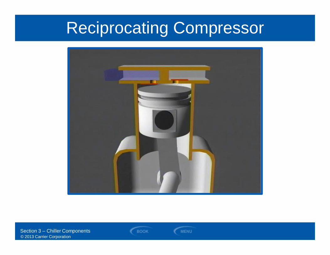
Reciprocating Compressor
Section 3 – Chiller Components

© 2013 Carrier Corporation
Scroll Compressor
HermeticShell
SuctionInlet
HermeticMotor
Hot GasDischarge
Electrical TerminalConnection
OrbitingScrolls
Pressure Relief
Section 3 – Chiller Components
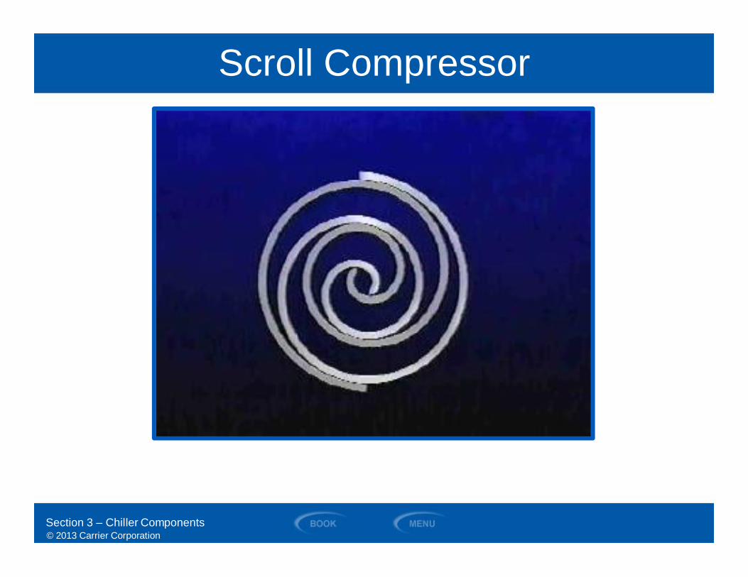
© 2013 Carrier Corporation
Scroll Compressor
Section 3 – Chiller Components
© 2013 Carrier Corporation
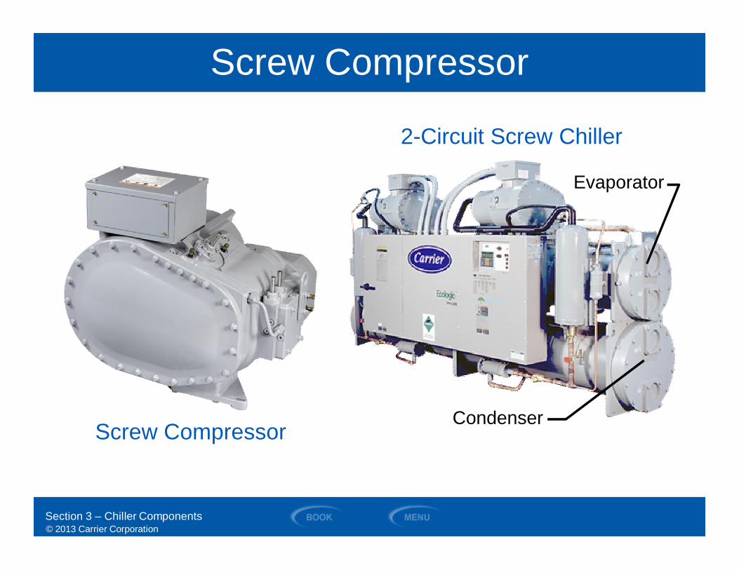
Screw Compressor
Screw Compressor
Evaporator
Condenser
2-Circuit Screw Chiller
Section 3 – Chiller Components
© 2013 Carrier Corporation
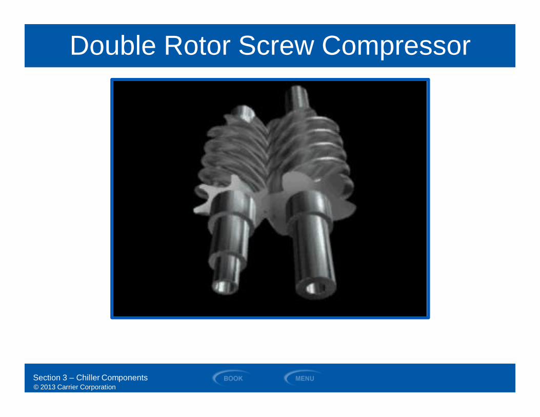
Double Rotor Screw Compressor
Section 3 – Chiller Components
© 2013 Carrier Corporation
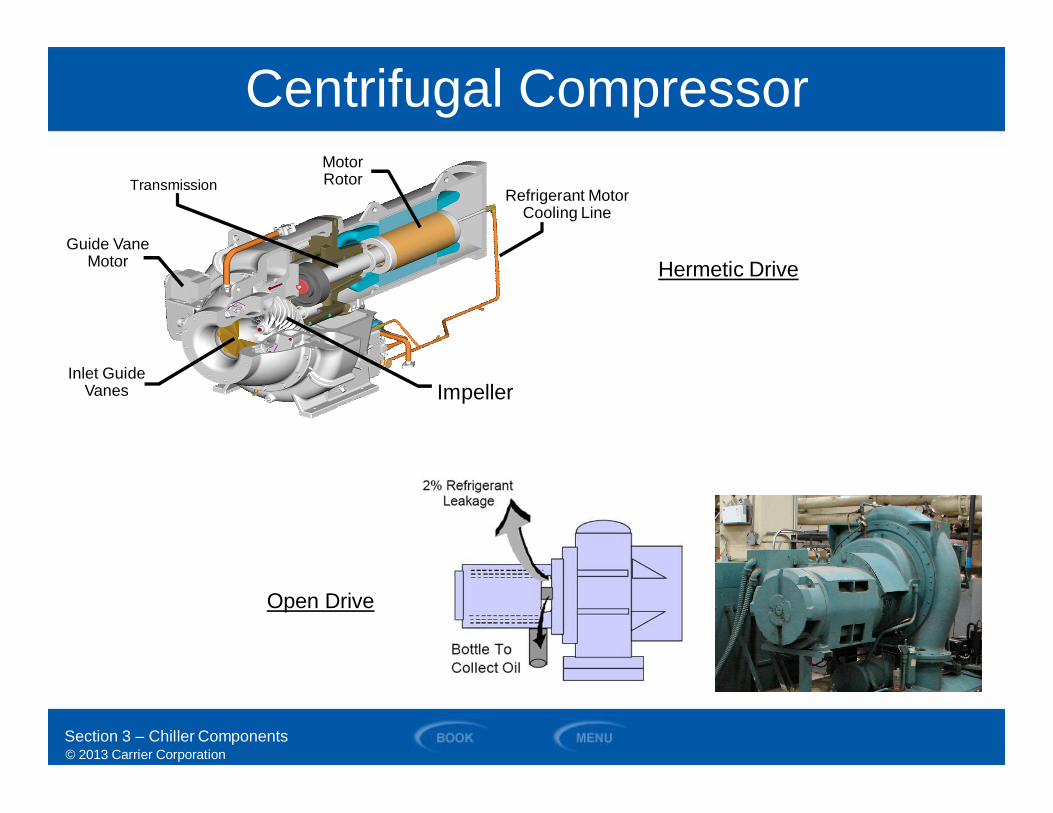
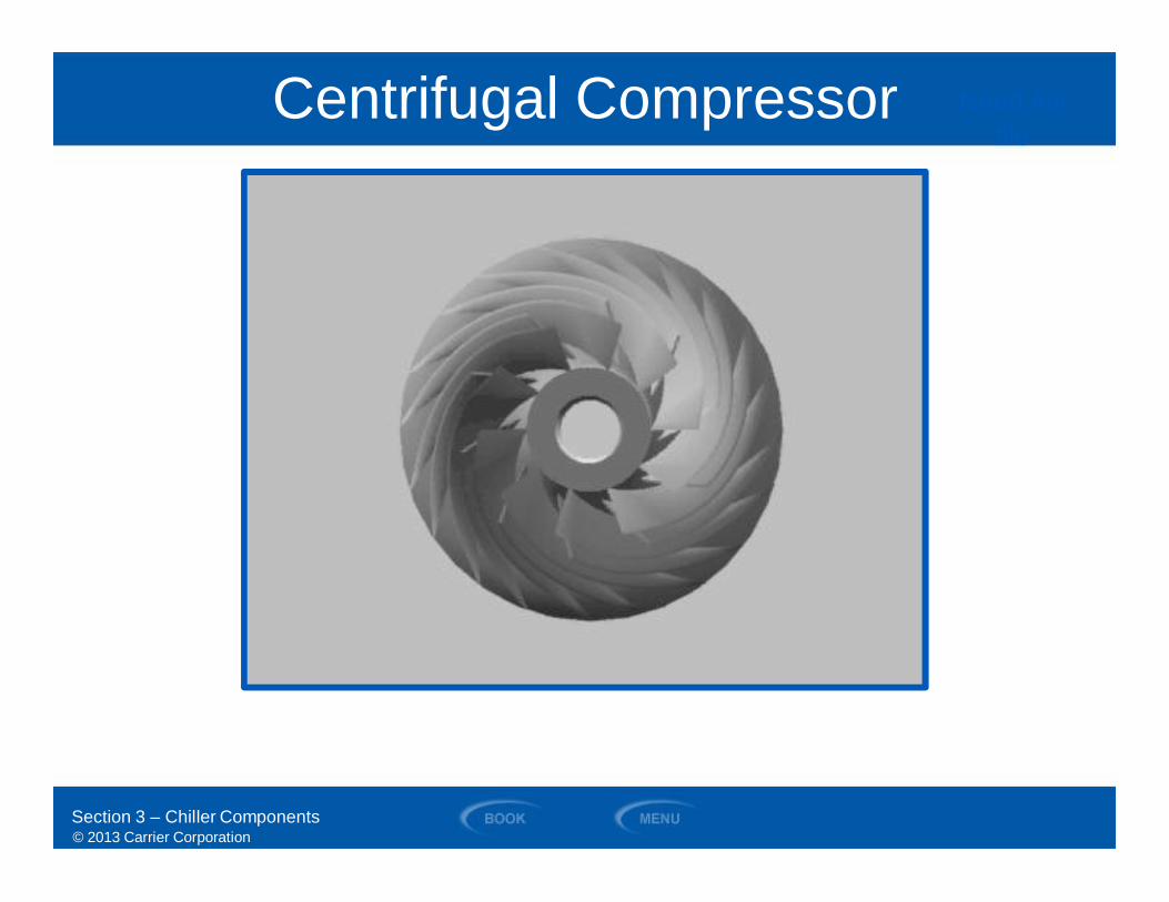
Centrifugal Compressor
Inlet GuideVanes
Transmission
Impeller
Guide VaneMotor
Refrigerant MotorCooling Line
MotorRotor
Section 3 – Chiller Components
Hermetic Drive
Open Drive
© 2013 Carrier Corporation
Centrifugal Compressor Need Avifile
Section 3 – Chiller Components

© 2013 Carrier Corporation
Hermetic Centrifugal CompressorRefrigerant Cooling Transmission
InletGuideVanes
Impeller
High SpeedShaft
HermeticHousing
Oil Filter
Electric MotorRotor
Low SpeedShaft
Oil Pump
Section 3 – Chiller Components
© 2013 Carrier Corporation
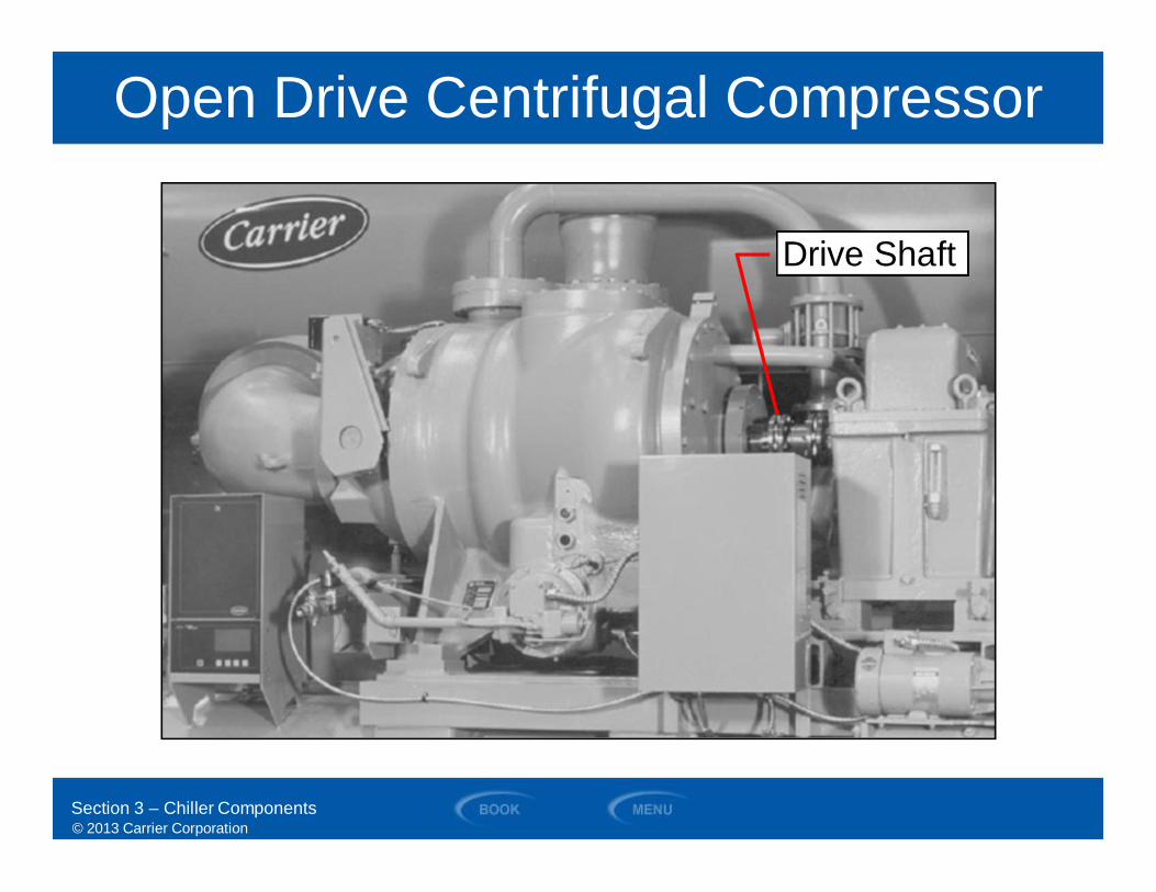
Open Drive Centrifugal Compressor
Section 3 – Chiller Components
Drive Shaft
© 2013 Carrier Corporation
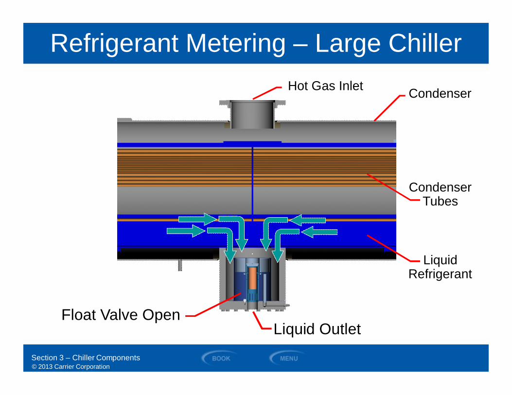
Refrigerant Metering – Large Chiller
Float Valve Open
Hot Gas Inlet Condenser
CondenserTubes
LiquidRefrigerant
Section 3 – Chiller Components
Liquid Outlet
© 2013 Carrier Corporation
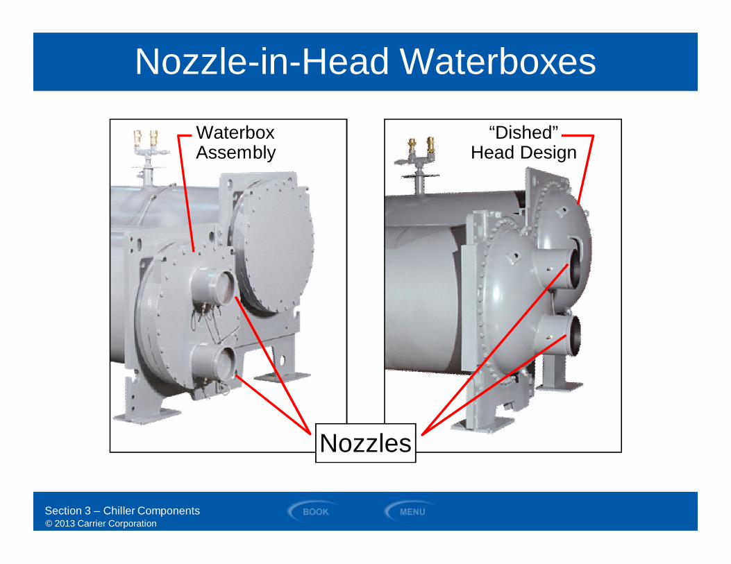
Nozzle-in-Head Waterboxes
Nozzles
WaterboxAssembly
“Dished”Head Design
Section 3 – Chiller Components
© 2013 Carrier Corporation
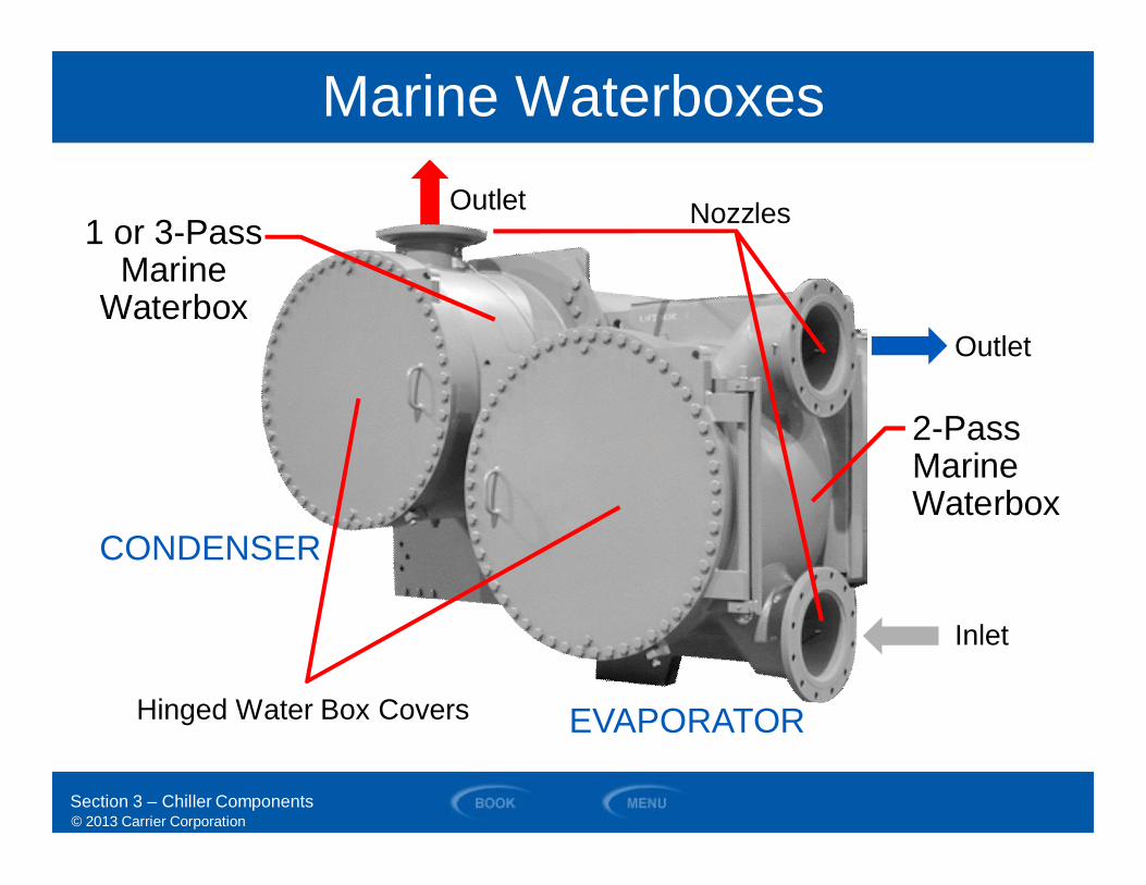
Marine Waterboxes
Nozzles
Hinged Water Box Covers
1 or 3-PassMarine
Waterbox
EVAPORATOR
CONDENSER
2-PassMarineWaterbox
Outlet
Inlet
Section 3 – Chiller Components
Outlet
© 2013 Carrier Corporation
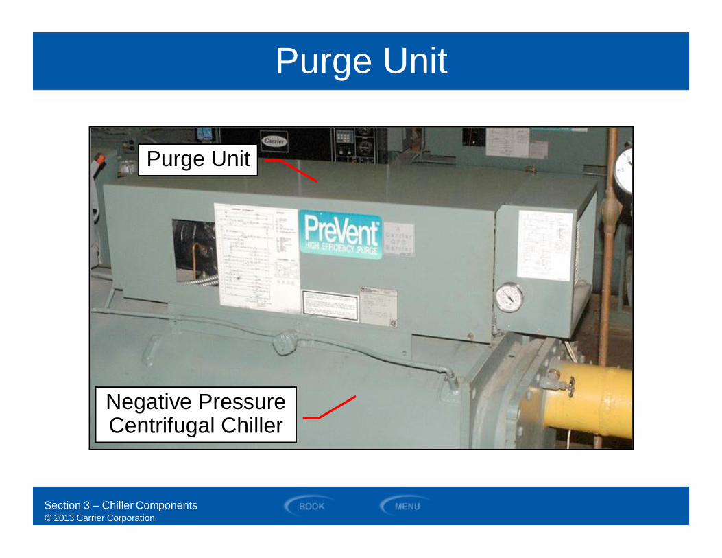
Purge Unit
Purge Unit
Negative PressureCentrifugal Chiller
Section 3 – Chiller Components
© 2013 Carrier Corporation
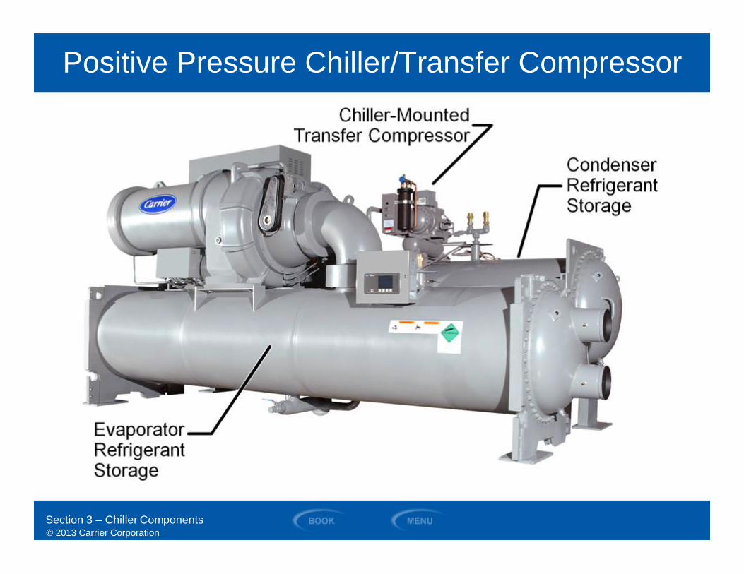
Positive Pressure Chiller/Transfer Compressor
Section 3 – Chiller Components
© 2013 Carrier Corporation
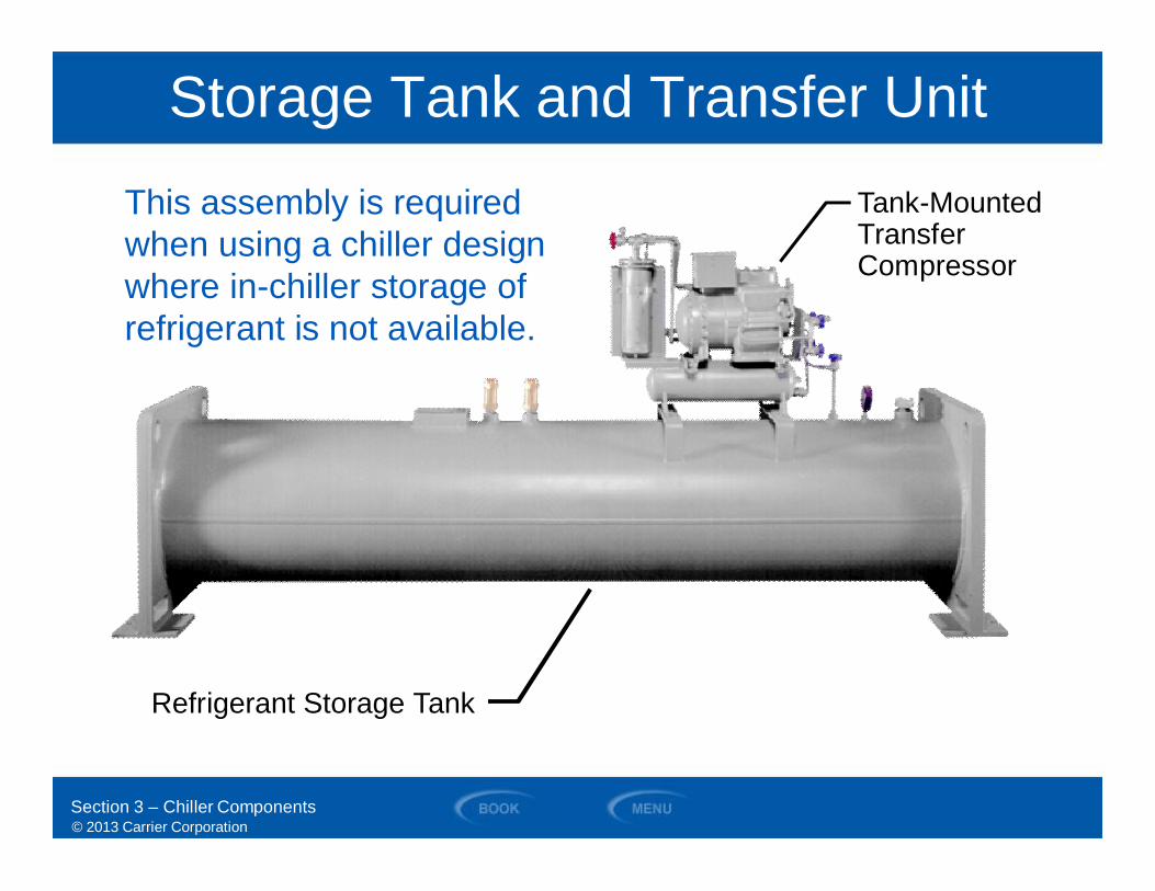
Storage Tank and Transfer UnitTank-MountedTransferCompressor
Refrigerant Storage Tank
This assembly is requiredwhen using a chiller designwhere in-chiller storage ofrefrigerant is not available.
Section 3 – Chiller Components
© 2013 Carrier Corporation
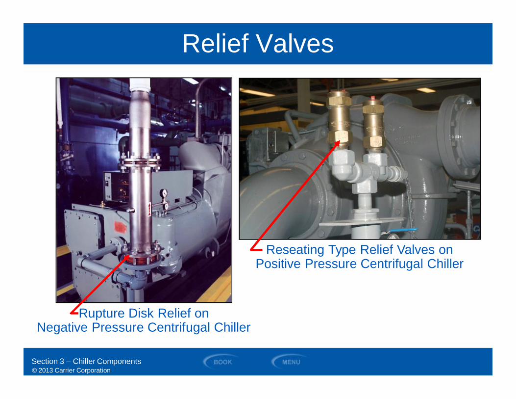
Relief Valves
Rupture Disk Relief onNegative Pressure Centrifugal Chiller
Reseating Type Relief Valves onPositive Pressure Centrifugal Chiller
Section 3 – Chiller Components
© 2013 Carrier Corporation
SECTION 4
Chiller Controls
WATER-COOLED CHILLERS
© 2013 Carrier Corporation
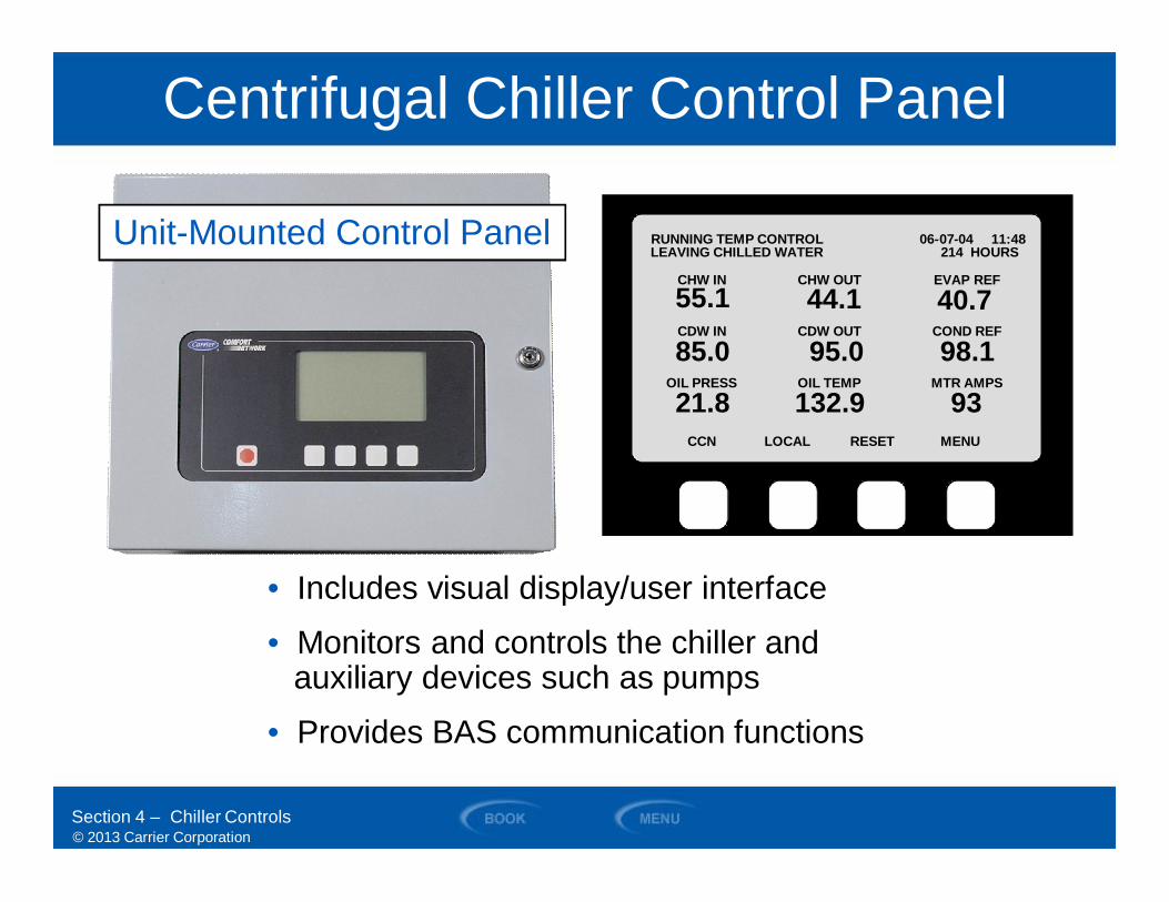
Centrifugal Chiller Control Panel
RUNNING TEMP CONTROLLEAVING CHILLED WATER
06-07-04 11:48214 HOURS
CCN LOCAL RESET MENU
CHW IN55.1
CHW OUT
44.1EVAP REF
40.7CDW IN
85.0CDW OUT
95.0COND REF
98.1OIL PRESS
21.8OIL TEMP
132.9MTR AMPS
93
Section 4 – Chiller Controls
Unit-Mounted Control Panel
• Includes visual display/user interface
• Monitors and controls the chiller andauxiliary devices such as pumps
• Provides BAS communication functions
© 2013 Carrier Corporation
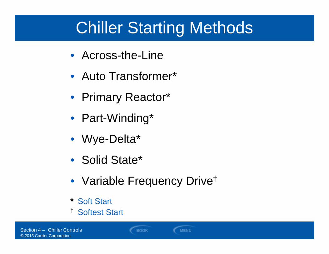
Chiller Starting Methods• Across-the-Line
• Auto Transformer*
• Primary Reactor*
• Part-Winding*
• Wye-Delta*
• Solid State*
• Variable Frequency Drive†
Section 4 – Chiller Controls
* Soft Start† Softest Start
© 2013 Carrier Corporation
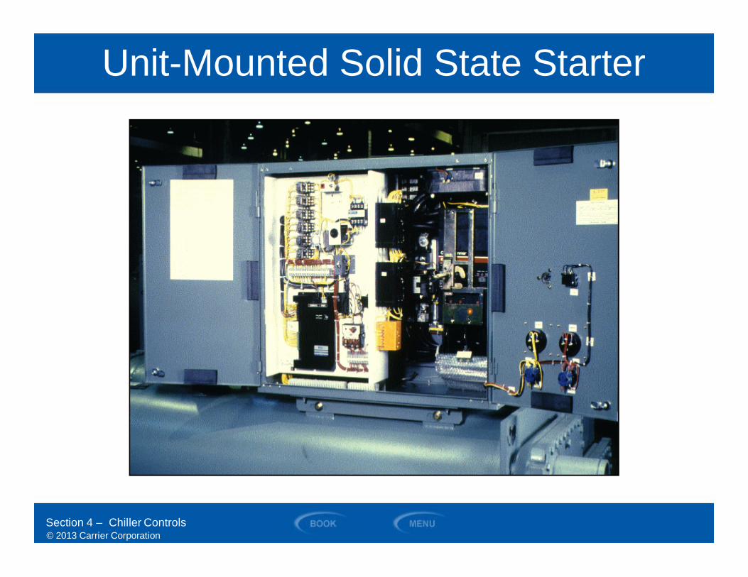
Unit-Mounted Solid State Starter
Section 4 – Chiller Controls
© 2013 Carrier Corporation
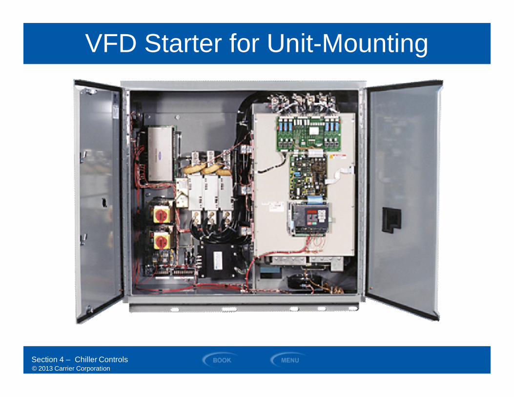
VFD Starter for Unit-Mounting
Section 4 – Chiller Controls
© 2013 Carrier Corporation
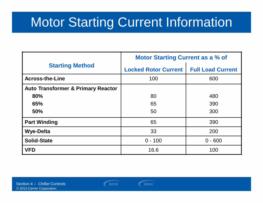
Motor Starting Current Information
Section 4 – Chiller Controls
Starting MethodMotor Starting Current as a % of
Locked Rotor Current Full Load CurrentAcross-the-Line 100 600
Auto Transformer & Primary Reactor80%65%50%
806550
480390300
Part Winding 65 390
Wye-Delta 33 200
Solid-State 0 - 100 0 - 600
VFD 16.6 100
© 2013 Carrier Corporation
SECTION 5
Screw CompressorOperational Details
WATER-COOLED CHILLERS
© 2013 Carrier Corporation
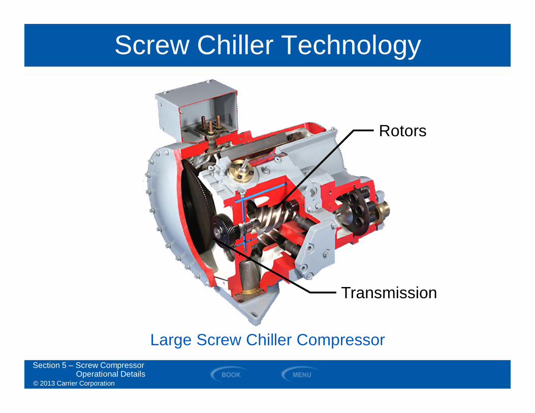
Screw Chiller Technology
Section 5 – Screw CompressorOperational Details
Large Screw Chiller Compressor
Transmission
Rotors
© 2013 Carrier Corporation
SECTION 6
Centrifugal CompressorOperational Details
WATER-COOLED CHILLERS

© 2013 Carrier Corporation
FORCE
BALL
DIAMETER
GASMOLECULE
FORCE
LENGTH
STRING
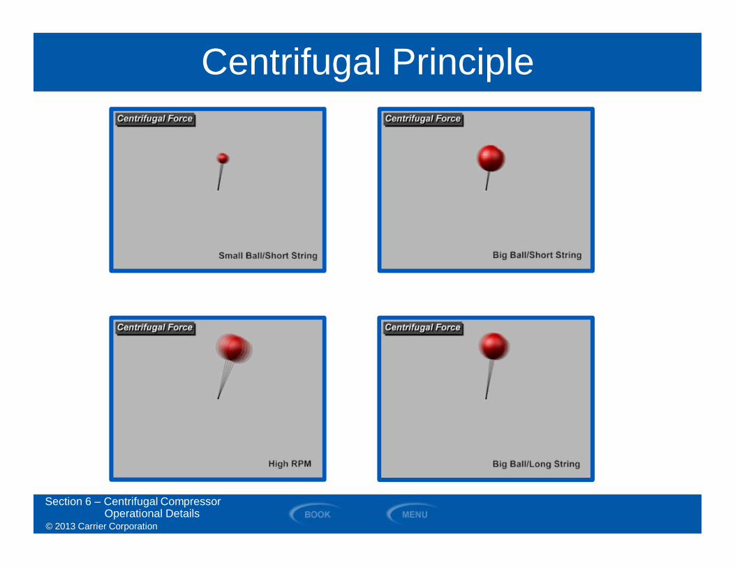
Centrifugal Compressor Theory• Heavier the ball (molecular weight) = MORE FORCE• Longer the string (diameter) = MORE FORCE• Faster the ball rotates (rpm) = MORE FORCE
Section 6 – Centrifugal CompressorOperational Details

© 2013 Carrier Corporation
Centrifugal Compressor Theory
Section 6 – Centrifugal CompressorOperational Details
© 2013 Carrier Corporation
Centrifugal Principle
Section 6 – Centrifugal CompressorOperational Details

© 2013 Carrier Corporation
Centrifugal Principle
Section 6 – Centrifugal CompressorOperational Details
© 2013 Carrier Corporation
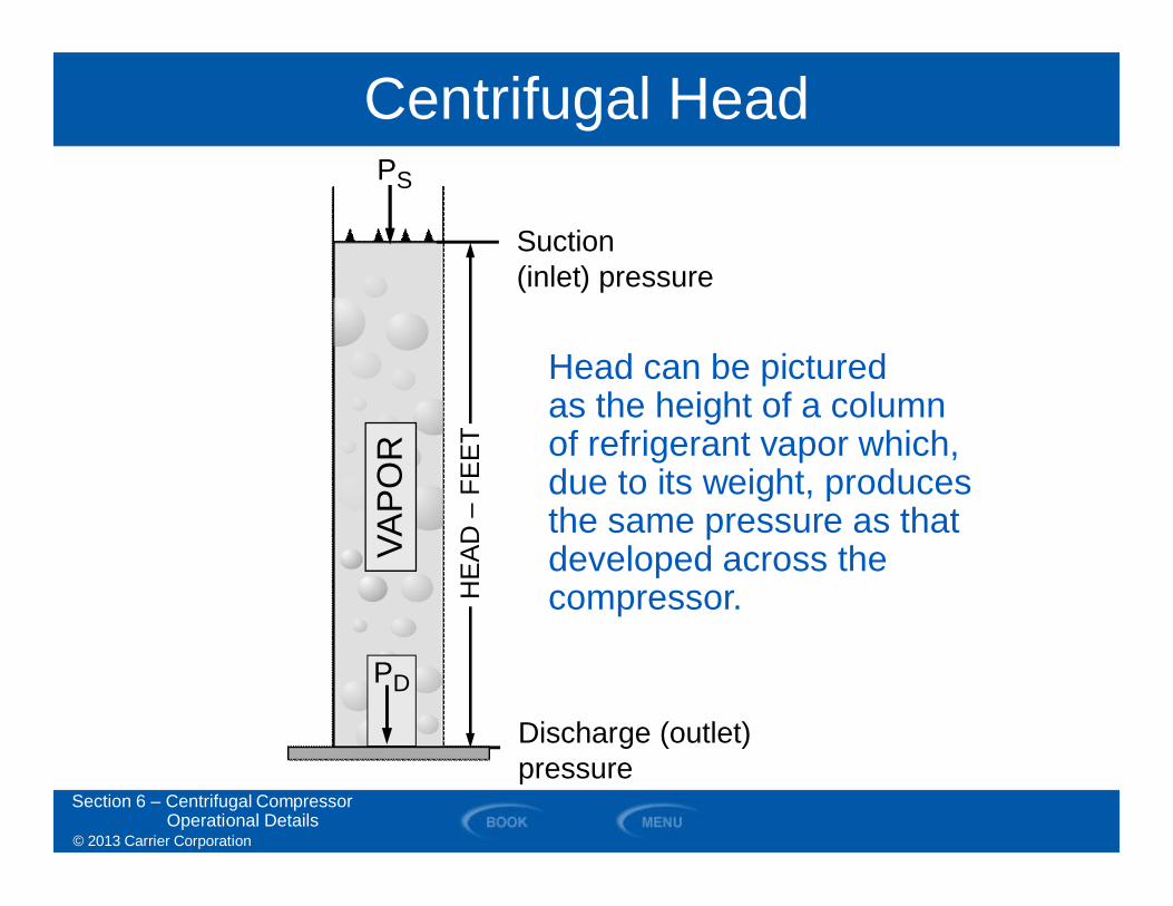
Centrifugal Head
Section 6 – Centrifugal CompressorOperational Details
VAP
OR
PS
HE
AD
–FE
ET
PD
Discharge (outlet)pressure
Suction(inlet) pressure
Head can be picturedas the height of a columnof refrigerant vapor which,due to its weight, producesthe same pressure as thatdeveloped across thecompressor.
© 2013 Carrier Corporation
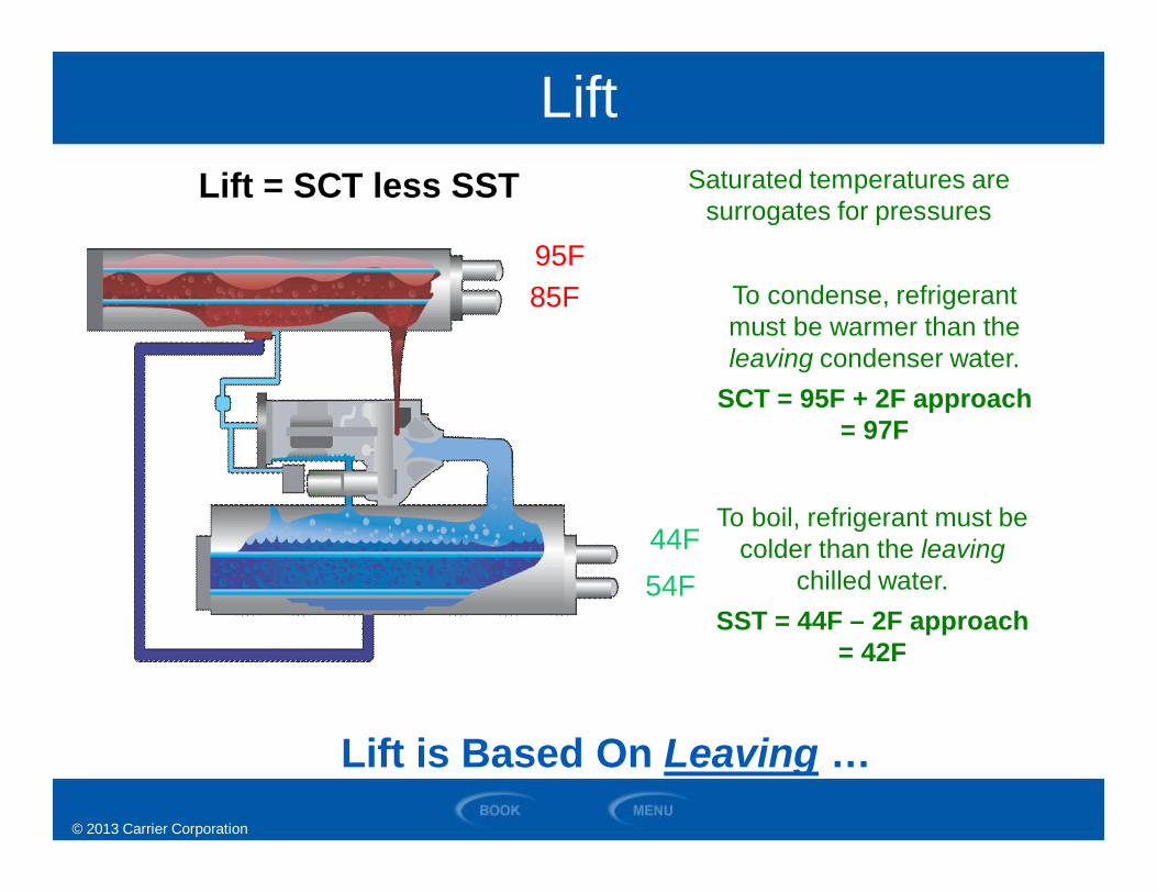
To condense, refrigerantmust be warmer than theleaving condenser water.
SCT = 95F + 2F approach= 97F
To boil, refrigerant must becolder than the leaving
chilled water.SST = 44F – 2F approach
= 42F
44F
Lift is Based On Leaving …
Lift = SCT less SST Saturated temperatures aresurrogates for pressures
95F
44F
85F
54F
Lift
© 2013 Carrier Corporation
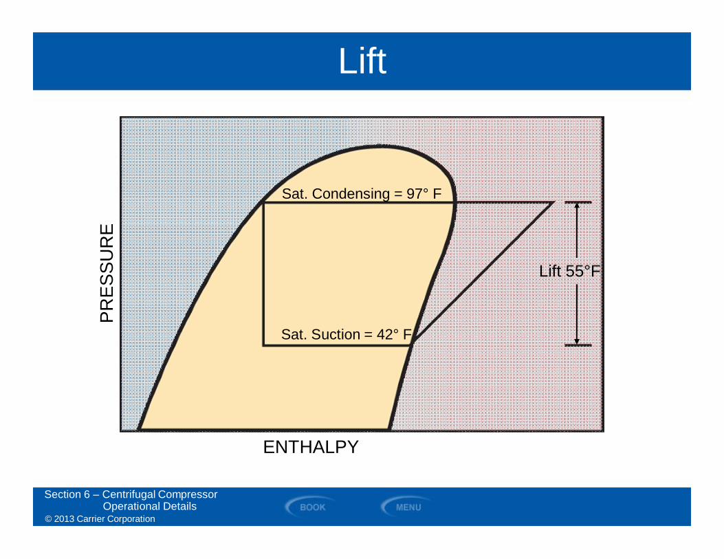
Lift
Lift 55°F
Sat. Condensing = 97° F
Sat. Suction = 42° F
Section 6 – Centrifugal CompressorOperational Details
PRES
SUR
E
ENTHALPY
© 2013 Carrier Corporation
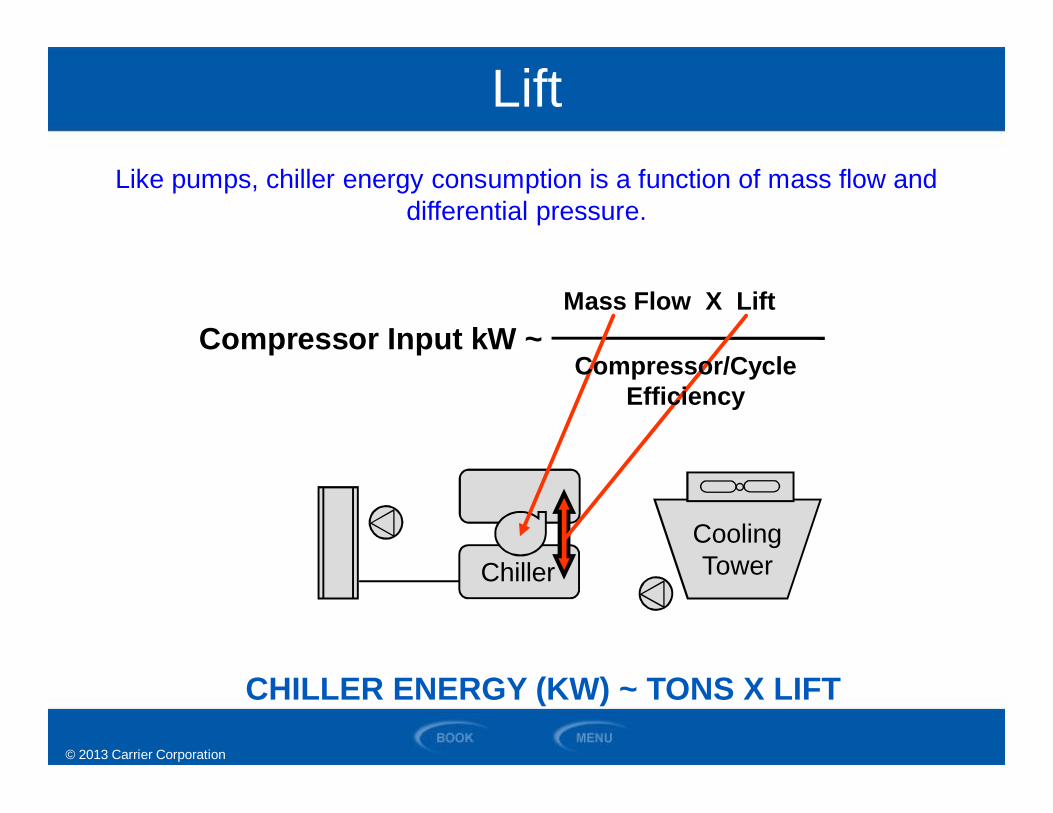
Compressor Input kW ~Mass Flow X Lift
ChillerCoolingTower
Compressor/CycleEfficiency
CHILLER ENERGY (KW) ~ TONS X LIFT
Like pumps, chiller energy consumption is a function of mass flow anddifferential pressure.
Lift
© 2013 Carrier Corporation
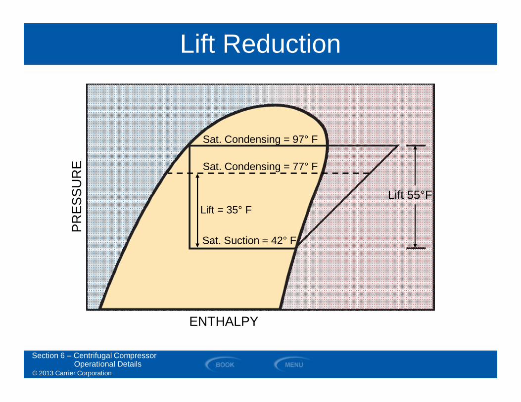
Lift Reduction
Sat. Condensing = 97° F
Sat. Suction = 42° F
Sat. Condensing = 77° F
Lift = 35° F
Section 6 – Centrifugal CompressorOperational Details
Lift 55°F
PRES
SUR
E
ENTHALPY
© 2013 Carrier Corporation
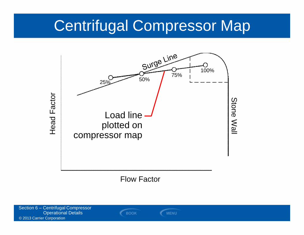
Centrifugal Compressor MapH
ead
Fact
or
Flow Factor
Load lineplotted on
compressor map
StoneW
all
Section 6 – Centrifugal CompressorOperational Details
100%75%
50%25%
© 2013 Carrier Corporation
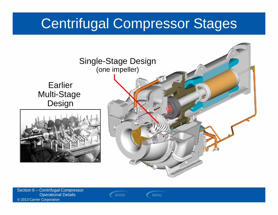
Centrifugal Compressor Stages
Section 6 – Centrifugal CompressorOperational Details
Single-Stage Design(one impeller)
EarlierMulti-Stage
Design
© 2013 Carrier Corporation
SECTION 7
Capacity Control Methods
WATER-COOLED CHILLERS
© 2013 Carrier Corporation
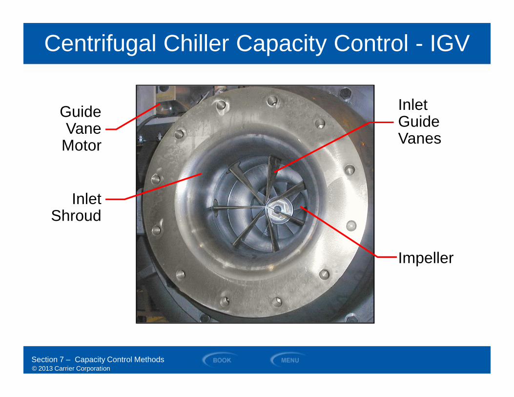
Centrifugal Chiller Capacity Control - IGV
GuideVane
Motor
InletShroud
InletGuideVanes
Impeller
Section 7 – Capacity Control Methods
© 2013 Carrier Corporation
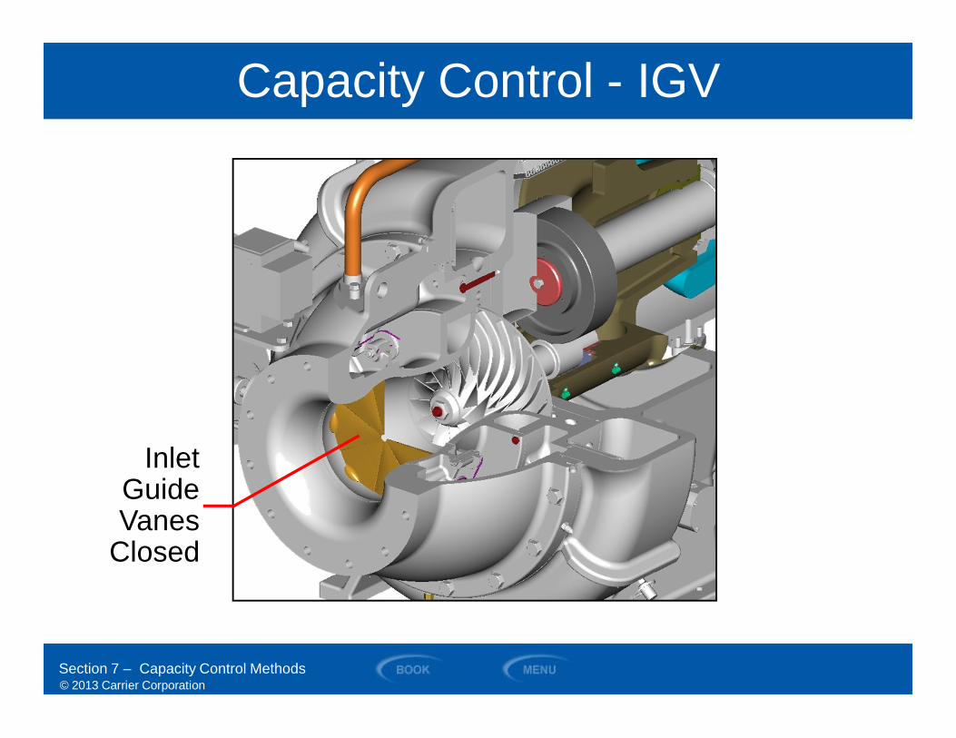
Capacity Control - IGV
InletGuideVanes
Closed
Section 7 – Capacity Control Methods
© 2013 Carrier Corporation
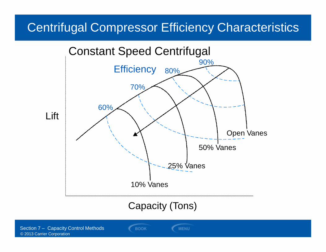
Centrifugal Compressor Efficiency Characteristics
Constant Speed Centrifugal
Open Vanes
50% Vanes
Efficiency90%
80%
70%
60%
25% Vanes
10% Vanes
Capacity (Tons)
Lift
Section 7 – Capacity Control Methods
© 2013 Carrier Corporation
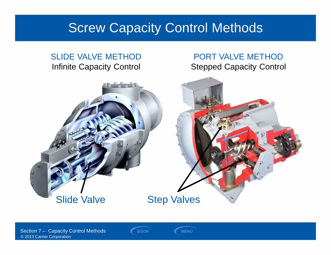
Screw Capacity Control Methods
SLIDE VALVE METHODInfinite Capacity Control
PORT VALVE METHODStepped Capacity Control
Section 7 – Capacity Control Methods
Step ValvesSlide Valve
© 2013 Carrier Corporation
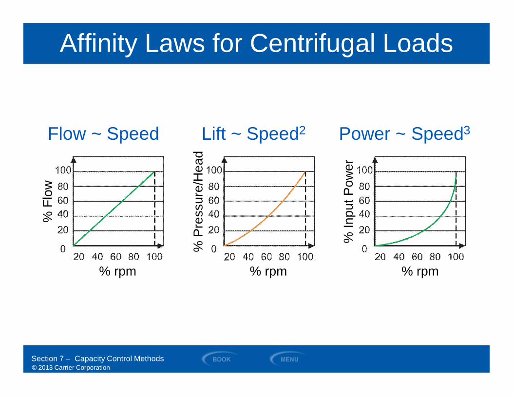
Affinity Laws for Centrifugal Loads
Section 7 – Capacity Control Methods
Flow ~ Speed
% rpm
%Fl
ow
Lift ~ Speed2
% rpm
%Pr
essu
re/H
ead
Power ~ Speed3
% rpm
%In
putP
ower
© 2013 Carrier Corporation
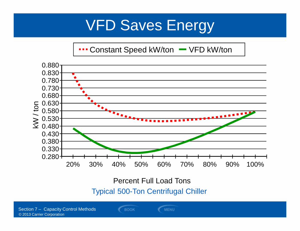
Constant Speed kW/ton VFD kW/ton
VFD Saves Energy
0.2800.3300.3800.4300.4800.5300.5800.6300.6800.7300.7800.8300.880
20% 30% 40% 50% 60% 70% 80% 90% 100%
Percent Full Load Tons
kW/t
on
Section 7 – Capacity Control Methods
Typical 500-Ton Centrifugal Chiller
© 2013 Carrier Corporation
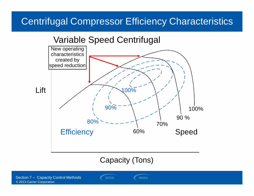
Centrifugal Compressor Efficiency Characteristics
Lift
Capacity (Tons)
90%
100%
80%
100%90 %
70%60% SpeedEfficiency
Variable Speed CentrifugalNew operatingNew operatingcharacteristics
created byspeed reduction
Section 7 – Capacity Control Methods
© 2013 Carrier Corporation
SECTION 8
Refrigerant Related Topics
WATER-COOLED CHILLERS
© 2013 Carrier Corporation
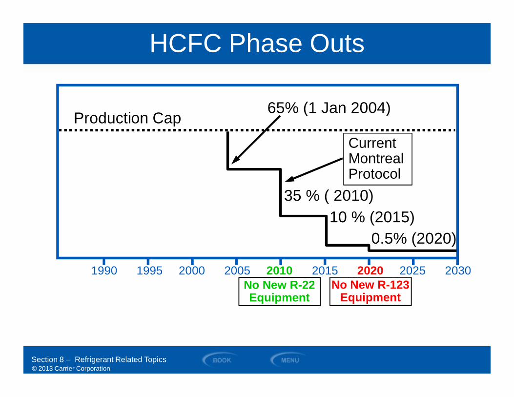
HCFC Phase Outs
1990 1995 2000 2005 2010 2015 2020 2025 2030
35 % ( 2010)10 % (2015)
0.5% (2020)
65% (1 Jan 2004)
CurrentMontrealProtocol
Production Cap
123No New R-123Equipment
Section 8 – Refrigerant Related Topics
No New R-22Equipment
© 2013 Carrier Corporation
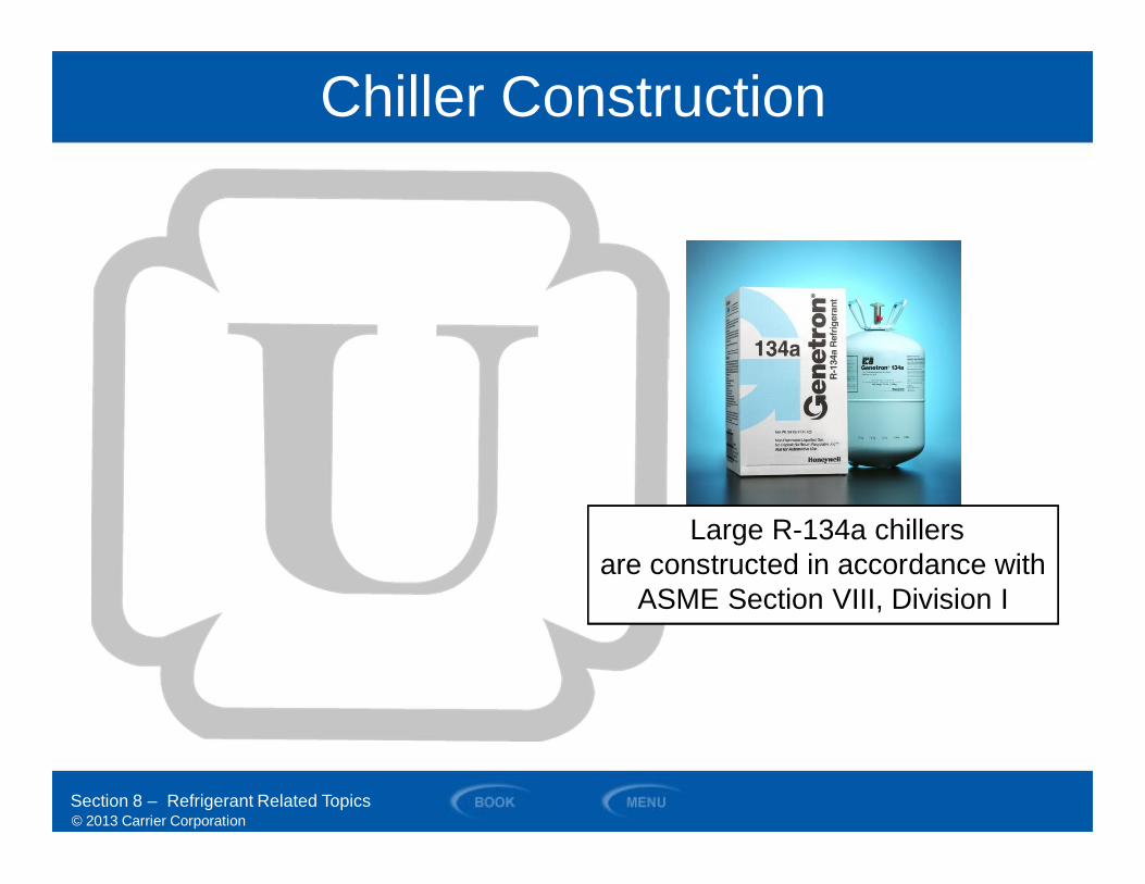
Chiller Construction
Section 8 – Refrigerant Related Topics
Large R-134a chillersare constructed in accordance with
ASME Section VIII, Division I
© 2013 Carrier Corporation
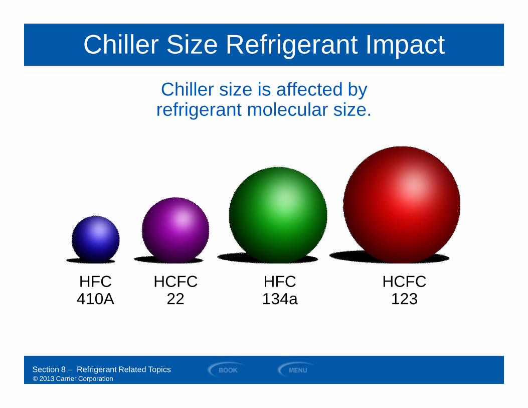
Chiller Size Refrigerant Impact
HCFC22
HFC134a
HCFC123
HFC410A
Section 8 – Refrigerant Related Topics
Chiller size is affected byrefrigerant molecular size.
© 2013 Carrier Corporation
Exp
osur
eLi
mits
Safety
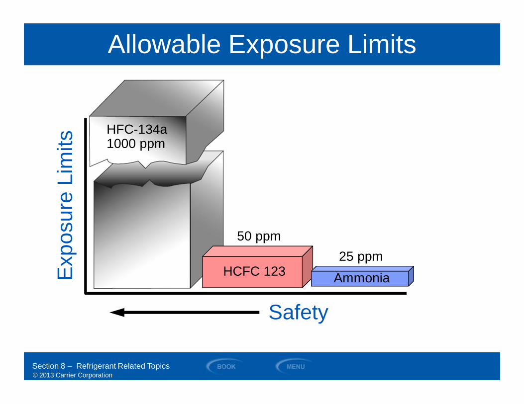
Allowable Exposure Limits
HFC-134a1000 ppm
HCFC 123
50 ppm
Section 8 – Refrigerant Related Topics
25 ppmAmmonia
© 2013 Carrier Corporation
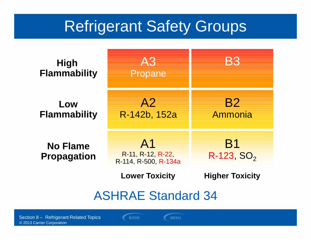
Lower Toxicity Higher Toxicity
A3Propane
B3
B2Ammonia
A2R-142b, 152a
A1R-11, R-12, R-22,
R-114, R-500, R-134a
B1R-123, SO2
LowFlammability
HighFlammability
No FlamePropagation
Refrigerant Safety Groups
Section 8 – Refrigerant Related Topics
ASHRAE Standard 34

© 2013 Carrier Corporation
SECTION 9
Heat Transfer
WATER-COOLED CHILLERS
© 2013 Carrier Corporation
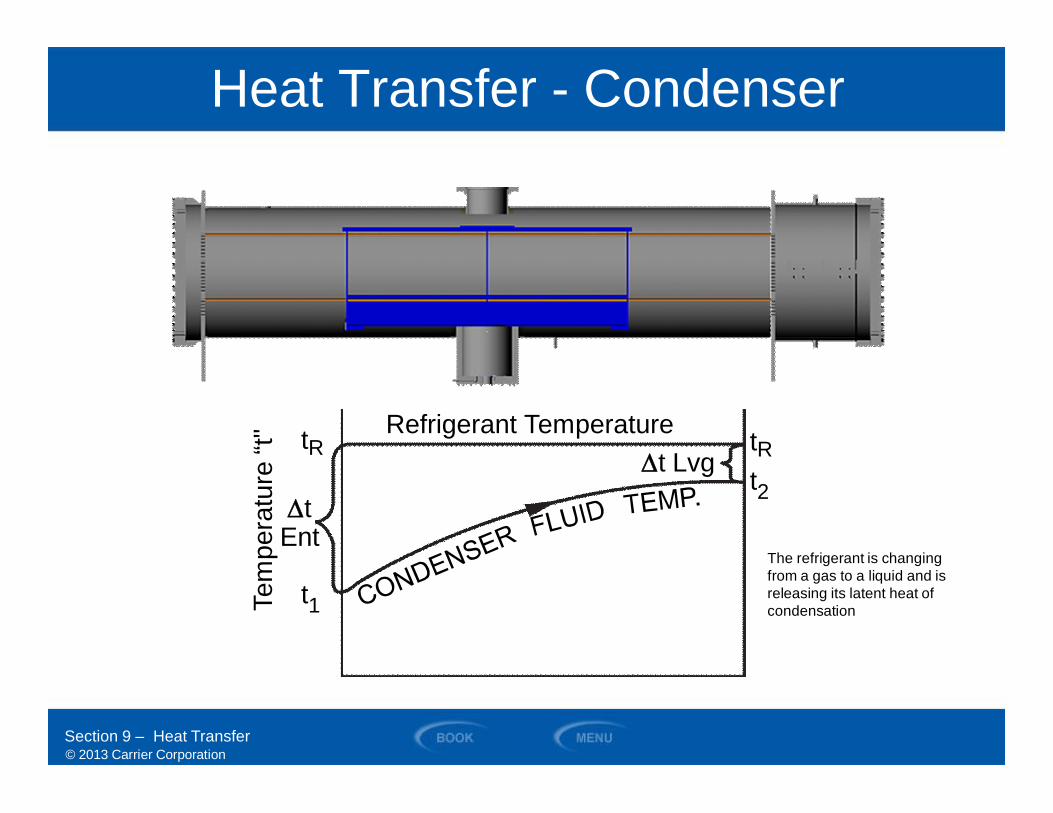
Heat Transfer - Condenser
Section 9 – Heat Transfer
Refrigerant Temperature
Tem
pera
ture
“t"
t1
tRt2
tR
DtEnt
Dt Lvg
The refrigerant is changingfrom a gas to a liquid and isreleasing its latent heat ofcondensation
© 2013 Carrier Corporation
Heat Transfer - Evaporator
Section 9 – Heat Transfer
tRRefrigerant TemperatureTe
mpe
ratu
re“t" t1
DtEnt
tR
t2Dt
Lvg
The refrigerant is changingfrom a liquid to agas while absorbing itslatent heat of vaporization
© 2013 Carrier Corporation
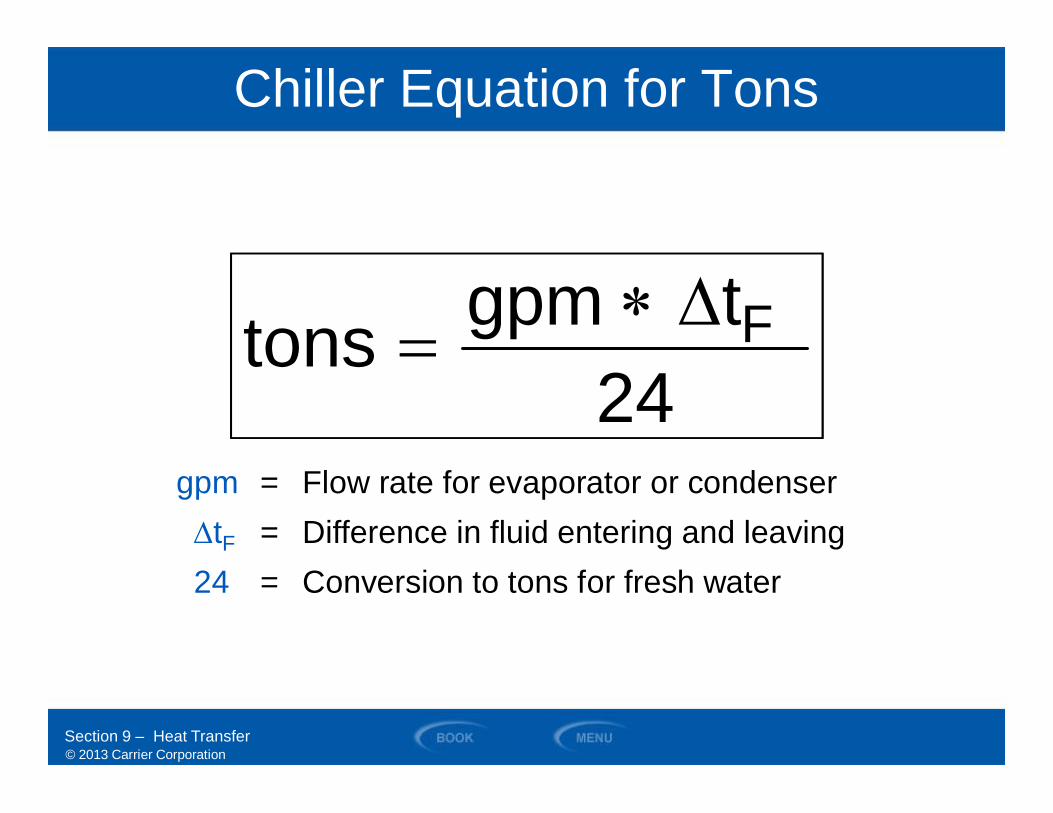
Chiller Equation for Tons
24tgpmtons FD*=
24tgpmtons FD*=
Section 9 – Heat Transfer
gpm = Flow rate for evaporator or condenserDtF = Difference in fluid entering and leaving24 = Conversion to tons for fresh water
© 2013 Carrier Corporation
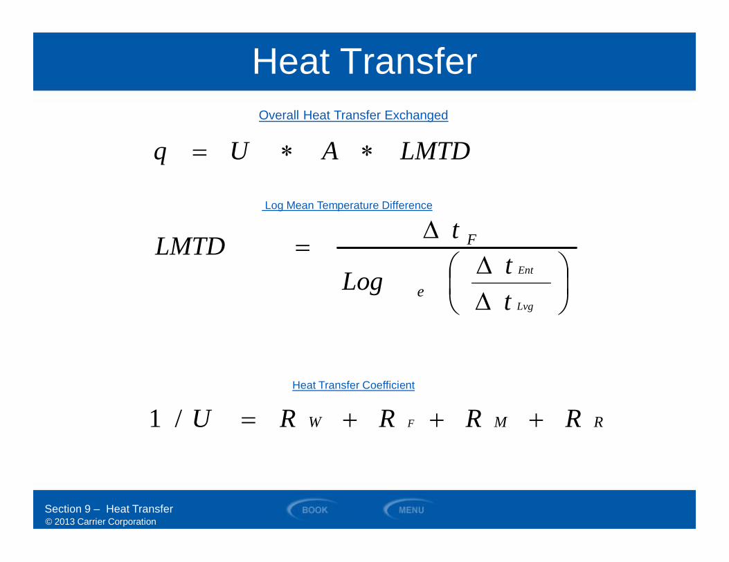
Heat Transfer
RMW
e
F
RRRRU
ttLog
tLMTD
LMTDAUq
F
Lvg
Ent
+++=
÷øö
çèæDD
D=
**=
/1
Section 9 – Heat Transfer
Overall Heat Transfer Exchanged
Log Mean Temperature Difference
Heat Transfer Coefficient
© 2013 Carrier Corporation
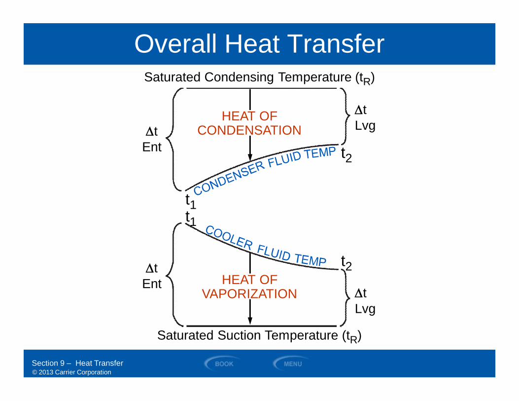
HEAT OFCONDENSATION
HEAT OFVAPORIZATION
t2
t2
t1t1
Saturated Suction Temperature (tR)
Section 9 – Heat Transfer
Saturated Condensing Temperature (tR)
Overall Heat Transfer
DtLvg
DtLvgDt
Ent
DtEnt
© 2013 Carrier Corporation
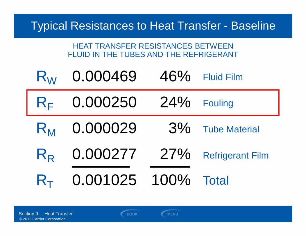
Typical Resistances to Heat Transfer - Baseline
Section 9 – Heat Transfer
HEAT TRANSFER RESISTANCES BETWEENFLUID IN THE TUBES AND THE REFRIGERANT
0.000469
0.000250
0.000029
0.000277
0.001025
RW
RF
RM
RR
RT
46%
24%
3%
27%
100%
Fluid Film
Fouling
Tube Material
Refrigerant Film
Total
© 2013 Carrier Corporation
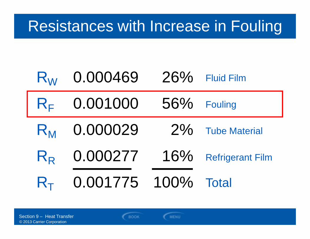
0.000469
0.001000
0.000029
0.000277
0.001775
RW
RF
RM
RR
RT
26%
56%
2%
16%
100%
Resistances with Increase in Fouling
Section 9 – Heat Transfer
Fluid Film
Fouling
Tube Material
Refrigerant Film
Total

© 2013 Carrier Corporation
Fouling is the build-up of deposits on tube surfaces anddepends on the quality of water (i.e., dirty river, etc.)
• Expressed as a number(0.00025 or 0.0005 or 0.002)
• Minimal in evaporators– Closed piping circuit
• Greater in condensers
• ARI 0.00025 fouling factor– Basis of chiller ratings
for condensers– For evaporators 0.0001
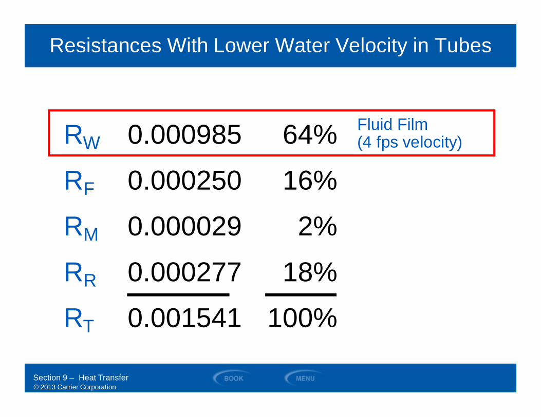
• Lower water velocitiesresult in higherfouling rates
RefrigerantFilm RR
Metal RM
Water Film RW
Refrigerant
Fouling (Scaling Resistance) RF
Scale(Fouling) RF
Water in Tube
Resistant Layers
Water
Hea
tFlo
w
Section 9 – Heat Transfer
© 2013 Carrier Corporation
Resistances With Lower Water Velocity in Tubes
Section 9 – Heat Transfer
0.000985
0.000250
0.000029
0.000277
0.001541
RW
RF
RM
RR
RT
64%
16%
2%
18%
100%
Fluid Film(4 fps velocity)
© 2013 Carrier CorporationSection 9 – Heat Transfer
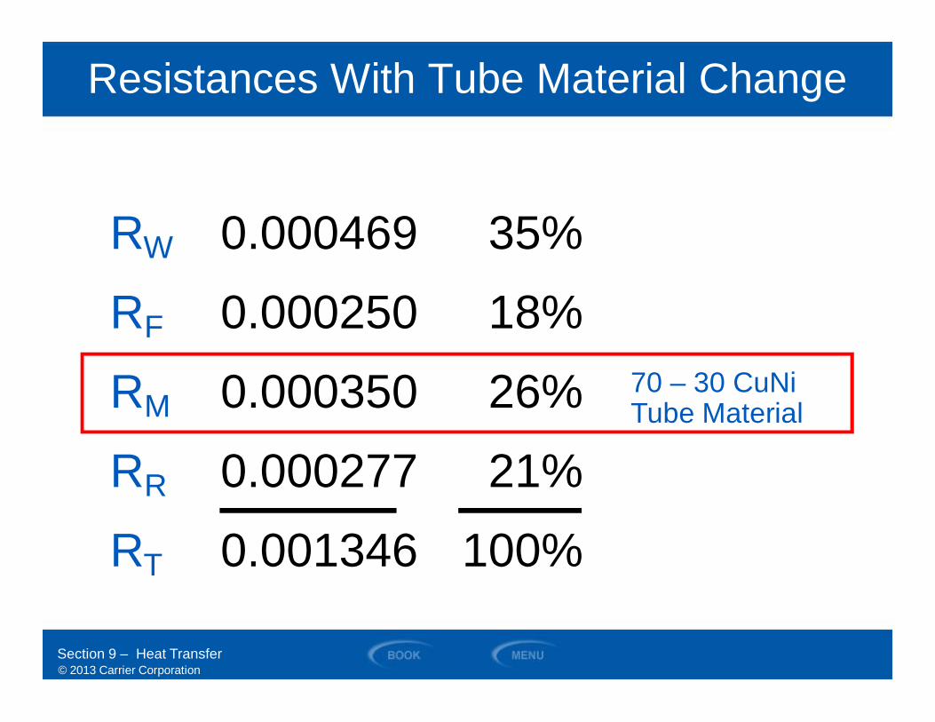
Resistances With Tube Material Change
0.000469
0.000250
0.000350
0.000277
0.001346
RW
RF
RM
RR
RT
35%
18%
26%
21%
100%
70 – 30 CuNiTube Material
© 2013 Carrier Corporation
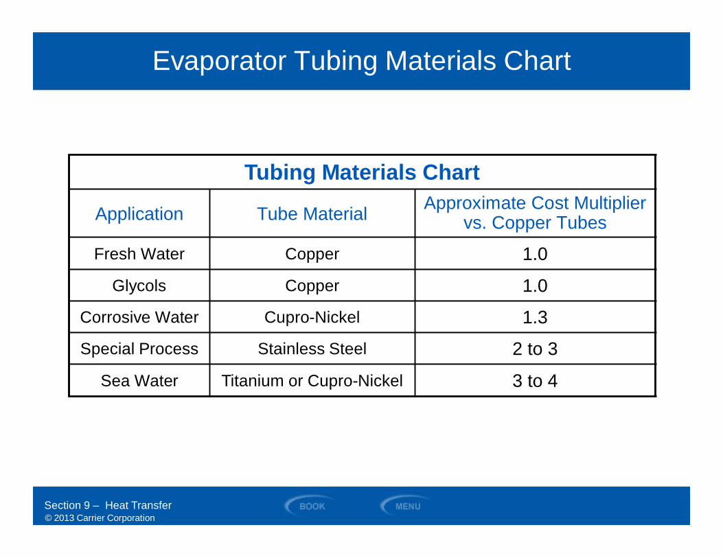
Evaporator Tubing Materials Chart
Tubing Materials Chart
Application Tube Material Approximate Cost Multipliervs. Copper Tubes
Fresh Water Copper 1.0
Glycols Copper 1.0
Corrosive Water Cupro-Nickel 1.3
Special Process Stainless Steel 2 to 3
Sea Water Titanium or Cupro-Nickel 3 to 4
Section 9 – Heat Transfer
© 2013 Carrier Corporation
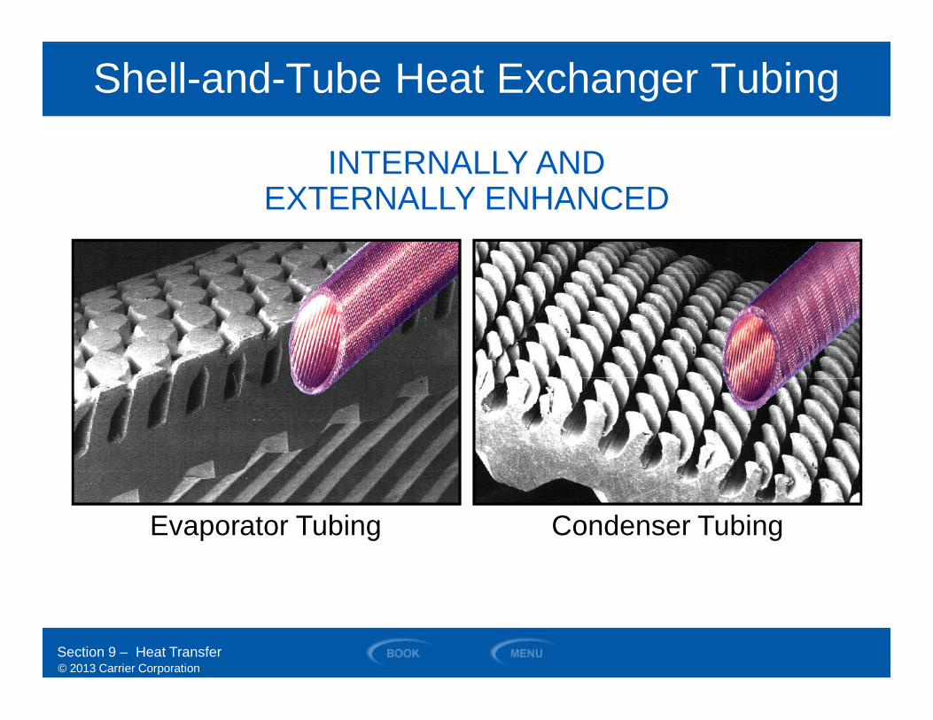
Shell-and-Tube Heat Exchanger Tubing
Section 9 – Heat Transfer
INTERNALLY ANDEXTERNALLY ENHANCED
Condenser TubingEvaporator Tubing
© 2013 Carrier Corporation
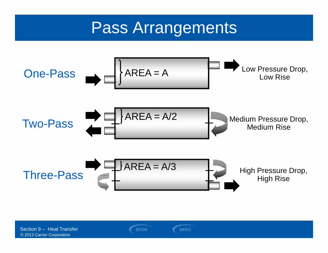
Pass Arrangements
One-Pass AREA = A
Two-PassAREA = A/2
Three-PassAREA = A/3
Low Pressure Drop,Low Rise
Medium Pressure Drop,Medium Rise
High Pressure Drop,High Rise
Section 9 – Heat Transfer
© 2013 Carrier Corporation
SECTION 10
Codes and Standards
WATER-COOLED CHILLERS
© 2013 Carrier Corporation
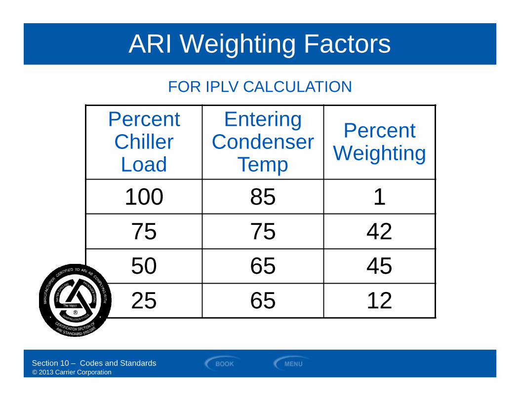
ARI Weighting Factors
PercentChillerLoad
EnteringCondenser
TempPercent
Weighting
100 85 175 75 4250 65 4525 65 12
Section 10 – Codes and Standards
FOR IPLV CALCULATION
© 2013 Carrier Corporation
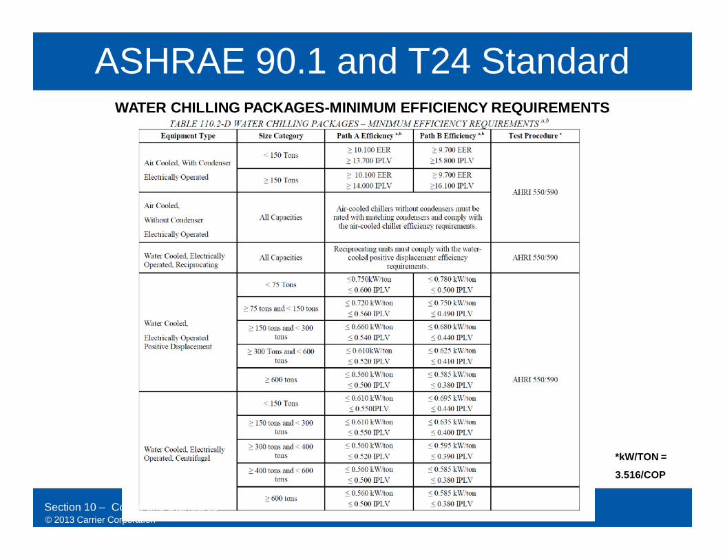
ASHRAE 90.1 and T24 Standard
Section 10 – Codes and Standards
*kW/TON =
3.516/COP
WATER CHILLING PACKAGES-MINIMUM EFFICIENCY REQUIREMENTS
© 2013 Carrier Corporation
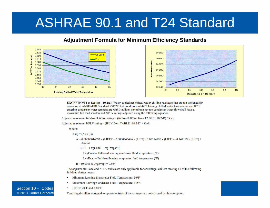
ASHRAE 90.1 and T24 Standard
Section 10 – Codes and Standards
Adjustment Formula for Minimum Efficiency Standards
0.540
0.560
0.580
0.600
0.620
0.640
0.660
9 10 11 12 13 14 15
Condenser Delta T
IKW
/Ton
Req
uire
d
© 2013 Carrier Corporation
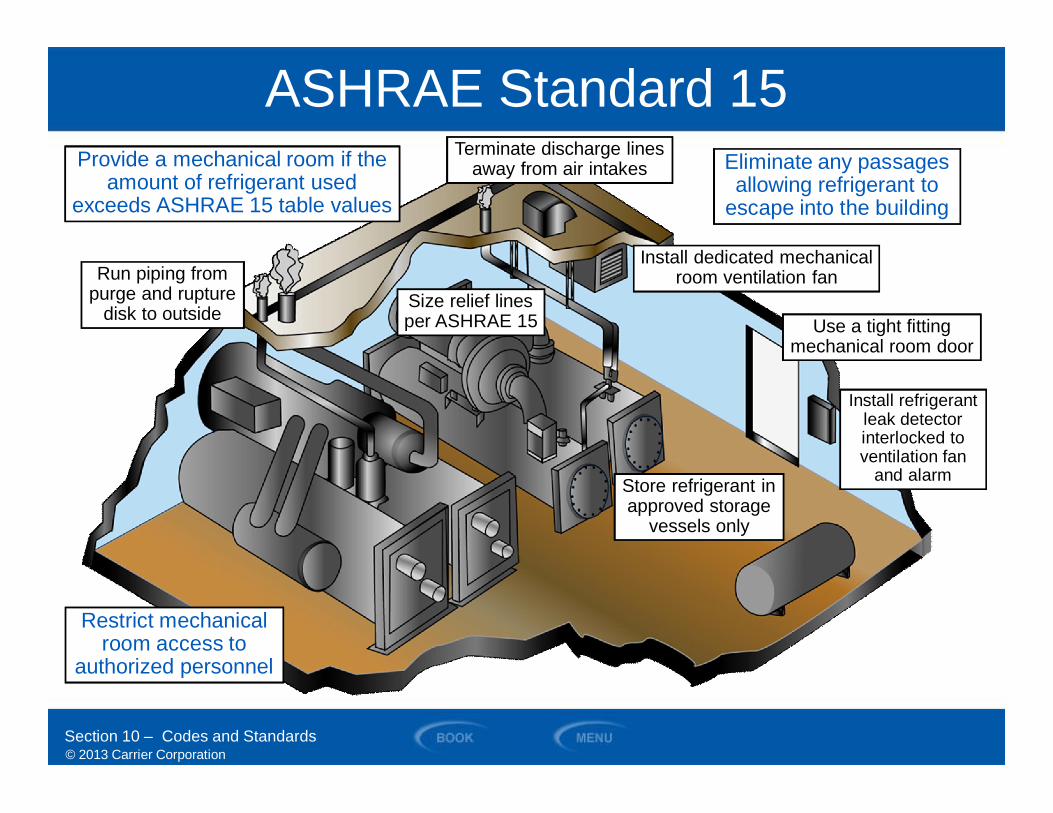
ASHRAE Standard 15
Run piping frompurge and rupture
disk to outside
Provide a mechanical room if theamount of refrigerant used
exceeds ASHRAE 15 table values
Install dedicated mechanicalroom ventilation fan
Eliminate any passagesallowing refrigerant to
escape into the building
Store refrigerant inapproved storage
vessels only
Restrict mechanicalroom access to
authorized personnel
Section 10 – Codes and Standards
Size relief linesper ASHRAE 15 Use a tight fitting
mechanical room door
Terminate discharge linesaway from air intakes
Install refrigerantleak detectorinterlocked toventilation fan
and alarm
© 2013 Carrier Corporation
SECTION 11
Selection Criteria
WATER-COOLED CHILLERS
© 2013 Carrier Corporation
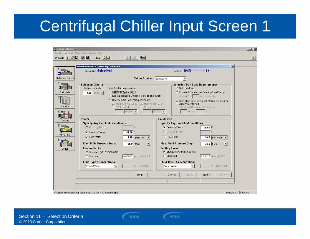
Centrifugal Chiller Input Screen 1
Section 11 – Selection Criteria
© 2013 Carrier Corporation
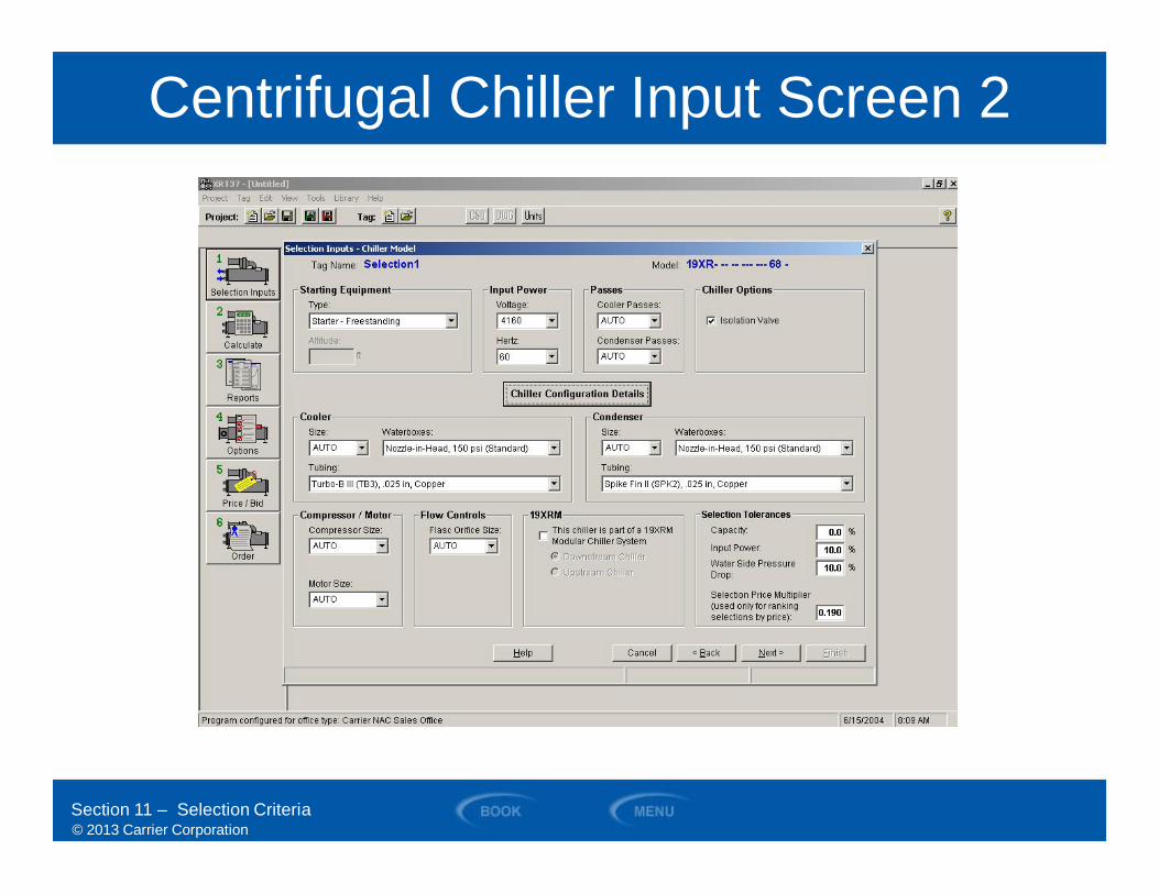
Centrifugal Chiller Input Screen 2
Section 11 – Selection Criteria

© 2013 Carrier Corporation
SECTION 12
Summary
WATER-COOLED CHILLERS
© 2013 Carrier Corporation
Summary
Section 12 – Summary
• Compared the advantages of water-cooledversus air-cooled chillers
• Identified and diagrammed the differentcomponents of a basic refrigeration cycleas it applies to a water-cooled chiller
• Compared and described the differences amongscroll, reciprocating, centrifugal, and screwwater-cooled chillers and their applications
• Discussed the differences in constructionof water-cooled chillers of various sizes
• Identified the codes and standardsthat apply to water-cooled chillers
• Reviewed the typical inputs requiredto select a water-cooled chiller
© 2013 Carrier Corporation
Technical Development Program
Thank YouThis completes the presentation.