comm/data protection guide - tii network technologies, inc
TRANSCRIPT

COMM/DATA PROTECTION GUIDE
Lightning and Surge Protection for
Comm/Data Networks
APRIL 2011

TABLE OF CONTENTS...........................................................................................1-2
NETWORK PROTECTION AND HAZARDS TO YOUR NETWORK..................... 3
RESPONSE OF VARIOUS TRANSIENT PROTECTORS...................................... 4
RECOMMENDED PROTECTION FOR VARIOUS APPLICATIONS..................... 5
PRIMARY PROTECTION MODULES..................................................................... 6-8 GAS TUBE: HIGH ENERGY, ECONOMICAL, LOW CAPACITANCE,
SOLID STATE: FAST RESPONSE, LOW ENERGY LET-THROUGH,
LOW VOLTAGE DATA PROTECTORS: HIGH FREQUENCY DATA
DELTA: HIGH ENERGY, FAST RESPONSE,
DSL MODULE: LOW CAPACITANCE, BALANCED, FAST RESPONSE,
BUILDING ENTRANCE TERMINALS (BET) Series Overview................................................................................................... 9-10 SERIES 24, 25, and 26 OVERVIEW AND COMPARISON
Series 24: 66 Terminations......................................................................................11 SPECIFICATIONS, MODEL NUMBERS, AND ORDERING INFORMATION
Series 24: 110 Terminations.................................................................................... 12 SPECIFICATIONS, MODEL NUMBERS, AND ORDERING INFORMATION
Series 25: 66 & 110 Terminations............................................................................. 13 SPECIFICATIONS, MODEL NUMBERS, AND ORDERING INFORMATION
Series 25: Stub Input.............................................................................................. 14 SPECIFICATIONS, MODEL NUMBERS, AND ORDERING INFORMATION
Series 26: Stub Input & Output................................................................................ 15 SPECIFICATIONS, MODEL NUMBERS, AND ORDERING INFORMATION
SERIES 28 XLBET EXTRA LARGE BUILDING ENTRANCE TERMINAL............ 16-17 HIGH PAIR COUNT PROTECTION AND DISTRIBUTION ON 23" RACKS
CATEGORY 6 PROTECTION PRODUCTS 606 Protector Packs............................................................................................... 18
CATEGORY 5E PROTECTION PRODUCTS......................................................... 19 505E Protector Packs MODULAR PROTECTOR PACKS FOR HIGH-SPEED DATA AND OTHER LOW VOLTAGE APPLICATIONS
GENERAL APPLICATION PROTECTOR PACKS, 5-PIN STYLE...............................20 5-Pin Building Entrance Protectors SPECIFICATIONS, MODEL NUMBERS, AND ORDERING INFORMATION
1 • Customer Service • 888.844.4720 • www.tiinetworktechnologies.com
Table of Contents

GENERAL APPLICATION PROTECTOR PACKS, 1-PIN STYLE.............................. 21 504 and 581 66/110 TERMINATION PROTECTION OF TELEPHONE SYSTEMS
POWER FAIL TRANSFER UNIT.............................................................................21 578 Linebacker (PFTU) EMERGENCY TELEPHONE SERVICE DURING A POWER FAILURE
CENTRAL OFFICE PROTECTOR BLOCKS P399: 100-Pair Protector Block................................................................................ 22-23 SPECIFICATIONS, MODEL NUMBERS, AND ORDERING INFORMATION
P310: 100-Pair Protector Block................................................................................24-25 SPECIFICATIONS, MODEL NUMBERS, AND ORDERING INFORMATION
DISTRIBUTION FRAME EQUIPMENT....................................................................26 88 Terminal Block Family to connect equipment on distribution frames
OSP PROTECTOR BLOCKS P307: 100-Pair Connector Block.............................................................................. 27-28 SPECIFICATIONS, MODEL NUMBERS, AND ORDERING INFORMATION
OSP RACKMOUNT PROTECTOR PANELS
19", RJ45-Connect Panel........................................................................................29 SPECIFICATIONS, MODEL NUMBERS, AND ORDERING INFORMATION
19", 66-Connect Panel............................................................................................ 30 SPECIFICATIONS, MODEL NUMBERS, AND ORDERING INFORMATION
19", 110-Connect Panel...........................................................................................31 SPECIFICATIONS, MODEL NUMBERS, AND ORDERING INFORMATION
19", 100-Pair Panel................................................................................................. 32-33 SPECIFICATIONS, MODEL NUMBERS, AND ORDERING INFORMATION
19", 110-Pair, 110-Connect Panel..............................................................................34 SPECIFICATIONS, MODEL NUMBERS, AND ORDERING INFORMATION
23", 200-Pair Protector Panel...................................................................................35-36 SPECIFICATIONS, MODEL NUMBERS, AND ORDERING INFORMATION
COMPETITOR PRODUCT REFERENCE............................................................... 37-38
2All Specifications Subject to Change Without Notice
Table of Contents(cont'd)
L INE PROTECTION SOLUTIONSProducts

Network Protection
Sophisticated Equipment Demands Sophisticated Protection
Lightning: By far the most common cause of electrical surge damage to the communications network is lightning. Lightning can enter your network in a number of ways. It might strike a tele-phone or power line, causing high voltage to enter the equipment through incoming lines, or it might strike the ground and travel along buried cables.
Power Crosses: Power crosses refer to incidents where a communications line comes in physical contact with an electrical power line. This could be caused by a downed telephone pole where phone and electrical lines have crossed. These incidents cause excessive AC current con-ditions to be carried into the communications system.
Power Faults: Power faults should not to be confused with power crosses. In most buildings, the power company’s neutral line is bonded to the telephone company’s cable. If current is introduced onto this neutral line by any means, it can be transferred to the communications line and into the equipment.
Induction: Communications lines need not come in direct physical contact with lightning or power overloads for a voltage spike or surge to be introduced on a line. These hazards can be induced from nearby sources such as the magnetic field surrounding a power line. Furthermore, when a brown out occurs, the power surge that accompanies the return to normal service can be transferred to nearby communications lines.
Electrostatic Discharge: Most people have experienced the effects of electrostatic discharge in the home by simply walking across a carpet, touching a metal object and receiving a small shock. Similar type of shocks can be transmitted to communications circuits through the build-up and dis-charge of energy in dry climates.
• An unprotected or insufficiently protected communications network is a hazard to both your employee’s safety and your bottom line.
• When a communications line is protected by Porta Systems products, hazards are quickly and safely shorted to ground.
H A Z A R D S T O Y O U R N E T W O R K
3 • Customer Service • 888.844.4720 • www.tiinetworktechnologies.com

Gas Discharge Tube (GDT)
Response of Various Transient Protectors
• A robust balanced three-electrode design. • Automatically resets after current surges of up to 10,000 Amps and high voltages. • Attractive for protecting high-speed carrier lines, such as T1, due to Ultra Low Capacitance.
4
Solid State (S.S.)
• Solid State thyristor based design. • Tighter voltage range which results in lower over-shoot voltage. • Quick transient response time. • Automatically resets after current surges of up to 100 Amps.
Delta (GDT/TVS)
• A robust balanced three-electrode GDT coordinated with Transient Voltage Suppressor (TVS) diodes. • Tighter voltage range which results in lower over-shoot voltage. • Quick transient response time. • Automatically resets after current surges of up to 20,000 Amps and high voltages.
Response of Overvoltage Protector
Nanosecond = Billionth of a Second Actual waveshapes recorded by Tektronix TDS520 Oscilloscope
10KV/uSec (1KV pulse)
0
100
200
300
400
500
0 100 200 300 400 500 600 700 800 900 1000
230V Gas Tube (GDT)
230V Delta- (GDT/Solid State)
230V Solid State (S.S.) 230V Nominal
Over-Shoot Voltage
Time (NanoSeconds)
Vo
lts
(V)
Response Time
All Specifications Subject to Change Without Notice L INE PROTECTION SOLUTIONSProducts

Performance Comparison Table
Protector TypeGas Discharge Tube
(GDT)Solid State (Thyristor)
Delta (GDT/TVS)
Response Time Good Best Best
Voltage Precision Good Better Best
Current Capability Better Good Best
Low Capacitance Best Good Better
Service Life Better Good Best
Recommended Protection of Various Applications
Telephony Signals
Model Technology Application
3B1E, 175BCXN-230 Gas Tube 230 Volt Analog (CO or Line Card), T1
4B1S, 115SCN-240 Solid State 240 Volt Digital (CO lines)
4B1S (75), 115SCN-75 Solid State 75 Volt Digital (Line Card)
195BCDXN-230 Delta 240 Volt Digital (CO lines)
195BCDXN-75 Delta 75 Volt Digital (Line Card)
Data Signals - (Low Capacitance, Low Voltage)
LVP18E1, LVP6-182 Solid State 18 Volt Ethernet/LAN
LVP27E1, LVP6-272 Solid State 27 Volt IP Cameras (12-24V applications)
LVP6-652 Solid State 65 Volt Ethernet/PoE Note 1: The LVP18E and LVP27E are for Category 5E networks when used in series 505 and 1504 blocks.
Note 2: The LVP6-18, LVP6-27 and LVP6-65 are for Category 6 networks when used in series 606 blocks.
Porta Systems is a leading provider of connection and protection products for public and private telecommunications networks. Porta Systems’ Delta, a hybrid Solid State and Gas Tube Protector Module, reacts to over- voltages in less than five nanoseconds and is the fastest in the industry. Over 100 patents for termination and protection products attest to Porta’s innovative engineering and support of voice and data networks.
Recommended Applications
5 • Customer Service • 888.844.4720 • www.tiinetworktechnologies.com

Over 400 Models—UL Listed Protection for Every Application (7.5V to 400V)
Primary Protection Modules
The Porta Systems family of protector modules provides primary voltage protection utilizing gas tube and solid state elements. Primary/Secondary voltage and current protec-tion is provided by incorporating one or more of the follow-ing technologies into the protection circuit:
• Gas Tubes • Thyristors • TVS Diodes • Metal Oxide Varistor (MOV) • Heat Coils • Heat Sensors • Sneak Current Fuses
115SCN 115SCNHDSL 175BCXN 195BCDXN
MLVP27 15SCN 75BCXN LVP27
6All Specifications Subject to Change Without Notice L INE PROTECTION SOLUTIONSProducts

ORDERING INFORMATION:CONFIGURATION OVERCURRENT PROTECTION 18V 27V 65V Single-Pin Sneak Fuse LVP18 LVP27 LVP65
Five-Pin Sneak Fuse MLVP18 MLVP27 MLVP65
Low Voltage Data Protectors - Cat 5e and Cat 6(UL LISTED. HIGH-FREQUENCY DATA, ALARM, CCTV)
For protection of LAN equipment and data communications circuits. Solid state technology provides fast reaction to hazardous voltage condi-tions and prevents damage to sensi-tive data equipment. For CAT 5E and Cat 6 applications use our 505E, 606 or 1504PX2 series blocks. (See pages 18-19).
Gas Tube Protector (UL LISTED. HIGH ENERGY, ECONOMICAL, LOW CAPACITANCE)
Provides a highly reliable and robust means of protecting equipment from high energy voltage and current surg-es (up to 10KA). The protector includes a heat-activated failsafe mechanism that provides protection against a sustained surge condition.
Primary Protection Modules
ORDERING INFORMATION:CONFIGURATION OVERCURRENT CROSS PROTECTOR REF. 75V 230V 400VSingle-Pin NA — — 75BCXN-230 75BCXN-400 Heat Coil — 95BCXN-75 95BCXN-230 95BCXN-400
Five-Pin NA 3B1E — 175BCXN-230 175BCXN-400 Heat Coil 4B1E 195BCXN-75 195BCXN-230 195BCXN-400
Solid State Protector (UL LISTED. FAST RESPONSE, LOW ENERGY LET-THROUGH)
With a response time of 5- nanoseconds, these protectors are recommended for protection of sensitive equipment. An integral fail-safe mechanism permanently shorts the protector to ground in the presence of a sustained surge condi-tion.
ORDERING INFORMATION:CONFIGURATION OVERCURRENT CROSS PROTECTOR REF. 75V 240V 300VSingle-Pin Heat Coil — 15SCN-75 15SCN-240 15SCN-300
Five-Pin Heat Coil 4B1S 115SCN-75 115SCN-240 115SCN-300 3B1S 105SCN-75 105SCN-240 105SCN-300
7 • Customer Service • 888.844.4720 • www.tiinetworktechnologies.com

DELTA™ Protector (UL LISTED. HIGH ENERGY, FAST RESPONSE)
Provides cutting edge, high-speed pro-tection for sensitive communications and data equipment particularly in high light-ning areas. The DELTATM coordinates very high speed diodes with a powerful, three-element gas tube for overvoltage protection. This provides fast response time (clamps in 5 nanoseconds) and high energy (20KA) sustainability. The DELTATM protector also provides over-current protection using heat coils.
ORDERING INFORMATION:CONFIGURATION OVERCURRENT PROTECTOR 75V 230V 350V
Single-Pin Heat Coil 95BCDXN-75 95BCDXN-230 95BCDXN-350 Five-Pin Heat Coil 195BCDXN-75 195BCDXN-230 195BCDXN-350
Primary Protection Modules
ORDERING INFORMATION:CONFIGURATION STYLE 230V Single-Pin SS/Heat Coil 15SCNHDSL-230
Five-Pin SS/Heat Coil 115SCNHDSL-230
(LOW CAPACITANCE, BALANCED, FAST RESPONSE)
Provides dependable protection for the broadband communication provider. Balanced, low capacitance circuitry minimizes reflection and extends DSL frequency operating range. Solid State components minimize energy let-through.
(UL LISTED. FAST RESPONSE, LOW ENERGY LET-THROUGH)
Provides dependable protection for the broadband communication provider. Balanced three- electrode gas tube design and low capacitance circuitry minimizes reflection, maximizes DSL frequency operating range and distance. Ideal for POTS, ISDN, ADSL2/2+, SDSL, HDSL, RADSL, and VDSL.
ORDERING INFORMATION:CONFIGURATION STYLE 230V 400V
Single-Pin GDT - 75AVN-400 Hybrid GDT/MOV 75HAVN-230 - Five-Pin GDT - 175AVN-400 Hybrid GDT/MOV 175HAVN-230 -
8All Specifications Subject to Change Without Notice
xDSL Protection Modules
L INE PROTECTION SOLUTIONSProducts

In order to safeguard buildings and person-nel from dangerous electrical surges, the National Electric Code (NEC) requires UL 497 Primary Protection for incoming com-munication lines. This requirement applies to Service Providers (Telcos) at their demarca-tion point, and to Customer Premise owners and installers for runs between buildings in industrial, commercial, or campus environ-ments. Failure to comply with this require-ment not only creates a potentially dangerous condition, but also can result in costly fines, rework, and destruction of sensitive equip-ment.
A Porta Systems Building Entrance Terminal (BET) equipped with its pri-mary protectors meets or exceeds these demands.
S E R I E S 2 4 B E T s
AVAILABLE WITH FACTORY INSTALLED & TESTED PROTECTORS •Available with Gas Tube modules at no additional charge. See pages 7 & 8 for protectors.
PAIR COUNT •Available in 25, 50 and 100 pairs
INPUT TERMINATION •Available in 66, 110, 710, MS2
•Custom inputs available—contact Customer Service
OUTPUT TERMINATION •Available in 66, 110, RJ 21
INTERNAL FUSIBLE LINK
SPLICE CHAMBER WITH COVER •Cable knock outs for top or bottom cable entry •Small swing radius— more room in tight quarters
OPTIONAL LOCKABLE PROTECTOR & EQUIPMENTSIDE COVER
MULTIGROUND BUS BAR •Allows approved bonding termination point
LINE DESIGNATION STRIP
VERTICALLY STACKABLE •Up to 400 pairs
CONSTRUCTION •18 gauge welded steel housing •Durable finish •Compact, light weight, rugged
Building Entrance Terminals (BETs)
Suitable for use by both Service Providers (Telcos) at their demarcation point and Customer Premise owners and installers for runs between buildings in an industrial, commercial, or campus environment.
24100-66-M66PC
9 • Customer Service • 888.844.4720 • www.tiinetworktechnologies.com

The Most Comprehensive Line of UL Listed BETs for Primary Protection
S E R I E S 2 5 B E T s S E R I E S 2 6 B E T s
AVAILABLE WITH FACTORY INSTALLED GAS TUBE MODULES PAIR COUNT •Available in 25, 50 and 100 pairs
INPUT TERMINATION •Available in 66, 110, 25ft — 26 gauge stub •Custom stub lengths available– contact Customer Service
OUTPUT TERMINATION •Available in 66 and 110
INTERNAL FUSIBLE LINK
COVER INCLUDED WITH ALL MODELS
MULTIGROUND BUS BAR •Allows approved bonding termination point
LINE DESIGNATION STRIP
VERTICALLY STACKABLE (STUB INPUT MODELS)
CONSTRUCTION •16 gauge steel housing •Durable finish •Compact, light weight, rugged
PAIR COUNT •Available in 25, 50 and 100 pairs
INPUT STUB •25ft — 26 gauge cable stub providing fusible link
OUTPUT STUB •25ft — 24 gauge cable stub
MULTIGROUND BUS BAR •Allows approved bonding termination point
OFFSET INPUT AND OUTPUT STUBS •For maximum density
VERTICALLY STACKABLE
CONSTRUCTION •16 gauge steel housing •Durable finish •Compact, light weight, rugged
No splice chamber provides for the smallest available profile with termination blocks.
26100-ST-MST
25100-110-M110PC
Stub in and out provides the smallest possible profile for protection, and drastically cuts punch-down labor.
10All Specifications Subject to Change Without Notice L INE PROTECTION SOLUTIONSProducts

24100-66-M66C 100 66 66 FIVE NO YES24100-66-M66PC 100 66 66 FIVE YES YES24100-66-MRJC 100 66 RJ FIVE NO YES
6 6 T E R M I N A T I O N
Series 24 Building Entrance Terminals—66 Terminations (Available with Factory Installed & Tested Gas Tube Protectors. See pages 7 & 8)
BET MODEL NUMBER DESIGNATION KEY
24/25/26 = BET SERIES M = FIVE PIN 110 or 66 = TERMINATION RJ = RJ21 RECEPTACLE 25/50/100 = PAIR COUNT C = COVER ST = 25 FT. CABLE STUBBED P = FACTORY INSTALLED PROTECTORS
24100-66-M66C (Cover not shown)
SPECIFICATIONS: (66 TERMINATION)Pair Count Dimensions (height x width x depth) Weight (approx.)*
25 PAIR 8" x 14.5" x 4" (20.3 cm x 36.8 cm x 10.2 cm) 7 lbs.50 PAIR 8" x 14.5" x 4" (20.3 cm x 36.8 cm x 10.2 cm) 9 lbs.100 PAIR 12" x 16.5" x 4" (30.5 cm x 41.9 cm x 10.2 cm) 12 lbs.
* Weight - Add approx 0.5 oz per installed module.
ORDERING INFORMATIONMODEL NUMBER PAIR TERM PIN PROTECTORS COVER COUNT INPUT OUTPUT CONFIGURATION INSTALLED
24025-66-M66C 25 66 66 FIVE NO YES24025-66-M66PC 25 66 66 FIVE YES YES24025-66-MRJC 25 66 RJ FIVE NO YES24050-66-M66C 50 66 66 FIVE NO YES24050-66-M66PC 50 66 66 FIVE YES YES24050-66-MRJC 50 66 RJ FIVE NO YES
11 • Customer Service • 888.844.4720 • www.tiinetworktechnologies.com

ORDERING INFORMATION
1 1 0 T E R M I N A T I O N
Series 24 Building Entrance Terminals—110 Terminations (Available with Factory Installed & Tested Gas Tube Protectors. See pages 7 & 8)
BET MODEL NUMBER DESIGNATION KEY
24/25/26 = BET SERIES M = FIVE PIN 110 or 66 = TERMINATION RJ = RJ21 RECEPTACLE 25/50/100 = PAIR COUNT C = COVER ST = 25 FT. CABLE STUBBED P = FACTORY INSTALLED PROTECTORS
24100-110-M110C
SPECIFICATIONS (5-PIN): (110 TERMINATION)Pair Count Dimensions (height x width x depth) Weight (approx.)*
25 PAIR 6.75" x 14.5" x 6" (17.1 cm x 37 cm x 15.5 cm) 13 lbs.50 PAIR 6.75" x 14.5" x 6" (17.1 cm x 37 cm x 15.5 cm) 15 lbs. 100 PAIR 10.75" x 14.5" x 6" (27.3 cm x 37 cm x 15.5 cm) 16 lbs.
* Weight - Add approx 0.5 oz per installed module.
MODEL NUMBER PAIR TERM PIN PROTECTORS COVER COUNT INPUT OUTPUT CONFIGURATION INSTALLED
24025-110-M110C 25 110 110 FIVE NO YES24025-110-M110PC 25 110 110 FIVE YES YES24025-110-MRJC 25 110 RJ FIVE NO YES24025-710-M110C 25 710 110 FIVE NO YES24025-MS2-M110C 25 MS2 110 FIVE NO YES24050-110-M110C 50 110 110 FIVE NO YES24050-110-M110PC 50 110 110 FIVE YES YES24025-110-MRJC 50 110 RJ FIVE NO YES24050-710-M110C 50 710 110 FIVE NO YES24050-MS2-M110C 50 MS2 110 FIVE NO YES24100-110-M110C 100 110 110 FIVE NO YES24100-110-M110PC 100 110 110 FIVE YES YES24025-110-MRJC 100 110 RJ FIVE NO YES24100-710-M110C 100 710 110 FIVE NO YES24100-MS2-M110C 100 MS2 110 FIVE NO YES
12All Specifications Subject to Change Without Notice L INE PROTECTION SOLUTIONSProducts

Series 25 Building Entrance Terminals (Available with Factory Installed & Tested Gas Tube Protectors. See pages 7 & 8)
6 6 & 1 1 0 T E R M I N A T I O N
66 & 110 ORDERING INFORMATION MODEL NUMBER PAIR TERM PIN PROTECTORS COVER COUNT INPUT OUTPUT CONFIGURATION INSTALLED
25100-110-M110C 100 110 110 FIVE NO YES25100-110-M110PC 100 110 110 FIVE YES YES25100-66-M66C 100 66 66 FIVE NO YES25100-66-M66PC 100 66 66 FIVE YES YES25050-110-M110C 50 110 110 FIVE NO YES25050-110-M110PC 50 110 110 FIVE YES YES25050-66-M66C 50 66 66 FIVE NO YES25050-66-M66PC 50 66 66 FIVE YES YES25025-110-M110C 25 110 110 FIVE NO YES25025-110-M110PC 25 110 110 FIVE YES YES25025-66-M66C 25 66 66 FIVE NO YES25025-66-M66PC 25 66 66 FIVE YES YES
25100-66-M66C
25025-66-M66C (COVER NOT SHOWN)
25050-110-M110C (COVER NOT SHOWN)
SPECIFICATIONS: (66 & 110 TERMINATION)Pair Count Dimensions (height x width x depth) Weight (approx.)
25 PAIR 8" x 9.75" x 4.6" (20.3 cm x 24.8 cm x 11.7 cm) 7 lbs.50 PAIR 11" x 9.75" x 4.6" (27.9 cm x 24.8 cm x 11.7 cm) 9 lbs. 100 PAIR 13.5" x 13.5" x 4.6" (34.3 cm x 34.3 cm x 11.7 cm) 12 lbs.
* Weight - Add approx 0.5 oz per installed module.
13 • Customer Service • 888.844.4720 • www.tiinetworktechnologies.com

S T U B I N P U T ( 2 6 G A U G E )
STUBBED ORDERING INFORMATION MODEL NUMBER PAIR TERM PIN PROTECTORS COVER COUNT INPUT OUTPUT CONFIGURATION INSTALLED
25100-ST-M110C 100 ST 110 FIVE NO YES25100-ST-M110PC 100 ST 110 FIVE YES YES25100-ST-M66C 100 ST 66 FIVE NO YES25100-ST-M66PC 100 ST 66 FIVE YES YES25050-ST-M110C 50 ST 110 FIVE NO YES25050-ST-M110PC 50 ST 110 FIVE YES YES25050-ST-M66C 50 ST 66 FIVE NO YES25050-ST-M66PC 50 ST 66 FIVE YES YES25025-ST-M110C 25 ST 110 FIVE NO YES25025-ST-M110PC 25 ST 110 FIVE YES YES25025-ST-M66C 25 ST 66 FIVE NO YES25025-ST-M66PC 25 ST 66 FIVE YES YES
25100-ST-M110C (COVER NOT SHOWN)
STANDARD STUB LENGTH — 25 FT. FOR CUSTOMIZED STUB LENGTHS CONTACT: CUSTOMER SERVICE AT: (800) 937-6782.
BET MODEL NUMBER DESIGNATION KEY
24/25/26 = BET SERIES M = FIVE PIN 110 or 66 = TERMINATION RJ = RJ21 RECEPTACLE 25/50/100 = PAIR COUNT C = COVER ST = 25 FT. CABLE STUBBED P = FACTORY INSTALLED PROTECTORS
25100-ST-M66C
SPECIFICATIONS: (STUB INPUT)Pair Count Dimensions (height x width x depth) Weight (approx.)*
25 PAIR 8" x 9.75" x 6.56" (20.3 cm x 24.8 cm x 166.7 cm) 17 lbs.50 PAIR 8" x 9.75" x 6.56" (20.3 cm x 24.8 cm x 16.7 cm) 21 lbs. 100 PAIR 10.75" x 12.5" x 6.56" (27.3 cm x 31.8 cm x 16.7 cm) 27 lbs.
* Weight - Add approx 0.5 oz per installed module.
14All Specifications Subject to Change Without Notice L INE PROTECTION SOLUTIONSProducts

Series 26 Building Entrance Terminals (Available with Factory Installed & Tested Gas Tube Protectors. See pages 7 & 8)
STUBBED ORDERING INFORMATION MODEL NUMBER PAIR TERM PIN PROTECTORS COVER COUNT INPUT OUTPUT CONFIGURATION INSTALLED
26100-ST-MST 100 ST ST FIVE NO NO
26050-ST-MST 50 ST ST FIVE NO NO
26025-ST-MST 25 ST ST FIVE NO NO
S T U B I N P U T ( 2 6 G A U G E C A B L E ) & S T U B O U T P U T ( 2 4 G A U G E C A B L E )
BET MODEL NUMBER DESIGNATION KEY
24/25/26 = BET SERIES M = FIVE PIN 110 or 66 = TERMINATION RJ = RJ21 RECEPTACLE 25/50/100 = PAIR COUNT C = COVER ST = 25 FT. CABLE STUBBED P = FACTORY INSTALLED PROTECTORS
26050-ST-MST
26025-ST-MST
SPECIFICATIONS: (STUB INPUT & OUTPUT)Pair Count Dimensions (height x width x depth) Weight (approx.)*
25 PAIR 8" x 4" x 3.72" (20.3 cm x 10.16 cm x 9.5 cm) 7 lbs.50 PAIR 13" x 4" x 3.72" (33.1 cm x 10.16 cm x 9.5 cm) 9 lbs. 100 PAIR 23" x 4" x 3.72" (61.0 cm x 10.16 cm x 9.5 cm) 12 lbs.
* Weight - Add approx 0.5 oz per installed module.
26100-ST-MST
15 • Customer Service • 888.844.4720 • www.tiinetworktechnologies.com

ORDERING INFORMATION: SERIES 28 XLBET MODEL# PAIRS INPUT OUTPUT 28300-ST-M110 300 3 x 100 pair 26 awg 25 ft. Cables Hard Wired 110 Block Output28300-ST50-M110 300 3 x 100 pair 26 awg 50 ft. Cables Hard Wired 110 Block Output28300-ST100-M110 300 3 x 100 pair 26 awg 100 ft. Cables Hard Wired 110 Block Output28300-ST-MST 300 300 pair 26 awg 25 ft. Cables 3 x 100 24 awg 25 ft. CablesRJEQ600-110 RJ21 Connector Panel 24 RJ21 Connectors 2 x 300 pair 110 blocksRJEQ300-110 RJ21 Connector Panel 12 RJ21 Connectors 1 x 300 pair 110 blocks WMBL110 Mounting Bracket for 1 or 2 300 pair 110s with Large Wire Management WMBS110 Mounting Bracket for 1 or 2 300 pair 110s with Small Wire Management
Series 28 XLBET - Distribution Frame
H I G H P A I R C O U N T P R O T E C T I O N & D I S T R I B U T I O N
Back Front
FEATURES: • UL listed for Primary Protection. • 23" x 6" deep rack. • 1800-pairs with cross connect field can be mounted on a 7 ft. rack. • 2400-pairs without the cross connect field mounts on 7 ft. rack. • Includes all mounting hardware and wire management guides. • External, front mounted grounding lugs allows for "daisy chaining" the units together on frame. • Optional 110 cross-connect field. • Accepts industry standard 5-pin style protector modules.
the series 28 eXtra large bet (Xlbet) is a high-density rack mounted protected solution. the Xlbet mounts on a standard 23" rack providing protection for 1800 pairs with cross connect fields or 2400 pairs without cross con-nect fields.
the Xlbet utilizes industry standard 5-pin protector modules.
16All Specifications Subject to Change Without Notice
Series 28 XLBET - Mechanical Specifications for Cross-Connect
RJEQ KIT
• RJEQ300-110: 12, 25-pair RJ21's wired to one 300-pair 110
• RJEQ600-110: 24, 25-pair RJ21 's wired to two 300-pair 110's
L INE PROTECTION SOLUTIONSProducts

Series 28 XLBET - Mechanical Specifications for each 300 Pair BET
H I G H P A I R C O U N T P R O T E C T I O N & D I S T R I B U T I O N
• Construction-16 gauge steel, durable finish• Input Stubbing- Three, 100-Pair, 26 AWG riser/plenum rated cables provides integrated fusible link• Output-300 pair 110 block• Custom input or output stub lengths available• 5 U Space on 23” Rack per 300-Pairs. Up to 2400 pair on one rack (1800 with cross connects)• Large ground lug for easy connection of all units with facilities ground points
8 (3x)
UL
5
SIDEFLANGE
40
5 10 101 110 201 205
95 100 191 200 291 295
1/2" MAX UNJACKETED,INSULATE W/ SHRINK TUBE,
(ITEM 9)24.00
8.565.75
22.31
17 • Customer Service • 888.844.4720 • www.tiinetworktechnologies.com
Series 28 XLBET - Mechanical Specifications for 110 Mounting Bars
WMBS110 KIT
WMBL110 KIT
• The WMBS110 KIT mounts one or two industry standard 300 pair 110s on standard 23" telco rack with small wire management• The WMBL110 KIT mounts one or two industry standard 300 pair 110s on standard 23" telco rack with large wire management

C A T E G O R Y 6 P R O T E C T I O N P R O D U C T S
606 Protector Packsfor protection of data network equipment, workstations, routers, switches, hubs.
ORDERING INFORMATION: 606 PROTECTOR PACKS PAIRS TERM. 18V 27V 65V
4 110 606-18 606-27 606-65
REPLACEMENT MODULES
LVP18 LVP27 LVP65
• Building Entrance Protection that maintains CAT 6 performance
• UL 497, UL 497A, & UL 497B Listed for Primary, Secondary, and Isolated Loop Circuit Protection
• Ultra low capacitance solid state technology provides protection transparent to frequencies up to 250 MHz
• Factory loaded with 18V, 27V or 65V Solid State modules
• Ideal for Power Over Ethernet (PoE) circuit protection using the 65 volt module
• 110 Termination
• Cover included
606-27 w/oCover
DIMENSIONS:H x W x D (Approx.)4.75” x 2.88” x 3.38” (12.1 cm x 7.3 cm x 8.6 cm)(with cover)
18All Specifications Subject to Change Without Notice L INE PROTECTION SOLUTIONSProducts

C A T E G O R Y 5 E P R O T E C T I O N P R O D U C T S
505E Protector Packsfor protection of data network equipment—routers, switches, hubs.
505E32-27
• Ultra low capacitance Solid State technology provides protection transparent to frequencies up to 100 MHz for CAT 5E performance• UL 497, UL 497A, and UL 497B Listed for Primary, Secondary, and Isolated Loop Circuit Protection.• Mounts directly on DIN rail or may be mounted on industry standard 89 style standoff bracket for wire management• Style 89 Standoff brackets included with 12, 24 and 32 pair • DIN rail mounting bracket included with 4 and 8 pair• 110 Termination• Covers included• Designed for use in an enclosure• Available factory loaded with 18V, 27V or 65V Solid State modules.• 4 pair modular design allows for easy custom configuration
DIMENSIONS:Pair Count H x W x D (Approx.)
4 PAIR 1.3” x 3.9” x 3.5”w/o DIN rail (3.3 cm x 9.9 cm x 8.9 cm)
4 PAIR 4.4" x 3.9" x 3.5"w/DIN rail (11.2 cm x 9.9 cm x 8.9 cm)
8 PAIR 4.4" x 3.9" x 3.5"w/DIN rail (11.2 cm x 9.9 cm x 8.9 cm)
12 PAIR 5.0" x 3.9" x 4.9" w/89E Bracket (12.7 cm x 9.9 cm x 12.5 cm)
24 & 32 PAIR 10.5" x 3.9" x 4.9"w/89D Bracket (26.7 cm x 9.9 cm x 12.5 cm)
505E12-27 (COVERS NOT SHOWN)
19 • Customer Service • 888.844.4720 • www.tiinetworktechnologies.com
ORDERING INFORMATION: 505E PROTECTOR PACKS PAIRS TERM. MOUNTING 18V 27V 65V 4 110 DIN rail 505E4-18 505E4-27 505E4-65 8 110 DIN rail 505E8-18 505E8-27 505E8-65 12 110 89E Standoff 505E12-18 505E12-27 505E12-65 Bracket 24 110 89D Standoff 505E24-18 505E24-27 505E24-65 Bracket 32 110 89D Standoff 505E32-18 505E32-27 505E32-65 Bracket
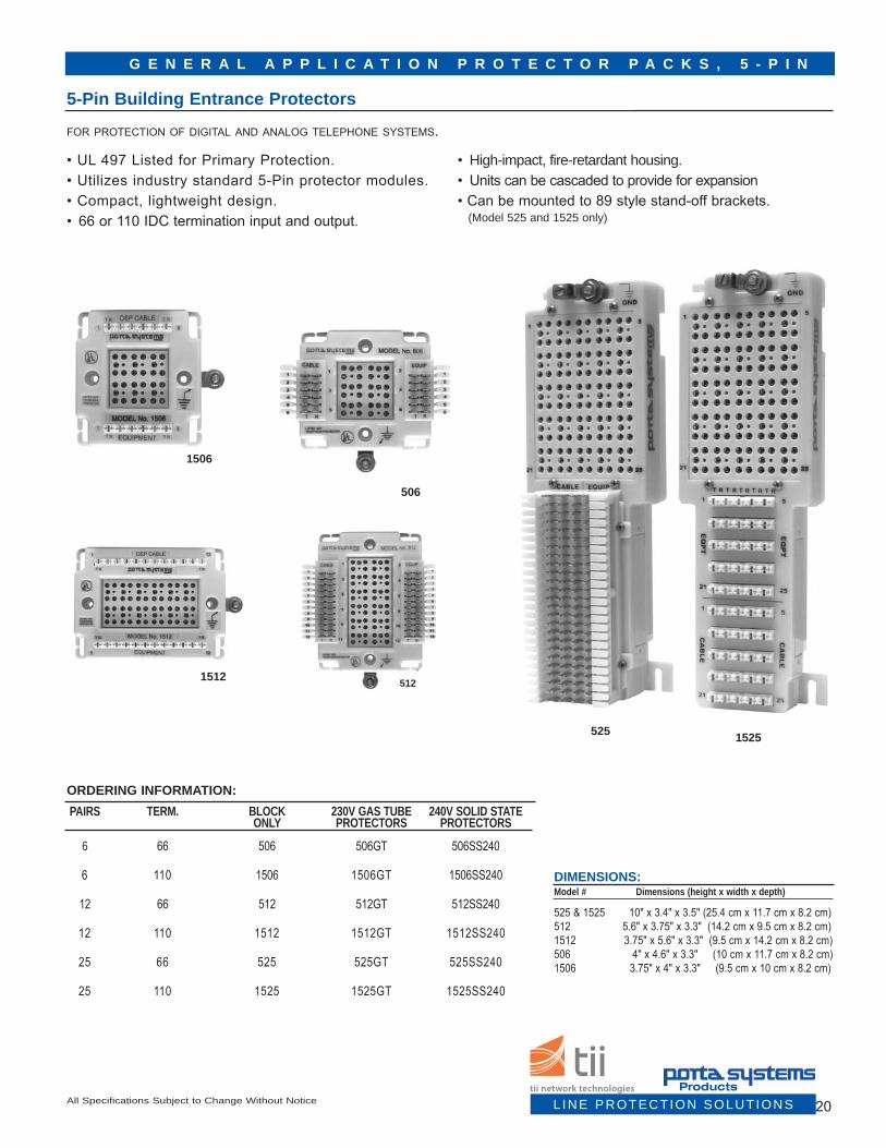
ORDERING INFORMATION: PAIRS TERM. BLOCK 230V GAS TUBE 240V SOLID STATE ONLY PROTECTORS PROTECTORS
6 66 506 506GT 506SS240 6 110 1506 1506GT 1506SS240 12 66 512 512GT 512SS240
12 110 1512 1512GT 1512SS240
25 66 525 525GT 525SS240
25 110 1525 1525GT 1525SS240
5121512
20All Specifications Subject to Change Without Notice
DIMENSIONS: Model # Dimensions (height x width x depth)
525 & 1525 10" x 3.4" x 3.5" (25.4 cm x 11.7 cm x 8.2 cm)512 5.6" x 3.75" x 3.3" (14.2 cm x 9.5 cm x 8.2 cm)1512 3.75" x 5.6" x 3.3" (9.5 cm x 14.2 cm x 8.2 cm)506 4" x 4.6" x 3.3" (10 cm x 11.7 cm x 8.2 cm)1506 3.75" x 4" x 3.3" (9.5 cm x 10 cm x 8.2 cm)
G E N E R A L A P P L I C A T I O N P R O T E C T O R P A C K S , 5 - P I N
5-Pin Building Entrance Protectors
1506
506
525 1525
for protection of digital and analog telephone systems.
• UL 497 Listed for Primary Protection.• Utilizes industry standard 5-Pin protector modules.• Compact, lightweight design.• 66 or 110 IDC termination input and output.
• High-impact, fire-retardant housing. • Units can be cascaded to provide for expansion• Can be mounted to 89 style stand-off brackets. (Model 525 and 1525 only)
L INE PROTECTION SOLUTIONSProducts

P O W E R F A I L T R A N S F E R U N I T
ORDERING INFORMATION: 578 LINEBACKER
MODEL DESCRIPTION578PFTU 8 circuit equipped with both 66 and RJ21 termination can be wired for either automatic loop-start or ground-start capability
provides emergency telephone service in the event of a power outage or system failure.
• Automatically activates, connecting eight pre-assigned “critical use” phone lines directly to Central Office trunks. • Automatically returns circuits to PBX/KSU when power is restored.• Can be cascaded to increase the number of critical use phone lines.
578 Linebacker
21 • Customer Service • 888.844.4720 • www.tiinetworktechnologies.com
General Application 504, and 581 Protector Packs, 1-Pinfor termination and protection of digital and analog telephone systems.
• The units can be cascaded to accommodate immediate system requirements as well as future growth.• Protector Packs feature a sturdy, flame-retardant housing and are factory loaded with 6, 10, or 25 gas tube.
504 PROTECTOR PACKS FACTORY INSTALLED PROTECTORS NUMBER TERM. OF BLOCK GAS TUBE PROTECTORS ONLY 230V
6 66 504PX2 504PX26GT
10 66 504PX210GT
6 110 1504PX2 1504PX26GT
10 110 1504PX210GT
581 PROTECTOR PACKS FACTORY INSTALLED PROTECTORS NUMBER TERM. OF BLOCK GAS TUBE PROTECTORS ONLY 230V
25 66 581P2 581P225GT
25 110 1581P2 1581P225GT
DIMENSIONS: Model # Dimensions (height x width x depth)
504 & 1504 5" x 4" x 3.5" (12.7 cm x 10.2 cm x 8.9 cm)581 & 1581 10" x 3.5" x 3" (25.4 cm x 8.9 cm x 7.6 cm) 581P225GT
504PX210GT
C E N T R A L O F F I C E P R O T E C T O R B L O C K
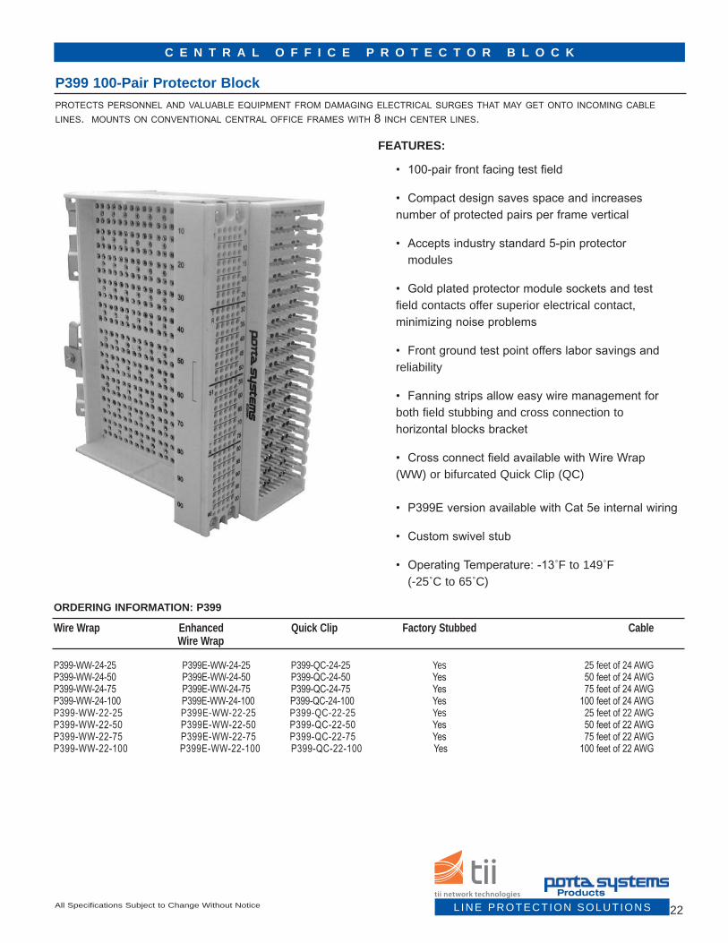
P399 100-Pair Protector Blockprotects personnel and valuable equipment from damaging electrical surges that may get onto incoming cable lines. mounts on conventional central office frames with 8 inch center lines.
ORDERING INFORMATION: P399
Wire Wrap Enhanced Quick Clip Factory Stubbed Cable Wire Wrap
P399-WW-24-25 P399E-WW-24-25 P399-QC-24-25 Yes 25 feet of 24 AWGP399-WW-24-50 P399E-WW-24-50 P399-QC-24-50 Yes 50 feet of 24 AWGP399-WW-24-75 P399E-WW-24-75 P399-QC-24-75 Yes 75 feet of 24 AWGP399-WW-24-100 P399E-WW-24-100 P399-QC-24-100 Yes 100 feet of 24 AWGP399-WW-22-25 P399E-WW-22-25 P399-QC-22-25 Yes 25 feet of 22 AWG P399-WW-22-50 P399E-WW-22-50 P399-QC-22-50 Yes 50 feet of 22 AWGP399-WW-22-75 P399E-WW-22-75 P399-QC-22-75 Yes 75 feet of 22 AWGP399-WW-22-100 P399E-WW-22-100 P399-QC-22-100 Yes 100 feet of 22 AWG
FEATURES:
• 100-pair front facing test field
• Compact design saves space and increases number of protected pairs per frame vertical
• Accepts industry standard 5-pin protector modules
• Gold plated protector module sockets and test field contacts offer superior electrical contact, minimizing noise problems
• Front ground test point offers labor savings and reliability
• Fanning strips allow easy wire management for both field stubbing and cross connection to horizontal blocks bracket
• Cross connect field available with Wire Wrap (WW) or bifurcated Quick Clip (QC)
• P399E version available with Cat 5e internal wiring
• Custom swivel stub
• Operating Temperature: -13˚F to 149˚F (-25˚C to 65˚C)
22All Specifications Subject to Change Without Notice L INE PROTECTION SOLUTIONSProducts

DIMENSIONS:H x W x D (Approx.)8.5” x 4.5” x 7.5” (21.6 cm x 11.4 cm x 19.1 cm)
4.5." MAX7.5"
C E N T R A L O F F I C E P R O T E C T O R B L O C K
P399 100-Pair Protector Block (cont'd)
8.5"
8.5"
the p399 is a compact 100-pair connector that utilizes industry standard 5-pin protector modules.
23 • Customer Service • 888.844.4720 • www.tiinetworktechnologies.com
C E N T R A L O F F I C E P R O T E C T O R B L O C K
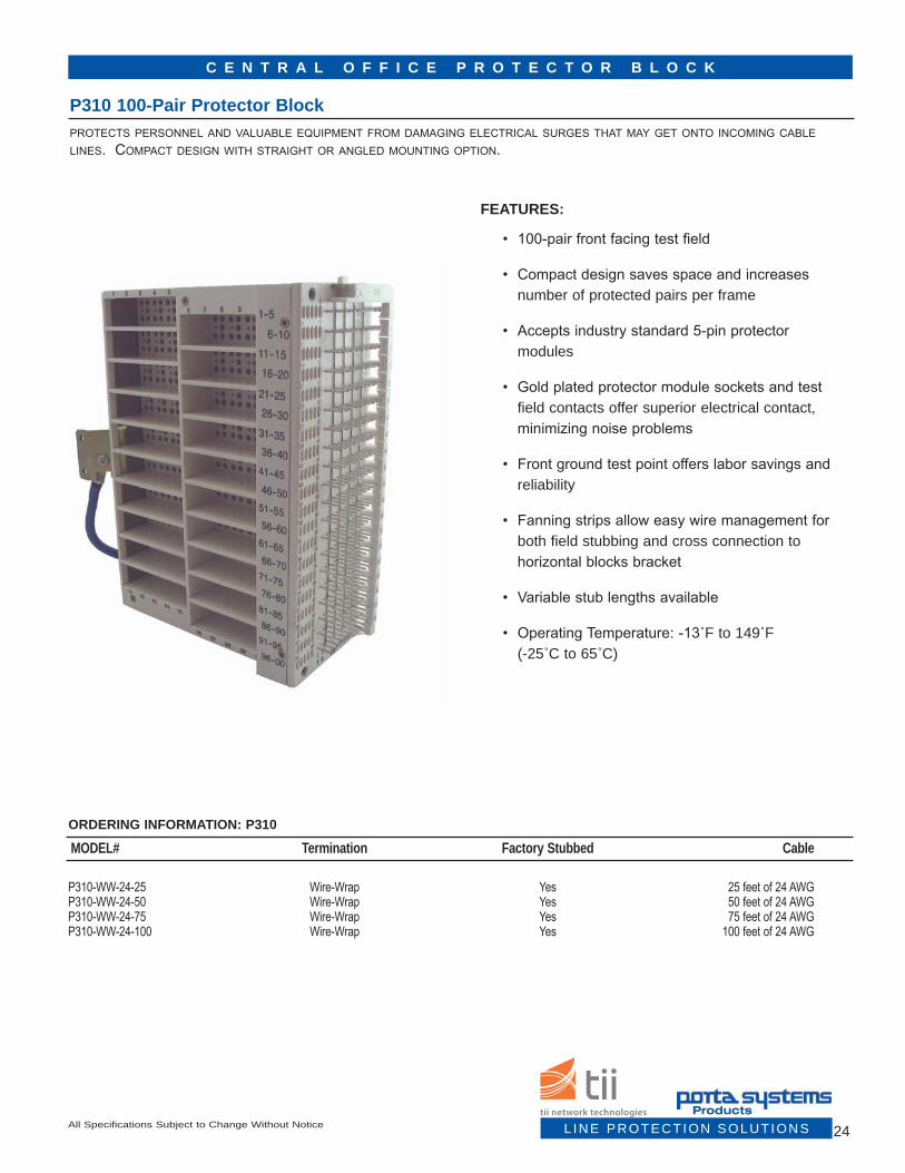
P310 100-Pair Protector Blockprotects personnel and valuable equipment from damaging electrical surges that may get onto incoming cable lines. compact design with straight or angled mounting option.
ORDERING INFORMATION: P310
MODEL# Termination Factory Stubbed Cable
P310-WW-24-25 Wire-Wrap Yes 25 feet of 24 AWGP310-WW-24-50 Wire-Wrap Yes 50 feet of 24 AWGP310-WW-24-75 Wire-Wrap Yes 75 feet of 24 AWGP310-WW-24-100 Wire-Wrap Yes 100 feet of 24 AWG
FEATURES:
• 100-pair front facing test field
• Compact design saves space and increases number of protected pairs per frame
• Accepts industry standard 5-pin protector modules
• Gold plated protector module sockets and test field contacts offer superior electrical contact, minimizing noise problems
• Front ground test point offers labor savings and reliability
• Fanning strips allow easy wire management for both field stubbing and cross connection to horizontal blocks bracket
• Variable stub lengths available
• Operating Temperature: -13˚F to 149˚F (-25˚C to 65˚C)
24All Specifications Subject to Change Without Notice L INE PROTECTION SOLUTIONSProducts

DIMENSIONS:H x W x D (Approx.)9.3” x 3.5” x 10” (23.7 cm x 8.9 cm x 25.4 cm)
C E N T R A L O F F I C E P R O T E C T O R B L O C K
P310 100-Protector Block (cont'd)the p310 is a compact 100-pair connector that utilizes industry standard 5-pin protector modules.
10"
9.3"
3.5"
25 • Customer Service • 888.844.4720 • www.tiinetworktechnologies.com

D I S T R I B U T I O N F R A M E E Q U I P M E N T
Model 88 Terminal Block Family - Front Facing General Purpose, High Density88 equipment terminal blocks are used to terminate the eXchange equipment pairs on the horizontal side of a conventional main distribution frame (mdf), and provide the cross-connect field for jumpering to the outside plant (osp) vertical side of the frame for protection of telephone systems.
Model 88 Terminal Block - Non-Connectorized
ORDERING INFORMATION: Model Pair Count Wire Wrap Pin Type Permanent Cable Connection 88-96 96 Single Wire Wrap 88-100 100 Single Wire Wrap 88-128 128 Single Wire Wrap 88-150 150 Single Wire Wrap 88-192 192 Single Wire Wrap 88-200 200 Single Wire Wrap 88-256 256 Single Wire Wrap 88B-96 96 Bifurcated Wire Wrap 88B-100 100 Bifurcated Wire Wrap 88B-128 128 Bifurcated Wire Wrap
• 8" block accommodates most conventional horizontal frame mounting configurations• Bifurcated wire wrap pins for the cross-connect field are available as "88B"• Hinged connection field facilitates easy termination of equipment pairs• Ample designation areas on both front and back of cover
• 8 mounting holes allow mounting on most any conventional frame • Wire Wrap terminations for equipment (input) and cross- connect (output) as per Telcordia specifications• RJ21 inputs on "C" models (88/96C, etc) • Face of the block is set at an angle to allow easy termination with wire wrap gun• Designation label included
88/256CP
DIMENSIONS: Pair Count Dimensions (height x width x depth) Weight
96-256 4.1" x 7.04" x 3.5" (10.4 cm x 17.9 cm x 8.9 cm) 3.3 lbs
Model 88C Terminal Block - Connectorized
ORDERING INFORMATION: Model # Model # Pair Count Wire Wrap Pin Type Permanent Cable Connection 88-96CM 88-96CF 96 Single Male or Female 64 pin Champ 88-100CM 88-100CF 100 Single Male or Female RJ21 88-128CM 88-128CF 128 Single Male or Female 64 pin Champ 88-150CM 88-150CF 150 Single Male or Female RJ21 88-192CM 88-192CF 192 Single Male or Female 64 pin Champ 88-200CM 88-200CF 200 Single Male or Female RJ21 88-256CM 88-256CF 256 Single Male or Female 64 pin Champ 88B-96CM 88B-96CF 96 Bifurcated Male or Female 64 pin Champ 88B-100CM 88B-100CF 100 Bifurcated Male or Female RJ21 88B-128CM 88B-128CF 96 Bifurcated Male or Female 64 pin Champ
DIMENSIONS: Pair Count Dimensions (height x width x depth) Weight
96-256 7.94" x 3.5" x 8.16" (20.2 cm x 8.9 cm x 20.7 cm) 3.8 lbs
26All Specifications Subject to Change Without Notice L INE PROTECTION SOLUTIONSProducts

O S P P R O T E C T O R B L O C K
P307 100-Pair Protector Blockporta systems p307 vdsl connector block is a powerful solution for protecting outside plant cables for voice, data, and video signals. our designs are aimed to give you the space savings and improved economy you are looking for. the front face of the p307 vdsl connector block has room for 100 industry standard 5-pin plug in protec-tor units arranged in a 10 X 10 configuration.
ORDERING INFORMATION: P399
MODEL# Pair Count Input Output
P307-A 100 Wire Wrap Wire WrapP307-BA40-A 100 40 ft. Cat 5e Stub Wire WrapP307-CA(XX)-MA(XX) 100 (XX) ft MS2 Connectorized (XX) ft RJ21 Conectorized Cat 5e Cable Cat 5e CableP307-EA(XX)-MA(XX) 100 (XX) ft 710 Connectorized (XX) ft RJ21 Connectorized Cat 5e Cable Cat 5e Cable
FEATURES:
• UL 497 and UL 497A listed for primary andsecondary protection
• Outside plant side of connector is typically wired with four 24 AWG CAT5e cable stubs
• VDSL compatible
• Compact, lightweight design
• Designed for use in integrated cabinets anddistribution frames
• Gold plated contacts
• Clearly marked protector positions
• Customized input and output options available
• Operating Temperature: -40˚F to 185˚F(-40˚C to 85˚C)
• TL9000 registered facility
27 • Customer Service • 888.844.4720 • www.tiinetworktechnologies.com

O S P P R O T E C T O R B L O C K
P307 100-Pair Protector Block (cont'd)
28All Specifications Subject to Change Without Notice
the p307 is a compact 100-pair connector that utilizes industry standard 5-pin protector modules.
DIMENSIONS:H x W x D (Approx.)8” x 6” x 0.5” (20.3 cm x 15.2 cm x 1.3 cm)
L INE PROTECTION SOLUTIONSProducts

O S P P R O T E C T O R P A N E L S
Rackmount Protector Panelsporta systems 19”, rj45-connect protector panels are a powerful solution for your connection or protec-tion application. our designs are aimed to give you the space savings and improved economy you are looking for. modern day broadband (triple play) networks require custom high-density connection and protection solutions with low cross talk and insertion loss. porta has the fleXible solution that meets these challenging requirements.
ORDERING INFORMATION: P399
MODEL# Pair Count Termination (In) Termination (Out)
19016-BA30-WA06 16 30 ft Stub Tail RJ45 - 6 ft Tail19032-BA30-WA06 32 30 ft Stub Tail RJ45 - 6 ft Tail
FEATURES:
• Designed to meet or exceed GR937 performancerequirements
• RJ45 output tail with custom lengths available
• Available with CAT5 wiring
• Low cross talk and insertion loss
• Compact, lightweight design
• Designed for use in OSP cabinets
• Available in a variety of input configurations(710, MS2, RJ21)
• Operating Temperature: -13˚F to 149˚F(-25˚C to 65˚C)
• ISO 9001:2000 registered facility
29 • Customer Service • 888.844.4720 • www.tiinetworktechnologies.com
Please contact Customer Service for custom cable lengths.
DIMENSIONS:H x W x D (Approx.)8” x 6” x 0.5” (20.3 cm x 15.2 cm x 1.3 cm)

O S P P R O T E C T O R P A N E L S
Rackmount Protector Panelsporta systems 19”, 66-connect protector panels are a powerful solution for your connection or protection appli-cation. our designs are aimed to give you the space savings and improved economy you are looking for. modern day broadband (triple play) networks require custom high-density connection and protection solutions with low cross talk and insertion loss. porta has the fleXible solution that meets these challenging requirements.
ORDERING INFORMATION: P399 MODEL# Pair Count Termination (In) Termination (Out)
19050-CC04-66 50 MS2 - 4 ft Tail 6619050-EC04-66 50 710 - 4 ft Tail 6619050-MC04-66 50 RJ - 4 ft Tail 66
FEATURES:
• Designed to meet or exceed GR937 performancerequirements
• 66 block output cross-connect termination
• Available with CAT5 wiring
• Low cross talk and insertion loss
• Compact, lightweight design
• Designed for use in OSP cabinets
• Available in a variety of input configurations(710, MS2, RJ21)
• Operating Temperature: -13˚F to 149˚F(-25˚C to 65˚C)
• ISO 9001:2000 registered facility
Please contact Customer Service for custom cable lengths.
DIMENSIONS:H x W (Approx.)3.5” x 19” (8.9 cm x 48.3 cm)
30All Specifications Subject to Change Without NoticeL INE PROTECTION SOLUTIONS
Products

O S P P R O T E C T O R P A N E L S
Rackmount Protector Panelsporta systems 110-connect protector panels are a powerful solution for your connection or protection applica-tion. our designs are aimed to give you the space savings and improved economy you are looking for. modern day broadband (triple play) networks require custom high-density connection and protection solutions with low cross talk and insertion loss. porta has the fleXible solution that meets these challenging requirements.
ORDERING INFORMATION: P399 MODEL# Pair Count Termination (In) Termination (Out)
19050-CC04-110 50 MS2 - 4 ft Tail 11019050-EC04-110 50 710 - 4 ft Tail 11019050-MC04-110 50 RJ - 4 ft Tail 11019050-110-110 50 110 110
FEATURES:
• Designed to meet or exceed GR937 performancerequirements
• Available with CAT5 wiring
• Low cross talk and insertion loss
• Compact, lightweight design
• Designed for use in OSP cabinets
• Available in a variety of input and outputconfigurations (710, RJ21, 66, 110, MS2)
• Operating Temperature: -13˚F to 149˚F(-25˚C to 65˚C)
• ISO 9001:2000 registered facility
• 110 Output cross-connect termination
31 • Customer Service • 888.844.4720 • www.tiinetworktechnologies.com
DIMENSIONS:H x W x D (Approx.)3.5” x 19” x 5.3" (8.9 cm x 48.3 cm x 13.5 cm)

O S P P R O T E C T O R P A N E L S
Rackmount Protector Panelsporta systems 19”, 100-pair protector panels are a powerful solution for your connection or protection applica-tion. our designs are aimed to give you the space savings and improved economy you are looking for. modern day broadband (triple play) networks require custom high-density connection and protection solutions with low cross talk and insertion loss. porta has the fleXible solution that meets these challenging requirements.
ORDERING INFORMATION: P399 MODEL# Pair Count Termination (In) Termination (Out)
19100-CC06-MC06 100 MS2 - 6 ft Tail RJ - 6 ft. Tail19100-EC06-MC06 100 710 - 6 ft Tail RJ - 6 ft. Tail19100-MC06-MC06 100 RJ - 6 ft Tail RJ - 6 ft. Tail
FEATURES:
• Designed to meet or exceed GR937 performancerequirements
• Available with CAT5 wiring
• Low cross talk and insertion loss
• Compact, lightweight design
• Designed for use in OSP cabinets
• Available in a variety of input and outputconfigurations (710, MS2, RJ21)
• Operating Temperature: -13˚F to 149˚F(-25˚C to 65˚C)
• ISO 9001:2000 registered facility
Please contact Customer Service for custom cable lengths.
32All Specifications Subject to Change Without Notice L INE PROTECTION SOLUTIONSProducts

O S P P R O T E C T O R P A N E L S
Rackmount Protector Panel (cont'd)
DIMENSIONS:H x W (Approx.)3.5” x 19” (8.9 cm x 48.3 cm)
REAR VIEW ROTATED 180º
36” +2”/-0Typical
2.19 REF.
3.47 REF.
2.13 REF.
36” +2”/-0Typical
Shown with RJ21 input and output
Other terminations
available19 REF.
33 • Customer Service • 888.844.4720 • www.tiinetworktechnologies.com

2.69” REF.
19” REF.
1.6” REF.
18 5/16” REF.
3” 3.47”
34All Specifications Subject to Change Without Notice
O S P P R O T E C T O R P A N E L S
Rackmount Protector Panelsporta systems 19”, 100-pair protector panels are a powerful solution for your connection or protection applica-tion. our designs are aimed to give you the space savings and improved economy you are looking for. modern day broadband (triple play) networks require custom high-density connection and protection solutions with low cross talk and insertion loss. porta has the fleXible solution that meets these challenging requirements.
ORDERING INFORMATION: P399 MODEL# Pair Count Termination (In) Termination (Out)
19110-CC06-MC06 100 MS2 - 6 ft Tail RJ - 6 ft. Tail19110-EC06-MC06 100 710 - 6 ft Tail RJ - 6 ft. Tail
FEATURES:
• Designed to meet or exceed GR937 performancerequirements
• 2U, 19” rackmount 100-pair 110 to 110 crossconnect panel (unprotected)
• Available with CAT5 wiring
• Low cross talk and insertion loss
• Compact, lightweight design
• Designed for use in OSP cabinets
• Available in a variety of input and outputconfigurations (710, RJ21, 66, 110, MS2)
• Operating Temperature: -13˚F to 149˚F(-25˚C to 65˚C)
• ISO 9001:2000 registered facility
Please contact Customer Service for custom cable lengths.
DIMENSIONS:H x W (Approx.)3.5” x 19” x 5.3" (8.9 cm x 48.3 cm x 13.5 cm)
L INE PROTECTION SOLUTIONSProducts

O S P P R O T E C T O R P A N E L S
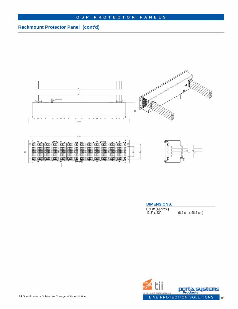
Rackmount Protector Panelsporta’s protector panels are a 3u, 200-pair protector panel designed for 23” racks. these protector panels are a powerful solution for your connection or protection application. our designs are aimed to give you the space savings and improved economy you are looking for. modern day broadband (triple play) networks require custom high-density connection and protection solutions with low cross talk and insertion loss. porta has the fleXible solution that meets these challenging requirements.
ORDERING INFORMATION: P399 MODEL# Pair Count Termination (In) Termination (Out)
23200-CC06-MC06 200 MS2 - 6 ft Tail RJ - 6 ft. Tail23200-EC06-MC06 200 710 - 6 ft Tail RJ - 6 ft. Tail23200-MC06-MC06 200 RJ - 6 ft Tail RJ - 6 ft. Tail
FEATURES:
• 3U, 23” Rackmount 200-pair Protector Panel
• Designed to meet or exceed GR937 performancerequirements
• Available with CAT5 wiring
• Low cross talk and insertion loss
• Compact, lightweight design
• Designed for use in OSP cabinets
• Available in a variety of input and output cableconfigurations (710, RJ21, MS2)
• Operating Temperature: -13˚F to 149˚F(-25˚C to 65˚C)
• ISO 9001:2000 registered facility
35 • Customer Service • 888.844.4720 • www.tiinetworktechnologies.com
Please contact Customer Service for custom cable lengths.
O S P P R O T E C T O R P A N E L S
Rackmount Protector Panel (cont'd)
36All Specifications Subject to Change Without Notice
DIMENSIONS:H x W (Approx.)13.3" x 23" (8.9 cm x 58.4 cm)
L INE PROTECTION SOLUTIONSProducts
37 • Customer Service • 888.844.4720 • www.tiinetworktechnologies.com
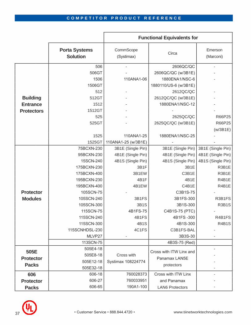
C O M P E T I T O R P R O D U C T R E F E R E N C E
Functional Equivalents for
Porta Systems Solution
CommScope(Systimax)
CircaEmerson(Marconi)
Building Entrance
Protectors
506 - 2606QC/QC -506GT - 2606QC/QC (w/3B1E) -
1506 110ANA1-06 1880ENA1/NSC-6 -1506GT 1880110/US-6 (w/3B1E)
512 - 2612QC/QC -512GT - 2612QC/QC (w/3B1E) -
1512 - 1880ENA1/NSC-12 -1512GT - - -
525 - 2625QC/QC R66P25525GT - 2625QC/QC (w/3B1E) R66P25
(w/3B1E)1525 110ANA1-25 1880ENA1/NSC-25 -
1525GT 110ANA1-25 (w/3B1E) - -
ProtectorModules
75BCXN-230 3B1E (Single Pin) 3B1E (Single Pin) 3B1E (Single Pin)95BCXN-230 4B1E (Single Pin) 4B1E (Single Pin) 4B1E (Single Pin)
15SCN-240 4B1S (Single Pin) 4B1S (Single Pin) 4B1S (Single Pin)175BCXN-230 3B1F 3B1E R3B1E175BCXN-400 3B1EW C3B1E R3B1E195BCXN-230 4B1F 4B1E R4B1E195BCXN-400 4B1EW C4B1E R4B1E
105SCN-75 - C3B1S-75 -105SCN-240 3B1FS 3B1FS-300 R3B1FS105SCN-300 3B1S 3B1S-300 R3B1S
115SCN-75 4B1FS-75 C4B1S-75 (PTC) -115SCN-240 4B1FS 4B1FS -300 R4B1FS115SCN-300 4B1S 4B1S-300 R4B1S
115SCNHDSL-230 4C1FS C3B1FS-BAL -MLVP27 - 3B3S-30 -
113SCN-75 4B3S-75 (Red)
505E Protector
Packs
505E4-18Cross with
Systimax 108224774
Cross with ITW Linx and Panamax LAN5E
protectors
-505E8-18 -
505E12-18 -505E32-18 -
606 Protector
Packs
606-18 760028373 Cross with ITW Linx and Panamax
LAN6 Protectors
-606-27 760033951 -606-65 190A1-100 -

Functional Equivalents for
Porta Systems Building Entrance Terminal
(BET) Solution
CommScope(Systimax)
CircaEmerson(Marconi)
PairCount
100
26100-ST-MST 190A1-100 1900A1-100 -25100-110-M110C - 1880ENA1/NSC-100 BEPNCT100T
25100-66-M66C - 1890ECT1/NSC-100 BEPNCC100C25100-ST-M110C 489ACC1-100 1880B1-100 BEPT100SC2525100-ST-M66C 489BCC1-100 1890BC1-100 BEPC100SC2526100-ST-MST 190A1-100 1900A1-100 R13410012
24100-110-M110C 489ACA1-100 1880ECA1-100 BEPT100T24100-66-M66C 489BCB1-100 1890ECT1-100 BEPC100C
50
25050-110-M110C - 1880ENA1/NSC-50 BEPNCT50T25050-66-M66C - 1890ECT1/NSC-50 BEPNCC50C
25050-ST-M110C 489ACC1-050 1880B1-50 BEPT50SC2525050-ST-M66C 489BCC1-050 1890BC1-50 BEPC50SC25
26050-ST-MST 190A1-50 - R13450624050-110-M110C 489ACA1-050 1880ECA1-50 BEPT50T
24050-66-M66C 489BCB1-050 1890ECT1-50 BEPC50C
25
25025-110-M110C - 1880ENA1/NSC-25G BEPNCT25T25025-66-M66C - 1890ECT1/NSC-25 BEPNCC25C
25025-ST-M110C 489ACC1-025 1880B1-25 BEPT25SC2525025-ST-M66C 489BCC1-025 1890BC1-25 BEPC25SC25
26025-ST-MST - - -24025-110-M110C 489ACA1-025 1880ECA1-25 BEPT25T
24025-66-M66C 489BCB1-025 1890ECT1-25 BEPC25C
1. Add a "P" before the "C" of any BET part number to have the BET factory loaded with 230-volt Gas tube protectors (3B1E equivalents). For Example: 24100-110-M110PC.
2. Custom BET configurations and specialty products such as 710 and MS2 inputs and CAT 5E and CAT 6 entrance protectors are available. For Tii-Porta customer service at 888.8444720 or your local manufacturer's representative for assistance.
C O M P E T I T O R P R O D U C T R E F E R E N C E
38All Specifications Subject to Change Without Notice L INE PROTECTION SOLUTIONSProducts

• 141 RODEO DRIVE • EDGEWOOD, NY 17717 • • 888.844.4720 • 1-631-789-5000 • FAX 1-631-789-5063 •
www.tiinetworktechnologies.com
Products
Tii Network Technologies, Inc.Registered to TL 9001:2008Certificate No. 10002234 TL