commande par la méthode de lyapunov - accueil · web view... “speed-sensorless...
TRANSCRIPT

A PI/Backstepping Approachfor Induction Motor Drives Robust Control
O. Benzineb1,2, H. Salhi3, M. Tadjine2, M.S. Boucherit2, M.E.H Benbouzid1
Abstract–This paper presents a robust control design procedure for induction motor drives in case of modeling errors and unknown load torque. The control law is based on the combination of nonlinear PI controllers and a backstepping methodology. More precisely, the controllers are determined by imposing flux-speed tracking in two steps and by using appropriate PI gains that are nonlinear functions of the system state. A comparative study between the proposed PI/Backstepping approach and the feedback linearizing control is made by realistic simulations including load torque changes, parameter variations and measurement noises. Flux-speed tracking results show the proposed method effectiveness in presence of strong disturbances.
Keywords: Nonlinear PI control, backstepping, induction motor, robustness, flux-speed tracking, feedback linearizing control.
I. IntroductionThe development of induction motor drives has
considerably accelerated in order to satisfy the increasing need of various industrial applications in low and medium power range. Indeed, induction motors have simple structure, high efficiency and increased torque/inertia ratio. However, their dynamical model is nonlinear, multivariable, coupled, and is subject to parameter uncertainties since the physical parameters are time-variant. The design of robust controllers becomes then a relevant challenge [1-2].
Induction motor drives control has been an active research domain over the last years. Different control techniques such as Field-Oriented control (FOC), feedback linearization control, sliding mode control passivity approach, and adaptive control have been reported in the literature [3]. The FOC ensures partial decoupling of the plant model using a suitable transformation and then PI controllers are used for tracking regulation errors. The high performance of such strategy may be deteriorated in practice due to plant uncertainties [4-5]. Exact input-output feedback linearization of induction motors model can be obtained using tools from differential geometry. This method cancels the nonlinear terms in the plant model which fails when the physical parameters varies [6-7]. By contrast, passivity-based control does not cancel all the nonlinearities but enforce them to be passive, i.e. dissipating energy and hence ensuring tracking regime [8-10]. Sliding Mode Control (SMC) is widely applied because of its easiness and attractive robustness properties [11-12]. On the other hand, SMC exhibits high-gain when the controlled system is subject to large
parameter variations. This however limits the application of such control scheme. To overcome this problem, many authors have proposed sliding mode and adaptive control combined structure. This leads to reduced gain and robustness against matched and unmatched uncertainties [13-15]. Adaptive backstepping is also used for speed control to compensate the uncertainties that remains after input-output linearization [16-20]. Fuzzy logic and neural networks are also applied. Several control schemes have been developed. The main feature of such techniques is their intrinsic robustness properties as they do not require the plant model precise knowledge [21-24]. These approaches may introduce some time constraints in real-time applications.
Otherwise, the conventional PI controllers are the most common algorithms used in industry today. Their attractiveness is due to their structure simplicity and the industrial operators acquaintance with them. Several PI controllers have been proposed in the literature for linear and nonlinear processes [5], [25]. Nevertheless, PI controllers fundamental deficiency is the lack of asymptotic stability and robustness proofs for a given nonlinear system.
Therefore, this paper proposes to deal with this deficiency by proposing a robust nonlinear PI controller for an induction motor drive with unknown load torque. The controller is derived by combining a backstepping procedure with a PI structure. More precisely, the controllers are determined by imposing the current-speed tracking recursively in two steps and by using appropriate gains that are nonlinear functions of the system state.

II. Problem Formulation2.1 Nomenclature
s, (r) = Stator (rotor) index;, = Synchronous reference frame index;ref = Reference index;v (i) = Voltage (Current);, = Flux;r = Load torque;R = Resistance;L (M) = Inductance (Mutual inductance); = Leakage coefficient;Ts (Tr) = Stator (rotor) circuit time constant.ωr (ωs) = Rotor speed (Synchronous speed);kf = Friction coefficient;J = Rotor Inertia;p = Pole pair number.
2.2 Induction Motor Model
In the stator reference frame, the state-space model of voltage-fed induction motor is derived from the Park model. The state vector is composed of the stator current components (i,i), rotor flux components (,) and rotor rotating pulsation r, whereas a vector control is composed of the stator voltage components (v,v) and the external disturbance is represented by the load torque r [1], [3].
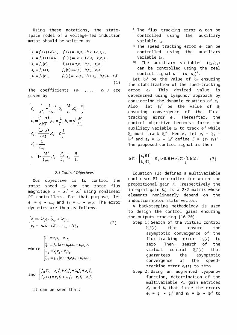
Using these notations, the state-space model of a voltage-fed induction motor should be written as
(1)
The coefficients (a1 ,..., c5 ) are given by
2.3 Control Objectives
Our objective is to control the rotor speed r and the rotor flux magnitude = x3
2 + x42 using nonlinear PI
controllers. For that purpose, let e1 = – ref and e2 = – ref. The error dynamics are then as follows.
(2)
where
and
It can be seen that:i. The flux tracking error e1 can be controlled using
the auxiliary variable 1.ii. The speed tracking error e2 can be controlled using
the auxiliary variable 2.iii.The auxiliary variables (1,2) can be controlled
using the real control signal u = (u1 u2)T.Let 2
d be the value of 2 ensuring the stabilization of the sped-tracking error e2. This desired value is determined using Lyapunov approach by considering the dynamic equation of e2. Also, let 1
d be the value of 1 ensuring convergence of the flux-tracking error e1. Thereafter, the control objective becomes: force the auxiliary variable 1 to track 1
d while 2 must track 2d.
Hence, let e3 = 1 – 1d and e4 = 2 – 2
d define E = (e3
e4)T. The proposed control signal is then
(3)
Equation (3) defines a multivariable nonlinear PI controller for which the proportional gain Kp
(respectively the integral gain Ki) is a 2×2 matrix whose elements nonlinearly depend on the induction motor state vector.
A backstepping methodology is used to design the control gains ensuring the outputs tracking [16-20].
Step 1: Search of the virtual control 1d(t) that ensure
the asymptotic convergence of the flux-tracking error e1(t) to zero. Then, search of the virtual control 2
d(t) that guarantees the asymptotic convergence of the speed-tracking error e2(t) to zero.
Step 2: Using an augmented Lyapunov function, determination of the multivariable PI gain matrices Kp and Ki that force the errors e3 = 1 – 1
d and e4 = 2 – 2d to converge to zero
leading to flux (e1) and speed (e2) tracking errors exponential convergence.
III. Nonlinear PI-Based Backstepping Control Design
Let us first derive the auxiliary variables ensuring flux-speed tracking. One has the following result.
Proposition 1: Consider the dynamic (2). Then flux and speed tracking errors e1(t) and e2(t) are exponentially stable provided that
(4)
Proof: Consider the following Lyapunov function related to the flux dynamic defined in (2).
(5)
Its time-derivative is expressed by
(6)
If the virtual control laws 1 and 2 are forced to take the desired value given by (4), the Lyapunov function time-derivative takes the following final form.
(7)
Provided that (8)It implies that e1 and e2 are exponentially stable. End of Proof
Remark 1: Even if the load r torque is unknown, one can always ensure speed-tracking due to (8). Moreover, (8) can also cope with modeling errors and parametric variations in the speed dynamical equation.
The real control signal u = (u1 u2)T, that force the errors e3 = 1 – 1
d and e4 = 2 – 2d to converge to zero,
will be now derived. One needs the following definitions: Consider a real nonlinear function S(x) satisfying xS(x) > 0 x 0. Examples of such functions are S(x) = x2k + 1 (k positive integer), or S(x) = sinh(x), or S(x) = tanh(x), or S(x) = sign(x).
Let (9)
with K any positive definite matrix.
(10)
Where
(11)
One has the following result.
Proposition 2: Consider the induction motor dynamic (1) in closed-loop with the multivariable PI control (3), (9-1&). Assume that the gains 1 and 2 are such that
(12)
Then, the following properties are verified.i. The tracking errors e1(t), e2(t), e3(t), and e4(t) are
exponentially stable.ii. The closed-loop system is internally stable.
Proof: Consider the augmented Lyapunov function.
(13)
Its time derivative is given by(14)
Recalling that
this gives (15)
Replacing the dynamics of E by
and the control signal by (3)
then one have(16)

where
If v(t) < 0 then
In this case, one concludes that property i is verified. Notice that
(17)
Since the terms ziS(zi); I = 1, 2, are always positive, v(t) is negative provided the gains I and 2 are such that inequalities (12) are satisfied.
The convergence of the output tracking error ei (i = 1, 2, 3, 4) to zero does not implies that the state vector x = [x1 x2 x3 x4]T of the induction motor remains bounded. However, since e2 = x5 – ref and e1 = x3
2 + x42 + ref are
exponentially stable with ref and ref bounded. Therefore, one concludes that the states x3, x4 and x5 are all-time bounded. Let = (x1 x2)T and = (x3 x4 x5)T. The state has already been proven to be bounded. From (1), it can be seen that since a1 is positive, the origin of the subsystem is stable for any fixed value d of the vector . One can therefore conclude that the state is bounded. End of Proof
Remark 2: In order to compute the boundaries , load torque and functions fi exact knowledge is not needed. Bounds can be used on these variables. In this case, the proposed control law is still valid in presence of parametric uncertainties that corrupt the system dynamics.
Remark 3: The PI gains developed in proposition 2 are nonlinear and may be time-variant. Further, the integral gains must be sufficiently large to fulfill constraints (12). The proportional gains define the slope of the closed-loop system dynamics and they may be time-variant.
IV. Comparative Study
In this section, a comparison is carried-out between the proposed PI/Backstepping control approach with the well-known feedback linearizing control (FLC), which is generally used for decoupling and linearizing nonlinear systems [6-7]. In brief, the induction motor model is written in the following form.
(18)
Then, the output variables are differentiated with respect to time until at least one of the inputs appears. This can be easily done by using the Lie derivative of a state function h(X) along a vector field f(X) defined by
(19)
Considering the induction motor model (1) and using the approach developed in [7], the resulting control signal ensuring feedback linearization is given by
(20)
where (21)
is an auxiliary control signal used to stabilize the resulting linear system. The gains ki are designed by pole placement of the error dynamics. Notice that this method cancels the nonlinear terms in the plant model.
The simulated induction motor ratings are given in the Appendix.
The PI gains are chosen as indicated in Proposition 2. They are adjusted till satisfactory results are obtained. S(z) functions are taken as follows
(22)
with = 0.01. The following PI gains have been used for all the simulated situations.
For the feedback linearization control simulations, the gains are chosen as follows.

To test the proposed PI/Backstepping control approach, three typical situations have been simulated.
4.1 Test 1 – Ideal Case
Speed and flux tracking are checked for no load torque and no parameter variations case. Simulation results are illustrated by Figs. 1 and 2 for PI/Backstepping control and feedback linearizing control, respectively. It can be noticed that both control approaches ensure good current and speed tracking. However, the feedback linearizing control is advantageous since it allows decoupling between flux and speed dynamics, which is not the case of the proposed approach.
4.2 Test 2 – Unknown Load Torque
Speed and flux tracking are now checked in the case of an unknown load torque (r = 3nom) applied between t = 2sec and t = 4sec. The control performances are illustrated by Figs. 3 and 4. It can be noticed that feedback linearizing control fails to guarantee speed tracking. Conversely, PI/Backstepping control still guarantees it. This result is very interesting since in practice the load torque is unknown and time-variant.
4.3 Test 3 – Parameter Variations
For the PI/Backstepping control approach, simulations have been carried-out with 50% variation in all the parameters of (1) starting from t = 2sec till t = 4sec. The obtained results are very satisfactory and show strong robustness against parameter variations (Fig. 5).
In the same above simulation conditions, an unstable feedback loop is achieved for feedback linearizing control. For illustration, parameters a5 and b5 are varied and all the others are maintained constant. Even in this case, decoupling between speed and flux dynamics is lost and further speed tracking is very poor (Fig. 6).
V. ConclusionThis paper has presented a robust control design
procedure for induction motor drives in case of modeling errors and unknown load torque. The control law is based on the combination of nonlinear PI controllers and a backstepping approach. More precisely, the controllers are determined by imposing flux-speed tracking in two steps and by using appropriate PI gains that are nonlinear functions of the system state.
A comparative study between the proposed PI/Backstepping approach and the feedback linearizing control is made by realistic simulations including load torque changes, parameter variations and measurement
noises. Flux-speed tracking results show the proposed control approach effectiveness in presence of strong disturbances.
0 1 2 3 40
0.1
0.2
0.3
0.4
Time(s)
flux
(Wb)
0 1 2 3 4-20
-10
0
10
20
Time(s)
Ias
(A)
0 1 2 3 4-200
-100
0
100
200
Time(s)
wr(r
d/s)
0 1 2 3 4-400
-200
0
200
400
Time(s)
Vas
(V)
0 0.5 1 1.5 2 2.5 3 3.5 4-8
-6
-4
-2
0
2x 10⁻⁴
Time(s)flu
x er
ror
0 0.5 1 1.5 2 2.5 3 3.5 4-0.04
-0.02
0
0.02
0.04
Time(s)
spee
d er
ror
Fig. 1. PI/Backstepping control: Test 1.
0 1 2 3 40
0.1
0.2
0.3
0.4
Time(s)
flux
(Wb)
0 1 2 3 4-20
-10
0
10
20
Time(s)
Ias
(A)
0 1 2 3 4-400
-200
0
200
400
Time(s)
wr(r
d/s)
0 1 2 3 4-400
-200
0
200
400
Time(s)
Vas
(V)

0 0.5 1 1.5 2 2.5 3 3.5 4-5
-4
-3
-2
-1
0x 10-3
Time(s)
flux
erro
r
0 0.5 1 1.5 2 2.5 3 3.5 4-1
-0.5
0
0.5
1
Time(s)
spee
d er
ror
Fig. 2. Feedback linearizing control: Test 1.
0 1 2 3 40
0.1
0.2
0.3
0.4
Time(s)
flux
(Wb)
0 1 2 3 4-50
0
50
100
Time(s)
Ias
(A)
0 1 2 3 4-200
-100
0
100
200
Time(s)
wr(r
d/s)
0 1 2 3 4-500
0
500
Time(s)
Vas
(V)
0 0.5 1 1.5 2 2.5 3 3.5 4-1
0
1
2x 10⁻³
Time(s)
flux
erro
r
0 0.5 1 1.5 2 2.5 3 3.5 4-0.4
-0.3
-0.2
-0.1
0
0.1
Time(s)
spee
d er
ror
Fig. 3. PI/Backstepping control: Test 2.
0 1 2 3 40
0.1
0.2
0.3
0.4
Time(s)
flux
(Wb)
0 1 2 3 4-50
0
50
Time(s)
Ias
(A)
0 1 2 3 4-200
-100
0
100
200
300
Time(s)
wr(r
d/s)
0 1 2 3 4-500
0
500
Time(s)
Vas
(V)
0 0.5 1 1.5 2 2.5 3 3.5 4-6
-4
-2
0
2x 10⁻³
Time(s)
flux
erro
r
0 0.5 1 1.5 2 2.5 3 3.5 4-30
-20
-10
0
10
Time(s)
spee
d er
ror
Fig. 4. Feedback linearizing control: Test 2.
0 1 2 3 40
0.1
0.2
0.3
0.4
Time(s)
flux
(Wb)
0 1 2 3 4-20
-10
0
10
20
Time(s)
Ias
(A)
0 1 2 3 4-200
-100
0
100
200
Time(s)
wr(r
d/s)
0 1 2 3 4-400
-200
0
200
400
Time(s)
Vas
(V)
0 0.5 1 1.5 2 2.5 3 3.5 4-1
-0.5
0
0.5
1x 10⁻³
Time(s)
flux
erro
r
0 0.5 1 1.5 2 2.5 3 3.5 4-0.04
-0.02
0
0.02
0.04
Time(s)
spee
d er
ror
Fig. 5. PI/Backstepping: Test 3.
0 1 2 3 40
0.1
0.2
0.3
0.4
Time(s)
flux
(Wb)
0 1 2 3 4-20
-10
0
10
20
Time(s)
Ias
(A)
0 1 2 3 4-200
-100
0
100
200
300
Time(s)
wr(r
d/s)
0 1 2 3 4-400
-200
0
200
400
Time(s)
Vas
(V)

0 0.5 1 1.5 2 2.5 3 3.5 4-5
0
5
10
15
20x 10-3
Time(s)
flux
erro
r
0 0.5 1 1.5 2 2.5 3 3.5 4-40
-20
0
20
Time(s)
spee
d er
ror
Fig. 6. Feedback linearizing control: Test 3.
AppendixRated Data of the Simulated Induction Motor
4 kW, 23.8 Nm, 1500 rpm, p = 2Rs = 1.125 , Rr = 1.103 , Ls = 0.17 H, Lr = 0.015 H, M = 0.048 H
J = 0.135 kg.m², kf = 0.00182 Nm.s
References[1] P.C. Krause et al. Analysis of Electric Machinery and Drive
Systems. John Wiley & Sons: 2002.[2] P.V. Kokotovic et al. Nonlinear and Adaptive control. John Wiley
& Sons: 1995.[3] Leonhard W. Control of Electrical Drives. Springer-Verlag, 1996.[4] A. Behal et al., “An improved IFOC for the induction motor,”
IEEE Trans. Control Systems Technology, vol. 11, n°2, pp. 248-252, March 2003.
[5] D. Casadei et al., “FOC and DTC: two viable schemes for induction motors torque control,” IEEE Trans. Power Electronics, vol. 17, n°5, pp. 779-787, September 2002.
[6] J. Chiasson, “A new approach to dynamic feedback linearization control of an induction motor,” IEEE Trans. Automatic Control, vol. 42, n°3, pp. 391-397, March 1998.
[7] R. Marino et al., “Adaptive input-output linearizing control of induction motors,” IEEE Tran. Automatic Control, vol. 38, n°2, pp. 208-221, February 1993.
[8] G.W. Chang et al., “Tuning rules for the PI gains of field-oriented controllers of induction motors,” IEEE Trans. Industrial Electronics, vol. 47, n°3, pp. 592-602, June 2000.
[9] C. Cecati et al., “Torque and speed regulation of induction motors using passivity theory approach,” IEEE Tran. Industrial Electronics, vol. 46, n°1, pp. 23-36. February 1999.
[10] P.J. Nicklasson et al., “Passivity-based control of a class of Blondel-Park transformable electric machines,” IEEE Tran. Automatic Control, vol. 42, n°5, pp. 629-647. May 1997.
[11] M. Comanescu et al., “Decoupled current control of sensorless induction-motor drives by integral sliding mode,” IEEE Trans. Industrial Electronics, vol. 55, n°11, pp. 3836-3845, November 2008.
[12] A. Derdiyok, “Speed-sensorless control of induction motor using a continuous control approach of sliding-mode and flux observer,” IEEE Trans. Industrial Electronics, vol. 52, n°4, pp. 1170-1176, August 2005.
[13] S. Hasan et al., “A Luenberger–Sliding mode observer for online parameter estimation and adaptation in high-performance induction motor drives,” IEEE Trans. Industry Applications, vol. 45, n°2, pp. 772-781, March-April 2009.
[14] D. Traore et al., “Sensorless induction motor: High-order sliding-mode controller and adaptive interconnected observer,” IEEE Trans. Industrial Electronics, vol. 55, n°11, pp. 3818-3827, November 2008.
[15] M. Comanescu et al., “Sliding-mode MRAS speed estimators for sensorless vector control of induction machine,” IEEE Trans. Industrial Electronics, vol. 53, n°1, pp. 146-153, February 2006.
[16] A. Abbou et al., “Design of a new sensorless controller of induction motor using backstepping approach,” International Review of Electrical Engineering, vol. 4. n°3, pp. 174-181, February 2008.
[17] S. Chaouch et al., “Backstepping control design of sensorless speed induction motor based on MRAS technique,” International Review of Electrical Engineering, vol. 2. n°1, pp. 738-744, October 2007.
[18] M. Tadjine et al., “Robust backstepping vector control for the doubly fed induction motor,” IET Control Theory & Applications, vol. 1, n°4, pp. 861-868, July 2007.
[19] A. Ebrahim et al., “Adaptive backstepping control of an induction motor under time-varying load torque and rotor resistance uncertainty,” In Proceedings of the IEEE SSST’06, Cookville, (USA), pp. 512-518, March 2006.
[20] H. Tan et al., “Adaptive backstepping control of induction motor with uncertainties,” In Proceedings of the IEEE ACC’99, San Diago (USA), vol. 1, pp. 1-5, June 1999.
[21] M.E.H. Benbouzid et al., “Direct torque control of induction motor with fuzzy stator resistance adaptation,” IEEE Trans. Energy Conversion, vol. 21, n°2, pp. 619-621, June 2006.
[22] M. Masiala et al., “Fuzzy self-tuning speed control of an indirect field-oriented control induction motor drive, IEEE Trans. Industry Applications, vol. 44, n°6, pp. 1732-1740, November-December 2008.
[23] M.E.H. Benbouzid et al., “Modeling, analysis, and neural network control of an EV electrical differential,” IEEE Trans. Industrial Electronics, vol. 55, n°6, pp. 2286-2294, June 2008.
[24] L. Barazane et al., “Optimization by gaussian radial basis function neural network of the performance of induction motor system based on new linguistic fuzzy model,” International Review of Electrical Engineering, vol. 3. n°2, pp. 344-354, April 2008.
[25] I. Boldea et al. Vector Control of AC Drives. CRC Press: 1992.
1University of Brest, EA 4325 LBMS, Rue de Kergoat, CS 93837, 29238 Brest Cedex 03, France (e-mail: [email protected] [email protected] Engineering Department, Ecole National Supérieure Polytechnique, 10, Avenue Hassen Badi, BP 182, 16200 Algiers, Algeria.3University of Blida, BP 192 Route de Soumaa, 09000 Bliba, Algeria.
0mar Benzineb was born in Ksar El Boukhari, Algeria, in 1955. He received the B.Sc. degree from the Ecole Nationale Supérieure, Algiers, Algeria, in 1987, and the M.Sc. degree in Electrical Engineering from the University of Blida, Blida, Algeria, in 2004. In 1995, he joined the University of Blida, Blida, Algeria as a Teaching Assistant.
He is currently pursuing Ph.D. studies on fault detection and fault-tolerant control of electric machine drives.
Hassen Salhi was born in 1959 in Boubarik, Algeria, in 1953. He received the B.Sc., the M.Sc. and the Ph.D. degrees all in electrical and engineering from the University of Illinois, USA, in 1977, 1979 and 1983, respectively.
Dr. Salhi is currently a Professor at the University of Blida, Blida, Algeria. His research interests are in process modeling, identification and nonlinear control.
Mohamed Tadjine was born in Algiers, Algeria, in 1966. He received the Engineering degree from the Ecole Nationale Polytechnique,

Algiers, Algeria, in 1990, the M.Sc. and Ph.D. degrees in automatic control from the National Polytechnic Institute of Grenoble, Grenoble, France, in 1991 and 1994, respectively. From 1995 to 1997, he was a Researcher at the University of Picardie, Amiens, France.
Since 1997, he is with the Department of Automatic Control of the Ecole Nationale Polytechnique, Algiers, Algeria, where he is currently a Professor. His research interests are in robust and nonlinear control.
Mohamed Salah Boucherit was born in Algiers, Algeria, in 1954. He received the B.Sc., the M.Sc. and Ph.D. degrees all in electrical engineering from the Ecole Nationale Supérieure, Algiers, Algeria, in 1980, 1988 and 1995, respectively.
Upon graduation, he joined the Electrical Engineering Department of Ecole Nationale Polytechnique where he is Professor of electrical engineering. His research interests are in the area of electrical drives and process control.
Mohamed El Hachemi Benbouzid was born in Batna, Algeria, in 1968. He received the B.Sc. degree in electrical engineering from the University of Batna, Batna, Algeria, in 1990, the M.Sc. and Ph.D. degrees in electrical and computer engineering from the National Polytechnic Institute of Grenoble, Grenoble, France, in 1991 and 1994, respectively, and the Habilitation à Diriger des Recherches degree from the University of Picardie “Jules Verne,” Amiens, France, in 2000.
After receiving the Ph.D. degree, he joined the Professional Institute of Amiens, University of Picardie “Jules Verne,” where he was an Associate Professor of electrical and computer engineering. In September 2004, he joined the University Institute of Technology (IUT) of Brest, University of Brest, Brest, France, as a Professor of Electrical Engineering. His main research interests and experience include analysis, design, and control of electric machines, variable-speed drives for traction and propulsion applications, and fault diagnosis of electric machines.