commandant instruction m6260 - brownfields...
TRANSCRIPT

Commandant United States Coast Guard
2100 Second Street, S.W. Washington, DC 20593-0001 (202) 426-1883
COMDTINST M6260.17 10 APR 1985
COMMANDANT INSTRUCTION M6260.17 Subj Coast Guard Cutter Heat Stress Program Ref: (a) Safety and Occupational Health Manual, COMDTINST M5100.29 (Series)
(b) COMDTINST 6200.4 (Series) 1. PURPOSE. To provide a policy for the control of heat stress aboard Coast Guard cutters. 2. CANCELLATION. Replaces Coast Guard heat stress standards of Chapter 4 of reference (a)
for cutters. 3. BACKGROUND. Heat stress can be encountered in engineering spaces, laundries, sculleries
and workshops aboard Coast Guard cutters. In many instances, conditions which produce heat stress are the result of clogged ventilation systems, damaged or missing thermal insulation and excessive steam and/or water leaks.
4. DISCUSSION.
a Heat stress can be defined as any combination of elevated air temperature, thermal radiation, high humidity, low air flow, and work load which affect the regulation of body temperature. Heat stress becomes excessive when the body's capability to adjust is exceeded, resulting in an increase in body temperature. This condition can readily produce fatigue, severe headache, nausea and poor physical and mental performance. If the body's temperature continues to increase due to prolongation of this exposure, heat illnesses may occur (e.g., heat exhaustion or heat stroke, a severe impairment of the body's temperature-regulating ability). These reactions can be life threatening if not immediately and properly treated. All hands are responsible for

COMDTINST M6260.17 10 APR 1985
recognizing heat stress symptoms and obtaining prompt medical attention for affected persons.
b This instruction applies only to cutters with manned spaces whose ambient temperature
exceeds 100 degrees F. c The Coast Guard cutter heat stress program shall encompass: identifying heat stress areas,
recording dry bulb temperatures for both medical and engineering purposes, measuring heat stress conditions using a Wet-Bulb Globe Temperature (WBGT) meter, determining the Physiological Heat Exposure Limits (PHEL) or stay time, rotating personnel out of heat stress areas according to exposure time, reporting heat stress casualties and taking the necessary steps to alleviate heat stress conditions. The guidelines regarding the prevention of heat casualties can be found in reference (b).
5. ACTION.
a District Commanders shall enforce a heat stress reduction program in subordinate
commands. (1) Assist subordinate commands to achieve reductions in heat stress deficiencies in
accordance with Current Ship's Maintenance Project (CSMP) procedures. (2) Ensure that heat stress related items are programmed during availability and overhaul
work packages.
(3) Ensure that all cutters required to have heat stress programs are provided with the heat stress equipment listed in Chapter 2.
b Commanding Officers of all cutters shall establish and enforce command heat stress
reduction programs, focusing efforts on the elimination of steam/boiler casing leaks, reduction of radiation heat/surface temperatures and optimization of space ventilation. The following supportive elements shall be included: (1) Identify manned spaces which have a potential for heat stress conditions, i.e., those
manned spaces having a dry bulb temperature exceeding 100 degrees F at anytime. (2) In those spaces identified, measure heat stress using a (WBGT) meter, and record on
the heat stress data log, which will become part of the Machinery Log.
(3) Determine personnel exposure durations when required using guidelines in Chapter 3 or unless operational requirements dictate otherwise.
2
COMDTINST M6260.17 10 APR 1985
(4) Report instances of personnel casualties resulting from excessive heat exposure as prescribed in Chapter 2 of reference (a).
(5) Perform necessary maintenance to reduce heat stress sources such as steam leaks,
poor ventilation and inadequate insulation.
(6) Those maintenance and repair items required which are beyond unit capability shall be reported to the district commander using the CSMP system and Hazardous Condition Notification (form CG 5082).
(7) Provide drinking water for personnel in heat stress areas.
/s/ D.C. THOMPSON Chief of Staff U.S. COAST GUARD
HEAT STRESS PROGRAM FOR CUTTERS
TABLE OF CONTENT
SECTION PAGE CHAPTER 1 - INTRODUCTION General............................... 1-A Background............................1-B Materials............................. 1-C References............................ 1-D CHAPTER 2 - EQUIPMENT WBGT Meter....................... 2-A WBGT Index................. 2-B Proper use of WBGT............ 2-C Periodic Validation................ 2-D Calibration and Repair........... 2-E CHAPTER 3 - IMPLEMENTATION
Responsibility..................... 3-A Procedures............................ 3-B Reporting Heat Casualties......3-C Corrective Action................... 3-D
CHAPTER 4 - TRAINING
Monitors.............................. 4-A Films................................. 4-B
CHAPTER 5 - EMERGENCY ENVIRONMENTAL MONITORING EQUIPMENT Monitoring............................ 5-A Encl: (1) Sample Heat Stress Data Log (2) PHEL Curve General Applicability (3) Heat Stress Related Standards and Corrective Actions

CHAPTER 1 INTRODUCTION
A. This document establishes the requirements for a Coast Guard Heat Stress program for cutters.
It sets forth guidelines in assessing heat stress conditions and what corrective action should be taken.
B. BACKGROUND
1 Conditions of excessive heat and humidity exist on Coast Guard cutters primarily in engine rooms, but also in laundries, galleys, fire rooms, sculleries and auxiliary machinery spaces. The primary causes of these conditions are:
a Steam, water and hot air leaks. b Boiler air casing leaks (e.g., from access panels). c Missing or deteriorated insulation on steam piping, valves and machinery. d Lack of ventilation maintenance, such as missing or mutilated ductwork, clogged
exhaust screens, closed or partially closed "Circle William" dampers, dirty ventilation ducting and inoperative fan motors and controllers.
e Ventilation design deficiencies resulting in less than adequate supply or exhaust air capacity and/or distribution.
2 Even after the above sources are identified and corrective action taken (see enclosure (3)),
many heat stress hazards remain. Examples include ship operations in extremely hot and humid climates, performance of arduous physical tasks and/or operations generating elevated concentrations of combustion gases ("stack gas") or fuel vapors. These circumstances may require shortening exposure durations or special temporary additional ventilation. "Hotel" steaming (in port) during performance of required maintenance is also a period when heat stress conditions can be present.
3 Adverse effects from heat and humidity can be controlled and minimized by establishing
exposure limits. These limits or "Stay Times" are determined by using Table 1-1 which establishes the relationship between the WTBG Index, the kind of work being performed and the safe stay time. These safe stay times assume there is adequate recovery time between exposure and that personnel are and remain in good health throughout exposure. Guidelines for the prevention of heat casualties can be found in COMDTINST 6200.4A. (Series)
C. MATERIAL REQUIREMENTS
1 Wet Bulb Globe Temperature (WBGT) Meter RSS-220
1-1

2 Table 1-1 (PHEL Chart) 3 Enclosure (2) PHEL Curve General Applicability
D. REFERENCES.
1 The Safety and Occupational Health Manual, COMDTINST M5100.29 2 COMDTINST 6200.4 (Series)
1-2

CHAPTER 2 EQUIPMENT
A. THE WBGT METER. The basic instrument for assessing heat stress is the WBGT meter,
which measures the dry-bulb, wet-bulb and globe temperatures and integrates these values into the WBGT Index. The WBGT meter is small, lightweight and portable. This meter is assembled and operated in accordance with the associated technical manual and the instructions herein. Present procurement planning for these meters is based on the assignment of one unit per cutter with manned spaces that exceed 100 degrees F dry-bulb temperature. The National Stock Numbers (NSN) for the WBGT meter and replacement parts are: 1 RSS-220 Meter - 7H6685-01-055-5298 2 Globe Assemblies - 9G-6685-01-055-5299
3 Standard Nickel-Cadmium Rechargeable AA Batteries - 9G-6140-00-905-1579
B. THE WBGT INDEX. Environmental data displayed by the WBGT meter are:
1 Shielded, ventilated dry-bulb (DB) temperature 2 Shielded, ventilated wet-bulb (WB) temperature
3 Globe temperature (GT) (a value that integrates radiant temperature and convective heat
loss or gain--that is, the cooling or heating effects of air movement)
4 The WBGT Index, which the meter calculates as follows: WBGT = (0.1 x DB) + (0.7 x WB) + (0.2 x GT) C. PROPER USE OF THE WBGT METER. The order in which the data are noted above (i.e.,
DB-WB-GT-WBGT) is the order in which the meter displays them as the parameter selection switch is rotated clockwise. As this is also the order in which the individual sensors stabilize (most to least quickly). To determine when each sensor has stabilized, watch the 0.1 degree F digit of the display: when it stops changing, or when it oscillates between a larger and smaller value, the sensor has stabilized and the value can be recorded.
D. PERIODIC VALIDATION. Each time the WBGT meter is used it is necessary to check the
WBGT value displayed by the meter against the manually-calculated WBGT value; when the two values do not agree within 0.2 degrees F, then the following sources of error shall be considered:
1 The operator may have rushed through the measurement procedure (e.g., meter's WBGT is
below the calculated WBGT, wet-bulb is above dry-bulb, globe is below dry-bulb). 2 The operator misread or recorded the values incorrectly.
2-1
3 The meter may not be functioning properly. E. CALIBRATION AND REPAIR
1 Heat stress meters shall be calibrated annually. The following Navy locations have the
capability to calibrate and repair the WBGT meter:
Ships Intermediate Maintenance Activities - Norfolk Ships Intermediate Maintenance Activities - Charleston Ships Intermediate Maintenance Activities - San Diego Ships Repair Facility - Guam Ships Repair Facility - Yokosuka Ships Repair Facility - Subic Bay Strategic Weapons Facility Pacific - Bremerton Naval Weapons Station - Seal Beach Naval Weapons Station - Yorktown, Camp Allen-Annex Naval Weapons Station - Earle, N. J. Naval Air Reworks Facility, Jacksonville Naval Calibration Laboratory - Atsugi, Japan
Note: The rechargeable batteries should be checked before returning the entire meter for repair.
2-2

CHAPTER 3
IMPLEMENTATION A. RESPONSIBILITIES. The CO shall be responsible for implementing the Heat Stress Program
as described herein. B. PROCEDURES.
1 Install a dry-bulb thermometer (NSN 9G-6685-00-243-9964) at key internal watch and work stations (this does not include bridge watch stations). Thermometers shall be mounted in such a manner that the bulb of the thermometer is not influenced by adjacent or local heat sources. Mount the thermometers in such spaces as main machinery spaces, main engine room spaces, auxiliary machinery spaces, laundry and scullery spaces.
2 Dry-bulb temperature readings shall be taken at these key watch and work stations at
1000, 1200, 1400 and otherwise once every four-hour watch period. Record these readings on a locally prepared form similar to enclosure (1). This form shall be included in the Machinery Log.
3 If the dry-bulb temperature exceeds 100 degrees F at any of the key watch or work
stations, the Engineering Officer of the Watch (EOW) and, if assigned, the Health Service Petty Officer, shall be notified. At this time a Wet-Bulb Globe Temperature (WBGT) shall be taken, using the WBGT meter. (For operating procedures see Chapter 2, paragraph C.) If assigned, the Health Service PO shall maintain control of the WBGT Meter and take the WBGT readings.
4 The WBGT meter shall be placed where the watchstander would normally stand or at the
place the work is to be performed. Also, the ventilation must be arranged for maximum air movement at the location. The WBGT meter is held extended in the air stream, if present, at approximately chest level and about one foot away from the chest. It is extremely important that the individual taking the measurements does not block or otherwise impede the airflow across the instrument or block the radiant heat from the globe thermometer. Caution must be taken to ensure that forced airflow, if present, enters the side of the meter which has the dry-and-wet-bulb sensors outermost (opposite of the fan end of the meter's wind tunnel).
5 The WBGT reading shall be recorded on enclosure (1).
6 In order to determine the maximum permissible exposure duration or stay time at that
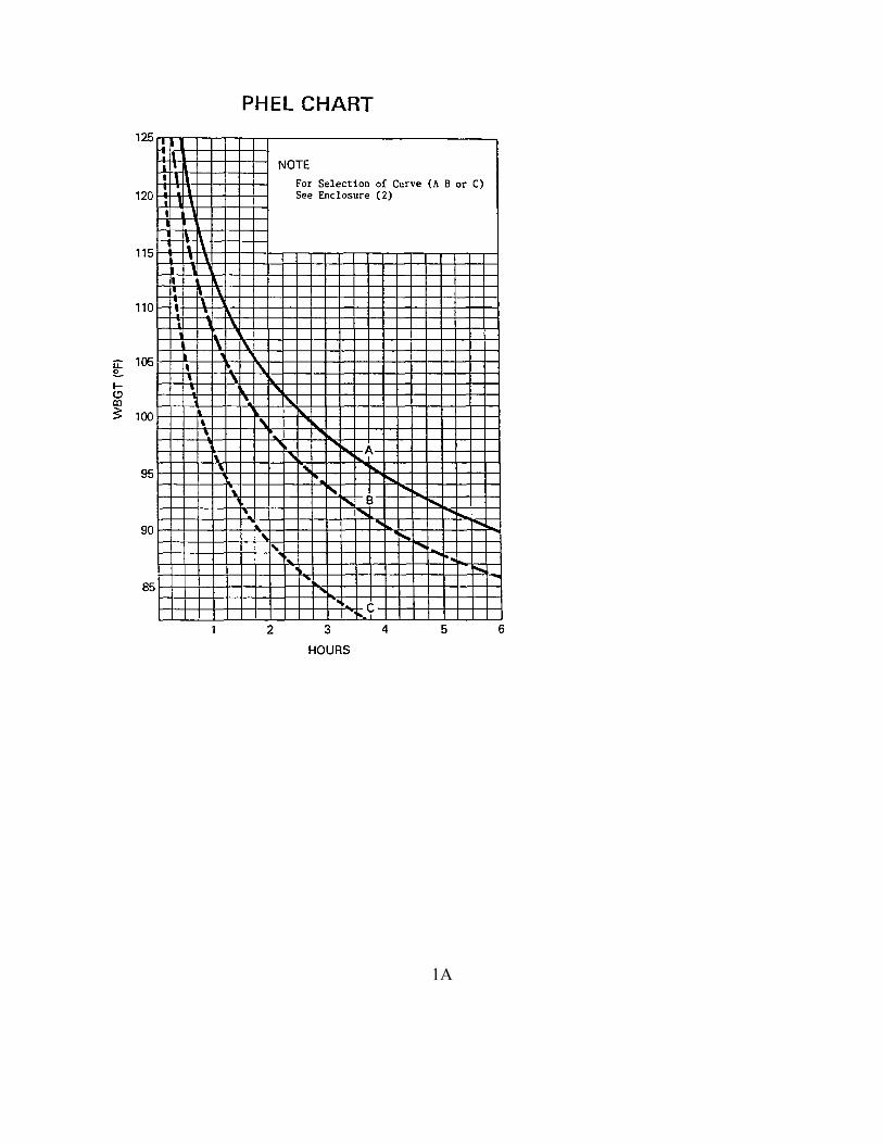
level of heat stress, an additional piece of information is required--the degree of effort entailed by the particular job. The more strenuous the job the shorter the allowable stay exposure time. For general purposes, three levels of effort are shown on the PHEL CHART (Table 1-1), curves "A", "B" and "C" corresponding to "light", "medium" and "heavy" tasks. Examples for each of the curves are provided in the PHEL Curve General Applicability Table (see enclosure (2)). An example of non-engineering work tasks occur in the galley or scullery. For sustained work in these spaces, PHEL curve "C" herein should be used.
3-1

7 Take the WBGT index readings and transfer them onto the PHEL CHART (Table 1-1). For example, if your WBGT is 102 degrees F. at an engineering watch station, then you would use curve "A" on the PHEL CHART. Using the PHEL CHART, follow the 102 degrees F. WBGT reading across until it meets curve "A", then draw a line straight down until it intersects the hour line. It should give a reading of two and one-quarter hours which is the maximum time you can stay at that watch station. The Engineer Officer shall be notified of the stay time determined and personnel shall be rotated out of the heat stress watch or work area accordingly. The stay time shall be redetermined every watch or work rotation until the dry bulb temperature falls below 100 degrees F.
8 Personnel who have been directed to leave a heat stress environment because they have
reached their permissible exposure duration shall remain in a cool and dry area conducive to rapid physiological recovery. Preferred recovery environments are those which are air-conditioned. The length of recovery time in a cooled space shall be equal to twice the exposure time or four hours, whichever is less, provided there is no evidence of cumulative fatigue. Personnel exposed to a heat stress environment may stand watches as part of their recovery time so long as the space is cool and dry or air-conditioned.
9 If, after completing the necessary recovery period, an individual remains tired or unable to
carry out normal work requirements or has an increased incidence of health disorders, he/she shall be referred to the Health Service PO for follow-up evaluations. Further guidelines on the prevention of heat casualties can be found in COMDTINST 6200.4A, 21 September 1982. A Mishap Report (MISREP) shall be submitted on heat stress related illnesses in accordance with COMDTINST M5100.29, Chapter 2.
10 CORRECTIVE ACTION. Each heat stress condition shall be evaluated to determine if
the condition is caused in part or whole by a maintenance or design deficiency. Enclosure (3) provides guidance in determining whether heat stress conditions are traceable to maintenance or inherent design deficiencies. Enclosure (3) also can serve as a check list of items to be properly maintained in order to forestall heat stress conditions. Where maintenance or design deficiencies exist, repair action shall be taken as quickly as possible. Action required which is beyond the unit's capability shall be identified to the district commander by the CSMP system and by a Hazardous Condition Notification (Form CG 5082).
3-2
CHAPTER 4 TRAINING
A. MONITORS. Personnel performing Heat Stress monitoring shall have a general
understanding of the information contained in this manual and the WBGT meter technical manual. They shall demonstrate proficiency in: 1 Assembling and using the WBGT meter, including the ability to manually calculate the
WBGT index and by comparison with the meter reading, determine whether an error has occurred;
2 Completing the required forms;
3 Interpreting the PHEL CHART;
4 Using the emergency environmental monitoring equipment method in Chapter 5.
B. FILMS. The use of educational film MN-1136, "Heat Stress Monster," will provide the
needed information on general PHEL curves and the significance of heat stress for all hands. Monitors should be shown the Navy educational film MN-13042, "Care and Use of the Heat Stress Meter," as part of their training. Another source of information is the Health Services Petty Officer who is required to receive training in heat stress before reporting aboard.
4-1

CHAPTER 5 EMERGENCY ENVIRONMENTAL MONITORING EQUIPMENT
A. MONITORING. There are no proven shortcut devices or equations to evaluate heat stress
conditions which will not increase the risk to personnel in environments comparable with those aboard Coast Guard cutters. The emergency environmental monitoring equipment method herein will almost always significantly underestimate the level of heat stress. In the event that an operable WBGT meter is not available, the only approved alternative monitoring method is to have a motorized psychrometer (NSN 1H-6685-00-935-1389) on board. The psychrometer does not have a globe thermometer and, therefore, cannot measure radiant heat or account for convective cooling. Furthermore, it cannot be used as a substitute for all of the components in the WBGT equation given in Chapter 2. The psychrometer measures only the dry- and wet-bulb temperatures, which must be done with the psychrometer shield in its proper position. If one can assume that there were reliable globe temperatures recorded from the last complete heat stress survey, under similar plant operating and material conditions, and that there were reliable globe temperatures recorded before the meter became inoperable, then one should average at least the last three such potentially reliable globe temperatures. Use the psychrometric dry- and wet-bulb temperatures and the averaged prior globe temperature in the WBGT equation given in chapter 2.
Keep in mind that the averaged globe temperature cannot be equal or less than the psychrometric dry-bulb temperatures to be of any value. WBGT Index values, obtained by this strictly emergency monitoring method, should be used with the PHEL Chart; the resultant stay times will be approximate only.
5-1
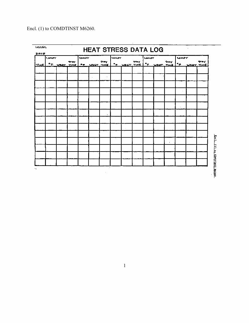
Encl. (1) to COMDTINST M6260.
1
1A

ENCL (2) to COMDTINST M6260.
PHEL CURVE GENERAL APPLICABILITY PHEL CURVES
STEAM PROPELLED SHIPS GAS TURBINE/DIESEL PROPELLED
A Fireroom boilder water level checkman and engine room watches during other than heavy reparir or casualty control activity.
Engineering operating watch stations during other than heavy repair or casualty control activity.
B Fire room and engine room watch supervisors during roving inspection of space. Fire room burnerman during other than casualty control functions Fire room and engine room messengers during other than full power conditions or when continuous mobility is not required. Laundry personnel
Lower and upper level watch standers during other than heavy repair or casualty control functions. Messenger during other than full power conditions or continuous mobility. Laundry personnel.
C. Any personnel involved in heavy repair work or casualty control functions Fireroom and engine room messengers during ufll power operation or other activities requiring continuous mobility.
Any personnel involved in heavy repair work or casualty control functions. Medssengers during full power operation or activities requiring continuous mobility.
Note: Use PHEL Curve “V” from Fig. 3-5 of NAVMED P-5010-3 for all scullery personnel.
Encl. (3) to COMDTINST M6260.
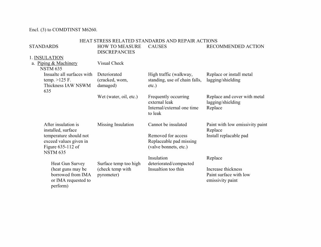
HEAT STRESS RELATED STANDARDS AND REPAIR ACTIONS STANDARDS HOW TO MEASURE
DISCREPANCIES CAUSES RECOMMENDED ACTION
1. INSULATION a. Piping & Machinery Visual Check
NSTM 635 Insualte all surfaces with temp. >125 F. Thickness IAW NSWM 635 After insulation is installed, surface temperature should not exceed values given in Figure 635-112 of NSTM 635
Heat Gun Survey (heat guns may be borrowed from IMA or IMA requested to perform)
Deteriorated (cracked, worn, damaged) Wet (water, oil, etc.) Missing Insulation Surface temp too high (check temp with pyrometer)
High traffic (walkway, standing, use of chain falls, etc.) Frequently occurring external leak Internal/external one time to leak Cannot be insulated Removed for access Replaceable pad missing (valve bonnets, etc.) Insulation deteriorated/compacted Insualtion too thin
Replace or install metal lagging/shielding Replace and cover with metal lagging/shielding Replace Paint with low emissivity paint Replace Install replacable pad Replace Increase thickness Paint surface with low emissivity paint

Encl. (3) to COMDTINST M6260. STANDARDS HOW TO MEASURE
DISCREPANCIES
CAUSES
RECOMMENDED ACTION
Paint all surfaces >125 F with low emisivity paint (e <0.4) prior to insulation NSN 1H 8010-01-033-3779 (1 gal) NSN 1H 801-01-033-3778 (5 gal)
Note #1: For ships designed to MIL-STD-769D or earlier revisions, the surface temperature after installing insulation was limited to 150 F. 2. STEAM/WATER LEAKS a.Turbine Shaft Seals
NTNS 9411 (231) NSTM 9500 (502)
Some slight leakage is required to lubricate the shaft seals. Some turbine shaft seals are vented to a gland leak off system
Visual Visual
Shaft alignment Worn bearings mproper or worn packing installation Seal leaks beyond capacity of leak off system High exhaust steam pressure Low vacuum in glan leak off system (less than ½ inch vacuum)
Align shaft Replace bearings Replace packing Repair seal Rework exhaust valve Secure unneeded auxiliary machinery Check loop seals Isolate idle equiment.
2

Encl. (3) to COMDTINST M6260. STANDARDS HOW TO MEASURE
DISCREPANCIES CAUSES RECOMMENDED ACTION
b. Mechanical Pump Seals
NSTM 9470 (503)
Visual
Shaft alignment Worn bearings Improper or worn packing installation
Align shafting Replace bearings Replace when leakage exceeds five drops per minute.
c. Casing Joints (see NSTM 221)
Visual
Dirt on mating surfaces Improper bolt tightening
Clean surfaces Retighten bolts
d. Piping
NSTM 9480 (505) Visual
Pipe leaking Pipe broken
Replace Replace
e. Valves
No external leakage Visual
Worn or bent valve stem Damaged or worn valve stem packing Improper installation of gasket Damaged or incorrect size seal ring
Refinish or replace stem Replace packing Reinstall gasket Replace seal ring (must be replaced each time valve disassembled)
f. Flanged Joints
No leakage Visual
Cuts in flange faces Improper installation
Reface flange Reinstall
3
Encl. (3) to COMDTINST M6260. STANDARDS HOW TO MEASURE
DISCREPANCIES CAUSES RECOMMENDED ACTION
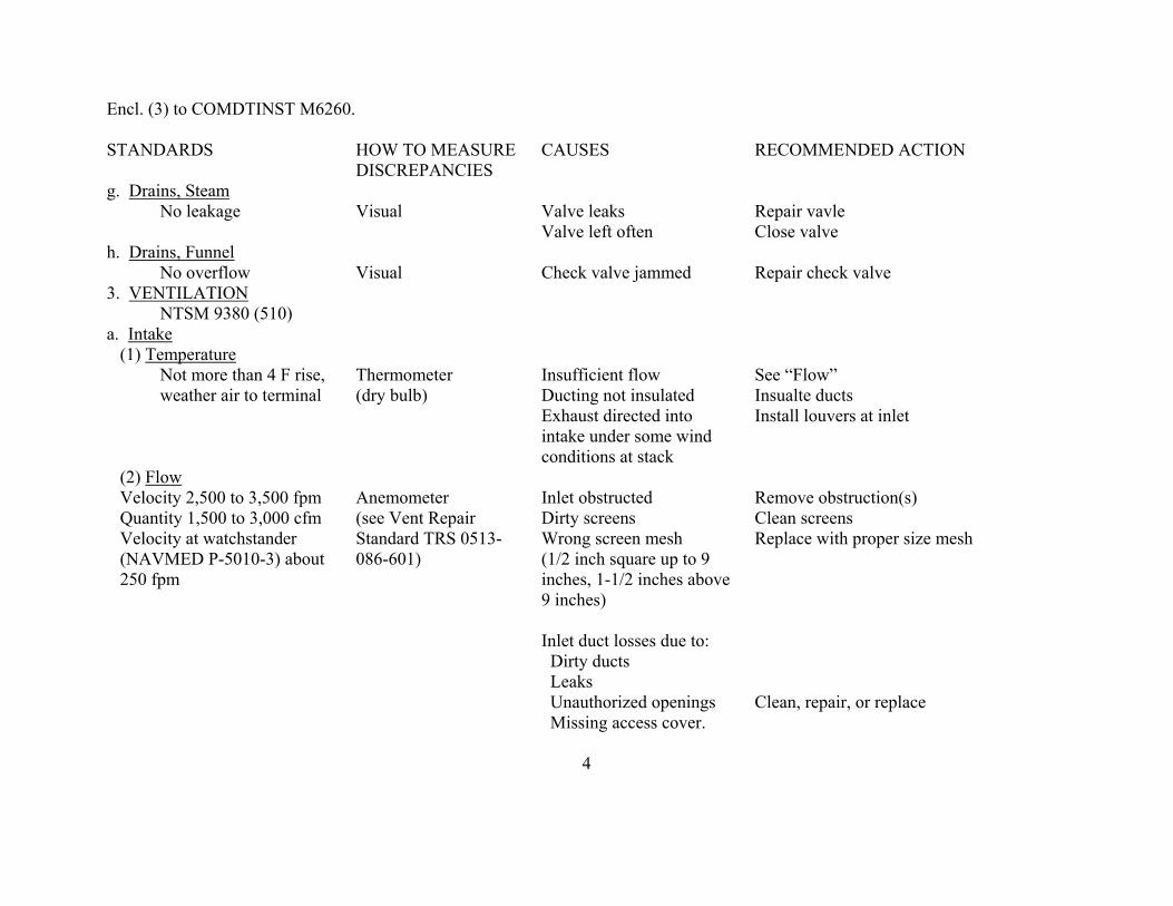
g. Drains, Steam No leakage
Visual
Valve leaks Valve left often
Repair vavle Close valve
h. Drains, Funnel No overflow
Visual
Check valve jammed
Repair check valve
3. VENTILATION NTSM 9380 (510)
a. Intake (1) Temperature
Not more than 4 F rise, weather air to terminal
Thermometer (dry bulb)
Insufficient flow Ducting not insulated Exhaust directed into intake under some wind conditions at stack
See “Flow” Insualte ducts Install louvers at inlet
(2) Flow Velocity 2,500 to 3,500 fpm Quantity 1,500 to 3,000 cfm Velocity at watchstander (NAVMED P-5010-3) about 250 fpm
Anemometer (see Vent Repair Standard TRS 0513-086-601)
Inlet obstructed Dirty screens Wrong screen mesh (1/2 inch square up to 9 inches, 1-1/2 inches above 9 inches) Inlet duct losses due to: Dirty ducts Leaks Unauthorized openings Missing access cover.
Remove obstruction(s) Clean screens Replace with proper size mesh Clean, repair, or replace
4
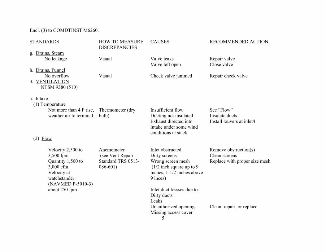
Encl. (3) to COMDTINST M6260. STANDARDS HOW TO MEASURE
DISCREPANCIES CAUSES RECOMMENDED ACTION
g. Drains, Steam No leakage
Visual
Valve leaks Valve left open
Repair valve Close valve
h. Drains, Funnel No overflow
Visual
Check valve jammed
Repair check valve
3. VENTILATION NTSM 9380 (510)
a. Intake (1) Temperature
Not more than 4 F rise, weather air to terminal
Thermometer (dry bulb)
Insufficient flow Ducting not insulated Exhaust directed into intake under some wind conditions at stack
See “Flow” Insulate ducts Install louvers at inlet4
(2) Flow
Velocity 2,500 to 3,500 fpm Quantity 1,500 to 3,000 cfm Velocity at watchstander (NAVMED P-5010-3) about 250 fpm
Anemometer (see Vent Repair Standard TRS 0513-086-601)
Inlet obstructed Dirty screens Wrong screen mesh (1/2 inch square up to 9 inches, 1-1/2 inches above 9 inces) Inlet duct lossses due to: Dirty ducts Leaks Unauthorized openings Missing access cover
Remove obstruction(s) Clean screens Replace with proper size mesh Clean, repair, or replace
5

Encl. (3) to COMDTINST M6260. STANDARDS HOW TO MEASURE
DISCREPANCIES CAUSES
RECOMMENDED ACTION
Supply terminal obstructed Terminal inoperable Terminal missing
Clean Replace terminal Replace terminal
Supply fan not working properly: Motor speek low Controller defective Improper speek interlock with exhaust fan
Repair Repair Repair
Supply air short circuited by exhaust terminal
Relocate supply or exhaust terminal
At least one supply E-terminal at each watchstander station, without damper, which can be pointed at watchstander
Visual Incorrect termianl type Replace terminal (should be corrosion resistant steel) Damper in duct at terminal not removed
Remove damper
b. Exhaust NAVSHIPS 0938-0180010 (HVAC) Design Criteria Manual) 125 percent of supply for 1200 pet ships 115 percent of supply for carriers and other ships Space pressure negative at ¼ to ½ inch of water is mandatory (air flow should be into space when acess is opened).
Anemometer U-Tuber Manometer
Exhaust fan not working properly: Motor speed low controller defective Exhaust erminal obstructed Dirty screens Wrong screens mesh (1/2 inch up to 9 inces, 1-1/2 inces above 9 inches)
Repair Repair Repair Clear exhaust erminal Replace Replace
6
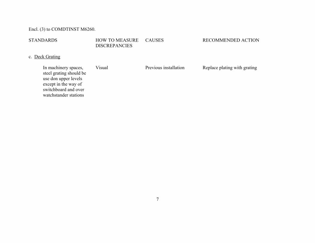
Encl. (3) to COMDTINST M6260. STANDARDS HOW TO MEASURE
DISCREPANCIES
CAUSES
RECOMMENDED ACTION
c. Deck Grating
In machinery spaces, steel grating should be use don upper levels except in the way of switchboard and over watchstander stations
Visual
Previous installation
Replace plating with grating
7