command line interface reference for the prosafe …...v v3.0, january 2008 contents command line...
TRANSCRIPT

Command Line Interface Reference for the ProSafe 7300S Series Layer-3 Stackable Switches, Software Version 7.1
202-10237-03 January 2008
NETGEAR, Inc.4500 Great America Parkway Santa Clara, CA 95054 USA

© 2008 by NETGEAR, Inc. All rights reserved. FullManual.
TrademarksNETGEAR and the NETGEAR logo are registered trademarks, and ProSafe is a trademark of NETGEAR, Inc. Microsoft, Windows, and Windows NT are registered trademarks of Microsoft Corporation.Other brand and product names are registered trademarks or trademarks of their respective holders. Portions of this document are copyright Intoto, Inc.January 2008
Statement of ConditionsIn the interest of improving internal design, operational function, and/or reliability, NETGEAR reserves the right to make changes to the products described in this document without notice.NETGEAR does not assume any liability that may occur due to the use or application of the product(s) or circuit layout(s) described herein.
EN 55 022 Declaration of ConformanceThis is to certify that the ProSafe 7300S Series Layer-3 Managed Stackable Switch is shielded against the generation of radio interference in accordance with the application of Council Directive 89/336/EEC, Article 4a. Conformity is declared by the application of EN 55 022 Class B (CISPR 22).
Certificate of the Manufacturer/ImporterIt is hereby certified that the ProSafe 7300S Series Layer-3 Managed Stackable Switch has been suppressed in accordance with the conditions set out in the BMPT-AmtsblVfg 243/1991 and Vfg 46/1992. The operation of some equipment (for example, test transmitters) in accordance with the regulations may, however, be subject to certain restrictions. Please refer to the notes in the operating instructions. The Federal Office for Telecommunications Approvals has been notified of the placing of this equipment on the market and has been granted the right to test the series for compliance with the regulations.
Bestätigung des Herstellers/ImporteursEs wird hiermit bestätigt, daß dasProSafe 7300S Series Layer-3 Managed Stackable Switch gemäß der im BMPT-AmtsblVfg 243/1991 und Vfg 46/1992 aufgeführten Bestimmungen entstört ist. Das vorschriftsmäßige Betreiben einiger Geräte (z.B. Testsender) kann jedoch gewissen Beschränkungen unterliegen. Lesen Sie dazu bitte die Anmerkungen in der Betriebsanleitung.Das Bundesamt für Zulassungen in der Telekommunikation wurde davon unterrichtet, daß dieses Gerät auf den Markt gebracht wurde und es ist berechtigt, die Serie auf die Erfüllung der Vorschriften hin zu überprüfen.
Voluntary Control Council for Interference (VCCI) StatementThis equipment is in the Class B category (information equipment to be used in a residential area or an adjacent area thereto) and conforms to the standards set by the Voluntary Control Council for Interference by Data Processing Equipment and Electronic Office Machines aimed at preventing radio interference in such residential areas. When used near a radio or TV receiver, it may become the cause of radio interference. Read instructions for correct handling.
ii
v3.0, January 2008

Product and Publication Details
Model Number: FSM73xxS/GSM73xxS
Publication Date: January 2008
Product Family: managed switch
Product Name: ProSafe 7300S Series Layer-3 Managed Stackable Switch
Home or Business Product: Business
Language: English
Publication Part Number: 202-10237-03
Publication Version Number 3.0
v3.0, January 2008
iii

v3.0, January 2008
iv

Contents
Command Line Interface Reference for the ProSafe 7300S Series Layer-3 Stackable Switches, Software Version 7.1Chapter 1 About This Manual
1.1 Audience................................................................................................................. 1-11.2 Scope...................................................................................................................... 1-11.3 Typographical Conventions .................................................................................... 1-21.4 Special Message Formats ...................................................................................... 1-21.5 How to Use This Manual......................................................................................... 1-31.6 How to Print this Manual......................................................................................... 1-31.7 Revision History...................................................................................................... 1-4
Chapter 2 Overview
2.1 Scope...................................................................................................................... 2-12.2 Product Concept ..................................................................................................... 2-12.3 Using the Command-Line Interface ........................................................................ 2-2
2.3.1 Command Syntax.......................................................................................... 2-22.3.2 Command Conventions................................................................................. 2-32.3.3 Unit-Slot-Port Naming Convention ................................................................ 2-52.3.4 Using the “No” Form of a Command ............................................................. 2-62.3.5 Command Modes.......................................................................................... 2-62.3.6 Entering CLI Commands ............................................................................... 2-92.3.7 Using CLI Help ............................................................................................ 2-102.3.8 Accessing the CLI ....................................................................................... 2-11
Chapter 3 Administrative Access Commands
3.1 Network Interface Commands ................................................................................ 3-13.1.1 enable............................................................................................................ 3-1
v
v3.0, January 2008

3.1.2 network parms (parameter) ........................................................................... 3-23.1.3 network mgmt_vlan ....................................................................................... 3-23.1.4 network protocol ............................................................................................ 3-23.1.5 show network ................................................................................................ 3-3
3.2 Configuring the Switch Management CPU (ezconfig) ............................................ 3-53.3 Console Port Access Commands ........................................................................... 3-7
3.3.1 configuration.................................................................................................. 3-73.3.2 lineconfig ....................................................................................................... 3-73.3.3 serial baudrate............................................................................................... 3-83.3.4 serial timeout ................................................................................................. 3-83.3.5 show serial .................................................................................................... 3-9
3.4 Telnet Commands................................................................................................. 3-103.4.1 telnet............................................................................................................ 3-103.4.2 transport input telnet.................................................................................... 3-103.4.3 transport output telnet ................................................................................. 3-113.4.4 session-limit................................................................................................. 3-113.4.5 session-timeout ........................................................................................... 3-123.4.6 telnetcon maxsessions ................................................................................ 3-123.4.7 telnetcon timeout ......................................................................................... 3-133.4.8 show telnet .................................................................................................. 3-133.4.9 show telnetcon ............................................................................................ 3-14
3.5 Secure Shell (SSH) Command ............................................................................. 3-153.5.1 ip ssh ........................................................................................................... 3-153.5.2 ip ssh protocol ............................................................................................. 3-153.5.3 sshcon maxsessions ................................................................................... 3-163.5.4 sshcon timeout ............................................................................................ 3-163.5.5 show ip ssh.................................................................................................. 3-17
3.6 Hypertext Transfer Protocol (HTTP) Commands.................................................. 3-173.6.1 ip http secure-port ....................................................................................... 3-173.6.2 ip http secure-protocol................................................................................. 3-183.6.3 ip http secure-server.................................................................................... 3-183.6.4 ip http server................................................................................................ 3-183.6.5 ip http java ................................................................................................... 3-193.6.6 ip http session hard-timeout ........................................................................ 3-193.6.7 ip http session maxsessions........................................................................ 3-19
vi
v3.0, January 2008

3.6.8 ip http session soft-timeout.......................................................................... 3-203.6.9 ip http secure-session hard-timeout ............................................................ 3-203.6.10 ip http secure-session maxsessions.......................................................... 3-213.6.11 ip http secure-session soft-timeout ............................................................ 3-213.6.12 network javamode ..................................................................................... 3-213.6.13 show ip http ............................................................................................... 3-22
3.7 User Account Commands..................................................................................... 3-243.7.1 users name.................................................................................................. 3-243.7.2 users passwd .............................................................................................. 3-253.7.3 users snmpv3 accessmode......................................................................... 3-253.7.4 users snmpv3 authentication....................................................................... 3-263.7.5 users snmpv3 encryption ............................................................................ 3-263.7.6 show loginsession ....................................................................................... 3-273.7.7 show users .................................................................................................. 3-273.7.8 disconnect ................................................................................................... 3-28
Chapter 4 Port and System Setup Commands
4.1 Port Configuration Commands ............................................................................... 4-14.1.1 interface......................................................................................................... 4-14.1.2 interface range .............................................................................................. 4-24.1.3 interface vlan ................................................................................................. 4-24.1.4 interface lag................................................................................................... 4-24.1.5 auto-negotiate ............................................................................................... 4-24.1.6 auto-negotiate all........................................................................................... 4-34.1.7 description ..................................................................................................... 4-34.1.8 mtu ................................................................................................................ 4-44.1.9 shutdown ....................................................................................................... 4-44.1.10 shutdown all ................................................................................................ 4-54.1.11 speed........................................................................................................... 4-54.1.12 speed all ...................................................................................................... 4-64.1.13 monitor session ........................................................................................... 4-64.1.14 no monitor ................................................................................................... 4-74.1.15 show monitor session.................................................................................. 4-74.1.16 show port..................................................................................................... 4-84.1.17 show port description .................................................................................. 4-8
vii
v3.0, January 2008

4.1.18 show port protocol ....................................................................................... 4-94.1.19 show port status .......................................................................................... 4-9
4.2 Pre-login Banner and System Prompt Commands............................................... 4-104.2.1 copy............................................................................................................. 4-104.2.2 set prompt ................................................................................................... 4-10
4.3 Simple Network Time Protocol (SNTP) Commands ............................................. 4-114.3.1 sntp broadcast client poll-interval ................................................................ 4-114.3.2 sntp client mode .......................................................................................... 4-114.3.3 sntp client port ............................................................................................. 4-124.3.4 sntp unicast client poll-interval .................................................................... 4-124.3.5 sntp unicast client poll-timeout .................................................................... 4-124.3.6 sntp unicast client poll-retry......................................................................... 4-134.3.7 sntp multicast client poll-interval.................................................................. 4-134.3.8 sntp server................................................................................................... 4-144.3.9 show sntp .................................................................................................... 4-144.3.10 show sntp client......................................................................................... 4-144.3.11 show sntp server ....................................................................................... 4-154.3.12 clock timezone........................................................................................... 4-16
4.4 MAC Address and MAC Database Commands.................................................... 4-174.4.1 network mac-address .................................................................................. 4-174.4.2 network mac-type........................................................................................ 4-174.4.3 macfilter....................................................................................................... 4-184.4.4 macfilter adddest ......................................................................................... 4-184.4.5 macfilter adddest all .................................................................................... 4-194.4.6 macfilter addsrc ........................................................................................... 4-194.4.7 macfilter addsrc all ...................................................................................... 4-204.4.8 bridge aging-time......................................................................................... 4-214.4.9 show forwardingdb agetime ........................................................................ 4-224.4.10 show mac-address-table multicast ............................................................ 4-224.4.11 show mac-address-table static .................................................................. 4-234.4.12 show mac-address-table stats................................................................... 4-23
4.5 DNS Client Commands......................................................................................... 4-244.5.1 ip domain-lookup......................................................................................... 4-254.5.2 ip domain-name........................................................................................... 4-254.5.3 ip name-server ............................................................................................ 4-25
viii
v3.0, January 2008

4.5.4 ip host.......................................................................................................... 4-264.5.5 clear host..................................................................................................... 4-264.5.6 show hosts .................................................................................................. 4-26
Chapter 5 Spanning Tree Protocol Commands
5.1 STP Configuration Commands ............................................................................... 5-15.1.1 spanning-tree ................................................................................................ 5-15.1.2 spanning-tree bpdumigrationcheck ............................................................... 5-25.1.3 spanning-tree configuration name................................................................. 5-25.1.4 spanning-tree configuration revision ............................................................. 5-35.1.5 spanning-tree edgeport ................................................................................. 5-35.1.6 spanning-tree edgeport all............................................................................. 5-35.1.7 spanning-tree forceversion............................................................................ 5-45.1.8 spanning-tree forward-time ........................................................................... 5-45.1.9 spanning-tree hello-time................................................................................ 5-55.1.10 spanning-tree max-age ............................................................................... 5-55.1.11 spanning-tree max-hops.............................................................................. 5-65.1.12 spanning-tree mst........................................................................................ 5-65.1.13 spanning-tree mst instance ......................................................................... 5-75.1.14 spanning-tree mst priority............................................................................ 5-85.1.15 spanning-tree mst vlan ................................................................................ 5-95.1.16 spanning-tree port mode ............................................................................. 5-95.1.17 spanning-tree port mode all......................................................................... 5-95.1.18 spanning-tree bpduforwarding................................................................... 5-10
5.2 STP Show Commands ......................................................................................... 5-105.2.1 show spanning-tree ..................................................................................... 5-105.2.2 show spanning-tree summary ..................................................................... 5-125.2.3 show spanning-tree interface ...................................................................... 5-135.2.4 show spanning-tree mst port detailed ......................................................... 5-145.2.5 show spanning-tree mst port summary ....................................................... 5-165.2.6 show spanning-tree mst summary .............................................................. 5-165.2.7 show spanning-tree vlan ............................................................................. 5-17
Chapter 6 VLAN Commands
6.1 VLAN Configuration Commands............................................................................. 6-1
ix
v3.0, January 2008

6.1.1 vlan association mac..................................................................................... 6-16.1.2 vlan database ................................................................................................ 6-26.1.3 network mgmt_vlan ....................................................................................... 6-26.1.4 vlan................................................................................................................ 6-36.1.5 vlan acceptframe ........................................................................................... 6-36.1.6 vlan ingressfilter ............................................................................................ 6-46.1.7 vlan makestatic.............................................................................................. 6-46.1.8 vlan name...................................................................................................... 6-56.1.9 vlan participation ........................................................................................... 6-56.1.10 vlan participation all ..................................................................................... 6-66.1.11 vlan port acceptframe all ............................................................................. 6-66.1.12 vlan port pvid all .......................................................................................... 6-76.1.13 vlan port tagging all ..................................................................................... 6-76.1.14 vlan port ingressfilter all............................................................................... 6-86.1.15 Global Config............................................................................................... 6-86.1.16 vlan protocol group...................................................................................... 6-86.1.17 vlan protocol group add protocol ................................................................. 6-86.1.18 vlan protocol group remove......................................................................... 6-96.1.19 protocol group ............................................................................................. 6-96.1.20 protocol vlan group.................................................................................... 6-106.1.21 protocol vlan group all ............................................................................... 6-106.1.22 vlan pvid .................................................................................................... 6-116.1.23 vlan tagging ............................................................................................... 6-11
6.2 VLAN Show Commands ....................................................................................... 6-126.2.1 show vlan .................................................................................................... 6-126.2.2 show vlan <vlan_id>.................................................................................... 6-126.2.3 show vlan association mac.......................................................................... 6-146.2.4 show vlan port ............................................................................................. 6-14
6.3 Double VLAN Commands..................................................................................... 6-156.3.1 dvlan-tunnel customer-id ............................................................................. 6-156.3.2 dvlan-tunnel etherType................................................................................ 6-166.3.3 mode dot1q-tunnel ...................................................................................... 6-166.3.4 mode dvlan-tunnel....................................................................................... 6-166.3.5 show dot1q-tunnel ....................................................................................... 6-186.3.6 show dot1q-tunnel interface ........................................................................ 6-18
x
v3.0, January 2008

6.3.7 show dvlan-tunnel ....................................................................................... 6-196.3.8 show dvlan-tunnel interface......................................................................... 6-19
6.4 Provisioning (IEEE 802.1p) Commands ............................................................... 6-206.4.1 vlan port priority all ...................................................................................... 6-206.4.2 vlan priority .................................................................................................. 6-20
Chapter 7 DHCP Commands
7.1 DHCP Server Commands (DHCP Config Pool Mode) ........................................... 7-27.1.1 ip dhcp pool ................................................................................................... 7-27.1.2 client-identifier ............................................................................................... 7-27.1.3 client-name.................................................................................................... 7-37.1.4 default-router ................................................................................................. 7-37.1.5 dns-server ..................................................................................................... 7-47.1.6 hardware-address ......................................................................................... 7-47.1.7 host................................................................................................................ 7-57.1.8 lease.............................................................................................................. 7-57.1.9 network.......................................................................................................... 7-67.1.10 bootfile......................................................................................................... 7-67.1.11 domain-name............................................................................................... 7-67.1.12 netbios-name-server ................................................................................... 7-77.1.13 netbios-node-type........................................................................................ 7-77.1.14 next-server .................................................................................................. 7-87.1.15 option........................................................................................................... 7-8
7.2 DHCP Server Commands (Global Config Mode) ................................................... 7-97.2.1 ip dhcp excluded-address ............................................................................. 7-97.2.2 ip dhcp ping packets.................................................................................... 7-107.2.3 service dhcp ................................................................................................ 7-107.2.4 ip dhcp bootp automatic .............................................................................. 7-117.2.5 ip dhcp conflict logging ................................................................................ 7-11
7.3 DHCP Server Clear and Show Commands .......................................................... 7-127.3.1 clear ip dhcp binding ................................................................................... 7-127.3.2 clear ip dhcp server statistics ...................................................................... 7-127.3.3 clear ip dhcp conflict.................................................................................... 7-127.3.4 show ip dhcp binding................................................................................... 7-127.3.5 show ip dhcp global configuration ............................................................... 7-13
xi
v3.0, January 2008

7.3.6 show ip dhcp pool configuration .................................................................. 7-137.3.7 show ip dhcp server statistics...................................................................... 7-147.3.8 show ip dhcp conflict ................................................................................... 7-15
7.4 DHCP and BOOTP Relay Commands ................................................................. 7-157.4.1 ip dhcp relay information option .................................................................. 7-167.4.2 bootpdhcprelay............................................................................................ 7-167.4.3 bootpdhcprelay maxhopcount ..................................................................... 7-177.4.4 bootpdhcprelay minwaittime........................................................................ 7-177.4.5 bootpdhcprelay serverip .............................................................................. 7-187.4.6 show bootpdhcprelay .................................................................................. 7-187.4.7 bootpdhcprelay backup-serverip ................................................................. 7-19
Chapter 8 GARP, GVRP, and GMRP Commands
8.1 GARP Commands .................................................................................................. 8-28.1.1 set garp timer join.......................................................................................... 8-28.1.2 set garp timer leave....................................................................................... 8-38.1.3 set garp timer leaveall ................................................................................... 8-48.1.4 show garp...................................................................................................... 8-4
8.2 GVRP Commands .................................................................................................. 8-58.2.1 set gvrp adminmode...................................................................................... 8-58.2.2 set gvrp interfacemode.................................................................................. 8-58.2.3 show gvrp configuration ................................................................................ 8-6
8.3 GMRP Commands.................................................................................................. 8-78.3.1 set gmrp adminmode..................................................................................... 8-78.3.2 set gmrp interfacemode................................................................................. 8-88.3.3 show gmrp configuration ............................................................................... 8-88.3.4 show mac-address-table gmrp .................................................................... 8-10
Chapter 9 Port-Based Traffic Control Commands
9.1 Port Security Commands........................................................................................ 9-19.1.1 port-security................................................................................................... 9-29.1.2 port-security max-dynamic ............................................................................ 9-29.1.3 port-security max-static ................................................................................. 9-39.1.4 port-security mac-address............................................................................. 9-39.1.5 port-security mac-address move ................................................................... 9-3
xii
v3.0, January 2008

9.1.6 show port-security ......................................................................................... 9-49.1.7 show port-security ......................................................................................... 9-49.1.8 show port-security dynamic........................................................................... 9-49.1.9 show port-security static................................................................................ 9-49.1.10 show port-security violation ......................................................................... 9-5
9.2 Storm Control Commands ...................................................................................... 9-59.2.1 storm-control broadcast................................................................................. 9-59.2.2 storm-control multicast all.............................................................................. 9-69.2.3 storm-control unicast all ................................................................................ 9-69.2.4 storm-control broadcast................................................................................. 9-79.2.5 storm-control multicast .................................................................................. 9-79.2.6 storm-control unicast ..................................................................................... 9-89.2.7 storm-control flowcontrol ............................................................................... 9-89.2.8 show storm-control ........................................................................................ 9-9
Chapter 10 SNMP Commands
10.1 SNMP Configuration Commands........................................................................ 10-110.1.1 snmp-server .............................................................................................. 10-110.1.2 snmp-server community ............................................................................ 10-210.1.3 snmp-server community ipaddr ................................................................. 10-210.1.4 snmp-server community ipmask................................................................ 10-310.1.5 snmp-server community mode.................................................................. 10-310.1.6 snmp-server community ro........................................................................ 10-410.1.7 snmp-server community rw ....................................................................... 10-410.1.8 snmp-server traps violation ....................................................................... 10-410.1.9 snmp-server traps ..................................................................................... 10-510.1.10 snmp-server traps bcaststorm................................................................. 10-510.1.11 snmp-server traps linkmode .................................................................... 10-610.1.12 snmp-server traps multiusers .................................................................. 10-610.1.13 snmp-server traps stpmode..................................................................... 10-610.1.14 snmptrap ................................................................................................. 10-710.1.15 snmptrap snmpversion ............................................................................ 10-810.1.16 snmptrap ipaddr ...................................................................................... 10-810.1.17 snmptrap mode ....................................................................................... 10-810.1.18 snmp trap link-status ............................................................................... 10-9
xiii
v3.0, January 2008

10.1.19 snmp trap link-status all........................................................................... 10-910.2 SNMP Show Commands .................................................................................. 10-10
10.2.1 show snmpcommunity............................................................................. 10-1010.2.2 show snmptrap ........................................................................................ 10-1110.2.3 show trapflags ......................................................................................... 10-11
Chapter 11 Port-Based Access and Authentication Commands
11.1 Port-Based Network Access Control Commands ............................................... 11-111.1.1 authentication login.................................................................................... 11-111.1.2 clear dot1x statistics .................................................................................. 11-311.1.3 clear radius statistics ................................................................................. 11-311.1.4 dot1x defaultlogin ...................................................................................... 11-311.1.5 dot1x initialize ............................................................................................ 11-311.1.6 dot1x login ................................................................................................. 11-311.1.7 dot1x max-req............................................................................................ 11-411.1.8 dot1x port-control....................................................................................... 11-411.1.9 dot1x port-control all .................................................................................. 11-511.1.10 dot1x re-authenticate............................................................................... 11-511.1.11 dot1x re-authentication ............................................................................ 11-611.1.12 dot1x system-auth-control ....................................................................... 11-611.1.13 dot1x timeout ........................................................................................... 11-611.1.14 dot1x port-method ................................................................................... 11-811.1.15 dot1x user................................................................................................ 11-811.1.16 users defaultlogin .................................................................................... 11-811.1.17 users login ............................................................................................... 11-911.1.18 show authentication................................................................................. 11-911.1.19 show authentication users ....................................................................... 11-911.1.20 show dot1x ............................................................................................ 11-1011.1.21 show dot1x users................................................................................... 11-1411.1.22 show users authentication ..................................................................... 11-14
11.2 RADIUS Commands ......................................................................................... 11-1411.2.1 radius accounting mode .......................................................................... 11-1411.2.2 radius server host .................................................................................... 11-1511.2.3 radius server key ..................................................................................... 11-1611.2.4 radius server msgauth ............................................................................. 11-16
xiv
v3.0, January 2008

11.2.5 radius server primary............................................................................... 11-1711.2.6 radius server retransmit........................................................................... 11-1711.2.7 radius server timeout ............................................................................... 11-1711.2.8 show radius ............................................................................................. 11-1811.2.9 show radius accounting ........................................................................... 11-1911.2.10 show radius statistics............................................................................. 11-20
Chapter 12 Port-Channel/LAG (802.3ad) Commands
12.1 Port-Channel Configuration Commands............................................................. 12-112.1.1 addport ...................................................................................................... 12-212.1.2 deleteport (Interface Config)...................................................................... 12-212.1.3 deleteport (Global Config) ......................................................................... 12-212.1.4 port-channel .............................................................................................. 12-312.1.5 clear port-channel...................................................................................... 12-312.1.6 port lacpmode............................................................................................ 12-312.1.7 port lacpmode all ....................................................................................... 12-412.1.8 port-channel adminmode........................................................................... 12-412.1.9 port-channel name .................................................................................... 12-412.1.10 port-channel linktrap................................................................................ 12-512.1.11 hashing-mode.......................................................................................... 12-5
12.2 Port-Channel Show Commands ......................................................................... 12-612.2.1 show port-channel ..................................................................................... 12-612.2.2 show port-channel ..................................................................................... 12-6
Chapter 13 Quality of Service (QoS) Commands
13.1 Class of Service (CoS) Commands .................................................................... 13-113.1.1 classofservice dot1p-mapping................................................................... 13-213.1.2 classofservice ip-precedence-mapping ..................................................... 13-213.1.3 classofservice ip-dscp-mapping ................................................................ 13-313.1.4 classofservice trust.................................................................................... 13-313.1.5 cos-queue min-bandwidth ......................................................................... 13-413.1.6 cos-queue strict ......................................................................................... 13-413.1.7 traffic-shape............................................................................................... 13-513.1.8 show classofservice dot1p-mapping ......................................................... 13-513.1.9 show classofservice ip-precedence-mapping............................................ 13-5
xv
v3.0, January 2008

13.1.10 show classofservice ip-dscp-mapping..................................................... 13-613.1.11 show classofservice trust......................................................................... 13-613.1.12 show interfaces cos-queue...................................................................... 13-7
13.2 Differentiated Services (DiffServ) Commands .................................................... 13-813.2.1 diffserv....................................................................................................... 13-9
13.3 DiffServ Class Commands.................................................................................. 13-913.3.1 class-map................................................................................................ 13-1013.3.2 class-map rename................................................................................... 13-1113.3.3 match ethertype....................................................................................... 13-1113.3.4 match any................................................................................................ 13-1113.3.5 match class-map ..................................................................................... 13-1113.3.6 match cos ................................................................................................ 13-1213.3.7 match destination-address mac .............................................................. 13-1313.3.8 match dstip .............................................................................................. 13-1313.3.9 match dstl4port........................................................................................ 13-1313.3.10 match ip dscp ........................................................................................ 13-1413.3.11 match ip precedence ............................................................................. 13-1413.3.12 match ip tos ........................................................................................... 13-1513.3.13 match protocol....................................................................................... 13-1613.3.14 match source-address mac................................................................... 13-1613.3.15 match srcip ............................................................................................ 13-1613.3.16 match srcl4port...................................................................................... 13-1713.3.17 match vlan ............................................................................................. 13-17
13.4 DiffServ Policy Commands ............................................................................... 13-1713.4.1 policy-map............................................................................................... 13-1813.4.2 assign-queue........................................................................................... 13-1913.4.3 drop ......................................................................................................... 13-1913.4.4 conform-color .......................................................................................... 13-2013.4.5 class ........................................................................................................ 13-2013.4.6 mark cos.................................................................................................. 13-2113.4.7 mark ip-dscp............................................................................................ 13-2113.4.8 mark ip-precedence................................................................................. 13-2213.4.9 police-simple ........................................................................................... 13-2213.4.10 policy-map rename................................................................................ 13-23
13.5 DiffServ Service Commands............................................................................. 13-24
xvi
v3.0, January 2008

13.5.1 service-policy........................................................................................... 13-2413.6 DiffServ Show Commands................................................................................ 13-25
13.6.1 show class-map....................................................................................... 13-2513.6.2 show diffserv ........................................................................................... 13-2613.6.3 show policy-map...................................................................................... 13-2713.6.4 show diffserv service ............................................................................... 13-2913.6.5 show diffserv service brief ....................................................................... 13-3013.6.6 show policy-map interface....................................................................... 13-3013.6.7 show service-policy ................................................................................. 13-31
13.7 MAC Access Control List (ACL) Commands .................................................... 13-3113.7.1 mac access-list extended........................................................................ 13-3213.7.2 mac access-list extended rename........................................................... 13-3313.7.3 {deny|permit} ........................................................................................... 13-3313.7.4 mac access-group................................................................................... 13-3513.7.5 show mac access-lists............................................................................. 13-35
13.8 IP Access Control List (ACL) Commands......................................................... 13-3613.8.1 access-list................................................................................................ 13-3713.8.2 ip access-group....................................................................................... 13-3813.8.3 show ip access-lists................................................................................. 13-3913.8.4 show access-lists .................................................................................... 13-39
Chapter 14 Routing Commands
14.1 Address Resolution Protocol (ARP) Commands ................................................ 14-114.1.1 arp ............................................................................................................. 14-214.1.2 ip proxy-arp ............................................................................................... 14-214.1.3 arp cachesize ............................................................................................ 14-314.1.4 arp dynamicrenew..................................................................................... 14-314.1.5 arp purge ................................................................................................... 14-314.1.6 arp resptime .............................................................................................. 14-414.1.7 arp retries .................................................................................................. 14-414.1.8 arp timeout ................................................................................................ 14-414.1.9 clear arp-cache.......................................................................................... 14-514.1.10 show arp.................................................................................................. 14-514.1.11 show arp brief .......................................................................................... 14-6
14.2 IP Routing Commands........................................................................................ 14-7
xvii
v3.0, January 2008

14.2.1 routing ....................................................................................................... 14-714.2.2 ip routing.................................................................................................... 14-814.2.3 ip address.................................................................................................. 14-814.2.4 ip route ...................................................................................................... 14-814.2.5 ip route default........................................................................................... 14-914.2.6 ip route distance ...................................................................................... 14-1014.2.7 ip forwarding............................................................................................ 14-1014.2.8 ip netdirbcast ........................................................................................... 14-1114.2.9 ip mtu....................................................................................................... 14-1114.2.10 encapsulation ........................................................................................ 14-1214.2.11 clear ip route all ..................................................................................... 14-1314.2.12 clear ip route ospf.................................................................................. 14-1314.2.13 clear ip route ospf <ip-address>............................................................ 14-1314.2.14 clear ip route rip..................................................................................... 14-1414.2.15 clear ip route rip <ip-address>............................................................... 14-1414.2.16 show ip .................................................................................................. 14-1414.2.17 show ip interface ................................................................................... 14-1514.2.18 show ip interface ................................................................................... 14-1614.2.19 show ip route ......................................................................................... 14-1614.2.20 show ip route bestroutes ....................................................................... 14-1714.2.21 show ip route entry ................................................................................ 14-1714.2.22 show ip route preferences ..................................................................... 14-1814.2.23 show ip stats.......................................................................................... 14-19
14.3 Router Discovery Protocol Commands............................................................. 14-1914.3.1 ip irdp....................................................................................................... 14-1914.3.2 ip irdp address......................................................................................... 14-2014.3.3 ip irdp holdtime ........................................................................................ 14-2114.3.4 ip irdp maxadvertinterval ......................................................................... 14-2114.3.5 ip irdp minadvertinterval .......................................................................... 14-2214.3.6 ip irdp preference .................................................................................... 14-2214.3.7 show ip irdp ............................................................................................. 14-22
14.4 Virtual LAN Routing Commands....................................................................... 14-2314.4.1 vlan routing.............................................................................................. 14-2314.4.2 show ip vlan............................................................................................. 14-24
14.5 Virtual Router Redundancy Protocol (VRRP) Commands................................ 14-24
xviii
v3.0, January 2008

14.5.1 ip vrrp ...................................................................................................... 14-2514.5.2 ip vrrp ...................................................................................................... 14-2514.5.3 ip vrrp mode ............................................................................................ 14-2614.5.4 ip vrrp ip................................................................................................... 14-2614.5.5 ip vrrp authentication ............................................................................... 14-2614.5.6 ip vrrp preempt ........................................................................................ 14-2714.5.7 ip vrrp priority........................................................................................... 14-2714.5.8 ip vrrp timers advertise ............................................................................ 14-2814.5.9 show ip vrrp interface stats...................................................................... 14-2814.5.10 show ip vrrp ........................................................................................... 14-3014.5.11 show ip vrrp interface ............................................................................ 14-3014.5.12 show ip vrrp interface <unit/slot/port> ................................................... 14-31
14.6 Open Shortest Path First (OSPF) Commands.................................................. 14-3114.6.1 router ospf ............................................................................................... 14-3214.6.2 enable (OSPF) ........................................................................................ 14-3214.6.3 ip ospf...................................................................................................... 14-3214.6.4 1583compatibility..................................................................................... 14-3314.6.5 area default-cost...................................................................................... 14-3314.6.6 area nssa................................................................................................. 14-3314.6.7 area nssa default-info-originate............................................................... 14-3414.6.8 area nssa no-redistribute (OSPF) ........................................................... 14-3414.6.9 area nssa no-summary (OSPF) .............................................................. 14-3414.6.10 area nssa translator-role (OSPF) .......................................................... 14-3414.6.11 area nssa translator-stab-intv ................................................................ 14-3514.6.12 area range............................................................................................. 14-3514.6.13 area stub ............................................................................................... 14-3514.6.14 area stub summarylsa ........................................................................... 14-3614.6.15 area virtual-link ...................................................................................... 14-3614.6.16 area virtual-link authentication............................................................... 14-3714.6.17 area virtual-link dead-interval ................................................................ 14-3714.6.18 area virtual-link hello-interval................................................................. 14-3814.6.19 area virtual-link retransmit-interval ........................................................ 14-3814.6.20 area virtual-link transmit-delay .............................................................. 14-3914.6.21 default-information originate (OSPF)..................................................... 14-3914.6.22 default-metric (OSPF) ........................................................................... 14-40
xix
v3.0, January 2008

14.6.23 distance ospf ......................................................................................... 14-4014.6.24 distribute-list out .................................................................................... 14-4114.6.25 exit-overflow-interval ............................................................................. 14-4114.6.26 external-lsdb-limit .................................................................................. 14-4214.6.27 ip ospf areaid......................................................................................... 14-4214.6.28 ip ospf authentication ............................................................................ 14-4214.6.29 ip ospf cost ............................................................................................ 14-4314.6.30 ip ospf dead-interval .............................................................................. 14-4314.6.31 ip ospf hello-interval .............................................................................. 14-4414.6.32 ip ospf priority ........................................................................................ 14-4414.6.33 ip ospf retransmit-interval ...................................................................... 14-4514.6.34 ip ospf transmit-delay ............................................................................ 14-4514.6.35 ip ospf mtu-ignore.................................................................................. 14-4614.6.36 router-id ................................................................................................. 14-4614.6.37 redistribute............................................................................................. 14-4614.6.38 maximum-paths..................................................................................... 14-4714.6.39 trapflags................................................................................................. 14-4714.6.40 show ip ospf .......................................................................................... 14-4814.6.41 show ip ospf area .................................................................................. 14-5014.6.42 show ip ospf database........................................................................... 14-5114.6.43 show ip ospf interface............................................................................ 14-5114.6.44 show ip ospf interface <unit/slot/port>................................................... 14-5214.6.45 show ip ospf interface stats ................................................................... 14-5414.6.46 show ip ospf neighbor ........................................................................... 14-5514.6.47 show ip ospf neighbor <ipaddr> ............................................................ 14-5614.6.48 show ip ospf range ................................................................................ 14-5714.6.49 show ip ospf stub table.......................................................................... 14-5814.6.50 show ip ospf virtual-link ......................................................................... 14-5814.6.51 show ip ospf virtual-link <area_id> ........................................................ 14-59
14.7 Routing Information Protocol (RIP) Commands ............................................... 14-6014.7.1 router rip .................................................................................................. 14-6014.7.2 enable (RIP) ............................................................................................ 14-6014.7.3 ip rip......................................................................................................... 14-6014.7.4 auto-summary ......................................................................................... 14-6114.7.5 default-information originate (RIP) .......................................................... 14-61
xx
v3.0, January 2008

14.7.6 default-metric (RIP) ................................................................................. 14-6114.7.7 distance rip .............................................................................................. 14-6214.7.8 distribute-list out ...................................................................................... 14-6214.7.9 ip rip authentication ................................................................................. 14-6314.7.10 ip rip receive version ............................................................................. 14-6314.7.11 ip rip send version ................................................................................. 14-6414.7.12 hostroutesaccept ................................................................................... 14-6414.7.13 split-horizon ........................................................................................... 14-6514.7.14 redistribute............................................................................................. 14-6514.7.15 show ip rip ............................................................................................. 14-6614.7.16 show ip rip interface .............................................................................. 14-6714.7.17 show ip rip interface <unit/slot/port>...................................................... 14-67
Chapter 15 IGMP Snooping Commands
15.1 IGMP Snooping Configuration Commands......................................................... 15-115.1.1 ip igmpsnooping ........................................................................................ 15-115.1.2 ip igmpsnooping interfacemode ................................................................ 15-215.1.3 ip igmpsnooping groupmembership-interval ............................................. 15-315.1.4 ip igmpsnooping maxresponse.................................................................. 15-415.1.5 ip igmpsnooping mcrtexpiretime................................................................ 15-415.1.6 ip igmp mrouter ......................................................................................... 15-515.1.7 ip igmp mrouter interface........................................................................... 15-515.1.8 ip igmpsnooping unknown-multicast ......................................................... 15-6
15.2 IGMP Snooping Show Commands ..................................................................... 15-615.2.1 show ip igmp ............................................................................................. 15-615.2.2 show ip igmp mrouter interface ................................................................. 15-815.2.3 show ip igmp mrouter vlan ........................................................................ 15-815.2.4 show mac-address-table igmpsnooping.................................................... 15-8
15.3 IGMP Querier Commands .................................................................................. 15-915.3.1 ip igmpsnooping querier .......................................................................... 15-1015.3.2 ip igmpsnooping querier ip-address ........................................................ 15-1015.3.3 ip igmpsnooping querier query-interval ................................................... 15-1115.3.4 show ip igmpsnooping querier................................................................. 15-11
xxi
v3.0, January 2008

Chapter 16 Power Over Ethernet Commands
16.1 Power Over Ethernet (POE) Commands............................................................ 16-216.1.1 poe ............................................................................................................ 16-316.1.2 poe priority................................................................................................. 16-316.1.3 poe limit ..................................................................................................... 16-316.1.4 poe usagethreshold................................................................................... 16-416.1.5 show poe port info ..................................................................................... 16-416.1.6 show poe................................................................................................... 16-5
Chapter 17 Stacking Commands
17.1 Dedicated Port Stacking ..................................................................................... 17-117.1.1 stack .......................................................................................................... 17-117.1.2 member ..................................................................................................... 17-217.1.3 switch priority............................................................................................. 17-217.1.4 switch renumber ........................................................................................ 17-317.1.5 movemanagement..................................................................................... 17-317.1.6 archive copy-sw......................................................................................... 17-317.1.7 archive download-sw................................................................................. 17-417.1.8 slot............................................................................................................. 17-417.1.9 set slot disable........................................................................................... 17-517.1.10 set slot power .......................................................................................... 17-517.1.11 reload....................................................................................................... 17-617.1.12 show slot ................................................................................................. 17-617.1.13 show supported cardtype ........................................................................ 17-717.1.14 show switch ............................................................................................. 17-817.1.15 show supported switchtype ..................................................................... 17-9
17.2 Front Panel Stacking Commands ..................................................................... 17-1017.2.1 stack-port................................................................................................. 17-1017.2.2 qos-mode ................................................................................................ 17-1117.2.3 show stack-port ....................................................................................... 17-1117.2.4 show stack-port counters ........................................................................ 17-1217.2.5 show stack-port diag ............................................................................... 17-12
xxii
v3.0, January 2008

Chapter 18 System Maintenance Commands
18.1 System Information and Statistics Commands ................................................... 18-118.1.1 show arp switch......................................................................................... 18-118.1.2 show eventlog ........................................................................................... 18-218.1.3 show hardware .......................................................................................... 18-218.1.4 show interface ........................................................................................... 18-318.1.5 show interface ethernet ............................................................................. 18-518.1.6 show logging ........................................................................................... 18-1418.1.7 show mac-addr-table............................................................................... 18-1518.1.8 clear mac-addr-table ............................................................................... 18-1618.1.9 show running-config ................................................................................ 18-1618.1.10 show running-config interface ............................................................... 18-1618.1.11 terminal length ....................................................................................... 18-1718.1.12 show sysinfo.......................................................................................... 18-17
18.2 System Utility Commands................................................................................. 18-1818.2.1 traceroute ................................................................................................ 18-1818.2.2 clear config .............................................................................................. 18-1818.2.3 clear counters.......................................................................................... 18-1818.2.4 clear igmpsnooping ................................................................................. 18-1818.2.5 clear pass ................................................................................................ 18-1918.2.6 enable passwd ........................................................................................ 18-1918.2.7 clear port-channel.................................................................................... 18-2018.2.8 clear traplog............................................................................................. 18-2018.2.9 clear vlan ................................................................................................. 18-2018.2.10 copy....................................................................................................... 18-2018.2.11 logout..................................................................................................... 18-2218.2.12 ping........................................................................................................ 18-2218.2.13 reload .................................................................................................... 18-22
18.3 Logging Commands.......................................................................................... 18-2318.3.1 logging buffered....................................................................................... 18-2318.3.2 logging buffered wrap.............................................................................. 18-2318.3.3 logging console ....................................................................................... 18-2418.3.4 logging host ............................................................................................. 18-2418.3.5 logging host remove................................................................................ 18-24
xxiii
v3.0, January 2008
18.3.6 logging port.............................................................................................. 18-2518.3.7 logging syslog.......................................................................................... 18-2518.3.8 show logging ........................................................................................... 18-2518.3.9 show logging buffered ............................................................................. 18-2718.3.10 clear logging buffered............................................................................ 18-2718.3.11 show logging hosts ................................................................................ 18-2718.3.12 show logging traplogs............................................................................ 18-28
18.4 CLI Command Logging Command ................................................................... 18-2818.4.1 logging cli-command ............................................................................... 18-28
18.5 Configuration Scripting Commands .................................................................. 18-2918.5.1 script apply .............................................................................................. 18-3018.5.2 script delete ............................................................................................. 18-3018.5.3 script list .................................................................................................. 18-3018.5.4 show script .............................................................................................. 18-3018.5.5 script validate .......................................................................................... 18-31
18.6 Packet Capture ................................................................................................. 18-3118.6.1 capture transmit packet ........................................................................... 18-3118.6.2 capture receive packet ............................................................................ 18-3118.6.3 capture all packets .................................................................................. 18-3218.6.4 capture wrap............................................................................................ 18-3218.6.5 show capture packets.............................................................................. 18-33
18.7 Dumping System Information ........................................................................... 18-3318.8 Setting the Output Length of show running-config............................................ 18-33
18.8.1 terminal length......................................................................................... 18-3318.8.2 terminal no length.................................................................................... 18-34
18.9 Save.................................................................................................................. 18-34Chapter 19 UDP Relay Commands
19.1 UDP Relay Configuration Commands ................................................................ 19-219.1.1 ip helper-address (global config mode) ..................................................... 19-219.1.2 ip helper-address (interface config mode)................................................. 19-3
19.2 UDP Relay Show Commands............................................................................. 19-319.2.1 show ip helper-address ............................................................................. 19-3
Appendix A Command Changes from Release 3 to Release 5
xxiv
v3.0, January 2008

Chapter 1About This Manual
This chapter introduces the Command Line Interface Reference for the ProSafe 7300S Series Layer-3 Stackable Switches, Software Version 7.1. It describes the command-line interface (CLI) commands used to view and configure the 7300S Series Stackable Switch software. You can access the CLI by using a direct connection to the serial port or by using telnet or SSH over a remote network connection.
1.1 AudienceThis document is for system administrators who configure and operate systems using 7300S Series Stackable Switch software. Software engineers who integrate 7300S Series Stackable Switch software into their hardware platform can also benefit from a description of the configuration options.
This document assumes that the reader has an understanding of the 7300S Series Stackable Switch software base and has read the appropriate specification for the relevant networking device platform. It also assumes that the reader has a basic knowledge of Ethernet and networking concepts.
1.2 ScopeThis manual is written for the 7300S Series Stackable Switch according to these specifications:
Table 1-1. Manual Specifications
Product ProSafe 7300S Series Layer-3 Managed Stackable Switch
Manual Part Number 202-10237-03
Manual Publication Date January 2008
About This Manual 1-1
v3.0, January 2008

Command Line Interface Reference for the ProSafe 7300S Series Layer-3 Stackable Switches,
1.3 Typographical ConventionsThis guide uses the following typographical conventions:
1.4 Special Message FormatsThis guide uses the following formats to highlight special messages:
Note: Product updates are available on the NETGEAR Web site at http://kbserver.netgear.com/products/.
Table 1-2. Typographical conventions
Italic Emphasis, books, CDs, file and server names, extensions
Bold User input, IP addresses, GUI screen text
Fixed Command prompt, CLI text, code.
Italic URL link
Note: This format is used to highlight of importance or special interest.
Tip: A time-saving or resource-saving procedural step.
Warning: This is a warning of possible damage to the equipment or software malfunction.
1-2 About This Manual
v3.0, January 2008

Command Line Interface Reference for the ProSafe 7300S Series Layer-3 Stackable Switches,
1.5 How to Use This ManualThe HTML version of this manual includes the following:
• Buttons and for browsing forwards or backwards through the manual one page at a time.
• A button that displays the table of contents and possibly an button. Double-click on a link in the table of contents or index to navigate directly to where the topic is described in the manual.
• A button to access the full NETGEAR, Inc. online knowledge base for the product model.
• Links to PDF versions of the full manual and individual chapters.
1.6 How to Print this ManualTo print this manual, choose one of the following options.
• Printing a Page in the HTML View.
Each page in the HTML version of the manual is dedicated to a major topic. Use the Print button on the browser toolbar to print the page contents.
• Printing a Chapter.
Use the PDF of This Chapter link at the top left of any page.
– Click the PDF of This Chapter link at the top right of any page in the chapter you want to print. The PDF version of the chapter you were viewing opens in a browser window.
Your computer must have the free Adobe Acrobat reader installed in order to view and print PDF files. The Acrobat reader is available on the Adobe Web site at http://www.adobe.com.
Danger: Ignoring this type of warning could result in personal injury or death.
About This Manual 1-3
v3.0, January 2008

Command Line Interface Reference for the ProSafe 7300S Series Layer-3 Stackable Switches,
– Click the print icon in the window toolbar.
• Printing the Full Manual.
Use the Complete PDF Manual link at the top left of any page.
– Click the Complete PDF Manual link at the top left of any page in the manual. The PDF version of the complete manual opens in a browser window.
– Click the print icon in the window toolbar.
1.7 Revision HistoryTable 1-3 lists the revision history of this manual.
Tip: If your printer supports printing of two or more pages on a single sheet of paper, you can save paper and printer ink by clicking the printer Properties button and increasing the number of pages per sheet.
Tip: If your printer supports printing of two or more pages on a single sheet of paper, you can save paper and printer ink by clicking the printer Properties button and increasing the number of pages per sheet.
Table 1-3. Revision History of This Manual
Document Part Number Version Publication Date Change Description
202-10237-01 1.0 February 2007 Document for version 6.0 software release
202-10237-02 1.0 February 2007 Document for version 6.1 software release
1-4 About This Manual
v3.0, January 2008

Chapter 2Overview
The 7300S Series Stackable Switch software has two purposes:
• Assist attached hardware in switching frames, based on Layer 2, 3, or 4 information contained in the frames.
• Provide a complete device management portfolio to the network administrator.
2.1 Scope7300S Series Stackable Switch software encompasses both hardware and software support. It software is partitioned to run in the following processors:
• CPU—This code runs the networking device management portfolio and controls the overall networking device hardware. It also assists in frame forwarding, as needed and specified. This code is designed to run on multiple platforms with minimal changes from platform to platform.
• Networking Device Processor—This code does the majority of the packet switching, usually at wire speed. This code is platform dependent, and substantial changes might exist across products.
2.2 Product ConceptFast Ethernet and Gigabit Ethernet switching continues to evolve from high-end backbone applications to desktop switching applications. The price of the technology continues to decline, while performance and feature sets continue to improve. Devices that are capable of switching Layers 2, 3, and 4 are increasingly in demand. 7300S Series Stackable Switch software provides a flexible solution to these ever-increasing needs.
The exact functionality provided by each networking device on which the 7300S Series Stackable Switch software base runs varies depending upon the platform and requirements of NETGEAR.
Overview 2-1
v3.0, January 2008

Command Line Interface Reference for the ProSafe 7300S Series Layer-3 Stackable Switches,
7300S Series Stackable Switch software includes a set of comprehensive management functions for managing both the switch and the network. You can manage the 7300S Series Stackable Switch software by using one of the following three methods: • Web-based• VT100 interface• Simple Network Management Protocol (SNMP)
Each of the management methods enables you to configure, manage, and control the software locally or remotely using in-band or out-of-band mechanisms. Management is standards-based, with configuration parameters and a private MIB providing control for functions not completely specified in the MIBs.
2.3 Using the Command-Line InterfaceThe command-line interface (CLI) is a text-based way to manage and monitor the system. You can access the CLI by using a direct serial connection or by using a remote logical connection with telnet or SSH.
This section describes the CLI syntax, conventions, and modes. It contains the following topics:
• Section 2.3.1 “Command Syntax” on page 2-2
• Section 2.3.2 “Command Conventions” on page 2-3
• Section 2.3.3 “Unit-Slot-Port Naming Convention” on page 2-5
• Section 2.3.4 “Using the “No” Form of a Command” on page 2-6
• Section 2.3.5 “Command Modes” on page 2-6
• Section 2.3.6 “Entering CLI Commands” on page 2-9
• Section 2.3.7 “Using CLI Help” on page 2-10
• Section 2.3.8 “Accessing the CLI” on page 2-11
2.3.1 Command SyntaxA command is one or more words that might be followed by one or more parameters. Parameters can be required or optional values.
2-2 Overview
v3.0, January 2008

Command Line Interface Reference for the ProSafe 7300S Series Layer-3 Stackable Switches,
Some commands, such as show network or clear vlan, do not require parameters. Other commands, such as network parms, require that you supply a value after the command. You must type the parameter values in a specific order, and optional parameters follow required parameters. The following example describes the network parms command syntax:
Format network parms <ipaddr> <netmask> [gateway]
• network parms is the command name.
• <ipaddr> and <netmask> are parameters and represent required values that you must enter after you type the command keywords.
• [gateway] is an optional parameter, so you are not required to enter a value in place of the parameter.
The CLI Command Reference lists each command by the command name and provides a brief description of the command. Each command reference also contains the following information:
• Format shows the command keywords and the required and optional parameters.
• Mode identifies the command mode you must be in to access the command.
• Default shows the default value, if any, of a configurable setting on the device.
The show commands also contain a description of the information that the command displays.
2.3.2 Command ConventionsIn this document, the command name is in bold font. Parameters are in italic font. You must replace the parameter name with an appropriate value, which might be a name or number. Parameters are order dependent.
The parameters for a command might include mandatory values, optional values, or keyword choices. Table 2-1 describes the conventions this document uses to distinguish between value types. Table 2-1. Parameter Conventions
Symbol Example Description
<> angle brackets <value> Indicates that you must enter a value in place of the brackets and text inside them.
[] square brackets [value] Indicates an optional parameter that you can enter in place of the brackets and text inside them.
Overview 2-3
v3.0, January 2008

Command Line Interface Reference for the ProSafe 7300S Series Layer-3 Stackable Switches,
2.3.2.1 Common Parameter ValuesParameter values might be names (strings) or numbers. To use spaces as part of a name parameter, enclose the name value in double quotes. For example, the expression “System Name with Spaces” forces the system to accept the spaces. Empty strings (“ ”) are not valid user-defined strings. Table 2-2 describes common parameter values and value formatting.
{} curly braces {choice1 | choice2} Indicates that you must select a parameter from the list of choices.
| Vertical bars choice1 | choice2 Separates the mutually exclusive choices.
[{}] Braces within square brackets
[{choice1} choice2}] Indicate a choice within an optional element.
Table 2-2. Parameter Descriptions
Parameter Description
ipaddr This parameter is a valid IP address. You can enter the IP address in the following formats:a (32 bits)a.b (8.24 bits)a.b.c (8.8.16 bits)a.b.c.d (8.8.8.8)In addition to these formats, the CLI accepts decimal, hexidecimal and octal formats through the following input formats (where n is any valid hexidecimal, octal or decimal number):0xn (CLI assumes hexidecimal format)0n (CLI assumes octal format with leading zeros)n (CLI assumes decimal format)
macaddr The MAC address format is six hexadecimal numbers separated by colons, for example 00:06:29:32:81:40.
areaid Enter area IDs in dotted-decimal notation (for example, 0.0.0.1). An area ID of 0.0.0.0 is reserved for the backbone. Area IDs have the same format as IP addresses but are distinct from IP addresses. You can use the IP network number of the sub-netted network for the area ID.
routerid Enter the value of <routerid> in dotted-decimal notation, such as 0.0.0.1. A router ID of 0.0.0.0 is invalid.
Interface or unit/slot/port Valid slot and port number separated by forward slashes. For example, 0/1 represents slot number 0 and port number 1.
Table 2-1. Parameter Conventions
Symbol Example Description
2-4 Overview
v3.0, January 2008

Command Line Interface Reference for the ProSafe 7300S Series Layer-3 Stackable Switches,
2.3.3 Unit-Slot-Port Naming Convention7300S Series Stackable Switch software references physical entities such as cards and ports by using a Unit-Slot-Port (USP) naming convention. The software also uses this convention to identify certain logical entities, such as port-channel interfaces.
The slot number has two uses. In the case of physical ports, it identifies the card containing the ports. In the case of logical and CPU ports it also identifies the type of interface or port.
The port identifies the specific physical port or logical interface being managed on a given slot.
Logical Interface Logical slot and port number. This is applicable in the case of a port-channel (LAG). You can use the logical unit/slot/port to configure the port-channel.
Character strings Use double quotation marks to identify character strings, for example, “System Name with Spaces”. An empty string (“”) is not valid.
Table 2-3. Type of Slots
Slot Type Description
Physical slot numbers Physical slot numbers begin with zero, and are allocated up to the maximum number of physical slots.
Logical slot numbers Logical slots immediately follow physical slots and identify port-channel (LAG) or router interfaces.
CPU slot numbers The CPU slots immediately follow the logical slots.
Table 2-4. Type of Ports
Port Type Description
Physical Ports The physical ports for each slot are numbered sequentially starting from zero. For example, port one will be “0/1” with slot number always as zero.
Logical Interfaces Port-channel or Link Aggregation Group (LAG) interfaces are logical interfaces that are only used for bridging functions. VLAN routing interfaces are only used for routing functions.
CPU ports CPU ports are handled by the driver as one or more physical entities located on physical slots.
Table 2-2. Parameter Descriptions
Parameter Description
Overview 2-5
v3.0, January 2008

Command Line Interface Reference for the ProSafe 7300S Series Layer-3 Stackable Switches,
2.3.4 Using the “No” Form of a CommandThe no keyword is a specific form of an existing command and does not represent a new or distinct command. Almost every configuration command has a no form. In general, use the no form to reverse the action of a command or reset a value back to the default. For example, the no shutdown configuration command reverses the shutdown of an interface. Use the command without the keyword no to re-enable a disabled feature or to enable a feature that is disabled by default.
Only the configuration commands are available in the no form.
2.3.5 Command ModesThe CLI groups commands into modes according to the command function. Each of the command modes supports specific 7300S Series Stackable Switch software commands. The commands in one mode are not available until you switch to that particular mode, with the exception of the User EXEC mode commands. You can execute the User EXEC mode commands in the Privileged EXEC mode.
The command prompt changes in each command mode to help you identify the current mode. Table 2-5 describes the command modes and the prompts visible in that mode. Table 2-5. CLI Command Modes
Command Mode Prompt Mode Description
User EXEC Switch> Contains a limited set of commands to view basic system information.
Privileged EXEC Switch# Allows you to issue any EXEC command, enter the VLAN mode, or enter the Global Configuration mode.
Global Config Switch (Config)# Groups general setup commands and permits you to make modifications to the running configuration.
VLAN Config Switch (Vlan)# Groups all the VLAN commands.
2-6 Overview
v3.0, January 2008

Command Line Interface Reference for the ProSafe 7300S Series Layer-3 Stackable Switches,
Interface Config Switch (Interface <unit/slot/port>)#
Allows you to enable or modify the operation of an interface and provides access to the router interface configuration commands.Use this mode to set up a physical port for a specific logical connection operation.
Line Config Switch (line)# Allows you to configure various telnet settings and the console interface.
Policy Map Config Switch (Config policy-map)# Allows you to access the QoS Policy-Map configuration mode to configure the QoS Policy-Map.
Policy Class Config Switch (Config policy-class-map)# Consists of class creation, deletion, and matching commands. The class match commands specify Layer 2, Layer 3, and general match criteria.
Class Map Config Switch (Config class-map)# Allows you to access the QoS Class-Map configuration mode to configure QoS class maps.
Router OSPF Config
Switch (Config router)# Allows you to access the router OSPF configuration commands.
Router RIP Config Switch (Config router)# Allows you to access the router RIP configuration commands.
MAC Access-list Config
Switch (Config mac-access-list)# Allows you to create a MAC Access-List and to enter the mode containing Mac Access-List configuration commands.
DHCP Pool Config Switch (Config dhcp-pool)# Allows you to access the DHCP Pool configuration.
Stack Global Config Mode
Switch (Config stack)# Allows you to access the Stack Global Config Mode.
Table 2-5. CLI Command Modes (continued)
Command Mode Prompt Mode Description
Overview 2-7
v3.0, January 2008

Command Line Interface Reference for the ProSafe 7300S Series Layer-3 Stackable Switches,
Table 2-6 explains how to enter or exit each command mode.Table 2-6. CLI Mode Access and Exit
Command Mode Access Method Exit or Access Previous Mode
User EXEC This is the first level of access. To exit, enter logout.
Privileged EXEC From the User EXEC mode, enterenable.
To exit to the User EXEC mode, enterexit or press Ctrl-Z.
Global Config From the Privileged EXEC mode, enter configure.
To exit to the Privileged EXEC mode, enter exit, or press Ctrl-Z.
VLAN Config From the Privileged EXEC mode, enter vlan database.
To exit to the Privileged EXEC mode, enter exit, or press Ctrl-Z.
Interface Config From the Global Config mode, enter interface <unit/slot/port>.
To exit to the Global Config mode, enter exit. To return to the PrivilegedEXEC mode, enter Ctrl-Z.
Line Config From the Global Config mode, enter lineconfig.
To exit to the Global Config mode, enter exit. To return to the PrivilegedEXEC mode, enter Ctrl-Z.
Policy-Map Config
From the Global Config mode, enter policy-map.
To exit to the Global Config mode, enter exit. To return to the PrivilegedEXEC mode, enter Ctrl-Z.
Policy-Class-Map Config
From the Policy Map mode enter class.
To exit to the Policy Map mode, enterexit. To return to the Privileged EXEC mode, enter Ctrl-Z.
Class-Map Config
From the Global Config mode, enter class-map.
To exit to the Global Config mode, enter exit. To return to the PrivilegedEXEC mode, enter Ctrl-Z.
Router OSPF Config
From the Global Config mode, enter router ospf.
To exit to the Global Config mode, enter exit. To return to the PrivilegedEXEC mode, enter Ctrl-Z.
Router RIP Config
From the Global Config mode, enter router rip.
To exit to the Global Config mode, enter exit. To return to the PrivilegedEXEC mode, enter Ctrl-Z.
MAC Access-list Config
From the Global Config mode enter mac access-list extended <name>.
To exit to the Global Config mode, enter exit. To return to the PrivilegedEXEC mode, enter Ctrl-Z.
DHCP Pool Config
From the Global Config mode, enter ip dhcp pool <name>.
To exit to the Global Config mode, enter exit. To return to the PrivilegedEXEC mode, enter Ctrl-Z.
Stack Global Config Mode
From the Global Config mode, enter the stack command.
To exit to the Global Config mode, enter the exit command. To return to the Privileged EXEC mode, enter Ctrl-Z.
2-8 Overview
v3.0, January 2008

Command Line Interface Reference for the ProSafe 7300S Series Layer-3 Stackable Switches,
2.3.6 Entering CLI CommandsThe 7300S Series Stackable Switch supports several features to help you enter commands.
2.3.6.1 Command Completion and AbbreviationCommand completion finishes spelling the command when you type enough letters of a command to uniquely identify the command keyword. Once you have entered enough letters, press the SPACEBAR or TAB key to complete the word.
Command abbreviation allows you to execute a command when you type enough letters of a command to uniquely identify the command. You must enter all of the required keywords and parameters before you enter the command.
2.3.6.2 CLI Error MessagesIf you enter a command and the system is unable to execute it, an error message appears. Table 2-7 describes the most common CLI error messages.
2.3.6.3 CLI Line-Editing ConventionsTable 2-8 describes the key combinations you can use to edit commands or increase the speed of command entry. You can access this list from the CLI by entering help from the User or Privileged EXEC modes.
Table 2-7. CLI Error Messages
Message Text Description
% Invalid input detected at '^' marker.
Indicates that you entered an incorrect or unavailable command. The carat (^) shows where the invalid text is detected. This message also appears if any of the parameters or values are not recognized.
Command not found / Incomplete command. Use ? to list commands.
Indicates that you did not enter the required keywords or values.
Ambiguous command Indicates that you did not enter enough letters to uniquely identify the command.
Table 2-8. CLI Editing Conventions
Key Sequence Description
DEL or Backspace Delete previous character
Ctrl-A Go to beginning of line
Ctrl-E Go to end of line
Ctrl-F Go forward one character
Overview 2-9
v3.0, January 2008

Command Line Interface Reference for the ProSafe 7300S Series Layer-3 Stackable Switches,
2.3.7 Using CLI HelpEnter a question mark (?) at the command prompt to display the commands available in the current mode. (switch) >?
enable Enter into user privilege mode.help Display help for various special keys.logout Exit this session. Any unsaved changes are lost.ping Send ICMP echo packets to a specified IP address.show Display switch options and settings.
Enter a question mark (?) after each word you enter to display available command keywords or parameters.(switch) #network ?
javamode Enable/Disable.parms Configure Network Parameters of the router.protocol Select DHCP, BootP, or None as the network config protocol.mgmt_vlan Configure the Management VLAN ID of the switch.
Ctrl-B Go backward one character
Ctrl-D Delete current character
Ctrl-U, X Delete to beginning of line
Ctrl-K Delete to end of line
Ctrl-W Delete previous word
Ctrl-T Transpose previous character
Ctrl-P Go to previous line in history buffer
Ctrl-R Rewrites or pastes the line
Ctrl-N Go to next line in history buffer
Ctrl-Y Prints last deleted character
Ctrl-Q Enables serial flow
Ctrl-S Disables serial flow
Ctrl-Z Return to root command prompt
Tab, <SPACE> Command-line completion
Exit Go to next lower command prompt
? List available commands, keywords, or parameters
Table 2-8. CLI Editing Conventions
Key Sequence Description
2-10 Overview
v3.0, January 2008

Command Line Interface Reference for the ProSafe 7300S Series Layer-3 Stackable Switches,
If the help output shows a parameter in angle brackets, you must replace the parameter with a value.(switch) #network parms ?
<ipaddr> Enter the IP Address.
If there are no additional command keywords or parameters, or if additional parameters are optional, the following message appears in the output:<cr> Press Enter to execute the command
You can also enter a question mark (?) after typing one or more characters of a word to list the available command or parameters that begin with the letters, as shown in the following example:(switch) #show m?
mac-addr-table mac-address-table monitor
2.3.8 Accessing the CLIYou can access the CLI by using a direct console connection or by using a telnet or SSH connection from a remote management host.
For the initial connection, you must use a direct connection to the console port. You cannot access the system remotely until the system has an IP address and subnet mask. You can set the network configuration information manually, or you can configure the system to accept these settings from a BOOTP or DHCP server on your network. For more information, see Section 3.1 “Network Interface Commands” on page 3-1.
Overview 2-11
v3.0, January 2008

Command Line Interface Reference for the ProSafe 7300S Series Layer-3 Stackable Switches,
2-12 Overview
v3.0, January 2008

Chapter 3Administrative Access Commands
This section describes the management access and basic port configuration commands available in the 7300S Series Stackable Switch CLI.
This section contains the following topics:
• Section 3.1 “Network Interface Commands” on page 3-1
• Section 3.3 “Console Port Access Commands” on page 3-7
• Section 3.4 “Telnet Commands” on page 3-10
• Section 3.5 “Secure Shell (SSH) Command” on page 3-15
• Section 3.6 “Hypertext Transfer Protocol (HTTP) Commands” on page 3-17
• Section 3.7 “User Account Commands” on page 3-24
The commands in this section are divided into two functional groups:
• Show commands display switch settings, statistics, and other information.
• Configuration commands configure features and options of the switch. For every configuration command, there is a show command that displays the configuration setting.
To manage the device by using SNMP, see “SNMP Commands” in Chapter 10.
3.1 Network Interface CommandsThis section describes the commands you use to configure a logical interface for management access.
3.1.1 enableThis command gives you access to the Privileged EXEC mode. From the Privileged EXEC mode, you can configure the network interface.
Format enable
Mode User EXEC
Administrative Access Commands 3-1
v3.0, January 2008

Command Line Interface Reference for the ProSafe 7300S Series Layer-3 Stackable Switches,
3.1.2 network parms (parameter)This command sets the IP Address, subnet mask and gateway of the device. The IP Address and the gateway must be on the same subnet.
Format network (parms | parameter) <ipaddr> <netmask> [<gateway>]
Mode Privileged EXEC
3.1.3 network mgmt_vlanThis command configures the Management VLAN ID.
Default 1Format network mgmt_vlan <1-4069>
Mode Privileged EXEC
3.1.3.1 no network mgmt_vlanThis command sets the Management VLAN ID to the default.
Format no network mgmt_vlan
Mode Privileged EXEC
3.1.4 network protocolThis command specifies the network configuration protocol to be used. If you modify this value, change is effective immediately. If you modify this value, the change is effective immediately. If you use the bootp parameter, the switch periodically sends requests to a BootP server until a response is received. If you use the dhcp parameter, the switch periodically sends requests to a DHCP server until a response is received. If you use the none parameter, you must configure the network information for the switch manually.
Default noneFormat network protocol {none | bootp | dhcp}
Mode Privileged EXEC
3-2 Administrative Access Commands
v3.0, January 2008

Command Line Interface Reference for the ProSafe 7300S Series Layer-3 Stackable Switches,
3.1.5 show networkThis command displays configuration settings associated with the switch's network interface. The network interface is the logical interface used for in-band connectivity with the switch via any of the switch's front panel ports. The configuration parameters associated with the switch's network interface do not affect the configuration of the front panel ports through which traffic is switched or routed.
Format show network
Modes Privileged EXECUser EXEC
IP Address The IP address of the interface. The factory default value is 0.0.0.0
Subnet Mask The IP subnet mask for this interface. The factory default value is 0.0.0.0
Default Gateway The default gateway for this IP interface. The factory default value is 0.0.0.0
Burned In MAC Address The burned in MAC address used for in-band connectivity. Locally Administered MAC Address If desired, a locally administered MAC address can be con-
figured for in-band connectivity. To take effect, 'MAC Address Type' must be set to 'Locally Administered'. Enter the address as twelve hexadecimal digits (6 bytes) with a colon between each byte. Bit 1 of byte 0 must be set to a 1 and bit 0 to a 0, i.e. byte 0 should have the following mask 'xxxx xx10'. The MAC address used by this bridge when it must be referred to in a unique fashion. It is recommended that this be the numerically smallest MAC address of all ports that belong to this bridge. However it is only required to be unique. When concatenated with dot1dStpPriority a unique BridgeIdentifier is formed which is used in the Spanning Tree Protocol.
MAC Address Type Specifies which MAC address should be used for in-band
connectivity. The choices are the burned in or the Locally Administered address. The factory default is to use the burned in MAC address.
Administrative Access Commands 3-3
v3.0, January 2008

Command Line Interface Reference for the ProSafe 7300S Series Layer-3 Stackable Switches,
Network Configuration Protocol Current Indicates which network protocol is being used. The options
are bootp | dhcp | none. Java Mode Specifies if the switch should allow access to the Java applet
in the header frame. Enabled means the applet can be viewed. The factory default is disabled.
Web Mode Specifies if the switch should allow access to the Web Inter-face.
3-4 Administrative Access Commands
v3.0, January 2008

Command Line Interface Reference for the ProSafe 7300S Series Layer-3 Stackable Switches,
3.2 Configuring the Switch Management CPU (ezconfig)Format ezconfig
Mode Privileged EXEC
To manage the switch via the web GUI or telnet, an IP address needs to be assigned to the switch management CPU. Whereas there are CLI commands that can be used to do this, ezconfig simplifies the task. The tool is applicable to all NETGEAR 7000-series managed switches, and allows you to configure the following parameters:
1. The administrator’s user password and administrator-enable password
2. Management CPU IP address and network mask
3. System name and location information
The tool is interactive and uses questions to guide you through the steps required to perform its task. At the end of the session, it will ask you if you want to save the changed information. To see exactly what has been changed by ezconfig at the end of the session, use the show running-config command.
To perform any switch configuration other than the items listed above, use other CLI commands or the Web GUI.
Administrative Access Commands 3-5
v3.0, January 2008

Command Line Interface Reference for the ProSafe 7300S Series Layer-3 Stackable Switches,
The following is an example of an ezconfig session.
NETGEAR EZ Configuration Utility--------------------------------Hello and Welcome!
This utility will walk you thru assigning the IP address for the switch management CPU. It will allow you to save the changes at the end. After the session, simply use the newly assigned IP address to access the Web GUI using any public domain Web browser.
Admin password not defined. Do you want to change the password? (Y/N/Q) yEnter new password:******** Confirm new password:******** Password Changed!
The 'enable' password required for switch configuration via the command line interface is currently not configured. Do you wish to change it (Y/N/Q)? y
Enter new password:******** Confirm new password:******** Password Changed!
Assigning an IP address to your switch management
Current IP Address Configuration -------------------------------- IP address: 0.0.0.0 Subnet mask: 0.0.0.0Gateway address: 0.0.0.0
Would you like to assign an IP address now (Y/N/Q)? y
IP Address: 10.10.10.1 Subnet mask: 255.255.255.0Gateway address: 10.10.10.10
Do you want to assign switch name and location information (Y/N/Q)? y
System Name: testunit1 System Location: testlab System Contact: Bud Lightyear
3-6 Administrative Access Commands
v3.0, January 2008

Command Line Interface Reference for the ProSafe 7300S Series Layer-3 Stackable Switches,
3.3 Console Port Access CommandsThis section describes the commands you use to configure the console port. You can use a serial cable to connect a management host directly to the console port of the switch.
3.3.1 configurationThis command gives you access to the Global Config mode. From the Global Config mode, you can configure a variety of system settings, including user accounts. From the Global Config mode, you can enter other command modes, including Line Config mode.
Format configuration
Mode Privileged EXEC
3.3.2 lineconfigThis command gives you access to the Line Config mode, which allows you to configure various telnet settings and the console port.
Format lineconfig
Mode Global Config
There are changes detected, do you wish to save the changes permanently (Y/N)? y
The configuration changes have been saved succesfully. Please enter 'show running-config' to see the final configuration.
Thanks for using EzConfig!
Administrative Access Commands 3-7
v3.0, January 2008

Command Line Interface Reference for the ProSafe 7300S Series Layer-3 Stackable Switches,
3.3.3 serial baudrateThis command specifies the communication rate of the terminal interface. The supported rates are 1200, 2400, 4800, 9600, 19200, 38400, 57600, 115200.
Default 9600Format serial baudrate {1200 | 2400 | 4800 | 9600 | 19200
| 38400 | 57600 | 115200}
Mode Line Config
3.3.3.1 no serial baudrateThis command sets the communication rate of the terminal interface.
Format no serial baudrate
Mode Line Config
3.3.4 serial timeoutThis command specifies the maximum connect time (in minutes) without console activity. A value of 0 indicates that a console can be connected indefinitely. The time range is 0 to 160.
Default 5Format serial timeout <0-160>
Mode Line Config
3.3.4.1 no serial timeoutThis command sets the maximum connect time (in minutes) without console activity.
Format no serial timeout
Mode Line Config
3-8 Administrative Access Commands
v3.0, January 2008

Command Line Interface Reference for the ProSafe 7300S Series Layer-3 Stackable Switches,
3.3.5 show serialThis command displays serial communication settings for the switch.
Format show serial
Modes Privileged EXECUser EXEC
Serial Port Login Timeout (minutes) Specifies the time, in minutes, of inactivity on a Serial port
connection, after which the Switch will close the connection. Any numeric value between 0 and 160 is allowed, the factory default is 5. A value of 0 disables the timeout.
Baud Rate (bps) The default baud rate at which the serial port will try to con-nect. The available values are 1200, 2400, 4800, 9600, 19200, 38400,57600, and 115200 baud. The factory default is 9600 baud.
Character Size (bits) The number of bits in a character. The number of bits is
always 8. Flow Control Whether Hardware Flow-Control is enabled or disabled.
Hardware Flow Control is always disabled.Stop Bits The number of Stop bits per character. The number of Stop
bits is always 1.Parity Type The Parity Method used on the Serial Port. The Parity
Method is always None.
Administrative Access Commands 3-9
v3.0, January 2008

Command Line Interface Reference for the ProSafe 7300S Series Layer-3 Stackable Switches,
3.4 Telnet CommandsThis section describes the commands you use to configure and view telnet settings. You can use telnet to manage the device from a remote management host.
3.4.1 telnetThis command establishes a new outbound telnet connection to a remote host. The host value must be a valid IP address. Valid values for port should be a valid decimal integer in the range of 0 to 65535, where the default value is 23. If [debug] is used, the current telnet options enabled is displayed. The optional line parameter sets the outbound telnet operational mode as ‘linemode’, where by default, the operational mode is ‘character mode’. The noecho option disables local echo.
Format telnet <host> <port> [debug] [line] [noecho]
Modes Privileged EXECUser EXEC
3.4.2 transport input telnetThis command regulates new telnet sessions. If sessions are enabled, new telnet sessions can be established until there are no more sessions available. If sessions are disabled, no new telnet sessions are established. An established session remains active until the session is ended or an abnormal network error ends the session.
Default enabledFormat transport input telnet
Mode Line Config
3.4.2.1 no transport input telnetThis command disables telnet sessions. If sessions are disabled, no new telnet sessions are established.
Format no transport input telnet
Mode Line Config
3-10 Administrative Access Commands
v3.0, January 2008

Command Line Interface Reference for the ProSafe 7300S Series Layer-3 Stackable Switches,
3.4.3 transport output telnetThis command regulates new outbound telnet connections. If enabled, new outbound telnet sessions can be established until it reaches the maximum number of simultaneous outbound telnet sessions allowed. If disabled, no new outbound telnet session can be established. An established session remains active until the session is ended or an abnormal network error ends it.
Default enabledFormat transport output telnet
Mode Line Config
3.4.3.1 no transport output telnetThis command disables new outbound telnet connections. If disabled, no new outbound telnet connection can be established.
Format no transport output telnet
Mode Line Config
3.4.4 session-limitThis command specifies the maximum number of simultaneous outbound telnet sessions. A value of 0 indicates that no outbound telnet session can be established.
Default 5Format session-limit <0-5>
Mode Line Config
3.4.4.1 no session-limitThis command sets the maximum number of simultaneous outbound telnet sessions to the default value.
Format no session-limit
Mode Line Config
Administrative Access Commands 3-11
v3.0, January 2008

Command Line Interface Reference for the ProSafe 7300S Series Layer-3 Stackable Switches,
3.4.5 session-timeoutThis command sets the telnet session timeout value.The timeout value unit of time is minutes. A value of 0 indicates that a session remains active indefinitely.
Default 0Format session-timeout <0-160>
Mode Line Config
3.4.5.1 no session-timeoutThis command sets the telnet session timeout value to the default. The timeout value unit of time is minutes.
Format no session-timeout
Mode Line Config
3.4.6 telnetcon maxsessionsThis command specifies the maximum number of telnet connection sessions that can be established. A value of 0 indicates that no telnet connection can be established. The range is 0 to 5.
Default 5 Format telnetcon maxsessions <0-5>
Mode Privileged EXEC
3.4.6.1 no telnetcon maxsessionsThis command sets the maximum number of telnet connection sessions that can be established to the default value.
Format no telnetcon maxsessions
Mode Privileged EXEC
3-12 Administrative Access Commands
v3.0, January 2008

Command Line Interface Reference for the ProSafe 7300S Series Layer-3 Stackable Switches,
3.4.7 telnetcon timeoutThis command sets the telnet connection session timeout value, in minutes. A session is active as long as the session has not been idle for the value you set, which ranges from 1-160 minutes.
Default 5 Format telnetcon timeout <1-160>
Mode Privileged EXEC
3.4.7.1 no telnetcon timeoutThis command sets the telnet connection session timeout value to the default.
Format no telnetcon timeout
Mode Privileged EXEC
3.4.8 show telnetThis command displays the current outbound telnet settings.
Format show telnet
Modes Privileged EXECUser EXEC
Outbound Telnet Login Timeout Indicates the number of minutes an outbound telnet session is
allowed to remain inactive before being logged off.
Note: Changing the timeout value for active sessions does not become effective until the session is reaccessed. Also, any keystroke activates the new timeout duration.
Note: Changing the timeout value for active sessions does not become effective until the session is reaccessed. Also, any keystroke activates the new timeout duration.
Administrative Access Commands 3-13
v3.0, January 2008

Command Line Interface Reference for the ProSafe 7300S Series Layer-3 Stackable Switches,
Maximum Number of Outbound Telnet Sessions Indicates the number of simultaneous outbound telnet con-
nections allowed.Allow New Outbound Telnet Sessions Indicates whether outbound telnet sessions are allowed.
3.4.9 show telnetconThis command displays telnet settings.
Format show telnetcon Modes Privileged EXEC
User EXECRemote Connection Login Timeout (minutes) This object indicates the number of minutes a remote connec-
tion session is allowed to remain inactive before being logged off. May be specified as a number from 1 to 160. The factory default is 5.
Maximum Number of Remote Connection Sessions This object indicates the number of simultaneous remote con-
nection sessions allowed. The factory default is 5. Allow New Telnet Sessions Indicates that new telnet sessions will not be allowed when
set to no. The factory default value is yes.
3-14 Administrative Access Commands
v3.0, January 2008

Command Line Interface Reference for the ProSafe 7300S Series Layer-3 Stackable Switches,
3.5 Secure Shell (SSH) CommandThis section describes the commands you use to configure SSH access to the switch. Use SSH to access the switch from a remote management host.
3.5.1 ip sshThis command is used to enable SSH.
Default disabledFormat ip ssh
Mode Privileged EXEC
3.5.1.1 no ip sshThis command is used to disable SSH.
Format no ip ssh
Mode Privileged EXEC
3.5.2 ip ssh protocolThis command is used to set or remove protocol levels (or versions) for SSH. Either SSH1 (1), SSH2 (2), or both SSH 1 and SSH 2 (1 and 2) can be set.
Default 1 and 2Format ip ssh protocol [1] [2]
Mode Privileged EXEC
Note: The system allows a maximum of 5 SSH sessions.
Administrative Access Commands 3-15
v3.0, January 2008

Command Line Interface Reference for the ProSafe 7300S Series Layer-3 Stackable Switches,
3.5.3 sshcon maxsessionsThis command specifies the maximum number of SSH connection sessions that can be established. A value of 0 indicates that no ssh connection can be established. The range is 0 to 5.
Default 5 Format sshcon maxsessions <0-5>
Mode Privileged EXEC
3.5.3.1 no sshcon maxsessionsThis command sets the maximum number of allowed SSH connection sessions to the default value.
Format no sshcon maxsessions
Mode Privileged EXEC
3.5.4 sshcon timeoutThis command sets the SSH connection session timeout value, in minutes. A session is active as long as the session has been idle for the value set. The time is a decimal value from 1 to 160.
Changing the timeout value for active sessions does not become effective until the session is re accessed. Also, any keystroke activates the new timeout duration.
Default 5 Format sshcon timeout <1-160>
Mode Privileged EXEC
3.5.4.1 no sshcon timeoutThis command sets the SSH connection session timeout value, in minutes, to the default.
Changing the timeout value for active sessions does not become effective until the session is re accessed. Also, any keystroke activates the new timeout duration.
Format no sshcon timeout
Mode Privileged EXEC
3-16 Administrative Access Commands
v3.0, January 2008

Command Line Interface Reference for the ProSafe 7300S Series Layer-3 Stackable Switches,
3.5.5 show ip sshThis command displays the ssh settings.
Format show ip ssh
Mode Privileged EXECAdministrative Mode This field indicates whether the administrative mode of SSH
is enabled or disabled.Protocol Level The protocol level may have the values of version 1, version
2 or both versions 1 and version 2.Connections This field specifies the current SSH connections.
3.6 Hypertext Transfer Protocol (HTTP) CommandsThis section describes the commands you use to configure HTTP access to the switch. Access to the switch by using a Web browser is enabled by default. Everything you can view and configure by using the CLI is also available by using the Web.
3.6.1 ip http secure-portThis command is used to set the SSL port where port can be 1-65535 and the default is port 443.
Default 443Format ip http secure-port <portid>
Mode Privileged EXEC
3.6.1.1 no ip http secure-portThis command is used to reset the SSL port to the default value.
Format no ip http secure-port
Mode Privileged EXEC
Administrative Access Commands 3-17
v3.0, January 2008

Command Line Interface Reference for the ProSafe 7300S Series Layer-3 Stackable Switches,
3.6.2 ip http secure-protocolThis command is used to set protocol levels (versions). The protocol level can be set to TLS1, SSL3 or to both TLS1 and SSL3.
Default SSL3 and TLS1Format ip http secure-protocol [SSL3] [TLS1]
Mode Privileged EXEC
3.6.3 ip http secure-serverThis command is used to enable the secure socket layer for secure HTTP.
Default disabledFormat ip http secure-server
Mode Privileged EXEC
3.6.3.1 no ip http secure-serverThis command is used to disable the secure socket layer for secure HTTP.
Format no ip http secure-server
Mode Privileged EXEC
3.6.4 ip http serverThis command enables access to the switch through the Web interface. When access is enabled, you can login to the switch from the Web interface. When access is disabled, you cannot login to the switch's Web server. Disabling the Web interface takes effect immediately and affects all interfaces.
Default enabledFormat ip http server
Mode Privileged EXEC
3.6.4.1 no ip http serverThis command disables access to the switch through the Web interface. When access is disabled, you cannot login to the switch's Web server.
Format no ip http server
Mode Privileged EXEC
3-18 Administrative Access Commands
v3.0, January 2008

Command Line Interface Reference for the ProSafe 7300S Series Layer-3 Stackable Switches,
3.6.5 ip http javaThis command enables the Web Java mode. The Java mode applies to both secure and unsecure Web connections.
Default enabledFormat ip http java
Mode Privileged EXEC
3.6.5.1 no ip http javaThis command disables the Web Java mode. The Java mode applies to both secure and unsecure Web connections.
Format no ip http java
Mode Privileged EXEC
3.6.6 ip http session hard-timeoutConfigures the hard timeout for un-secure HTTP sessions in hours. Configuring this value to zero will give an infinite hard-timeout. When this timeout expires, the user will be forced to re-authenticate. This timer begins on initiation of the web session and is unaffected by the activity level of the connection.
Default 24Format ip http session hard-timeout <0-168>
Mode Privileged EXEC
3.6.6.1 no ip http session hard-timeoutRestores the hard timeout for un-secure HTTP sessions to the default value
Format no ip http session hard-timeout
Mode Privileged EXEC
3.6.7 ip http session maxsessionsThis command limits the number of allowable un-secure HTTP sessions. Zero is the configurable minimum.
Default 16Format ip http session maxsessions <0-16>
Mode Privileged EXEC
Administrative Access Commands 3-19
v3.0, January 2008

Command Line Interface Reference for the ProSafe 7300S Series Layer-3 Stackable Switches,
3.6.7.1 no ip http session maxsessionsRestores the the number of allowable un-secure HTTP sessions to the default value.
Format no ip http session maxsessions
Mode Privileged EXEC
3.6.8 ip http session soft-timeoutConfigures the soft timeout for un-secure HTTP sessions in minutes. Configuring this value to zero will give an infinite soft-timeout. When this timeout expires the user will be forced to re-authenticate. This timer begins on initiation of the Web session and is re-started with each access to the switch.
Default 60Format ip http session soft-timeout <0-60>
Mode Privileged EXEC
3.6.8.1 no ip http session soft-timeoutResets the soft timeout for un-secure HTTP sessions to the default value.
Format no ip http session soft-timeout
Mode Privileged EXEC
3.6.9 ip http secure-session hard-timeoutConfigures the hard timeout for secure HTTP sessions in hours. When this timeout expires, the user is forced to re-authenticate. This timer begins on initiation of the Web session and is unaffected by the activity level of the connection. The secure-session hard timeout cannot be set to zero (infinite).
Default 24Format ip http secure-session hard-timeout <1-168>
Mode Privileged EXEC
3.6.9.1 no ip http secure-session hard-timeoutResets the hard timeout for secure HTTP sessions to the default value
Format no ip http secure-session hard-timeout
Mode Privileged EXEC
3-20 Administrative Access Commands
v3.0, January 2008

Command Line Interface Reference for the ProSafe 7300S Series Layer-3 Stackable Switches,
3.6.10 ip http secure-session maxsessionsThis command limits the number of secure HTTP sessions. Zero is the configurable minimum.
Default 16Format ip http secure-session maxsessions <0-16>
Mode Privileged EXEC
3.6.10.1 no ip http secure-session maxsessionsRestores the the number of allowable secure HTTP sessions to the default value.
Format no ip http secure-session maxsessions
Mode Privileged EXEC
3.6.11 ip http secure-session soft-timeoutConfigures the soft timeout for secure HTTP sessions in minutes. When this timeout expires the user will be forced to re-authenticate. This timer begins on initiation of the Web session and is re-started with each access to the switch. The secure-session soft timeout cannot be set to zero (infinite).
Default 60Format ip http secure-session soft-timeout <1-60>
Mode Privileged EXEC
3.6.11.1 no ip http secure-session soft-timeoutResets the soft timeout for secure HTTP sessions to the default value.
Format no ip http secure-session soft-timeout
Mode Privileged EXEC
3.6.12 network javamodeThis command specifies whether or not the switch should allow access to the Java applet in the header frame of the Web interface. When access is enabled, the Java applet can be viewed from the Web interface. When access is disabled, the user cannot view the Java applet.
Default enabledFormat network javamode
Administrative Access Commands 3-21
v3.0, January 2008

Command Line Interface Reference for the ProSafe 7300S Series Layer-3 Stackable Switches,
Mode Privileged EXEC
3.6.12.1 no network javamodeThis command disallows access to the Java applet in the header frame of the Web interface. When access is disabled, the user cannot view the Java applet.
Format no network javamode
Mode Privileged EXEC
3.6.13 show ip httpThis command displays the http settings for the switch.
Format show ip http
Mode Privileged EXECHTTP Mode (Unsecure) Indicates the unsecure administrative mode.Java Mode The java applet administrative mode, which applies to both
secure and unsecure web connections.Maximum Allowable HTTP Sessions The number of allowable unsecure HTTP sessions.HTTP Session Hard Timeout The hard timeout for unsecure HTTP sessions in hours.HTTP Session Soft Timeout The soft timeout for unsecure HTTP sessions in minutes.HTTP Mode (Secure) The secure HTTP server administrative mode.Secure Port The secure HTTP server port number.Secure Port Protocol Level(s) The protocol level may have the values SSL3, TSL1, or both
SSL3 and TSL1.Maximum Allowable HTTPS Sessions The number of allowable secure HTTP sessions.HTTPS Session Hard Timeout The hard timeout for secure HTTP sessions in hours.
3-22 Administrative Access Commands
v3.0, January 2008

Command Line Interface Reference for the ProSafe 7300S Series Layer-3 Stackable Switches,
HTTPS Session Soft Timeout The soft timeout for secure HTTP sessions in minutes.
Administrative Access Commands 3-23
v3.0, January 2008

Command Line Interface Reference for the ProSafe 7300S Series Layer-3 Stackable Switches,
3.7 User Account CommandsThis section describes the commands you use to add, manage, and delete system users. The 7300S Series Stackable Switch has two default users: admin and guest. The admin user can view and configure system settings, and the guest user can view settings.
3.7.1 users nameThis command adds a new user account, if space permits. The account <username> can be up to eight characters in length. You can use alphanumeric characters as well as the dash (‘-’) and underscore (‘_’). The <username> is not case-sensitive.
You can define up to six user names.Format users name <username>
Mode Global Config
3.7.1.1 no users nameThis command removes a user account.
Format no users name <username>
Mode Global Config
Note: You cannot delete the admin user, and there is only one user allowed with read/write privileges. You can configure up to five read-only users on the system.
Note: You cannot delete the “admin” user account.
3-24 Administrative Access Commands
v3.0, January 2008
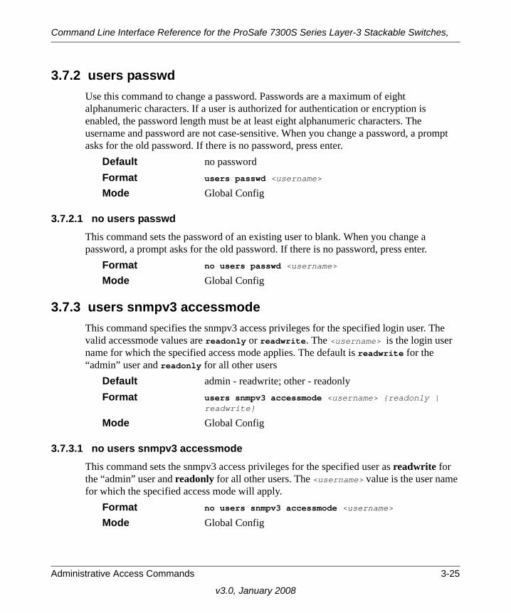
Command Line Interface Reference for the ProSafe 7300S Series Layer-3 Stackable Switches,
3.7.2 users passwdUse this command to change a password. Passwords are a maximum of eight alphanumeric characters. If a user is authorized for authentication or encryption is enabled, the password length must be at least eight alphanumeric characters. The username and password are not case-sensitive. When you change a password, a prompt asks for the old password. If there is no password, press enter.
Default no passwordFormat users passwd <username>
Mode Global Config
3.7.2.1 no users passwdThis command sets the password of an existing user to blank. When you change a password, a prompt asks for the old password. If there is no password, press enter.
Format no users passwd <username>
Mode Global Config
3.7.3 users snmpv3 accessmodeThis command specifies the snmpv3 access privileges for the specified login user. The valid accessmode values are readonly or readwrite. The <username> is the login user name for which the specified access mode applies. The default is readwrite for the “admin” user and readonly for all other users
Default admin - readwrite; other - readonlyFormat users snmpv3 accessmode <username> {readonly |
readwrite}
Mode Global Config
3.7.3.1 no users snmpv3 accessmodeThis command sets the snmpv3 access privileges for the specified user as readwrite for the “admin” user and readonly for all other users. The <username> value is the user name for which the specified access mode will apply.
Format no users snmpv3 accessmode <username>
Mode Global Config
Administrative Access Commands 3-25
v3.0, January 2008

Command Line Interface Reference for the ProSafe 7300S Series Layer-3 Stackable Switches,
3.7.4 users snmpv3 authenticationThis command specifies the authentication protocol to be used for the specified user. The valid authentication protocols are none, md5 or sha. If you specify md5 or sha, the login password is also used as the snmpv3 authentication password and therefore must be at least eight characters in length. The <username> is the user name associated with the authentication protocol.
Default no authenticationFormat users snmpv3 authentication <username> {none | md5
| sha}
Mode Global Config
3.7.4.1 no users snmpv3 authenticationThis command sets the authentication protocol to be used for the specified user to none. The <username> is the user name for which the specified authentication protocol is used.
Format users snmpv3 authentication <username>
Mode Global Config
3.7.5 users snmpv3 encryptionThis command specifies the encryption protocol used for the specified user. The valid encryption protocols are des or none.
If you select des, you can specify the required key on the command line. The encryption key must be 8 to 64 characters long. If you select the des protocol but do not provide a key, the user is prompted for the key. When you use the des protocol, the login password is also used as the snmpv3 encryption password, so it must be a minimum of eight characters. If you select none, you do not need to provide a key.
The <username> value is the login user name associated with the specified encryption. Default no encryptionFormat users snmpv3 encryption <username> {none |
des[key]}
Mode Global Config
3-26 Administrative Access Commands
v3.0, January 2008

Command Line Interface Reference for the ProSafe 7300S Series Layer-3 Stackable Switches,
3.7.5.1 no users snmpv3 encryptionThis command sets the encryption protocol to none. The <username> is the login user name for which the specified encryption protocol will be used.
Format no users snmpv3 encryption <username>
Mode Global Config
3.7.6 show loginsessionThis command displays current telnet and serial port connections to the switch.
Format show loginsession Mode Privileged EXECID Login Session IDUser Name The name the user will use to login using the serial port or
Telnet.Connection From IP address of the Telnet client machine or EIA-232 for the
serial port connection.Idle Time Time this session has been idle.Session Time Total time this session has been connected.Session Type Shows the type of session, which can be HTTP, HTTPS, tel-
net, serial, or SSH
3.7.7 show usersThis command displays the configured user names and their settings. This command is only available for users with Read/Write privileges. The SNMPv3 fields will only be displayed if SNMP is available on the system.
Format show users
Mode Privileged EXECUser Name The name the user enters to login using the serial port, Telnet
or Web.Access Mode Shows whether the user is able to change parameters on the
switch (Read/Write) or is only able to view them (Read Only). As a factory default, the “admin” user has Read/Write
Administrative Access Commands 3-27
v3.0, January 2008

Command Line Interface Reference for the ProSafe 7300S Series Layer-3 Stackable Switches,
access and the “guest” has Read Only access. There can only be one Read/Write user and up to five Read Only users.
SNMPv3 Access Mode This field displays the SNMPv3 Access Mode. If the value is
set to ReadWrite, the SNMPv3 user is able to set and retrieve parameters on the system. If the value is set to Rea-dOnly, the SNMPv3 user is only able to retrieve parameter information. The SNMPv3 access mode may be different than the CLI and Web access mode.
SNMPv3 Authentication This field displays the authentication protocol to be used for
the specified login user.SNMPv3 Encryption This field displays the encryption protocol to be used for the
specified login user.
3.7.8 disconnectThis command closes a telnet session.
Format disconnect {<sessionID> | all}
Mode Privileged EXEC
3-28 Administrative Access Commands
v3.0, January 2008

Chapter 4Port and System Setup Commands
This section describes general port and system setup commands available in the 7300S Series Stackable Switch CLI.
This section contains the following topics:
• Section 4.1 “Port Configuration Commands” on page 4-1
• Section 4.2 “Pre-login Banner and System Prompt Commands” on page 4-10
• Section 4.3 “Simple Network Time Protocol (SNTP) Commands” on page 4-11
• Section 4.4 “MAC Address and MAC Database Commands” on page 4-17
• Section 4.5 “DNS Client Commands” on page 4-24
The commands in this section are in one of three functional groups:
• Show commands display switch settings, statistics, and other information.
• Configuration commands configure features and options of the switch. For every configuration command, there is a show command that displays the configuration setting.
• Copy commands transfer or save configuration and informational files to and from the switch.
4.1 Port Configuration CommandsThis section describes the commands you use to view and configure port settings.
4.1.1 interfaceThis command gives you access to the Interface Config mode, which allows you to enable or modify the operation of an interface.
Format interface <unit/slot/port>
Mode Global Config
Port and System Setup Commands 4-1
v3.0, January 2008

Command Line Interface Reference for the ProSafe 7300S Series Layer-3 Stackable Switches,
4.1.2 interface rangeThis command gives you access to a range of port interfaces, allowing the same port configuration to be applied to a set of ports.
Format interface range <unit/slot/port>-<unit/slot/port>
Mode Global Config
4.1.3 interface vlanThis command gives you access to to the vlan virtual interface mode, which allows certain port configurations (for example, the IP address) to be applied to the VLAN interface. Type a question mark (?) after entering the interface configuration mode to see the available options.
Format interface vlan <vlan id>
Mode Global Config
4.1.4 interface lagThis command gives you access to the LAG (link aggregation, or port channel) virtual interface, which allows certain port configurations to be applied to the LAG interface. Type a question mark (?) after entering the interface configuration mode to see the available options.
Format interface lag <lag id>
Mode Global Config
4.1.5 auto-negotiateThis command enables automatic negotiation on a port.
Default enabledFormat auto-negotiate
Mode Interface Config
Note: The IP address cannot be assigned to a LAG virtual interface. The interface must be put under a VLAN group and an IP address assigned to the VLAN group.
4-2 Port and System Setup Commands
v3.0, January 2008

Command Line Interface Reference for the ProSafe 7300S Series Layer-3 Stackable Switches,
4.1.5.1 no auto-negotiateThis command disables automatic negotiation on a port.
Format no auto-negotiate
Mode Interface Config
4.1.6 auto-negotiate allThis command enables automatic negotiation on all ports. The default value is enable.
Format auto-negotiate all
Mode Global Config
4.1.6.1 no auto-negotiate allThis command disables automatic negotiation on all ports.
Format no auto-negotiate all
Mode Global Config
4.1.7 descriptionUse this command to create an alpha-numeric description of the port. The length can be up to 64 characters.
Format description <description>Mode Interface Config
Note: Automatic sensing is disabled when automatic negotiation is disabled.
Port and System Setup Commands 4-3
v3.0, January 2008

Command Line Interface Reference for the ProSafe 7300S Series Layer-3 Stackable Switches,
4.1.8 mtu This command sets the maximum transmission unit (MTU) size, in bytes, for physical and port-channel (LAG) interfaces. For the standard implementation, the MTU size is a valid integer between 1522 - 9216 for tagged packets and a valid integer between 1518 - 9216 for untagged packets.
Default 1518 (untagged)Format mtu <1518-9216>
Mode Interface Config
4.1.8.1 no mtu This command sets the default MTU size (in bytes) for the interface.
Format no mtu
Mode Interface Config
4.1.9 shutdownThis command disables a port.
Default enabledFormat shutdown
Mode Interface Config
Note: To receive and process packets, the Ethernet MTU must include any extra bytes that Layer-2 headers might require. To configure the IP MTU size, which is the maximum size of the IP packet (IP Header + IP payload), see Section 14.2.9 “ip mtu” on page 14-11.
Note: You can use the shutdown command on physical and port-channel (LAG) interfaces, but not on VLAN routing interfaces.
4-4 Port and System Setup Commands
v3.0, January 2008

Command Line Interface Reference for the ProSafe 7300S Series Layer-3 Stackable Switches,
4.1.9.1 no shutdownThis command enables a port.
Format no shutdown
Mode Interface Config
4.1.10 shutdown allThis command disables all ports.
Default enabledFormat shutdown all
Mode Global Config
4.1.10.1 no shutdown allThis command enables all ports.
Format no shutdown all
Mode Global Config
4.1.11 speed This command sets the speed and duplex setting for the interface.
Format speed {<100 | 10> <half-duplex | full-duplex>}
Mode Interface Config
Note: You can use the no shutdown command on physical and port-channel (LAG) interfaces, but not on VLAN routing interfaces.
Note: You can use the shutdown command on physical and port-channel (LAG) interfaces, but not on VLAN routing interfaces.
Note: You can use the shutdown command on physical and port-channel (LAG) interfaces, but not on VLAN routing interfaces.
Port and System Setup Commands 4-5
v3.0, January 2008

Command Line Interface Reference for the ProSafe 7300S Series Layer-3 Stackable Switches,
Acceptable values are:100h 100BASE-T half duplex 100f 100BASE-T full duplex 10h 10BASE-T half duplex 10f 10BASE-T full duplex
4.1.12 speed allThis command sets the speed and duplex setting for all interfaces.
Format speed all {<100 | 10> <half-duplex | full-duplex>}
Mode Global Config
Acceptable values are:100h 100BASE-T half-duplex 100f 100BASE-T full duplex 10h 10BASE-T half duplex 10f 10BASE-T full duplex
4.1.13 monitor sessionThis command configures a probe port and a monitored port for monitor session (port monitoring). To enable port monitoring, you must add a source interface, destination interface, and enable the mode. If enabled, the probe port monitors all the traffic received and transmitted on the physical monitored port.
Format monitor session <session-id> {source interface <unit/slot/port> | destination interface <unit/slot/port> | mode}
Mode Global Config
4-6 Port and System Setup Commands
v3.0, January 2008

Command Line Interface Reference for the ProSafe 7300S Series Layer-3 Stackable Switches,
4.1.13.1 no monitor sessionThis command removes the monitor session (port monitoring) designation from the source probe port, the destination monitored port and all VLANs. Once the port is removed from the VLAN, the user must manually add the port to any desired VLANs.
Format no monitor session <session-id>
Mode Global Config
4.1.14 no monitor This command removes all the source ports and a destination port and restores the default value for mirroring session mode for all the configured sessions.
Default enabledFormat no monitor
Mode Global config
4.1.15 show monitor sessionThis command displays the port monitoring information for the system. The <sessionid> parameter is an integer.
Format show monitor session <sessionid>
Mode Privileged EXECSession ID The session identifying number.Admin Mode Indicates whether the Port Monitoring feature is enabled or
disabled. The possible values are enable and disable.Probe Port The interface configured as the probe port.Mirrored Port The interface configured as the mirrored port.
Note: This command sets the monitor session (port monitoring) mode to disable and removes the source and destination interfaces.
Note: This is a stand-alone “no” command. This command does not have a “normal” form.
Port and System Setup Commands 4-7
v3.0, January 2008

Command Line Interface Reference for the ProSafe 7300S Series Layer-3 Stackable Switches,
4.1.16 show portThis command displays port information.
Format show port {<unit/slot/port> | all}
Mode Privileged EXECInterface Valid slot and port number separated by forward slashes.Type If not blank, this field indicates that this port is a special type
of port. The possible values are: Mon - this port is a monitoring port. Look at the Port Moni-toring screens to find out more information. Lag - this port is a member of a port-channel (LAG).
Probe - this port is a probe port.Admin Mode Selects the Port control administration state. The port must be
enabled in order for it to be allowed into the network. - May be enabled or disabled. The factory default is enabled.
Physical Mode Selects the desired port speed and duplex mode. If auto-nego-tiation support is selected, then the duplex mode and speed is set from the auto-negotiation process. Note that the maxi-mum capability of the port (full duplex -100M) is advertised. Otherwise, this object determines the port's duplex mode and transmission rate. The factory default is Auto.
Physical Status Indicates the port speed and duplex mode. Link Status Indicates whether the Link is up or down. Link Trap This object determines whether or not to send a trap when
link status changes. The factory default is enabled. LACP Mode Displays whether LACP is enabled or disabled on this port.
4.1.17 show port descriptionThis command displays the port description for every port
Format show port description <unit/slot/port>Mode Privileged EXECInterface Valid slot and port number separated by forward slashes.Description Shows the port description configured via the “description”
command
4-8 Port and System Setup Commands
v3.0, January 2008

Command Line Interface Reference for the ProSafe 7300S Series Layer-3 Stackable Switches,
4.1.18 show port protocol This command displays the Protocol-Based VLAN information for either the entire system, or for the indicated group.
Format show port protocol {<groupid> | all}
Mode Privileged EXECGroup Name This field displays the group name of an entry in the Proto-
col-based VLAN table.Group ID This field displays the group identifier of the protocol group.Protocol(s) This field indicates the type of protocol(s) for this group. VLAN This field indicates the VLAN associated with this Protocol
Group.Interface(s) This field lists the unit/slot/port interface(s) that are associ-
ated with this Protocol Group.
4.1.19 show port statusThis command displays the output with current port attributes and operational status.
Format show port status {<unit/slot/port> | all}
Mode Privileged ExecInterface Valid slot and port number separated by forward slashes.Media Type “Copper” or “Fiber” for combo port.Physical Mode Either “Auto” or fixed speed and duplex mode.Physical Status The actual speed and duplex modeLink Status Whether the link is Up or Down.Loop Status Whether the port is in loop state or not.Partner Flow Control Whether the remote side is using flow control or not.
Port and System Setup Commands 4-9
v3.0, January 2008

Command Line Interface Reference for the ProSafe 7300S Series Layer-3 Stackable Switches,
4.2 Pre-login Banner and System Prompt CommandsThis section describes the commands you use configure the pre-login banner and the system prompt. The pre-login banner is the text that displays before you login at the User: prompt.
4.2.1 copy The copy command includes the option to upload or download the CLI Banner to or from the switch. You can specify local URLs by using TFTP, Xmodem, Ymodem, or Zmodem.
Default noneFormat copy <Code Sample Variable><tftp://<ipaddr>/<filepath>/
<filename>><Code Sample Variable> nvram:clibanner copy nvram:clibanner <Code Sample Variable><tftp://
<ipaddr>/<filepath>/<filename>><Code Sample Variable>Mode Privileged EXEC
4.2.2 set promptThis command changes the name of the prompt. The length of name may be up to 64 alphanumeric characters.
Format set prompt <prompt_string>
Mode Privileged EXEC
4-10 Port and System Setup Commands
v3.0, January 2008

Command Line Interface Reference for the ProSafe 7300S Series Layer-3 Stackable Switches,
4.3 Simple Network Time Protocol (SNTP) CommandsThis section describes the commands you use to automatically configure the system time and date by using SNTP.
4.3.1 sntp broadcast client poll-intervalThis command sets the poll interval for SNTP broadcast clients in seconds as a power of two where <poll-interval> can be a value from 6 to 16.
Default 6Format sntp broadcast client poll-interval <poll-inter-
val>
Mode Global Config
4.3.1.1 no sntp broadcast client poll-intervalThis command resets the poll interval for SNTP broadcast client back to the default value.
Format no sntp broadcast client poll-interval
Mode Global Config
4.3.2 sntp client modeThis command enables Simple Network Time Protocol (SNTP) client mode and may set the mode to either broadcast or unicast.
Default disabledFormat sntp client mode [broadcast | unicast]
Mode Global Config
4.3.2.1 no sntp client modeThis command disables Simple Network Time Protocol (SNTP) client mode.
Format no sntp client mode
Mode Global Config
Port and System Setup Commands 4-11
v3.0, January 2008

Command Line Interface Reference for the ProSafe 7300S Series Layer-3 Stackable Switches,
4.3.3 sntp client portThis command sets the SNTP client port id to a value from 1-65535.
Default 123Format sntp client port <portid>
Mode Global Config
4.3.3.1 no sntp client portThis command resets the SNTP client port back to its default value.
Format no sntp client port
Mode Global Config
4.3.4 sntp unicast client poll-intervalThis command sets the poll interval for SNTP unicast clients in seconds as a power of two where <poll-interval> can be a value from 6 to 16. When the value of the poll interval is from 17 to 16284, the value is interpreted to be in units of seconds.
Default 6Format sntp unicast client poll-interval <poll-interval>
Mode Global Config
4.3.4.1 no sntp unicast client poll-intervalThis command resets the poll interval for SNTP unicast clients to its default value.
Format no sntp unicast client poll-interval
Mode Global Config
4.3.5 sntp unicast client poll-timeoutThis command sets the poll timeout for SNTP unicast clients in seconds to a value from 1-30.
Default 5Format sntp unicast client poll-timeout <poll-timeout>
Mode Global Config
4-12 Port and System Setup Commands
v3.0, January 2008

Command Line Interface Reference for the ProSafe 7300S Series Layer-3 Stackable Switches,
4.3.5.1 no sntp unicast client poll-timeoutThis command resets the poll timeout for SNTP unicast clients to its default value.
Format no sntp unicast client poll-timeout
Mode Global Config
4.3.6 sntp unicast client poll-retryThis command will set the poll retry for SNTP unicast clients to a value from 0 to 10.
Default 1Format sntp unicast client poll-retry <poll-retry>
Mode Global Config
4.3.6.1 no sntp unicast client poll-retryThis command will reset the poll retry for SNTP unicast clients to its default value.
Format no sntp unicast client poll-retry
Mode Global Config
4.3.7 sntp multicast client poll-intervalThis command will set the poll interval for SNTP multicast clients in seconds as a power of two where <poll-interval> can be a value from 6 to 16.
Default 6Format sntp multicast client poll-interval <poll-inter-
val>
Mode Global Config
4.3.7.1 no sntp multicast client poll-intervalThis command resets the poll interval for SNTP multicast clients to its default value.
Format no sntp multicast client poll-interval
Mode Global Config
Port and System Setup Commands 4-13
v3.0, January 2008

Command Line Interface Reference for the ProSafe 7300S Series Layer-3 Stackable Switches,
4.3.8 sntp serverThis command configures an SNTP server (a maximum of three). The optional priority can be a value of 1-3, the version a value of 1-4, and the port id a value of 1-65535.
Format sntp server <ipaddress> [<priority> [<version> [<portid>]]]
Mode Global Config
4.3.8.1 no sntp serverThis command deletes an server from the configured SNTP servers.
Format no sntp server remove <ipaddress>
Mode Global Config
4.3.9 show sntp This command is used to display SNTP settings and status.
Format show sntp
Mode Privileged EXECLast Update Time Time of last clock update.Last Attempt Time Time of last transmit query (in unicast mode).Last Attempt Status Status of the last SNTP request (in unicast mode) or unsolic-
ited message (in broadcast mode).Broadcast Count Current number of unsolicited broadcast messages that have
been received and processed by the SNTP client since last reboot.
Multicast Count Current number of unsolicited multicast messages that have been received and processed by the SNTP client since last reboot
4.3.10 show sntp clientThis command is used to display SNTP client settings.
Format show sntp client
Mode Privileged EXEC
4-14 Port and System Setup Commands
v3.0, January 2008
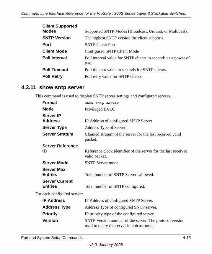
Command Line Interface Reference for the ProSafe 7300S Series Layer-3 Stackable Switches,
Client Supported Modes Supported SNTP Modes (Broadcast, Unicast, or Multicast).SNTP Version The highest SNTP version the client supportsPort SNTP Client PortClient Mode Configured SNTP Client ModePoll Interval Poll interval value for SNTP clients in seconds as a power of
two.Poll Timeout Poll timeout value in seconds for SNTP clients.Poll Retry Poll retry value for SNTP clients.
4.3.11 show sntp serverThis command is used to display SNTP server settings and configured servers.
Format show sntp server
Mode Privileged EXECServer IP Address IP Address of configured SNTP ServerServer Type Address Type of Server.Server Stratum Claimed stratum of the server for the last received valid
packet.Server Reference ID Reference clock identifier of the server for the last received
valid packet.Server Mode SNTP Server mode.Server Max Entries Total number of SNTP Servers allowed.Server Current Entries Total number of SNTP configured.
For each configured server:IP Address IP Address of configured SNTP Server.Address Type Address Type of configured SNTP server.Priority IP priority type of the configured server.Version SNTP Version number of the server. The protocol version
used to query the server in unicast mode.
Port and System Setup Commands 4-15
v3.0, January 2008

Command Line Interface Reference for the ProSafe 7300S Series Layer-3 Stackable Switches,
Port Server Port NumberLast Attempt Time Last server attempt time for the specified server.Last Attempt Status Last server attempt status for the server.Total Unicast Requests Number of requests to the server.Failed Unicast Requests Number of failed requests from server.
4.3.12 clock timezoneWhen using SNTP/NTP time servers to update the switch’s clock, the time data received from the server is based on Coordinated Universal Time (UTC) which is the same as Greenwich Mean Time (GMT). This may not be the time zone in which the switch is located. Use the clock timezone command to configure a time zone specifying the number of hours and optionally the number of minutes difference from UTC. To set the switch clock to UTC, use the no form of the command.
Format clock timezone zone-name +/-hours-offset [+/-minutes-off-set][no] clock timezone
Parameters Zone name A name to associate with the time zoneHours-offset Number of hours difference with UTCMinutes-offset Number of minutes difference with UTC
Mode Global ConfigDefault [no] clock timezone
4-16 Port and System Setup Commands
v3.0, January 2008

Command Line Interface Reference for the ProSafe 7300S Series Layer-3 Stackable Switches,
4.4 MAC Address and MAC Database CommandsThis section describes the commands you use to configure and view information about the system MAC address and the MAC address table.
4.4.1 network mac-addressThis command sets locally administered MAC addresses. The following rules apply:
• Bit 6 of byte 0 (called the U/L bit) indicates whether the address is universally administered (b'0') or locally administered (b'1').
• Bit 7 of byte 0 (called the I/G bit) indicates whether the destination address is an individual address (b'0') or a group address (b'1').
• The second character, of the twelve character macaddr, must be 2, 6, A or E.
A locally administered address must have bit 6 On (b'1') and bit 7 Off (b'0').Format network mac-address <macaddr>Mode Privileged EXEC
4.4.2 network mac-typeThis command specifies whether the switch uses the burned in MAC address or the locally-administered MAC address.
Default burnedinFormat network mac-type {local | burnedin}Mode Privileged EXEC
4.4.2.1 no network mac-typeThis command resets the value of MAC address to its default.
Format no network mac-type Mode Privileged EXE
Port and System Setup Commands 4-17
v3.0, January 2008
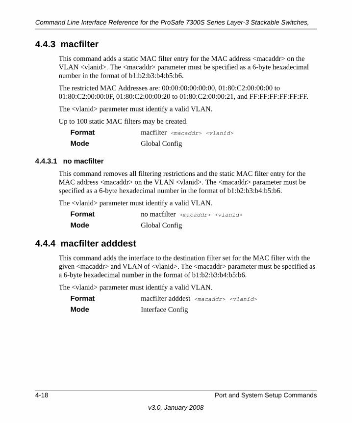
Command Line Interface Reference for the ProSafe 7300S Series Layer-3 Stackable Switches,
4.4.3 macfilterThis command adds a static MAC filter entry for the MAC address <macaddr> on the VLAN <vlanid>. The <macaddr> parameter must be specified as a 6-byte hexadecimal number in the format of b1:b2:b3:b4:b5:b6.
The restricted MAC Addresses are: 00:00:00:00:00:00, 01:80:C2:00:00:00 to 01:80:C2:00:00:0F, 01:80:C2:00:00:20 to 01:80:C2:00:00:21, and FF:FF:FF:FF:FF:FF.
The <vlanid> parameter must identify a valid VLAN.
Up to 100 static MAC filters may be created.Format macfilter <macaddr> <vlanid>Mode Global Config
4.4.3.1 no macfilterThis command removes all filtering restrictions and the static MAC filter entry for the MAC address <macaddr> on the VLAN <vlanid>. The <macaddr> parameter must be specified as a 6-byte hexadecimal number in the format of b1:b2:b3:b4:b5:b6.
The <vlanid> parameter must identify a valid VLAN.Format no macfilter <macaddr> <vlanid>Mode Global Config
4.4.4 macfilter adddestThis command adds the interface to the destination filter set for the MAC filter with the given <macaddr> and VLAN of <vlanid>. The <macaddr> parameter must be specified as a 6-byte hexadecimal number in the format of b1:b2:b3:b4:b5:b6.
The <vlanid> parameter must identify a valid VLAN. Format macfilter adddest <macaddr> <vlanid>Mode Interface Config
4-18 Port and System Setup Commands
v3.0, January 2008

Command Line Interface Reference for the ProSafe 7300S Series Layer-3 Stackable Switches,
4.4.4.1 no macfilter adddestThis command removes a port from the destination filter set for the MAC filter with the given <macaddr> and VLAN of <vlanid>. The <macaddr> parameter must be specified as a 6-byte hexadecimal number in the format of b1:b2:b3:b4:b5:b6.
The <vlanid> parameter must identify a valid VLAN.Format no macfilter adddest <macaddr> <vlanid>Mode Interface Config
4.4.5 macfilter adddest allThis command adds all interfaces to the destination filter set for the MAC filter with the given <macaddr> and VLAN of <vlanid>. The <macaddr> parameter must be specified as a 6-byte hexadecimal number in the format of b1:b2:b3:b4:b5:b6.
The <vlanid> parameter must identify a valid VLAN. Format macfilter adddest allMode Global Config
4.4.5.1 no macfilter adddest allThis command removes all ports from the destination filter set for the MAC filter with the given <macaddr> and VLAN of <vlanid>. The <macaddr> parameter must be specified as a 6-byte hexadecimal number in the format of b1:b2:b3:b4:b5:b6.
The <vlanid> parameter must identify a valid VLAN. Format no macfilter adddest allMode Global Config
4.4.6 macfilter addsrcThis command adds the interface to the source filter set for the MAC filter with the MAC address of <macaddr> and VLAN of <vlanid>. The <macaddr> parameter must be specified as a 6-byte hexadecimal number in the format of b1:b2:b3:b4:b5:b6.
The <vlanid> parameter must identify a valid VLAN. Format macfilter addsrc <macaddr> <vlanid>
Mode Interface Config
Port and System Setup Commands 4-19
v3.0, January 2008

Command Line Interface Reference for the ProSafe 7300S Series Layer-3 Stackable Switches,
4.4.6.1 no macfilter addsrcThis command removes a port from the source filter set for the MAC filter with the MAC address of <macaddr> and VLAN of <vlanid>. The <macaddr> parameter must be specified as a 6-byte hexadecimal number in the format of b1:b2:b3:b4:b5:b6.
The <vlanid> parameter must identify a valid VLAN. Format no macfilter addsrc <macaddr> <vlanid>
Mode Interface Config
4.4.7 macfilter addsrc allThis command adds all interfaces to the source filter set for the MAC filter with the MAC address of <macaddr> and <vlanid>. You must specify the <macaddr> parameter as a 6-byte hexadecimal number in the format of b1:b2:b3:b4:b5:b6. The <vlanid> parameter must identify a valid VLAN.
Format macfilter addsrc all
Mode Global Config
4.4.7.1 no macfilter addsrc allThis command removes a port from the source filter set for the MAC filter with the MAC address of <macaddr> and VLAN of <vlanid>. The <macaddr> parameter must be specified as a 6-byte hexadecimal number in the format of b1:b2:b3:b4:b5:b6.
The <vlanid> parameter must identify a valid VLAN. Format no macfilter addsrc all
Mode Global Config
4-20 Port and System Setup Commands
v3.0, January 2008

Command Line Interface Reference for the ProSafe 7300S Series Layer-3 Stackable Switches,
4.4.8 bridge aging-timeThis command configures the forwarding database address aging timeout in seconds. In an IVL system, the [fdbid | all] parameter is required.
Default 300Format bridge aging-time <10-1,000,000> [fdbid | all]
Mode Global ConfigSeconds The <seconds> parameter must be within the range of 10 to
1,000,000 seconds. Forwarding Database ID The forwarding database ID (fdbid) indicates which for-
warding database's aging timeout is being configured. Use the all option to configure the agetime of all forwarding databases.
4.4.8.1 no bridge aging-timeThis command sets the forwarding database address aging timeout to 300 seconds. In an IVL system, the [fdbid | all] parameter is required.
Format no bridge aging-time [fdbid | all]
Mode Global ConfigForwarding Database ID Fdbid (Forwarding database ID) indicates which forwarding
database's aging timeout is being configured. All is used to configure all forwarding database's agetime.
Port and System Setup Commands 4-21
v3.0, January 2008

Command Line Interface Reference for the ProSafe 7300S Series Layer-3 Stackable Switches,
4.4.9 show forwardingdb agetime This command displays the timeout for address aging. In an IVL system, the [fdbid | all] parameter is required.
Default all Format show forwardingdb agetime [fdbid | all]
Mode Privileged EXECForwarding DB ID Forwarding database ID indicates the forwarding database
whose aging timeout is to be shown. The all option is used to display the aging timeouts associated with all forwarding databases.
Agetime In an IVL system, this parameter displays the address aging timeout for the associated forwarding database.
4.4.10 show mac-address-table multicastThis command displays the Multicast Forwarding Database (MFDB) information. If you enter the command with no parameter, the entire table is displayed. You can display the table entry for one MAC Address by specifying the MAC address as an optional parameter.
Format show mac-address-table multicast <macaddr>
Mode Privileged EXECMAC Address A multicast MAC address for which the switch has forward-
ing and or filtering information. The format is two-digit hexa-decimal numbers separated by colons, for example 01:23:45:67:89:AB. In an IVL system the MAC address will be displayed as a MAC address and VLAN ID combination of 8 bytes.
Type This displays the type of the entry. Static entries are those that are configured by the end user. Dynamic entries are added to the table as a result of a learning process or protocol.
Component The component that is responsible for this entry in the Multi-cast Forwarding Database. Possible values are IGMP Snoop-ing, GMRP, and Static Filtering.
Description The text description of this multicast table entry.
4-22 Port and System Setup Commands
v3.0, January 2008

Command Line Interface Reference for the ProSafe 7300S Series Layer-3 Stackable Switches,
Interfaces The list of interfaces that are designated for forwarding (Fwd:) and filtering (Flt:).
Forwarding Interfaces The resultant forwarding list is derived from combining all
the component’s forwarding interfaces and removing the interfaces that are listed as the static filtering interfaces.
4.4.11 show mac-address-table static This command displays the Static MAC Filtering information for all Static MAC Filters. If you select <all>, all the Static MAC Filters in the system are displayed. If you supply a value for <macaddr>, you must also enter a value for <vlanid>, and the system displays Static MAC Filter information only for that MAC address and VLAN.
Format show mac-address-table static {<macaddr> <vlanid> | all}
Mode Privileged EXECMAC Address Is the MAC Address of the static MAC filter entry.VLAN ID Is the VLAN ID of the static MAC filter entry.Source Port(s) Indicates the source port filter set's slot and port(s).Destination Port(s) Indicates the destination port filter set's slot and port(s).
4.4.12 show mac-address-table statsThis command displays the Multicast Forwarding Database (MFDB) statistics.
Format show mac-address-table stats
Mode Privileged EXECTotal Entries Displays the total number of entries that can possibly be in
the Multicast Forwarding Database table.Most MFDB Entries Ever Used Displays the largest number of entries that have been present
in the Multicast Forwarding Database table. This value is also known as the MFDB high-water mark.
Current Entries Displays the current number of entries in the MFDB.
Port and System Setup Commands 4-23
v3.0, January 2008

Command Line Interface Reference for the ProSafe 7300S Series Layer-3 Stackable Switches,
4.5 DNS Client CommandsThe Domain Name System (DNS) is an Internet directory service. DNS is used to translate domain names to IP addresses. A DNS Client (often referred to as a resolver) uses a defined protocol to obtain resource data from name servers on its network.
The DNS Client component must be globally enabled or disabled. When the client is enabled, it provides a hostname lookup service to other components in the switch. The client contacts one or more DNS servers to resolve a hostname to an IP address. The DNS servers list is configured by providing an IP address for each DNS name server, and server precedence is determined by the order in which the servers are added to this list. A default domain name can be configured, which defines the domain to use when performing a lookup on an unqualified hostname. Static hostname-to-address mappings can be added and removed from the local cache.
The DNS client supports 128 entries in the DNS cache. Any application component requiring a DNS lookup may request services from the DNS client. When the DNS client is administratively disabled the local cache is purged. Changes to the name server configuration do not affect the cache. If a stacking switchover occurs, the new Master unit begins with a cleared cache.
The following applications support domain name in addition to the IP address format:
Radius
DHCP Relay
SNTP
SNMP
TFTP
SYSLOG
Ping
UDP Relay
4-24 Port and System Setup Commands
v3.0, January 2008

Command Line Interface Reference for the ProSafe 7300S Series Layer-3 Stackable Switches,
4.5.1 ip domain-lookupTo enable the IP Domain Naming System (DNS)-based host name-to-address translation, use the ip domain-lookup global configuration command. To disable the DNS, use the no form of this command
Format [no] ip domain-lookup
Mode Global ConfigDefault enabled
4.5.2 ip domain-nameTo define a default domain name (<name>) that the software uses to complete unqualified host names (names without a dotted-decimal domain name), use the ip domain-name global configuration command. To remove default domain name, use the no form of this command.
Default domain used to complete unqualified host names. Do not include the initial period that separates an unqualified name from the domain name.
<name> is a string of 1 to 255 characters.Format ip domain-name name
no ip domain-name
Mode Global Config
4.5.3 ip name-serverTo set the available name servers, use the ip name-server global configuration command. <server-address> is IP addresses of the name server. Up to 8 servers can be defined in one command, or by using multiple commands. The preference of the servers is determined by the order they were entered. To remove a name server, use the no form of this command.
Format [no] ip name-server server-address1 [server-address2 … server-address8]
Mode Global Config
Port and System Setup Commands 4-25
v3.0, January 2008

Command Line Interface Reference for the ProSafe 7300S Series Layer-3 Stackable Switches,
4.5.4 ip hostTo define static host name <name> to IP address <address> mapping in the host cache, use the ip host global configuration command. The <name> string is from 1 to 255 characters. To remove the name-to-address mapping, use the no form of this command.
Format [no] ip host name addressMode Global Config
4.5.5 clear hostTo delete entries from the host name-to-address cache, use the clear host Privileged EXEC command.
Format clear host [name | *]Mode Privileged EXEC Mode
4.5.6 show hostsTo display the default domain name, a list of name server hosts, the static and the cached list of host names and addresses, use the show hosts EXEC command.
Format show hosts [name]Mode Privileged EXEC Mode
4-26 Port and System Setup Commands
v3.0, January 2008

Chapter 5Spanning Tree Protocol Commands
This section describes the spanning tree protocol (STP) commands available in the 7300S Series Stackable Switch CLI. STP helps prevent network loops, duplicate messages, and network instability.
The STP Commands section includes the following topics:
• Section 5.1 “STP Configuration Commands” on page 5-1
• Section 5.2 “STP Show Commands” on page 5-10
The commands in this section are in one of two functional groups:
• Show commands display switch settings, statistics, and other information.
• Configuration commands configure features and options of the switch. For every configuration command, there is a show command that displays the configuration setting.
5.1 STP Configuration CommandsThis section describes the commands you use to configure Spanning Tree Protocol (STP).
5.1.1 spanning-treeThis command sets the spanning-tree operational mode to enabled.
Default enabledFormat spanning-tree
Mode Global Config
Note: STP is enabled by default. If STP is disabled, the system does not generate BPDU messages.
Spanning Tree Protocol Commands 5-1
v3.0, January 2008

Command Line Interface Reference for the ProSafe 7300S Series Layer-3 Stackable Switches,
5.1.1.1 no spanning-treeThis command sets the spanning-tree operational mode to disabled. While disabled, the spanning-tree configuration is retained and can be changed, but is not activated.
Format no spanning-tree
Mode Global Config
5.1.2 spanning-tree bpdumigrationcheckThis command enables BPDU migration check on a given interface. The all option enables BPDU migration check on all interfaces.
Format spanning-tree bpdumigrationcheck {<unit/slot/port> | all}
Mode Global Config
5.1.2.1 no spanning-tree bpdumigrationcheckThis command disables BPDU migration check on a given interface. The all option disables BPDU migration check on all interfaces.
Format no spanning-tree bpdumigrationcheck {<unit/slot/port> | all}
Mode Global Config
5.1.3 spanning-tree configuration nameThis command sets the Configuration Identifier Name for use in identifying the configuration that this switch is currently using. The <name> is a string of up to 32 characters.
Default base MAC address in hexadecimal notationFormat spanning-tree configuration name <name>Mode Global Config
5.1.3.1 no spanning-tree configuration nameThis command resets the Configuration Identifier Name to its default.
Format no spanning-tree configuration name
Mode Global Config
5-2 Spanning Tree Protocol Commands
v3.0, January 2008

Command Line Interface Reference for the ProSafe 7300S Series Layer-3 Stackable Switches,
5.1.4 spanning-tree configuration revisionThis command sets the Configuration Identifier Revision Level for use in identifying the configuration that this switch is currently using. The Configuration Identifier Revision Level is a number in the range of 0 to 65535.
Default 0Format spanning-tree configuration revision <0-65535>Mode Global Config
5.1.4.1 no spanning-tree configuration revisionThis command sets the Configuration Identifier Revision Level for use in identifying the configuration that this switch is currently using to the default value, i.e. 0.
Format no spanning-tree configuration revision
Mode Global Config
5.1.5 spanning-tree edgeportThis command specifies that this port is an Edge Port within the common and internal spanning tree. This allows this port to transition to Forwarding State without delay.
Format spanning-tree edgeport
Mode Interface Config
5.1.5.1 no spanning-tree edgeportThis command specifies that this port is not an Edge Port within the common and internal spanning tree.
Format no spanning-tree edgeport
Mode Interface Config
5.1.6 spanning-tree edgeport allThis command specifies that every port is an Edge Port within the common and internal spanning tree. This allows all ports to transition to Forwarding State without delay.
Format spanning-tree edgeport all
Mode Global Config
Spanning Tree Protocol Commands 5-3
v3.0, January 2008

Command Line Interface Reference for the ProSafe 7300S Series Layer-3 Stackable Switches,
5.1.6.1 no spanning-tree edgeport allThis command disables Edge Port mode for all ports within the common and internal spanning tree.
Format spanning-tree edgeport all
Mode Global Config
5.1.7 spanning-tree forceversionThis command sets the Force Protocol Version parameter to a new value. The Force Protocol Version can be one of the following:
• 802.1d - ST BPDUs are transmitted rather than MST BPDUs (IEEE 802.1d functionality supported)
• 802.1w - RST BPDUs are transmitted rather than MST BPDUs (IEEE 802.1w functionality supported)
• 802.1s - MST BPDUs are transmitted (IEEE 802.1s functionality supported)Default 802.1sFormat spanning-tree forceversion <802.1d | 802.1w |
802.1s>
Mode Global Config
5.1.7.1 no spanning-tree forceversionThis command sets the Force Protocol Version parameter to the default value, i.e. 802.1s.
Format no spanning-tree forceversion
Mode Global Config
5.1.8 spanning-tree forward-timeThis command sets the Bridge Forward Delay parameter to a new value for the common and internal spanning tree. The forward-time value is in seconds within a range of 4 to 30, with the value being greater than or equal to “(Bridge Max Age / 2) + 1”.
Default 15Format spanning-tree forward-time <4-30>Mode Global Config
5-4 Spanning Tree Protocol Commands
v3.0, January 2008

Command Line Interface Reference for the ProSafe 7300S Series Layer-3 Stackable Switches,
5.1.8.1 no spanning-tree forward-timeThis command sets the Bridge Forward Delay parameter for the common and internal spanning tree to the default value of 15.
Format no spanning-tree forward-time
Mode Global Config
5.1.9 spanning-tree hello-timeThis command sets the Admin Hello Time parameter to a new value for the common and internal spanning tree. The hello time <value> is in whole seconds within a range of 1 to 10, with the value being less than or equal to (Bridge Max Age / 2) - 1.
Default 2Format spanning-tree hello-time <1-10>
Mode Interface Config
5.1.9.1 no spanning-tree hello-timeThis command sets the admin Hello Time parameter for the common and internal spanning tree to the default value.
Format no spanning-tree hello-time
Mode Interface Config
5.1.10 spanning-tree max-ageThis command sets the Bridge Max Age parameter to a new value for the common and internal spanning tree. The max-age value is in seconds within a range of 6 to 40, with the value being less than or equal to 2 x (Bridge Forward Delay - 1).
Default 20Format spanning-tree max-age <6-40>Mode Global Config
5.1.10.1 no spanning-tree max-ageThis command sets the Bridge Max Age parameter for the common and internal spanning tree to the default value of 20.
Format no spanning-tree max-age
Mode Global Config
Spanning Tree Protocol Commands 5-5
v3.0, January 2008

Command Line Interface Reference for the ProSafe 7300S Series Layer-3 Stackable Switches,
5.1.11 spanning-tree max-hopsThis command sets the MSTP Max Hops parameter to a new value for the common and internal spanning tree. The max-hops value is a range from 1 to 127.
Default 20Format spanning-tree max-hops <1-127>
Mode Global Config
5.1.11.1 no spanning-tree max-hopsThis command sets the Bridge Max Hops parameter for the common and internal spanning tree to the default value.
Format no spanning-tree max-hops
Mode Global Config
5.1.12 spanning-tree mstThis command sets the Path Cost or Port Priority for this port within the multiple spanning tree instance or in the common and internal spanning tree. If you specify an <mstid> parameter that corresponds to an existing multiple spanning tree instance, the configurations are done for that multiple spanning tree instance. If you specify 0 (defined as the default CIST ID) as the <mstid>, the configurations are done for the common and internal spanning tree instance.
If you specify the cost option, the command sets the path cost for this port within a multiple spanning tree instance or the common and internal spanning tree instance, depending on the <mstid> parameter. You can set the path cost as a number in the range of 1 to 200000000 or auto. If you select auto the path cost value is set based on Link Speed.
If you specify the external-cost option, this command sets the external-path cost for MST instance ‘0’ i.e. CIST instance. You can set the external cost as a number in the range of 1 to 200000000 or auto. If you specify auto, the external path cost value is set based on Link Speed.
If you specify the port-priority option, this command sets the priority for this port within a specific multiple spanning tree instance or the common and internal spanning tree instance, depending on the <mstid> parameter. The port-priority value is a number in the range of 0 to 240 in increments of 16.
Default cost: auto; external-cost: auto; port-priority: 128Format spanning-tree mst <mstid> {{cost <1-200000000> |
auto} |
5-6 Spanning Tree Protocol Commands
v3.0, January 2008

Command Line Interface Reference for the ProSafe 7300S Series Layer-3 Stackable Switches,
{external-cost <1-200000000> | auto}| port-prior-ity <0-240>}
Mode Interface Config
5.1.12.1 no spanning-tree mstThis command sets the Path Cost or Port Priority for this port within the multiple spanning tree instance, or in the common and internal spanning tree to the respective default values. If you specify an <mstid> parameter that corresponds to an existing multiple spanning tree instance, you are configuring that multiple spanning tree instance. If you specify 0 (defined as the default CIST ID) as the <mstid>, you are configuring the common and internal spanning tree instance.
If the you specify cost, this command sets the path cost for this port within a multiple spanning tree instance or the common and internal spanning tree instance, depending on the <mstid> parameter, to the default value, i.e. a path cost value based on the Link Speed.
If you specify external-cost, this command sets the external path cost for this port for mst ‘0’ instance, to the default value, i.e. a path cost value based on the Link Speed.
If you specify port-priority, this command sets the priority for this port within a specific multiple spanning tree instance or the common and internal spanning tree instance, depending on the <mstid> parameter, to the default value, i.e. 128.
Format no spanning-tree mst <mstid> <cost | external-cost | port-priority>
Mode Interface Config
5.1.13 spanning-tree mst instanceThis command adds a multiple spanning tree instance to the switch. The parameter <mstid> is a number within a range of 1 to 4094, that corresponds to the new instance ID to be added. The maximum number of multiple instances supported by the switch is 4.
Format spanning-tree mst instance <mstid>
Mode Global Config
Spanning Tree Protocol Commands 5-7
v3.0, January 2008

Command Line Interface Reference for the ProSafe 7300S Series Layer-3 Stackable Switches,
5.1.13.1 no spanning-tree mst instanceThis command removes a multiple spanning tree instance from the switch and reallocates all VLANs allocated to the deleted instance to the common and internal spanning tree. The parameter <mstid> is a number that corresponds to the desired existing multiple spanning tree instance to be removed.
Format no spanning-tree mst instance <mstid>Mode Global Config
5.1.14 spanning-tree mst priorityThis command sets the bridge priority for a specific multiple spanning tree instance. The parameter <mstid> is a number that corresponds to the desired existing multiple spanning tree instance. The priority value is a number within a range of 0 to 61440 in increments of 4096.
If you specify 0 (defined as the default CIST ID) as the <mstid>, this command sets the Bridge Priority parameter to a new value for the common and internal spanning tree. The bridge priority value is a number within a range of 0 to 61440. The twelve least significant bits are masked according to the 802.1s specification. This causes the priority to be rounded down to the next lower valid priority.
Default 32768Format spanning-tree mst priority <mstid> <0-61440>Mode Global Config
5.1.14.1 no spanning-tree mst priorityThis command sets the bridge priority for a specific multiple spanning tree instance to the default value, i.e. 32768. The parameter <mstid> is a number that corresponds to the desired existing multiple spanning tree instance.
If 0 (defined as the default CIST ID) is passed as the <mstid>, this command sets the Bridge Priority parameter for the common and internal spanning tree to the default value, i.e. 32768.
Format spanning-tree mst priority <mstid>
Mode Global Config
5-8 Spanning Tree Protocol Commands
v3.0, January 2008

Command Line Interface Reference for the ProSafe 7300S Series Layer-3 Stackable Switches,
5.1.15 spanning-tree mst vlanThis command adds an association between a multiple spanning tree instance and a VLAN so that the VLAN is no longer associated with the common and internal spanning tree.
The parameter <mstid> is a number that corresponds to the desired existing multiple spanning tree instance. The <vlanid> corresponds to an existing VLAN ID.
Format spanning-tree mst vlan <mstid> <vlanid>
Mode Global Config
5.1.15.1 no spanning-tree mst vlanThis command removes an association between a multiple spanning tree instance and a VLAN so that the VLAN is again be associated with the common and internal spanning tree. The parameter <mstid> is a number that corresponds to the desired existing multiple spanning tree instance. The <vlanid> corresponds to an existing VLAN ID.
Format no spanning-tree mst vlan <mstid> <vlanid>
Mode Global Config
5.1.16 spanning-tree port modeThis command sets the Administrative Switch Port State for this port to enabled.
Default disabledFormat spanning-tree port mode
Mode Interface Config
5.1.16.1 no spanning-tree port modeThis command sets the Administrative Switch Port State for this port to disabled.
Format no spanning-tree port mode
Mode Interface Config
5.1.17 spanning-tree port mode allThis command sets the Administrative Switch Port State for all ports to enabled.
Default disabledFormat spanning-tree port mode all
Mode Global Config
Spanning Tree Protocol Commands 5-9
v3.0, January 2008

Command Line Interface Reference for the ProSafe 7300S Series Layer-3 Stackable Switches,
5.1.17.1 no spanning-tree port mode allThis command sets the Administrative Switch Port State for all ports to disabled.
Format no spanning-tree port mode all
Mode Global Config
5.1.18 spanning-tree bpduforwardingNormally a switch will not forward Spanning Tree Protocol (STP) BPDU packets if STP is disabled. However, if in some network setup, the user wishes to forward BDPU packets received from other network devices, this command can be used to enable the forwarding.
Default disabledFormat spanning-tree bpduforwarding
Mode Global Config
5.1.18.1 no spanning-tree bpduforwardingThis command will cause the STP BPDU packets received from the network to be dropped if STP is disabled.
Format no spanning-tree bpduforwarding
Mode Global Config
5.2 STP Show CommandsThis section describes the commands you use to view information about STP configuration and status.
5.2.1 show spanning-treeThis command displays spanning tree settings for the common and internal spanning tree, when the optional parameter “brief” is not included in the command. The following details are displayed.
Format show spanning-tree <brief>Modes Privileged EXEC
User EXEC
5-10 Spanning Tree Protocol Commands
v3.0, January 2008

Command Line Interface Reference for the ProSafe 7300S Series Layer-3 Stackable Switches,
Bridge Priority Specifies the bridge priority for the Common and Internal Spanning tree (CST). The value lies between 0 and 61440. It is displayed in multiples of 4096.
Bridge Identifier The bridge identifier for the CST. It is made up using the bridge priority and the base MAC address of the bridge.
Time Since Topology Change Time in seconds.Topology Change Count Number of times changed.Topology Change Boolean value of the Topology Change parameter for the
switch indicating if a topology change is in progress on any port assigned to the common and internal spanning tree.
Designated Root The bridge identifier of the root bridge. It is made up from the bridge priority and the base MAC address of the bridge.
Root Path Cost Value of the Root Path Cost parameter for the common and internal spanning tree.
Root Port Identifier Identifier of the port to access the Designated Root for the
CST.Root Port Max Age Derived value.Root Port Bridge Forward Delay Derived value.Hello Time Configured value of the parameter for the CST.Bridge Hold Time Minimum time between transmission of Configuration
Bridge Protocol Data Units (BPDUs)Bridge Max Hops Bridge max-hops count for the device.CST Regional Root Bridge Identifier of the CST Regional Root. It is made up
using the bridge priority and the base MAC address of the bridge.
Regional Root Path Cost Path Cost to the CST Regional Root.
Spanning Tree Protocol Commands 5-11
v3.0, January 2008

Command Line Interface Reference for the ProSafe 7300S Series Layer-3 Stackable Switches,
Associated FIDs List of forwarding database identifiers currently associated with this instance.
Associated VLANs List of VLAN IDs currently associated with this instance.
When you include the brief keyword, this command displays spanning tree settings for the bridge and the following information appears.
Bridge Priority Configured value.Bridge Identifier The bridge identifier for the selected MST instance. It is
made up using the bridge priority and the base MAC address of the bridge.
Bridge Max Age Configured value.Bridge Max Hops Bridge max-hops count for the device.Bridge Hello Time Configured value.Bridge Forward Delay Configured value.Bridge Hold Time Minimum time between transmission of Configuration
Bridge Protocol Data Units (BPDUs)
5.2.2 show spanning-tree summaryThis command displays spanning tree settings and parameters for the switch. The following details are displayed on execution of the command.
Format show spanning-tree summary
Modes Privileged EXECUser EXEC
Spanning Tree Adminmode Enabled or disabled.Spanning Tree Version Version of 802.1 currently supported (IEEE 802.1s, IEEE
802.1w, or IEEE 802.1d) based upon the Force Protocol Ver-sion parameter.
Configuration Name Identifier used to identify the configuration currently being
used.
5-12 Spanning Tree Protocol Commands
v3.0, January 2008

Command Line Interface Reference for the ProSafe 7300S Series Layer-3 Stackable Switches,
Configuration Revision Level Identifier used to identify the configuration currently being
used.Configuration Digest Key Identifier used to identify the configuration currently being
used.MST Instances List of all multiple spanning tree instances configured on the
switch
5.2.3 show spanning-tree interfaceThis command displays the settings and parameters for a specific switch port within the common and internal spanning tree. The <unit/slot/port> is the desired switch port. The following details are displayed on execution of the command.
Format show spanning-tree interface <unit/slot/port>Modes Privileged EXEC
User EXECHello Time Admin hello time for this port.Port mode Enabled or disabled.Port Up Time Since Counters Last Cleared Time since port was reset, displayed in days, hours, minutes,
and seconds.STP BPDUs Transmitted Spanning Tree Protocol Bridge Protocol Data Units sentSTP BPDUs Received Spanning Tree Protocol Bridge Protocol Data Units received.RST BPDUs Transmitted Rapid Spanning Tree Protocol Bridge Protocol Data Units
sentRST BPDUs Received Rapid Spanning Tree Protocol Bridge Protocol Data Units
received.MSTP BPDUs Transmitted Multiple Spanning Tree Protocol Bridge Protocol Data Units
sent
Spanning Tree Protocol Commands 5-13
v3.0, January 2008

Command Line Interface Reference for the ProSafe 7300S Series Layer-3 Stackable Switches,
MSTP BPDUs Received Multiple Spanning Tree Protocol Bridge Protocol Data Units
received.
5.2.4 show spanning-tree mst port detailedThis command displays the detailed settings and parameters for a specific switch port within a particular multiple spanning tree instance. The parameter <mstid> is a number that corresponds to the desired existing multiple spanning tree instance. The <unit/slot/port> is the desired switch port.
Format show spanning-tree mst port detailed <mstid> <unit/slot/port>
Mode Privileged EXECUser EXEC
MST Instance ID The ID of the existing MST instance.Port Identifier The port identifier for the specified port within the selected
MST instance. It is made up from the port priority and the interface number of the port.
Port Priority The priority for a particular port within the selected MST instance. The port priority is displayed in multiples of 16.
Port Forwarding State Current spanning tree state of this port.Port Role Each enabled MST Bridge Port receives a Port Role for each
spanning tree. The port role is one of the following values: Root Port, Designated Port, Alternate Port, Backup Port, Master Port or Disabled Port
Auto-Calculate Port Path Cost This indicates whether auto calculation for port path cost is
enabled.Port Path Cost Configured value of the Internal Port Path Cost parameter.Auto-Calculate External Port Path Cost This indicates whether auto calculation for external port path
cost is enabled.External Port Path Cost Configured value of the external Port Path Cost parameter.Designated Root The Identifier of the designated root for this port.
5-14 Spanning Tree Protocol Commands
v3.0, January 2008

Command Line Interface Reference for the ProSafe 7300S Series Layer-3 Stackable Switches,
Designated Port Cost Path Cost offered to the LAN by the Designated Port Designated Bridge Bridge Identifier of the bridge with the Designated Port. Designated Port Identifier Port on the Designated Bridge that offers the lowest cost to
the LAN.
If you specify 0 (defined as the default CIST ID) as the <mstid>, this command displays the settings and parameters for a specific switch port within the common and internal spanning tree. The <unit/slot/port> is the desired switch port. In this case, the following are displayed.
Port Identifier The port identifier for this port within the CST.Port Priority The priority of the port within the CST.Port Forwarding State The forwarding state of the port within the CST.Port Role The role of the specified interface within the CST.Port Path Cost The configured path cost for the specified interface.Designated Root Identifier of the designated root for this port within the CST.Designated Port Cost Path Cost offered to the LAN by the Designated Port.Designated Bridge The bridge containing the designated portDesignated Port Identifier Port on the Designated Bridge that offers the lowest cost to
the LAN Topology Change Acknowledgement Value of flag in next Configuration Bridge Protocol Data
Unit (BPDU) transmission indicating if a topology change is in progress for this port.
Hello Time The hello time in use for this port.Edge Port The configured value indicating if this port is an edge port.Edge Port Status The derived value of the edge port status. True if operating as
an edge port; false otherwise.
Spanning Tree Protocol Commands 5-15
v3.0, January 2008

Command Line Interface Reference for the ProSafe 7300S Series Layer-3 Stackable Switches,
Point To Point MAC Status Derived value indicating if this port is part of a point to point
link.
CST Regional Root The regional root identifier in use for this port.CST Port Cost The configured path cost for this port.
5.2.5 show spanning-tree mst port summaryThis command displays the settings of one or all ports within the specified multiple spanning tree instance. The parameter <mstid> indicates a particular MST instance. The parameter {<unit/slot/port> | all} indicates the desired switch port or all ports.
If you specify 0 (defined as the default CIST ID) as the <mstid>, the status summary displays for one or all ports within the common and internal spanning tree.
Format show spanning-tree mst port summary <mstid> {<unit/slot/port> | all}
Modes Privileged EXECUser EXEC
MST Instance ID The MST instance associated with this port.Interface Valid slot and port number separated by forward slashes.Type Currently not used.STP State The forwarding state of the port in the specified spanning tree
instancePort Role The role of the specified port within the spanning tree.Link Status The operational status of the link. Possible values are “Up” or
“Down”.Link Trap The link trap configuration for the specified interface.
5.2.6 show spanning-tree mst summaryThis command displays summary information about all multiple spanning tree instances in the switch. On execution, the following details are displayed.
Format show spanning-tree mst summary
Modes Privileged EXECUser EXEC
5-16 Spanning Tree Protocol Commands
v3.0, January 2008

Command Line Interface Reference for the ProSafe 7300S Series Layer-3 Stackable Switches,
MST Instance ID List List of multiple spanning trees IDs currently configured.For each MSTID: Associated FIDs List of forwarding database identifiers associated with this
instance.Associated VLANs List of VLAN IDs associated with this instance.
5.2.7 show spanning-tree vlanThis command displays the association between a VLAN and a multiple spanning tree instance. The <vlanid> corresponds to an existing VLAN ID.
Format show spanning-tree vlan <vlanid>
Modes Privileged EXECUser EXEC
VLAN Identifier The VLANs associated with the selected MST instance.Associated Instance Identifier for the associated multiple spanning tree instance or
“CST” if associated with the common and internal spanning tree.
Spanning Tree Protocol Commands 5-17
v3.0, January 2008

Command Line Interface Reference for the ProSafe 7300S Series Layer-3 Stackable Switches,
5-18 Spanning Tree Protocol Commands
v3.0, January 2008

Chapter 6VLAN Commands
This section describes the VLAN commands available in the 7300S Series Stackable Switch CLI. VLANs allow users located on different physical networks to be on the same logical network.
The VLAN Commands section includes the following topics:
• Section 6.1 “VLAN Configuration Commands” on page 6-1
• Section 6.2 “VLAN Show Commands” on page 6-12
• Section 6.3 “Double VLAN Commands” on page 6-15
• Section 6.4 “Provisioning (IEEE 802.1p) Commands” on page 6-20
The commands in this section are in one of two functional groups:
• Show commands display switch settings, statistics, and other information.
• Configuration commands configure features and options of the switch. For every configuration command, there is a show command that displays the configuration setting.
6.1 VLAN Configuration CommandsThis section describes the commands you use to configure VLAN settings.
6.1.1 vlan association macThis command associates a MAC address to a VLAN.
Format vlan association mac <macaddr> <vlanid>
Mode VLAN Config
Association options are:Mac Address A MAC address for which the switch has forwarding and/or
filtering information. The format is 6 or 8 two-digit hexadec-
VLAN Commands 6-1
v3.0, January 2008

Command Line Interface Reference for the ProSafe 7300S Series Layer-3 Stackable Switches,
imal numbers that are separated by colons, for example 01:23:45:67:89:AB.
VLAN ID A VLAN Identifier (VID) is associated with each VLAN.
6.1.1.1 no vlan association macThis command removes the association of a MAC address to a VLAN.
Format no vlan association mac <macaddr> <vlanid>
Mode VLAN Config
Association options are the same as for the vlan association mac command, described above.
6.1.2 vlan databaseThis command gives you access to the VLAN Config mode, which allows you to configure VLAN characteristics.
Format vlan database
Mode Privileged EXEC
6.1.3 network mgmt_vlanThis command configures the Management VLAN ID.
Default 1Format network mgmt_vlan <1-4069>
Mode Privileged EXEC
6.1.3.1 no network mgmt_vlanThis command sets the Management VLAN ID to the default.
Note: This command only applies to GSM7300S series models.
Note: This command only applies to GSM7300S series models.
6-2 VLAN Commands
v3.0, January 2008

Command Line Interface Reference for the ProSafe 7300S Series Layer-3 Stackable Switches,
Format no network mgmt_vlan
Mode Privileged EXEC
6.1.4 vlan This command creates a new VLAN and assigns it an ID. The ID is a valid VLAN identification number (ID 1 is reserved for the default VLAN). VLAN range is 2-4094.
Format vlan <2-4094>
Mode VLAN Config
6.1.4.1 no vlan This command deletes an existing VLAN. The ID is a valid VLAN identification number (ID 1 is reserved for the default VLAN). The VLAN range is 2-4094.
Format no vlan <2-4094>
Mode VLAN Config
6.1.5 vlan acceptframeThis command sets the frame acceptance mode per interface. For VLAN Only mode, untagged frames or priority frames received on this interface are discarded. For Admit All mode, untagged frames or priority frames received on this interface are accepted and assigned the value of the interface VLAN ID for this port. With either option, VLAN tagged frames are forwarded in accordance with the IEEE 802.1Q VLAN Specification.
Default allFormat vlan acceptframe {vlanonly | all}
Mode Interface Config
6.1.5.1 no vlan acceptframeThis command sets the frame acceptance mode per interface to Admit All. For Admit All mode, untagged frames or priority frames received on this interface are accepted and assigned the value of the interface VLAN ID for this port. With either option, VLAN tagged frames are forwarded in accordance with the IEEE 802.1Q VLAN Specification.
Format no vlan acceptframe {vlanonly | all}
Mode Interface Config
VLAN Commands 6-3
v3.0, January 2008

Command Line Interface Reference for the ProSafe 7300S Series Layer-3 Stackable Switches,
6.1.6 vlan ingressfilterThis command enables ingress filtering. If ingress filtering is disabled, frames received with VLAN IDs that do not match the VLAN membership of the receiving interface are admitted and forwarded to ports that are members of that VLAN.
Default disabledFormat vlan ingressfilter
Mode Interface Config
6.1.6.1 no vlan ingressfilterThis command disables ingress filtering. If ingress filtering is disabled, frames received with VLAN IDs that do not match the VLAN membership of the receiving interface are admitted and forwarded to ports that are members of that VLAN.
Format no vlan ingressfilter
Mode Interface Config
6.1.7 vlan makestaticThis command changes a dynamically created VLAN (one that is created by GVRP registration) to a static VLAN (one that is permanently configured and defined). The ID is a valid VLAN identification number. VLAN range is 2-4094.
Format vlan makestatic <2-4094>
Mode VLAN Config
6-4 VLAN Commands
v3.0, January 2008

Command Line Interface Reference for the ProSafe 7300S Series Layer-3 Stackable Switches,
6.1.8 vlan nameThis command changes the name of a VLAN. The name is an alphanumeric string of up to 32 characters, and the ID is a valid VLAN identification number. ID range is 1-4094.
Default VLAN ID 1 - default; other VLANS - blank stringFormat vlan name <2-4094> <name>
Mode VLAN Config
6.1.8.1 no vlan nameThis command sets the name of a VLAN to a blank string.
Format no vlan name <2-4094>
Mode VLAN Config
6.1.9 vlan participationThis command configures the degree of participation for a specific interface in a VLAN. The ID is a valid VLAN identification number, and the interface is a valid interface number.
Format vlan participation {exclude | include | auto} <1-4094>
Mode Interface Config
Participation options are: include The interface is always a member of this VLAN. This is
equivalent to registration fixed.exclude The interface is never a member of this VLAN. This is equiv-
alent to registration forbidden.auto The interface is dynamically registered in this VLAN by
GVRP. The interface will not participate in this VLAN unless a join request is received on this interface. This is equivalent to registration normal.
VLAN Commands 6-5
v3.0, January 2008

Command Line Interface Reference for the ProSafe 7300S Series Layer-3 Stackable Switches,
6.1.10 vlan participation allThis command configures the degree of participation for all interfaces in a VLAN. The ID is a valid VLAN identification number.
Format vlan participation all {exclude | include | auto} <1-4094>
Mode Global Config
Participation options are: include The interface is always a member of this VLAN. This is
equivalent to registration fixed.exclude The interface is never a member of this VLAN. This is equiv-
alent to registration forbidden.auto The interface is dynamically registered in this VLAN by
GVRP. The interface will not participate in this VLAN unless a join request is received on this interface. This is equivalent to registration normal.
6.1.11 vlan port acceptframe allThis command sets the frame acceptance mode for all interfaces. The modes defined as follows:
• VLAN Only mode - Untagged frames or priority frames received on this interface are discarded.
• Admit All mode - Untagged frames or priority frames received on this interface are accepted and assigned the value of the interface VLAN ID for this port.
With either option, VLAN tagged frames are forwarded in accordance with the IEEE 802.1Q VLAN Specification.
Default allFormat vlan port acceptframe all {vlanonly | all}
Mode Global Config
6.1.11.1 no vlan port acceptframe allThis command sets the frame acceptance mode for all interfaces to Admit All. For Admit All mode, untagged frames or priority frames received on this interface are accepted and assigned the value of the interface VLAN ID for this port. With either option, VLAN tagged frames are forwarded in accordance with the IEEE 802.1Q VLAN Specification.
6-6 VLAN Commands
v3.0, January 2008

Command Line Interface Reference for the ProSafe 7300S Series Layer-3 Stackable Switches,
Format no vlan port acceptframe all
Mode Global Config
6.1.12 vlan port pvid allThis command changes the VLAN ID for all interface.
Default 1Format vlan port pvid all <1-4094>
Mode Global Config
6.1.12.1 no vlan port pvid allThis command sets the VLAN ID for all interfaces to 1.
Format no vlan port pvid all
Mode Global Config
6.1.13 vlan port tagging allThis command configures the tagging behavior for all interfaces in a VLAN to enabled. If tagging is enabled, traffic is transmitted as tagged frames. If tagging is disabled, traffic is transmitted as untagged frames. The ID is a valid VLAN identification number.
Format vlan port tagging all <1-4094>
Mode Global Config
6.1.13.1 no vlan port tagging allThis command configures the tagging behavior for all interfaces in a VLAN to disabled. If tagging is disabled, traffic is transmitted as untagged frames. The ID is a valid VLAN identification number.
Format no vlan port tagging all
Mode Global Config
VLAN Commands 6-7
v3.0, January 2008

Command Line Interface Reference for the ProSafe 7300S Series Layer-3 Stackable Switches,
6.1.14 vlan port ingressfilter allThis command enables ingress filtering for all ports. If ingress filtering is disabled, frames received with VLAN IDs that do not match the VLAN membership of the receiving interface are admitted and forwarded to ports that are members of that VLAN.
Default disabledFormat vlan port ingressfilter all
Mode Global Config
6.1.14.1 no vlan port ingressfilter allThis command disables ingress filtering for all ports. If ingress filtering is disabled, frames received with VLAN IDs that do not match the VLAN membership of the receiving interface are admitted and forwarded to ports that are members of that VLAN.
Format no vlan port ingressfilter all
Mode 6.1.15 Global Config
6.1.16 vlan protocol groupThis command adds protocol-based VLAN group to the system. The <groupName> is a character string of 1 to 16 characters. When it is created, the protocol group will be assigned a unique number that will be used to identify the group in subsequent commands.
Format vlan protocol group <groupname>
Mode Global Config
6.1.17 vlan protocol group add protocol This command adds the <protocol> to the protocol-based VLAN identified by <groupid>. A group may have more than one protocol associated with it. Each interface and protocol combination can only be associated with one group. If adding a protocol to a group causes any conflicts with interfaces currently associated with the group, this command will fail and the protocol will not be added to the group. The possible values for protocol are ip, arp, and ipx.
Default noneFormat vlan protocol group add protocol <groupid> <proto-
col>
Mode Global Config
6-8 VLAN Commands
v3.0, January 2008

Command Line Interface Reference for the ProSafe 7300S Series Layer-3 Stackable Switches,
6.1.17.1 no vlan protocol group add protocol This command removes the <protocol> from this protocol-based VLAN group that is identified by this <groupid>. The possible values for protocol are ip, arp, and ipx.
Format no vlan protocol group add protocol <groupid> <protocol>
Mode Global Config
6.1.18 vlan protocol group removeThis command removes the protocol-based VLAN group that is identified by this <groupid>.
Format vlan protocol group remove <groupid>
Mode Global Config
6.1.19 protocol groupThis command attaches a <vlanid> to the protocol-based VLAN identified by <groupid>. A group may only be associated with one VLAN at a time, however the VLAN association can be changed.
The referenced VLAN should be created prior to the creation of the protocol-based VLAN except when GVRP is expected to create the VLAN.
Default noneFormat protocol group <groupid> <vlanid>
Mode VLAN Config
6.1.19.1 no protocol groupThis command removes the <vlanid> from this protocol-based VLAN group that is identified by this <groupid>.
Format no protocol group <groupid> <vlanid>
Mode VLAN Config
VLAN Commands 6-9
v3.0, January 2008

Command Line Interface Reference for the ProSafe 7300S Series Layer-3 Stackable Switches,
6.1.20 protocol vlan groupThis command adds the physical interface to the protocol-based VLAN identified by <groupid>. You can associate multiple interfaces with a group, but you can only associate each interface and protocol combination with one group. If adding an interface to a group causes any conflicts with protocols currently associated with the group, this command fails and the interface(s) are not added to the group.
Create the referenced VLAN before you create the protocol-based VLAN except when you configure GVRP to create the VLAN.
Format protocol vlan group <groupid>
Mode Interface Config
6.1.20.1 no protocol vlan groupThis command removes the interface from this protocol-based VLAN group that is identified by this <groupid>.
Format no protocol vlan group <groupid>
Mode Interface Config
6.1.21 protocol vlan group allThis command adds all physical interfaces to the protocol-based VLAN identified by <groupid>. You can associate multiple interfaces with a group, but you can only associate each interface and protocol combination with one group. If adding an interface to a group causes any conflicts with protocols currently associated with the group, this command will fail and the interface(s) will not be added to the group.
Create the referenced VLAN before you create the protocol-based VLAN except when you configure GVRP to create the VLAN.
Format protocol vlan group all <groupid>
Mode Global Config
6.1.21.1 no protocol vlan group allThis command removes all interfaces from this protocol-based VLAN group that is identified by this <groupid>.
Format no protocol vlan group all <groupid>
Mode Global Config
6-10 VLAN Commands
v3.0, January 2008

Command Line Interface Reference for the ProSafe 7300S Series Layer-3 Stackable Switches,
6.1.22 vlan pvidThis command changes the VLAN ID per interface. When an untagged packet comes to the switch, it will be tagged with the PVID value as the VLAN ID for further processing. By default, every port belongs to VLAN 1 and the PVID value is set to 1.
Default 1Format vlan pvid <1-4094>
Mode Interface Config
6.1.22.1 no vlan pvidThis command sets the VLAN ID per interface to 1.
Format no vlan pvid
Mode Interface Config
6.1.23 vlan taggingThis command configures the tagging behavior for a specific interface in a VLAN to enabled. If tagging is enabled, traffic is transmitted as tagged frames. If tagging is disabled, traffic is transmitted as untagged frames. The ID is a valid VLAN identification number.
Format vlan tagging <1-4094>
Mode Interface Config
6.1.23.1 no vlan taggingThis command configures the tagging behavior for a specific interface in a VLAN to disabled. If tagging is disabled, traffic is transmitted as untagged frames. The ID is a valid VLAN identification number.
Format no vlan tagging <1-4094>
Mode Interface Config
VLAN Commands 6-11
v3.0, January 2008

Command Line Interface Reference for the ProSafe 7300S Series Layer-3 Stackable Switches,
6.2 VLAN Show CommandsThis section describes the commands you use to view VLAN settings.
6.2.1 show vlanThis command displays a list of all configured VLANs.
Format show vlan
Modes Privileged EXECUser EXEC
VLAN ID There is a VLAN Identifier (vlanid) associated with each VLAN. The range of the VLAN ID is 1 to 4094.
VLAN Name A string associated with this VLAN as a convenience. It can be up to 32 alphanumeric characters long, including blanks. The default is blank. VLAN ID 1 always has a name of “Default.” This field is optional.
VLAN Type Type of VLAN, which can be Default (VLAN ID = 1) or static (one that is configured and permanently defined), or a Dynamic (one that is created by GVRP registration).
6.2.2 show vlan <vlan_id>This command displays detailed information, including interface information, for a specific VLAN. The ID is a valid VLAN identification number.
Format show vlan <vlanid>
Modes Privileged EXECUser EXEC
VLAN ID There is a VLAN Identifier (VID) associated with each VLAN. The range of the VLAN ID is 1 to 4094.
VLAN Name A string associated with this VLAN as a convenience. It can be up to 32 alphanumeric characters long, including blanks. The default is blank. VLAN ID 1 always has a name of “Default.” This field is optional.
VLAN Type Type of VLAN, which can be Default (VLAN ID = 1) or static (one that is configured and permanently defined), or Dynamic (one that is created by GVRP registration).
6-12 VLAN Commands
v3.0, January 2008

Command Line Interface Reference for the ProSafe 7300S Series Layer-3 Stackable Switches,
Interface Valid slot and port number separated by forward slashes. It is possible to set the parameters for all ports by using the selec-tors on the top line.
Current Determines the degree of participation of this port in this VLAN. The permissible values are: Include - This port is always a member of this VLAN. This is equivalent to registration fixed in the IEEE 802.1Q standard. Exclude - This port is never a member of this VLAN. This is equivalent to registration forbidden in the IEEE 802.1Q stan-dard. Autodetect - Specifies to allow the port to be dynamically registered in this VLAN via GVRP. The port will not partici-pate in this VLAN unless a join request is received on this port. This is equivalent to registration normal in the IEEE 802.1Q standard.
Configured Determines the configured degree of participation of this port in this VLAN. The permissible values are: Include - This port is always a member of this VLAN. This is equivalent to registration fixed in the IEEE 802.1Q standard. Exclude - This port is never a member of this VLAN. This is equivalent to registration forbidden in the IEEE 802.1Q stan-dard. Autodetect - Specifies to allow the port to be dynamically registered in this VLAN via GVRP. The port will not partici-pate in this VLAN unless a join request is received on this port. This is equivalent to registration normal in the IEEE 802.1Q standard.
Tagging Select the tagging behavior for this port in this VLAN. Tagged - specifies to transmit traffic for this VLAN as tagged frames. Untagged - specifies to transmit traffic for this VLAN as untagged frames.
VLAN Commands 6-13
v3.0, January 2008

Command Line Interface Reference for the ProSafe 7300S Series Layer-3 Stackable Switches,
6.2.3 show vlan association macThis command displays the VLAN associated with a specific configured MAC address. If no MAC address is specified, the VLAN associations of all the configured MAC addresses are displayed.
Format show vlan association mac [<macaddr>]
Modes Privileged EXECUser EXEC
Mac Address A MAC address for which the switch has forwarding and or filtering information. The format is 6 or 8 two-digit hexadec-imal numbers that are separated by colons, for example 01:23:45:67:89:AB.
VLAN ID There is a VLAN Identifier (VID) associated with each VLAN.
6.2.4 show vlan portThis command displays VLAN port information.
Format show vlan port {<unit/slot/port> | all}
Modes Privileged EXECUser EXEC
Interface Valid slot and port number separated by forward slashes. It is possible to set the parameters for all ports by using the selec-tors on the top line.
Port VLAN ID The VLAN ID that this port will assign to untagged frames or priority tagged frames received on this port. The value must be for an existing VLAN. The factory default is 1.
Acceptable Frame Types Specifies the types of frames that may be received on this
port. The options are 'VLAN only' and 'Admit All'. When set to 'VLAN only', untagged frames or priority tagged frames received on this port are discarded. When set to 'Admit All', untagged frames or priority tagged frames received on this
Note: This command only applies to GSM7300S series models.
6-14 VLAN Commands
v3.0, January 2008

Command Line Interface Reference for the ProSafe 7300S Series Layer-3 Stackable Switches,
port are accepted and assigned the value of the Port VLAN ID for this port. With either option, VLAN tagged frames are forwarded in accordance to the 802.1Q VLAN specification.
Ingress Filtering May be enabled or disabled. When enabled, the frame is dis-carded if this port is not a member of the VLAN with which this frame is associated. In a tagged frame, the VLAN is iden-tified by the VLAN ID in the tag. In an untagged frame, the VLAN is the Port VLAN ID specified for the port that received this frame. When disabled, all frames are forwarded in accordance with the 802.1Q VLAN bridge specification. The factory default is disabled.
GVRP May be enabled or disabled.Default Priority The 802.1p priority assigned to tagged packets arriving on
the port.
6.3 Double VLAN CommandsThis section describes the commands you use to configure double VLAN (DVLAN). Double VLAN tagging is a way to pass VLAN traffic from one customer domain to another through a Metro Core in a simple and cost effective manner. The additional tag on the traffic helps differentiate between customers in the MAN while preserving the VLAN identification of the individual customers when they enter their own 802.1Q domain.
6.3.1 dvlan-tunnel customer-idThis command configures the customer identification for the Double VLAN tunnel on the specified interface. The customer ID may have the value 0 to 4095, and the default is 0.
Default 0Format dvlan-tunnel customer-id <0-4095>
Mode Interface Config
6.3.1.1 no dvlan-tunnel customer-idThis command configures the customer identification for the Double VLAN tunnel on the specified interface to its default value.
Format no dvlan-tunnel customer-id
Mode Interface Config
VLAN Commands 6-15
v3.0, January 2008

Command Line Interface Reference for the ProSafe 7300S Series Layer-3 Stackable Switches,
6.3.2 dvlan-tunnel etherTypeThis command configures the ether-type for the specified interface. The ether-type may have the values of 802.1Q, vMAN, or custom. If the ether-type has a value of custom, the optional value of the custom ether type must be set to a value from 0 to 65535.
Default vmanFormat dvlan-tunnel etherType <802.1Q | vman | custom>
[0-65535]
Mode Interface Config
6.3.2.1 no dvlan-tunnel etherTypeThis command configures the ether-type for the specified interface to its default value.
Format no dvlan-tunnel etherType
Mode Interface Config
6.3.3 mode dot1q-tunnelThis command is used to enable Double VLAN Tunneling on the specified interface.
Default disabledFormat mode dot1q-tunnel
Mode Interface Config
6.3.3.1 no mode dot1q-tunnelThis command is used to disable Double VLAN Tunneling on the specified interface. By default, Double VLAN Tunneling is disabled.
Format no mode dot1q-tunnel
Mode Interface Config
6.3.4 mode dvlan-tunnelUse this command to enable Double VLAN Tunneling on the specified interface.
Note: When you use the mode dvlan-tunnel command on an interface, it becomes a service provider port. Ports that do not have double VLAN tunneling enabled are customer ports.
6-16 VLAN Commands
v3.0, January 2008

Command Line Interface Reference for the ProSafe 7300S Series Layer-3 Stackable Switches,
Default disabledFormat mode dvlan-tunnel
Mode Interface Config
6.3.4.1 no mode dvlan-tunnelThis command is used to disable Double VLAN Tunneling on the specified interface. By default, Double VLAN Tunneling is disabled.
Format no mode dvlan-tunnel
Mode Interface Config
VLAN Commands 6-17
v3.0, January 2008

Command Line Interface Reference for the ProSafe 7300S Series Layer-3 Stackable Switches,
6.3.5 show dot1q-tunnelThis command displays all interfaces enabled for Double VLAN Tunneling.
Format show dot1q-tunnel
Modes Privileged EXECUser EXEC
Interface Valid slot and port number separated by forward slashes.
6.3.6 show dot1q-tunnel interfaceThis command displays detailed information about Double VLAN Tunneling for the specified interface.
Format show dot1q-tunnel interface [<unit/slot/port> | all]
Modes Privileged EXECUser EXEC
Interface Valid slot and port number separated by forward slashes.Mode This field specifies the administrative mode through which
Double VLAN Tunneling can be enabled or disabled. The default value for this field is disabled.
Customer Id This is a 12-bit customer ID which will be used as the last 12 bits of the Double VLAN Tunnel. The valid range for a cus-tomer ID is 0 to 4095.
EtherType This field represents a 2-byte hex EtherType to be used as the first 16 bits of the DVLAN tunnel. There are three different EtherType tags. The first is 802.1Q, which represents the commonly used value of 0x8100. The second is vMAN, which represents the commonly used value of 0x88A8. If EtherType is not one of these two values, then it is a custom tunnel value, representing any value in the range of 0 to 65535.
6-18 VLAN Commands
v3.0, January 2008

Command Line Interface Reference for the ProSafe 7300S Series Layer-3 Stackable Switches,
6.3.7 show dvlan-tunnelThis command displays all interfaces enabled for Double VLAN Tunneling.
Format show dvlan-tunnel
Modes Privileged EXECUser EXEC
Interface Valid slot and port number separated by forward slashes.
6.3.8 show dvlan-tunnel interfaceThis command displays detailed information about Double VLAN Tunneling for the specified interface. Use the “all” option to see information about all the interfaces.
Format show dvlan-tunnel interface [<unit/slot/port> | all]
Modes Privileged EXEC User EXEC
Interface Valid slot and port number separated by forward slashes.Mode This field specifies the administrative mode through which
Double VLAN Tunneling can be enabled or disabled. The default value for this field is disabled.
Customer Id This is a 12-bit customer ID which will be used as the last 12 bits of the DVLAN Tunnel. The valid range for a customer ID is 0 to 4095.
EtherType This field represents a 2-byte hex EtherType to be used as the first 16 bits of the DVLAN tunnel. There are three different EtherType tags. The first is 802.1Q, which represents the commonly used value of 0x8100. The second is vMAN, which represents the commonly used value of 0x88A8. If EtherType is not one of these two values, then it is a custom tunnel value, representing any value in the range of 0 to 65535.
VLAN Commands 6-19
v3.0, January 2008

Command Line Interface Reference for the ProSafe 7300S Series Layer-3 Stackable Switches,
6.4 Provisioning (IEEE 802.1p) CommandsThis section describes the commands you use to configure provisioning, which allows you to prioritize ports.
6.4.1 vlan port priority allThis command configures the port priority assigned for untagged packets for all ports presently plugged into the device. The range for the priority is 0-7. Any subsequent per port configuration will override this configuration setting.
Format vlan port priority all <priority>
Mode Global Config
6.4.2 vlan priorityThis command configures the default 802.1p port priority assigned for untagged packets for a specific interface. The range for the priority is 0-7
Default 0Format vlan priority <priority>
Mode Interface Config
6-20 VLAN Commands
v3.0, January 2008

Chapter 7DHCP Commands
This section describes the DHCP commands available in the 7300S Series Stackable Switch CLI. DHCP automatically allocates and manages client TCP/ IP configurations. DHCP uses UDP as its transport protocol and supports a number of features that facilitate in administration address allocations.
The DHCP Server Commands section includes the following topics:
• Section 7.1 “DHCP Server Commands (DHCP Config Pool Mode)” on page 7-2
• Section 7.2 “DHCP Server Commands (Global Config Mode)” on page 7-9
• Section 7.3 “DHCP Server Clear and Show Commands” on page 7-12
• Section 7.4 “DHCP and BOOTP Relay Commands” on page 7-15
The commands in this section are in one of three functional groups:
• Configuration Commands are used to configure features and options of the switch. For every configuration command there is a show command that will display the configuration setting.
• Show commands are used to display switch settings, statistics and other information.
• Clear commands clear some or all of the settings to factory defaults.
DHCP Commands 7-1
v3.0, January 2008

Command Line Interface Reference for the ProSafe 7300S Series Layer-3 Stackable Switches,
7.1 DHCP Server Commands (DHCP Config Pool Mode)This section describes the commands you to configure the DHCP server settings for the switch.
7.1.1 ip dhcp poolThis command configures a DHCP address pool name on a DHCP server and enters DHCP pool configuration mode.
Default noneFormat ip dhcp pool <name>
Mode Global Config
7.1.1.1 no ip dhcp poolThis command removes the DHCP address pool. The name should be previously configured pool name.
Format no ip dhcp pool <name>
Mode Global Config
7.1.2 client-identifierThis command specifies the unique identifier for a DHCP client. Unique-identifier is a valid notation in hexadecimal format. In some systems, such as Microsoft DHCP clients, the client identifier is required instead of hardware addresses. The unique-identifier is a concatenation of the media type and the MAC address. For example, the Microsoft client identifier for Ethernet address c819.2488.f177 is 01c8.1924.88f1.77 where 01 represents the Ethernet media type. For more information, refer to the “Address Resolution Protocol Parameters” section of RFC 1700, Assigned Numbers for a list of media type codes.
Default noneFormat client-identifier <uniqueidentifier>
Mode DHCP Pool Config
Note: The CLI mode changes to DHCP Pool Config mode when you successfully execute this command.
7-2 DHCP Commands
v3.0, January 2008

Command Line Interface Reference for the ProSafe 7300S Series Layer-3 Stackable Switches,
7.1.2.1 no client-identifierThis command deletes the client identifier.
Format no client-identifier
Mode DHCP Pool Config
7.1.3 client-nameThis command specifies the name for a DHCP client. Name is a string consisting of standard ASCII characters.
Default noneFormat client-name <name>
Mode DHCP Pool Config
7.1.3.1 no client-nameThis command removes the client name.
Format no client-name
Mode DHCP Pool Config
7.1.4 default-routerThis command specifies the default router list for a DHCP client. {address1, address2… address8} are valid IP addresses, each made up of four decimal bytes ranging from 0 to 255. IP address 0.0.0.0 is invalid.
Default noneFormat default-router <address1>
[<address2>....<address8>]
Mode DHCP Pool Config
7.1.4.1 no default-routerThis command removes the default router list.
Format no default-router
Mode DHCP Pool Config
DHCP Commands 7-3
v3.0, January 2008
Command Line Interface Reference for the ProSafe 7300S Series Layer-3 Stackable Switches,
7.1.5 dns-serverThis command specifies the IP servers available to a DHCP client. Address parameters are valid IP addresses; each made up of four decimal bytes ranging from 0 to 255. IP address 0.0.0.0 is invalid.
Default noneFormat dns-server <address1> [<address2>....<address8>]
Mode DHCP Pool Config
7.1.5.1 no dns-serverThis command removes the DNS Server list.
Format no dns-server
Mode DHCP Pool Config
7.1.6 hardware-addressThis command specifies the hardware address of a DHCP client. Hardware-address is the MAC address of the hardware platform of the client consisting of 6 bytes in dotted hexadecimal format. Type indicates the protocol of the hardware platform. It is 1 for 10 MB Ethernet and 6 for IEEE 802.
Default ethernetFormat hardware-address <hardwareaddress> [type]
Mode DHCP Pool Config
7.1.6.1 no hardware-addressThis command removes the hardware address of the DHCP client.
Format no hardware-address
Mode DHCP Pool Config
7-4 DHCP Commands
v3.0, January 2008

Command Line Interface Reference for the ProSafe 7300S Series Layer-3 Stackable Switches,
7.1.7 hostThis command specifies the IP address and network mask for a manual binding to a DHCP client. Address and Mask are valid IP addresses; each made up of four decimal bytes ranging from 0 to 255. IP address 0.0.0.0 is invalid. The prefix-length is an integer from 0 to 32
Default noneFormat host <address> [mask | prefix-length]
Mode DHCP Pool Config
7.1.7.1 no hostThis command removes the IP address of the DHCP client.
Format no host
Mode DHCP Pool Config
7.1.8 leaseThis command configures the duration of the lease for an IP address that is assigned from a DHCP server to a DHCP client. The overall lease time should be between 1-86400 minutes. If infinite is specified, lease is set for 60 days. Days is an integer from 0 to 59. Hours is an integer from 0 to 1439. Minutes is an integer from 0 to 86399.
Default 1 (day)Format lease {[<days> [hours] [minutes]] | [infinite]}
Mode DHCP Pool Config
7.1.8.1 no leaseThis command restores the default value of the lease time for DHCP Server.
Format no lease
Mode DHCP Pool Config
DHCP Commands 7-5
v3.0, January 2008
Command Line Interface Reference for the ProSafe 7300S Series Layer-3 Stackable Switches,
7.1.9 networkUse this command to configure the subnet number and mask for a DHCP address pool on the server. Network-number is a valid IP address, made up of four decimal bytes ranging from 0 to 255. IP address 0.0.0.0 is invalid. Mask is the IP subnet mask for the specified address pool. The prefix-length is an integer from 0 to 32.
Default noneFormat network <networknumber> [mask | prefixlength]
Mode DHCP Pool Config
7.1.9.1 no networkThis command removes the subnet number and mask.
Format no network
Mode DHCP Pool Config
7.1.10 bootfileThe command specifies the name of the default boot image for a DHCP client. The <filename> specifies the boot image file.
Default noneFormat bootfile <filename>
Mode DHCP Pool Config
7.1.10.1 no bootfileThis command deletes the boot image name.
Format no bootfile
Mode DHCP Pool Config
7.1.11 domain-nameThis command specifies the domain name for a DHCP client. The <domain> specifies the domain name string of the client.
Default noneFormat domain-name <domain>
Mode DHCP Pool Config
7-6 DHCP Commands
v3.0, January 2008

Command Line Interface Reference for the ProSafe 7300S Series Layer-3 Stackable Switches,
7.1.11.1 no domain-nameThis command removes the domain name.
Format no domain-name
Mode DHCP Pool Config
7.1.12 netbios-name-serverThis command configures NetBIOS Windows Internet Naming Service (WINS) name servers that are available to DHCP clients.
One IP address is required, although one can specify up to eight addresses in one command line. Servers are listed in order of preference (address1 is the most preferred server, address2 is the next most preferred server, and so on).
Default noneFormat netbios-name-server <address>
[<address2>...<address8>]
Mode DHCP Pool Config
7.1.12.1 no netbios-name-serverThis command removes the NetBIOS name server list.
Format no netbios-name-server
Mode DHCP Pool Config
7.1.13 netbios-node-typeThe command configures the NetBIOS node type for Microsoft Dynamic Host Configuration Protocol (DHCP) clients.type Specifies the NetBIOS node type. Valid types are:
• b-node—Broadcast
• p-node—Peer-to-peer
• m-node—Mixed
• h-node—Hybrid (recommended)Default noneFormat netbios-node-type <type>
Mode DHCP Pool Config
DHCP Commands 7-7
v3.0, January 2008

Command Line Interface Reference for the ProSafe 7300S Series Layer-3 Stackable Switches,
7.1.13.1 no netbios-node-typeThis command removes the NetBIOS node Type.
Format no netbios-node-type
Mode DHCP Pool Config
7.1.14 next-serverThis command configures the next server in the boot process of a DHCP client.
Address is the IP address of the next server in the boot process, which is typically a TFTP server.
Default inbound interface helper addressesFormat next-server <address>
Mode DHCP Pool Config
7.1.14.1 no next-serverThis command removes the boot server list.
Format no next-server
Mode DHCP Pool Config
7.1.15 optionThe command configures DHCP Server options. The <code> parameter specifies the DHCP option code. Ascii string specifies an NVT ASCII character string. ASCII character strings that contain white space must be delimited by quotation marks. Hex string specifies hexadecimal data. in hexadecimal character strings is two hexadecimal digits—each byte can be separated by a period, colon, or white space.
Example:a3:4f:22:0c / a3 4f 22 0c / a34f.220c.9fed Default noneFormat option <code> {ascii string | hex <string1>
[<string2>...<string8>] | ip <address1> [<address2>...<address8>]}
Mode DHCP Pool Config
7-8 DHCP Commands
v3.0, January 2008

Command Line Interface Reference for the ProSafe 7300S Series Layer-3 Stackable Switches,
7.1.15.1 no optionThis command removes the options.
Format no option <code>
Mode DHCP Pool Config
7.2 DHCP Server Commands (Global Config Mode)This section describes the commands you to configure the DHCP server settings for the switch. You must be in Global Config mode to execute these commands.
7.2.1 ip dhcp excluded-addressThis command specifies the IP addresses that a DHCP server should not assign to DHCP clients. Low-address and high-address are valid IP addresses; each made up of four decimal bytes ranging from 0 to 255. IP address 0.0.0.0 is invalid.
Default noneFormat ip dhcp excluded-address <lowaddress> [highad-
dress]
Mode Global Config
7.2.1.1 no ip dhcp excluded-addressThis command removes the excluded IP addresses for a DHCP client. Low-address and high-address are valid IP addresses; each made up of four decimal bytes ranging from 0 to 255. IP address 0.0.0.0 is invalid.
Format no ip dhcp excluded-address <lowaddress> [highad-dress]
Mode Global Config
DHCP Commands 7-9
v3.0, January 2008

Command Line Interface Reference for the ProSafe 7300S Series Layer-3 Stackable Switches,
7.2.2 ip dhcp ping packetsThis command is used to specify the number, in a range from 2-10, of packets a DHCP server sends to a pool address as part of a ping operation. By default the number of packets sent to a pool address is 2 (the smallest allowed number when sending packets). Setting the number of packets to 0 disables this command.
Default 2Format ip dhcp ping packets <0,2-10>
Mode Global Config
7.2.2.1 no ip dhcp ping packetsThis command prevents the server from pinging pool addresses and sets the number of packets to 0.
Default 0Format no ip dhcp ping packets
Mode Global Config
7.2.3 service dhcpThis command enables the DHCP server.
Default disabledFormat service dhcp
Mode Global Config
7.2.3.1 no service dhcpThis command disables the DHCP server.
Format no service dhcp
Mode Global Config
Note: The no form of this command sets the number of packets sent to a pool address to 0 and therefore prevents the server from pinging pool addresses.
7-10 DHCP Commands
v3.0, January 2008

Command Line Interface Reference for the ProSafe 7300S Series Layer-3 Stackable Switches,
7.2.4 ip dhcp bootp automaticThis command enables the allocation of the addresses to the bootp client. The addresses are from the automatic address pool.
Default disabledFormat ip dhcp bootp automatic
Mode Global Config
7.2.4.1 no ip dhcp bootp automaticThis command disables the allocation of the addresses to the bootp client. The address are from the automatic address pool.
Format no ip dhcp bootp automatic
Mode Global Config
7.2.5 ip dhcp conflict loggingThis command enables conflict logging on DHCP server.
Default enabledFormat ip dhcp conflict logging
Mode Global Config
7.2.5.1 no ip dhcp conflict loggingThis command disables conflict logging on DHCP server.
Format no ip dhcp conflict logging
Mode Global Config
DHCP Commands 7-11
v3.0, January 2008

Command Line Interface Reference for the ProSafe 7300S Series Layer-3 Stackable Switches,
7.3 DHCP Server Clear and Show CommandsThis section describes the commands you to delete various DHCP information and the commands you use to view DHCP configuration information and statistics.
7.3.1 clear ip dhcp bindingThis command deletes an automatic address binding from the DHCP server database. If “*” is specified, the bindings corresponding to all the addresses are deleted. <address> is a valid IP address made up of four decimal bytes ranging from 0 to 255. IP address 0.0.0.0 is invalid.
Default noneFormat clear ip dhcp binding {address | *}
Mode Privileged EXEC
7.3.2 clear ip dhcp server statisticsThis command clears DHCP server statistics counters.
Format clear ip dhcp server statistics
Mode Privileged EXEC
7.3.3 clear ip dhcp conflictThe command is used to clear an address conflict from the DHCP Server database. The server detects conflicts using a ping. DHCP server clears all conflicts If the asterisk (*) character is used as the address parameter.
Default noneFormat clear ip dhcp conflict {<address> | *}
Mode Privileged EXEC
7.3.4 show ip dhcp bindingThis command displays address bindings for the specific IP address on the DHCP server. If no IP address is specified, the bindings corresponding to all the addresses are displayed.
Format show ip dhcp binding [address]
Modes Privileged EXECUser EXEC
7-12 DHCP Commands
v3.0, January 2008

Command Line Interface Reference for the ProSafe 7300S Series Layer-3 Stackable Switches,
IP address The IP address of the client. Hardware Address The MAC Address or the client identifier.Lease expiration The lease expiration time of the IP Address assigned to the
client. Type The manner in which IP Address was assigned to the client.
7.3.5 show ip dhcp global configurationThis command displays address bindings for the specific IP address on the DHCP server. If no IP address is specified, the bindings corresponding to all the addresses are displayed.
Format show ip dhcp global configuration
Modes Privileged EXECUser EXEC
Service DHCP The field to display the status of dhcp protocol.Number of Ping Packets The maximum number of Ping Packets that will be sent to
verify that an ip address id not already assigned.Conflict Logging Shows whether conflict logging is enabled or disabled.BootP Automatic Shows whether BootP for dynamic pools is enabled or dis-
abled.
7.3.6 show ip dhcp pool configurationThis command displays pool configuration. If all is specified, configuration for all the pools is displayed.
Format show ip dhcp pool configuration {<name> | all}
Modes Privileged EXECUser EXEC
Pool Name The name of the configured pool. Pool Type The pool type.Lease Time The lease expiration time of the IP Address assigned to the
client. DNS Servers The list of DNS servers available to the DHCP client Default Routers The list of the default routers available to the DHCP client
DHCP Commands 7-13
v3.0, January 2008

Command Line Interface Reference for the ProSafe 7300S Series Layer-3 Stackable Switches,
The following additional field is displayed for Dynamic pool type:Network The network number and the mask for the DHCP address
pool.
The following additional fields are displayed for Manual pool type:Client Name The name of a DHCP client.Client Identifier The unique identifier of a DHCP client.Hardware Address The hardware address of a DHCP client. Hardware Address Type The protocol of the hardware platform. Host The IP address and the mask for a manual binding to a DHCP
client.
7.3.7 show ip dhcp server statisticsThis command displays DHCP server statistics.
Format show ip dhcp server statistics
Modes Privileged EXECUser EXEC
Automatic Bindings The number of IP addresses that have been automatically
mapped to the MAC addresses of hosts that are found in the DHCP database.
Expired Bindings The number of expired leases. Malformed Bindings The number of truncated or corrupted messages that were
received by the DHCP server.
Message Received:DHCP DISCOVER The number of DHCPDISCOVER messages the server has
received.DHCP REQUEST The number of DHCPREQUEST messages the server has
received.DHCP DECLINE The number of DHCPDECLINE messages the server has
received.
7-14 DHCP Commands
v3.0, January 2008

Command Line Interface Reference for the ProSafe 7300S Series Layer-3 Stackable Switches,
DHCP RELEASE The number of DHCPRELEASE messages the server has received.
DHCP INFORM The number of DHCPINFORM messages the server has received.
Message Sent:DHCP OFFER The number of DHCPOFFER messages the server sent.DHCP ACK The number of DHCPACK messages the server sent.DHCP NACK The number of DHCPNACK messages the server sent.
7.3.8 show ip dhcp conflictThis command displays address conflicts logged by the DHCP Server. If no IP address is specified, all the conflicting addresses are displayed.
Format show ip dhcp conflict [ip-address]
Modes Privileged EXEC User EXEC
IP address The IP address of the host as recorded on the DHCP server.Detection Method The manner in which the IP address of the hosts were found
on the DHCP ServerDetection time The time when the conflict was found.
7.4 DHCP and BOOTP Relay CommandsThis section describes the commands you use to configure BootP/DHCP Relay on the switch. A DHCP relay agent operates at Layer 3 and forwards DHCP requests and replies between clients and servers when they are not on the same physical subnet.
DHCP Commands 7-15
v3.0, January 2008
Command Line Interface Reference for the ProSafe 7300S Series Layer-3 Stackable Switches,
7.4.1 ip dhcp relay information optionThis command enables option 82 (RFC 3046) for BootP/DHCP Relay on the system. Once enabled, the DHCP request forwarded to the DHCP server will contain two optional fields: Circuit ID and Remote ID. The circuit ID option contains the port information where the DHCP client request originated. The remote ID option contains the MAC address of the relay agent (the switch management CPU's own MAC address).
Default disabledFormat ip dhcp relay information option
Mode Global Config
7.4.1.1 no ip dhcp relay information optionThis command disables the relay information option mode for BootP/DHCP Relay on the system.
Format no ip dhcp relay information option
Mode Global Config
7.4.2 bootpdhcprelayThis command enables the forwarding of relay requests for BootP/DHCP Relay on the system.
Default disabledFormat bootpdhcprelay
Mode Global Config
7.4.2.1 no bootpdhcprelay enableThis command disables the forwarding of relay requests for BootP/DHCP Relay on the system.
Format no bootpdhcprelay enable
Mode Global Config
7-16 DHCP Commands
v3.0, January 2008

Command Line Interface Reference for the ProSafe 7300S Series Layer-3 Stackable Switches,
7.4.3 bootpdhcprelay maxhopcount This command configures the maximum allowable relay agent hops for BootP/DHCP Relay on the system. The <hops> parameter has a range of 1 to 16.
Default 4Format bootpdhcprelay maxhopcount <1-16>
Mode Global Config
7.4.3.1 no bootpdhcprelay maxhopcount This command configures the default maximum allowable relay agent hops for BootP/DHCP Relay on the system.
Format no bootpdhcprelay maxhopcount
Mode Global Config
7.4.4 bootpdhcprelay minwaittimeThis command configures the minimum wait time in seconds for BootP/DHCP Relay on the system. When the BOOTP relay agent receives a BOOTREQUEST message, it MAY use the seconds-since-client-began-booting field of the request as a factor in deciding whether to relay the request or not. The parameter has a range of 0 to 100 seconds.
Default 0Format bootpdhcprelay minwaittime <0-100>
Mode Global Config
7.4.4.1 no bootpdhcprelay minwaittimeThis command configures the default minimum wait time in seconds for BootP/DHCP Relay on the system.
Format no bootpdhcprelay minwaittime
Mode Global Config
DHCP Commands 7-17
v3.0, January 2008

Command Line Interface Reference for the ProSafe 7300S Series Layer-3 Stackable Switches,
7.4.5 bootpdhcprelay serveripThis command configures the server IP Address for BootP/DHCP Relay on the system. The <ipaddr> parameter is an IP address in a 4-digit dotted decimal format.
Default 0.0.0.0Format bootpdhcprelay serverip <ipaddr>
Mode Global Config
7.4.5.1 no bootpdhcprelay serveripThis command configures the default server IP Address for BootP/DHCP Relay on the system.
Format no bootpdhcprelay serverip
Mode Global Config
7.4.6 show bootpdhcprelayThis command displays the BootP/DHCP Relay information.
Format show bootpdhcprelay
Modes Privileged EXECUser EXEC
Maximum Hop Count Is the maximum allowable relay agent hops.Minimum Wait Time (Seconds) Is the minimum wait time.Admin Mode Represents whether relaying of requests is enabled or dis-
abled.Server IP Address Is the IP Address for the BootP/DHCP Relay server.Circuit Id Option Mode Is the DHCP circuit Id option which may be enabled or dis-
abled.Requests Received Is the number or requests received.Requests Relayed Is the number of requests relayed.
7-18 DHCP Commands
v3.0, January 2008

Command Line Interface Reference for the ProSafe 7300S Series Layer-3 Stackable Switches,
Packets Discarded Is the number of packets discarded.
7.4.7 bootpdhcprelay backup-serveripTo configure the IP address of the backup DHCP server <ipaddr>, use the bootpdhcprelay backup-serverip command. When the DHCP client request is received, the switch forwards the request to both the master DHCP server and the backup DHCP server. Use no bootpdhcprelay backup-serverip to disable the backup server. The “show bootpdhcprelay” command output indicates requests forwarded to the backup server.
Format bootpdhcprelay backup-serverip <ipaddr>no bootpdhcprelay backup-serverip
Mode Global ConfigDefault no bootpdhcprelay backup-serverip
DHCP Commands 7-19
v3.0, January 2008

Command Line Interface Reference for the ProSafe 7300S Series Layer-3 Stackable Switches,
7-20 DHCP Commands
v3.0, January 2008

Chapter 8GARP, GVRP, and GMRP Commands
This section describes the Generic Attribute Registration Protocol (GARP), GARP VLAN Registration Protocol (GVRP), and Garp Multicast Registration Protocol (GVMP) commands available in the 7300S Series Stackable Switch CLI. GARP is a protocol that allows client stations to register with the switch for membership in VLANS (by using GVMP) or multicast groups (by using GMRP).
This section contains the following topics:
• Section 8.1 “GARP Commands” on page 8-2
• Section 8.2 “GVRP Commands” on page 8-5
• Section 8.3 “GMRP Commands” on page 8-7
The commands in this section are in one of two functional groups:
• Show commands display switch settings, statistics, and other information.
• Configuration commands configure features and options of the switch. For every configuration command, there is a show command that displays the configuration setting.
GARP, GVRP, and GMRP Commands 8-1
v3.0, January 2008

Command Line Interface Reference for the ProSafe 7300S Series Layer-3 Stackable Switches,
8.1 GARP CommandsThis section describes the commands you use to configure GARP and view GARP status. The commands in this section affect both GVMP and GMRP.
8.1.1 set garp timer join This command sets the GVRP join time for one or all ports and per GARP. Join time is the interval between the transmission of GARP Protocol Data Units (PDUs) registering (or re-registering) membership for a VLAN or multicast group.
This command has an effect only when GVRP is enabled. The time is from 10 to 100 (centiseconds). The value 20 centiseconds is 0.2 seconds.
Default 20 Format set garp timer join <10-100>
Modes Interface ConfigGlobal Config
8.1.1.1 no set garp timer join This command sets the GVRP join time (for one or all ports and per GARP) to the default.
Format no set garp timer join
Modes Interface ConfigGlobal Config
Note: This command has an effect only when GVRP is enabled.
8-2 GARP, GVRP, and GMRP Commands
v3.0, January 2008

Command Line Interface Reference for the ProSafe 7300S Series Layer-3 Stackable Switches,
8.1.2 set garp timer leaveThis command sets the GVRP leave time. Leave time is the time to wait after receiving an unregister request for a VLAN or a multicast group before deleting the VLAN entry. This can be considered a buffer time for another station to assert registration for the same attribute in order to maintain uninterrupted service.time is 20 to 600 (centiseconds). The value 60 centiseconds is 0.6 seconds.
Default 60 Format set garp timer leave <20-600>
Modes Interface ConfigGlobal Config
8.1.2.1 no set garp timer leaveThis command sets the GVRP leave time to the default.
Format no set garp timer leave
Modes Interface ConfigGlobal Config
Note: This command has an effect only when GVRP is enabled.
Note: This command has an effect only when GVRP is enabled.
GARP, GVRP, and GMRP Commands 8-3
v3.0, January 2008

Command Line Interface Reference for the ProSafe 7300S Series Layer-3 Stackable Switches,
8.1.3 set garp timer leaveallThis command sets how frequently Leave All PDUs are generated. A Leave All PDU indicates that all registrations will be unregistered. Participants would need to rejoin in order to maintain registration. The value applies per port and per GARP participation. The time may range from 200 to 6000 (centiseconds). The value 1000 centiseconds is 10 seconds.
Default 1000 Format set garp timer leaveall <200-6000>
Modes Interface ConfigGlobal Config
8.1.3.1 no set garp timer leaveallThis command sets how frequently Leave All PDUs are generated the default.
Format no set garp timer leaveall
Modes Interface ConfigGlobal Config
8.1.4 show garpThis command displays GARP information.
Format show garp
Modes Privileged EXECUser EXEC
GMRP Admin Mode This displays the administrative mode of GMRP for the sys-
tem.
Note: This command has an effect only when GVRP is enabled.
Note: This command has an effect only when GVRP is enabled.
8-4 GARP, GVRP, and GMRP Commands
v3.0, January 2008

Command Line Interface Reference for the ProSafe 7300S Series Layer-3 Stackable Switches,
GVRP Admin Mode This displays the administrative mode of GVRP for the sys-
tem
8.2 GVRP CommandsThis section describes the commands you use to configure and view GARP VLAN Registration Protocol (GVRP) information. GVRP-enabled switches exchange VLAN configuration information, which allows GVRP to provide dynamic VLAN creation on trunk ports and automatic VLAN pruning.
8.2.1 set gvrp adminmodeThis command enables GVRP.
Default disabledFormat set gvrp adminmode
Mode Privileged EXEC
8.2.1.1 no set gvrp adminmodeThis command disables GVRP.
Format no set gvrp adminmode
Mode Privileged EXEC
8.2.2 set gvrp interfacemodeThis command enables GVRP.
Default disabledFormat set gvrp interfacemode
Modes Interface ConfigGlobal Config
Note: If GVRP is disabled, the system does not forward GVRP messages.
GARP, GVRP, and GMRP Commands 8-5
v3.0, January 2008

Command Line Interface Reference for the ProSafe 7300S Series Layer-3 Stackable Switches,
8.2.2.1 no set gvrp interfacemodeThis command disables GVRP. If GVRP is disabled, Join Time, Leave Time and Leave All Time have no effect.
Format no set gvrp interfacemode
Modes Interface ConfigGlobal Config
8.2.3 show gvrp configurationThis command displays Generic Attributes Registration Protocol (GARP) information for one or all interfaces.
Format show gvrp configuration {<unit/slot/port> | all}
Modes Privileged EXEC User EXEC
Interface Valid slot and port number separated by forward slashes.Join Timer Specifies the interval between the transmission of GARP
PDUs registering (or re-registering) membership for an attribute. Current attributes are a VLAN or multicast group. There is an instance of this timer on a per-Port, per-GARP participant basis. Permissible values are 10 to 100 centisec-onds (0.1 to 1.0 seconds). The factory default is 20 centisec-onds (0.2 seconds). The finest granularity of specification is one centisecond (0.01 seconds).
Leave Timer Specifies the period of time to wait after receiving an unreg-ister request for an attribute before deleting the attribute. Cur-rent attributes are a VLAN or multicast group. This may be considered a buffer time for another station to assert registra-tion for the same attribute in order to maintain uninterrupted service. There is an instance of this timer on a per-Port, per-GARP participant basis. Permissible values are 20 to 600 centiseconds (0.2 to 6.0 seconds). The factory default is 60 centiseconds (0.6 seconds).
LeaveAll Timer This Leave All Time controls how frequently LeaveAll PDUs are generated. A LeaveAll PDU indicates that all registra-tions will shortly be deregistered. Participants will need to rejoin in order to maintain registration. There is an instance of this timer on a per-Port, per-GARP participant basis. The
8-6 GARP, GVRP, and GMRP Commands
v3.0, January 2008

Command Line Interface Reference for the ProSafe 7300S Series Layer-3 Stackable Switches,
Leave All Period Timer is set to a random value in the range of LeaveAllTime to 1.5*LeaveAllTime. Permissible values are 200 to 6000 centiseconds (2 to 60 seconds). The factory default is 1000 centiseconds (10 seconds).
Port GMRP Mode Indicates the GARP Multicast Registration Protocol (GMRP) administrative mode for the port, which is enabled or dis-abled (default). If this parameter is disabled, Join Time, Leave Time and Leave All Time have no effect.
8.3 GMRP CommandsThis section describes the commands you use to configure and view GARP Multicast Registration Protocol (GMRP) information. Like IGMP snooping, GMRP helps control the flooding of multicast packets. GMRP-enabled switches dynamically register and de-register group membership information with the MAC networking devices attached to the same segment. GMRP also allows group membership information to propagate across all networking devices in the bridged LAN that support Extended Filtering Services.
8.3.1 set gmrp adminmodeThis command enables GARP Multicast Registration Protocol (GMRP) on the system. The default value is disable.
Format set gmrp adminmode
Mode Privileged EXEC
8.3.1.1 no set gmrp adminmodeThis command disables GARP Multicast Registration Protocol (GMRP) on the system.
Format no set gmrp adminmode
Mode Privileged EXEC
Note: If GMRP is disabled, the system does not forward GMRP messages.
GARP, GVRP, and GMRP Commands 8-7
v3.0, January 2008
Command Line Interface Reference for the ProSafe 7300S Series Layer-3 Stackable Switches,
8.3.2 set gmrp interfacemodeThis command enables GARP Multicast Registration Protocol. If an interface which has GARP enabled is enabled for routing or is enlisted as a member of a port-channel (LAG), GARP functionality is disabled on that interface. GARP functionality is subsequently re-enabled if routing is disabled and port-channel (LAG) membership is removed from an interface that has GARP enabled.
Default disabledFormat set gmrp interfacemode
Modes Interface ConfigGlobal Config
8.3.2.1 no set gmrp interfacemodeThis command disables GARP Multicast Registration Protocol. If an interface which has GARP enabled is enabled for routing or is enlisted as a member of a port-channel (LAG), GARP functionality is disabled. GARP functionality is subsequently re-enabled if routing is disabled and port-channel (LAG) membership is removed from an interface that has GARP enabled.
Format no set gmrp interfacemode
Modes Interface ConfigGlobal Config
8.3.3 show gmrp configurationThis command displays GARP information for one or all interfaces.
Format show gmrp configuration {<unit/slot/port> | all}
Modes Privileged EXECUser EXEC
Interface This displays the unit/slot/port of the interface that this row in the table describes.
Join Timer Specifies the interval between the transmission of GARP PDUs registering (or re-registering) membership for an attribute. Current attributes are a VLAN or multicast group. There is an instance of this timer on a per-port, per-GARP participant basis. Permissible values are 10 to 100 centisec-onds (0.1 to 1.0 seconds). The factory default is 20 centisec-
8-8 GARP, GVRP, and GMRP Commands
v3.0, January 2008

Command Line Interface Reference for the ProSafe 7300S Series Layer-3 Stackable Switches,
onds (0.2 seconds). The finest granularity of specification is 1 centisecond (0.01 seconds).
Leave Timer Specifies the period of time to wait after receiving an unreg-ister request for an attribute before deleting the attribute. Cur-rent attributes are a VLAN or multicast group. This may be considered a buffer time for another station to assert registra-tion for the same attribute in order to maintain uninterrupted service. There is an instance of this timer on a per-Port, per-GARP participant basis. Permissible values are 20 to 600 centiseconds (0.2 to 6.0 seconds). The factory default is 60 centiseconds (0.6 seconds).
LeaveAll Timer This Leave All Time controls how frequently LeaveAll PDUs are generated. A LeaveAll PDU indicates that all registra-tions will shortly be deregistered. Participants will need to rejoin in order to maintain registration. There is an instance of this timer on a per-Port, per-GARP participant basis. The Leave All Period Timer is set to a random value in the range of LeaveAllTime to 1.5*LeaveAllTime. Permissible values are 200 to 6000 centiseconds (2 to 60 seconds). The factory default is 1000 centiseconds (10 seconds).
Port GMRP Mode Indicates the GMRP administrative mode for the port. It may be enabled or disabled. If this parameter is disabled, Join Time, Leave Time and Leave All Time have no effect.
GARP, GVRP, and GMRP Commands 8-9
v3.0, January 2008

Command Line Interface Reference for the ProSafe 7300S Series Layer-3 Stackable Switches,
8.3.4 show mac-address-table gmrpThis command displays the GMRP entries in the Multicast Forwarding Database (MFDB) table.
Format show mac-address-table gmrpMode Privileged EXECMac Address A unicast MAC address for which the switch has forwarding
and or filtering information. The format is 6 or 8 two-digit hexadecimal numbers that are separated by colons, for exam-ple 01:23:45:67:89:AB. In an IVL system the MAC address is displayed as 8 bytes.
Type Displays the type of the entry. Static entries are those that are configured by the end user. Dynamic entries are added to the table as a result of a learning process or protocol.
Description The text description of this multicast table entry. Interfaces The list of interfaces that are designated for forwarding
(Fwd:) and filtering (Flt:).
8-10 GARP, GVRP, and GMRP Commands
v3.0, January 2008

Chapter 9Port-Based Traffic Control Commands
This section describes the port-based traffic control commands available in the 7300S Series Stackable Switch CLI.
This section includes the following topics:
• Section 9.1, “Port Security Commands”
• Section 9.2 “Storm Control Commands” on page 9-5
This section provides a detailed explanation of the security commands. The commands are divided into the following groups:
• Configuration commands are used to configure features and options of the switch. For every configuration command there is a show command that will display the configuration setting.
• Show commands are used to display switch settings, statistics and other information.
9.1 Port Security CommandsThis section describes the command you use to configure Port Security on the switch. Port security, which is also known as port MAC locking, allows you to secure the network by locking allowable MAC addresses on a given port. Packets with a matching source MAC address are forwarded normally, and all other packets are discarded.
Note: To enable the SNMP trap specific to port security, see Section 10.1.8 “snmp-server traps violation” on page 10-4.
Port-Based Traffic Control Commands 9-1
v3.0, January 2008

Command Line Interface Reference for the ProSafe 7300S Series Layer-3 Stackable Switches,
9.1.1 port-securityThis command enables port locking at the system level (Global Config) or port level (Interface Config)
Default disabledFormat port-security
Modes Global ConfigInterface Config
9.1.1.1 no port-securityThis command disables port locking at the system level (Global Config) or port level (Interface Config).
Format no port-security
Modes Global ConfigInterface Config
9.1.2 port-security max-dynamicThis command sets the maximum of dynamically locked MAC addresses allowed on a specific port.
Default 600Format port-security max-dynamic <maxvalue>Mode Interface Config
9.1.2.1 no port-security max-dynamicThis command resets the maximum of dynamically locked MAC addresses allowed on a specific port to its default value.
Format no port-security max-dynamic
Mode Interface Config
9-2 Port-Based Traffic Control Commands
v3.0, January 2008

Command Line Interface Reference for the ProSafe 7300S Series Layer-3 Stackable Switches,
9.1.3 port-security max-staticThis command sets the maximum number of statically locked MAC addresses allowed on a specific port.
Default 20Format port-security max-static <maxvalue>Mode Interface Config
9.1.3.1 no port-security max-staticThis command resets the maximum of statically locked MAC addresses allowed on a specific port to its default value.
Format no port-security max-static
Mode Interface Config
9.1.4 port-security mac-addressThis command adds a MAC address to the list of statically locked MAC addresses. The <vid> is the VLAN ID.
Format port-security mac-address <mac-address> <vid>
Mode Interface Config
9.1.4.1 no port-security mac-addressThis command removes a MAC address from the list of statically locked MAC addresses.
Format no port-security mac-address <mac-address> <vid> Mode Interface Config
9.1.5 port-security mac-address moveThis command converts dynamically locked MAC addresses to statically locked addresses.
Format port-security mac-address move
Mode Interface Config
Port-Based Traffic Control Commands 9-3
v3.0, January 2008

Command Line Interface Reference for the ProSafe 7300S Series Layer-3 Stackable Switches,
9.1.6 show port-security This command displays the port-security settings for the entire system.
Format show port-security
Mode Privileged EXECAdmin Mode Port Locking mode for the entire system
9.1.7 show port-security This command displays the port-security settings for a particular interface or all interfaces.
Format show port-security <interface | all>Mode Privileged EXECInterface Admin Mode Port Locking mode for the Interface.Dynamic Limit Maximum dynamically allocated MAC Addresses.Static Limit Maximum statically allocated MAC Addresses.Violation Trap Mode Whether violation traps are enabled.
9.1.8 show port-security dynamicThis command displays the dynamically locked MAC addresses for port.
Format show port-security dynamic <interface>Mode Privileged EXECMAC Address MAC Address of dynamically locked MAC.
9.1.9 show port-security staticThis command displays the statically locked MAC addresses for port.
Format show port-security static <interface>
Mode Privileged EXECMAC Address MAC Address of statically locked MAC.
9-4 Port-Based Traffic Control Commands
v3.0, January 2008

Command Line Interface Reference for the ProSafe 7300S Series Layer-3 Stackable Switches,
9.1.10 show port-security violationThis command displays the source MAC address of the last packet that was discarded on a locked port.
Format show port-security violation <interface>Mode Privileged EXECMAC Address MAC Address of discarded packet on locked port.
9.2 Storm Control CommandsThis section describes commands you use to configure storm control and view storm-control configuration information. The storm-control feature measures traffic activity on the physical ports and blocks traffic on the port when the amount of traffic reaches the threshold. Blocking the port helps maintain network performance.
9.2.1 storm-control broadcast This command enables broadcast storm recovery mode. If the mode is enabled, broadcast storm recovery with high and low thresholds is implemented.
The threshold implementation follows a percentage pattern. If the broadcast traffic on any Ethernet port exceeds the high threshold percentage (as represented in Table 9-1) of the link speed, the switch discards the broadcasts traffic until the broadcast traffic returns to the low threshold percentage or less. The full implementation is depicted in Table 9-1.
Default enabledFormat storm-control broadcast
Mode Config
Table 9-1. Broadcast Storm Recovery Thresholds
Link Speed High Low
10M 20 10
100M 5 2
1000M 5 2
Port-Based Traffic Control Commands 9-5
v3.0, January 2008

Command Line Interface Reference for the ProSafe 7300S Series Layer-3 Stackable Switches,
9.2.1.1 no storm-control broadcast This command disables broadcast storm recovery mode.
The threshold implementation follows a percentage pattern. If the broadcast traffic on any Ethernet port exceeds the high threshold percentage (as represented in Table 9-1) of the link speed, the switch discards the broadcasts traffic until the broadcast traffic returns to the low threshold percentage or less. The full implementation is depicted in the Table 9-1.
Format no storm-control broadcast
Mode Global Config
9.2.2 storm-control multicast allThis command enables multicast storm recovery mode. If the mode is enabled, multicast storm recovery with hight and low thresholds is implemented. The thresholds are defined in the same way as for broadcast.
Default disableFormat storm-control multicast all
Mode Config
9.2.2.1 no storm-control multicast allThis command disables multicast storm recovery mode.
Format no storm-control multicast all
Mode Global Config
9.2.3 storm-control unicast allThis command enables unknown unicast packet storm recovery mode. If the mode is enabled, the unknown storm recovery with high and low thresholds is implemented. The thresholds are defined same as the one for broadcast.
Default disableFormat storm-control unicast all
Mode Config
9-6 Port-Based Traffic Control Commands
v3.0, January 2008

Command Line Interface Reference for the ProSafe 7300S Series Layer-3 Stackable Switches,
9.2.3.1 no storm-control unicast allThis command disables multicast storm recovery mode.
Format no storm-control unicast all
Mode Global Config
9.2.4 storm-control broadcastThis command enables broadcast storm recovery mode in per-port level. If the mode is enabled, broadcast storm recovery with high and low thresholds is implemented. The <level> value is in a range of 0 to 100 (in percentage). A value of 0 means no storm control. If the <level> value is not specified, the thresholds are defined the same as the ones for broadcast storm control in Global mode.
Default enableFormat storm-contol broadcast [<level>]
Mode Interface Config
9.2.4.1 no storm-control broadcastThis command disables broadcast storm recovery mode.
Format no storm-control broadcast [<level>]
Mode Interface Config
9.2.5 storm-control multicastThis command enables multicast packet storm recovery mode on the port level. If the mode is enabled, multicast storm recovery with high and low thresholds is implemented. The <level> value is in a range of 0 to 100 (in percentage). Value of 0 means no storm control. If <level> value is not specified, the thresholds are defined same as the ones for broadcast storm control in Global mode.
Default enableFormat storm-control multicast [<level>]
Mode Interface Config
Port-Based Traffic Control Commands 9-7
v3.0, January 2008

Command Line Interface Reference for the ProSafe 7300S Series Layer-3 Stackable Switches,
9.2.5.1 no storm-control multicastThis command disables multicast storm recovery mode.
Format no storm-control multicast [<level>]
Mode Interface Config
9.2.6 storm-control unicastThis command enables unknown unicast packet storm recovery mode in per-port level. If the mode is enabled, storm recovery with high and low thresholds is implemented. The <level> value is in a range of 0 to 100 (in percentage). A value of 0 means no storm control. If the <level> value is not specified, the thresholds are defined the same as the ones for broadcast storm control in Global mode.
Default enableFormat storm-control unicast [<level>]
Mode Interface Config
9.2.6.1 no storm-control unicastThis command disables unicast storm recovery mode.
Format no storm-control unicast [<level>]
Mode Interface Config
9.2.7 storm-control flowcontrolThis command enables 802.3x flow control for the switch and only applies to full-duplex mode ports.
Default disabledFormat storm-control flowcontrol
Mode Global Config
Note: 802.3x flow control works by pausing a port when the port becomes oversubscribed and dropping all traffic for small bursts of time during the congestion condition. This can lead to high-priority and/or network control traffic loss.
9-8 Port-Based Traffic Control Commands
v3.0, January 2008

Command Line Interface Reference for the ProSafe 7300S Series Layer-3 Stackable Switches,
9.2.7.1 no storm-control flowcontrolThis command disables 802.3x flow control for the switch.
Format no storm-control flowcontrol
Mode Global Config
9.2.8 show storm-controlThis command displays switch configuration information.
Format show storm-control
Mode Privileged EXECBroadcast Storm Recovery Mode May be enabled or disabled. The factory default is disabled. 802.3x Flow Control Mode May be enabled or disabled. The factory default is disabled.
Note: This command only applies to full-duplex mode ports.
Port-Based Traffic Control Commands 9-9
v3.0, January 2008

Command Line Interface Reference for the ProSafe 7300S Series Layer-3 Stackable Switches,
9-10 Port-Based Traffic Control Commands
v3.0, January 2008

Chapter 10SNMP Commands
This section describes the SNMP commands available in the 7300S Series Stackable Switch CLI. You can configure the switch to act as a Simple Network Management Protocol (SNMP) agent so that it can communicate with SNMP managers on your network.
The SNMP Commands section contains the following topics:
• Section 10.1 “SNMP Configuration Commands” on page 10-1
• Section 10.2 “SNMP Show Commands” on page 10-10
The commands in this section are in one of two functional groups:
• Show commands display switch settings, statistics, and other information.
• Configuration commands configure features and options of the switch. For every configuration command, there is a show command that displays the configuration setting.
10.1 SNMP Configuration CommandsThis section describes the commands you use to configure SNMP on switch.
10.1.1 snmp-server This command sets the name and the physical location of the switch, and the organization responsible for the network. The range for <name>, <loc> and <con> is from 1 to 31 alphanumeric characters.
Default noneFormat snmp-server {sysname <name> | location <loc> |
contact <con>}
Mode Global Config
SNMP Commands 10-1
v3.0, January 2008

Command Line Interface Reference for the ProSafe 7300S Series Layer-3 Stackable Switches,
10.1.2 snmp-server communityThis command adds (and names) a new SNMP community. A community <name> is a name associated with the switch and with a set of SNMP managers that manage it with a specified privileged level. The length of <name> can be up to 16 case-sensitive characters.
Default public and private, which you can rename; default values for the remaining four community names are blank
Format snmp-server community <name>
Mode Global Config
10.1.2.1 no snmp-server community This command removes this community name from the table. The <name> is the community name to be deleted.
Format no snmp-server community <name>
Mode Global Config
10.1.3 snmp-server community ipaddrThis command sets a client IP address for an SNMP community. The address is the associated community SNMP packet sending address and is used along with the client IP mask value to denote a range of IP addresses from which SNMP clients may use that community to access the device. A value of 0.0.0.0 allows access from any IP address. Otherwise, this value is ANDed with the mask to determine the range of allowed client IP addresses. The name is the applicable community name.
Default 0.0.0.0Format snmp-server community ipaddr <ipaddr> <name>
Mode Global Config
Note: Community names in the SNMP Community Table must be unique. When making multiple entries using the same community name, the first entry is kept and processed and all duplicate entries are ignored.
10-2 SNMP Commands
v3.0, January 2008

Command Line Interface Reference for the ProSafe 7300S Series Layer-3 Stackable Switches,
10.1.3.1 no snmp-server community ipaddrThis command sets a client IP address for an SNMP community to 0.0.0.0. The name is the applicable community name.
Format no snmp-server community ipaddr <name>
Mode Global Config
10.1.4 snmp-server community ipmaskThis command sets a client IP mask for an SNMP community. The address is the associated community SNMP packet sending address and is used along with the client IP address value to denote a range of IP addresses from which SNMP clients may use that community to access the device. A value of 255.255.255.255 will allow access from only one station, and will use that machine's IP address for the client IP Address. A value of 0.0.0.0 will allow access from any IP address. The name is the applicable community name.
Default 0.0.0.0Format snmp-server community ipmask <ipmask> <name>
Mode Global Config
10.1.4.1 no snmp-server community ipmaskThis command sets a client IP mask for an SNMP community to 0.0.0.0. The name is the applicable community name. The community name may be up to 16 alphanumeric characters.
Format no snmp-server community ipmask <name>
Mode Global Config
10.1.5 snmp-server community modeThis command activates an SNMP community. If a community is enabled, an SNMP manager associated with this community manages the switch according to its access right. If the community is disabled, no SNMP requests using this community are accepted. In this case the SNMP manager associated with this community cannot manage the switch until the Status is changed back to Enable.
Default private and public communities - enabled; other four - dis-abled
Format snmp-server community mode <name>
Mode Global Config
SNMP Commands 10-3
v3.0, January 2008

Command Line Interface Reference for the ProSafe 7300S Series Layer-3 Stackable Switches,
10.1.5.1 no snmp-server community modeThis command deactivates an SNMP community. If the community is disabled, no SNMP requests using this community are accepted. In this case the SNMP manager associated with this community cannot manage the switch until the Status is changed back to Enable.
Format no snmp-server community mode <name>
Mode Global Config
10.1.6 snmp-server community roThis command restricts access to switch information. The access mode is read-only (also called public).
Format snmp-server community ro <name>
Mode Global Config
10.1.7 snmp-server community rwThis command restricts access to switch information. The access mode is read/write (also called private).
Format snmp-server community rw <name>
Mode Global Config
10.1.8 snmp-server traps violationThis command enables the sending of new violation traps designating when a packet with a disallowed MAC address is received on a locked port.
Default disabledFormat snmp-server traps violation
Mode Interface Config
Note: For other port security commands, see Section 9.1, “Port Security Commands”.
10-4 SNMP Commands
v3.0, January 2008

Command Line Interface Reference for the ProSafe 7300S Series Layer-3 Stackable Switches,
10.1.8.1 no snmp-server traps violationThis command disables the sending of new violation traps.
Format no snmp-server traps violation
Mode Interface Config
10.1.9 snmp-server trapsThis command enables the Authentication Flag.
Default enabledFormat snmp-server traps
Mode Global Config
10.1.9.1 no snmp-server trapsThis command disables the Authentication Flag.
Format no snmp-server traps
Mode Global Config
10.1.10 snmp-server traps bcaststormThis command enables the broadcast storm trap. When enabled, broadcast storm traps are sent only if the broadcast storm recovery mode setting associated with the port is enabled.
Default enabledFormat snmp-server traps bcaststorm
Mode Global Config
10.1.10.1 no snmp-server traps bcaststormThis command disables the broadcast storm trap. When enabled, broadcast storm traps are sent only if the broadcast storm recovery mode setting associated with the port is enabled.
Format no snmp-server traps bcaststorm
Mode Global Config
SNMP Commands 10-5
v3.0, January 2008

Command Line Interface Reference for the ProSafe 7300S Series Layer-3 Stackable Switches,
10.1.11 snmp-server traps linkmodeThis command enables Link Up/Down traps for the entire switch. When enabled, link traps are sent only if the Link Trap flag setting associated with the port is enabled. Section 10.1.18 “snmp trap link-status” on page 10-9
Default enabledFormat snmp-server traps linkmode
Mode Global Config
10.1.11.1 no snmp-server traps linkmodeThis command disables Link Up/Down traps for the entire switch.
Format no snmp-server traps linkmode
Mode Global Config
10.1.12 snmp-server traps multiusersThis command enables Multiple User traps. When the traps are enabled, a Multiple User Trap is sent when a user logs in to the terminal interface (EIA 232 or telnet) and there is an existing terminal interface session.
Default enabledFormat snmp-server traps multiusers
Mode Global Config
10.1.12.1 no snmp-server traps multiusersThis command disables Multiple User traps.
Format no snmp-server traps multiusers
Mode Global Config
10.1.13 snmp-server traps stpmodeThis command enables the sending of new root traps and topology change notification traps.
Default enabledFormat snmp-server traps stpmode
Mode Global Config
10-6 SNMP Commands
v3.0, January 2008

Command Line Interface Reference for the ProSafe 7300S Series Layer-3 Stackable Switches,
10.1.13.1 no snmp-server traps stpmodeThis command disables the sending of new root traps and topology change notification traps.
Format no snmp-server traps stpmode
Mode Global Config
10.1.14 snmptrapThis command adds an SNMP trap receiver. The maximum length of <name> is 16 case-sensitive alphanumeric characters. The <snmpversion> is the version of SNMP. The version parameter options are snmpv1 or snmpv2.
The <name> parameter does not need to be unique, however; the <name> and <ipaddr> pair must be unique. Multiple entries can exist with the same <name> as long as they are associated with a different <ipaddr>.
The reverse scenario is also acceptable. The <name> is the community name used when sending the trap to the receiver, but the <name> is not directly associated with the SNMP Community Table. For more information, see Section 10.1.2 “snmp-server community” on page 10-2.
Default snmpv2Format snmptrap <name> <ipaddr> [snmpversion <snmpver-
sion>]
Mode Global Config
10.1.14.1 no snmptrap This command deletes trap receivers for a community.
Format no snmptrap <name> <ipaddr>
Mode Global Config
SNMP Commands 10-7
v3.0, January 2008

Command Line Interface Reference for the ProSafe 7300S Series Layer-3 Stackable Switches,
10.1.15 snmptrap snmpversionThis command modifies the SNMP version of a trap. The maximum length of <name> is 16 case-sensitive alphanumeric characters. The <snmpversion> can be snmpv1 or snmpv2.
Default snmpv2Format snmptrap snmpversion <name> <ipaddr> <snmpversion>
Mode Global Config
10.1.16 snmptrap ipaddrThis command assigns an IP address to a specified community name. The maximum length of name is 16 case-sensitive alphanumeric characters.
Format snmptrap ipaddr <name> <ipaddrold> <ipaddrnew>
Mode Global Config
10.1.17 snmptrap modeThis command activates or deactivates an SNMP trap. Enabled trap receivers are active (able to receive traps). Disabled trap receivers are inactive (not able to receive traps).
Format snmptrap mode <name> <ipaddr>
Mode Global Config
10.1.17.1 no snmptrap modeThis command deactivates an SNMP trap. Disabled trap receivers are inactive.
Format no snmptrap mode <name> <ipaddr>
Mode Global Config
Note: This command does not support a “no” form.
Note: IP addresses in the SNMP trap receiver table must be unique. If you make multiple entries using the same IP address, the first entry is retained and processed. All duplicate entries are ignored.
10-8 SNMP Commands
v3.0, January 2008

Command Line Interface Reference for the ProSafe 7300S Series Layer-3 Stackable Switches,
10.1.18 snmp trap link-statusThis command enables link status traps by interface.
Format snmp trap link-status
Mode Interface Config
10.1.18.1 no snmp trap link-statusThis command disables link status traps by interface.
Format no snmp trap link-status
Mode Interface Config
10.1.19 snmp trap link-status allThis command enables link status traps for all interfaces.
Format snmp trap link-status all
Mode Global Config
Note: This command is valid only when the Link Up/Down Flag is enabled. See ‘snmp-server enable traps linkmode’ command.
Note: This command is valid only when the Link Up/Down Flag is enabled. See ‘snmp-server enable traps linkmode’ command).
Note: This command is valid only when the Link Up/Down Flag is enabled. See Section 10.1.11 “snmp-server traps linkmode” on page 10-6
SNMP Commands 10-9
v3.0, January 2008

Command Line Interface Reference for the ProSafe 7300S Series Layer-3 Stackable Switches,
10.1.19.1 no snmp trap link-status allThis command disables link status traps for all interfaces.
Format no snmp trap link-status all
Mode Global Config
10.2 SNMP Show CommandsThis section describes the commands you use to view SNMP status and configuration information.
10.2.1 show snmpcommunityThis command displays SNMP community information. Six communities are supported. You can add, change, or delete communities. The switch does not have to be reset for changes to take effect.
The SNMP agent of the switch complies with SNMP Versions 1, 2 or 3. For more information about the SNMP specification, see the SNMP RFCs. The SNMP agent sends traps through TCP/IP to an external SNMP manager based on the SNMP configuration (the trap receiver and other SNMP community parameters).
Format show snmpcommunity
Mode Privileged EXECSNMP Community Name The community string to which this entry grants access. A
valid entry is a case-sensitive alphanumeric string of up to 16 characters. Each row of this table must contain a unique com-munity name.
Client IP Address An IP address (or portion thereof) from which this device will accept SNMP packets with the associated community. The requesting entity's IP address is ANDed with the Subnet Mask before being compared to the IP Address. Note: If the
Note: This command is valid only when the Link Up/Down Flag is enabled. See Section 10.1.11 “snmp-server traps linkmode” on page 10-6
10-10 SNMP Commands
v3.0, January 2008

Command Line Interface Reference for the ProSafe 7300S Series Layer-3 Stackable Switches,
Subnet Mask is set to 0.0.0.0, an IP Address of 0.0.0.0 matches all IP addresses. The default value is 0.0.0.0
Client IP Mask A mask to be ANDed with the requesting entity's IP address before comparison with IP Address. If the result matches with IP Address then the address is an authenticated IP address. For example, if the IP Address = 9.47.128.0 and the corresponding Subnet Mask = 255.255.255.0 a range of incoming IP addresses would match, i.e. the incoming IP Address could equal 9.47.128.0 - 9.47.128.255. The default value is 0.0.0.0
Access Mode The access level for this community string. Status The status of this community access entry.
10.2.2 show snmptrapThis command displays SNMP trap receivers. Trap messages are sent across a network to an SNMP Network Manager. These messages alert the manager to events occurring within the switch or on the network. Six trap receivers are simultaneously supported.
Format show snmptrap
Mode Privileged EXECSNMP Trap Name The community string of the SNMP trap packet sent to the
trap manager. The string is case sensitive and can be up to 16 alphanumeric characters.
IP Address The IP address to receive SNMP traps from this device. Status Indicates the receiver's status (enabled or disabled).
10.2.3 show trapflagsThis command displays trap conditions. Configure which traps the switch should generate by enabling or disabling the trap condition. If a trap condition is enabled and the condition is detected, the SNMP agent on the switch sends the trap to all enabled trap receivers. You do not have to reset the switch to implement the changes. Cold and warm start traps are always generated and cannot be disabled.
Format show trapflags
Mode Privileged EXEC
SNMP Commands 10-11
v3.0, January 2008

Command Line Interface Reference for the ProSafe 7300S Series Layer-3 Stackable Switches,
Authentication Flag Can be enabled or disabled. The factory default is enabled.
Indicates whether authentication failure traps will be sent. Link Up/Down Flag Can be enabled or disabled. The factory default is enabled.
Indicates whether link status traps will be sent.Multiple Users Flag Can be enabled or disabled. The factory default is enabled.
Indicates whether a trap will be sent when the same user ID is logged into the switch more than once at the same time (either via telnet or serial port).
Spanning Tree Flag Can be enabled or disabled. The factory default is enabled.
Indicates whether spanning tree traps will be sent. Broadcast Storm Flag Can be enabled or disabled. The factory default is enabled.
Indicates whether broadcast storm traps will be sent. DVMRP Traps Can be enabled or disabled. The factory default is disabled.
Indicates whether DVMRP traps will be sent. OSPF Traps Can be enabled or disabled. The factory default is disabled.
Indicates whether OSPF traps will be sent. PIM Traps Can be enabled or disabled. The factory default is disabled.
Indicates whether PIM traps are sent.
10-12 SNMP Commands
v3.0, January 2008

Chapter 11Port-Based Access and Authentication
Commands
This section describes the port-based access and authentication commands available in the 7300S Series Stackable Switch CLI.
The Port-Based Access and Authentication Commands section includes the following topics:
• Section 11.1 “Port-Based Network Access Control Commands” on page 11-1
• Section 11.2 “RADIUS Commands” on page 11-14
The commands in this section lie in one of two functional groups:
• Configuration commands are used to configure features and options of the switch. For every configuration command there is a show command that will display the configuration setting.
• Show commands are used to display switch settings, statistics and other information.
11.1 Port-Based Network Access Control CommandsThis section describes the commands you use to configure port-based network access control (802.1x). Port-based network access control allows you to permit access to network services only to and devices that are authorized and authenticated.
11.1.1 authentication loginThis command creates an authentication login list. The <listname> is any character string and is not case sensitive. Up to 10 authentication login lists can be configured on the switch. When a list is created, the authentication method “local” is set as the first method.
Port-Based Access and Authentication Commands 11-1
v3.0, January 2008

Command Line Interface Reference for the ProSafe 7300S Series Layer-3 Stackable Switches,
When the optional parameters “Option1”, “Option2” and/or “Option3” are used, an ordered list of methods are set in the authentication login list. If the authentication login list does not exist, a new authentication login list is first created and then the authentication methods are set in the authentication login list. The maximum number of authentication login methods is three. The possible method values are local, radius and reject.
The value of local indicates that the user’s locally stored ID and password are used for authentication. The value of radius indicates that the user’s ID and password will be authenticated using the RADIUS server. The value of reject indicates the user is never authenticated.
To authenticate a user, the first authentication method in the user’s login (authentication login list) is attempted. The 7300S Series Stackable Switch software does not utilize multiple entries in the user’s login. If the first entry returns a timeout, the user authentication attempt fails.
Format authentication login <listname> [method1 [method2 [method3]]]
Mode Global Config
11.1.1.1 no authentication loginThis command deletes the specified authentication login list. The attempt to delete fails if any of the following conditions are true:
• The login list name is invalid or does not match an existing authentication login list
• The specified authentication login list is assigned to any user or to the non configured user for any component
• The login list is the default login list included with the default configuration and was not created using ‘authentication login’. The default login list cannot be deleted.Format no authentication login <listname>
Mode Global Config
Note: The default login list included with the default configuration can not be changed.
11-2 Port-Based Access and Authentication Commands
v3.0, January 2008

Command Line Interface Reference for the ProSafe 7300S Series Layer-3 Stackable Switches,
11.1.2 clear dot1x statisticsThis command resets the 802.1x statistics for the specified port or for all ports.
Format clear dot1x statistics {<unit/slot/port> | all}Mode Privileged EXEC
11.1.3 clear radius statisticsThis command is used to clear all RADIUS statistics.
Format clear radius statistics
Mode Privileged EXEC
11.1.4 dot1x defaultloginThis command assigns the authentication login list to use for non-configured users for 802.1x port security. This setting is over-ridden by the authentication login list assigned to a specific user if the user is configured locally. If this value is not configured, users will be authenticated using local authentication only.
Format dot1x defaultlogin <listname>
Mode Global Config
11.1.5 dot1x initializeThis command begins the initialization sequence on the specified port. This command is only valid if the control mode for the specified port is 'auto'. If the control mode is not 'auto' an error will be returned.
Format dot1x initialize <unit/slot/port>Mode Privileged EXEC
11.1.6 dot1x loginThis command assigns the specified authentication login list to the specified user for 802.1x port security. The <user> parameter must be a configured user and the <listname> parameter must be a configured authentication login list.
Format dot1x login <user> <listname>
Mode Global Config
Port-Based Access and Authentication Commands 11-3
v3.0, January 2008

Command Line Interface Reference for the ProSafe 7300S Series Layer-3 Stackable Switches,
11.1.7 dot1x max-reqThis command sets the maximum number of times the authenticator state machine on this port will transmit an EAPOL EAP Request/Identity frame before timing out the supplicant. The <count> value must be in the range 1 - 10.
Default 2Format dot1x max-req <count>Mode Interface Config
11.1.7.1 no dot1x max-reqThis command sets the maximum number of times the authenticator state machine on this port will transmit an EAPOL EAP Request/Identity frame before timing out the supplicant.
Format no dot1x max-req
Mode Interface Config
11.1.8 dot1x port-controlThis command sets the authentication mode to be used on the specified port. The control mode may be one of the following.
force-unauthorized: The authenticator PAE unconditionally sets the controlled port to unauthorized.
force-authorized: The authenticator PAE unconditionally sets the controlled port to authorized.
auto: The authenticator PAE sets the controlled port mode to reflect the outcome of the authentication exchanges between the supplicant, authenticator and the authentication server.
Default autoFormat dot1x port-control {force-unauthorized | force-
authorized | auto}
Mode Interface Config
11-4 Port-Based Access and Authentication Commands
v3.0, January 2008

Command Line Interface Reference for the ProSafe 7300S Series Layer-3 Stackable Switches,
11.1.8.1 no dot1x port-controlThis command sets the authentication mode to be used on the specified port to 'auto'.
Format no dot1x port-control
Mode Interface Config
11.1.9 dot1x port-control allThis command sets the authentication mode to be used on all ports. The control mode may be one of the following modes:
• force-unauthorized — The authenticator PAE unconditionally sets the controlled port to unauthorized.
• force-authorized — The authenticator PAE unconditionally sets the controlled port to authorized.
• auto — The authenticator PAE sets the controlled port mode to reflect the outcome of the authentication exchanges between the supplicant, authenticator and the authentication server.Default autoFormat dot1x port-control all {force-unauthorized |
force-authorized | auto}
Mode Global Config
11.1.9.1 no dot1x port-control allThis command sets the authentication mode to be used on all ports to 'auto'.
Format no dot1x port-control all
Mode Global Config
11.1.10 dot1x re-authenticateThis command begins the re-authentication sequence on the specified port. This command is only valid if the control mode for the specified port is 'auto'. If the control mode is not 'auto' an error will be returned.
Format dot1x re-authenticate <unit/slot/port>
Mode Privileged EXEC
Port-Based Access and Authentication Commands 11-5
v3.0, January 2008

Command Line Interface Reference for the ProSafe 7300S Series Layer-3 Stackable Switches,
11.1.11 dot1x re-authenticationThis command enables re-authentication of the supplicant for the specified port.
Default disabledFormat dot1x re-authenticationMode Interface Config
11.1.11.1 no dot1x re-authenticationThis command disables re-authentication of the supplicant for the specified port.
Format no dot1x re-authenticationMode Interface Config
11.1.12 dot1x system-auth-controlThis command is used to enable the dot1x authentication support on the switch. By default, the authentication support is disabled. While disabled, the dot1x configuration is retained and can be changed, but is not activated.
Default disabledFormat dot1x system-auth-control
Mode Global Config
11.1.12.1 no dot1x system-auth-controlThis command is used to disable the dot1x authentication support on the switch.
Format no dot1x system-auth-control
Mode Global Config
11.1.13 dot1x timeoutThis command sets the value, in seconds, of the timer used by the authenticator state machine on this port. Depending on the token used and the value (in seconds) passed, various timeout configurable parameters are set. The following tokens are supported.
reauth-period: Sets the value, in seconds, of the timer used by the authenticator state machine on this port to determine when re-authentication of the supplicant takes place. The reauth-period must be a value in the range 1 - 65535.
11-6 Port-Based Access and Authentication Commands
v3.0, January 2008

Command Line Interface Reference for the ProSafe 7300S Series Layer-3 Stackable Switches,
quiet-period: Sets the value, in seconds, of the timer used by the authenticator state machine on this port to define periods of time in which it will not attempt to acquire a supplicant. The quiet-period must be a value in the range 0 - 65535.
tx-period: Sets the value, in seconds, of the timer used by the authenticator state machine on this port to determine when to send an EAPOL EAP Request/Identity frame to the supplicant. The quiet-period must be a value in the range 1 - 65535.
supp-timeout: Sets the value, in seconds, of the timer used by the authenticator state machine on this port to timeout the supplicant. The supp-timeout must be a value in the range 1 - 65535.
server-timeout: Sets the value, in seconds, of the timer used by the authenticator state machine on this port to timeout the authentication server. The supp-timeout must be a value in the range 1 - 65535.
Default reauth-period: 3600 secondsquiet-period: 60 secondstx-period: 30 secondssupp-timeout: 30 secondsserver-timeout: 30 seconds
Format dot1x timeout {{reauth-period <seconds>} | {quiet-period <seconds>} | {tx-period <seconds>} | {supp-timeout <seconds>} | {server-timeout <seconds>}}
Mode Interface Config
11.1.13.1 no dot1x timeoutThis command sets the value, in seconds, of the timer used by the authenticator state machine on this port to the default values. Depending on the token used, the corresponding default values are set.
Format no dot1x timeout {reauth-period | quiet-period | tx-period | supp-timeout | server-timeout}
Mode Interface Config
Port-Based Access and Authentication Commands 11-7
v3.0, January 2008

Command Line Interface Reference for the ProSafe 7300S Series Layer-3 Stackable Switches,
11.1.14 dot1x port-methodWhen an interface is controlled by EAP (802.1x), a port can be set to either become authorized to forward all packets once the port user is authenticated by the RADIUS server, or only forward packets with whom the MAC is being authenticated. The portbased mode forwards all packets; the macbased mode only forward packets for the MAC address that is being authenticated
Format dot1x port-method {macbased | portbased}
Mode Interface ConfigDefault portbased
11.1.15 dot1x userThis command adds the specified user to the list of users with access to the specified port or all ports. The <user> parameter must be a configured user.
Format dot1x user <user> {<unit/slot/port> | all}
Mode Global Config
11.1.15.1 no dot1x userThis command removes the user from the list of users with access to the specified port or all ports.
Format no dot1x user <user> {<unit/slot/port> | all}
Mode Global Config
11.1.16 users defaultloginThis command assigns the authentication login list to use for non-configured users when attempting to log in to the system. This setting is overridden by the authentication login list assigned to a specific user if the user is configured locally. If this value is not configured, users will be authenticated using local authentication only.
Format users defaultlogin <listname>
Mode Global Config
11-8 Port-Based Access and Authentication Commands
v3.0, January 2008

Command Line Interface Reference for the ProSafe 7300S Series Layer-3 Stackable Switches,
11.1.17 users loginThis command assigns the specified authentication login list to the specified user for system login. The <user> must be a configured <user> and the <listname> must be a configured login list.
If the user is assigned a login list that requires remote authentication, all access to the interface from all CLI, web, and telnet sessions will be blocked until the authentication is complete.
Note that the login list associated with the ‘admin’ user can not be changed to prevent accidental lockout from the switch.
Format users login <user> <listname>Mode Global Config
11.1.18 show authenticationThis command displays the ordered authentication methods for all authentication login lists.
Format show authentication
Mode Privileged EXECAuthentication Login List This displays the authentication login listname.Method 1 This displays the first method in the specified authentication
login list, if any.Method 2 This displays the second method in the specified authentica-
tion login list, if any.Method 3 This displays the third method in the specified authentication
login list, if any.
11.1.19 show authentication usersThis command displays information about the users assigned to the specified authentication login list. If the login is assigned to non-configured users, the user “default” will appear in the user column.
Format show authentication users <listname>Mode Privileged EXEC
Port-Based Access and Authentication Commands 11-9
v3.0, January 2008

Command Line Interface Reference for the ProSafe 7300S Series Layer-3 Stackable Switches,
User This field displays the user assigned to the specified authenti-cation login list.
Component This field displays the component (User or 802.1x) for which the authentication login list is assigned.
11.1.20 show dot1xThis command is used to show a summary of the global dot1x configuration, summary information of the dot1x configuration for a specified port or all ports, the detailed dot1x configuration for a specified port and the dot1x statistics for a specified port - depending on the tokens used.
Format show dot1x [{summary {<unit/slot/port> | all} | {detail <unit/slot/port>} | {statistics <unit/
slot/port>}]
Mode Privileged EXEC
If none of the optional parameters are used, the global dot1x configuration summary is displayed.
Administrative mode Indicates whether authentication control on the switch is
enabled or disabled.
If you use the optional [summary {<unit/slot/port> | all}] parameter, the dot1x configuration for the specified port or all ports are displayed.
Port The interface whose configuration is displayed.Control Mode The configured control mode for this port. Possible values are
force-unauthorized | force-authorized | auto.Operating Control Mode The control mode under which this port is operating. Possible
values are authorized | unauthorized.Reauthentication Enabled Indicates whether re-authentication is enabled on this port.Key Transmission Enabled Indicates if the key is transmitted to the supplicant for the
specified port.
If you use the optional [detail <unit/slot/port>] parameter, the detailed dot1x configuration for the specified port are displayed.
Port The interface whose configuration is displayed.
11-10 Port-Based Access and Authentication Commands
v3.0, January 2008

Command Line Interface Reference for the ProSafe 7300S Series Layer-3 Stackable Switches,
Protocol Version The protocol version associated with this port. The only pos-sible value is 1, corresponding to the first version of the dot1x specification.
PAE Capabilities The port access entity (PAE) functionality of this port. Possi-ble values are Authenticator or Supplicant.
Authenticator PAE State Current state of the authenticator PAE state machine. Possible
values are Initialize, Disconnected, Connecting, Authenticat-ing, Authenticated, Aborting, Held, ForceAuthorized, and ForceUnauthorized.
Backend Authentication State Current state of the backend authentication state machine.
Possible values are Request, Response, Success, Fail, Time-out, Idle, and Initialize.
Quiet Period The timer used by the authenticator state machine on this port to define periods of time in which it will not attempt to acquire a supplicant. The value is expressed in seconds and will be in the range 0 and 65535.
Transmit Period The timer used by the authenticator state machine on the specified port to determine when to send an EAPOL EAP Request/Identity frame to the supplicant. The value, in sec-onds, has a range of 1 - 65535.
Supplicant Timeout The timer used by the authenticator state machine on this port
to timeout the supplicant. The value, in seconds, has a range of 1 - 65535.
Server Timeout The timer used by the authenticator on this port to timeout the authentication server. The value, in seconds, has a range of 1 - 65535.
Maximum Requests The maximum number of times the authenticator state
machine on this port will retransmit an EAPOL EAP Request/Identity before timing out the supplicant. The value will be in the range of 1 and 10.
Port-Based Access and Authentication Commands 11-11
v3.0, January 2008

Command Line Interface Reference for the ProSafe 7300S Series Layer-3 Stackable Switches,
Reauthentication Period The timer used by the authenticator state machine on this port
to determine when reauthentication of the supplicant takes place. The value, in seconds, has a range of 1 - 65535.
Reauthentication Enabled Indicates if reauthentication is enabled on this port. Possible
values are ‘True” or “False”.Key Transmission Enabled Indicates if the key is transmitted to the supplicant for the
specified port. Possible values are True or False.Control Direction Indicates the control direction for the specified port or ports.
Possible values are both or in.
If you use the optional parameter [statistics <unit/slot/port>], the following dot1x statistics for the specified port appear.
Port The interface whose statistics are displayed.EAPOL Frames Received The number of valid EAPOL frames of any type that have
been received by this authenticator. EAPOL Frames Transmitted The number of EAPOL frames of any type that have been
transmitted by this authenticator.EAPOL Start Frames Received The number of EAPOL start frames that have been received
by this authenticator.EAPOL Logoff Frames Received The number of EAPOL logoff frames that have been received
by this authenticator.Last EAPOL Frame Version The protocol version number carried in the most recently
received EAPOL frame.Last EAPOL Frame Source The source MAC address carried in the most recently
received EAPOL frame.EAP Response/Id Frames Received The number of EAP response/identity frames that have been
received by this authenticator.
11-12 Port-Based Access and Authentication Commands
v3.0, January 2008

Command Line Interface Reference for the ProSafe 7300S Series Layer-3 Stackable Switches,
EAP Response Frames Received The number of valid EAP response frames (other than resp/id
frames) that have been received by this authenticator.EAP Request/Id Frames Transmitted The number of EAP request/identity frames that have been
transmitted by this authenticator.EAP Request Frames Transmitted The number of EAP request frames (other than request/iden-
tity frames) that have been transmitted by this authenticator.Invalid EAPOL Frames Received The number of EAPOL frames that have been received by
this authenticator in which the frame type is not recognized.EAP Length Error Frames Received The number of EAPOL frames that have been received by
this authenticator in which the frame type is not recognized.
Port-Based Access and Authentication Commands 11-13
v3.0, January 2008

Command Line Interface Reference for the ProSafe 7300S Series Layer-3 Stackable Switches,
11.1.21 show dot1x usersThis command displays 802.1x port security user information for locally configured users.
Format show dot1x users <unit/slot/port>Mode Privileged EXECUser Users configured locally to have access to the specified port.
11.1.22 show users authenticationThis command displays all user and all authentication login information. It also displays the authentication login list assigned to the default user.
Format show users authentication
Mode Privileged EXECUser Lists every user that has an authentication login list assigned.System Login Displays the authentication login list assigned to the user for
system login.802.1x Port Security Displays the authentication login list assigned to the user for
802.1x port security.
11.2 RADIUS CommandsThis section describes the commands you use to configure the 7300S Series Stackable Switch to use a Remote Authentication Dial-In User Service (RADIUS) server on your network for authentication and accounting.
11.2.1 radius accounting modeUse this command to enable the RADIUS accounting function.
Default disabledFormat radius accounting mode
Mode Global Config
11-14 Port-Based Access and Authentication Commands
v3.0, January 2008

Command Line Interface Reference for the ProSafe 7300S Series Layer-3 Stackable Switches,
11.2.1.1 no radius accounting modeUse this command to disable the RADIUS accounting function.
Format no radius accounting mode
Mode Global Config
11.2.2 radius server hostUse this command to configure the RADIUS authentication and accounting server. If you use the <auth> parameter, the command configures the IP address to use to connect to a RADIUS authentication server. You can configure up to 3 servers per RADIUS client. If the maximum number of configured servers is reached, the command fails until you remove one of the servers by issuing the “no” form of the command.
If you use the optional <port> parameter, the command configures the UDP port number to use when connecting to the configured RADIUS server. The <port> number range is 1 - 65535, with 1812 being the default value.
If you use the <acct> parameter, the command configures the IP address to use for the RADIUS accounting server. You can only configure one accounting server. If an accounting server is currently configured, use the “no” form of the command to remove it from the configuration. The IP address you specify must match that of a previously configured accounting server.
If you use the optional <port> parameter, the command configures the UDP port to use when connecting to the RADIUS accounting server. If a <port> is already configured for the accounting server, the new <port> replaces the previously configured <port>. The <port> must be a value in the range 1 - 65535, with 1813 being the default.
Format radius server host {auth | acct} <ipaddr> [<port>]Mode Global Config
Note: To re-configure a RADIUS authentication server to use the default UDP <port>, set the <port> parameter to 1812.
Note: To re-configure a RADIUS accounting server to use the default UDP <port>, set the <port> parameter to 1813.
Port-Based Access and Authentication Commands 11-15
v3.0, January 2008

Command Line Interface Reference for the ProSafe 7300S Series Layer-3 Stackable Switches,
11.2.2.1 no radius server hostThis command is used to remove the configured RADIUS authentication server or the RADIUS accounting server. If the 'auth' token is used, the previously configured RADIUS authentication server is removed from the configuration. Similarly, if the 'acct' token is used, the previously configured RADIUS accounting server is removed from the configuration. The <ipaddr> parameter must match the IP address of the previously configured RADIUS authentication / accounting server.
Format no radius server host {auth | acct} <ipaddress>
Mode Global Config
11.2.3 radius server keyThis command is used to configure the shared secret between the RADIUS client and the RADIUS accounting / authentication server. Depending on whether the 'auth' or 'acct' token is used, the shared secret is configured for the RADIUS authentication or RADIUS accounting server. The IP address provided must match a previously configured server. When this command is executed, the secret is prompted.
Format radius server key {auth | acct} <ipaddr>
Mode Global Config
11.2.4 radius server msgauthThis command enables the message authenticator attribute for a specified server.
Format radius server msgauth <ipaddr>
Mode Global Config
11.2.4.1 no radius server msgauthThis command disables the message authenticator attribute for a specified server.
Format no radius server msgauth <ipaddr>
Mode Global Config
Note: The secret must be an alphanumeric value not exceeding 16 characters.
11-16 Port-Based Access and Authentication Commands
v3.0, January 2008

Command Line Interface Reference for the ProSafe 7300S Series Layer-3 Stackable Switches,
11.2.5 radius server primaryThis command is used to configure the primary RADIUS authentication server for this RADIUS client. The primary server is the one that is used by default for handling RADIUS requests. The remaining configured servers are only used if the primary server cannot be reached. A maximum of three servers can be configured on each client. Only one of these servers can be configured as the primary. If a primary server is already configured prior to this command being executed, the server specified by the IP address specified used in this command will become the new primary server. The IP address must match that of a previously configured RADIUS authentication server.
Format radius server primary <ipaddr>
Mode Global Config
11.2.6 radius server retransmitThis command sets the maximum number of times a request packet is re-transmitted when no response is received from the RADIUS server. The retries value is an integer in the range of 1 to 15.
Default 4Format radius server retransmit <retries>
Mode Global Config
11.2.6.1 no radius server retransmitThis command sets the maximum number of times a request packet is re-transmitted, to the default value.
Format no radius server retransmit
Mode Global Config
11.2.7 radius server timeoutThis command sets the timeout value (in seconds) after which a request must be retransmitted to the RADIUS server if no response is received. The timeout value is an integer in the range of 1 to 30.
Default 5Format radius server timeout <seconds>
Mode Global Config
Port-Based Access and Authentication Commands 11-17
v3.0, January 2008

Command Line Interface Reference for the ProSafe 7300S Series Layer-3 Stackable Switches,
11.2.7.1 no radius server timeoutThis command sets the timeout value to the default value.
Format no radius server timeout
Mode Global Config
11.2.8 show radiusThis command is used to display the various RADIUS configuration items for the switch as well as the configured RADIUS servers. Format
show radius [servers]
Mode Privileged EXECPrimary Server IP Address Shows the configured server currently in use for authentica-
tion.Number of configured servers The configured IP address of the authentication server.Max number of retransmits The configured value of the maximum number of times a
request packet is retransmitted.Timeout Duration The configured timeout value, in seconds, for request re-
transmissions.Accounting Mode Yes or No.
If you include the optional [servers] parameter, the following information regarding the configured RADIUS servers is displayed.
IP Address IP Address of the configured RADIUS server.Port The port in use by this server.Type Primary or secondary.Secret Configured Yes / No.Message Authenticator Enables or disables. the message authenticator attribute for
the selected server.
11-18 Port-Based Access and Authentication Commands
v3.0, January 2008

Command Line Interface Reference for the ProSafe 7300S Series Layer-3 Stackable Switches,
11.2.9 show radius accountingThis command is used to display the configured RADIUS accounting mode, accounting server and the statistics for the configured accounting server.
Format show radius accounting [statistics <ipaddr>]
Mode Privileged EXEC
If the optional token 'statistics <ipaddr>' is not included, then only the accounting mode and the RADIUS accounting server details are displayed.
Mode Enabled or disabledIP Address The configured IP address of the RADIUS accounting server.Port The port in use by the RADIUS accounting server.Secret Configured Yes or No.
If you include the optional [statistics <ipaddr>] parameter, the statistics for the configured RADIUS accounting server are displayed. The IP address parameter must match that of a previously configured RADIUS accounting server. The following information regarding the statistics of the RADIUS accounting server is displayed.
Accounting Server IP Address IP Address of the configured RADIUS accounting serverRound Trip Time The time interval, in hundredths of a second, between the
most recent Accounting-Response and the Accounting-Request that matched it from the RADIUS accounting server.
Requests The number of RADIUS Accounting-Request packets sent to this accounting server. This number does not include retrans-missions.
Retransmission The number of RADIUS Accounting-Request packets retransmitted to this RADIUS accounting server.
Responses The number of RADIUS packets received on the accounting port from this server.
Malformed Responses The number of malformed RADIUS Accounting-Response
packets received from this server. Malformed packets include packets with an invalid length. Bad authenticators and unknown types are not included as malformed accounting responses.
Port-Based Access and Authentication Commands 11-19
v3.0, January 2008

Command Line Interface Reference for the ProSafe 7300S Series Layer-3 Stackable Switches,
Bad Authenticators The number of RADIUS Accounting-Response packets con-
taining invalid authenticators received from this accounting server.
Pending Requests The number of RADIUS Accounting-Request packets sent to
this server that have not yet timed out or received a response.Timeouts The number of accounting timeouts to this server.Unknown Types The number of RADIUS packets of unknown types, which
were received from this server on the accounting port.Packets Dropped The number of RADIUS packets received from this server on
the accounting port and dropped for some other reason.
11.2.10 show radius statisticsThis command is used to display the statistics for RADIUS or configured server. To show the configured RADIUS server statistic, the IP Address specified must match that of a previously configured RADIUS server. On execution, the following fields are displayed.
Format show radius statistics [ipaddr]
Mode Privileged EXEC
If you do not specify an IP address, then only the Invalid Server Address field is displayed. Otherwise other listed fields are displayed.
Invalid Server Addresses The number of RADIUS Access-Response packets received
from unknown addresses.Server IP Address IP Address of the Server.Round Trip Time The time interval, in hundredths of a second, between the
most recent Access-Reply, Access-Challenge and the Access-Request that matched it from the RADIUS authentication server.
Access Requests The number of RADIUS Access-Request packets sent to this server. This number does not include retransmissions.
Access Retransmission The number of RADIUS Access-Request packets retransmit-
ted to this RADIUS authentication server.
11-20 Port-Based Access and Authentication Commands
v3.0, January 2008

Command Line Interface Reference for the ProSafe 7300S Series Layer-3 Stackable Switches,
Access Accepts The number of RADIUS Access-Accept packets, including both valid and invalid packets, which were received from this server.
Access Rejects The number of RADIUS Access-Reject packets, including both valid and invalid packets, which were received from this server.
Access Challenges The number of RADIUS Access-Challenge packets, includ-
ing both valid and invalid packets, which were received from this server.
Malformed Access Responses The number of malformed RADIUS Access-Response pack-
ets received from this server. Malformed packets include packets with an invalid length. Bad authenticators or signa-ture attributes or unknown types are not included as mal-formed access responses.
Bad Authenticators The number of RADIUS Access-Response packets contain-
ing invalid authenticators or signature attributes received from this server.
Pending Requests The number of RADIUS Access-Request packets destined
for this server that have not yet timed out or received a response.
Timeouts The number of authentication timeouts to this server.Unknown Types The number of RADIUS packets of unknown types, which
were received from this server on the authentication port.Packets Dropped The number of RADIUS packets received from this server on
the authentication port and dropped for some other reason.
Port-Based Access and Authentication Commands 11-21
v3.0, January 2008

Command Line Interface Reference for the ProSafe 7300S Series Layer-3 Stackable Switches,
11-22 Port-Based Access and Authentication Commands
v3.0, January 2008

Chapter 12Port-Channel/LAG (802.3ad) Commands
This section describes the Link Aggregation/Port-Channel (802.3ad) commands available in the 7300S Series Stackable Switch CLI. Port channels are also known as link aggregation groups (LAGs). Link aggregation allows you to combine multiple full-duplex Ethernet links into a single logical link. Network devices treat the aggregation as if it were a single link, which increases fault tolerance and provides load sharing. The LAG feature initially load shares traffic based upon the source and destination MAC address.
The Port-Channel/LAG Command section includes the following topics:
• Section 12.1 “Port-Channel Configuration Commands” on page 12-1
• Section 12.2 “Port-Channel Show Commands” on page 12-6
The commands in this section are in one of three functional groups:
• Show commands display switch settings, statistics, and other information.
• Configuration commands configure features and options of the switch. For every configuration command, there is a show command that displays the configuration setting.
• Clear commands clear some or all of the settings to factory defaults.
12.1 Port-Channel Configuration CommandsThis section describes the commands you use to configure port-channels. Assign the LAG VLAN membership after you create a LAG. If you do not assign VLAN membership, the LAG might become a member of the management VLAN which can result in learning and switching issues.
Port-Channel/LAG (802.3ad) Commands 12-1
v3.0, January 2008

Command Line Interface Reference for the ProSafe 7300S Series Layer-3 Stackable Switches,
12.1.1 addportThis command adds one port to the port-channel (LAG). The first interface is a logical unit, slot and port number of a configured port-channel.
Format addport <logical unit/slot/port>
Mode Interface Config
12.1.2 deleteport (Interface Config)This command deletes the port from the port-channel (LAG). The interface is a logical slot and port number of a configured port-channel.
Format deleteport <logical unit/slot/port>
Mode Interface Config
12.1.3 deleteport (Global Config)This command deletes all configured ports from the port-channel (LAG). The interface is a logical slot and port number of a configured port-channel.
Format deleteport {<logical unit/slot/port> | all}
Mode Global Config
Note: Before adding a port to a port-channel, set the physical mode of the port. For more information, see Section 4.1.11 “speed” on page 4-5.
12-2 Port-Channel/LAG (802.3ad) Commands
v3.0, January 2008

Command Line Interface Reference for the ProSafe 7300S Series Layer-3 Stackable Switches,
12.1.4 port-channelThis command configures a new port-channel and generates a logical unit/slot/port number for the port-channel. The <name> field is a character string which allows the dash “-” character as well as alphanumeric characters. Display this number using the show port channel command.
Format port-channel <name>
Mode Global Config
12.1.4.1 no port-channelThis command deletes a port-channel (LAG).
Format no port-channel {<logical unit/slot/port> | all}
Mode Global Config
12.1.5 clear port-channelUse this command to clear all configured port channels.
Format clear port-channel
Mode Privileged EXEC
12.1.6 port lacpmode This command enables Link Aggregation Control Protocol (LACP) on a port.
Default enabled Format port lacpmode
Mode Interface Config
12.1.6.1 no port lacpmode This command disables Link Aggregation Control Protocol (LACP) on a port.
Format no port lacpmode
Mode Interface Config
Note: Before you include a port in a port-channel, set the port physical mode. For more information, see Section 4.1.11 “speed” on page 4-5.
Port-Channel/LAG (802.3ad) Commands 12-3
v3.0, January 2008

Command Line Interface Reference for the ProSafe 7300S Series Layer-3 Stackable Switches,
12.1.7 port lacpmode all This command enables Link Aggregation Control Protocol (LACP) on all ports.
Format port lacpmode all
Mode Global Config
12.1.7.1 no port lacpmode all This command disables Link Aggregation Control Protocol (LACP) on all ports.
Format no port lacpmode all
Mode Global Config
12.1.8 port-channel adminmode This command enables a port-channel (LAG). The option all sets every configured port-channel with the same administrative mode setting.
Format port-channel adminmode [all]
Mode Global Config
12.1.8.1 no port-channel adminmodeThis command disables a port-channel (LAG). The option all sets every configured port-channel with the same administrative mode setting.
Format no port-channel adminmode [all]
Mode Global Config
12.1.9 port-channel nameThis command defines a name for the port-channel (LAG). The interface is a logical unit/slot/port for a configured port-channel, and <name> is an alphanumeric string up to 15 characters.
Format port-channel name {<logical unit/slot/port> | all | <name>}
Mode Global Config
12-4 Port-Channel/LAG (802.3ad) Commands
v3.0, January 2008

Command Line Interface Reference for the ProSafe 7300S Series Layer-3 Stackable Switches,
12.1.10 port-channel linktrapThis command enables link trap notifications for the port-channel (LAG). The interface is a logical unit/slot/port for a configured port-channel. The option all sets every configured port-channel with the same administrative mode setting.
Default enabledFormat port-channel linktrap {<logical unit/slot/port> |
all}
Mode Global Config
12.1.10.1 no port-channel linktrapThis command disables link trap notifications for the port-channel (LAG). The interface is a logical slot and port for a configured port-channel. The option all sets every configured port-channel with the same administrative mode setting.
Format no port-channel linktrap {<logical unit/slot/port> | all}
Mode Global Config
12.1.11 hashing-modeThis command sets the hashing algorithm on Trunk ports. The command is available in the interface configuration mode for a port-channel. The mode range is in the range 1-6 as follows:
1. Source MAC, VLAN, EtherType, and port ID
2. Destination MAC, VLAN, EtherType, and port ID
3. Source IP and source TCP/UDP port
4. Destination IP and destination TCP/UDP port
5. Source/Destination MAC, VLAN, EtherType and port
6. Source/Destination IP and source/destination TCP/UDP portDefault 3Format hashing-mode <mode>
Mode Interface Config
Port-Channel/LAG (802.3ad) Commands 12-5
v3.0, January 2008

Command Line Interface Reference for the ProSafe 7300S Series Layer-3 Stackable Switches,
12.1.11.1 no hashing-modeThis command sets the hashing algorithm on Trunk ports to default (3). The command is available in the interface configuration mode for a port-channel.
Format no hashing-mode
12.2 Port-Channel Show CommandsThis section describes the commands you use to view port-channel status and configuration information.
12.2.1 show port-channelThis command displays the static capability of all port-channels (LAGs) on the device as well as a summary of individual port-channels.
Format show port-channel
Modes Privileged EXECUser EXEC
Static Capability This field displays whether or not the device has static capa-bility enabled.
For each port-channel the following information is displayed:Name This field displays the name of the port-channel.Link State This field indicates whether the link is up or down.Mbr Ports This field lists the ports that are members of this port-chan-
nel, in <unit/slot/port> notation.Active Ports This field lists the ports that are actively participating in this
port-channel.
12.2.2 show port-channel This command displays an overview of all port-channels (LAGs) on the switch.
Format show port-channel {<logical unit/slot/port> | all}
Modes Privileged EXECUser EXEC
Logical Interface Valid slot and port number separated by forward slashes.
12-6 Port-Channel/LAG (802.3ad) Commands
v3.0, January 2008

Command Line Interface Reference for the ProSafe 7300S Series Layer-3 Stackable Switches,
Port-Channel Name The name of this port-channel (LAG). You may enter any
string of up to 15 alphanumeric characters. Link State Indicates whether the Link is up or down. Admin Mode May be enabled or disabled. The factory default is enabled. Hash Mode Displays the hashing algorithm for the port-channel (LAG).Link Trap Mode This object determines whether or not to send a trap when
link status changes. The factory default is enabled. STP Mode The Spanning Tree Protocol Administrative Mode associated
with the port or port-channel (LAG). The possible values are: Disable - Spanning tree is disabled for this port.Enable - Spanning tree is enabled for this port.
Mbr Ports A listing of the ports that are members of this port-channel (LAG), in unit/slot/port notation. There can be a maximum of eight ports assigned to a given port-channel (LAG).
Port Speed Speed of the port-channel port.Type This field displays the status designating whether a particular
port-channel (LAG) is statically or dynamically maintained. Static - The port-channel is statically maintained.Dynamic - The port-channel is dynamically maintained.
Active Ports This field lists ports that are actively participating in the port-channel (LAG).
Port-Channel/LAG (802.3ad) Commands 12-7
v3.0, January 2008

Command Line Interface Reference for the ProSafe 7300S Series Layer-3 Stackable Switches,
12-8 Port-Channel/LAG (802.3ad) Commands
v3.0, January 2008

Chapter 13Quality of Service (QoS) Commands
This section describes the Quality of Service (QoS) commands available in the 7300S Series Stackable Switch CLI.
This section contains the following topics:
• Section 13.1 “Class of Service (CoS) Commands” on page 13-1
• Section 13.2 “Differentiated Services (DiffServ) Commands” on page 13-8
• Section 13.3 “DiffServ Class Commands” on page 13-9
• Section 13.4 “DiffServ Policy Commands” on page 13-17
• Section 13.5 “DiffServ Service Commands” on page 13-24
• Section 13.6 “DiffServ Show Commands” on page 13-25
• Section 13.7 “MAC Access Control List (ACL) Commands” on page 13-31
• Section 13.8 “IP Access Control List (ACL) Commands” on page 13-36
The commands in this section are in one of two functional groups:
• Configuration Commands are used to configure features and options of the switch. For every configuration command there is a show command that will display the configuration setting.
• Show commands are used to display device settings, statistics and other information.
13.1 Class of Service (CoS) CommandsThis section describes the commands you use to configure and view Class of Service (CoS) settings for the switch. The commands in this section allow you to control the priority and transmission rate of traffic.
Note: Commands you issue in the Interface Config mode only affect a single interface. Commands you issue in the Global Config mode apply to all interfaces.
Quality of Service (QoS) Commands 13-1
v3.0, January 2008

Command Line Interface Reference for the ProSafe 7300S Series Layer-3 Stackable Switches,
13.1.1 classofservice dot1p-mappingThis command maps an 802.1p priority to an internal traffic class. The <userpriority> and <trafficclass> values can both range from 0-7, although the actual number of available traffic classes depends on the platform. For more information about 802.1p priority, see Section 6.4 “Provisioning (IEEE 802.1p) Commands” on page 6-20.
Format classofservice dot1p-mapping <userpriority> <traf-ficclass>
Modes Global ConfigInterface Config
13.1.1.1 no classofservice dot1p-mapping This command maps an 802.1p priority to a default internal traffic class value.
Format no classofservice dot1p-mapping Modes Global Config
Interface Config
13.1.2 classofservice ip-precedence-mappingThis command maps an IP precedence value to an internal traffic class. The <ip-precedence> and <trafficclass> values can both range from 0-7, although the actual number of available traffic classes depends on the platform.
Format classofservice ip-precedence-mapping <ip-prece-dence> <trafficclass>
Modes Global Config Interface Config
13.1.2.1 no classofservice ip-precedence-mapping This command maps an IP precedence value to a default internal traffic class value
Format no classofservice ip-precedence-mapping Modes Global Config
Interface Config
13-2 Quality of Service (QoS) Commands
v3.0, January 2008
Command Line Interface Reference for the ProSafe 7300S Series Layer-3 Stackable Switches,
13.1.3 classofservice ip-dscp-mappingThis command maps an IP DSCP value to an internal traffic class. The <ipdscp> value is specified as either an integer from 0 to 63, or symbolically through one of the following keywords: af11, af12, af13, af21, af22, af23, af31, af32, af33, af41, af42, af43, be, cs0, cs1, cs2, cs3, cs4, cs5, cs6, cs7, ef.
The <trafficclass> range is from 0-7.Format classofservice ip-dscp-mapping <ipdscp> <traffic-
class>
Mode Global Config
13.1.3.1 no classofservice ip-dscp-mapping This command maps an IP DSCP value to a default internal traffic class value.
Format no classofservice ip-dscp-mapping
Mode Global Config
13.1.4 classofservice trustThis command sets the class of service trust mode of an interface. You can set the mode to trust one of the Dot1p (802.1p), IP DSCP, or IP Precedence packet markings.
Format classofservice trust <dot1p | ip-dscp | ip-prece-dence>
Mode Global Config Interface Config
13.1.4.1 no classofservice trustThis command sets the interface mode to untrusted.
Format no classofservice trust
Modes Global ConfigInterface Config
Note: This command is only supported on the GSM7300S series.
Quality of Service (QoS) Commands 13-3
v3.0, January 2008

Command Line Interface Reference for the ProSafe 7300S Series Layer-3 Stackable Switches,
13.1.5 cos-queue min-bandwidthThis command specifies the minimum transmission bandwidth guarantee for each interface queue. The total number of queues supported per interface is platform specific. A value from 0-100 (percentage of link rate) must be specified for each supported queue, with 0 indicating no guaranteed minimum bandwidth. The sum of all values entered must not exceed 100.
Format cos-queue min-bandwidth <bw-0> <bw-1> … <bw-n>
Modes Global ConfigInterface Config
13.1.5.1 no cos-queue min-bandwidthThis command restores the default for each queue's minimum bandwidth value.
Format no cos-queue min-bandwidth
Modes Global ConfigInterface Config
13.1.6 cos-queue strictThis command activates the strict priority scheduler mode for each specified queue.
Format cos-queue strict <queue-id-1> [<queue-id-2> … <queue-id-n>]
Modes Global ConfigInterface Config
13.1.6.1 no cos-queue strictThis command restores the default weighted scheduler mode for each specified queue.
Format no cos-queue strict <queue-id-1> [<queue-id-2> … <queue-id-n>]
Modes Global ConfigInterface Config
Note: The IP DSCP command mapping is only supported on the GSM7300S series.
13-4 Quality of Service (QoS) Commands
v3.0, January 2008

Command Line Interface Reference for the ProSafe 7300S Series Layer-3 Stackable Switches,
13.1.7 traffic-shapeThis command specifies the maximum transmission bandwidth limit for the interface as a whole. Also known as rate shaping, traffic shaping has the effect of smoothing temporary traffic bursts over time so that the transmitted traffic rate is bounded.
Format traffic-shape <bw>
Modes Global ConfigInterface Config
13.1.7.1 no traffic-shapeThis command restores the interface shaping rate to the default value.
Format no traffic-shape
Modes Global Config Interface Config
13.1.8 show classofservice dot1p-mappingThis command displays the current Dot1p (802.1p) priority mapping to internal traffic classes for a specific interface. The unit/slot/port parameter is optional and is only valid on platforms that support independent per-port class of service mappings. If specified, the 802.1p mapping table of the interface is displayed. If omitted, the most recent global configuration settings are displayed. For more information, see Section 6.4 “Provisioning (IEEE 802.1p) Commands” on page 6-20.
Format show classofservice dot1p-mapping [unit/slot/port]
Mode Privileged EXEC
The following information is repeated for each user priority.User Priority The 802.1p user priority value.Traffic Class The traffic class internal queue identifier to which the user
priority value is mapped.
13.1.9 show classofservice ip-precedence-mappingThis command displays the current IP Precedence mapping to internal traffic classes for a specific interface. The unit/slot/port parameter is optional and is only valid on platforms that support independent per-port class of service mappings. If specified, the IP Precedence mapping table of the interface is displayed. If omitted, the most recent global configuration settings are displayed.
Quality of Service (QoS) Commands 13-5
v3.0, January 2008

Command Line Interface Reference for the ProSafe 7300S Series Layer-3 Stackable Switches,
Format show classofservice ip-precedence-mapping [unit/slot/port]
Mode Privileged EXEC
The following information is repeated for each user priority.IP Precedence The IP Precedence value.Traffic Class The traffic class internal queue identifier to which the IP Pre-
cedence value is mapped.
13.1.10 show classofservice ip-dscp-mappingThis command displays the current IP DSCP mapping to internal traffic classes for the global configuration settings.
Format show classofservice ip-dscp-mapping
Mode Privileged EXEC
The following information is repeated for each user priority.IP DSCP The IP DSCP value.Traffic Class The traffic class internal queue identifier to which the IP
DSCP value is mapped.
13.1.11 show classofservice trustThis command displays the current trust mode setting for a specific interface. The unit/slot/port parameter is optional and is only valid on platforms that support independent per-port class of service mappings. If specified, the port trust mode of the interface is displayed. If omitted, the most recent global configuration settings are displayed.
Format show classofservice trust [unit/slot/port]
Mode Privileged EXECNon-IP Traffic Class The traffic class used for non-IP traffic. This is only dis-
played when the COS trust mode is set to trust ip-precedence.
Note: This command is only supported in the GSM7300S series.
13-6 Quality of Service (QoS) Commands
v3.0, January 2008

Command Line Interface Reference for the ProSafe 7300S Series Layer-3 Stackable Switches,
Untrusted Traffic Class The traffic class used for all untrusted traffic. This is only dis-
played when the COS trust mode is set to 'untrusted'.
13.1.12 show interfaces cos-queueThis command displays the class-of-service queue configuration for the specified interface. The unit/slot/port parameter is optional and is only valid on platforms that support independent per-port class of service mappings. If specified, the class-of-service queue configuration of the interface is displayed. If omitted, the most recent global configuration settings are displayed.
Format show interfaces cos-queue [unit/slot/port]
Mode Privileged EXECQueue Id An interface supports n queues numbered 0 to (n-1). The spe-
cific n value is platform dependent.Minimum Bandwidth The minimum transmission bandwidth guarantee for the
queue, expressed as a percentage. A value of 0 means band-width is not guaranteed and the queue operates using best-effort. This is a configured value.
Scheduler Type Indicates whether this queue is scheduled for transmission using a strict priority or a weighted scheme. This is a config-ured value.
Queue Management Type The queue depth management technique used for this queue
(tail drop).
If you specify the interface, the following information also appears:Interface This displays the unit/slot/port of the interface. If displaying
the global configuration, this output line is replaced with a Global Config indication.
Interface Shaping Rate The maximum transmission bandwidth limit for the interface
as a whole. It is independent of any per-queue maximum bandwidth value(s) in effect for the interface. This is a con-figured value.
Quality of Service (QoS) Commands 13-7
v3.0, January 2008

Command Line Interface Reference for the ProSafe 7300S Series Layer-3 Stackable Switches,
13.2 Differentiated Services (DiffServ) CommandsThis section describes the commands you use to configure QOS Differentiated Services (DiffServ).
You configure DiffServ in several stages by specifying three DiffServ components:
1. Class
• Creating and deleting classes.
• Defining match criteria for a class.
2. Policy
• Creating and deleting policies
• Associating classes with a policy
• Defining policy statements for a policy/class combination
3. Service
• Adding and removing a policy to/from an inbound interface
The DiffServ class defines the packet filtering criteria. The attributes of a DiffServ policy define the way the switch processes packets. You can define policy attributes on a per-class instance basis. The switch applies these attributes when a match occurs.
Packet processing begins when the switch tests the match criteria for a packet. The switch applies a policy to a packet when it finds a class match within that policy.
The following rules apply when you create a DiffServ class:
• Each class can contain a maximum of one referenced (nested) class
• Class definitions do not support hierarchical service policies
A given class definition can contain a maximum of one reference to another class. You can combine the reference with other match criteria. The referenced class is truly a reference and not a copy since additions to a referenced class affect all classes that reference it. Changes to any class definition currently referenced by any other class must result in valid class definitions for all derived classes, otherwise the switch rejects the change. You can remove a class reference from a class definition.
13-8 Quality of Service (QoS) Commands
v3.0, January 2008

Command Line Interface Reference for the ProSafe 7300S Series Layer-3 Stackable Switches,
The only way to remove an individual match criterion from an existing class definition is to delete the class and re-create it.
13.2.1 diffserv This command sets the DiffServ operational mode to active. While disabled, the DiffServ configuration is retained and can be changed, but it is not activated. When enabled, Diffserv services are activated.
Format diffserv
Mode Global Config
13.2.1.1 no diffserv This command sets the DiffServ operational mode to inactive. While disabled, the DiffServ configuration is retained and can be changed, but it is not activated. When enabled, Diffserv services are activated.
Format no diffserv
Mode Global Config
13.3 DiffServ Class CommandsUse the DiffServ class commands to define traffic classification. To classify traffic, you specify Behavior Aggregate (BA), based on DSCP and Multi-Field (MF) classes of traffic (name, match criteria)
This set of commands consists of class creation/deletion and matching, with the class match commands specifying Layer 3, Layer 2, and general match criteria. The class match criteria are also known as class rules, with a class definition consisting of one or more rules to identify the traffic that belongs to the class.
Note: The mark possibilities for policing include CoS, IP DSCP, and IP Precedence. While the latter two are only meaningful for IP packet types, CoS marking is allowed for both IP and non-IP packets, since it updates the 802.1p user priority field contained in the VLAN tag of the layer 2 packet header.
Quality of Service (QoS) Commands 13-9
v3.0, January 2008

Command Line Interface Reference for the ProSafe 7300S Series Layer-3 Stackable Switches,
The CLI command root is class-map.
13.3.1 class-mapThis command defines a DiffServ class of type match-all. When used without any match condition, this command enters the class-map mode. The <class-map-name> is a case sensitive alphanumeric string from 1 to 31 characters uniquely identifying an existing DiffServ class.
The class type of match-all indicates all of the individual match conditions must be true for a packet to be considered a member of the class.
Format class-map match-all <class-map-name>
Mode Global Config
13.3.1.1 no class-mapThis command eliminates an existing DiffServ class. The <class-map-name> is the name of an existing DiffServ class ( The class name 'default' is reserved and is not allowed here). This command may be issued at any time; if the class is currently referenced by one or more policies or by any other class, the delete action fails.
Format no class-map <class-map-name>
Mode Global Config
Note: Once you create a class match criterion for a class, you cannot change or delete the criterion. To change or delete a class match criterion, you must delete and re-create the entire class.
Note: The class-map-name 'default' is reserved and must not be used.
Note: The CLI mode is changed to Class-Map Config when this command is successfully executed.
13-10 Quality of Service (QoS) Commands
v3.0, January 2008

Command Line Interface Reference for the ProSafe 7300S Series Layer-3 Stackable Switches,
13.3.2 class-map renameThis command changes the name of a DiffServ class. The <class-map-name> is the name of an existing DiffServ class. The <new-class-map-name> parameter is a case-sensitive alphanumeric string from 1 to 31 characters uniquely identifying the class (The <class-map-name> ‘default’ is reserved and must not be used here).
Format class-map rename <class-map-name> <new-class-map-name>
Mode Global Config
13.3.3 match ethertypeThis command adds to the specified class definition a match condition based on the value of the ethertype. The <ethertype> value is specified as one of the following keywords: appletalk, arp, ibmsna, ipv4, ipv6, ipx, mplsmcast, mplsucast, netbios, novell, pppoe, rarp or as a custom ethertype value in the range of 0x0600-0xFFFF.
Format match ethertype {<keyword> | custom <0x0600-0xFFFF>}
Mode Class-Map Config
13.3.4 match anyThis command adds to the specified class definition a match condition whereby all packets are considered to belong to the class.
Format match anyMode Class-Map Config
13.3.5 match class-mapThis command adds to the specified class definition the set of match conditions defined for another class. The <refclassname> is the name of an existing DiffServ class whose match conditions are being referenced by the specified class definition.
Format match class-map <refclassname>
Mode Class-Map Config
The following ruules apply to this command:
• The parameters <refclassname> and <class-map-name> can not be the same.
• Only one other class may be referenced by a class.
Quality of Service (QoS) Commands 13-11
v3.0, January 2008

Command Line Interface Reference for the ProSafe 7300S Series Layer-3 Stackable Switches,
• Any attempts to delete the <refclassname> class while the class is still referenced by any <class-map-name> fails.
• The combined match criteria of <class-map-name> and <refclassname> must be an allowed combination based on the class type.
• Any subsequent changes to the <refclassname> class match criteria must maintain this validity, or the change attempt fails.
• The total number of class rules formed by the complete reference class chain (including both predecessor and successor classes) must not exceed a platform-specific maximum. In some cases, each removal of a refclass rule reduces the maximum number of available rules in the class definition by one.
13.3.5.1 no match class-mapThis command removes from the specified class definition the set of match conditions defined for another class. The <refclassname> is the name of an existing DiffServ class whose match conditions are being referenced by the specified class definition.
Format no match class-map <refclassname>
Mode Class-Map Config
13.3.6 match cosThis command adds to the specified class definition a match condition for the Class of Service value (the only tag in a single tagged packet or the first or outer 802.1Q tag of a double VLAN tagged packet). The value may be from 0 to 7.
Default noneFormat match cos <0-7>Mode Class-Map Config
13-12 Quality of Service (QoS) Commands
v3.0, January 2008

Command Line Interface Reference for the ProSafe 7300S Series Layer-3 Stackable Switches,
13.3.7 match destination-address macThis command adds to the specified class definition a match condition based on the destination MAC address of a packet. The <macaddr> parameter is any layer 2 MAC address formatted as six, two-digit hexadecimal numbers separated by colons (e.g., 00:11:22:dd:ee:ff). The <macmask> parameter is a layer 2 MAC address bit mask, which need not be contiguous, and is formatted as six, two-digit hexadecimal numbers separated by colons (e.g., ff:07:23:ff:fe:dc).
Default noneFormat match destination-address mac <macaddr> <mac-
mask>Mode Class-Map Config
13.3.8 match dstipThis command adds to the specified class definition a match condition based on the destination IP address of a packet. The <ipaddr> parameter specifies an IP address. The <ipmask> parameter specifies an IP address bit mask and must consist of a contiguous set of leading 1 bits.
Format match dstip <ipaddr> <ipmask>
Mode Class-Map Config
13.3.9 match dstl4port This command adds to the specified class definition a match condition based on the destination layer 4 port of a packet using a single keyword or numeric notation.
To specify the match condition as a single keyword, the value for <portkey> is one of the supported port name keywords. The currently supported <portkey> values are: domain, echo, ftp, ftpdata, http, smtp, snmp, telnet, tftp, www. Each of these translates into its equivalent port number. To specify the match condition using a numeric notation, one layer 4 port number is required. The port number is an integer from 0 to 65535.
Format matchdstl4port {portkey | <0-65535>}
Mode Class-Map Config
Quality of Service (QoS) Commands 13-13
v3.0, January 2008

Command Line Interface Reference for the ProSafe 7300S Series Layer-3 Stackable Switches,
13.3.10 match ip dscpThis command adds to the specified class definition a match condition based on the value of the IP DiffServ Code Point (DSCP) field in a packet, which is defined as the high-order six bits of the Service Type octet in the IP header (the low-order two bits are not checked). The <dscpval> value is specified as either an integer from 0 to 63, or symbolically through one of the following keywords: af11, af12, af13, af21, af22, af23, af31, af32, af33, af41, af42, af43, be, cs0, cs1, cs2, cs3, cs4, cs5, cs6, cs7, ef.
Format match ip dscp <dscpval>
Mode Class-Map Config
13.3.11 match ip precedenceThis command adds to the specified class definition a match condition based on the value of the IP Precedence field in a packet, which is defined as the high-order three bits of the Service Type octet in the IP header (the low-order five bits are not checked). The precedence value is an integer from 0 to 7.
Format match ip precedence <0-7>
Mode Class-Map Config
Note: The ip dscp, ip precedence, and ip tos match conditions are alternative ways to specify a match criterion for the same Service Type field in the IP header, but with a slightly different user notation.
Note: The ip dscp, ip precedence, and ip tos match conditions are alternative ways to specify a match criterion for the same Service Type field in the IP header, but with a slightly different user notation.
13-14 Quality of Service (QoS) Commands
v3.0, January 2008

Command Line Interface Reference for the ProSafe 7300S Series Layer-3 Stackable Switches,
13.3.12 match ip tosThis command adds to the specified class definition a match condition based on the value of the IP TOS field in a packet, which is defined as all eight bits of the Service Type octet in the IP header. The value of <tosbits> is a two-digit hexadecimal number from 00 to ff. The value of <tosmask> is a two-digit hexadecimal number from 00 to ff. The <tosmask> denotes the bit positions in <tosbits> that are used for comparison against the IP TOS field in a packet. For example, to check for an IP TOS value having bits 7 and 5 set and bit 1 clear, where bit 7 is most significant, use a <tosbits> value of a0 (hex) and a <tosmask> of a2 (hex).
Format match ip tos <tosbits> <tosmask>
Mode Class-Map Config
Note: The ip dscp, ip precedence, and ip tos match conditions are alternative ways to specify a match criterion for the same Service Type field in the IP header, but with a slightly different user notation.
Note: This “free form” version of the IP DSCP/Precedence/TOS match specification gives the user complete control when specifying which bits of the IP Service Type field are checked.
Quality of Service (QoS) Commands 13-15
v3.0, January 2008

Command Line Interface Reference for the ProSafe 7300S Series Layer-3 Stackable Switches,
13.3.13 match protocol This command adds to the specified class definition a match condition based on the value of the IP Protocol field in a packet using a single keyword notation or a numeric value notation.
To specify the match condition using a single keyword notation, the value for <protocol-name> is one of the supported protocol name keywords. The currently supported values are: icmp, igmp, ip, tcp, udp. A value of ip is matches all protocol number values.
To specify the match condition using a numeric value notation, the protocol number is a standard value assigned by IANA and is interpreted as an integer from 0 to 255.
Format match protocol {protocol-name | <0-255>}
Mode Class-Map Config
13.3.14 match source-address macThis command adds to the specified class definition a match condition based on the source MAC address of a packet. The <address> parameter is any layer 2 MAC address formatted as six, two-digit hexadecimal numbers separated by colons (e.g., 00:11:22:dd:ee:ff). The <macmask> parameter is a layer 2 MAC address bit mask, which may not be contiguous, and is formatted as six, two-digit hexadecimal numbers separated by colons (e.g., ff:07:23:ff:fe:dc).
Default noneFormat match source-address mac <address> <macmask>Mode Class-Map Config
13.3.15 match srcipThis command adds to the specified class definition a match condition based on the source IP address of a packet. The <ipaddr> parameter specifies an IP address. The <ipmask> parameter specifies an IP address bit mask and must consist of a contiguous set of leading 1 bits.
Format match srcip <ipaddr> <ipmask>
Mode Class-Map Config
Note: This command does not validate the protocol number value against the current list defined by IANA.
13-16 Quality of Service (QoS) Commands
v3.0, January 2008

Command Line Interface Reference for the ProSafe 7300S Series Layer-3 Stackable Switches,
13.3.16 match srcl4portThis command adds to the specified class definition a match condition based on the source layer 4 port of a packet using a single keyword or numeric notation.
To specify the match condition as a single keyword notation, the value for <portkey> is one of the supported port name keywords (listed below).
The currently supported <portkey> values are: domain, echo, ftp, ftpdata, http, smtp, snmp, telnet, tftp, www. Each of these translates into its equivalent port number, which is used as both the start and end of a port range.
To specify the match condition as a numeric value, one layer 4 port number is required. The port number is an integer from 0 to 65535.
Format match srcl4port {portkey | <0-65535>}
Mode Class-Map Config
13.3.17 match vlanThis command adds to the specified class definition a match condition based on the value of the layer 2 VLAN Identifier field (the only tag in a single tagged packet or the first or outer tag of a double VLAN tagged packet). The VLAN ID is an integer from 1 to 4095.
Default noneFormat match vlan <1-4095>Mode Class-Map Config
13.4 DiffServ Policy CommandsUse the DiffServ policy commands to specify traffic conditioning actions, such as policing and marking, to apply to traffic classes
Use the policy commands to associate a traffic class that you define by using the class command set with one or more QoS policy attributes. Assign the class/policy association to an interface to form a service. Specify the policy name when you create the policy.
Each traffic class defines a particular treatment for packets that match the class definition. You can associate multiple traffic classes with a single policy. When a packet satisfies the conditions of more than one class, preference is based on the order in which you add the classes to the policy. The first class you add has the highest precedence.
Quality of Service (QoS) Commands 13-17
v3.0, January 2008

Command Line Interface Reference for the ProSafe 7300S Series Layer-3 Stackable Switches,
This set of commands consists of policy creation/deletion, class addition/removal, and individual policy attributes.
The CLI command root is policy-map.
To enter “Config-policy-map” mode, use the policy-map <policy-name> in command from Global Config mode.
To enter “Config-policy-classmap” mode, use the class <class-name> command from “Config-policy-map” mode.
13.4.1 policy-mapThis command establishes a new DiffServ policy. The <policyname> parameter is a case-sensitive alphanumeric string from 1 to 31 characters uniquely identifying the policy. The type of policy is specific to the inbound traffic direction as indicated by the in parameter.
Format policy-map <policyname> in
Mode Global Config
Note: The only way to remove an individual policy attribute from a class instance within a policy is to remove the class instance and re-add it to the policy. The values associated with an existing policy attribute can be changed without removing the class instance.
Note: The policy type dictates which of the individual policy attribute commands are valid within the policy definition.
Note: The CLI mode is changed to Policy-Map Config when this command is successfully executed.
13-18 Quality of Service (QoS) Commands
v3.0, January 2008

Command Line Interface Reference for the ProSafe 7300S Series Layer-3 Stackable Switches,
13.4.1.1 no policy-mapThis command eliminates an existing DiffServ policy. The <policyname> parameter is the name of an existing DiffServ policy. This command may be issued at any time. If the policy is currently referenced by one or more interface service attachments, this delete attempt fails.
Format no policy-map <policyname>
Mode Global Config
13.4.2 assign-queueThis command modifies the queue id to which the associated traffic stream is assigned. The queueid is an integer from 0 to n-1, where n is the number of egress queues supported by the device.
Format assign-queue <queueid>
Mode Policy-Class-Map ConfigIncompatibilities Drop
13.4.3 dropThis command specifies that all packets for the associated traffic stream are to be dropped at ingress.
Format drop
Mode Policy-Class-Map ConfigIncompatibilities Assign Queue, Mark (all forms), Police
Quality of Service (QoS) Commands 13-19
v3.0, January 2008

Command Line Interface Reference for the ProSafe 7300S Series Layer-3 Stackable Switches,
13.4.4 conform-colorThis command is used to enable color-aware traffic policing and define the conform-color class map. Used in conjunction with the police command where the fields for the conform level are specified. The <class-map-name> parameter is the name of an existing Diffserv class map.
Format conform-color <class-map-name>
Mode Policy-Class-Map Config
13.4.5 class This command creates an instance of a class definition within the specified policy for the purpose of defining treatment of the traffic class through subsequent policy attribute statements. The <classname> is the name of an existing DiffServ class.
Format class <classname>
Mode Policy-Map Config
Note: This command may only be used after specifying a police command for the policy-class instance.
Note: This command causes the specified policy to create a reference to the class definition.
Note: The CLI mode is changed to Policy-Class-Map Config when this command is successfully executed.
13-20 Quality of Service (QoS) Commands
v3.0, January 2008

Command Line Interface Reference for the ProSafe 7300S Series Layer-3 Stackable Switches,
13.4.5.1 no classThis command deletes the instance of a particular class and its defined treatment from the specified policy. <classname> is the names of an existing DiffServ class.
Format no class <classname>
Mode Policy-Map Config
13.4.6 mark cosThis command marks all packets for the associated traffic stream with the specified class of service value in the priority field of the 802.1p header (the only tag in a single tagged packet or the first or outer 802.1Q tag of a double VLAN tagged packet). If the packet does not already contain this header, one is inserted. The CoS value is an integer in the range of 0 to 7.
Default 1Format mark-cos <0-7>
Mode Policy-Class-Map ConfigIncompatibilities Drop, Mark IP DSCP, IP Precedence, Police
13.4.7 mark ip-dscpThis command marks all packets for the associated traffic stream with the specified IP DSCP value.
The <dscpval> value is specified as either an integer from 0 to 63, or symbolically through one of the following keywords: af11, af12, af13, af21, af22, af23, af31, af32, af33, af41, af42, af43, be, cs0, cs1, cs2, cs3, cs4, cs5, cs6, cs7, ef.
Format mark ip-dscp <dscpval>
Mode Policy-Class-Map ConfigIncompatibilities Drop, Mark CoS, Mark IP Precedence, Police
Note: This command removes the reference to the class definition for the specified policy.
Quality of Service (QoS) Commands 13-21
v3.0, January 2008

Command Line Interface Reference for the ProSafe 7300S Series Layer-3 Stackable Switches,
13.4.8 mark ip-precedenceThis command marks all packets for the associated traffic stream with the specified IP Precedence value. The IP Precedence value is an integer from 0 to 7.
Format mark ip-precedence <0-7>
Mode Policy-Class-Map ConfigPolicy Type InIncompatibilities Drop, Mark CoS, Mark IP DSCP, Police
13.4.9 police-simpleThis command is used to establish the traffic policing style for the specified class. The simple form of the police command uses a single data rate and burst size, resulting in two outcomes: conform and violate. The conforming data rate is specified in kilobits-per-second (Kbps) and is an integer from 1 to 4294967295. The conforming burst size is specified in kilobytes (KB) and is an integer from 1 to 128.
For each outcome, the only possible actions are drop, set-cos-transmit, set-dscp-transmit, set-prec-transmit, or transmit. In this simple form of the police command, the conform action defaults to transmit and the violate action defaults to drop.
For set-dscp-transmit, a <dscpval> value is required and is specified as either an integer from 0 to 63, or symbolically through one of the following keywords: af11, af12, af13, af21, af22, af23, af31, af32, af33, af41, af42, af43, be, cs0, cs1, cs2, cs3, cs4, cs5, cs6, cs7, ef.
For set-prec-transmit, an IP Precedence value is required. It is an integer from 0-7.
For set-cos-transmit, an 802.1p priority value is required. It is an integer from 0-7.Format police-simple {<1-4294967295> <1-128> conform-
action {drop | set-prec-transmit <0-7> | set-dscp-transmit <0-63> | set-cos-transmit <0-7> | trans-mit} [violate-action {drop | set-prec-transmit <0-7> | set-dscp-transmit <0-63> | set-cos-transmit <0-7> | transmit}]}
Mode Policy-Class-Map ConfigIncompatibilitiesDrop, Mark (all forms)
Note: The set-cos-transmit option within violate-action is not supported by the GSM7300S series.
13-22 Quality of Service (QoS) Commands
v3.0, January 2008

Command Line Interface Reference for the ProSafe 7300S Series Layer-3 Stackable Switches,
13.4.10 policy-map renameThis command changes the name of a DiffServ policy. The <policyname> is the name of an existing DiffServ class. The <newpolicyname> parameter is a case-sensitive alphanumeric string from 1 to 31 characters uniquely identifying the policy.
Format policy-map rename <policyname> <newpolicyname>
Mode Global Config
Quality of Service (QoS) Commands 13-23
v3.0, January 2008

Command Line Interface Reference for the ProSafe 7300S Series Layer-3 Stackable Switches,
13.5 DiffServ Service CommandsUse the DiffServ service commands to assign a DiffServ traffic conditioning policy, which you specified by using the policy commands, to an interface in the incoming direction
The service commands attach a defined policy to a directional interface. You can assign only one policy at any one time to an interface in the inbound direction. DiffServ is not used in the outbound direction.
This set of commands consists of service addition/removal.
The CLI command root is service-policy.
13.5.1 service-policyThis command attaches a policy to an interface in the inbound direction. The <policyname> parameter is the name of an existing DiffServ policy; it is defined by the Policy-Map command. This command causes a service to create a reference to the policy.
Format service-policy in <policyname>
Modes Global Config Interface Config
Note: This command effectively enables DiffServ on an interface in the inbound direction. There is no separate interface administrative 'mode' command for DiffServ.
Note: This command fails if any attributes within the policy definition exceed the capabilities of the interface. Once a policy is successfully attached to an interface, any attempt to change the policy definition, that would result in a violation of the interface capabilities, causes the policy change attempt to fail.
Note: You can only attach a single policy to a particular interface at any time.
13-24 Quality of Service (QoS) Commands
v3.0, January 2008

Command Line Interface Reference for the ProSafe 7300S Series Layer-3 Stackable Switches,
13.5.1.1 no service-policyThis command detaches a policy from an interface in the inbound direction. The <policyname> parameter is the name of an existing DiffServ policy; it is defined by the Policy-Map command.
Format no service-policy in <policyname>
Modes Global Config Interface Config
13.6 DiffServ Show CommandsUse the DiffServ show commands to display configuration and status information for classes, policies, and services. You can display DiffServ information in summary or detailed formats. The status information is only shown when the DiffServ administrative mode is enabled.
13.6.1 show class-mapThis command displays all configuration information for the specified class. The <class-name> is the name of an existing DiffServ class.
Format show class-map <class-name>
Modes Privileged EXEC User EXEC
If the class-name is specified the following fields are displayed:Class Name The name of this class.Class Type A class type of ‘all’ means every match criterion defined for
the class is evaluated simultaneously and must all be true to indicate a class match.
Match Criteria The Match Criteria fields are only displayed if they have been configured. They are displayed in the order entered by
Note: This command causes a service to remove its reference to the policy. This command effectively disables DiffServ on an interface in the inbound direction. There is no separate interface administrative 'mode' command for DiffServ.
Quality of Service (QoS) Commands 13-25
v3.0, January 2008

Command Line Interface Reference for the ProSafe 7300S Series Layer-3 Stackable Switches,
the user. The fields are evaluated in accordance with the class type. The possible Match Criteria fields are: Destination IP Address, Destination Layer 4 Port, Every, IP DSCP, IP Prece-dence, IP TOS, Protocol Keyword, Reference Class,Source IP Address, and Source Layer 4 Port.
Values This field displays the values of the Match Criteria.
If you do not specify the Class Name, this command displays a list of all defined DiffServ classes. The following fields are displayed:
Class Name The name of this class. (Note that the order in which classes are displayed is not necessarily the same order in which they were created.)
Class Type A class type of ‘all’ means every match criterion defined for the class is evaluated simultaneously and must all be true to indicate a class match.
Ref Class Name The name of an existing DiffServ class whose match condi-tions are being referenced by the specified class definition.
13.6.2 show diffservThis command displays the DiffServ General Status Group information, which includes the current administrative mode setting as well as the current and maximum number of rows in each of the main DiffServ private MIB tables. This command takes no options.
Format show diffserv
Mode Privileged EXECDiffServ Admin mode The current value of the DiffServ administrative mode.Class Table Size The current number of entries (rows) in the Class Table.Class Table Max The maximum allowed entries (rows) for the Class Table.Class Rule Table Size The current number of entries (rows) in the Class Rule Table.Class Rule Table Max The maximum allowed entries (rows) for the Class Rule
Table.Policy Table Size The current number of entries (rows) in the Policy Table.Policy Table Max The maximum allowed entries (rows) for the Policy Table.
13-26 Quality of Service (QoS) Commands
v3.0, January 2008

Command Line Interface Reference for the ProSafe 7300S Series Layer-3 Stackable Switches,
Policy Instance Table Size Current number of entries (rows) in the Policy Instance
Table.Policy Instance Table Max Maximum allowed entries (rows) for the Policy Instance
Table.Policy Attribute Table Size Current number of entries (rows) in the Policy Attribute
Table.Policy Attribute Table Max Maximum allowed entries (rows) for the Policy Attribute
Table.Service Table Size The current number of entries (rows) in the Service Table.Service Table Max The maximum allowed entries (rows) for the Service Table.
13.6.3 show policy-mapThis command displays all configuration information for the specified policy. The <policyname> is the name of an existing DiffServ policy.
Format show policy-map [policyname]
Mode Privileged EXEC
If the Policy Name is specified the following fields are displayed:Policy Name The name of this policy.Type The policy type (Only inbound policy definitions are sup-
ported for this platform.)
The following information is repeated for each class associated with this policy (only those policy attributes actually configured are displayed):
Assign Queue Directs traffic stream to the specified QoS queue. This allows a traffic classifier to specify which one of the sup-ported hardware queues are used for handling packets belonging to the class.
Class Name The name of this class.
Quality of Service (QoS) Commands 13-27
v3.0, January 2008

Command Line Interface Reference for the ProSafe 7300S Series Layer-3 Stackable Switches,
Committed Burst Size (KB) This field displays the committed burst size, used in simple
policing.Committed Rate (Kbps) This field displays the committed rate, used in simple polic-
ing.Conform Action The current setting for the action taken on a packet consid-
ered to conform to the policing parameters. This is not dis-played if policing is not in use for the class under this policy.
Conform COS This field shows the CoS mark value if the conform action is set-cos-transmit.
Conform DSCP Value This field shows the DSCP mark value if the conform action
is set-dscp-transmit.Conform IP Precedence Value This field shows the IP Precedence mark value if the conform
action is set-prec-transmit.Drop Drop a packet upon arrival. This is useful for emulating
access control list operation using DiffServ, especially when DiffServ and ACL cannot co-exist on the same interface.
Mark CoS Denotes the class of service value that is set in the 802.1p header of inbound packets. This is not displayed if the mark cos was not specified.
Mark IP DSCP Denotes the mark/re-mark value used as the DSCP for traffic matching this class. This is not displayed if mark ip descrip-tion is not specified.
Mark IP Precedence Denotes the mark/re-mark value used as the IP Precedence
for traffic matching this class. This is not displayed if mark ip precedence is not specified
Non-Conform Action The current setting for the action taken on a packet consid-
ered to not conform to the policing parameters. This is not displayed if policing not in use for the class under this policy.
13-28 Quality of Service (QoS) Commands
v3.0, January 2008

Command Line Interface Reference for the ProSafe 7300S Series Layer-3 Stackable Switches,
Non-Conform COS This field displays the CoS mark value if the non-conform
action is set-cos-transmit.Non-Conform DSCP Value This field displays the DSCP mark value if the non-conform
action is set-dscp-transmit.Non-Conform IP Precedence Value This field displays the IP Precedence mark value if the non-
conform action is set-prec-transmit.Policing Style This field denotes the style of policing, if any, used (simple).Redirect Forces a classified traffic stream to a specified egress port
(physical port). This can occur in addition to any marking or policing action. It may also be specified along with a QoS queue assignment.
If the Policy Name is not specified this command displays a list of all defined DiffServ policies. The following fields are displayed:
Policy Name The name of this policy. (The order in which the policies are displayed is not necessarily the same order in which they were created.)
Policy Type The policy type (Only inbound is supported).Class Members List of all class names associated with this policy.
13.6.4 show diffserv serviceThis command displays policy service information for the specified interface and direction. The <unit/slot/port> parameter specifies a valid unit/slot/port number for the system.
Format show diffserv service <unit/slot/port> in
Mode Privileged EXECDiffServ Admin Mode The current setting of the DiffServ administrative mode. An
attached policy is only in effect on an interface while Diff-Serv is in an enabled mode.
Interface Valid slot and port number separated by forward slashes.Direction The traffic direction of this interface service.
Quality of Service (QoS) Commands 13-29
v3.0, January 2008

Command Line Interface Reference for the ProSafe 7300S Series Layer-3 Stackable Switches,
Operational Status The current operational status of this DiffServ service inter-
face.Policy Name The name of the policy attached to the interface in the indi-
cated direction.Policy Details Attached policy details, whose content is identical to that
described for the show policy-map <policymapname> com-mand (content not repeated here for brevity).
13.6.5 show diffserv service briefThis command displays all interfaces in the system to which a DiffServ policy has been attached. The inbound direction parameter is optional.
Format show diffserv service brief [in]
Mode Privileged EXECDiffServ Mode The current setting of the DiffServ administrative mode. An
attached policy is only active on an interface while DiffServ is in an enabled mode.
The following information is repeated for interface and direction (only those interfaces configured with an attached policy are shown):
Interface Valid slot and port number separated by forward slashes.Direction The traffic direction of this interface service.OperStatus The current operational status of this DiffServ service inter-
face.Policy Name The name of the policy attached to the interface in the indi-
cated direction.
13.6.6 show policy-map interfaceThis command displays policy-oriented statistics information for the specified interface and direction. The <unit/slot/port> parameter specifies a valid interface for the system.
Note: This command is only allowed while the DiffServ administrative mode is enabled.
13-30 Quality of Service (QoS) Commands
v3.0, January 2008

Command Line Interface Reference for the ProSafe 7300S Series Layer-3 Stackable Switches,
Format show policy-map interface <unit/slot/port> [in]
Mode Privileged EXECInterface Valid slot and port number separated by forward slashes.Direction The traffic direction of this interface service.Operational Status The current operational status of this DiffServ service inter-
face.Policy Name The name of the policy attached to the interface in the indi-
cated direction.
The following information is repeated for each class instance within this policy:Class Name The name of this class instance.In Discarded Packets A count of the packets discarded for this class instance for
any reason due to DiffServ treatment of the traffic class.
13.6.7 show service-policyThis command displays a summary of policy-oriented statistics information for all interfaces in the specified direction.
Format show service-policy in
Mode Privileged EXEC
The following information is repeated for each interface and direction (only those interfaces configured with an attached policy are shown):
Interface Valid slot and port number separated by forward slashes.Operational Status The current operational status of this DiffServ service inter-
face.Policy Name The name of the policy attached to the interface.
13.7 MAC Access Control List (ACL) CommandsThis section describes the commands you use to configure MAC ACL settings. MAC ACLs ensure that only authorized users have access to specific resources and block any unwarranted attempts to reach network resources.
Quality of Service (QoS) Commands 13-31
v3.0, January 2008

Command Line Interface Reference for the ProSafe 7300S Series Layer-3 Stackable Switches,
The following rules apply to MAC ACLs:
• The maximum number of ACLs you create is 100, regardless of type.
• The system supports only Ethernet II frame types.
• The maximum number of rules per IP ACL is hardware dependent.
• If you configure an IP ACL on an interface, you cannot configure a MAC ACL on the same interface.
13.7.1 mac access-list extended This command creates a MAC Access Control List (ACL) identified by <name>, consisting of classification fields defined for the Layer 2 header of an Ethernet frame. The <name> parameter is a case-sensitive alphanumeric string from 1 to 31 characters uniquely identifying the MAC access list.
If a MAC ACL by this name already exists, this command enters Mac-Access-List config mode to allow updating the existing MAC ACL.
Format mac access-list extended <name>
Mode Global Config
13.7.1.1 no mac access-list extended This command deletes a MAC ACL identified by <name> from the system.
Format no mac access-list extended <name>
Mode Global Config
Note: The CLI mode changes to Mac-Access-List Config mode when you successfully execute this command.
13-32 Quality of Service (QoS) Commands
v3.0, January 2008

Command Line Interface Reference for the ProSafe 7300S Series Layer-3 Stackable Switches,
13.7.2 mac access-list extended rename This command changes the name of a MAC Access Control List (ACL). The <name> parameter is the name of an existing MAC ACL. The <newname> parameter is a case-sensitive alphanumeric string from 1 to 31 characters uniquely identifying the MAC access list.
This command fails if a MAC ACL by the name <newname> already exists.Format mac access-list extended rename <name> <newname>
Mode Global Config
13.7.3 {deny|permit} This command creates a new rule for the current MAC access list. Each rule is appended to the list of configured rules for the list.
A rule may either deny or permit traffic according to the specified classification fields. At a minimum, the source and destination MAC value must be specified, each of which may be substituted using the keyword any to indicate a match on any value in that field. The remaining command parameters are all optional, but the most frequently used parameters appear in the same relative order as shown in the command format.
The srcmac, dstmac, srcmacmask, and dstmacmask must be in the form aa:bb:cc:dd:ee:ff.
Note: The 'no' form of this command is not supported since the rules within a MAC ACL cannot be deleted individually. Instead, you must delete and re-specify the entire MAC ACL.
Note: An implicit 'deny all' MAC rule always terminates the access list.
Quality of Service (QoS) Commands 13-33
v3.0, January 2008

Command Line Interface Reference for the ProSafe 7300S Series Layer-3 Stackable Switches,
You can specify the Ethertype value as either a keyword or a four-digit hexadecimal value from 0x0600-0xFFFF. The currently supported <ethertypekey> values are: appletalk, arp, ibmsna, ipv4, ipv6, ipx, mplsmcast, mplsucast, netbios, novell, pppoe, rarp. Each of these translates into its equivalent Ethertype value(s), as shown in Table 13-1.
The vlan and cos parameters refer to the VLAN identifier and 802.1p user priority fields, respectively, of the VLAN tag. For packets containing a double VLAN tag, this is the first (or outer) tag.
The assign-queue parameter allows specification of a particular hardware queue for handling traffic that matches this rule. The allowed <queue-id> value is 0-(n-1), where n is the number of user configurable queues available for the hardware platform. The assign-queueparameters are only valid for a 'permit' rule.
Format {deny|permit} {{<srcmac> <srcmacmask>} | any} {{<dstmac> <dstmacmask>} | any} [<ethertypekey> | <0x0600-0xFFFF>] [vlan {eq <0-4095>}] [cos <0-7>] [[log] [assign-queue <queue-id>]]
Mode Mac-Access-List Config
Table 13-1. Ethertype Keyword and 4-digit Hexadecimal Value
Ethertype Keyword Corresponding Value
appletalk 0x809B
arp 0x0806
ibmsna 0x80D5
ipv4 0x0800
ipv6 0x86DD
ipx 0x8037
mplsmcast 0x8848
mplsucast 0x8847
netbios 0x8191
novell 0x8137, 0x8138
pppoe 0x8863, 0x8864
rarp 0x8035
Note: The special command form {deny|permit} any any is used to match all Ethernet layer 2 packets, and is the equivalent of the IP access list “match every” rule.
13-34 Quality of Service (QoS) Commands
v3.0, January 2008

Command Line Interface Reference for the ProSafe 7300S Series Layer-3 Stackable Switches,
13.7.4 mac access-group This command attaches a specific MAC Access Control List (ACL) identified by <name> to an interface in a given direction. The <name> parameter must be the name of an existing MAC ACL.
An optional sequence number may be specified to indicate the order of this mac access list relative to other mac access lists already assigned to this interface and direction. A lower number indicates higher precedence order. If a sequence number is already in use for this interface and direction, the specified mac access list replaces the currently attached mac access list using that sequence number. If the sequence number is not specified for this command, a sequence number that is one greater than the highest sequence number currently in use for this interface and direction is used.
This command specified in 'Interface Config' mode only affects a single interface, whereas the 'Global Config' mode setting is applied to all interfaces. The 'Interface Config' mode command is only available on platforms that support independent per-port class of service queue configuration.
Format mac access-group <name> in [sequence <1-4294967295>]
Modes Global ConfigInterface Config
13.7.4.1 no mac access-group This command removes a MAC ACL identified by <name> from the interface in a given direction.
Format no mac access-list <name> in
Modes Global ConfigInterface Config
13.7.5 show mac access-lists This command displays a MAC access list and all of the rules that are defined for the MAC ACL. The [name] parameter is used to identify a specific MAC ACL to display.
Format show mac access-lists [name]
Mode Privileged EXECRule Number The ordered rule number identifier defined within the MAC
ACL.
Quality of Service (QoS) Commands 13-35
v3.0, January 2008

Command Line Interface Reference for the ProSafe 7300S Series Layer-3 Stackable Switches,
Action Displays the action associated with each rule. The possible values are Permit or Deny.
Source MAC Address Displays the source MAC address for this rule.Destination MAC Address Displays the destination MAC address for this rule.Ethertype Displays the Ethertype keyword or custom value for this rule.VLAN ID Displays the VLAN identifier value or range for this rule.COS Displays the COS (802.1p) value for this rule.Assign Queue Displays the queue identifier to which packets matching this
rule are assigned.Redirect Interface Displays the unit/slot/port to which packets matching this
rule are forwarded.
13.8 IP Access Control List (ACL) CommandsThis section describes the commands you use to configure IP ACL settings. IP ACLs ensure that only authorized users have access to specific resources and block any unwarranted attempts to reach network resources.
The following rules apply to IP ACLs:
• The 7300S Series Stackable Switch does not support IP ACL configuration for IP packet fragments.
• The maximum number of ACLs you can create is 100, regardless of type.
• The maximum number of rules per IP ACL is hardware dependent.
• If you configure a MAC ACL on an interface, you cannot configure an IP ACL on the same interface.
• Wildcard masking for ACLs operates differently from a subnet mask. A wildcard mask is in essence the inverse of a subnet mask. With a subnet mask, the mask has ones (1's) in the bit positions that are used for the network address, and has zeros (0's) for the bit positions that are not used. In contrast, a wildcard mask has (0’s) in a bit position that must be checked. A ‘1’ in a bit position of the ACL mask indicates the corresponding bit can be ignored.
13-36 Quality of Service (QoS) Commands
v3.0, January 2008

Command Line Interface Reference for the ProSafe 7300S Series Layer-3 Stackable Switches,
13.8.1 access-listThis command creates an IP Access Control List (ACL) that is identified by the ACL number.
The IP ACL number is an integer from 1 to 99 for an IP standard ACL and from 100 to 199 for an IP extended ACL.
The IP ACL rule is specified with either a permit or deny action.
The protocol to filter for an IP ACL rule is specified by giving the protocol to be used like icmp,igmp,ip,tcp,udp.
The command specifies a source IP address and source mask for match condition of the IP ACL rule specified by the srcip and srcmask parameters.
The source layer 4 port match condition for the IP ACL rule is specified by the port value parameter. The range of values is from 0 to 65535.
The <portvalue> parameter uses a single keyword notation and currently has the values of domain, echo, ftp, ftpdata, http, smtp, snmp, telnet, tftp, and www. Each of these values translates into its equivalent port number, which is used as both the start and end of a port range.
The command specifies a destination IP address and destination mask for match condition of the IP ACL rule specified by the dstip and dstmask parameters.
The command specifies the TOS for an IP ACL rule depending on a match of precedence or DSCP values using the parameters dscp, precedence, tos/tosmask.
The command specifies the assign-queue which is the queue identifier to which packets matching this rule are assigned.
Default none
IP Standard ACL:Format access-list <1-99> {deny | permit} {every | <srcip>
<srcmask>} [assign-queue <queue-id>]
Mode Global Config
Quality of Service (QoS) Commands 13-37
v3.0, January 2008

Command Line Interface Reference for the ProSafe 7300S Series Layer-3 Stackable Switches,
IP Extended ACL:Format access-list <100-199> {deny | permit} {every |
{{icmp | igmp | ip | tcp | udp | <number>} <srcip> <srcmask>[{eq {<portkey> | <portvalue>} <dstip> <dstmask> [{eq {<portkey>| <portvalue>}] [prece-dence <precedence> | tos <tos> <tosmask> | dscp <dscp>] [assign-queue <queue-id>]
Mode Global Config
13.8.1.1 no access-listThis command deletes an IP ACL that is identified by the parameter <accesslistnumber> from the system.
Format no access-list <accesslistnumber>
Mode Global Config
13.8.2 ip access-groupThis command attaches a specified IP ACL to one interface or to all interfaces.
An optional sequence number may be specified to indicate the order of this IP access list relative to other IP access lists already assigned to this interface and direction. A lower number indicates higher precedence order. If a sequence number is already in use for this interface and direction, the specified access list replaces the currently attached IP access list using that sequence number. If the sequence number is not specified for this command, a sequence number that is one greater than the highest sequence number currently in use for this interface and direction is used.
Default noneFormat ip access-group <accesslistnumber> in [sequence
<1-4294967295>]
Modes Interface ConfigGlobal Config
13.8.2.1 no ip access-groupThis command removes a specified IP ACL from an interface.
Default noneFormat no ip access-group <accesslistnumber> in
Mode Interface Config
13-38 Quality of Service (QoS) Commands
v3.0, January 2008

Command Line Interface Reference for the ProSafe 7300S Series Layer-3 Stackable Switches,
13.8.3 show ip access-listsThis command displays an IP ACL <accesslistnumber> is the number used to identify the IP ACL.
Format show ip access-lists <accesslistnumber>
Mode Privileged EXECRule Number This displays the number identifier for each rule that is
defined for the IP ACL.Action This displays the action associated with each rule. The possi-
ble values are Permit or Deny.Protocol This displays the protocol to filter for this rule.Source IP Address This displays the source IP address for this rule.Source IP Mask This field displays the source IP Mask for this rule.Source Ports This field displays the source port for this rule.Destination IP Address This displays the destination IP address for this rule.Destination IP Mask This field displays the destination IP Mask for this rule.Destination Ports This field displays the destination port for this rule.Service Type Field Match This field indicates whether an IP DSCP, IP Precedence, or IP
TOS match condition is specified for this rule.Service Type Field Value This field indicates the value specified for the Service Type
Field Match (IP DSCP, IP Precedence, or IP TOS).
13.8.4 show access-listsThis command displays IP ACLs and MAC access control lists information for a designated interface and direction.
Format show access-lists interface <unit/slot/port> in
Mode Privileged EXECACL Type Type of access list (IP or MAC).
Quality of Service (QoS) Commands 13-39
v3.0, January 2008

Command Line Interface Reference for the ProSafe 7300S Series Layer-3 Stackable Switches,
ACL ID Access List name for a MAC access list or the numeric iden-tifier for an IP access list.
Sequence Number An optional sequence number may be specified to indicate
the order of this access list relative to other access lists already assigned to this interface and direction. A lower num-ber indicates higher precedence order. If a sequence number is already in use for this interface and direction, the specified access list replaces the currently attached access list using that sequence number. If the sequence number is not speci-fied by the user, a sequence number that is one greater than the highest sequence number currently in use for this inter-face and direction is used. Valid range is (1 to 4294967295).
13-40 Quality of Service (QoS) Commands
v3.0, January 2008

Chapter 14Routing Commands
This section describes the routing commands available in the 7300S Series Stackable Switch CLI.
This section contains the following topics:
• Section 14.1 “Address Resolution Protocol (ARP) Commands” on page 14-1
• Section 14.2 “IP Routing Commands” on page 14-7
• Section 14.3 “Router Discovery Protocol Commands” on page 14-19
• Section 14.4 “Virtual LAN Routing Commands” on page 14-23
• Section 14.5 “Virtual Router Redundancy Protocol (VRRP) Commands” on page 14-24
• Section 14.6 “Open Shortest Path First (OSPF) Commands” on page 14-31
• Section 14.7 “Routing Information Protocol (RIP) Commands” on page 14-60
The commands in this section are in one of two functional groups:
• Show commands are used to display switch settings, statistics and other information.
• Configuration Commands are used to configure features and options of the switch. For every configuration command there is a show command that will display the configuration setting.
14.1 Address Resolution Protocol (ARP) CommandsThis section describes the commands you use to configure ARP and to view ARP information on the switch. ARP associates IP addresses with MAC addresses and stores the information as ARP entries in the ARP cache.
Routing Commands 14-1
v3.0, January 2008

Command Line Interface Reference for the ProSafe 7300S Series Layer-3 Stackable Switches,
14.1.1 arp This command creates an ARP entry. The value for <ipaddress> is the IP address of a device on a subnet attached to an existing routing interface. <macaddr> is a unicast MAC address for that device.
The format is 6 two-digit hexadecimal numbers that are separated by colons, for example 00:06:29:32:81:40.
Format arp <ipaddress> <macaddr>
Mode Global Config
14.1.1.1 no arp This command deletes an ARP entry. The value for <arpentry> is the IP address of the interface. The value for <ipaddress> is the IP address of a device on a subnet attached to an existing routing interface. <macaddr> is a unicast MAC address for that device.
Format no arp <ipaddress> <macaddr>
Mode Global Config
14.1.2 ip proxy-arpThis command enables proxy ARP on a router interface. Without proxy ARP, a device only responds to an ARP request if the target IP address is an address configured on the interface where the ARP request arrived. With proxy ARP, the device may also respond if the target IP address is reachable. The device only responds if all next hops in its route to the destination are through interfaces other than the interface that received the ARP request.
Default enabledFormat ip proxy-arp
Mode Interface Config
14.1.2.1 no ip proxy-arpThis command disables proxy ARP on a router interface.
Format no ip proxy-arp
Mode Interface Config
14-2 Routing Commands
v3.0, January 2008

Command Line Interface Reference for the ProSafe 7300S Series Layer-3 Stackable Switches,
14.1.3 arp cachesizeThis command configures the ARP cache size. The value for <cachesize> is a platform specific integer value.
Format arp cachesize <Platform specific integer value>
Mode Global Config
14.1.3.1 no arp cachesizeThis command configures the default ARP cache size.
Format no arp cachesize
Mode Global Config
14.1.4 arp dynamicrenewThis command enables the ARP component to automatically renew dynamic ARP entries when they age out.
Format arp dynamicrenew
Mode Privileged EXEC
14.1.4.1 no arp dynamicrenewThis command prevents dynamic ARP entries from renewing when they age out.
Format no arp dynamicrenew
Mode Privileged EXEC
14.1.5 arp purgeThis command causes the specified IP address to be removed from the ARP cache. Only entries of type dynamic or gateway are affected by this command.
Format arp purge <ipaddr>
Mode Privileged EXEC
Routing Commands 14-3
v3.0, January 2008

Command Line Interface Reference for the ProSafe 7300S Series Layer-3 Stackable Switches,
14.1.6 arp resptimeThis command configures the ARP request response timeout. The value for <seconds> is a valid positive integer, which represents the IP ARP entry response timeout time in seconds. The range for <seconds> is between 1-10 seconds.
Default l Format arp resptime <1-10>
Mode Global Config
14.1.6.1 no arp resptimeThis command configures the default ARP request response timeout.
Format no arp resptime
Mode Global Config
14.1.7 arp retriesThis command configures the ARP count of maximum request for retries. The value for <retries> is an integer, which represents the maximum number of request for retries. The range for <retries> is an integer between 0-10 retries.
Default 4 Format arp retries <0-10>
Mode Global Config
14.1.7.1 no arp retriesThis command configures the default ARP count of maximum request for retries.
Format no arp retries
Mode Global Config
14.1.8 arp timeoutThis command configures the ARP entry ageout time. The value for <seconds> is a valid positive integer, which represents the IP ARP entry ageout time in seconds. The range for <seconds> is between 15-21600 seconds.
Default 1200 Format arp timeout <15-21600>
Mode Global Config
14-4 Routing Commands
v3.0, January 2008

Command Line Interface Reference for the ProSafe 7300S Series Layer-3 Stackable Switches,
14.1.8.1 no arp timeoutThis command configures the default ARP entry ageout time.
Format no arp timeout
Mode Global Config
14.1.9 clear arp-cacheThis command causes all ARP entries of type dynamic to be removed from the ARP cache. If the gateway parameter is specified, the dynamic entries of type gateway are purged as well.
Format clear arp-cache [gateway]
Mode Privileged EXEC
14.1.10 show arpThis command displays the ARP cache. The displayed results are not the total ARP entries. To view the total ARP entries, combine the show arp results and the show arp switch results.
Format show arp
Mode Privileged EXECAge Time (seconds) Is the time it takes for an ARP entry to age out. This value
was configured into the unit. Age time is measured in sec-onds.
Response Time (seconds) Is the time it takes for an ARP request timeout. This value
was configured into the unit. Response time is measured in seconds.
Retries Is the maximum number of times an ARP request is retried. This value was configured into the unit.
Cache Size Is the maximum number of entries in the ARP table. This value was configured into the unit.
Dynamic Renew Mode Displays whether the ARP component automatically attempts
to renew dynamic ARP entries when they age out.
Routing Commands 14-5
v3.0, January 2008
Command Line Interface Reference for the ProSafe 7300S Series Layer-3 Stackable Switches,
Total Entry Count Current / Peak Field listing the total entries in the ARP table and the peak
entry count in the ARP table. Static Entry Count Current / Max Field listing the static entry count in the ARP table and maxi-
mum static entry count in the ARP table.
The following fields are displayed for each ARP entry.IP Address Is the IP address of a device on a subnet attached to an exist-
ing routing interface. MAC Address Is the hardware MAC address of that device. Interface Is the routing unit/slot/port associated with the device ARP
entry. Type Is the type that was configured into the unit. The possible val-
ues are Local, Gateway, Dynamic and Static. Age This field displays the current age of the ARP entry since last
refresh (in hh:mm:ss format
14.1.11 show arp briefThis command displays the brief Address Resolution Protocol (ARP) table information.
Format show arp brief
Mode Privileged EXECAge Time (seconds) Is the time it takes for an ARP entry to age out. This value
was configured into the unit. Age time is measured in sec-onds.
Response Time (seconds) Is the time it takes for an ARP request timeout. This value
was configured into the unit. Response time is measured in seconds.
Retries Is the maximum number of times an ARP request is retried. This value was configured into the unit.
Cache Size Is the maximum number of entries in the ARP table. This value was configured into the unit.
14-6 Routing Commands
v3.0, January 2008
Command Line Interface Reference for the ProSafe 7300S Series Layer-3 Stackable Switches,
Dynamic Renew Mode Displays whether the ARP component automatically attempts
to renew dynamic ARP entries when they age out. Total Entry Count Current / Peak Field listing the total entries in the ARP table and the peak
entry count in the ARP table. Static Entry Count Current / Max Field listing the static entry count in the ARP table and maxi-
mum static entry count in the ARP table.
14.2 IP Routing CommandsThis section describes the commands you use to enable and configure IP routing on the switch.
14.2.1 routing This command enables routing for an interface.
You can view the current value for this function with the show ip command. The value is labeled as “Routing Mode.”
Default disabled Format routing Mode Interface Config
14.2.1.1 no routing This command disables routing for an interface.
You can view the current value for this function with the show ip command. The value is labeled as “Routing Mode.”
Format no routing Mode Interface Config
Routing Commands 14-7
v3.0, January 2008

Command Line Interface Reference for the ProSafe 7300S Series Layer-3 Stackable Switches,
14.2.2 ip routing This command enables the IP Router Admin Mode for the master switch.
Format ip routing
Mode Global Config
14.2.2.1 no ip routing This command disables the IP Router Admin Mode for the master switch.
Format no ip routing
Mode Global Config
14.2.3 ip addressThis command configures an IP address on an interface. You can also use this command to configure one or more secondary IP addresses on the interface.
The value for <ipaddr> is the IP Address of the interface.
The value for <subnetmask> is a 4-digit dotted-decimal number which represents the subnet mask of the interface. This changes the label IP address in show ip interface.
Format ip address <ipaddr> <subnetmask> [secondary]
Mode Interface Config
14.2.3.1 no ip addressThis command deletes an IP address from an interface. The value for <ipaddr> is the IP Address of the interface. The value for <subnetmask> is a 4-digit dotted-decimal number which represents the Subnet Mask of the interface.
Format no ip address <ipaddr> <subnetmask> [secondary]
Mode Interface Config
14.2.4 ip routeThis command configures a static route. The <ipaddr> is a valid ip address. The <subnetmask> is a valid subnet mask. The <nextHopRtr> is a valid IP address of the next hop router.
14-8 Routing Commands
v3.0, January 2008

Command Line Interface Reference for the ProSafe 7300S Series Layer-3 Stackable Switches,
The <preference> is an integer value from 1 to 255. The user can specify the preference value (sometimes called “administrative distance”) of an individual static route. Among routes to the same destination, the route with the lowest preference value is the route entered into the forwarding database. By specifying the preference of a static route, the user controls whether a static route is more or less preferred than routes from dynamic routing protocols. The preference also controls whether a static route is more or less preferred than other static routes to the same destination.
The following must be present before the static routes are visible:
• Enable ip routing globally.
• Enable ip routing for the interface.
• The associated link must also be up.Default preference - 1Format ip route <ipaddr> <subnetmask> <nextHopRtr>
[<preference>]
Mode Global Config
14.2.4.1 no ip routeThis command deletes all next hops to a destination static route. If you use the <nextHopRtr> parameter, the next hop is deleted. If you use the <preference> value, the preference value of the static route is reset to its default.
Format no ip route <ipaddr> <subnetmask> [{<nextHopRtr> | <preference>}]
Mode Global Config
14.2.5 ip route defaultThis command configures the default route. The value for <nextHopRtr> is a valid IP address of the next hop router. The <preference> is an integer value from 1 to 255
Default preference - 1Format ip route default <nextHopRtr> [<preference>]
Mode Global Config
Routing Commands 14-9
v3.0, January 2008

Command Line Interface Reference for the ProSafe 7300S Series Layer-3 Stackable Switches,
14.2.5.1 no ip route defaultThis command deletes all configured default routes. If the optional <nextHopRtr> parameter is designated, the specific next hop is deleted from the configured default route and if the optional preference value is designated, the preference of the configured default route is reset to its default.
Format no ip route default [{<nextHopRtr> | <prefer-ence>}]
Mode Global Config
14.2.6 ip route distance This command sets the default distance for static routes. Lower route preference values are preferred when determining the best route. The ip route and ip route default commands allow you to optionally set the distance of an individual static route. The default distance is used when no distance is specified in these commands. Changing the default distance does not update the distance of existing static routes, even if they were assigned the original default distance. The new default distance will only be applied to static routes created after invoking the ip route distance command.
Default 1Format ip route distance <1-255>
Mode Global Config
14.2.6.1 no ip route distance This command sets the default static route preference value in the router. Lower route preference values are preferred when determining the best route.
Format no ip route distance
Mode Global Config
14.2.7 ip forwardingThis command enables forwarding of IP frames.
Default enabledFormat ip forwarding
Mode Global Config
14-10 Routing Commands
v3.0, January 2008

Command Line Interface Reference for the ProSafe 7300S Series Layer-3 Stackable Switches,
14.2.7.1 no ip forwardingThis command disables forwarding of IP frames.
Format no ip forwarding
Mode Global Config
14.2.8 ip netdirbcast This command enables the forwarding of network-directed broadcasts. When enabled, network directed broadcasts are forwarded. When disabled they are dropped.
Default disabled Format ip netdirbcast
Mode Interface Config
14.2.8.1 no ip netdirbcast This command disables the forwarding of network-directed broadcasts. When disabled, network directed broadcasts are dropped.
Format no ip netdirbcast
Mode Interface Config
14.2.9 ip mtuThis command sets the IP Maximum Transmission Unit (MTU) on a routing interface. The IP MTU is the size of the largest IP packet that can be transmitted on the interface without fragmentation. The 7300S Series Stackable Switch software currently does not fragment IP packets.
• Packets forwarded in hardware ignore the IP MTU.
• Packets forwarded in software are dropped if they exceed the IP MTU of the outgoing interface.
Packets originated on the router, such as OSPF packets, may be fragmented by the IP stack. The IP stack uses its default IP MTU and ignores the value set using the ip mtu command.
Routing Commands 14-11
v3.0, January 2008

Command Line Interface Reference for the ProSafe 7300S Series Layer-3 Stackable Switches,
OSPF advertises the IP MTU in the Database Description packets it sends to its neighbors during database exchange. If two OSPF neighbors advertise different IP MTUs, they will not form an adjacency (unless OSPF has been instructed to ignore differences in IP MTU with the ip ospf mtu-ignore command.)
The minimum IP MTU is 68 bytes.The maximum IP MTU is 1500 bytes.Default 1500 bytesFormat ip mtu <mtu>
Mode Interface Config
14.2.9.1 no ip mtuThis command resets the ip mtu to the default value.
Format no ip mtu <mtu>
Mode Interface Config
14.2.10 encapsulation This command configures the link layer encapsulation type for the packet. Acceptable values for <encapstype> are ethernet and SNAP. The default is ethernet.
Format encapsulation {ethernet | snap}
Mode Interface Config
Note: The IP MTU size refers to the maximum size of the IP packet (IP Header + IP payload). It does not include any extra bytes that may be required for Layer-2 headers. To receive and process packets, the Ethernet MTU must take into account the size of the Ethernet header.
Note: Routed frames are always ethernet encapsulated when a frame is routed to a VLAN.
14-12 Routing Commands
v3.0, January 2008

Command Line Interface Reference for the ProSafe 7300S Series Layer-3 Stackable Switches,
14.2.11 clear ip route allThis command removes all the route entries learned over the network.
Format clear ip route all
Mode Privileged EXEC
14.2.12 clear ip route ospfThis command removes all the route entries learned over the network from other OSPF protocol partners.
Format clear ip route ospf
Mode Privileged EXEC
14.2.13 clear ip route ospf <ip-address>This command removes only the route entries associated with <ip-address> learned via OSPF protocol.
Format clear ip route ospf <ip-address>
Mode Privileged EXEC
Routing Commands 14-13
v3.0, January 2008

Command Line Interface Reference for the ProSafe 7300S Series Layer-3 Stackable Switches,
14.2.14 clear ip route ripThis command removes all the route entries learned over the network from OSPF protocol.
Format clear ip route rip
Mode Privileged EXEC
14.2.15 clear ip route rip <ip-address>This command removes only the route entries associated with <ip-address> learned from RIP protocol over the network.
Format clear ip route rip <ip-address>
Mode Privileged EXEC
14.2.16 show ipThis command displays all the summary information of the IP. This command takes no options.
Format show ip
Modes Privileged EXECUser EXEC
Default Time to Live The computed TTL (Time to Live) of forwarding a packet
from the local router to the final destination.
Routing Mode Shows whether the routing mode is enabled or disabled.IP Forwarding Mode Shows whether forwarding of IP frames is enabled or dis-
abled. This is a configured value.Maximum Next Hops Shows the maximum number of next hops the packet can
travel.
14-14 Routing Commands
v3.0, January 2008

Command Line Interface Reference for the ProSafe 7300S Series Layer-3 Stackable Switches,
14.2.17 show ip interface This command displays all pertinent information about the IP interface.
Format show ip interface <unit/slot/port>
Modes Privileged EXECUser EXEC
Primary IP Address Displays the primary IP address and subnet masks for the
interface. This value appears only if you configure it.Secondary IP Address Displays one or more secondary IP addresses and subnet
masks for the interface. This value appears only if you con-figure it.
Routing Mode Is the administrative mode of router interface participation. The possible values are enable or disable. This value was configured into the unit.
Administrative Mode Is the administrative mode of the specified interface. The
possible values of this field are enable or disable. This value was configured into the unit.
Forward Net Directed Broadcasts Displays whether forwarding of network-directed broadcasts
is enabled or disabled. This value was configured into the unit.
Proxy ARP Displays whether Proxy ARP is enabled or disabled on the system.
Active State Displays whether the interface is active or inactive. An inter-face is considered active if its link is up and it is in forward-ing state.
Link Speed Data Rate Is an integer representing the physical link data rate of the
specified interface. This is measured in Megabits per second (Mbps).
MAC Address Is the burned in physical address of the specified interface. The format is 6 two-digit hexadecimal numbers that are sepa-rated by colons.
Routing Commands 14-15
v3.0, January 2008

Command Line Interface Reference for the ProSafe 7300S Series Layer-3 Stackable Switches,
Encapsulation Type Is the encapsulation type for the specified interface. The
types are: Ethernet or SNAP.IP MTU Displays the maximum transmission unit (MTU) size of a
frame, in bytes.
14.2.18 show ip interfaceThis command displays summary information about IP configuration settings for all ports in the router.
Format show ip interface
Modes Privileged EXECUser EXEC
Interface Valid slot and port number separated by forward slashes.IP Address The IP address of the routing interface in 32-bit dotted deci-
mal format.IP Mask The IP mask of the routing interface in 32-bit dotted decimal
format. Netdir Bcast Indicates if IP forwards net-directed broadcasts on this inter-
face. Possible values are Enable or Disable. MultiCast Fwd Indicates the multicast forwarding administrative mode on
the interface. Possible values are Enable or Disable.
14.2.19 show ip route This command displays the entire route table. This commands takes no options.
Format show ip route
Mode Privileged EXECNetwork Address Is an IP address identifying the network on the specified
interface.Subnet Mask Is a mask of the network and host portion of the IP address
for the router interface.Protocol Tells which protocol added the specified route. The possibili-
ties are: local, static, OSPF or RIP.Total Number of Routes The total number of routes.
14-16 Routing Commands
v3.0, January 2008

Command Line Interface Reference for the ProSafe 7300S Series Layer-3 Stackable Switches,
For each Next Hop
Next Hop Intf The outgoing router interface to use when forwarding traffic to the next destination.
Next Hop IP Address The outgoing router IP address to use when forwarding traffic
to the next router (if any) in the path toward the destination.
14.2.20 show ip route bestroutes This command causes the entire route table to be displayed. This commands takes no options.
Format show ip route bestroutes
Mode Privileged EXECNetwork Address Is an IP route prefix for the destination.Subnet Mask Is a mask of the network and host portion of the IP address
for the specified interface.Protocol Tells which protocol added the specified route. The possibili-
ties are: local, static, OSPF or RIP.Total Number of Routes The total number of routes in the route table.
The following information displays for each Next Hop.Next Hop Intf The outgoing router interface to use when forwarding traffic
to the next destination.Next Hop IP Address The outgoing router IP address to use when forwarding traffic
to the next router (if any) in the path toward the destination. The next router will always be one of the adjacent neighbors or the IP address of the local interface for a directly attached network.
14.2.21 show ip route entry This command displays the entire route table.
Format show ip route entry
Mode Privileged EXEC
Routing Commands 14-17
v3.0, January 2008

Command Line Interface Reference for the ProSafe 7300S Series Layer-3 Stackable Switches,
Network Address Is a valid network address identifying the network on the specified interface.
Subnet Mask Is a mask of the network and host portion of the IP address for the attached network.
Protocol Tells which protocol added the specified route. The possibili-ties are: local, static, OSPF or RIP.
The following information displays for each Next Hop.Next Hop Interface The outgoing router interface to use when forwarding traffic
to the next destination.Next Hop IP Address The outgoing router IP address to use when forwarding traffic
to the next router (if any) in the path toward the destination.Metric The cost associated with this route.Preference The administrative distance associated with this route.
14.2.22 show ip route preferences This command displays detailed information about the route preferences. Route preferences are used in determining the best route. Lower router preference values are preferred over higher router preference values.
Format show ip route preferences
Modes Privileged EXECUser EXEC
Local This field displays the local route preference value.Static This field displays the static route preference value.OSPF Intra This field displays the OSPF Intra route preference value.OSPF Inter This field displays the OSPF Inter route preference value.OSPF Type-1 This field displays the OSPF Type-1 route preference value.OSPF Type-2 This field displays the OSPF Type-2 route preference value.RIP This field displays the RIP route preference value.
14-18 Routing Commands
v3.0, January 2008

Command Line Interface Reference for the ProSafe 7300S Series Layer-3 Stackable Switches,
14.2.23 show ip statsThis command displays IP statistical information. Refer to RFC 1213 for more information about the fields that are displayed.
Format show ip stats
Modes Privileged EXECUser EXEC
14.3 Router Discovery Protocol CommandsThis section describes the commands you use to view and configure Router Discovery Protocol settings on the switch. The Router Discovery Protocol enables a host to discover the IP address of routers on the subnet.
14.3.1 ip irdp This command enables Router Discovery on an interface.
Default disabledFormat ip irdp
Mode Interface Config
14.3.1.1 no ip irdp This command disables Router Discovery on an interface.
Format no ip irdp
Mode Interface Config
Note: The Router Discovery command is not available on the FSM7328S abd FSM7352S switches.
Routing Commands 14-19
v3.0, January 2008

Command Line Interface Reference for the ProSafe 7300S Series Layer-3 Stackable Switches,
14.3.2 ip irdp address This command configures the address that the interface uses to send the router discovery advertisements. The valid values for <ipaddr> are 224.0.0.1, which is the all-hosts IP multicast address, and 255.255.255.255, which is the limited broadcast address.
Default 224.0.0.1Format ip irdp address <ipaddr>
Mode Interface Config
14-20 Routing Commands
v3.0, January 2008

Command Line Interface Reference for the ProSafe 7300S Series Layer-3 Stackable Switches,
14.3.2.1 no ip irdp address This command configures the default address to be used to advertise the router for the interface.
Format no ip irdp address
Mode Interface Config
14.3.3 ip irdp holdtime This command configures the value, in seconds, of the holdtime field of the router advertisement sent from this interface. The holdtime range is the value of <maxadvertinterval> to 9000 seconds.
Default 3 * maxintervalFormat ip irdp holdtime <maxadvertinterval-9000>
Mode Interface Config
14.3.3.1 no ip irdp holdtime This command configures the default value, in seconds, of the holdtime field of the router advertisement sent from this interface.
Format no ip irdp holdtime
Mode Interface Config
14.3.4 ip irdp maxadvertinterval This command configures the maximum time, in seconds, allowed between sending router advertisements from the interface. The range for maxadvertinterval is 4 to 1800 seconds.
Default 600Format ip irdp maxadvertinterval <4-1800>
Mode Interface Config
14.3.4.1 no ip irdp maxadvertinterval This command configures the default maximum time, in seconds.
Format no ip irdp maxadvertinterval
Mode Interface Config
Routing Commands 14-21
v3.0, January 2008

Command Line Interface Reference for the ProSafe 7300S Series Layer-3 Stackable Switches,
14.3.5 ip irdp minadvertinterval This command configures the minimum time, in seconds, allowed between sending router advertisements from the interface. The range for minadvertinterval is three to the value of maxadvertinterval.
Default 0.75 * maxadvertintervalFormat ip irdp minadvertinterval <3-maxadvertinterval>
Mode Interface Config
14.3.5.1 no ip irdp minadvertinterval This command sets the default minimum time to the default.
Format no ip irdp minadvertinterval
Mode Interface Config
14.3.6 ip irdp preference This command configures the preferability of the address as a default router address, relative to other router addresses on the same subnet. The range is -2147483648 to -1 to 0 to 1 to 2147483647.
Default 0Format ip irdp preference <-2147483648-2147483647>
Mode Interface Config
14.3.6.1 no ip irdp preference This command configures the default preferability of the address as a default router address, relative to other router addresses on the same subnet.
Format no ip irdp preference
Mode Interface Config
14.3.7 show ip irdp This command displays the router discovery information for all interfaces, or a specified interface.
Format show ip irdp {<unit/slot/port> | all}
Modes Privileged EXECUser EXEC
14-22 Routing Commands
v3.0, January 2008

Command Line Interface Reference for the ProSafe 7300S Series Layer-3 Stackable Switches,
Interface Shows the <unit/slot/port>.Ad Mode Displays the advertise mode, which indicates whether router
discovery is enabled or disabled on this interface.Advertise Address Displays the IP address to which the interface sends the
advertisement.Max Int Displays the maximum advertise interval, which is the maxi-
mum time, in seconds, allowed between sending router advertisements from the interface.
Min Int Displays the minimum advertise interval, which is the mini-mum time, in seconds, allowed between sending router advertisements from the interface.
Hold Time Displays the amount of time, in seconds, that a system should keep the router advertisement before discarding it.
Preference Displays the preference of the address as a default router address, relative to other router addresses on the same subnet.
14.4 Virtual LAN Routing CommandsThis section describes the commands you use to view and configure VLAN routing and to view VLAN routing status information.
14.4.1 vlan routing This command creates routing on a VLAN. The <vlanid> value has a range from 1 to 4094.
Format vlan routing <vlanid>
Mode VLAN Config
14.4.1.1 no vlan routing This command deletes routing on a VLAN. The <vlanid> value has a range from 1 to 4094.
Format no vlan routing <vlanid>
Mode VLAN Config
Routing Commands 14-23
v3.0, January 2008

Command Line Interface Reference for the ProSafe 7300S Series Layer-3 Stackable Switches,
14.4.2 show ip vlan This command displays the VLAN routing information for all VLANs with routing enabled.
Format show ip vlan
Modes Privileged EXECUser EXEC
MAC Address used by Routing VLANs Is the MAC Address associated with the internalbridge-router
interface (IBRI). The same MAC Address is used by all VLAN routing interfaces. It will be displayed above the per-VLAN information.
VLAN ID Is the identifier of the VLAN.Logical Interface Shows the logical unit/slot/port associated with the VLAN
routing interface.IP Address Displays the IP Address associated with this VLAN.Subnet Mask Indicates the subnet mask that is associated with this VLAN.
14.5 Virtual Router Redundancy Protocol (VRRP) Commands
This section describes the commands you use to view and configure VRRP and to view VRRP status information. VRRP helps provide failover and load balancing when you configure two devices as a VRRP pair.
Note: The VRRP command is not available on the FSM7328S and FSM7352S switches.
14-24 Routing Commands
v3.0, January 2008

Command Line Interface Reference for the ProSafe 7300S Series Layer-3 Stackable Switches,
14.5.1 ip vrrp This command enables the VRRP protocol on an interface and designates the configured virtual router IP address as a secondary IP address on an interface. The parameter <vrID> is the virtual router ID which has an integer value range from 1 to 255.
Default noneFormat ip vrrp <vrID> <ipaddress> [secondary]
Mode Interface Config
14.5.1.1 no ip vrrp This command disables the VRRP protocol on an interface. This command also removes a virtual router IP address as a secondary IP address on an interface. The parameter <vrID> is the virtual router ID which has an integer value ranges from 1 to 255.
Format no ip vrrp <vrID> <ipaddress> [secondary]
Mode Interface Config
14.5.2 ip vrrpThis command enables the administrative mode of VRRP in the router. This command also designates the configured virtual router IP address as a secondary IP address on an interface.
Default enabledFormat ip vrrp <vrid> <ipaddress> [secondary]
Mode Global Config
14.5.2.1 no ip vrrpThis command disables the default administrative mode of VRRP in the router.
Format no ip vrrp
Mode Global Config
Routing Commands 14-25
v3.0, January 2008

Command Line Interface Reference for the ProSafe 7300S Series Layer-3 Stackable Switches,
14.5.3 ip vrrp modeThis command enables the virtual router configured on the specified interface. Enabling the status field starts a virtual router. The parameter <vrID> is the virtual router ID which has an integer value ranging from 1 to 255.
Default disabledFormat ip vrrp <vrID> mode
Mode Interface Config
14.5.3.1 no ip vrrp modeThis command disables the virtual router configured on the specified interface. Disabling the status field stops a virtual router.
Format no ip vrrp <vrID> mode
Mode Interface Config
14.5.4 ip vrrp ipThis command sets the virtual router ipaddress value for an interface. The value for <ipaddr> is the IP Address which is to be configured on that interface for VRRP. The parameter <vrID> is the virtual router ID which has an integer value range from 1 to 255.
Default noneFormat ip vrrp <vrID> ip <ipaddr>
Mode Interface Config
14.5.5 ip vrrp authenticationThis command sets the authorization details value for the virtual router configured on a specified interface. The parameter {none | simple} specifies the authorization type for virtual router configured on the specified interface. The parameter [key] is optional, it is only required when authorization type is simple text password. The parameter <vrID> is the virtual router ID which has an integer value ranges from 1 to 255.
Default no authorizationFormat ip vrrp <vrID> authentication {none | simple
<key>}
Mode Interface Config
14-26 Routing Commands
v3.0, January 2008

Command Line Interface Reference for the ProSafe 7300S Series Layer-3 Stackable Switches,
14.5.5.1 no ip vrrp authenticationThis command sets the default authorization details value for the virtual router configured on a specified interface.
Format no ip vrrp <vrID> authentication
Mode Interface Config
14.5.6 ip vrrp preemptThis command sets the preemption mode value for the virtual router configured on a specified interface. The parameter <vrID> is the virtual router ID, which is an integer from 1 to 255
Default enabledFormat ip vrrp <vrID> preempt
Mode Interface Config
14.5.6.1 no ip vrrp preemptThis command sets the default preemption mode value for the virtual router configured on a specified interface.
Format no ip vrrp <vrID> preempt
Mode Interface Config
14.5.7 ip vrrp priorityThis command sets the priority value for the virtual router configured on a specified interface. The priority of the interface is a priority integer from 1 to 254. The parameter <vrID> is the virtual router ID which has an integer value ranges from 1 to 255.
Default 100Format ip vrrp <vrID> priority <1-254>
Mode Interface Config
14.5.7.1 no ip vrrp priorityThis command sets the default priority value for the virtual router configured on a specified interface.
Format no ip vrrp <vrID> priority
Mode Interface Config
Routing Commands 14-27
v3.0, January 2008
Command Line Interface Reference for the ProSafe 7300S Series Layer-3 Stackable Switches,
14.5.8 ip vrrp timers advertiseThis command sets the frequency, in seconds, that an interface on the specified virtual router sends a virtual router advertisement.
Default 1Format ip vrrp <vrID> timers advertise <1-255>
Mode Interface Config
14.5.8.1 no ip vrrp timers advertiseThis command sets the default virtual router advertisement value for an interface.
Format no ip vrrp <vrID> timers advertise
Mode Interface Config
14.5.9 show ip vrrp interface statsThis command displays the statistical information about each virtual router configured on the 7300S Series Stackable Switch switch.
Format show ip vrrp interface stats <unit/slot/port> <vrID>
Modes Privileged EXECUser EXEC
Uptime The time that the virtual router has been up, in days, hours, minutes and seconds.
Protocol Represents the protocol configured on the interface.State Transitioned to Master Represents the total number of times virtual router state has
changed to MASTER. Advertisement Received Represents the total number of VRRP advertisements
received by this virtual router. Advertisement Interval Errors Represents the total number of VRRP advertisements
received for which advertisement interval is different than the configured value for this virtual router.
14-28 Routing Commands
v3.0, January 2008

Command Line Interface Reference for the ProSafe 7300S Series Layer-3 Stackable Switches,
Authentication Failure Represents the total number of VRRP packets received that
don't pass the authentication check. IP TTL errors Represents the total number of VRRP packets received by the
virtual router with IP TTL (time to live) not equal to 255. Zero Priority Packets Received Represents the total number of VRRP packets received by
virtual router with a priority of '0'. Zero Priority Packets Sent Represents the total number of VRRP packets sent by the vir-
tual router with a priority of '0'.Invalid Type Packets Received Represents the total number of VRRP packets received by the
virtual router with invalid 'type' field. Address List Errors Represents the total number of VRRP packets received for
which address list does not match the locally configured list for the virtual router.
Invalid Authentication Type Represents the total number of VRRP packets received with
unknown authentication type. Authentication Type Mismatch Represents the total number of VRRP advertisements
received for which 'auth type' not equal to locally configured one for this virtual router.
Packet Length Errors Represents the total number of VRRP packets received with
packet length less than length of VRRP header.
Routing Commands 14-29
v3.0, January 2008

Command Line Interface Reference for the ProSafe 7300S Series Layer-3 Stackable Switches,
14.5.10 show ip vrrp This command displays whether VRRP functionality is enabled or disabled on the 7300S Series Stackable Switch. It also displays some global parameters which are required for monitoring This command takes no options.
Format show ip vrrp
Modes Privileged EXECUser EXEC
VRRP Admin Mode Displays the administrative mode for VRRP functionality on
the switch. Router Checksum Errors Represents the total number of VRRP packets received with
an invalid VRRP checksum value. Router Version Errors Represents the total number of VRRP packets received with
Unknown or unsupported version number. Router VRID Errors Represents the total number of VRRP packets received with
invalid VRID for this virtual router.
14.5.11 show ip vrrp interfaceThis command displays information about each virtual router configured on the 7300S Series Stackable Switch. This command takes no options. It displays information about each virtual router.
Format show ip vrrp interface
Modes Privileged EXECUser EXEC
Interface Valid slot and port number separated by forward slashes.VRID Represents the router ID of the virtual router.IP Address The virtual router IP address.Mode Represents whether the virtual router is enabled or disabled.State Represents the state (Master/backup) of the virtual router.
14-30 Routing Commands
v3.0, January 2008

Command Line Interface Reference for the ProSafe 7300S Series Layer-3 Stackable Switches,
14.5.12 show ip vrrp interface <unit/slot/port>This command displays all configuration information and VRRP router statistics of a virtual router configured on a specific interface.
Format show ip vrrp interface <unit/slot/port> <vrID>
Modes Privileged EXECUser EXEC
IP Address This field represents the configured IP Address for the Virtual router.
VMAC address Represents the VMAC address of the specified router.Authentication type Represents the authentication type for the specific virtual
router.Priority Represents the priority value for the specific virtual router.Advertisement interval Represents the advertisement interval for the specific virtual
router.Pre-Empt Mode Is the preemption mode configured on the specified virtual
router.Administrative Mode Represents the status (Enable or Disable) of the specific
router.State Represents the state (Master/backup) of the virtual router.
14.6 Open Shortest Path First (OSPF) CommandsThis section describes the commands you use to view and configure OSPF, which is a link-state routing protocol that you use to route traffic within a network.
Note: The OSPF command is not available on the FSM7328S and FSM7352S switches.
Routing Commands 14-31
v3.0, January 2008

Command Line Interface Reference for the ProSafe 7300S Series Layer-3 Stackable Switches,
14.6.1 router ospfUse this command to enter Router OSPF mode.
Format router ospf
Mode Global Config
14.6.2 enable (OSPF)This command resets the default administrative mode of OSPF in the router (active).
Default enabled Format enable
Mode Router OSPF Config
14.6.2.1 no enable (OSPF)This command sets the administrative mode of OSPF in the router to inactive.
Format no enable
Mode Router OSPF Config
14.6.3 ip ospfThis command enables OSPF on a router interface.
Default disabledFormat ip ospf
Mode Interface Config
14.6.3.1 no ip ospfThis command disables OSPF on a router interface.
Format no ip ospf
Mode Interface Config
14-32 Routing Commands
v3.0, January 2008

Command Line Interface Reference for the ProSafe 7300S Series Layer-3 Stackable Switches,
14.6.4 1583compatibilityThis command enables OSPF 1583 compatibility.
Default enabledFormat 1583compatibility
Mode Router OSPF Config
14.6.4.1 no 1583compatibilityThis command disables OSPF 1583 compatibility.
Format no 1583compatibility
Mode Router OSPF Config
14.6.5 area default-costThis command configures the monetary default cost for the stub area. The operator must specify the area id and an integer value between 1-16777215.
Format area <areaid> default-cost <1-16777215>
Mode Router OSPF Config
14.6.6 area nssa This command configures the specified areaid to function as an NSSA.
Format area <areaid> nssa
Mode Router OSPF Config
14.6.6.1 no area nssa This command disables nssa from the specified area id.
Format no area <areaid> nssa
Mode Router OSPF Config
Note: 1583 compatibility mode is enabled by default. If all OSPF routers in the routing domain are capable of operating according to RFC 2328, OSPF 1583 compatibility mode should be disabled.
Routing Commands 14-33
v3.0, January 2008

Command Line Interface Reference for the ProSafe 7300S Series Layer-3 Stackable Switches,
14.6.7 area nssa default-info-originateThis command configures the metric value and type for the default route advertised into the NSSA. The optional metric parameter specifies the metric of the default route and is to be in a range of 1-16777215. If no metric is specified, the default value is ****. The metric type can be comparable (nssa-external 1) or non-comparable (nssa-external 2).
Format area <areaid> nssa default-info-originate [<met-ric>] [{comparable | non-comparable}]
Mode Router OSPF Config
14.6.8 area nssa no-redistribute (OSPF)This command configures the NSSA ABR so that learned external routes will not be redistributed to the NSSA.
Format area <areaid> nssa no-redistribute
Mode Router OSPF Config
14.6.9 area nssa no-summary (OSPF)This command configures the NSSA so that summary LSAs are not advertised into the NSSA.
Format area <areaid> nssa no-summary
Mode Router OSPF Config
14.6.10 area nssa translator-role (OSPF)This command configures the translator role of the NSSA. A value of always causes the router to assume the role of the translator the instant it becomes a border router and a value of candidate causes the router to participate in the translator election process when it attains border router status.
Format area <areaid> nssa translator-role {always | can-didate}
Mode Router OSPF Config
14-34 Routing Commands
v3.0, January 2008

Command Line Interface Reference for the ProSafe 7300S Series Layer-3 Stackable Switches,
14.6.11 area nssa translator-stab-intvThis command configures the translator <stabilityinterval> of the NSSA. The <stabilityinterval> is the period of time that an elected translator continues to perform its duties after it determines that its translator status has been deposed by another router.
Format area <areaid> nssa translator-stab-intv <stabili-tyinterval>
Mode Router OSPF Config
14.6.12 area range This command creates a specified area range for a specified NSSA. The <ipaddr> is a valid IP address. The <subnetmask> is a valid subnet mask. The LSDB type must be specified by either summarylink or nssaexternallink, and the advertising of the area range can be allowed or suppressed.
Format area <areaid> range <ipaddr> <subnetmask> {summa-rylink | nssaexternallink} [advertise | not-adver-
tise]
Mode Router OSPF Config
14.6.12.1 no area range This command deletes a specified area range.
Format no area <areaid> range <ipaddr> <subnetmask>Mode Router OSPF Config
14.6.13 area stub This command creates a stub area for the specified area ID. A stub area is characterized by the fact that AS External LSAs are not propagated into the area. Removing AS External LSAs and Summary LSAs can significantly reduce the link state database of routers within the stub area.
Format area <areaid> stub
Mode Router OSPF Config
Routing Commands 14-35
v3.0, January 2008
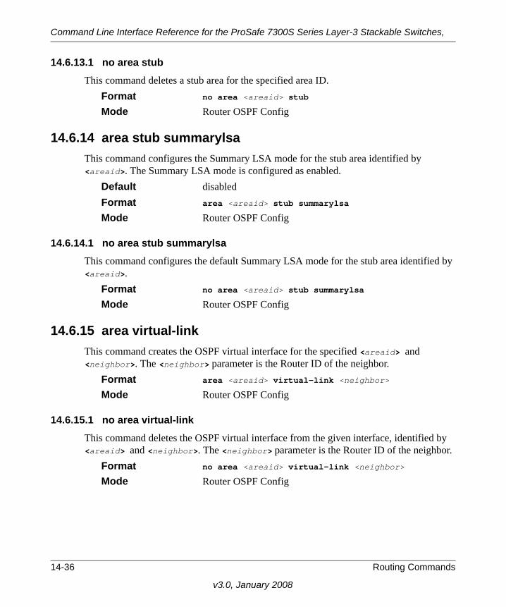
Command Line Interface Reference for the ProSafe 7300S Series Layer-3 Stackable Switches,
14.6.13.1 no area stub This command deletes a stub area for the specified area ID.
Format no area <areaid> stub
Mode Router OSPF Config
14.6.14 area stub summarylsaThis command configures the Summary LSA mode for the stub area identified by <areaid>. The Summary LSA mode is configured as enabled.
Default disabledFormat area <areaid> stub summarylsa
Mode Router OSPF Config
14.6.14.1 no area stub summarylsaThis command configures the default Summary LSA mode for the stub area identified by <areaid>.
Format no area <areaid> stub summarylsa
Mode Router OSPF Config
14.6.15 area virtual-link This command creates the OSPF virtual interface for the specified <areaid> and <neighbor>. The <neighbor> parameter is the Router ID of the neighbor.
Format area <areaid> virtual-link <neighbor>
Mode Router OSPF Config
14.6.15.1 no area virtual-link This command deletes the OSPF virtual interface from the given interface, identified by <areaid> and <neighbor>. The <neighbor> parameter is the Router ID of the neighbor.
Format no area <areaid> virtual-link <neighbor>
Mode Router OSPF Config
14-36 Routing Commands
v3.0, January 2008

Command Line Interface Reference for the ProSafe 7300S Series Layer-3 Stackable Switches,
14.6.16 area virtual-link authenticationThis command configures the authentication type and key for the OSPF virtual interface identified by <areaid> and <neighbor>. The <neighbor> parameter is the Router ID of the neighbor. The value for <type> is either none, simple, or encrypt. The [key] is composed of standard displayable, non-control keystrokes from a Standard 101/102-key keyboard. The authentication key must be 8 bytes or less if the authentication type is simple.
If the type is encrypt, the key may be up to 256 bytes. Unauthenticated interfaces do not need an authentication key. If the type is encrypt, a key id in the range of 0 and 255 must be specified.The default value for authentication type is none. Neither the default password key nor the default key id are configured.
Default none Format area <areaid> virtual-link <neighbor> authentica-
tion {none | {simple <key>} | {encrypt <key> <keyid>}}
Mode Router OSPF Config
14.6.16.1 no area virtual-link authenticationThis command configures the default authentication type for the OSPF virtual interface identified by <areaid> and <neighbor>. The <neighbor> parameter is the Router ID of the neighbor.
Format no area <areaid> virtual-link <neighbor> authenti-cation
Mode Router OSPF Config
14.6.17 area virtual-link dead-intervalThis command configures the dead interval for the OSPF virtual interface on the virtual interface identified by <areaid> and <neighbor>. The <neighbor> parameter is the Router ID of the neighbor. The range for <seconds> is 1 to 65535.
Default 40Format area <areaid> virtual-link <neighbor> dead-inter-
val <1-65535>
Mode Router OSPF Config
Routing Commands 14-37
v3.0, January 2008

Command Line Interface Reference for the ProSafe 7300S Series Layer-3 Stackable Switches,
14.6.17.1 no area virtual-link dead-intervalThis command configures the default dead interval for the OSPF virtual interface on the virtual interface identified by <areaid> and <neighbor>. The <neighbor> parameter is the Router ID of the neighbor.
Format no area <areaid> virtual-link <neighbor> dead-interval
Mode Router OSPF Config
14.6.18 area virtual-link hello-intervalThis command configures the hello interval for the OSPF virtual interface on the virtual interface identified by <areaid> and <neighbor>. The <neighbor> parameter is the Router ID of the neighbor. The range for <seconds> is 1 to 65535.
Default 10Format area <areaid> virtual-link <neighbor> hello-inter-
val <1-65535>
Mode Router OSPF Config
14.6.18.1 no area virtual-link hello-intervalThis command configures the default hello interval for the OSPF virtual interface on the virtual interface identified by <areaid> and <neighbor>. The <neighbor> parameter is the Router ID of the neighbor.
Format no area <areaid> virtual-link <neighbor> hello-interval
Mode Router OSPF Config
14.6.19 area virtual-link retransmit-intervalThis command configures the retransmit interval for the OSPF virtual interface on the virtual interface identified by <areaid> and <neighbor>. The <neighbor> parameter is the Router ID of the neighbor. The range for <seconds> is 0 to 3600.
Default 5Format area <areaid> virtual-link <neighbor> retransmit-
interval <0-3600>
Mode Router OSPF Config
14-38 Routing Commands
v3.0, January 2008

Command Line Interface Reference for the ProSafe 7300S Series Layer-3 Stackable Switches,
14.6.19.1 no area virtual-link retransmit-intervalThis command configures the default retransmit interval for the OSPF virtual interface on the virtual interface identified by <areaid> and <neighbor>. The <neighbor> parameter is the Router ID of the neighbor.
Format no area <areaid> virtual-link <neighbor> retrans-mit-interval
Mode Router OSPF Config
14.6.20 area virtual-link transmit-delayThis command configures the transmit delay for the OSPF virtual interface on the virtual interface identified by <areaid> and <neighbor>. The <neighbor> parameter is the Router ID of the neighbor. The range for <seconds> is 0 to 3600 (1 hour).
Default 1Format area <areaid> virtual-link <neighbor> transmit-
delay <0-3600>
Mode Router OSPF Config
14.6.20.1 no area virtual-link transmit-delayThis command configures the default transmit delay for the OSPF virtual interface on the virtual interface identified by <areaid> and <neighbor>. The <neighbor> parameter is the Router ID of the neighbor.
Format no area <areaid> virtual-link <neighbor> transmit-delay
Mode Router OSPF Config
14.6.21 default-information originate (OSPF)This command is used to control the advertisement of default routes.
Default metric - unspecified; type - 2Format default-information originate [always] [metric <0-
16777215>] [metric-type {1 | 2}]
Mode Router OSPF Config
Routing Commands 14-39
v3.0, January 2008

Command Line Interface Reference for the ProSafe 7300S Series Layer-3 Stackable Switches,
14.6.21.1 no default-information originate (OSPF)This command is used to control the advertisement of default routes.
Format no default-information originate [metric] [metric-type]
Mode Router OSPF Config
14.6.22 default-metric (OSPF)This command is used to set a default for the metric of distributed routes.
Format default-metric <1-16777215>
Mode Router OSPF Config
14.6.22.1 no default-metric (OSPF)This command is used to set a default for the metric of distributed routes.
Format no default-metric
Mode Router OSPF Config
14.6.23 distance ospf This command sets the route preference value of OSPF in the router. Lower route preference values are preferred when determining the best route. The type of OSPF can be intra, inter, type-1, or type-2. The OSPF specification (RFC 2328) requires that preferences must be given to the routes learned via OSPF in the following order: intra < inter < type-1 < type-2. The <preference> range is 1 to 255.
Default intra - 8; inter - 10; type-1, 13; type-2, 50.Format distance ospf {intra | inter | type1 | type2}
<preference>
Mode Router OSPF Config
14.6.23.1 no distance ospf This command sets the default route preference value of OSPF in the router.
Format no distance ospf {intra | inter | type1 | type2}
Mode Router OSPF Config
14-40 Routing Commands
v3.0, January 2008
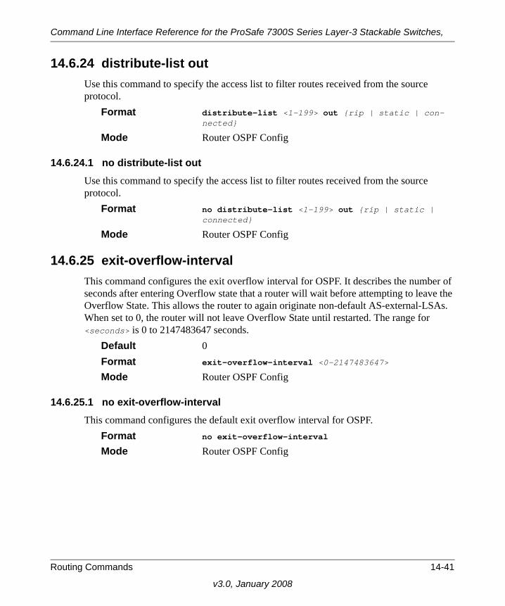
Command Line Interface Reference for the ProSafe 7300S Series Layer-3 Stackable Switches,
14.6.24 distribute-list outUse this command to specify the access list to filter routes received from the source protocol.
Format distribute-list <1-199> out {rip | static | con-nected}
Mode Router OSPF Config
14.6.24.1 no distribute-list outUse this command to specify the access list to filter routes received from the source protocol.
Format no distribute-list <1-199> out {rip | static | connected}
Mode Router OSPF Config
14.6.25 exit-overflow-interval This command configures the exit overflow interval for OSPF. It describes the number of seconds after entering Overflow state that a router will wait before attempting to leave the Overflow State. This allows the router to again originate non-default AS-external-LSAs. When set to 0, the router will not leave Overflow State until restarted. The range for <seconds> is 0 to 2147483647 seconds.
Default 0Format exit-overflow-interval <0-2147483647>
Mode Router OSPF Config
14.6.25.1 no exit-overflow-interval This command configures the default exit overflow interval for OSPF.
Format no exit-overflow-interval
Mode Router OSPF Config
Routing Commands 14-41
v3.0, January 2008

Command Line Interface Reference for the ProSafe 7300S Series Layer-3 Stackable Switches,
14.6.26 external-lsdb-limit This command configures the external LSDB limit for OSPF. If the value is -1, then there is no limit. When the number of non-default AS-external-LSAs in a router's link-state database reaches the external LSDB limit, the router enters overflow state. The router never holds more than the external LSDB limit non-default AS-external-LSAs in it database. The external LSDB limit MUST be set identically in all routers attached to the OSPF backbone and/or any regular OSPF area. The range for <limit> is -1 to 2147483647.
Default -1Format external-lsdb-limit <-1-2147483647>
Mode Router OSPF Config
14.6.26.1 no external-lsdb-limit This command configures the default external LSDB limit for OSPF.
Format no external-lsdb-limit
Mode Router OSPF Config
14.6.27 ip ospf areaid This command sets the OSPF area to which the specified router interface belongs. The value for <areaid> is an IP address, formatted as a 4-digit dotted-decimal number that uniquely identifies the area to which the interface connects. Assigning an area id, which does not exist on an interface, causes the area to be created with default values.
Format ip ospf areaid <areaid>
Mode Interface Config
14.6.28 ip ospf authentication This command sets the OSPF Authentication Type and Key for the specified interface. The value of <type> is either none, simple or encrypt. The [key] is composed of standard displayable, non-control keystrokes from a Standard 101/102-key keyboard. The authentication key must be 8 bytes or less if the authentication type is simple. If the type is encrypt, the key may be up to 256 bytes. If the type is encrypt a <keyid> in the range of 0 and 255 must be specified. Unauthenticated interfaces do not need an authentication key or authentication key ID.
Default none
14-42 Routing Commands
v3.0, January 2008

Command Line Interface Reference for the ProSafe 7300S Series Layer-3 Stackable Switches,
Format ip ospf authentication {none | {simple <key>} | {encrypt <key> <keyid>}}
Mode Interface Config
14.6.28.1 no ip ospf authentication This command sets the default OSPF Authentication Type for the specified interface.
Format no ip ospf authentication
Mode Interface Config
14.6.29 ip ospf cost This command configures the cost on an OSPF interface. The <cost> parameter has a range of 1 to 65535.
Default 10Format ip ospf cost <1-65535>
Mode Interface Config
14.6.29.1 no ip ospf cost This command configures the default cost on an OSPF interface.
Format no ip ospf cost
Mode Interface Config
14.6.30 ip ospf dead-intervalThis command sets the OSPF dead interval for the specified interface. The interval is the length of time in seconds that a router's Hello packets have not been seen before its neighbor routers declare that the router is down. The interval must be the same for all routers attached to a common network. This value should be some multiple of the Hello Interval (i.e. 4).
Default 40 Format ip ospf dead-interval <1-2147483647>
Mode Interface Config
Routing Commands 14-43
v3.0, January 2008

Command Line Interface Reference for the ProSafe 7300S Series Layer-3 Stackable Switches,
14.6.30.1 no ip ospf dead-intervalThis command sets the default OSPF dead interval for the specified interface.
Format no ip ospf dead-interval
Mode Interface Config
14.6.31 ip ospf hello-interval This command sets the OSPF hello interval for the specified interface. The interval is the length of time in seconds. The value for the length of time must be the same for all routers attached to a network. Valid values range from 1 to 65535.
Default 10Format ip ospf hello-interval <1-65535>
Mode Interface Config
14.6.31.1 no ip ospf hello-interval This command sets the default OSPF hello interval for the specified interface.
Format no ip ospf hello-interval
Mode Interface Config
14.6.32 ip ospf priority This command sets the OSPF priority for the specified router interface. The priority of the interface is a priority integer from 0 to 255. A value of 0 indicates that the router is not eligible to become the designated router on this network.
Default 1, which is the highest router priority. Format ip ospf priority <0-255>
Mode Interface Config
14.6.32.1 no ip ospf priority This command sets the default OSPF priority for the specified router interface.
Format no ip ospf priority
Mode Interface Config
14-44 Routing Commands
v3.0, January 2008

Command Line Interface Reference for the ProSafe 7300S Series Layer-3 Stackable Switches,
14.6.33 ip ospf retransmit-interval This command sets the OSPF retransmit Interval for the specified interface. The retransmit interval is specified in seconds. The value for <seconds> is the number of seconds between link-state advertisement retransmissions for adjacencies belonging to this router interface. This value is also used when retransmitting database description and link-state request packets. Valid values range from 0 to 3600 (1 hour).
Default 5Format ip ospf retransmit-interval <0-3600>
Mode Interface Config
14.6.33.1 no ip ospf retransmit-interval This command sets the default OSPF retransmit Interval for the specified interface.
Format no ip ospf retransmit-interval
Mode Interface Config
14.6.34 ip ospf transmit-delay This command sets the OSPF Transit Delay for the specified interface. The transmit delay is specified in seconds. In addition, it sets the estimated number of seconds it takes to transmit a link state update packet over this interface. Valid values for <seconds> range from 1 to 3600 (1 hour).
Default 1Format ip ospf transmit-delay <1-3600>
Mode Interface Config
14.6.34.1 no ip ospf transmit-delay This command sets the default OSPF Transit Delay for the specified interface.
Format no ip ospf transmit-delay
Mode Interface Config
Routing Commands 14-45
v3.0, January 2008

Command Line Interface Reference for the ProSafe 7300S Series Layer-3 Stackable Switches,
14.6.35 ip ospf mtu-ignoreThis command disables OSPF maximum transmission unit (MTU) mismatch detection. OSPF Database Description packets specify the size of the largest IP packet that can be sent without fragmentation on the interface. When a router receives a Database Description packet, it examines the MTU advertised by the neighbor. By default, if the MTU is larger than the router can accept, the Database Description packet is rejected and the OSPF adjacency is not established.
Default enabledFormat ip ospf mtu-ignore
Mode Interface Config
14.6.35.1 no ip ospf mtu-ignoreThis command enables the OSPF MTU mismatch detection.
Format no ip ospf mtu-ignore
Mode Interface Config
14.6.36 router-id This command sets a 4-digit dotted-decimal number uniquely identifying the router ospf id. The <ipaddress> is a configured value.
Format router-id <ipaddress>
Mode Router OSPF Config
14.6.37 redistribute This command configures OSPF protocol to allow redistribution of routes from the specified source protocol/routers.
Default metric - unspecified; type - 2; tag - 0Format redistribute {rip | static | connected} [metric
<0-16777215>] [metric-type {1 | 2}] [tag <0-4294967295>] [subnets]
Mode Router OSPF Config
14-46 Routing Commands
v3.0, January 2008

Command Line Interface Reference for the ProSafe 7300S Series Layer-3 Stackable Switches,
14.6.37.1 no redistribute This command configures OSPF protocol to prohibit redistribution of routes from the specified source protocol/routers.
Format no redistribute {rip | static | connected} [met-ric] [metric-type] [tag] [subnets]
Mode Router OSPF Config
14.6.38 maximum-pathsThis command sets the number of paths that OSPF can report for a given destination where maxpaths is platform dependent.
Default 4Format maximum-paths <maxpaths>
Mode Router OSPF Config
14.6.38.1 no maximum-pathsThis command resets the number of paths that OSPF can report for a given destination back to its default value.
Format no maximum-paths
Mode Router OSPF Config
14.6.39 trapflags This command enables OSPF traps.
Default enabledFormat trapflags
Mode Router OSPF Config
14.6.39.1 no trapflags This command disables OSPF traps.
Format no trapflags
Mode Router OSPF Config
Routing Commands 14-47
v3.0, January 2008

Command Line Interface Reference for the ProSafe 7300S Series Layer-3 Stackable Switches,
14.6.40 show ip ospf This command displays information relevant to the OSPF router.
Format show ip ospf
Mode Privileged EXEC
Router ID Is a 32 bit integer in dotted decimal format identifying the router, about which information is displayed. This is a config-ured value.
OSPF Admin Mode Shows whether the administrative mode of OSPF in the
router is enabled or disabled. This is a configured value. ASBR Mode Reflects whether the ASBR mode is enabled or disabled.
Enable implies that the router is an autonomous system bor-der router. Router automatically becomes an ASBR when it is configured to redistribute routes learnt from other protocol. The possible values for the ASBR status is enabled (if the router is configured to re-distribute routes learnt by other pro-tocols) or disabled (if the router is not configured for the same).
RFC 1583 Compatibility Reflects whether 1583 compatibility is enabled or disabled.
This is a configured value.ABR Status Shows whether the router is an OSPF Area Border Router.Exit Overflow Interval Shows the number of seconds that, after entering Overflow-
State, a router will attempt to leave OverflowState.External LSA Count Shows the number of external (LS type 5) link-state adver-
tisements in the link-state database. External LSA Checksum Shows the sum of the LS checksums of external link-state
advertisements contained in the link-state database.
Note: Some of the information below displays only if you enable OSPF and configure certain features.
14-48 Routing Commands
v3.0, January 2008

Command Line Interface Reference for the ProSafe 7300S Series Layer-3 Stackable Switches,
New LSAs Originated Shows the number of new link-state advertisements that have
been originated.LSAs Received Shows the number of link-state advertisements received
determined to be new instantiations. External LSDB Limit Shows the maximum number of non-default AS-external-
LSAs entries that can be stored in the link-state database.Default Metric Default value for redistributed routes.Default Route Advertise Indicates whether the default routes received from other
source protocols are advertised or notAlways Shows whether default routes are always advertised.Metric Shows the metric for the advertised default routes. If the met-
ric is not configured, this field is blank.Metric Type Shows whether the routes are External Type 1 or External
Type 2.Maximum Paths Shows the maximum number of paths that OSPF can report
for a given destination.Redistributing This field is a heading and appears only if you configure the
system to take routes learned from a non-OSPF source and advertise them to its peers.
Source Shows source protocol/routes that are being redistributed. Possible values are static, connected, or RIP.
Metric Shows the metric of the routes being redistributed.Metric Type Shows whether the routes are External Type 1 or External
Type 2.Tag Shows the decimal value attached to each external route. Subnets For redistributing routes into OSPF, the scope of redistribu-
tion for the specified protocol.Distribute-List Shows the access list used to filter redistributed routes.
Routing Commands 14-49
v3.0, January 2008

Command Line Interface Reference for the ProSafe 7300S Series Layer-3 Stackable Switches,
14.6.41 show ip ospf area This command displays information about the area. The <areaid> identifies the OSPF area that is being displayed.
Format show ip ospf area <areaid>
Modes Privileged EXECUser EXEC
AreaID Is the area id of the requested OSPF area.Aging Interval Is a number representing the aging interval for this area.External Routing Is a number representing the external routing capabilities for
this area.Authentication Type Is the configured authentication type to use for this area.Spf Runs Is the number of times that the intra-area route table has been
calculated using this area's link-state database.Area Border Router Count The total number of area border routers reachable within this
area.Area LSA Count Total number of link-state advertisements in this area's link-
state database, excluding AS External LSAs.Area LSA Checksum A number representing the Area LSA Checksum for the spec-
ified AreaID excluding the external (LS type 5) link-state advertisements.
Stub Mode Represents whether the specified Area is a stub area or not. The possible values are enabled and disabled. This is a con-figured value.
Import Summary LSAs Controls the import of summary LSAs into stub areas. The
possible values are enabled or disabled.Metric Value Is a number representing the Metric Value for the specified
area. Metric Type Is the Default Metric Type for the specified Area. If the area
is a stub area, this field does not appear.
14-50 Routing Commands
v3.0, January 2008

Command Line Interface Reference for the ProSafe 7300S Series Layer-3 Stackable Switches,
14.6.42 show ip ospf database This command displays the link state database. The OSPF database information is grouped into sections by link-type and area. The groups are as follows:
• Router Link States
• Network Link States
• Network Summary States
• Summary ASBR States
The AS-Externals are not grouped by area.Format show ip ospf database
Modes Privileged EXECUser EXEC
Link Id Is a number that uniquely identifies an LSA that a router orig-inates from all other self originated LSAs of the same LS type.
Adv Router The Advertising Router. Is a 32 bit dotted decimal number representing the LSDB interface.
Age Is a number representing the age of the link state advertise-ment in seconds.
Sequence Is a number that represents which LSA is more recent.Checksum Is the total number LSA checksum. Options This is an integer. It indicates that the LSA receives special
handling during routing calculations.Rtr Opt Router Options are valid for router links only.
14.6.43 show ip ospf interfaceThis command displays brief information for the IFO object or virtual interface tables.
Format show ip ospf interface
Note: The information below is only displayed if OSPF is enabled.
Routing Commands 14-51
v3.0, January 2008

Command Line Interface Reference for the ProSafe 7300S Series Layer-3 Stackable Switches,
Modes Privileged EXECUser EXEC
Interface Valid slot and port number separated by forward slashes.OSPF Admin Mode States whether OSPF is enabled or disabled on a router inter-
face. OSPF Area ID Represents the OSPF Area Id for the specified interface. Router Priority A number representing the OSPF Priority for the specified
interface.Hello Interval A number representing the OSPF Hello Interval for the speci-
fied interface. Dead Interval A number representing the OSPF Dead Interval for the speci-
fied interface. Retransmit Interval A number representing the OSPF Retransmit Interval for the
specified interface. Transit Delay Interval A number representing the OSPF Transit Delay for the speci-
fied interface. LSA Ack Interval A number representing the OSPF LSA Acknowledgement
Interval for the specified interface.
14.6.44 show ip ospf interface <unit/slot/port>This command displays the information for the IFO object or virtual interface tables.
Format show ip ospf interface <unit/slot/port>
Modes Privileged EXECUser EXEC
IP Address Represents the IP address for the specified interface.Subnet Mask A mask of the network and host portion of the IP address for
the OSPF interface. OSPF Admin Mode States whether OSPF is enabled or disabled on a router inter-
face. OSPF Area ID Represents the OSPF Area Id for the specified interface.
14-52 Routing Commands
v3.0, January 2008

Command Line Interface Reference for the ProSafe 7300S Series Layer-3 Stackable Switches,
Router Priority A number representing the OSPF Priority for the specified interface.
Retransmit Interval A number representing the OSPF Retransmit Interval for the
specified interface. Hello Interval A number representing the OSPF Hello Interval for the speci-
fied interface. Dead Interval A number representing the OSPF Dead Interval for the speci-
fied interface.LSA Ack Interval A number representing the OSPF LSA Acknowledgement
Interval for the specified interface. Transit Delay Interval A number representing the OSPF Transit Delay for the speci-
fied interface. Authentication Type The OSPF Authentication Type for the specified interface
are: none, simple, and encrypt.
The information below will only be displayed if OSPF is enabled.OSPF Interface Type Broadcast LANs, such as Ethernet and IEEE 802.5, take the
value broadcast. The OSPF Interface Type will be 'broadcast'. State The OSPF Interface States are: down, loopback, waiting,
point-to-point, designated router, and backup designated router.
Designated Router The router ID representing the designated router. Backup Designated Router The router ID representing the backup designated router. Number of Link Events The number of link events. Metric Cost The cost of the OSPF interface.
Routing Commands 14-53
v3.0, January 2008

Command Line Interface Reference for the ProSafe 7300S Series Layer-3 Stackable Switches,
14.6.45 show ip ospf interface stats This command displays the statistics for a specific interface. The information below will only be displayed if OSPF is enabled.
Format show ip ospf interface stats <unit/slot/port>
Modes Privileged EXECUser EXEC
OSPF Area ID The area id of this OSPF interface.Spf Runs The number of times that the intra-area route table has been
calculated using this area's link-state database. Area Border Router Count The total number of area border routers reachable within this
area. This is initially zero, and is calculated in each SPF pass. AS Border Router Count The total number of Autonomous System border routers
reachable within this area.Area LSA Count The total number of link-state advertisements in this area's
link-state database, excluding AS External LSAs. IP Address The IP address associated with this OSPF interface.OSPF Interface Events The number of times the specified OSPF interface has
changed its state, or an error has occurred. Virtual Events The number of state changes or errors that occurred on this
virtual link. Neighbor Events The number of times this neighbor relationship has changed
state, or an error has occurred. External LSA Count The number of external (LS type 5) link-state advertisements
in the link-state database. LSAs Received The number of LSAs received.Originate New LSAs The number of LSAs originated.
14-54 Routing Commands
v3.0, January 2008

Command Line Interface Reference for the ProSafe 7300S Series Layer-3 Stackable Switches,
14.6.46 show ip ospf neighborThis command displays the OSPF neighbor table list. The information below is displayed only if OSPF is enabled.
Format show ip ospf neighbor {<unit/slot/port> | all}
Modes Privileged EXECUser EXEC
Router ID A 4 digit dotted decimal number representing the neighbor interface.
IP Address An IP address representing the neighbor interface.Neighbor Interface Index Is a unit/slot/port identifying the neighbor interface
index.State Displays the current state of the neighboring router. Possible
values are: Down- initial state of the neighbor conversation - no recent
information has been received from the neighbor. Attempt - no recent information has been received from the
neighbor but a more concerted effort should be made to con-tact the neighbor.
Init - an Hello packet has recently been seen from the neigh-bor, but bi-directional communication has not yet been estab-lished.
2 way - communication between the two routers is bi-direc-tional.
Exchange start - the first step in creating an adjacency between the two neighboring routers, the goal is to decide which router is the master and to decide upon the initial DD sequence number.
Exchange - the router is describing its entire link state data-base by sending Database Description packets to the neigh-bor.
Loading - Link State Request packets are sent to the neighbor asking for the more recent LSAs that have been discovered (but not yet received) in the Exchange state.
Routing Commands 14-55
v3.0, January 2008

Command Line Interface Reference for the ProSafe 7300S Series Layer-3 Stackable Switches,
Full - the neighboring routers are fully adjacent and they will now appear in router-LSAs and network-LSAs.
14.6.47 show ip ospf neighbor <ipaddr>This command displays the OSPF neighbor table list. When you specify a particular neighbor ID, detailed information about a neighbor is given. The information below displays only if OSPF is enabled and the interface has a neighbor. The <ipaddr> parameter is the IP address of the neighbor.
Format show ip ospf neighbor <ipaddr> <unit/slot/port>
Modes Privileged EXECUser EXEC
Interface Valid slot and port number separated by forward slashes..Router Id Is a 4-digit dotted-decimal number identifying neighbor
router.Options Indicates the optional OSPF capabilities supported by the
neighbor. The neighbor's optional OSPF capabilities are also listed in its Hello packets. This enables received Hello Pack-ets to be rejected (neighbor relationships will not even start to form) if there is a mismatch in certain crucial OSPF capabili-ties.
Router Priority Displays the OSPF priority for the specified interface. The priority of an interface is a priority integer from 0 to 255. A value of '0' indicates that the router is not eligible to become the designated router on this network.
State Shows the state of the neighboring routers. Possible values are:
Down- initial state of the neighbor conversation - no recent information has been received from the neighbor.
Attempt - no recent information has been received from the neighbor but a more concerted effort should be made to con-tact the neighbor.
Init - an Hello packet has recently been seen from the neigh-bor, but bi-directional communication has not yet been estab-lished.
2 way - communication between the two routers is bi-direc-tional.
14-56 Routing Commands
v3.0, January 2008

Command Line Interface Reference for the ProSafe 7300S Series Layer-3 Stackable Switches,
Exchange start - the first step in creating an adjacency between the two neighboring routers, the goal is to decide which router is the master and to decide upon the initial DD sequence number.
Exchange - the router is describing its entire link state data-base by sending Database Description packets to the neigh-bor.
Loading - Link State Request packets are sent to the neighbor asking for the more recent LSAs that have been discovered (but not yet received) in the Exchange state.
Full - the neighboring routers are fully adjacent and they will now appear in router-LSAs and network-LSAs.
Events The number of times this neighbor relationship has changed state, or an error has occurred.
Permanence Displays the status of the entry, either dynamic or permanent. This refers to how the neighbor became known.
Hellos Suppressed Indicates whether Hellos are being suppressed to the neigh-
bor.Retransmission Queue Length Is an integer representing the current length of the retransmis-
sion queue of the specified neighbor router Id of the specified interface.
14.6.48 show ip ospf rangeThis command displays information about the area ranges for the specified <areaid>. The <areaid> identifies the OSPF area whose ranges are being displayed.
Format show ip ospf range <areaid>
Modes Privileged EXECUser EXEC
Area ID The area id of the requested OSPF area.IP Address An IP Address which represents this area range.Subnet Mask A valid subnet mask for this area range.Lsdb Type The type of link advertisement associated with this area
range.
Routing Commands 14-57
v3.0, January 2008

Command Line Interface Reference for the ProSafe 7300S Series Layer-3 Stackable Switches,
Advertisement The status of the advertisement.Possible values are enabled or disabled.
14.6.49 show ip ospf stub tableThis command displays the OSPF stub table. The information below will only be displayed if OSPF is initialized on the switch.
Format show ip ospf stub table
Modes Privileged EXECUser EXEC
Area ID Is a 32-bit identifier for the created stub area.Type of Service Is the type of service associated with the stub metric. The
7300S Series Stackable Switch only supports Normal TOS.Metric Val The metric value is applied based on the TOS. It defaults to
the least metric of the type of service among the interfaces to other areas. The OSPF cost for a route is a function of the metric value.
Metric Type Is the type of metric advertised as the default route.Import Summary LSA Controls the import of summary LSAs into stub areas.
14.6.50 show ip ospf virtual-linkThis command displays the OSPF Virtual Interface information for all areas in the system.
Format show ip ospf virtual-link
Modes Privileged EXECUser EXEC
Area Id The area id of the requested OSPF area.Neighbor The neighbor interface of the OSPF virtual interface.Hello Interval The configured hello interval for the OSPF virtual interface.Dead Interval The configured dead interval for the OSPF virtual interface.Retransmit Interval The configured retransmit interval for the OSPF virtual inter-
face.Transit Delay The configured transit delay for the OSPF virtual interface.
14-58 Routing Commands
v3.0, January 2008

Command Line Interface Reference for the ProSafe 7300S Series Layer-3 Stackable Switches,
14.6.51 show ip ospf virtual-link <area_id>This command displays the OSPF Virtual Interface information for a specific area and neighbor. The <areaid> parameter identifies the area and the <neighbor> parameter identifies the neighbor's Router ID.
Format show ip ospf virtual-link <areaid> <neighbor>
Modes Privileged EXECUser EXEC
Area ID The area id of the requested OSPF area.Neighbor Router ID The input neighbor Router ID.Hello Interval The configured hello interval for the OSPF virtual interface.Dead Interval The configured dead interval for the OSPF virtual interface.Iftransit Delay Interval The configured transit delay for the OSPF virtual interface.Retransmit Interval The configured retransmit interval for the OSPF virtual inter-
face.Authentication Type The configured authentication type of the OSPF virtual inter-
face.State The OSPF Interface States are: down, loopback, waiting,
point-to-point, designated router, and backup designated router. This is the state of the OSPF interface.
Neighbor State The neighbor state.
Routing Commands 14-59
v3.0, January 2008

Command Line Interface Reference for the ProSafe 7300S Series Layer-3 Stackable Switches,
14.7 Routing Information Protocol (RIP) CommandsThis section describes the commands you use to view and configure RIP, which is a distance-vector routing protocol that you use to route traffic within a small network.
14.7.1 router ripUse this command to enter Router RIP mode.
Format router rip
Mode Global Config
14.7.2 enable (RIP)This command resets the default administrative mode of RIP in the router (active).
Default enabledFormat enable
Mode Router RIP Config
14.7.2.1 no enable (RIP)This command sets the administrative mode of RIP in the router to inactive.
Format no enable
Mode Router RIP Config
14.7.3 ip ripThis command enables RIP on a router interface.
Default disabledFormat ip rip
Mode Interface Config
14.7.3.1 no ip ripThis command disables RIP on a router interface.
Format no ip rip
Mode Interface Config
14-60 Routing Commands
v3.0, January 2008

Command Line Interface Reference for the ProSafe 7300S Series Layer-3 Stackable Switches,
14.7.4 auto-summaryThis command enables the RIP auto-summarization mode.
Default disabledFormat auto-summary
Mode Router RIP Config
14.7.4.1 no auto-summaryThis command disables the RIP auto-summarization mode.
Format no auto-summary
Mode Router RIP Config
14.7.5 default-information originate (RIP)This command is used to control the advertisement of default routes.
Format default-information originate
Mode Router RIP Config
14.7.5.1 no default-information originate (RIP)This command is used to control the advertisement of default routes.
Format no default-information originate
Mode Router RIP Config
14.7.6 default-metric (RIP)This command is used to set a default for the metric of distributed routes.
Format default-metric <0-15>
Mode Router RIP Config
14.7.6.1 no default-metric (RIP)This command is used to reset the default metric of distributed routes to its default value.
Format no default-metric
Mode Router RIP Config
Routing Commands 14-61
v3.0, January 2008

Command Line Interface Reference for the ProSafe 7300S Series Layer-3 Stackable Switches,
14.7.7 distance ripThis command sets the route preference value of RIP in the router. Lower route preference values are preferred when determining the best route.
Default 15Format distance rip <1-255>
Mode Router RIP Config
14.7.7.1 no distance ripThis command sets the default route preference value of RIP in the router.
Format no distance rip
Mode Router RIP Config
14.7.8 distribute-list outThis command is used to specify the access list to filter routes received from the source protocol.
Default 0Format distribute-list <1-199> out {ospf | static | con-
nected}
Mode Router RIP Config
14.7.8.1 no distribute-list outThis command is used to specify the access list to filter routes received from the source protocol.
Format no distribute-list <1-199> out {ospf | static | connected}
Mode Router RIP Config
14.7.8.2 no default-information originateThis command is used to control the advertisement of default routes.
Format no default-information originate
Mode Router RIP Config
14-62 Routing Commands
v3.0, January 2008

Command Line Interface Reference for the ProSafe 7300S Series Layer-3 Stackable Switches,
14.7.9 ip rip authentication This command sets the RIP Version 2 Authentication Type and Key for the specified interface. The value of <type> is either none, simple, or encrypt. The value for authentication key [key] must be 16 bytes or less. The [key] is composed of standard displayable, non-control keystrokes from a Standard 101/102-key keyboard. If the value of <type> is encrypt, a keyid in the range of 0 and 255 must be specified. Unauthenticated interfaces do not need an authentication key or authentication key ID.
Default noneFormat ip rip authentication {none | {simple <key>} |
{encrypt <key> <keyid>}}
Mode Interface Config
14.7.9.1 no ip rip authentication This command sets the default RIP Version 2 Authentication Type for an interface.
Format no ip rip authentication
Mode Interface Config
14.7.10 ip rip receive version This command configures the interface to allow RIP control packets of the specified version(s) to be received.
The value for <mode> is one of: rip1 to receive only RIP version 1 formatted packets, rip2 for RIP version 2, both to receive packets from either format, or none to not allow any RIP control packets to be received.
Default bothFormat ip rip receive version {rip1 | rip2 | both | none}
Mode Interface Config
14.7.10.1 no ip rip receive version This command configures the interface to allow RIP control packets of the default version(s) to be received.
Format no ip rip receive version
Mode Interface Config
Routing Commands 14-63
v3.0, January 2008

Command Line Interface Reference for the ProSafe 7300S Series Layer-3 Stackable Switches,
14.7.11 ip rip send version This command configures the interface to allow RIP control packets of the specified version to be sent.
The value for <mode> is one of: rip1 to broadcast RIP version 1 formatted packets, rip1c (RIP version 1 compatibility mode) which sends RIP version 2 formatted packets via broadcast, rip2 for sending RIP version 2 using multicast, or none to not allow any RIP control packets to be sent.
Default rip2Format ip rip send version {rip1 | rip1c | rip2 | none}
Mode Interface Config
14.7.11.1 no ip rip send version This command configures the interface to allow RIP control packets of the default version to be sent.
Format no ip rip send version
Mode Interface Config
14.7.12 hostroutesacceptThis command enables the RIP hostroutesaccept mode.
Default enabledFormat hostroutesaccept
Mode Router RIP Config
14.7.12.1 no hostroutesacceptThis command disables the RIP hostroutesaccept mode.
Format no hostroutesaccept
Mode Router RIP Config
14-64 Routing Commands
v3.0, January 2008

Command Line Interface Reference for the ProSafe 7300S Series Layer-3 Stackable Switches,
14.7.13 split-horizonThis command sets the RIP split horizon mode.
Default simpleFormat split-horizon {none | simple | poison}
Mode Router RIP Config
14.7.13.1 no split-horizonThis command sets the default RIP split horizon mode.
Format no split-horizon
Mode Router RIP Config
14.7.14 redistribute This command configures RIP protocol to redistribute routes from the specified source protocol/routers. There are five possible match options. When you submit the command redistribute ospf match <match-type> the match-type or types specified are added to any match types presently being redistributed. Internal routes are redistributed by default.
Default metric - not-configured; match - internalFormat for OSPF as source protocol
redistribute ospf [metric <0-15>] [match [inter-nal] [external 1] [external 2] [nssa-external 1] [nssa-external-2]]
Format for other source protocol
redistribute {static | connected} [metric <0-15>]
Mode Router RIP Config
14.7.14.1 no redistribute This command de-configures RIP protocol to redistribute routes from the specified source protocol/routers.
Format no redistribute {ospf | static | connected} [met-ric] [match [internal] [external 1] [external 2] [nssa-external 1] [nssa-external-2]]
Mode Router RIP Config
Routing Commands 14-65
v3.0, January 2008

Command Line Interface Reference for the ProSafe 7300S Series Layer-3 Stackable Switches,
14.7.15 show ip rip This command displays information relevant to the RIP router.
Format show ip ripModes Privileged EXEC
User EXECRIP Admin Mode Enable or disable. Split Horizon Mode None, simple or poison reverse. Split horizon is a technique
for avoiding problems caused by including routes in updates sent to the router from which the route was originally learned. The options are: None - no special processing for this case. Simple - a route will not be included in updates sent to the router from which it was learned. Poisoned reverse - a route will be included in updates sent to the router from which it was learned, but the metric will be set to infinity. The default is simple
Auto Summary Mode Enable or disable. If enabled, groups of adjacent routes are
summarized into single entries, in order to reduce the total number of entries The default is enable.
Host Routes Accept Mode Enable or disable. If enabled the router accepts host routes.
The default is enable. Global Route Changes The number of route changes made to the IP Route Database
by RIP. This does not include the refresh of a route's age. Global queries - The number of responses sent to RIP queries from other sys-
tems.Default Metric Sets a default for the metric of redistributed routes.This field
displays the default metric if one has already been set or blank if not configured earlier. The valid values are (1 to 15)
Default Route Advertise The default route.
14-66 Routing Commands
v3.0, January 2008

Command Line Interface Reference for the ProSafe 7300S Series Layer-3 Stackable Switches,
14.7.16 show ip rip interfaceThis command displays general information for each RIP interface. For this command to display successful results routing must be enabled per interface (i.e. ip rip).
Format show ip rip interface
Modes Privileged EXEC User EXEC
Interface Valid slot and port number separated by forward slashes.IP Address The IP source address used by the specified RIP interface.Send Version The RIP version(s) used when sending updates on the speci-
fied interface. The types are none, RIP-1, RIP-1c, RIP-2.Receive Version The RIP version(s) allowed when receiving updates from the
specified interface. The types are none, RIP-1, RIP-2, Both RIP Mode RIP administrative mode of router RIP operation; enable acti-
vates, disable de-activates it.Link State The mode of the interface (up or down).
14.7.17 show ip rip interface <unit/slot/port>This command displays information related to a particular RIP interface.
Format show ip rip interface <unit/slot/port>
Modes Privileged EXEC User EXEC
Interface Valid slot and port number separated by forward slashes. This is a configured value.
IP Address The IP source address used by the specified RIP interface. This is a configured value.
Send version The RIP version(s) used when sending updates on the speci-fied interface. The types are none, RIP-1, RIP-1c, RIP-2. This is a configured value.
Receive version The RIP version(s) allowed when receiving updates from the specified interface. The types are none, RIP-1, RIP-2, Both. This is a configured value.
Both RIP Admin Mode RIP administrative mode of router RIP operation; enable acti-
vates, disable de-activates it. This is a configured value.
Routing Commands 14-67
v3.0, January 2008

Command Line Interface Reference for the ProSafe 7300S Series Layer-3 Stackable Switches,
Link State Indicates whether the RIP interface is up or down. This is a configured value.
Authentication Type The RIP Authentication Type for the specified interface. The
types are none, simple, and encrypt. This is a configured value.
Default Metric A number which represents the metric used for default routes in RIP updates originated on the specified interface. This is a configured value.
The following information will be invalid if the link state is down.Bad Packets Received The number of RIP response packets received by the RIP
process which were subsequently discarded for any reason.Bad Routes Received The number of routes contained in valid RIP packets that
were ignored for any reason.Updates Sent The number of triggered RIP updates actually sent on this
interface.
14-68 Routing Commands
v3.0, January 2008

Chapter 15IGMP Snooping Commands
This section describes the Internet Group Management Protocol (IGMP) snooping commands available in the 7300S Series Stackable Switch CLI.
The 7300S Series Stackable Switch supports IGMP Versions 1, 2, and 3. The IGMP snooping feature can help conserve bandwidth because it allows the switch to forward IP multicast traffic only to connected hosts that request multicast traffic. IGMPv3 adds source filtering capabilities to IGMP versions 1 and 2.
This section contains the following topics:
• Section 15.1 “IGMP Snooping Configuration Commands” on page 15-1
• Section 15.2 “IGMP Snooping Show Commands” on page 15-6
• Section 15.3 “IGMP Querier Commands” on page 15-9
The commands in this section are in one of two groups:
• Show commands are used to display switch settings, statistics and other information.
• Configuration Commands are used to configure features and options of the switch. For every configuration command there is a show command that will display the configuration setting.
15.1 IGMP Snooping Configuration CommandsThis section describes the commands you use to configure IGMP snooping.
15.1.1 ip igmpsnoopingThis command enables IGMP Snooping on the system (Global Config Mode) or an interface (Interface Config Mode). This command also enables IGMP snooping on a particular VLAN and can enable IGMP snooping on all interfaces participating in a VLAN.
IGMP Snooping Commands 15-1
v3.0, January 2008

Command Line Interface Reference for the ProSafe 7300S Series Layer-3 Stackable Switches,
If an interface has IGMP Snooping enabled and you enable this interface for routing or enlist it as a member of a port-channel (LAG), IGMP Snooping functionality is disabled on that interface. IGMP Snooping functionality is re-enabled if you disable routing or remove port-channel (LAG) membership from an interface that has IGMP Snooping enabled.
The IGMP application supports the following activities:
• Validation of the IP header checksum (as well as the IGMP header checksum) and discarding of the frame upon checksum error.
• Maintenance of the forwarding table entries based on the MAC address versus the IP address.
• Flooding of unregistered multicast data packets to all ports in the VLAN. Default disabledFormat ip igmpsnooping <vlanId>Modes Global Config
Interface ConfigVLAN Mode
15.1.1.1 no ip igmpsnoopingThis command disables IGMP Snooping on the system.
Format no ip igmpsnooping <vlanId>Modes Global Config
Interface ConfigVLAN Mode
15.1.2 ip igmpsnooping interfacemode This command enables IGMP Snooping on all interfaces. If an interface has IGMP Snooping enabled and you enable this interface for routing or enlist it as a member of a port-channel (LAG), IGMP Snooping functionality is disabled on that interface. IGMP Snooping functionality is re-enabled if you disable routing or remove port-channel (LAG) membership from an interface that has IGMP Snooping enabled.
Default disabledFormat ip igmpsnooping interfacemode
Mode Global Config
15-2 IGMP Snooping Commands
v3.0, January 2008

Command Line Interface Reference for the ProSafe 7300S Series Layer-3 Stackable Switches,
15.1.2.1 no ip igmpsnooping interfacemode This command disables IGMP Snooping on all interfaces.
Format no ip igmpsnooping interfacemode
Mode Global Config
15.1.3 ip igmpsnooping groupmembership-intervalThis command sets the IGMP Group Membership Interval time on a VLAN, one interface or all interfaces. The Group Membership Interval time is the amount of time in seconds that a switch waits for a report from a particular group on a particular interface before deleting the interface from the entry. This value must be greater than the IGMPv3 Maximum Response time value. The range is 2 to 3600 seconds.
Default 260 secondsFormat ip igmpsnooping groupmembership-interval <vlanId>
<2-3600>
Modes Interface ConfigGlobal ConfigVLAN Mode
15.1.3.1 no ip igmpsnooping groupmembership-intervalThis command sets the IGMPv3 Group Membership Interval time to the default value.
Format no ip igmpsnooping groupmembership-interval
Modes Interface ConfigGlobal ConfigVLAN Mode
IGMP Snooping Commands 15-3
v3.0, January 2008

Command Line Interface Reference for the ProSafe 7300S Series Layer-3 Stackable Switches,
15.1.4 ip igmpsnooping maxresponseThis command sets the IGMP Maximum Response time for the system, on a particular interface or VLAN. The Maximum Response time is the amount of time in seconds that a switch will wait after sending a query on an interface because it did not receive a report for a particular group in that interface. This value must be less than the IGMP Query Interval time value. The range is 1 to 3599 seconds.
Default 10 secondsFormat ip igmpsnooping maxresponse <1-3599>
Modes Global ConfigInterface ConfigVLAN Mode
15.1.4.1 no ip igmpsnooping maxresponseThis command sets the IGMP Maximum Response time (on the interface or VLAN) to the default value.
Format no ip igmpsnooping maxresponse
Modes Global ConfigInterface ConfigVLAN Mode
15.1.5 ip igmpsnooping mcrtexpiretimeThis command sets the Multicast Router Present Expiration time. The time is set for the system, on a particular interface or VLAN.
This is the amount of time in seconds that a switch waits for a query to be received on an interface before the interface is removed from the list of interfaces with multicast routers attached. The range is 0 to 3600 seconds. A value of 0 indicates an infinite time-out, i.e. no expiration.
Default 0 Format ip igmpsnooping mcrtexpiretime <vlanId> <0-3600>
Modes Global ConfigInterface Config
15-4 IGMP Snooping Commands
v3.0, January 2008

Command Line Interface Reference for the ProSafe 7300S Series Layer-3 Stackable Switches,
15.1.5.1 no ip igmpsnooping mcrtexpiretimeThis command sets the Multicast Router Present Expiration time to 0. The time is set for the system, on a particular interface or a VLAN.
Format no ip igmpsnooping mcrtexpiretime <vlanId> Modes Global Config
Interface Config
15.1.6 ip igmp mrouter This command configures the interface to only forward the snooped IGMP packets that come from VLAN ID (<vlanId>) to the multicast router mode attached to this interface. The command is not needed most of the time since the switch will automatically detect the presence of a multicast router and forward IGMP packets accordingly. It is only needed when you want to make sure that the multicast router always receives IGMP packets from the switch in a complex network.
Default Disabled Format ip igmp mrouter <vlanId>
Mode Interface Config
15.1.6.1 no ip igmp mrouter This command disables the forwarding of IGMP packets to this interface.
Format no ip igmp mrouter <vlanId>
Mode Interface Config
15.1.7 ip igmp mrouter interfaceThis command configures the interface as the one the multicast router is attached to. All IGMP packets snooped by the switch will be forwarded to the multicast router reachable from this interface. The command is not needed most of the time since the switch will automatically detect the presence of multicast router and forward IGMP packet accordingly. It is only needed when you want to make sure the multicast router always receives IGMP packets from the switch in a complex network.
Default DisabledFormat ip igmp mrouter interface
Mode Interface Config
IGMP Snooping Commands 15-5
v3.0, January 2008

Command Line Interface Reference for the ProSafe 7300S Series Layer-3 Stackable Switches,
15.1.7.1 no ip igmp mrouter interfaceThis command disables the forwarding of IGMP packets to a multicast router via this interface.
Format no ip igmp mrouter interface
Mode Interface Config
15.1.8 ip igmpsnooping unknown-multicast This command enables the filtering of unknown multicast packets to the VLAN. Packets with an unknown mulicast address in the destination field will be dropped. This command is mainly used when IGMP snooping is enabled, to prevent flooding of unwanted multicast packets to every port.
Format ip igmpsnooping unknown-multicast
Mode Global Config
15.1.8.1 no ip igmpsnooping unknown-mulitcastThis command disables the filtering of unknown multicast packets. Unknown multicast packets will be flooded to all ports in the same VLAN.
Format no ip igmpsnooping unknown-mulitcast
Mode Global Config
15.2 IGMP Snooping Show CommandsThis section describes the commands you use to view IGMP snooping status and information.
15.2.1 show ip igmpThis command displays IGMP Snooping information. Configured information is displayed whether or not IGMP Snooping is enabled.
Format show ip igmp [<unit/slot/port> | <vlanId>]
Mode Privileged EXEC
When the optional arguments <unit/slot/port> or <vlanId> are not used, the command displays the following information:
15-6 IGMP Snooping Commands
v3.0, January 2008

Command Line Interface Reference for the ProSafe 7300S Series Layer-3 Stackable Switches,
Admin Mode This indicates whether or not IGMP Snooping is active on the switch.
Interfaces Enabled for IGMP Snooping This is the list of interfaces on which IGMP Snooping is
enabled.Multicast Control Frame Count This displays the number of multicast control frames that are
processed by the CPU.VLANS Enabled for IGMP Snooping This is the list of VLANS on which IGMP Snooping is
enabled.
When you specify the <unit/slot/port> values, the following information appears:IGMP Snooping Admin Mode This indicates whether IGMP Snooping is active on the inter-
face.Fast Leave Mode Indicates whether IGMP Snooping Fast-leave is active on
the VLAN.Group Membership Interval Shows the amount of time in seconds that a switch will wait
for a report from a particular group on a particular interface, which is participating in the VLAN, before deleting the inter-face from the entry.This value may be configured
Max Response Time Displays the amount of time the switch waits after it sends a
query on an interface, participating in the VLAN, because it did not receive a report for a particular group on that inter-face. This value may be configured.
Multicast Router Present Expiration Time Displays the amount of time to wait before removing an
interface that is participating in the VLAN from the list of interfaces with multicast routers attached. The interface is removed if a query is not received. This value may be config-ured.
IGMP Snooping Commands 15-7
v3.0, January 2008

Command Line Interface Reference for the ProSafe 7300S Series Layer-3 Stackable Switches,
When you specify a value for <vlanid>, the following additional information appears:VLAN Admin Mode Indicates whether IGMP Snooping is active on the VLAN.
15.2.2 show ip igmp mrouter interfaceThis command displays information about statically configured ports.
Format show ip igmp mrouter interface <unit/slot/port>
Mode Privileged EXECInterface Shows the port on which multicast router information is
being displayed.Multicast Router Attached Indicates whether multicast router is statically enabled on the
interface.VLAN ID Displays the list of VLANs of which the interface is a mem-
ber.
15.2.3 show ip igmp mrouter vlanThis command displays information about statically configured ports.
Format show ip igmp mrouter vlan <unit/slot/port>
Mode Privileged EXECInterface Shows the port on which multicast router information is
being displayed.VLAN ID Displays the list of VLANs of which the interface is a mem-
ber.
15.2.4 show mac-address-table igmpsnoopingThis command displays the IGMP Snooping entries in the MFDB table.
Format show mac-address-table igmpsnooping
Mode Privileged EXECMAC Address A multicast MAC address for which the switch has forward-
ing or filtering information. The format is two-digit hexadec-imal numbers that are separated by colons, for example 01:23:45:67:89:AB. In an IVL system the MAC address is
15-8 IGMP Snooping Commands
v3.0, January 2008

Command Line Interface Reference for the ProSafe 7300S Series Layer-3 Stackable Switches,
displayed as a MAC address and VLAN ID combination of 8 bytes.
Type Displays the type of the entry, which is either static (added by the user) or dynamic (added to the table as a result of a learn-ing process or protocol).
Description The text description of this multicast table entry. Interfaces The list of interfaces that are designated for forwarding
(Fwd:) and filtering (Flt:).
15.3 IGMP Querier CommandsA switch configured as a querier will send general queries periodically to request group membership information from an attached network. These queries will invoke client response that can be used to build and refresh the multicast group membership state of systems (snooping entries of MFDB table) on the attached networks. Interested hosts shall respond to these queries by reporting their group membership state and this will result in creation of snooping entry in MFDB table.
The IGMP querier function supports IGMP Version 2.
The IGMP querier function must be enabled on VLAN basis.
IGMP snooping must be enabled on the switch for the querier function to be enabled.
When a VLAN is configured as a querier, IGMP query packets will be sent on every port, which is a member of the VLAN. If a multicast router is attached on a port (either detected dynamically or configured statically by the user) then the IGMP general query packet will not be sent to that port. A physical port on which IGMP query message is to be sent should fulfill the following criteria:
• Multicast router is not attached.• Must not be the probe port of a mirroring session.• Must not be a LAG member.• Must not be enabled for routing.• Must be in the Forwarding state.
The query packets that are sent periodically will have one of the following IP addresses for the source IP address field:
• VLAN Interface Address (for L3 switches only) 'or'
IGMP Snooping Commands 15-9
v3.0, January 2008

Command Line Interface Reference for the ProSafe 7300S Series Layer-3 Stackable Switches,
• IGMP Snooping Querier Address (a configurable globally) 'or'• Switch Management Interface Address 'or'• First configured interface address (for L3 switches only)
The switch will check for each of these IP addresses not being 0.0.0.0 in the specified order and choose the first such address. If all these IP addresses are found to be 0.0.00, no query packets are sent.
If multiple IGMP queriers reside on the VLAN the switch with lower IP address will remain active. Note that if the other querier is a multicast router it will continue sending queries and will not back off. The interval for the IGMP queries sent by the switch is configurable. Default is 60 seconds. Valid range shall be 1 to 18000 seconds. If the global querier mode is disabled IGMP querier function shall not be operational on any of the VLANs.
15.3.1 ip igmpsnooping querierTo enable IGMP querier function, use the ip igmpsnooping querier command. The command applies to the context in which it is executed (global or per VLAN). The <vlan-id> is the VLAN where IGMP querier will be sent.
Format [no] ip igmpsnooping querier [<vlan-id>]Mode Global Config, VLAN DatabaseDefault Disabled
15.3.2 ip igmpsnooping querier ip-addressTo configure the IP address <ipaddr> used by the IGMP querier function, use the ip igmpsnooping querier ip-address command and no ip igmpsnooping querier ip-address <ipaddr>. The <ipadr> cannot be a class D or E address.
Format ip igmpsnooping querier ip-address <ipaddr>no ip igmpsnooping querier ip-address
Mode Global ConfigDefault 0.0.0.0
15-10 IGMP Snooping Commands
v3.0, January 2008

Command Line Interface Reference for the ProSafe 7300S Series Layer-3 Stackable Switches,
15.3.3 ip igmpsnooping querier query-intervalTo configure the IGMP querier query interval <interval> for a VLAN <vlan-id>, use the ip igmpsnooping querier query-interval command. Valid range for <interval> is 1 to 18000 seconds. <Vlan-id> must be a defined VLAN.
Format [no] ip igmpsnooping querier query-interval <vlan-id> <interval>
Mode Global ConfigDefault interval, 60
15.3.4 show ip igmpsnooping querierTo display IGMP querier configuration information use show ip igmpsnooping querier command. To display global querier information use show ip igmpsnooping querier. To display VLAN specific querier information with the <vlan-id> option,
Format show ip igmpsnooping querier [<vlan-id>]Mode Privileged EXEC Mode
IGMP Snooping Commands 15-11
v3.0, January 2008
Command Line Interface Reference for the ProSafe 7300S Series Layer-3 Stackable Switches,
15-12 IGMP Snooping Commands
v3.0, January 2008

Chapter 16Power Over Ethernet Commands
This chapter provides information on the Power Over Ethernet Commands available in the FSM7328PS and FSM7352PS Switch software.
The IEEE 802.3 Ethernet standard body has a task force called the 802.3af, which specifies the method to deliver power over the LAN. 802.3af, also known as Power over Ethernet, defines a way to build Ethernet power-sourcing equipment and powered terminals. The specification involves delivering 48 volts of AC power over unshielded twisted-pair (UTP/FTP) wiring.
Power over Ethernet (PoE) is a technology that can integrate data, voice and power on a LAN. PoE supplies reliable, uninterrupted power to Internet Protocol (IP) telephones, wireless LAN access points, and other Ethernet devices that use existing Cat5 cables.
Power over Ethernet, when used in conjunction with an uninterrupted power supply (UPS), ensures continuous operation during power failures. PoE saves time and eliminates the cost of installing separate power cabling and AC outlets.
The power delivered over the Ethernet cabling is automatically activated when a compatible device is identified. The power is injected by either new generation Ethernet switches (end-Span) or by a dedicated patch-panel like device, residing between an ordinary Ethernet switch or hub and the terminals (mid-span). Mid-span devices are available with 1,6,12 or 24 ports. PoE technology does not degrade the network data communication performance or decrease the network reach.
Wireless Access points often need to be located in high places, like the ceiling, where the necessary power lines and data access are not readily available. An integrated power-data network solves that problem and allows greater flexibility and range in wireless networking.
In order for the network to carry power, you need to add power sourcing equipment (PSE). This is the source of power and the means to integrate that power onto the network. The PSE also provides a detection method for determining whether the Ethernet device on the other end of the cable, the Powered Device (PD), is 802.3af compliant or not.
Most vendors today implement the PSE technology outside of the existing switch, a technique called a midspan solution. AVAYA and Cisco also implement this technology inside the switch, called an end-span solution.
Power Over Ethernet Commands 16-1
v3.0, January 2008

Command Line Interface Reference for the ProSafe 7300S Series Layer-3 Stackable Switches,
Attached to the PSE is the UPS. A UPS is connected to each device that requires alternative power. With Power over Ethernet, this function is centralized in a UPS connected to the PSE. Note that this may require further changes in the environmental conditions of the room needing to support this UPS with all of its electrical and cooling requirements.
The current delivered to each node is limited to 350 milliamps. The total amount of continuous power that can be delivered to each node, taking into account some power loss over the cable run, is 12.95 watts. IP phones and wireless LAN access points typically consume 3.5 to 10 watts. Power is carried on two wire pairs, to comply with safety standards and existing cable limitations.
Management may also be added to monitor and control the PSE. This management function may be integrated into a standard network management platform using the simple network management protocol (SNMP) or through a custom platform. Beyond the basic control of the PSE, the management stations provides additional power management functions, like power quality of service (QoS) where key users are given higher priority to power in the event of a outage.
Voice-over IP (VoIP), is the transmission of telephone calls over a data network like one of the many networks that make up the Internet.
Other NETGEAR products that work with the 7300S Series Stackable Switch: • WG302• WG602• WAG302
16.1 Power Over Ethernet (POE) CommandsThis section shows the additional CLI commands required to provide the management interface to the Power-over-Ethernet (PoE) function. The commands only applies to FSM7328PS and FSM7352PS models.
Note: For the FSM7328PS, only ports 1-24 are eligible to participate in the PoE function. For the FSM7352PS, only ports 1-48 are eligible to participate in the PoE function.
16-2 Power Over Ethernet Commands
v3.0, January 2008

Command Line Interface Reference for the ProSafe 7300S Series Layer-3 Stackable Switches,
16.1.1 poe This command enables or disables the Power over Ethernet function on the specified port(s).
Default enable Format poe Mode Global Config
16.1.2 poe priorityThis command sets the priority level for the delivery of power to an attached device. The switch may not be able to supply power to all connected devices, so the port priority is used to determine which ports will supply power if adequate power capacity is not available for all enabled ports. For ports that have the same priority level, the lower numbered port will have higher priority.
Default low Format poe priority <high/medium/low> Mode Global Config
16.1.3 poe limitThis command sets the power limit (in watts) for the port. The port will not supply more power than the value specified as the limit.
For the FSM7352PS amd FSM7328PS, the valid range is 3 - 18.Default 18Format poe limit Mode Global Config
Power Over Ethernet Commands 16-3
v3.0, January 2008

Command Line Interface Reference for the ProSafe 7300S Series Layer-3 Stackable Switches,
16.1.4 poe usagethresholdThis command sets the power threshold level at which a trap will be generated. If the total power consumed is greater than or equal to the specified percentage of the total power available, a trap will be sent. The switch will continue to provide power even if the threshold is exceeded. The threshold value is for providing a warning. It does not interrupt the power. Valid values are 0 - 100.
Default 80Format poe usagethreshold <0-100> Mode Global Config
16.1.5 show poe port infoThis command displays a summary for the ports that support the PoE function.
Format show poe port <unit/slot/port, All> Mode Privilege
The following fields are displayed for each port. If a port does not have link, or is not enabled for PoE, the following fields display a value of “N/A”.
16.1.5.1 ClassThe Class field reports the class of the powered device according to IEEE802.3af definition.
16.1.5.2 OutputThe Output field reports the power supplied to the powered device (in watts).
Table 16-1. Class of the Powered Device
Class Usage Max Power
0 Default 0.44-12.95
1 Optional 0.44-3.84
2 Optional 3.84-6.49
3 Optional 6.49-12.95
4 Not Allowed Reserved
16-4 Power Over Ethernet Commands
v3.0, January 2008

Command Line Interface Reference for the ProSafe 7300S Series Layer-3 Stackable Switches,
16.1.5.3 LimitThe LIMIT field is the preset limit defined by the “config poe port limit” command. This value is stated in watts.
16.1.5.4 Status The Status field reports the state of power supplied to the associated port. Possible values are: • Disabled—the POE function is disabled on this port• Searching—the port is detecting POE device• Delivering Power—the port is providing power to POE device• Fault—the POE device is not IEEE compliance, no power is provided• Test—the port is in testing state • Other Fault—the port has experience problems other than compliance issue
When a port begins to deliver power, there will be a trap indicating so. When a port stops delivering power, there will be a trap indicating so.
16.1.6 show poe This command displays the total power available and the total power consumed in the system.
Format show poe Mode Privilege
Power Over Ethernet Commands 16-5
v3.0, January 2008

Command Line Interface Reference for the ProSafe 7300S Series Layer-3 Stackable Switches,
16-6 Power Over Ethernet Commands
v3.0, January 2008

Chapter 17Stacking Commands
This section describes the stacking commands available in the 7300S Series Stackable Switch CLI.
The Stacking Commands section includes the following topics:
• Section 17.1 “Dedicated Port Stacking” on page 17-1
• Section 17.2 “Front Panel Stacking Commands” on page 17-10
The commands in this section are in one of two functional groups:
• Show commands display switch settings, statistics, and other information.
• Configuration commands configure features and options of the switch. For every configuration command, there is a show command that displays the configuration setting.
17.1 Dedicated Port StackingThis section describes the commands you use to configure stacking.
17.1.1 stackThis command sets the mode to Stack Global Config.
Format stack
Mode Global Config
Note: The Primary Management Unit is the unit that controls the stack.
Stacking Commands 17-1
v3.0, January 2008

Command Line Interface Reference for the ProSafe 7300S Series Layer-3 Stackable Switches,
17.1.2 memberThis command configures a switch. The <unit> is the switch identifier of the switch to be added/removed from the stack. The <switchindex> is the index into the database of the supported switch types, indicating the type of the switch being preconfigured. The switch index is a 32-bit integer. This command is executed on the Primary Management Unit.
Format member <unit> <switchindex>
Mode Stack Global Config
17.1.2.1 no memberThis command removes a switch from the stack. The <unit> is the switch identifier of the switch to be removed from the stack. This command is executed on the Primary Management Unit.
Format no member <unit>
Mode Stack Global Config
17.1.3 switch priorityThis command configures the ability of a switch to become the Primary Management Unit. The <unit> is the switch identifier. The <value> is the preference parameter that allows the user to specify, priority of one backup switch over another. The range for priority is 1 to 15, where 1 is the lowest priority and 15 is the highest. The switch with the highest priority value will be chosen to become the Primary Management Unit if the active Primary Management Unit fails. The switch priority defaults to the hardware management preference value 1. Switches that do not have the hardware capability to become the Primary Management Unit are not eligible for management.
Default enableFormat switch <unit> priority <value>
Mode Global Config
Note: Switch index can be obtained by executing the show supported switchtype command in User EXEC mode.
17-2 Stacking Commands
v3.0, January 2008

Command Line Interface Reference for the ProSafe 7300S Series Layer-3 Stackable Switches,
17.1.4 switch renumberThis command changes the switch identifier for a switch in the stack. The <oldunit> is the current switch identifier on the switch whose identifier is to be changed. The <newunit> is the updated value of the switch identifier. Upon execution, the switch will be configured with the configuration information for the new switch, if any. The old switch configuration information will be retained, however the old switch will be operationally unplugged. This command is executed on the Primary Management Unit.
Format switch <oldunit> renumber <newunit>
Mode Global Config
17.1.5 movemanagementThis command moves the Primary Management Unit functionality from one switch to another. The <fromunit> is the switch identifier on the current Primary Management Unit. The <tounit> is the switch identifier on the new Primary Management Unit. Upon execution, the entire stack (including all interfaces in the stack) is unconfigured and reconfigured with the configuration on the new Primary Management Unit. After the reload is complete, all stack management capability must be performed on the new Primary Management Unit. To preserve the current configuration across a stack move, execute the copy system:running-config nvram:startup-config (in Privileged EXEC) command before performing the stack move. A stack move causes all routes and layer 2 addresses to be lost. This command is executed on the Primary Management Unit. The administrator is prompted to confirm the management move.
Format movemanagement <fromunit> <tounit>
Mode Stack Global Config
17.1.6 archive copy-swThis command replicates the STK file from the Primary Management Unit to the other switch(es) in the stack. The code is loaded on the destination system <unit>, if specified, otherwise the code is loaded on all switches in the stack. Switch(es) must be reset for the new code to start running.
Format archive copy-sw <destination-system <unit>>
Mode Stack Global Config
Stacking Commands 17-3
v3.0, January 2008

Command Line Interface Reference for the ProSafe 7300S Series Layer-3 Stackable Switches,
17.1.7 archive download-swThis command downloads the STK file to the switch. The <url> is the transfer mode. The switch must be reset for the new code to start running.
Format archive download-sw <url>
Mode Stack Global Config
17.1.8 slotThis command configures a slot in the system. The <unit/slot/port> is the slot identifier of the slot. The <cardindex> is the index into the database of the supported card types, indicating the type of the card being preconfigured in the specified slot. The card index is a 32-bit integer. If a card is currently present in the slot that is unconfigured, the configured information will be deleted and the slot will be re-configured with default information for the card.
Format slot <unit/slot/port> <cardindex>
Mode Global Config
17.1.8.1 no slotThis command removes configured information from an existing slot in the system.
Format no slot <unit/slot/port> <cardindex>
Mode Global Config
Note: Card index can be obtained by executing show supported cardtype command in User EXEC mode.
Note: Card index can be obtained by executing show supported cardtype command in the User-EXEC mode.
17-4 Stacking Commands
v3.0, January 2008

Command Line Interface Reference for the ProSafe 7300S Series Layer-3 Stackable Switches,
17.1.9 set slot disableThis command configures the administrative mode of the slot(s). If you specify [all], the command is applied to all slots, otherwise the command is applied to the slot identified by <unit/slot/port>.
If a card or other module is present in the slot, this administrative mode will effectively be applied to the contents of the slot. If the slot is empty, this administrative mode will be applied to any module that is inserted into the slot. If a card is disabled, all the ports on the device are operationally disabled and shown as “unplugged” on management screens.
Format set slot disable [<unit/slot/port> | all]
Mode Global Config
17.1.9.1 no set slot disableThis command unconfigures the administrative mode of the slot(s). If you specify [all], the command removes the configuration from all slots, otherwise the configuration is removed from the slot identified by <unit/slot/port>.
If a card or other module is present in the slot, this administrative mode removes the configuration from the contents of the slot. If the slot is empty, this administrative mode removes the configuration from any module inserted into the slot. If a card is disabled, all the ports on the device are operationally disabled and shown as “unplugged” on management screens.
Format no set slot disable [<unit/slot/port> | all]
Mode Global Config
17.1.10 set slot powerThis command configures the power mode of the slot(s) and allows power to be supplied to a card located in the slot. If you specify [all], the command is applied to all slots, otherwise the command is applied to the slot identified by <unit/slot/port>.
Use this command when installing or removing cards. If a card or other module is present in this slot, the power mode is applied to the contents of the slot. If the slot is empty, the power mode is applied to any card inserted into the slot.
Format set slot power [<unit/slot/port> | all]
Mode Global Config
Stacking Commands 17-5
v3.0, January 2008

Command Line Interface Reference for the ProSafe 7300S Series Layer-3 Stackable Switches,
17.1.10.1 no set slot powerThis command unconfigures the power mode of the slot(s) and prohibits power from being supplied to a card located in the slot. If you specify [all], the command prohibits power to all slots, otherwise the command prohibits power to the slot identified by <unit/slot/port>.
Use this command when installing or removing cards. If a card or other module is present in this slot, power is prohibited to the contents of the slot. If the slot is empty, power is prohibited to any card inserted into the slot.
Format no set slot power [<unit/slot/port> | all]
Mode Global Config
17.1.11 reloadThis command resets the entire stack or the identified [unit]. The [unit] is the switch identifier. The system prompts you to confirm that you want to reset the switch.
Format reload [unit]
Mode Global Config
17.1.12 show slotThis command displays information about all the slots in the system or for a specific slot.
Format show slot [unit/slot/port]
Mode User EXECSlot The slot identifier in a <unit/slot/port> format.Slot Status This field indicates whether the slot is empty, full, or has
encountered an error.Admin State This field displays the slot administrative mode as enabled or
disabled.Power State This field displays the slot power mode as enabled or dis-
abled.Configured Card Model Identifier The model identifier of the card preconfigured in the slot.
Model Identifier is a 32-character field used to identify a card.
Pluggable This field indicates whether cards are pluggable or non-plug-gable in the slot.
17-6 Stacking Commands
v3.0, January 2008

Command Line Interface Reference for the ProSafe 7300S Series Layer-3 Stackable Switches,
Power Down This field indicates whether the slot can be powered down.
If you supply a value for [unit/slot/port], the following additional information appears:.
Inserted Card Model Identifier The model identifier of the card inserted in the slot. Model
Identifier is a 32-character field used to identify a card. This field is displayed only if the slot is full.
Inserted Card Description The card description. This field is displayed only if the slot is
full.Configured Card Description The card description. This field is displayed only if the slot is
preconfigured.
17.1.13 show supported cardtypeThis commands displays information about all card types or specific card types supported in the system.
Format show supported cardtype [cardindex]
Mode User EXEC
If you do not supply a value for [cardindex], the following output appears:Card Index (CID) This field displays the index into the database of the sup-
ported card types. This index is used when preconfiguring a slot.
Card Model Identifier The model identifier for the supported card type.
If you supply a value for [cardindex], the following output appears:Card Type The 32-bit numeric card type for the supported card.Model Identifier The model identifier for the supported card type.Card Description The description for the supported card type.
Stacking Commands 17-7
v3.0, January 2008

Command Line Interface Reference for the ProSafe 7300S Series Layer-3 Stackable Switches,
17.1.14 show switchThis command displays information about all units in the stack or a single unit when you specify the unit value.
Format show switch [unit]
Mode Privileged EXECSwitch The unit identifier assigned to the switch.
When you do not specify a value for unit, the following information appears:Management Status This field indicates whether the switch is the Primary Man-
agement Unit, a stack member, or the status is unassigned.Preconfigured Model Identifier The model identifier of a preconfigured switch ready to join
the stack. The Model Identifier is a 32-character field assigned by the device manufacturer to identify the device.
Plugged-In Model Identifier This field displays the model identifier of the switch in the
stack. Model Identifier is a 32-character field assigned by the device manufacturer to identify the device.
Switch Status This field indicates the switch status. Possible values for this state are: OK, Unsup ported, Code Mismatch, Config Mis-match, or Not Present.
Code Version This field indicates the detected version of code on this switch.
When you specify a value for unit, the following information appears:Management Status This field indicates whether the switch is the Primary Man-
agement Unit, a stack member, or the status is unassigned.Hardware Management Preference The hardware management preference of the switch. The
hardware management preference can be disabled or unas-signed.
17-8 Stacking Commands
v3.0, January 2008

Command Line Interface Reference for the ProSafe 7300S Series Layer-3 Stackable Switches,
Admin Management Preference The administrative management preference value assigned to
the switch. This preference value indicates how likely the switch is to be chosen as the Primary Management Unit.
Switch Type The 32-bit numeric switch type.Model Identifier The model identifier for this switch. Model Identifier is a 32-
character field assigned by the device manufacturer to iden-tify the device.
Switch Status The switch status. Possible values are OK, Unsupported, Code Mismatch, Config Mismatch, or Not Present.
Switch Description The switch description.Expected Code Version The expected code version.Detected Code Version The version of code running on this switch. If the switch is
not present and the data is from pre-configuration, then the code version is “None”.
Detected Code in Flash The version of code that is currently stored in FLASH mem-
ory on the switch. This code executes after the switch is reset. If the switch is not present and the data is from pre-configura-tion, then the code version is “None”.
Up Time The system up time.
17.1.15 show supported switchtypeThis commands displays information about all supported switch types or a specific switch type.
Format show supported switchtype [switchindex]
Mode User EXEC
Stacking Commands 17-9
v3.0, January 2008

Command Line Interface Reference for the ProSafe 7300S Series Layer-3 Stackable Switches,
If you do not supply a value for [switchindex], the following output appears:Switch Index (SID) This field displays the index into the database of supported
switch types. This index is used when preconfiguring a mem-ber to be added to the stack.
Model Identifier This field displays the model identifier for the supported switch type.
Management Preference This field indicates the management preference value of the
switch type.Code Version This field displays the code load target identifier of the switch
type.
If you supply a value for [switchindex], the following output appears:Switch Type This field displays the 32-bit numeric switch type for the sup-
ported switch.Model Identifier This field displays the model identifier for the supported
switch type.Switch Description This field displays the description for the supported switch
type.
17.2 Front Panel Stacking CommandsThis section describes the commands you use to view and configure front panel stacking information.
17.2.1 stack-portThis command sets front panel stacking per port to either stack or ethernet mode.
Default stackFormat stack-port <unit/slot/port> [ethernet | stack]
Mode Stack Global Config
17-10 Stacking Commands
v3.0, January 2008

Command Line Interface Reference for the ProSafe 7300S Series Layer-3 Stackable Switches,
17.2.2 qos-modeThis command enables QOS mode for front panel stacking.
Default enabledFormat qos-mode
Mode Stack Global Config
17.2.2.1 no qos-modeThis command disables QOS mode for front panel stacking.
Format no qos-mode
Mode Stack Global Config
17.2.3 show stack-portThis command displays summary stack-port information for all interfaces.
Format show stack-port
Mode Privileged EXECQOS Mode Front Panel Stacking QOS Mode for all Interfaces
For Each Interface:Unit Displays the unit number.Interface Displays the slot and port numbers.Configured Stack Mode Stack or EthernetRunning Stack Mode Stack or EthernetLink Status Status of the linkLink Speed Speed (Gb/s) of the stack port link
Stacking Commands 17-11
v3.0, January 2008
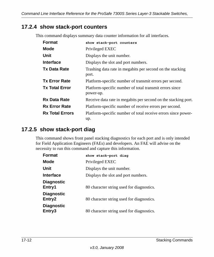
Command Line Interface Reference for the ProSafe 7300S Series Layer-3 Stackable Switches,
17.2.4 show stack-port countersThis command displays summary data counter information for all interfaces.
Format show stack-port counters
Mode Privileged EXECUnit Displays the unit number.Interface Displays the slot and port numbers.Tx Data Rate Trashing data rate in megabits per second on the stacking
port.Tx Error Rate Platform-specific number of transmit errors per second.Tx Total Error Platform-specific number of total transmit errors since
power-up.Rx Data Rate Receive data rate in megabits per second on the stacking port.Rx Error Rate Platform-specific number of receive errors per second.Rx Total Errors Platform-specific number of total receive errors since power-
up.
17.2.5 show stack-port diagThis command shows front panel stacking diagnostics for each port and is only intended for Field Application Engineers (FAEs) and developers. An FAE will advise on the necessity to run this command and capture this information.
Format show stack-port diag
Mode Privileged EXECUnit Displays the unit number.Interface Displays the slot and port numbers.Diagnostic Entry1 80 character string used for diagnostics.Diagnostic Entry2 80 character string used for diagnostics.Diagnostic Entry3 80 character string used for diagnostics.
17-12 Stacking Commands
v3.0, January 2008

Chapter 18System Maintenance Commands
This section describes the system maintenance commands available in the 7300S Series Stackable Switch CLI.
The System Maintenance Commands section includes the following subsections:
• Section 18.1 “System Information and Statistics Commands” on page 18-1• Section 18.2 “System Utility Commands” on page 18-18• Section 18.3 “Logging Commands” on page 18-23• Section 18.4 “CLI Command Logging Command” on page 18-28• Section 18.5 “Configuration Scripting Commands” on page 18-29
The commands in this section are in one of four functional groups:
• Show commands display switch settings, statistics, and other information.
• Configuration commands configure features and options of the switch. For every configuration command, there is a show command that displays the configuration setting.
• Copy commands transfer or save configuration and informational files to and from the switch.
• Clear commands clear some or all of the settings to factory defaults.
18.1 System Information and Statistics CommandsThis section describes the commands you use to view information about system features, components, and configurations.
18.1.1 show arp switchThis command displays connectivity between the switch and other devices. The Address Resolution Protocol (ARP) cache identifies the MAC addresses of the IP stations communicating with the switch.
Format show arp switch
System Maintenance Commands 18-1
v3.0, January 2008

Command Line Interface Reference for the ProSafe 7300S Series Layer-3 Stackable Switches,
Mode Privileged EXEC MAC Address A unicast MAC address for which the switch has forwarding
and/or filtering information. The format is 6 two-digit hexa-decimal numbers that are separated by colons, for example 01:23:45:67:89:AB
IP Address The IP address assigned to each interface.Interface Valid slot and port number separated by forward slashes.
18.1.2 show eventlogThis command displays the event log, which contains error messages from the system. The event log is not cleared on a system reset. The [unit] is the switch identifier.
Format show eventlog [unit]
Mode Privileged EXEC File The file in which the event originated. Line The line number of the eventTask Id The task ID of the event. Code The event code. Time The time this event occurred. Unit The unit for the event.
18.1.3 show hardwareThis command displays inventory information for the switch.
Format show hardware Mode Privileged EXECSwitch Description Text used to identify the product name of this switch.Machine Type Specifies the machine model as defined by the Vital Product
Data.
Note: Event log information is retained across a switch reset.
18-2 System Maintenance Commands
v3.0, January 2008

Command Line Interface Reference for the ProSafe 7300S Series Layer-3 Stackable Switches,
Machine Model Specifies the machine model as defined by the Vital Product Data.
Serial Number The unique box serial number for this switch.FRU Number The field replaceable unit number.Part Number Manufacturing part number.Maintenance Level Indicates hardware changes that are significant to software.Manufacturer Manufacturer descriptor field.Burned in MAC Address Universally assigned network address.Software Version The release.version.revision number of the code currently
running on the switch.Operating System The operating system currently running on the switch.Network Processing Device The type of the processor microcode. Additional Packages This displays the additional packages incorporated into this
system.
18.1.4 show interface This command displays a summary of statistics for a specific interface or a count of all CPU traffic based upon the argument.
Format show interface {<unit/slot/port> | switchport | ethernet}
Mode Privileged EXEC
The display parameters, when the argument is <unit/slot/port>, is as follows:
Note: For information about the format and output for show interface ethernet, see Section 18.1.5 “show interface ethernet” on page 18-5.
System Maintenance Commands 18-3
v3.0, January 2008

Command Line Interface Reference for the ProSafe 7300S Series Layer-3 Stackable Switches,
Packets Received Without Error The total number of packets (including broadcast packets and
multicast packets) received by the processor. Packets Received With Error The number of inbound packets that contained errors prevent-
ing them from being deliverable to a higher-layer protocol. Broadcast Packets Received The total number of packets received that were directed to the
broadcast address. Note that this does not include multicast packets.
Packets Transmitted Without Error Total number of packets transmitted out the interface. Transmit Packets Errors Number of outbound packets that could not be transmitted
because of errors. Collisions Frames Best estimate of the total number of collisions on this Ether-
net segment. Time Since Counters Last Cleared Elapsed time, in days, hours, minutes, and seconds since the
statistics for this port were last cleared.
If you use the switchport parameter, the following information appears:Packets Received Without Error The total number of packets (including broadcast packets and
multicast packets) received by the processor. Broadcast Packets Received The total number of packets received that were directed to the
broadcast address. Note that this does not include multicast packets.
Packets Received With Error The number of inbound packets that contained errors prevent-
ing them from being deliverable to a higher-layer protocol.
18-4 System Maintenance Commands
v3.0, January 2008
Command Line Interface Reference for the ProSafe 7300S Series Layer-3 Stackable Switches,
Packets Transmitted Without Error Total number of packets transmitted out the interface. Broadcast Packets Transmitted The total number of packets that higher-level protocols
requested to be transmitted to the Broadcast address, includ-ing those that were discarded or not sent.
Transmit Packet Errors The number of outbound packets that could not be transmit-
ted because of errors. Address Entries Currently In Use The total number of Forwarding Database Address Table
entries now active on the switch, including learned and static entries.
VLAN Entries Currently In Use The number of VLAN entries presently occupying the VLAN
table. Time Since Counters Last Cleared The elapsed time, in days, hours, minutes, and seconds since
the statistics for this switch were last cleared.
18.1.5 show interface ethernetThis command displays detailed statistics for a specific interface or for all CPU traffic based upon the argument.
Format show interface ethernet {<unit/slot/port> | switch-port}
Mode Privileged EXEC
The display parameters, when the argument is <unit/slot/port>, are as follows:Packets Received Octets Received - The total number of octets of data (includ-
ing those in bad packets) received on the network (excluding framing bits but including Frame Check Sequence (FCS) octets). This object can be used as a reasonable estimate of Ethernet utilization. If greater precision is desired, the ether-
System Maintenance Commands 18-5
v3.0, January 2008

Command Line Interface Reference for the ProSafe 7300S Series Layer-3 Stackable Switches,
StatsPkts and etherStatsOctets objects should be sampled before and after a common interval. The result of this equa-tion is the value Utilization which is the percent utilization of the Ethernet segment on a scale of 0 to 100 percent. Packets Received < 64 Octets - The total number of packets (including bad packets) received that were < 64 octets in length (excluding framing bits but including FCS octets). Packets Received 64 Octets - The total number of packets (including bad packets) received that were 64 octets in length (excluding framing bits but including FCS octets). Packets Received 65-127 Octets - The total number of pack-ets (including bad packets) received that were between 65 and 127 octets in length inclusive (excluding framing bits but including FCS octets). Packets Received 128-255 Octets - The total number of packets (including bad packets) received that were between 128 and 255 octets in length inclusive (excluding framing bits but including FCS octets). Packets Received 256-511 Octets - The total number of packets (including bad packets) received that were between 256 and 511 octets in length inclusive (excluding framing bits but including FCS octets). Packets Received 512-1023 Octets - The total number of packets (including bad packets) received that were between 512 and 1023 octets in length inclusive (excluding framing bits but including FCS octets). Packets Received 1024-1518 Octets - The total number of packets (including bad packets) received that were between 1024 and 1518 octets in length inclusive (excluding framing bits but including FCS octets). Packets Received 1519-1522 Octets - The total number of packets (including bad packets) received that were between 1519 and 1522 octets in length inclusive (excluding framing bits but including FCS octets). Packets Received > 1522 Octets - The total number of pack-ets received that were longer than 1522 octets (excluding framing bits, but including FCS octets) and were otherwise well formed.
18-6 System Maintenance Commands
v3.0, January 2008

Command Line Interface Reference for the ProSafe 7300S Series Layer-3 Stackable Switches,
Packets Received Successfully Total - The total number of packets received that were with-
out errors. Unicast Packets Received - The number of subnetwork-uni-cast packets delivered to a higher-layer protocol. Multicast Packets Received - The total number of good packets received that were directed to a multicast address. Note that this number does not include packets directed to the broadcast address. Broadcast Packets Received - The total number of good packets received that were directed to the broadcast address. Note that this does not include multicast packets.
Packets Received with MAC Errors Total - The total number of inbound packets that contained
errors preventing them from being deliverable to a higher-layer protocol. Jabbers Received - The total number of packets received that were longer than 1518 octets (excluding framing bits, but including FCS octets), and had either a bad Frame Check Sequence (FCS) with an integral number of octets (FCS Error) or a bad FCS with a non-integral number of octets (Alignment Error). Note that this definition of jabber is dif-ferent than the definition in IEEE-802.3 section 8.2.1.5 (10BASE5) and section 10.3.1.4 (10BASE2). These docu-ments define jabber as the condition where any packet exceeds 20 ms. The allowed range to detect jabber is between 20 ms and 150 ms. Fragments/Undersize Received - The total number of packets received that were less than 64 octets in length (excluding framing bits but including FCS octets). Alignment Errors - The total number of packets received that had a length (excluding framing bits, but including FCS octets) of between 64 and 1518 octets, inclusive, but had a bad Frame Check Sequence (FCS) with a non-integral num-ber of octets. Rx FCS Errors - The total number of packets received that had a length (excluding framing bits, but including FCS octets) of between 64 and 1518 octets, inclusive, but had a
System Maintenance Commands 18-7
v3.0, January 2008

Command Line Interface Reference for the ProSafe 7300S Series Layer-3 Stackable Switches,
bad Frame Check Sequence (FCS) with an integral number of octets Overruns - The total number of frames discarded as this port was overloaded with incoming packets, and could not keep up with the inflow.
Received Packets Not Forwarded Total - A count of valid frames received which were dis-
carded (in other words, filtered) by the forwarding process. Local Traffic Frames - The total number of frames dropped in the forwarding process because the destination address was located off of this port. 802.3x Pause Frames Received - A count of MAC Control frames received on this interface with an opcode indicating the PAUSE operation. This counter does not increment when the interface is operating in half-duplex mode. Unacceptable Frame Type - The number of frames dis-carded from this port due to being an unacceptable frame type. VLAN Membership Mismatch - The number of frames dis-carded on this port due to ingress filtering. VLAN Viable Discards - The number of frames discarded on this port when a lookup on a particular VLAN occurs while that entry in the VLAN table is being modified, or if the VLAN has not been configured. Multicast Tree Viable Discards - The number of frames dis-carded when a lookup in the multicast tree for a VLAN occurs while that tree is being modified. Reserved Address Discards - The number of frames dis-carded that are destined to an IEEE 802.1 reserved address and are not supported by the system. Broadcast Storm Recovery - The number of frames dis-carded that are destined for FF:FF:FF:FF:FF:FF when Broad-cast Storm Recovery is enabled. CFI Discards - The number of frames discarded that have CFI bit set and the addresses in RIF are in non-canonical for-mat.
18-8 System Maintenance Commands
v3.0, January 2008

Command Line Interface Reference for the ProSafe 7300S Series Layer-3 Stackable Switches,
Upstream Threshold - The number of frames discarded due to lack of cell descriptors available for that packet's priority level.
Packets Transmitted Octets Total Bytes - The total number of octets of data (including
those in bad packets) received on the network (excluding framing bits but including FCS octets). This object can be used as a reasonable estimate of Ethernet utilization. If greater precision is desired, the etherStatsPkts and etherStat-sOctets objects should be sampled before and after a common interval. ----- Packets Transmitted 64 Octets - The total number of pack-ets (including bad packets) received that were 64 octets in length (excluding framing bits but including FCS octets). Packets Transmitted 65-127 Octets - The total number of packets (including bad packets) received that were between 65 and 127 octets in length inclusive (excluding framing bits but including FCS octets). Packets Transmitted 128-255 Octets - The total number of packets (including bad packets) received that were between 128 and 255 octets in length inclusive (excluding framing bits but including FCS octets). Packets Transmitted 256-511 Octets - The total number of packets (including bad packets) received that were between 256 and 511 octets in length inclusive (excluding framing bits but including FCS octets). Packets Transmitted 512-1023 Octets - The total number of packets (including bad packets) received that were between 512 and 1023 octets in length inclusive (excluding framing bits but including FCS octets). Packets Transmitted 1024-1518 Octets - The total number of packets (including bad packets) received that were between 1024 and 1518 octets in length inclusive (excluding framing bits but including FCS octets). Packets Transmitted 1519-1522 Octets - The total number of packets (including bad packets) received that were between 1519 and 1522 octets in length inclusive (excluding framing bits but including FCS octets).
System Maintenance Commands 18-9
v3.0, January 2008

Command Line Interface Reference for the ProSafe 7300S Series Layer-3 Stackable Switches,
Max Info - The maximum size of the Info (non-MAC) field that this port will receive or transmit.
Packets Transmitted Successfully Total - The number of frames that have been transmitted by
this port to its segment. Unicast Packets Transmitted - The total number of packets that higher-level protocols requested be transmitted to a sub-network-unicast address, including those that were discarded or not sent. Multicast Packets Transmitted - The total number of pack-ets that higher-level protocols requested be transmitted to a Multicast address, including those that were discarded or not sent. Broadcast Packets Transmitted - The total number of pack-ets that higher-level protocols requested be transmitted to the Broadcast address, including those that were discarded or not sent.
Transmit Errors Total Errors - The sum of Single, Multiple, and Excessive Collisions. Tx FCS Errors - The total number of packets transmitted that had a length (excluding framing bits, but including FCS octets) of between 64 and 1518 octets, inclusive, but had a bad Frame Check Sequence (FCS) with an integral number of octets Oversized - The total number of frames that exceeded the max permitted frame size. This counter has a max increment rate of 815 counts per sec. at 10 Mb/s. Underrun Errors - The total number of frames discarded because the transmit FIFO buffer became empty during frame transmission.
Transmit Discards Total Discards - The sum of single collision frames dis-
carded, multiple collision frames discarded, and excessive frames discarded. Single Collision Frames - A count of the number of success-fully transmitted frames on a particular interface for which transmission is inhibited by exactly one collision.
18-10 System Maintenance Commands
v3.0, January 2008

Command Line Interface Reference for the ProSafe 7300S Series Layer-3 Stackable Switches,
Multiple Collision Frames - A count of the number of suc-cessfully transmitted frames on a particular interface for which transmission is inhibited by more than one collision. Excessive Collisions - A count of frames for which transmis-sion on a particular interface fails due to excessive collisions. Port Membership - The number of frames discarded on egress for this port due to egress filtering being enabled. VLAN Viable Discards - The number of frames discarded on this port when a lookup on a particular VLAN occurs while that entry in the VLAN table is being modified, or if the VLAN has not been configured.
Protocol Statistics BPDU's received - The count of BPDU's (Bridge Protocol
Data Units) received in the spanning tree layer. BPDU's Transmitted - The count of BPDU's (Bridge Proto-col Data Units) transmitted from the spanning tree layer. 802.3x Pause Frames Received - A count of MAC Control frames received on this interface with an opcode indicating the PAUSE operation. This counter does not increment when the interface is operating in half-duplex mode. GVRP PDU's Received - The count of GVRP PDU's received in the GARP layer.GVRP PDU's Transmitted - The count of GVRP PDU's transmitted from the GARP layer. GVRP Failed Registrations - The number of times attempted GVRP registrations could not be completed. GMRP PDU's received - The count of GMRP PDU's received in the GARP layer. GMRP PDU's Transmitted - The count of GMRP PDU's transmitted from the GARP layer. GMRP Failed Registrations - The number of times attempted GMRP registrations could not be completed. STP BPDUs Transmitted - Spanning Tree Protocol Bridge Protocol Data Units sentSTP BPDUs Received - Spanning Tree Protocol Bridge Pro-tocol Data Units receivedRST BPDUs Transmitted - Rapid Spanning Tree Protocol Bridge Protocol Data Units sent
System Maintenance Commands 18-11
v3.0, January 2008

Command Line Interface Reference for the ProSafe 7300S Series Layer-3 Stackable Switches,
RSTP BPDUs Received - Rapid Spanning Tree Protocol Bridge Protocol Data Units receivedMSTP BPDUs Transmitted - Multiple Spanning Tree Proto-col Bridge Protocol Data Units sentMSTP BPDUs Received - Multiple Spanning Tree Protocol Bridge Protocol Data Units received
Dot1x Statistics EAPOL Frames Received - The number of valid EAPOL frames of any type that have been received by this authentica-tor. EAPOL Frames Transmitted - The number of EAPOL frames of any type that have been transmitted by this authen-ticator.
Time Since Counters Last Cleared The elapsed time, in days, hours, minutes, and seconds since
the statistics for this port were last cleared.
If you specify the switchport value, the following information appears:Octets Received - The total number of octets of data received by the processor (excluding framing bits but including FCS octets). Total Packets Received Without Error- The total number of packets (including broadcast packets and multicast pack-ets) received by the processor. Unicast Packets Received - The number of subnetwork-uni-cast packets delivered to a higher-layer protocol. Multicast Packets Received - The total number of packets received that were directed to a multicast address. Note that this number does not include packets directed to the broad-cast address. Broadcast Packets Received - The total number of packets received that were directed to the broadcast address. Note that this does not include multicast packets. Receive Packets Discarded - The number of inbound pack-ets which were chosen to be discarded even though no errors had been detected to prevent their being deliverable to a higher-layer protocol. A possible reason for discarding a packet could be to free up buffer space.
18-12 System Maintenance Commands
v3.0, January 2008

Command Line Interface Reference for the ProSafe 7300S Series Layer-3 Stackable Switches,
Octets Transmitted - The total number of octets transmitted out of the interface, including framing characters. Packets Transmitted without Errors - The total number of packets transmitted out of the interface. Unicast Packets Transmitted - The total number of packets that higher-level protocols requested be transmitted to a sub-network-unicast address, including those that were discarded or not sent. Multicast Packets Transmitted - The total number of pack-ets that higher-level protocols requested be transmitted to a Multicast address, including those that were discarded or not sent. Broadcast Packets Transmitted - The total number of pack-ets that higher-level protocols requested be transmitted to the Broadcast address, including those that were discarded or not sent. Transmit Packets Discarded - The number of outbound packets which were chosen to be discarded even though no errors had been detected to prevent their being deliverable to a higher-layer protocol. A possible reason for discarding a packet could be to free up buffer space. Most Address Entries Ever Used - The highest number of Forwarding Database Address Table entries that have been learned by this switch since the most recent reboot. Address Entries in Use - The number of Learned and static entries in the Forwarding Database Address Table for this switch. Maximum VLAN Entries - The maximum number of Vir-tual LANs (VLANs) allowed on this switch. Most VLAN Entries Ever Used - The largest number of VLANs that have been active on this switch since the last reboot. Static VLAN Entries - The number of presently active VLAN entries on this switch that have been created statically. Dynamic VLAN Entries - The number of presently active VLAN entries on this switch that have been created by GVRP registration.
System Maintenance Commands 18-13
v3.0, January 2008

Command Line Interface Reference for the ProSafe 7300S Series Layer-3 Stackable Switches,
VLAN Deletes - The number of VLANs on this switch that have been created and then deleted since the last reboot.
Time Since Counters Last Cleared The elapsed time, in days, hours, minutes, and seconds, since
the statistics for this switch were last cleared.
18.1.6 show loggingThis command displays the trap log that the switch maintains. The trap log contains a maximum of 256 entries that wrap.
Format show logging
Mode Privileged EXEC Number of Traps since last reset The number of traps that have occurred since the last reset. Number of Traps since log last displayed The number of traps that have occurred since the traps were
last displayed. Getting the traps by any method (terminal interface display, Web display, upload file from switch etc.) sets the counter to 0.
Log The sequence number of this trap. System Up Time The relative time since the last reboot of the switch at which
this trap occurred. Trap The relevant information of this trap.
Note: Trap log information is not retained across a switch reset.
18-14 System Maintenance Commands
v3.0, January 2008

Command Line Interface Reference for the ProSafe 7300S Series Layer-3 Stackable Switches,
18.1.7 show mac-addr-tableThis command displays the forwarding database entries. If the command is entered with no parameter, the entire table is displayed. This is the same as entering the optional all parameter. Alternatively, the administrator can enter a MAC Address to display the table entry for the requested MAC address and all entries following the requested MAC address. If the <unit/slot/port> is used, then the MAC addresses learned on that port is displayed. If the VLAN option is used, then all the MAC addresses learned on that VLAN are reported.
Format show mac-addr-table [<macaddr> |<unit/slot/port> | VLAN <id>| all]
Mode Privileged EXEC Mac Address A unicast MAC address for which the switch has forwarding
and or filtering information. The format is 6 or 8 two-digit hexadecimal numbers that are separated by colons, for exam-ple 01:23:45:67:89:AB. In an IVL system the MAC address will be displayed as 8 bytes.
Interface The port which this address was learned.Interface Index This object indicates the ifIndex of the interface table entry
associated with this port.Status The status of this entry. The meanings of the values are:Static The value of the corresponding instance was added by the
system or a user when a static MAC filter was defined. It can-not be relearned.
Learned The value of the corresponding instance was learned by observing the source MAC addresses of incoming traffic, and is currently in use.
Management The value of the corresponding instance (system MAC address) is also the value of an existing instance of dot1dStaticAddress. It is identified with port number one and is currently used when enabling VLANs for routing.
System Maintenance Commands 18-15
v3.0, January 2008

Command Line Interface Reference for the ProSafe 7300S Series Layer-3 Stackable Switches,
Self The value of the corresponding instance is the address of one of the switch’s physical interfaces (the system’s own MAC address).
GMRP Learned The value was learned via GMRP and applies to Multicast.Other The value of the instance does not fall into one of the other
categories.
18.1.8 clear mac-addr-tableThis command clears the dynamically learned MAC addresses of the switch.
Format clear mac-addr-table Mode Privileged EXEC
18.1.9 show running-configUse this command to display/capture the current setting of different protocol packages supported on the switch. This command displays/captures commands with settings/configurations that differ from the default value. To display/capture the commands with settings/configurations that are equal to the default value, include the [all] option.
The output is displayed in script format, which can be used to configure another switch with the same configuration. If the optional <scriptname> is provided with a file name extension of “.scr”, the output is redirected to a script file.
If option <changed> is used, this command displays/capture commands with settings/configurations that differ from the defaul value.
Format show running-config [all | <scriptname> | changed]
Mode Privileged EXEC
18.1.10 show running-config interfaceThis command shows the current configuration on a particular interface. The interface could be a physical port or a virtual port—like a LAG or VLAN. The output captures how the configuration differs from the factory default value.
Format show running-config interface {<unit/slot/port>} | VLAN <id> | LAG <id>}
Mode Interface config
18-16 System Maintenance Commands
v3.0, January 2008

Command Line Interface Reference for the ProSafe 7300S Series Layer-3 Stackable Switches,
18.1.11 terminal lengthThis command controls the number of lines to be displayed when running the show running-config command.
Format terminal length <1-24>Mode Privileged EXEC
18.1.11.1 terminal no lengthThis command resets the number of lines displayed when running the show running-config command to the default value (18).
Format terminal no length
Mode Privileged EXEC
18.1.12 show sysinfoThis command displays switch information.
Format show sysinfo Mode Privileged EXEC Switch Description Text used to identify this switch.System Name Name used to identify the switch.The factory default is blank.
To configure the system name, see Section 10.1.1 “snmp-server” on page 10-1.
System Location Text used to identify the location of the switch. The factory default is blank. To configure the system location, see Section 10.1.1 “snmp-server” on page 10-1.
System Contact Text used to identify a contact person for this switch. The fac-tory default is blank. To configure the system location, see Section 10.1.1 “snmp-server” on page 10-1.
System ObjectID The base object ID for the switch’s enterprise MIB.System Up Time The time in days, hours and minutes since the last switch
reboot.MIBs Supported A list of MIBs supported by this agent.
System Maintenance Commands 18-17
v3.0, January 2008
Command Line Interface Reference for the ProSafe 7300S Series Layer-3 Stackable Switches,
18.2 System Utility CommandsThis section describes the commands you use to help troubleshoot connectivity issues and to restore various configurations to their factory defaults.
18.2.1 traceroute Use the traceroute command to discover the routes that packets actually take when traveling to their destination through the network on a hop-by-hop basis. The <ipaddr> value should be a valid IP address. The [port] value should be a valid decimal integer in the range of 0(zero) to 65535. The default value is 33434.
The optional port parameter is the UDP port used as the destination of packets sent as part of the traceroute. This port should be an unused port on the destination system.
Format traceroute <ipaddr> [port]
Mode Privileged EXEC
18.2.2 clear configThis command resets the configuration to the factory defaults without powering off the switch. When you issue this command, a prompt appears to confirm that the reset should proceed. When you enter y, you automatically reset the switch.
Format clear config Mode Privileged EXEC
18.2.3 clear countersThis command clears the statistics for a specified <unit/slot/port>, for all the ports, or for the entire switch based upon the argument.
Format clear counters {<unit/slot/port> | all}
Mode Privileged EXEC
18.2.4 clear igmpsnooping This command clears the tables managed by the IGMP Snooping function and attempts to delete these entries from the Multicast Forwarding Database.
Format clear igmpsnooping
Mode Privileged EXEC
18-18 System Maintenance Commands
v3.0, January 2008

Command Line Interface Reference for the ProSafe 7300S Series Layer-3 Stackable Switches,
18.2.5 clear passThis command resets all user passwords to the factory defaults without powering off the switch. You are prompted to confirm that the password reset should proceed.
Format clear pass
Mode Privileged EXEC
18.2.6 enable passwdThis command prompts you to change the Privileged EXEC password.
Format enable passwd
Mode User EXEC
System Maintenance Commands 18-19
v3.0, January 2008

Command Line Interface Reference for the ProSafe 7300S Series Layer-3 Stackable Switches,
18.2.7 clear port-channelThis command clears all port-channels (LAGs).
Format clear port-channel
Mode Privileged EXEC
18.2.8 clear traplogThis command clears the trap log.
Format clear traplog Mode Privileged EXEC
18.2.9 clear vlanThis command resets VLAN configuration parameters to the factory defaults.
Format clear vlan
Mode Privileged EXEC
18.2.10 copyThe copy command uploads and downloads files to and from the switch. You can upload and download files from a server by using TFTP, Xmodem, Ymodem, or Zmodem.
Format copy <source> <destination>Mode Global Config
Replace the <source> and <destination> parameters with the options in Table 18-1. For the <url> source or destination, use one of the following values:xmodem | ymodem | zmodem | tftp://<ipaddr>/<filepath>/<filename>
For TFTP, the <ipaddr> parameter is the IP address of the server, <filepath> is the path to the file, and <filename> is the name of the file you want to upload or download.
Table 18-1. Copy Parameters
Source Destination Description
nvram:clibanner <url> Copies the CLI banner to a server.
nvram:errorlog <url> Copies the error log file to a server.
nvram:log <url> Copies the log file to a server.
nvram:script <scriptname>
<url> Copies a specified configuration script file to a server.
18-20 System Maintenance Commands
v3.0, January 2008

Command Line Interface Reference for the ProSafe 7300S Series Layer-3 Stackable Switches,
nvram:startup-config <url> Copies the startup configuration to a server.
nvram:traplog <url> Copies the trap log file to a server.
system:running-config nvram:startup-config Saves the running configuration to nvram.
<url> nvram:clibanner Downloads the CLI banner to the system.
<url> nvram:script <destfilename>
Downloads a configuration script file to the system. During the download of a configuration script, the copy command validates the script. In case of any error, the command lists all the lines at the end of the validation process and prompts you to confirm before copying the script file.
<url> nvram:sshkeydsa Downloads an SSH key file. For more information, see Section 3.5 “Secure Shell (SSH) Command” on page 3-15.
<url> nvram:sshkeyrsa1 Downloads an SSH key file.
<url> nvram:sshkeyrsa1 Downloads an SSH key file.
<url> nvram:sslpemroot Downloads an HTTP secure-server certificate. For more information, see Section 3.6 “Hypertext Transfer Protocol (HTTP) Commands” on page 3-17.
<url> nvram:sslpemserver Downloads an HTTP secure-server certificate.
<url> nvram:sslpemdhweak Downloads an HTTP secure-server certificate.
<url> nvram:sslpemdhstrong
Downloads an HTTP secure-server certificate.
<url> nvram:startup-config Downloads the startup configuration file to the system.
<url> system:image Downloads a code image to the system.
Table 18-1. Copy Parameters (continued)
Source Destination Description
System Maintenance Commands 18-21
v3.0, January 2008
Command Line Interface Reference for the ProSafe 7300S Series Layer-3 Stackable Switches,
18.2.11 logoutThis command closes the current telnet connection or resets the current serial connection.
Format logout
Mode Privileged EXEC
18.2.12 pingThis command checks if another computer is on the network and listens for connections. To use this command, configure the switch for network (in-band) connection. The source and target devices must have the ping utility enabled and running on top of TCP/IP. You can ping the switch from any IP workstation the switch is connected to through the default VLAN (VLAN 1), as long as there is a physical path between the switch and the workstation. The terminal interface sends three pings to the target station.
Format ping <ipaddr>
Modes Privileged EXEC, User EXEC
18.2.13 reloadThis command resets the switch without powering it off. Reset means that all network connections are terminated and the boot code executes. The switch uses the stored configuration to initialize the switch. You are prompted to confirm that the reset should proceed. The LEDs on the switch indicate a successful reset.
Format reload Mode Privileged EXEC
Note: Save configuration changes before logging out.
18-22 System Maintenance Commands
v3.0, January 2008

Command Line Interface Reference for the ProSafe 7300S Series Layer-3 Stackable Switches,
18.3 Logging CommandsThis section describes the commands you use to configure system logging, and to view logs and the logging settings.
18.3.1 logging bufferedThis command enables logging to an in-memory log that keeps up to 128 logs.
Default disabled; criticalFormat logging buffered
Mode Global Config
18.3.1.1 no logging bufferedThis command disables logging to in-memory log.
Format no logging buffered
Mode Global Config
18.3.2 logging buffered wrapThis command enables wrapping of in-memory logging when the log file reaches full capacity. Otherwise when the log file reaches full capacity, logging stops.
Default enabledFormat logging buffered wrap
Mode Privileged EXEC
18.3.2.1 no logging wrapThis command disables wrapping of in-memory logging and configures logging to stop when the log file capacity is full.
Format no logging buffered wrap
Mode Privileged EXEC
System Maintenance Commands 18-23
v3.0, January 2008

Command Line Interface Reference for the ProSafe 7300S Series Layer-3 Stackable Switches,
18.3.3 logging consoleThis command enables logging to the console. You can specify the <severitylevel> value as either an integer from 0 to 7 or symbolically through one of the following keywords: emergency (0), alert (1), critical (2), error (3), warning (4), notice (5), informational (6), or debug (7).
Default disabled; criticalFormat logging console [severitylevel]
Mode Global Config
18.3.3.1 no logging consoleThis command disables logging to the console.
Format no logging console
Mode Global Config
18.3.4 logging hostThis command enables logging to a host. You can configure up to eight hosts. The <ipaddr> is the IP address of the logging host. The <port> value is a port number from 1 to 65535. You can specify the <severitylevel> value as either an integer from 0 to 7 or symbolically through one of the following keywords: emergency (0), alert (1), critical (2), error (3), warning (4), notice (5), informational (6), or debug (7).
Default port - 514; level - critical; Format logging host <ipaddr> [<port>][<severitylevel>]
Mode Global Config
18.3.5 logging host removeThis command disables logging to host. See Section 18.3.11 “show logging hosts” on page 18-27 for a list of host indexes.
Format logging host remove <hostindex>
Mode Global Config
18-24 System Maintenance Commands
v3.0, January 2008

Command Line Interface Reference for the ProSafe 7300S Series Layer-3 Stackable Switches,
18.3.6 logging portThis command sets the local port number of the LOG client for logging messages. The <portid> can be in the range from 1 to 65535.
Default 514Format logging port <portid>
Mode Global Config
18.3.6.1 no logging portThis command resets the local logging port to the default.
Format no logging port
Mode Global Config
18.3.7 logging syslogThis command enables syslog logging.
Default disabled; local0Format logging syslog
Mode Global Config
18.3.7.1 no logging syslogThis command disables syslog logging.
Format no logging syslog
Mode Global Config
18.3.8 show logging This command displays logging.
Format show logging
Mode Privileged EXECClient Local Port The port on the collector/relay to which syslog messages are
sent.Console Logging Administrative Mode The mode for console logging.
System Maintenance Commands 18-25
v3.0, January 2008

Command Line Interface Reference for the ProSafe 7300S Series Layer-3 Stackable Switches,
Console Logging Severity Filter The minimum severity to log to the console log. Messages
with an equal or lower numerical severity are logged.Buffered Logging Administrative Mode The mode for buffered logging.Buffered Logging Severity Filter The minimum severity to log to the buffered log. Messages
with an equal or lower numerical severity are logged.Historical Logging Administrative Mode The mode for historical logging.Historical Logging Severity Filter The minimum severity to log to the historical log. Messages
with an equal or lower numerical severity are logged.Syslog Logging Administrative Mode The mode for logging to configured syslog hosts. If set to dis-
able logging stops to all syslog hosts. Log Messages Received The number of messages received by the log process. This
includes messages that are dropped or ignoredLog Messages Dropped The number of messages that could not be processed.
18-26 System Maintenance Commands
v3.0, January 2008

Command Line Interface Reference for the ProSafe 7300S Series Layer-3 Stackable Switches,
18.3.9 show logging bufferedThis command displays buffered logging (system startup and system operation logs).
Format show logging buffered
Mode Privileged EXECAdmin Status The current state of the in-memory log.Component Filter The component(s) from which received messages are to be
logged to the in memory log. Either a single component id or “all components” may be specified.
Wrapping Behavior The behavior of the In Memory log when faced with a log
full situation.Log Count The count of valid entries in the buffered log.
18.3.10 clear logging bufferedThis command clears the messages maintained in the system log.
Format clear logging buffered
Mode Privileged EXEC
18.3.11 show logging hostsThis command displays all configured logging hosts.
Format show logging hosts
Mode Privileged EXECHost Index (Used for deleting hosts)Severity Level The minimum severity to log to the specified address.Port Displays the server port number, which is the port on the
local host from which syslog messages are sent.Host Status The state of logging to configured syslog hosts. If the status is
disable, no logging occurs.
System Maintenance Commands 18-27
v3.0, January 2008

Command Line Interface Reference for the ProSafe 7300S Series Layer-3 Stackable Switches,
18.3.12 show logging traplogsThis command displays SNMP trap events and statistics.
Format show logging traplogs
Mode Privileged EXECNumber of Traps Since Last Reset Shows the number of traps since the last boot.Trap Log Capacity Shows the number of traps the system can retain.Number of Traps Since Log Last Viewed Shows the number of new traps since the command was last
executed. Log Shows the log number.System Time Up Shows how long the system had been running at the time the
trap was sent.Trap Shows the text of the trap message.
18.4 CLI Command Logging CommandThis section describes the commands you use to configure CLI Command Logging.
18.4.1 logging cli-commandThis command enables the CLI command logging feature, which enables the 7300S Series Stackable Switch software to log all CLI commands issued on the system.
Default enabledFormat logging cli-command
Mode Global Config
18.4.1.1 no logging cli-commandThis command disables the CLI command Logging feature.
Format no logging cli-command
Mode Global Config
18-28 System Maintenance Commands
v3.0, January 2008

Command Line Interface Reference for the ProSafe 7300S Series Layer-3 Stackable Switches,
18.5 Configuration Scripting CommandsConfiguration Scripting allows you to generate text-formatted script files representing the current configuration of a system. You can upload these configuration script files to a PC or UNIX system and edit them. Then, you can download the edited files to the system and apply the new configuration. You can apply configuration scripts to one or more switches with no or minor modifications.
Use the show running-config command (see Section 18.1.9 “show running-config” on page 18-16) to capture the running configuration into a script. Use the copy command (see Section 18.2.10 “copy” on page 18-20) to transfer the configuration script to or from the switch.
You should use scripts on systems with default configuration; however, you are not prevented from applying scripts on systems with non-default configurations.
Scripts must conform to the following rules:
• Script files are not distributed across the stack, and only live in the unit that is the master unit at the time of the file download.
• The file extension must be “.scr”.
• A maximum of ten scripts are allowed on the switch.
• The combined size of all script files on the switch shall not exceed 2048 KB.
• The maximum number of configuration file command lines is 2000.
You can type single-line annotations at the command prompt to use when you write test or configuration scripts to improve script readability. The exclamation point (!) character flags the beginning of a comment. The comment flag character can begin a word anywhere on the command line, and all input following this character is ignored. Any command line that begins with the “!” character is recognized as a comment line and ignored by the parser.
The following lines show an example of a script:! Script file for displaying the ip interface! Display information about interfacesshow ip interface 1/0/1 !Displays the information about the first interface! Display information about the next interfaceshow ip interface 1/0/2! End of the script file
System Maintenance Commands 18-29
v3.0, January 2008

Command Line Interface Reference for the ProSafe 7300S Series Layer-3 Stackable Switches,
18.5.1 script applyThis command applies the commands in the script to the switch. The <scriptname> parameter is the name of the script to apply.
Format script apply <scriptname>Mode Global Config
18.5.2 script deleteThis command deletes a specified script where the <scriptname> parameter is the name of the script to delete. The <all> option deletes all the scripts present on the switch.
Format script delete {<scriptname> | all} Mode Global Config
18.5.3 script listThis command lists all scripts present on the switch as well as the remaining available space.
Format script list
Mode Global ConfigConfiguration Script Name of the script.Size Size of the script.
18.5.4 show scriptThis command displays the contents of a script file, which is named <scriptname>.
Format show script <scriptname>Mode Global ConfigOutput Format line <number>: <line contents>
18-30 System Maintenance Commands
v3.0, January 2008

Command Line Interface Reference for the ProSafe 7300S Series Layer-3 Stackable Switches,
18.5.5 script validateThis command validates a script file by parsing each line in the script file where <scriptname> is the name of the script to validate.The validate option is intended to be used as a tool for script development. Validation identifies potential problems. It might not identify all problems with a given script on any given device.
Format script validate <scriptname> Mode Global Config
18.6 Packet CapturePacket capture commands assist in troubleshooting protocol-related problems with the management CPU. The packets to and from the management CPU can be captured in an internally allocated buffer area for export to a PC host for protocol analysis. Public domain packet analysis tools like Ethereal can be used to decode and review the packets in detail. Capturing can be performed in a variety of modes, either transmit-side only, receive-side only, or both. The number of packets captured will depend on the size of the captured packets.
18.6.1 capture transmit packetThis command enables the capturing of transmit packets.
Format capture transmit packet
Mode Global Config
18.6.1.1 no capture transmit packetThis command disables the capturing of transmit packets.
Format no capture transmit packet
Mode Global Config
18.6.2 capture receive packetThis command enables the capturing of receive packets.
Format capture receive packet
Mode Global Config
System Maintenance Commands 18-31
v3.0, January 2008
Command Line Interface Reference for the ProSafe 7300S Series Layer-3 Stackable Switches,
18.6.2.1 no capture transmit packetThis command disables the capturing of transmit packets.
Format no capture receive packet
Mode Global Config
18.6.3 capture all packetsThis command enables the capturing of both transmit and receive packets.
Format capture all packets
Mode Global Config
18.6.3.1 no capture all packetsThis command disables the capturing of transmit and receive packets.
Format no capture all packets
Mode Global Config
18.6.4 capture wrapThis command enables the Buffer Wrapping configuration. Once the capture buffer is full, writes to the buffer will wrap around to allow continuous packet caputure.
Format capture wrap
Mode Global ConfigDefault Enabled
18.6.4.1 no capture all packetsThis command disables the Buffer Wrapping configuration.
Format no capture wrap
Mode Global Config
18-32 System Maintenance Commands
v3.0, January 2008

Command Line Interface Reference for the ProSafe 7300S Series Layer-3 Stackable Switches,
18.6.5 show capture packetsThis command displays packets being captured from the buffer. The output of the show command can be redirected to a text file. The resultant text file can be fed to the text2pcap utility or the Ethereal public domain packet analyzer, which can then be translated to a cap file
Format show capture packets
Mode Global Config
18.7 Dumping System InformationThe show tech-support command dumps all major system information into a file that can be sent to NETGEAR product support for debugging purposes. The command output is not displayed on the console. Use the copy command to transfer the dumped file to the host PC.
Format show tech-support
Mode Global Config
18.8 Setting the Output Length of show running-configBy default, the output of the show running-config command pauses after every 18 lines of output. If you do not want the output to pause or you want to change the number of lines displayed, the following commands are provided to control output behavior.
18.8.1 terminal lengthThis command specifies how many lines of output to display on the console before pausing. When the value of 0 is used, the output will not pause.
Format terminal length <0-24>Mode Global Config
System Maintenance Commands 18-33
v3.0, January 2008

Command Line Interface Reference for the ProSafe 7300S Series Layer-3 Stackable Switches,
18.8.2 terminal no lengthThis command resets the number of lines displayed by the show running-config command before pausing to the default value of 18.
Format terminal no length
Mode Global Config
18.9 SaveThe Save command makes the current configuration changes permanent by writing the configuration changes to system NVRAM.
Format save
Mode Privileged EXEC
18-34 System Maintenance Commands
v3.0, January 2008

Chapter 19UDP Relay Commands
This section describes the UDP relay feature in the following subsections:
• Section 19.1 “UDP Relay Configuration Commands” on page 19-2• Section 19.2 “UDP Relay Show Commands” on page 19-3
The UDP relay (also referred to as IP helper) feature provides a mechanism that allows the switch to forward certain configured UDP broadcast packets to a particular IP address. This allows various applications to work across subnets, even if the applications were not originally designed to do so.
You can configure which UDP ports are forwarded. If you choosenot to specify the UDP ports, the following UDP ports are forwarded:
• IEN-116 Name Service (port 42)• DNS (port 53)• NetBIOS Name Server (port 137)• NetBIOS Datagram Server (port 138)• TACACS Server (port 49)• Time Service (port 37)
The system supports a maximum of 128 interface address-port pairs. For example, you can have a single UDP port forwarded on 128 different routing interfaces, or you can have 128 UDP ports forwarded on a single routing interface.
When the switch receives a broadcast UDP packet on a routing interface, the UDP port to IP address mapping table is checked. If that routing interface has an entry, the destination UDP port is checked against the UDP port list in the table entry. If there is a match, the packet is forwarded to the configured IP address. Otherwise the packet is not forwarded. Note that if the configured destination IP address is 0.0.0.0, the packet is not forwarded.
If the receiving routing interface does not have an entry in the UDP port-to-address mapping table, any entries for ‘All’ interfaces are checked. For each entry that is configured for ‘All’ interfaces, the UDP port list is compared to the destination UDP port in the packet. If there is a match, the packet is forwarded to the configured IP address.
Otherwise the packet is not forwarded. Note that if the configured destination IP address is 0.0.0.0, then the packet is not forwarded.
UDP Relay Commands 19-1
v3.0, January 2008

Command Line Interface Reference for the ProSafe 7300S Series Layer-3 Stackable Switches,
19.1 UDP Relay Configuration CommandsThis section describes configuration commands for setting up UDP relay service.
19.1.1 ip helper-address (global config mode)Use the Global Configuration ip helper-address command to have the switch forward User Datagram Protocol (UDP) broadcasts received on an interface. To disable the forwarding of broadcast packets to specific addresses, use the no form of this command.
The ip helper-address command forwards specific UDP broadcast from one interface to another. You can define many helper addresses but the total number of address-port pairs is limited to 128 for the whole device. The setting of a helper address for a specific interface has precedence over a setting of a helper address for all interfaces. You cannot enable forwarding of BOOTP/DHCP packets (ports 67,68) with this command. If you want to relay BOOTP/DHCP packets, use the DHCP relay commands.
Format ip helper-address {intf-address | all} ip-address [udp-port-list]no ip helper-address {intf-address | all} ip-address
Parametersintf-address IP address of a routing interface.all Indicates that this UDP port to address mapping should be used for all IPv4 routing interfaces. The exception is if a par-ticular routing interface has its own mapping; then that map-ping takes precedence.Ip-address Destination broadcast or host address to be used when forwarding UDP broadcasts. You can specify 0.0.0.0 to indicate not to forward the UDP packet to any host and use "255.255.255.255" to broadcast the UDP packets to all hosts on the target subnet.udp-port-list The broadcast packet destination UDP port number to forward. If not specified, packets for the default services are forwarded to the helper address. Valid range, 0-65535.
Mode Global ConfigDefault Disabled
19-2 UDP Relay Commands
v3.0, January 2008

Command Line Interface Reference for the ProSafe 7300S Series Layer-3 Stackable Switches,
19.1.2 ip helper-address (interface config mode)The ip helper-address interface configuration command enables forwarding User Datagram Protocol (UDP) Broadcast packets received on an interface.
Many helper addresses can be defined. The maximum number of address-port pairs is up to 128 for the whole device. The helper-address interface configuration command forwards a specific UDP Broadcast from one interface to another. The helper-address interface configuration command specifies a UDP port number for which UDP Broadcast packets with that destination port number are forwarded. The helper-address interface configuration command does not enable forwarding of BOOTP/DHCP packets. To forward BOOTP/DHCP packets, use the bootpdhcprelay enable and bootpdhcprelay serverip global configuration commands and the show bootpdhcprelay privileged EXEC command.
To disable forwarding Broadcast packets to specific addresses, use the no form of this command.
Format ip helper-address ip-address [udp-port-list]no ip helper-address ip-address
Parameters ip-address Destination broadcast or host address to be used when forwarding UDP broadcasts. You can specify 0.0.0.0 to indicate not to forward the UDP packet to any host and use "255.255.255.255" to broadcast the UDP packets to all hosts on the target subnet.udp-port-list The broadcast packet destination UDP port number to forward. If not specified, packets for the default services are forwarded to the helper address.
Mode Interface Config
19.2 UDP Relay Show CommandsThis section shows the UDP Relay show command.
19.2.1 show ip helper-addressThe show ip helper-address privileged EXEC command displays the IP helper routing interface addresses <intf-address> configuration.
Format show ip helper-address [intf-address]Mode Privileged Exec
UDP Relay Commands 19-3
v3.0, January 2008

Command Line Interface Reference for the ProSafe 7300S Series Layer-3 Stackable Switches,
19-4 UDP Relay Commands
v3.0, January 2008

Appendix ACommand Changes from Release 3 to Release 5
The following table summarizes the release 3.x.x.x commands that are changed on rlease 5.x.x.x.
3.0.3.4 Command 5.0.1.9 (or newer) Equivalent Command
show igmpsnooping show mac-address-table igmpsnooping
show ip brief show ip
show ip interface brief show ip interface
show ip ospf interface brief show ip ospf interface
show ip ospf neighbor brief <unit/slot/port> show ip ospf neighbor <unit/slot/port>
show ip ospf neighbor brief all show ip ospf neighbor all
show ip ospf virtual-link brief show ip ospf virtual-link
show ip vrrp interface brief show ip vrrp interface
show monitor show monitor session
shiow msglog show logging buferred
show port-channel brief show port-channel
show remotecon show telnet
show service-policy show service-policy in
show vlan brief show vlan
copy nvram:msglog <url> copy nvram:log <url>
remotecon maxsessions <0-5> telnetcon maxsessions <0-5>
remotecon timeout <0-160> telnetcon timeout <0-160>
vlan static <1-4094> vlan makestatic
bootdhcprelay cidoptmode ip dhcp relay information option
boothcprelay disable no boothcprelay
set igmp ip igmpsnooping
set igmp groupmembership-interval <2-3600> ip igmpsnooping groupmembership-interval <2-3600>
set igmp interfacemode all ip igmpsnooping interfacemode all
Command Changes from Release 3 to Release 5 A-1
v3.0, January 2008

Command Line Interface Reference for the ProSafe 7300S Series Layer-3 Stackable Switches,
set igmp maxresponse <1-3599> ip igmpsnooping maxresponse <1-3599>
set igmp mctrexpiretime <0-3600> ip igmpsnooping minresponse <1-3599>
snmp-server enable traps snmp-server traps
snmp-server enable traps bcaststorm snmp-server traps bcaststorm
snmp-server enable traps linkmode snmp-server traps linkmode
snmp-server enable traps multiusers snmp-server traps multiusers
snmp-server enable traps stpmode snmp-server traps stpmode
speed all 1000 full-duplex (replaced by interface range command)
set igmp ip igmpsnooping
3.0.3.4 Command 5.0.1.9 (or newer) Equivalent Command
A-2 Command Changes from Release 3 to Release 5
v3.0, January 2008