comlin is a family of elastomeric materials developed over ... isolation... · our low-friction...
TRANSCRIPT

COMLIN ISOLATION PRODUCTS
The primary functions of the product groups shownin this section are:
The reduction or elimination of noise andfatigue due to vibration of pipework againstthe supporting structure.
The prevention of galvanic corrosion due to thecontact of dissimilar metals in the presence ofan electrolyte.
The prevention of wear and/or crushing ofcomposite, thin-wall or non-ferrous pipework.
The materials we offer have been selected toprovide optimum performance characteristics overa wide range of applications; our HTFR grade is aflame-retardant material suitable for occasionaloperation at 350°C. Our low-friction grades, whilstproviding very low resistance to sliding pipework,still retain the inherent flexibility of the backingmaterial with no limitation as to how small thepipe can be.
We offer two standard product forms: one forapplications using pipe clamps where the Comlin isinserted between the clamp and pipe, this is knownas ‘clamp strip’. The second is for U-boltapplications where the U-bolt is sheathed withComlin and provided with a seating strip forprotection to the underside of the pipe.
Comlin is a family of elastomeric materials developed over a number of years to meet the arduous and very specific requirements of the process pipeworkengineer.
20810 Pages 117-134.qxd:S5 Comlin Isolation 28/9/11 11:46 Page 117

COMLIN MATERIAL CHOICE
COMLIN SG60Our standard grade of material, a general purposegrade suitable for most applications within thetemperature range of –40 to 100°C. Based onmodified rubbers reinforced via accretion withspecially selected PVC resins, in many instances itsphysical properties exceed those of establishedthermoplastic elastomers. It has exceptionally goodtensile and tear strength combined with goodresistance to ozone, UV and oil.
COMLIN RG45A specially formulated low modulus polymer alloysuitable for applications that require a very soft,flexible support whilst retaining all the advantagesof this type of material.
It has excellent low-temperature performance andis capable of operating within the temperaturerange –60 to 125°C, with the added advantage ofbeing stable in an irradiated environment. It hasvery good compression set characteristics andwithstands ozone/UV attack and weathering.
This material can be supplied in our own uniquelow-friction form incorporating integral ribs ofpolypropylene embedded into the contact face ofthe product. This is achieved without loss ofproperties or reduction of temperature range. Thisgrade is designated Comlin RG45LF.
COMLIN FR80Our special fire-retardant grade of material has aUL94 flame rating of V-0 and an oxygen index ofonly 25%; it has good resistance to ozone/UVattack and has very good flex fatigue. It also hasgood fluid resistance and good performance inpolar chemicals.
Suitable for most applications within thetemperature range of –50 to 150°C, the materialhas excellent compression set properties,weathering resistance and mechanical strength.
Again, this material can be supplied in our low-friction form, and is designated Comlin FR80LF.
COMLIN HTFR65This high temperature material is suitable forapplications within the temperature range of –60 to350°C. Based on silicone technology, it has excellentresistance to fire, very low toxicity and can operatecontinuously at 300°C with minimum loss ofproperties. This material has excellent resistance toozone, UV and weathering, very good compressionset and is generally resistant to oils.
Due to the high temperature range capability ofthis material, it is not possible to provide it withour low-friction facing.
COMPARISON OF COMLINMATERIALS WITH NEOPRENEOur general purpose grade, Comlin SG60,compares better than neoprene in all respectsother than temperature range: both are restrictedto an upper temperature limit of 100°C. However,with respect to ozone, UV resistance, weathering,mechanical strength and long-term compressionset, Comlin SG60 is superior.
Comlin RG45 and Comlin FR80 grades comparefavourably with neoprene with respect toresistance to ozone/UV attack and weathering, butare far superior when considering compression set,operational temperature range and mechanicalstrength.
Comlin HTFR65 performs considerably better in allrespects than neoprene: resistance to ozone, UV,weathering, temperature and fire are all superior.
U-BOLT MATERIALThe standard material for Comlin U-Bolts is carbonsteel meeting the requirements of BS4190/DIN601Grade 4.6 with nuts to BS4190/DIN555 Grade 4.
Other grades that are available are:
LTCS: BS4882 Grade L7 with BS4882 Grade 4 nuts
Stainless Steel: BSENISO3506 Grade A2 (Tp304) orGrade A4 (Tp316)
Carbon steel U-Bolts are supplied galvanized asstandard. Zinc plating or Xylan coating are alsoavailable upon request.
Specify material and protective coating at time ofordering as follows
Part Number 801-aaa-b-c-d
Where –
aaa is the item size
b is the U-Bolt material
c is the protective coating
d is the Comlin grade – only required for type 801and 802 U-Bolts.Code Material (b) Protective Coating (c) Comlin Grade (d)
1 Carbon Steel Zinc Plated & Yellow Passivated FR80
2 LTCS Galvanised HTFR65
3 Tp 304 StSt (A2) Xylan Coated
4 Tp 316 StSt (A4) No protection
Example of full part code would therefore be –
802-108-1-2-2 for 108mm diameter cupro-nickelpipe with carbon steel u-bolt, galvanised & linedwith HTFR65 Comlin.
20810 Pages 117-134.qxd:S5 Comlin Isolation 28/9/11 11:46 Page 118
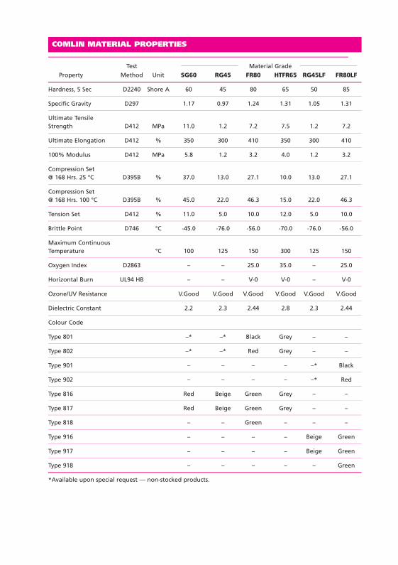
COMLIN MATERIAL PROPERTIES
Test Material GradeProperty Method Unit SG60 RG45 FR80 HTFR65 RG45LF FR80LF
Hardness, 5 Sec D2240 Shore A 60 45 80 65 50 85
Specific Gravity D297 1.17 0.97 1.24 1.31 1.05 1.31
Ultimate TensileStrength D412 MPa 11.0 1.2 7.2 7.5 1.2 7.2
Ultimate Elongation D412 % 350 300 410 350 300 410
100% Modulus D412 MPa 5.8 1.2 3.2 4.0 1.2 3.2
Compression Set@ 168 Hrs. 25 °C D395B % 37.0 13.0 27.1 10.0 13.0 27.1
Compression Set@ 168 Hrs. 100 °C D395B % 45.0 22.0 46.3 15.0 22.0 46.3
Tension Set D412 % 11.0 5.0 10.0 12.0 5.0 10.0
Brittle Point D746 °C -45.0 -76.0 -56.0 -70.0 -76.0 -56.0
Maximum ContinuousTemperature °C 100 125 150 300 125 150
Oxygen Index D2863 – – 25.0 35.0 – 25.0
Horizontal Burn UL94 HB – – V-0 V-0 – V-0
Ozone/UV Resistance V.Good V.Good V.Good V.Good V.Good V.Good
Dielectric Constant 2.2 2.3 2.44 2.8 2.3 2.44
Colour Code
Type 801 –* –* Black Grey – –
Type 802 –* –* Red Grey – –
Type 901 – – – – –* Black
Type 902 – – – – –* Red
Type 816 Red Beige Green Grey – –
Type 817 Red Beige Green Grey – –
Type 818 – – Green – – –
Type 916 – – – – Beige Green
Type 917 – – – – Beige Green
Type 918 – – – – – Green
*Available upon special request — non-stocked products.
20810 Pages 117-134.qxd:S5 Comlin Isolation 28/9/11 11:46 Page 119

DIMENSIONS (mm)PART
NUMBER THDA B C D E F G Length
801-021 21 6 37 60 20 8 30 60
801-027 27 6 43 65 20 8 32 64
801-034 34 6 50 65 20 8 28 60
801-043 43 10 69 70 25 10 19 69
801-049 49 10 75 80 25 10 26 76
801-061 61 10 87 90 25 10 30 80
801-072 72 12 98 95 25 10 25 83
801-089 89 12 115 100 25 10 22 80
801-115 115 12 141 110 25 10 19 77
801-140 140 12 166 135 25 10 31 89
801 COMLIN GRIP TYPE LINED U-BOLTFOR STAINLESS STEEL & GALVANISED PIPES -60°C TO +300°C
A
C
A/2D
B
E
F
G
ORDER BY: PART NUMBER ‘801-aaa-b-c-d’AVAILABLE IN GRADES FR80 & HTFR65.
DIMENSIONS (mm)PART
NUMBER THDA B C D E F G Length
801-168 168 16 210 180 35 15 49 128
801-219 219 16 261 200 35 15 44 123
801-245 245 16 287 210 35 15 41 120
801-273 273 16 315 225 35 15 42 121
801-324 324 16 366 250 35 15 41 120
801-356 356 16 398 265 35 15 40 119
801-407 407 16 449 300 35 15 50 129
ORDER BY: PART NUMBER ‘802-aaa-b-c-d’AVAILABLE IN GRADES FR80 & HTFR65.
DIMENSIONS (mm)PART
NUMBER THDA B C D E F G Length
802-016 16 6 32 60 20 8 32 60
802-025 25 6 41 65 20 8 33 65
802-030 30 6 46 65 20 8 30 62
802-038 38 10 64 70 25 10 21 70
802-045 45 10 71 80 25 10 28 78
802-057 57 10 83 90 25 10 32 82
802 COMLIN GRIP TYPE LINED U-BOLTFOR COPPER & CUPRO-NICKEL PIPES -60°C TO +300°C
DIMENSIONS (mm)PART
NUMBER THDA B C D E F G Length
802-076 76 12 102 100 25 10 28 86
802-089 89 12 115 110 25 10 32 90
802-108 108 12 134 120 25 10 32 90
802-159 159 16 201 165 35 15 39 118
802-219 219 16 261 200 35 15 44 123
20810 Pages 117-134.qxd:S5 Comlin Isolation 28/9/11 11:46 Page 120
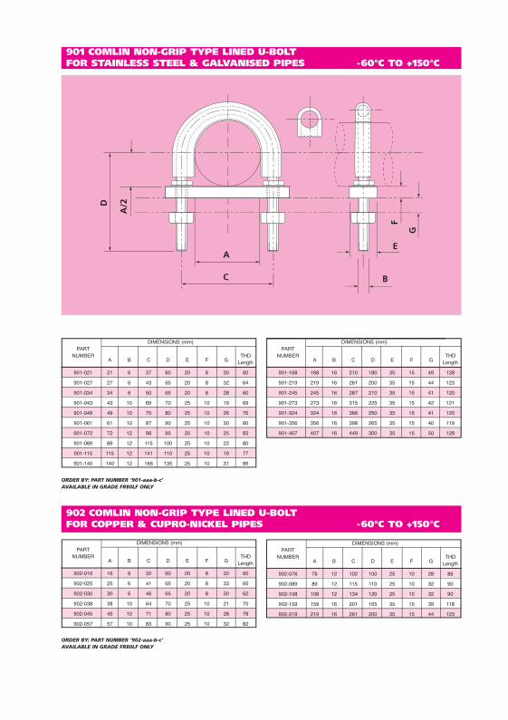
901 COMLIN NON-GRIP TYPE LINED U-BOLTFOR STAINLESS STEEL & GALVANISED PIPES -60°C TO +150°C
A
C
A/2D
B
E
F
G
DIMENSIONS (mm)PART
NUMBER THDA B C D E F G Length
901-021 21 6 37 60 20 8 30 60
901-027 27 6 43 65 20 8 32 64
901-034 34 6 50 65 20 8 28 60
901-043 43 10 69 70 25 10 19 69
901-049 49 10 75 80 25 10 26 76
901-061 61 10 87 90 25 10 30 80
901-072 72 12 98 95 25 10 25 83
901-089 89 12 115 100 25 10 22 80
901-115 115 12 141 110 25 10 19 77
901-140 140 12 166 135 25 10 31 89
ORDER BY: PART NUMBER ‘901-aaa-b-c’AVAILABLE IN GRADE FR80LF ONLY
DIMENSIONS (mm)PART
NUMBER THDA B C D E F G Length
901-168 168 16 210 180 35 15 49 128
901-219 219 16 261 200 35 15 44 123
901-245 245 16 287 210 35 15 41 120
901-273 273 16 315 225 35 15 42 121
901-324 324 16 366 250 35 15 41 120
901-356 356 16 398 265 35 15 40 119
901-407 407 16 449 300 35 15 50 129
ORDER BY: PART NUMBER ‘902-aaa-b-c’AVAILABLE IN GRADE FR80LF ONLY
DIMENSIONS (mm)PART
NUMBER THDA B C D E F G Length
902-016 16 6 32 60 20 8 32 60
902-025 25 6 41 65 20 8 33 65
902-030 30 6 46 65 20 8 30 62
902-038 38 10 64 70 25 10 21 70
902-045 45 10 71 80 25 10 28 78
902-057 57 10 83 90 25 10 32 82
902 COMLIN NON-GRIP TYPE LINED U-BOLTFOR COPPER & CUPRO-NICKEL PIPES -60°C TO +150°C
DIMENSIONS (mm)PART
NUMBER THDA B C D E F G Length
902-076 76 12 102 100 25 10 28 86
902-089 89 12 115 110 25 10 32 90
902-108 108 12 134 120 25 10 32 90
902-159 159 16 201 165 35 15 39 118
902-219 219 16 261 200 35 15 44 123
20810 Pages 117-134.qxd:S5 Comlin Isolation 28/9/11 11:46 Page 121
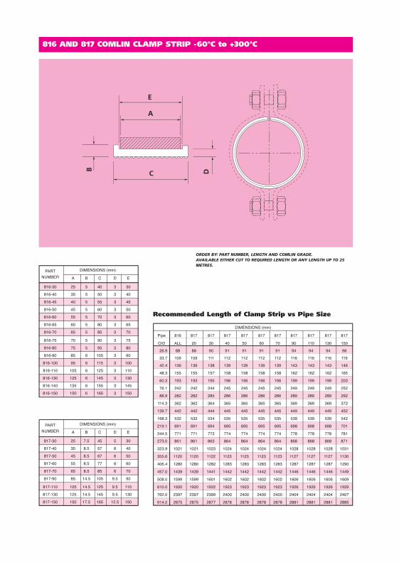
DIMENSIONS (mm)
Pipe 816 817 817 817 817 817 817 817 817 817 817
O/D ALL 20 30 40 50 60 70 90 110 130 150
26.9 88 88 90 91 91 91 91 94 94 94 98
33.7 109 109 111 112 112 112 112 116 116 116 119
42.4 136 136 138 139 139 139 139 143 143 143 146
48.3 155 155 157 158 158 158 158 162 162 162 165
60.3 193 193 195 196 196 196 196 199 199 199 203
76.1 242 242 244 245 245 245 245 249 249 249 252
88.9 282 282 285 286 286 286 286 289 289 289 292
114.3 362 362 364 365 365 365 365 369 369 369 372
139.7 442 442 444 445 445 445 445 449 449 449 452
168.3 532 532 534 535 535 535 535 539 539 539 542
219.1 691 691 694 695 695 695 695 698 698 698 701
244.5 771 771 773 774 774 774 774 778 778 778 781
273.0 861 861 863 864 864 864 864 868 868 868 871
323.9 1021 1021 1023 1024 1024 1024 1024 1028 1028 1028 1031
355.6 1120 1120 1122 1123 1123 1123 1123 1127 1127 1127 1130
406.4 1280 1280 1282 1283 1283 1283 1283 1287 1287 1287 1290
457.0 1439 1439 1441 1442 1442 1442 1442 1446 1446 1446 1449
508.0 1599 1599 1601 1602 1602 1602 1602 1606 1606 1606 1609
610.0 1920 1920 1922 1923 1923 1923 1923 1926 1926 1926 1929
762.0 2397 2397 2399 2400 2400 2400 2400 2404 2404 2404 2407
914.0 2875 2875 2877 2878 2878 2878 2878 2881 2881 2881 2885
PART DIMENSIONS (mm)
NUMBER A B C D E
816-30 25 5 40 3 30
816-40 35 5 50 3 40
816-45 40 5 55 3 45
816-50 45 5 60 3 50
816-60 55 5 70 3 60
816-65 60 5 80 3 65
816-70 65 5 85 3 70
816-75 70 5 90 3 75
816-80 75 5 95 3 80
816-90 85 6 105 3 90
816-100 95 6 115 3 100
816-110 105 6 125 3 110
816-130 125 6 145 3 130
816-140 135 6 155 3 145
816-150 150 6 165 3 150
PART DIMENSIONS (mm)
NUMBER A B C D E
817-30 25 7.5 45 5 30
817-40 35 8.5 57 6 40
817-50 45 8.5 67 6 50
817-60 55 8.5 77 6 60
817-70 65 8.5 85 6 70
817-90 85 14.5 105 9.5 90
817-110 105 14.5 125 9.5 110
817-130 125 14.5 145 9.5 130
817-150 150 17.5 165 12.5 150
816 AND 817 COMLIN CLAMP STRIP -60°C to +300°C
ORDER BY: PART NUMBER, LENGTH AND COMLIN GRADE. AVAILABLE EITHER CUT TO REQUIRED LENGTH OR ANY LENGTH UP TO 25METRES.
Recommended Length of Clamp Strip vs Pipe Size
20810 Pages 117-134.qxd:S5 Comlin Isolation 28/9/11 11:46 Page 122

DIMENSIONS (mm)
Pipe 916 917 917 917 917 917 917 917 917 917 917
O/D ALL 20 30 40 50 60 70 90 110 130 150
26.9 88 88 90 91 91 91 91 94 94 94 98
33.7 109 109 111 112 112 112 112 116 116 116 119
42.4 136 136 138 139 139 139 139 143 143 143 146
48.3 155 155 157 158 158 158 158 162 162 162 165
60.3 193 193 195 196 196 196 196 199 199 199 203
76.1 242 242 244 245 245 245 245 249 249 249 252
88.9 282 282 285 286 286 286 286 289 289 289 292
114.3 362 362 364 365 365 365 365 369 369 369 372
139.7 442 442 444 445 445 445 445 449 449 449 452
168.3 532 532 534 535 535 535 535 539 539 539 542
219.1 691 691 694 695 695 695 695 698 698 698 701
244.5 771 771 773 774 774 774 774 778 778 778 781
273.0 861 861 863 864 864 864 864 868 868 868 871
323.9 1021 1021 1023 1024 1024 1024 1024 1028 1028 1028 1031
355.6 1120 1120 1122 1123 1123 1123 1123 1127 1127 1127 1130
406.4 1280 1280 1282 1283 1283 1283 1283 1287 1287 1287 1290
457.0 1439 1439 1441 1442 1442 1442 1442 1446 1446 1446 1449
508.0 1599 1599 1601 1602 1602 1602 1602 1606 1606 1606 1609
610.0 1920 1920 1922 1923 1923 1923 1923 1926 1926 1926 1929
762.0 2397 2397 2399 2400 2400 2400 2400 2404 2404 2404 2407
914.0 2875 2875 2877 2878 2878 2878 2878 2881 2881 2881 2885
916 AND 917 COMLIN LINED CLAMP STRIP -60°C TO +150°C
ORDER BY: PART NUMBER & LENGTHAVAILABLE IN GRADE FR80LF ONLY IN ANY LENGTH UP TO 25 METRES.
Recommended Length of Clamp Strip vs Pipe Size
PART DIMENSIONS (mm)
NUMBER A B C D E
916-30 25 5 40 3 30
916-40 35 5 50 3 40
916-45 40 5 55 3 45
916-50 45 5 60 3 50
916-60 55 5 70 3 60
916-65 60 5 80 3 65
916-70 65 5 85 3 70
916-75 70 5 90 3 75
916-80 75 5 95 3 80
916-90 85 6 105 3 90
916-100 95 6 115 3 100
916-110 105 6 125 3 110
916-130 125 6 145 3 130
916-140 135 6 155 3 145
916-150 150 6 165 3 150
PART DIMENSIONS (mm)
NUMBER A B C D E
917-30 25 7.5 45 5 30
917-40 35 8.5 57 6 40
917-50 45 8.5 67 6 50
917-60 55 8.5 77 6 60
917-70 65 8.5 85 6 70
917-90 85 14.5 105 9.5 90
917-110 105 14.5 125 9.5 110
917-130 125 14.5 145 9.5 130
917-150 150 17.5 165 12.5 150
20810 Pages 117-134.qxd:S5 Comlin Isolation 28/9/11 11:46 Page 123

818 COMLIN GRIP CLAMP STRIP-60°C TO +300°C
ORDER BY: PART NUMBER, LENGTH & COMLIN GRADEAVAILABLE IN GRADES FR80 & HTFR65 IN ANY LENGTH UP TO 25 METRES.
ORDER BY: PART NUMBER & LENGTHAVAILABLE IN GRADE FR80LF ONLY IN ANY LENGTH UP TO 25 METRES.
A
C
B
3
PART NUMBER A B C
818 - 025 x 06 25 6 30
818 - 035 x 06 35 6 40
818 - 050 x 06 50 6 55
818 - 050 x 10 50 10 55
818 - 065 x 10 65 10 70
818 - 080 x 10 80 10 85
818 - 100 x 10 100 10 105
818 -100 x 20 100 20 105
918 COMLIN LINED CLAMP STRIP -60°C TO +150°C
PART NUMBER A B C
918 - 025 x 06 25 6 30
918 - 035 x 06 35 6 40
918 - 050 x 06 50 6 55
918 - 050 x 10 50 10 55
918 - 065 x 10 65 10 70
918 - 080 x 10 80 10 85
918 - 100 x 10 100 10 105
918 - 100 x 20 100 20 105
20810 Pages 117-134.qxd:S5 Comlin Isolation 28/9/11 11:46 Page 124
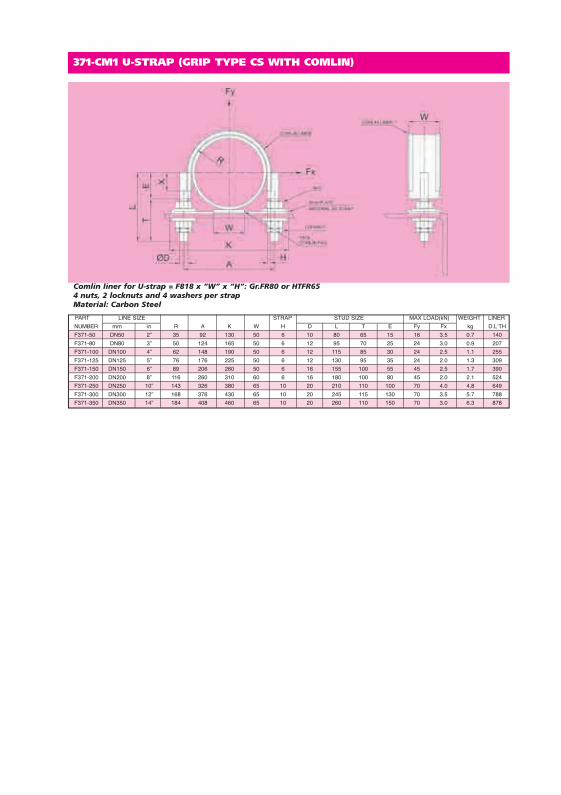
PART LINE SIZE STRAP STUD SIZE MAX LOAD(kN) WEIGHT LINER
NUMBER mm in R A K W H D L T E Fy Fx kg D.LʼTH
F371-50 DN50 2” 35 92 130 50 6 10 80 65 15 16 3.5 0.7 140
F371-80 DN80 3” 50 124 165 50 6 12 95 70 25 24 3.0 0.9 207
F371-100 DN100 4” 62 148 190 50 6 12 115 85 30 24 2.5 1.1 255
F371-125 DN125 5” 76 176 225 50 6 12 130 95 35 24 2.0 1.3 309
F371-150 DN150 6” 89 206 260 50 6 16 155 100 55 45 2.5 1.7 390
F371-200 DN200 8” 116 260 310 60 6 16 180 100 80 45 2.0 2.1 524
F371-250 DN250 10” 143 326 380 65 10 20 210 110 100 70 4.0 4.8 649
F371-300 DN300 12” 168 376 430 65 10 20 245 115 130 70 3.5 5.7 788
F371-350 DN350 14” 184 408 460 65 10 20 260 110 150 70 3.0 6.3 878
Comlin liner for U-strap = F818 x “W” x “H”: Gr.FR80 or HTFR654 nuts, 2 locknuts and 4 washers per strapMaterial: Carbon Steel
371-CM1 U-STRAP (GRIP TYPE CS WITH COMLIN)
20810 Pages 117-134.qxd:S5 Comlin Isolation 28/9/11 11:47 Page 125
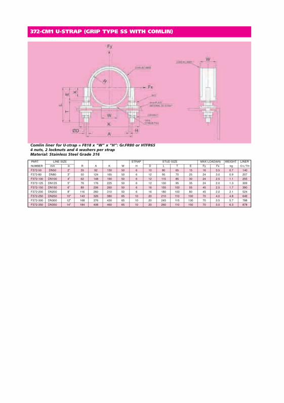
PART LINE SIZE STRAP STUD SIZE MAX LOAD(kN) WEIGHT LINER
NUMBER mm in R A K W H D L T E Fy Fx kg D.LʼTH
F372-50 DN50 2” 35 92 130 50 6 10 80 65 15 16 3.5 0.7 140
F372-80 DN80 3” 50 124 165 50 6 12 95 70 25 24 3.0 0.9 207
F372-100 DN100 4” 62 148 190 50 6 12 115 85 30 24 2.5 1.1 255
F372-125 DN125 5” 76 176 225 50 6 12 130 95 35 24 2.0 1.3 309
F372-150 DN150 6” 89 206 260 50 6 16 155 100 55 45 2.5 1.7 390
F372-200 DN200 8” 116 260 310 50 6 16 180 100 80 45 2.0 2.1 524
F372-250 DN250 10” 143 326 380 65 10 20 210 110 100 70 4.0 4.8 649
F372-300 DN300 12” 168 376 430 65 10 20 245 115 130 70 3.5 5.7 788
F372-350 DN350 14” 184 408 460 65 10 20 260 110 150 70 3.0 6.3 878
Comlin liner for U-strap = F818 x “W” x “H”: Gr.FR80 or HTFR654 nuts, 2 locknuts and 4 washers per strapMaterial: Stainless Steel Grade 316
372-CM1 U-STRAP (GRIP TYPE SS WITH COMLIN)
20810 Pages 117-134.qxd:S5 Comlin Isolation 28/9/11 11:47 Page 126
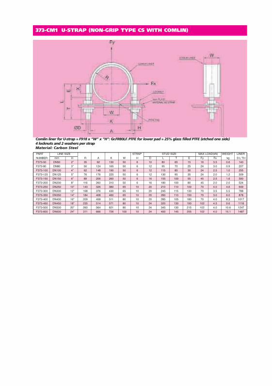
PART LINE SIZE STRAP STUD SIZE MAX LOAD(kN) WEIGHT LINER
NUMBER mm in R A K W H D L T E Fy Fx kg D.LʼTH
F373-50 DN50 2” 35 92 130 50 6 10 80 65 15 16 3.5 0.6 140
F373-80 DN80 3” 50 124 165 50 6 12 95 70 25 24 3.0 0.9 207
F373-100 DN100 4” 62 148 190 50 6 12 115 85 30 24 2.5 1.0 255
F373-125 DN125 5” 76 176 225 50 6 12 130 95 35 24 2.0 1.2 309
F373-150 DN150 6” 89 206 260 50 6 16 155 100 55 45 2.5 1.6 390
F373-200 DN200 8” 116 260 310 50 6 16 180 100 80 45 2.0 2.0 524
F373-250 DN250 10” 143 326 380 65 10 20 210 110 100 70 4.0 4.6 649
F373-300 DN300 12” 168 376 430 65 10 20 245 115 130 70 3.5 5.5 788
F373-350 DN350 14” 184 408 460 65 10 20 260 110 150 70 3.0 6.0 878
F373-400 DN400 16” 209 458 511 80 10 20 285 105 180 70 4.0 8.3 1017
F373-450 DN450 18” 235 514 571 80 10 24 320 130 190 102 4.5 9.6 1118
F373-500 DN500 20” 260 564 621 80 10 24 345 130 215 102 4.0 10.6 1247
F373-600 DN600 24” 311 666 726 100 10 24 400 145 255 102 4.0 15.1 1487
Comlin liner for U-strap = F918 x “W” x “H”: Gr.FR80LF. PTFE for lower pad = 25% glass filled PTFE (etched one side)4 locknuts and 2 washers per strapMaterial: Carbon Steel
373-CM1 U-STRAP (NON-GRIP TYPE CS WITH COMLIN)
20810 Pages 117-134.qxd:S5 Comlin Isolation 28/9/11 11:47 Page 127

PART LINE SIZE STRAP STUD SIZE MAX LOAD(kN) WEIGHT LINER
NUMBER mm in R A K W H D L T E Fy Fx kg D.LʼTH
F374-50 DN50 2” 35 92 130 50 6 10 80 65 15 16 3.5 0.6 140
F374-80 DN80 3” 50 124 165 50 6 12 95 70 25 24 3.0 0.9 207
F374-100 DN100 4” 62 148 190 50 6 12 115 85 30 24 2.5 1.0 255
F374-125 DN125 5” 76 176 225 50 6 12 130 95 35 24 2.0 1.2 309
F374-150 DN150 6” 89 206 260 50 6 16 155 100 55 45 2.5 1.6 390
F374-200 DN200 8” 116 260 310 50 6 16 180 100 80 45 2.0 2.0 524
F374-250 DN250 10” 143 326 380 65 10 20 210 110 100 70 4.0 4.6 649
F374-300 DN300 12” 168 376 430 65 10 20 245 115 130 70 3.5 5.5 788
F374-350 DN350 14” 184 408 460 65 10 20 260 110 150 70 3.0 6.0 878
F374-400 DN400 16” 209 458 511 80 10 20 285 105 180 70 4.0 8.3 1017
F374-450 DN450 18” 235 514 571 80 10 24 320 130 190 102 4.5 9.6 1118
F374-500 DN500 20” 260 564 621 80 10 24 345 130 215 102 4.0 10.6 1247
F374-600 DN600 24” 311 666 726 100 10 24 400 145 255 102 4.0 15.1 1487
Comlin liner for U-strap = F918 x “W” x “H”: Gr.FR80LF. PTFE for lower pad = 25% glass filled PTFE (etched one side)4 locknuts and 2 washers per strapMaterial: Stainless Steel Grade 316
374-CM1 U-STRAP (NON-GRIP TYPE SS WITH COMLIN)
20810 Pages 117-134.qxd:S5 Comlin Isolation 28/9/11 11:47 Page 128

TWO BOLT PIPE CLAMP WITH COMLIN MAX. TEMPERATURE 300ºC
C
E
D
B
ØA
Order by Part Number, Comlin Type and Comlin Grade e.g. PC2-CM2-100-2/817/FR80Material: Carbon Steel and Comlin. Also available in Stainless Steel.Pipe Clamps with other Load Capacities are also available.* Do not exceed the Maximum Temperature for the Grade of Comlin used.
*LOADPART NUMBER FOR PART NUMBER FOR PIPE O/D A B C D E WEIGHT CAPACITYCOMLIN TYPE COMLIN TYPE AT 300°C816, 916, 818 & 918 817 &917 mm in mm mm mm in mm mm kgf kgf
PC2-CM1-15-0 PC2-CM2-15-0 21.3 0.839 12 15 35 13/8 18 35 0.4 390PC2-CM1-20-0 PC2-CM2-20-0 26.7 1.051 12 15 40 19/16 18 35 0.4 390PC2-CM1-25-0 PC2-CM2-25-0 33.4 1.315 12 15 45 13/4 18 35 0.5 390PC2-CM1-32-0 PC2-CM2-32-0 42.2 1.661 12 15 50 115/16 18 35 0.5 390PC2-CM1-40-0 PC2-CM2-40-0 48.3 1.902 12 15 55 23/16 18 35 0.5 390PC2-CM1-50-0 PC2-CM2-50-0 60.3 2.375 12 15 60 23/8 18 35 0.6 390PC2-CM1-65-2 PC2-CM2-65-2 73 2.875 16 17 70 23/4 24 40 1.0 590PC2-CM1-80-2 PC2-CM2-80-2 88.9 3.500 16 17 80 31/8 24 40 1.1 530PC2-CM1-100-0 PC2-CM2-100-0 114.3 4.500 12 15 90 39/16 18 35 0.8 270PC2-CM1-100-2 PC2-CM2-100-2 114.3 4.500 16 17 100 315/16 24 40 1.7 740PC2-CM1-150-0 PC2-CM2-150-0 168.3 6.625 12 15 120 43/4 18 40 1.4 340PC2-CM1-150-2 PC2-CM2-150-2 168.3 6.625 16 17 125 415/16 24 40 2.1 590PC2-CM1-200-1 PC2-CM2-200-1 219.1 8.625 16 17 155 61/8 24 40 2.5 460PC2-CM1-200-2 PC2-CM2-200-2 219.1 8.625 16 17 160 65/16 24 45 3.5 790PC2-CM1-250-1 PC2-CM2-250-1 273 10.750 16 17 180 71/16 24 40 2.9 410PC2-CM1-250-3 PC2-CM2-250-3 273 10.750 20 20 195 711/16 30 60 6.9 1240PC2-CM1-300-2 PC2-CM2-300-2 323.9 12.750 16 17 210 81/4 24 45 4.6 650PC2-CM1-300-4 PC2-CM2-300-4 323.9 12.750 24 25 240 97/16 36 65 14.8 1830PC2-CM1-350-3 PC2-CM2-350-3 355.6 14.000 20 20 235 91/4 30 60 8.3 1080PC2-CM1-350-5 PC2-CM2-350-5 355.6 14.000 30 29 265 107/16 45 90 23.2 3050PC2-CM1-400-4 PC2-CM2-400-4 406.4 16.000 24 25 280 11 36 65 17.3 1830PC2-CM1-400-6 PC2-CM2-400-6 406.4 16.000 36 41 295 115/8 54 110 32.3 3810PC2-CM1-450-4 PC2-CM2-450-4 457.2 18.000 24 25 310 123/16 36 65 19.1 1830PC2-CM1-450-6 PC2-CM2-450-6 457.2 18.000 36 41 320 125/8 54 110 35.0 3810PC2-CM1-500-4 PC2-CM2-500-4 508 20.000 24 25 335 133/16 36 65 20.7 1830PC2-CM1-500-7 PC2-CM2-500-7 508 20.000 42 45 365 143/8 63 130 50.0 5470PC2-CM1-550-5 PC2-CM2-550-5 558.8 22.000 30 29 370 149/16 45 90 32.3 2920PC2-CM1-550-7 PC2-CM2-550-7 558.8 22.000 42 45 395 159/16 63 130 63.0 5470PC2-CM1-600-5 PC2-CM2-600-5 609.6 24.000 30 29 395 159/16 45 90 34.5 2660PC2-CM1-600-7 PC2-CM2-600-7 609.6 24.000 42 45 420 169/16 63 130 66.9 5470PC2-CM1-650-5 PC2-CM2-650-5 660.4 26.000 30 29 420 169/16 45 90 36.7 2530PC2-CM1-650-7 PC2-CM2-650-7 660.4 26.000 42 45 445 171/2 63 150 81.4 5470PC2-CM1-700-5 PC2-CM2-700-5 711.2 28.000 30 29 445 171/2 45 90 38.9 2420PC2-CM1-700-7 PC2-CM2-700-7 711.2 28.000 42 45 470 181/2 63 150 85.9 5470PC2-CM1-750-5 PC2-CM2-750-5 762 30.000 30 29 475 1811/16 45 110 41.1 2350PC2-CM1-750-8 PC2-CM2-750-8 762 30.000 48 52 515 201/4 72 150 112.8 7610PC2-CM1-800-5 PC2-CM2-800-5 812.8 32.000 30 29 500 1911/16 45 110 53.1 2780PC2-CM1-800-8 PC2-CM2-800-8 812.8 32.000 48 52 560 221/16 72 150 158.9 10910PC2-CM1-850-5 PC2-CM2-850-5 863.6 34.000 30 29 525 2011/16 45 110 55.8 2690PC2-CM1-850-8 PC2-CM2-850-8 863.6 34.000 48 52 590 231/4 72 150 167.2 10910PC2-CM1-900-6 PC2-CM2-900-6 914.4 36.000 36 41 570 227/16 54 110 75.6 3760PC2-CM1-900-8 PC2-CM2-900-8 914.4 36.000 48 52 615 243/16 72 150 174.6 10910PC2-CM1-950-6 PC2-CM2-950-6 965 38.000 36 41 595 237/16 54 130 79.0 3660PC2-CM1-950-8 PC2-CM2-950-8 965 38.000 48 52 640 253/16 72 150 182.0 10910PC2-CM1-1000-6 PC2-CM2-1000-6 1016 40.000 36 41 620 247/16 54 130 97.2 3810PC2-CM1-1000-8 PC2-CM2-1000-8 1016 40.000 48 52 665 263/16 72 150 189.3 10910
20810 Pages 117-134.qxd:S5 Comlin Isolation 28/9/11 11:47 Page 129
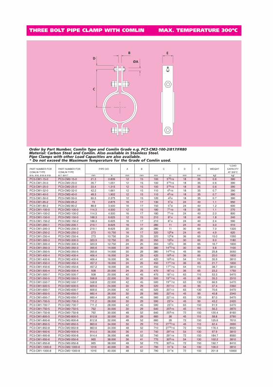
THREE BOLT PIPE CLAMP WITH COMLIN MAX. TEMPERATURE 300ºC
C
D
B
ØA
E
Order by Part Number, Comlin Type and Comlin Grade e.g. PC3-CM2-100-2/817/FR80Material: Carbon Steel and Comlin. Also available in Stainless Steel.Pipe Clamps with other Load Capacities are also available.* Do not exceed the Maximum Temperature for the Grade of Comlin used.
*LOADPART NUMBER FOR PART NUMBER FOR PIPE O/D A B C D E WEIGHT CAPACITYCOMLIN TYPE COMLIN TYPE AT 300°C816, 916, 818 & 918 817 &917 mm in mm mm mm in mm mm kgf kgf
PC3-CM1-15-0 PC3-CM2-15-0 21.3 0.839 12 15 100 315/16 18 35 0.6 390PC3-CM1-20-0 PC3-CM2-20-0 26.7 1.051 12 15 100 315/16 18 35 0.6 390PC3-CM1-25-0 PC3-CM2-25-0 33.4 1.315 12 15 100 315/16 18 35 0.6 390PC3-CM1-32-0 PC3-CM2-32-0 42.2 1.661 12 15 110 45/16 18 35 0.7 390PC3-CM1-40-0 PC3-CM2-40-0 48.3 1.902 12 15 110 45/16 18 35 0.7 390PC3-CM1-50-0 PC3-CM2-50-0 60.3 2.375 12 15 120 43/4 18 35 0.7 390PC3-CM1-65-2 PC3-CM2-65-2 73 2.875 16 17 130 51/8 24 40 1.1 650PC3-CM1-80-2 PC3-CM2-80-2 88.9 3.500 16 17 150 57/8 24 40 1.2 600PC3-CM1-100-0 PC3-CM2-100-0 114.3 4.500 12 15 180 71/16 18 35 1.1 270PC3-CM1-100-2 PC3-CM2-100-2 114.3 4.500 16 17 180 71/16 24 40 2.0 800PC3-CM1-150-0 PC3-CM2-150-0 168.3 6.625 12 15 210 81/4 18 40 1.8 340PC3-CM1-150-2 PC3-CM2-150-2 168.3 6.625 16 17 210 81/4 24 40 2.4 590PC3-CM1-200-1 PC3-CM2-200-1 219.1 8.625 16 17 280 11 24 40 3.0 510PC3-CM1-200-3 PC3-CM2-200-3 219.1 8.625 20 20 280 11 30 60 7.0 1320PC3-CM1-250-2 PC3-CM2-250-2 273 10.750 16 17 320 125/8 24 45 4.9 620PC3-CM1-250-4 PC3-CM2-250-4 273 10.750 24 25 320 125/8 36 65 15.0 1590PC3-CM1-300-3 PC3-CM2-300-3 323.9 12.750 20 20 350 133/4 30 60 9.0 1180PC3-CM1-300-4 PC3-CM2-300-4 323.9 12.750 24 25 350 133/4 36 65 16.7 1830PC3-CM1-350-3 PC3-CM2-350-3 355.6 14.000 20 20 380 1415/16 30 60 9.8 1100PC3-CM1-350-5 PC3-CM2-350-5 355.6 14.000 30 29 380 1415/16 45 90 25.8 3050PC3-CM1-400-4 PC3-CM2-400-4 406.4 16.000 24 25 420 169/16 36 65 20.0 1830PC3-CM1-400-6 PC3-CM2-400-6 406.4 16.000 36 41 420 169/16 54 110 35.9 3810PC3-CM1-450-4 PC3-CM2-450-4 457.2 18.000 24 25 450 1711/16 36 65 21.7 1830PC3-CM1-450-6 PC3-CM2-450-6 457.2 18.000 36 41 450 1711/16 54 110 38.7 3810PC3-CM1-500-4 PC3-CM2-500-4 508 20.000 24 25 470 181/12 36 65 23.2 1750PC3-CM1-500-7 PC3-CM2-500-7 508 20.000 42 45 470 181/12 63 110 53.3 5470PC3-CM1-550-5 PC3-CM2-550-5 558.8 22.000 30 29 500 1911/16 45 90 35.3 2510PC3-CM1-550-7 PC3-CM2-550-7 558.8 22.000 42 45 500 1911/16 63 130 66.9 5470PC3-CM1-600-5 PC3-CM2-600-5 609.6 24.000 30 29 520 201/12 45 90 37.4 2360PC3-CM1-600-7 PC3-CM2-600-7 609.6 24.000 42 45 520 201/12 63 130 70.6 5470PC3-CM1-650-5 PC3-CM2-650-5 660.4 26.000 30 29 560 221/16 45 90 40.8 2340PC3-CM1-650-7 PC3-CM2-650-7 660.4 26.000 42 45 560 221/16 63 130 87.0 5470PC3-CM1-700-5 PC3-CM2-700-5 711.2 28.000 30 29 590 231/4 45 90 43.2 2420PC3-CM1-700-7 PC3-CM2-700-7 711.2 28.000 42 45 590 231/4 63 150 91.9 5470PC3-CM1-750-5 PC3-CM2-750-5 762 30.000 30 29 640 253/16 45 110 56.3 2870PC3-CM1-750-8 PC3-CM2-750-8 762 30.000 48 52 640 253/16 72 150 120.4 8160PC3-CM1-800-5 PC3-CM2-800-5 812.8 32.000 30 29 660 26 45 110 58.8 2790PC3-CM1-800-8 PC3-CM2-800-8 812.8 32.000 48 52 660 26 72 150 125.6 7610PC3-CM1-850-5 PC3-CM2-850-5 863.6 34.000 30 29 710 2715/16 45 110 62.4 2690PC3-CM1-850-8 PC3-CM2-850-8 863.6 34.000 48 52 710 2715/16 72 150 176.4 8920PC3-CM1-900-6 PC3-CM2-900-6 914.4 36.000 36 41 740 291/18 54 130 97.9 3810PC3-CM1-900-8 PC3-CM2-900-8 914.4 36.000 48 52 740 291/18 72 150 184.7 8560PC3-CM1-950-6 PC3-CM2-950-6 965 38.000 36 41 770 305/16 54 130 102.2 3810PC3-CM1-950-8 PC3-CM2-950-8 965 38.000 48 52 770 305/16 72 150 192.7 8410PC3-CM1-1000-6 PC3-CM2-1000-6 1016 40.000 36 41 790 311/8 54 130 106.0 3810PC3-CM1-1000-8 PC3-CM2-1000-8 1016 40.000 48 52 790 311/8 72 150 201.8 10000
20810 Pages 117-134.qxd:S5 Comlin Isolation 28/9/11 11:47 Page 130

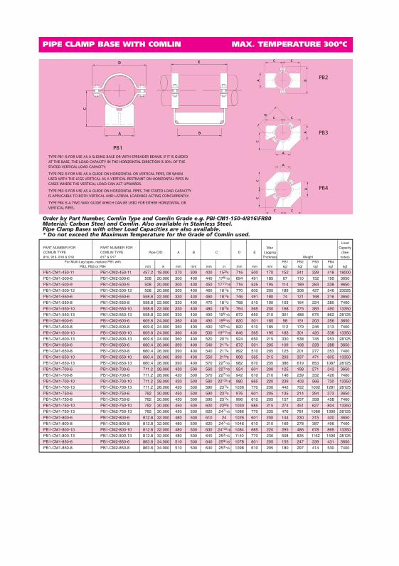
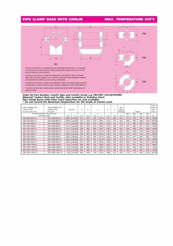
PIPE CLAMP BASE WITH COMLIN MAX. TEMPERATURE 300ºC
D
A
C
E
B
C
A D
C
C C
A
C
A
D
A
CC
CC
A
Order by Part Number, Comlin Type and Comlin Grade e.g. PB1-CM1-150-4/816/FR80Material: Carbon Steel and Comlin. Also available in Stainless Steel.Pipe Clamp Bases with other Load Capacities are also available.* Do not exceed the Maximum Temperature for the Grade of Comlin used.
LoadPART NUMBER FOR PART NUMBER FOR Max CapacityCOMLIN TYPE COMLIN TYPE Pipe O/D A B C D E Lagging (See816, 916, 818 & 918 817 & 917 . Thickness Weight notes)
For Multi-Leg types, replace PB1 with PB1 PB2 PB3 PB4PB2, PB3 or PB4 mm in mm mm mm in mm mm mm kgf kgf kgf kgf kgf
PB1-CM1-15-1 PB1-CM2-15-1 21.3 0.839 50 150 90 39/16 106 185 75 1.8 3.0 4.2 5.4 360
PB1-CM1-20-1 PB1-CM2-20-1 26.7 1.051 50 150 90 39/16 110 185 75 1.8 3.0 4.2 5.4 360
PB1-CM1-25-1 PB1-CM2-25-1 33.4 1.315 50 150 90 39/16 120 185 70 1.9 3.1 4.3 5.4 360
PB1-CM1-32-1 PB1-CM2-32-1 42.2 1.661 60 150 100 315/16 130 185 75 2.3 3.7 5.2 6.7 360
PB1-CM1-40-1 PB1-CM2-40-1 48.3 1.902 60 150 100 315/16 138 185 75 2.3 3.8 5.2 6.7 360
PB1-CM1-50-2 PB1-CM2-50-2 60.3 2.375 70 150 110 45/16 150 203 75 2.7 4.4 6.2 7.9 530
PB1-CM1-65-2 PB1-CM2-65-2 73 2.875 70 200 110 45/16 166 253 70 3.1 5.2 7.2 9.3 530
PB1-CM1-80-2 PB1-CM2-80-2 88.9 3.500 100 200 160 65/16 182 253 115 4.6 7.9 11 15 530
PB1-CM1-90-2 PB1-CM2-90-2 101.6 4.000 100 200 160 65/16 196 253 105 4.7 8.0 11 15 530
PB1-CM1-100-3 PB1-CM2-100-3 114.3 4.500 100 200 170 611/16 208 253 110 4.8 8.2 12 15 1010
PB1-CM1-125-3 PB1-CM2-125-3 141.3 5.563 110 200 180 71/16 236 253 105 5.4 9.2 13 17 1010
PB1-CM1-150-4 PB1-CM2-150-4 168.3 6.625 120 200 200 77/8 278 264 115 9.3 15 21 27 1580
PB1-CM1-175-5 PB1-CM2-175-5 193.7 7.625 140 250 240 97/16 302 314 140 12 20 29 37 2280
PB1-CM1-200-3 PB1-CM2-200-3 219.1 8.625 150 250 250 913/16 320 308 140 9.8 16 23 29 1010
PB1-CM1-200-6 PB1-CM2-200-6 219.1 8.625 150 250 250 913/16 364 346 140 24 38 52 65 3650
PB1-CM1-225-3 PB1-CM2-225-3 244.5 9.625 160 250 260 101/4 346 308 135 11 18 25 32 1010
PB1-CM1-225-6 PB1-CM2-225-6 244.5 9.625 160 250 270 105/8 392 346 145 26 41 57 72 3650
PB1-CM1-250-4 PB1-CM2-250-4 273 10.750 170 250 280 11 384 314 140 16 26 36 47 1580
PB1-CM1-250-7 PB1-CM2-250-7 273 10.750 170 250 280 11 420 346 140 28 45 61 77 5340
PB1-CM1-300-4 PB1-CM2-300-4 323.9 12.750 190 300 320 125/8 446 369 155 22 35 49 62 1580
PB1-CM1-300-6 PB1-CM2-300-6 323.9 12.750 190 300 320 125/8 474 396 155 35 56 76 97 3650
PB1-CM1-300-8 PB1-CM2-300-8 323.9 12.750 190 300 320 125/8 526 410 155 54 80 106 133 7400
PB1-CM1-350-6 PB1-CM2-350-6 355.6 14.000 210 300 340 133/8 506 396 160 39 62 86 109 3650
PB1-CM1-350-7 PB1-CM2-350-7 355.6 14.000 210 300 340 133/8 506 396 160 39 62 86 109 5340
PB1-CM1-350-9 PB1-CM2-350-9 355.6 14.000 210 300 340 133/8 560 425 160 70 111 152 193 9650
PB1-CM1-400-6 PB1-CM2-400-6 406.4 16.000 240 300 360 143/16 570 391 155 47 74 101 128 3650
PB1-CM1-400-8 PB1-CM2-400-8 406.4 16.000 240 300 360 143/16 610 410 155 67 101 136 170 7400
PB1-CM1-400-10 PB1-CM2-400-10 406.4 16.000 240 300 370 149/16 638 465 165 109 171 233 295 13350
PB1-CM1-450-6 PB1-CM2-450-6 457.2 18.000 270 300 390 153/8 624 391 160 53 85 116 147 3650
PB1-CM1-450-9 PB1-CM2-450-9 457.2 18.000 270 300 390 153/8 664 425 160 91 145 200 255 9650
PB2
PB3
PB4
PB1
TYPE PB1 IS FOR USE AS A SLIDING BASE OR WITH SPREADER BEAMS. IF IT IS GUIDEDAT THE BASE, THE LOAD CAPACITY IN THE HORIZONTAL DIRECTION IS 30% OF THESTATED VERTICAL LOAD CAPACITY.
TYPE PB2 IS FOR USE AS A GUIDE ON HORIZONTAL OR VERTICAL PIPES, OR WHENUSED WITH THE LEGS VERTICAL AS A VERTICAL RESTRAINT ON HORIZONTAL PIPES INCASES WHERE THE VERTICAL LOAD CAN ACT UPWARDS.
TYPE PB3 IS FOR USE AS A GUIDE ON HORIZONTAL PIPES. THE STATED LOAD CAPACITYIS APPLICABLE TO BOTH VERTICAL AND LATERAL LOADINGS ACTING CONCURRENTLY.
TYPE PB4 IS A TWO WAY GUIDE WHICH CAN BE USED FOR EITHER HORIZONTAL ORVERTICAL PIPES.
20810 Pages 117-134.qxd:S5 Comlin Isolation 28/9/11 11:48 Page 131
PIPE CLAMP BASE WITH COMLIN MAX. TEMPERATURE 300ºC
D
A
C
E
B
C
A D
C
C C
A
C
A
D
A
CC
CC
A
Order by Part Number, Comlin Type and Comlin Grade e.g. PBI-CM1-150-4/816/FR80Material: Carbon Steel and Comlin. Also available in Stainless Steel.Pipe Clamp Bases with other Load Capacities are also available.* Do not exceed the Maximum Temperature for the Grade of Comlin used.
LoadPART NUMBER FOR PART NUMBER FOR Max CapacityCOMLIN TYPE COMLIN TYPE Pipe O/D A B C D E Lagging (See816, 916, 818 & 918 817 & 917 . Thickness Weight notes)
For Multi-Leg types, replace PB1 with PB1 PB2 PB3 PB4PB2, PB3 or PB4 mm in mm mm mm in mm mm mm kgf kgf kgf kgf kgf
PB1-CM1-450-11 PB1-CM2-450-11 457.2 18.000 270 300 400 153/4 716 500 170 152 241 329 418 18000
PB1-CM1-500-6 PB1-CM2-500-6 508 20.000 300 400 440 175/16 694 491 185 67 110 152 195 3650
PB1-CM1-500-9 PB1-CM2-500-9 508 20.000 300 400 450 1711/16 716 525 195 114 189 263 338 9650
PB1-CM1-500-12 PB1-CM2-500-12 508 20.000 300 400 460 181/8 770 600 205 189 308 427 546 23025
PB1-CM1-550-6 PB1-CM2-550-6 558.8 22.000 330 400 460 181/8 746 491 180 74 121 168 216 3650
PB1-CM1-550-8 PB1-CM2-550-8 558.8 22.000 330 400 470 181/2 768 510 190 103 164 224 285 7400
PB1-CM1-550-10 PB1-CM2-550-10 558.8 22.000 330 400 480 187/8 794 565 200 168 275 383 490 13350
PB1-CM1-550-13 PB1-CM2-550-13 558.8 22.000 330 400 490 195/16 872 650 210 301 488 675 862 28125
PB1-CM1-600-6 PB1-CM2-600-6 609.6 24.000 360 400 490 195/16 820 501 185 98 151 203 256 3650
PB1-CM1-600-8 PB1-CM2-600-8 609.6 24.000 360 400 490 195/16 820 510 185 112 179 246 313 7400
PB1-CM1-600-10 PB1-CM2-600-10 609.6 24.000 360 400 500 1911/16 846 565 195 183 301 420 538 13350
PB1-CM1-600-13 PB1-CM2-600-13 609.6 24.000 360 400 520 201/2 924 650 215 330 538 745 953 28125
PB1-CM1-650-6 PB1-CM2-650-6 660.4 26.000 390 400 540 211/4 872 501 205 109 168 228 288 3650
PB1-CM1-650-8 PB1-CM2-650-8 660.4 26.000 390 400 540 211/4 892 510 205 125 201 277 353 7400
PB1-CM1-650-10 PB1-CM2-650-10 660.4 26.000 390 400 550 215/8 898 565 215 203 337 471 605 13350
PB1-CM1-650-13 PB1-CM2-650-13 660.4 26.000 390 400 570 227/16 982 670 235 386 619 853 1087 28125
PB1-CM1-700-6 PB1-CM2-700-6 711.2 28.000 420 500 560 221/16 924 601 200 125 198 271 343 3650
PB1-CM1-700-8 PB1-CM2-700-8 711.2 28.000 420 500 570 227/16 942 610 210 146 239 332 426 7400
PB1-CM1-700-10 PB1-CM2-700-10 711.2 28.000 420 500 580 2213/16 980 665 220 239 403 566 730 13350
PB1-CM1-700-13 PB1-CM2-700-13 711.2 28.000 420 500 590 231/4 1036 770 230 442 722 1002 1281 28125
PB1-CM1-750-6 PB1-CM2-750-6 762 30.000 450 500 590 231/4 976 601 205 135 214 294 373 3650
PB1-CM1-750-8 PB1-CM2-750-8 762 30.000 450 500 590 231/4 996 610 205 157 257 358 458 7400
PB1-CM1-750-10 PB1-CM2-750-10 762 30.000 450 500 600 235/8 1030 685 215 274 451 627 804 13350
PB1-CM1-750-13 PB1-CM2-750-13 762 30.000 450 500 620 247/16 1086 770 235 476 781 1086 1390 28125
PB1-CM1-800-6 PB1-CM2-800-6 812.8 32.000 480 500 610 24 1026 601 200 144 230 315 400 3650
PB1-CM1-800-8 PB1-CM2-800-8 812.8 32.000 480 500 620 247/16 1046 610 210 169 278 387 496 7400
PB1-CM1-800-10 PB1-CM2-800-10 812.8 32.000 480 500 630 2413/16 1084 685 220 295 486 678 869 13350
PB1-CM1-800-13 PB1-CM2-800-13 812.8 32.000 480 500 640 253/16 1140 770 230 508 835 1162 1490 28125
PB1-CM1-850-6 PB1-CM2-850-6 863.6 34.000 510 500 640 253/16 1078 601 205 155 247 339 431 3650
PB1-CM1-850-8 PB1-CM2-850-8 863.6 34.000 510 500 640 253/16 1098 610 205 180 297 414 530 7400
PB2
PB3
PB4
PB1
TYPE PB1 IS FOR USE AS A SLIDING BASE OR WITH SPREADER BEAMS. IF IT IS GUIDEDAT THE BASE, THE LOAD CAPACITY IN THE HORIZONTAL DIRECTION IS 30% OF THESTATED VERTICAL LOAD CAPACITY.
TYPE PB2 IS FOR USE AS A GUIDE ON HORIZONTAL OR VERTICAL PIPES, OR WHENUSED WITH THE LEGS VERTICAL AS A VERTICAL RESTRAINT ON HORIZONTAL PIPES INCASES WHERE THE VERTICAL LOAD CAN ACT UPWARDS.
TYPE PB3 IS FOR USE AS A GUIDE ON HORIZONTAL PIPES. THE STATED LOAD CAPACITYIS APPLICABLE TO BOTH VERTICAL AND LATERAL LOADINGS ACTING CONCURRENTLY.
TYPE PB4 IS A TWO WAY GUIDE WHICH CAN BE USED FOR EITHER HORIZONTAL ORVERTICAL PIPES.
20810 Pages 117-134.qxd:S5 Comlin Isolation 28/9/11 11:48 Page 132
PIPE CLAMP BASE WITH COMLIN MAX. TEMPERATURE 300ºC
D
A
C
E
B
C
A D
C
C C
A
C
A
D
A
CC
CC
A
Order by Part Number, Comlin Type and Comlin Grade e.g. PBI-CM1-150-4/816/FR80Material: Carbon Steel and Comlin. Also available in Stainless Steel.Pipe Clamp Bases with other Load Capacities are also available.* Do not exceed the Maximum Temperature for the Grade of Comlin used.
LoadPART NUMBER FOR PART NUMBER FOR Max CapacityCOMLIN TYPE COMLIN TYPE Pipe O/D A B C D E Lagging (See816, 916, 818 & 918 817 & 917 . Thickness Weight notes)
For Multi-Leg types, replace PB1 with PB1 PB2 PB3 PB4PB2, PB3 or PB4 mm in mm mm mm in mm mm mm kgf kgf kgf kgf kgf
PB1-CM1-850-10 PB1-CM2-850-10 863.6 34.000 510 500 650 259/16 1134 685 215 314 519 724 929 13350
PB1-CM1-850-13 PB1-CM2-850-13 863.6 34.000 510 500 670 263/8 1212 770 235 583 935 1288 1640 28125
PB1-CM1-900-6 PB1-CM2-900-6 914.4 36.000 540 600 670 263/8 1128 701 210 175 285 394 504 3650
PB1-CM1-900-8 PB1-CM2-900-8 914.4 36.000 540 600 670 263/8 1156 735 210 231 369 507 646 7400
PB1-CM1-900-10 PB1-CM2-900-10 914.4 36.000 540 600 680 263/4 1186 785 220 356 598 840 1082 13350
PB1-CM1-900-13 PB1-CM2-900-13 914.4 36.000 540 600 690 273/16 1294 870 230 655 1065 1474 1884 28125
PB1-CM1-950-6 PB1-CM2-950-6 965.2 38.000 570 600 690 273/16 1182 701 205 185 302 418 535 3650
PB1-CM1-950-8 PB1-CM2-950-8 965.2 38.000 570 600 690 273/16 1206 735 205 244 391 538 685 7400
PB1-CM1-950-10 PB1-CM2-950-10 965.2 38.000 570 600 700 279/16 1236 785 215 377 634 891 1148 13350
PB1-CM1-950-13 PB1-CM2-950-13 965.2 38.000 570 600 720 283/8 1346 870 235 696 1134 1573 2011 28125
PB1-CM1-1000-6 PB1-CM2-1000-6 1016 40.000 600 600 720 283/8 1234 701 210 197 321 446 570 3650
PB1-CM1-1000-8 PB1-CM2-1000-8 1016 40.000 600 600 720 283/8 1260 735 210 259 416 573 730 7400
PB1-CM1-1000-10 PB1-CM2-1000-10 1016 40.000 600 600 730 283/4 1312 785 220 432 706 980 1254 13350
PB1-CM1-1000-13 PB1-CM2-1000-13 1016 40.000 600 600 740 291/8 1398 870 230 733 1197 1661 2125 28125
PB2
PB3
PB4
PB1
TYPE PB1 IS FOR USE AS A SLIDING BASE OR WITH SPREADER BEAMS. IF IT IS GUIDEDAT THE BASE, THE LOAD CAPACITY IN THE HORIZONTAL DIRECTION IS 30% OF THESTATED VERTICAL LOAD CAPACITY.
TYPE PB2 IS FOR USE AS A GUIDE ON HORIZONTAL OR VERTICAL PIPES, OR WHENUSED WITH THE LEGS VERTICAL AS A VERTICAL RESTRAINT ON HORIZONTAL PIPES INCASES WHERE THE VERTICAL LOAD CAN ACT UPWARDS.
TYPE PB3 IS FOR USE AS A GUIDE ON HORIZONTAL PIPES. THE STATED LOAD CAPACITYIS APPLICABLE TO BOTH VERTICAL AND LATERAL LOADINGS ACTING CONCURRENTLY.
TYPE PB4 IS A TWO WAY GUIDE WHICH CAN BE USED FOR EITHER HORIZONTAL ORVERTICAL PIPES.
20810 Pages 117-134.qxd:S5 Comlin Isolation 28/9/11 11:48 Page 133