combustion of pakistani lignite (〰ごhar coal)〰〠in a pilot...
TRANSCRIPT
This is a repository copy of Combustion of Pakistani lignite (Thar coal) in a pilot-scale pulverized fuel down-fired combustion test facility.
White Rose Research Online URL for this paper:http://eprints.whiterose.ac.uk/78170/
Article:
Daood, SS, Javed, MT, Rizvi, AH et al. (1 more author) (2014) Combustion of Pakistani lignite (Thar coal) in a pilot-scale pulverized fuel down-fired combustion test facility. Energyand Fuels, 28 (2). 1541 - 1547. ISSN 0887-0624
https://doi.org/10.1021/ef402362t
[email protected]://eprints.whiterose.ac.uk/
Reuse
Unless indicated otherwise, fulltext items are protected by copyright with all rights reserved. The copyright exception in section 29 of the Copyright, Designs and Patents Act 1988 allows the making of a single copy solely for the purpose of non-commercial research or private study within the limits of fair dealing. The publisher or other rights-holder may allow further reproduction and re-use of this version - refer to the White Rose Research Online record for this item. Where records identify the publisher as the copyright holder, users can verify any specific terms of use on the publisher’s website.
Takedown
If you consider content in White Rose Research Online to be in breach of UK law, please notify us by emailing [email protected] including the URL of the record and the reason for the withdrawal request.

promoting access to White Rose research papers
White Rose Research Online [email protected]
Universities of Leeds, Sheffield and York http://eprints.whiterose.ac.uk/
This is an author produced version of a paper published in Energy and Fuels. White Rose Research Online URL for this paper: http://eprints.whiterose.ac.uk/78170/
Paper: Daood, SS, Javed, MT, Rizvi, AH and Nimmo, W (2014) Combustion of Pakistani lignite (Thar coal) in a pilot-scale pulverized fuel down-fired combustion test facility. Energy and Fuels, 28 (2). 1541 - 1547. http://dx.doi.org/10.1021/ef402362t

1
Combustion of Pakistani Lignite (Tharparkar coal) in a pilot scale pulverised fuel1
down fired combustion test facility2
S. S. Daood1, M.T. Javed2* , A.H. Rizvi1†, W.Nimmo13
1Energy Technology and Innovation Initiative,University of Leeds, LS2 9JT, UK42Department of Chemical Engineering, Pakistan Institute of Engineering and AppliedSciences, Nilore,5Islamabad, Pakistan6
7†Presently at ICE&T, Punjab University, Lahore8*Corresponding author: Currently at ETII, University of Leeds, UK, Email: [email protected]
10
Abstract11
In this study, Pakistan’s first and foremost pilot scale combustion test results of Tharparkar12
Lignite Block-8 have been reported. The reported data will be an addition to the existing13
literatureon lignite firing testing. In this paper NO, COand CO2 measurementswere recorded at14
different axial locations in a down-fired combustion test facilityfor 2s, 2.3s and 2.6s of primary15
combustion zone residence times in a 4 meter long down-fired pulverised fuel furnace. The16
overall NOx and SO2 emissions have also been reported for un-staged and air-staged17
combustion conditions. The reported data (emissions and carbon burnouts) is for fuel to air18
stoichiometric ratios of 0.9, 1.01 and 1.16 near the burner zone. The fly ash sample were19
analysed and the percentage of iron oxide was found in the range of 18-21% whereas the20
percentage of alumina concentration was in the range of 14-16% for varying stoichiometric21
ratios. Furthermore, slagging and fouling analysishas also been carried out on the collected ash22
samplesduring testing.23
Key Words:24
Pakistani Lignite Coal; Emissions; Residence time; Stoichiometric ratios;Carbon burnout;25
Slagging and fouling indices26
1. Introduction27
Both developed and developing countries have been exploiting vital lignite coal resources for28
power generation. In recent years, countries such as Germany, Poland, Turkey, Serbia, Czech29
2
Republic and Greece have increased their lignite production to about 440 million1
tonnes1.Global lignite coal productionhas reached 1.0 billion tonnes and still has massive2
potential for growth2. Pakistan's lignite coal reserve of 176 billion tonnes has an electrical3
potential equivalent of 100,000MW3. Thiswould enable the mitigation of the present electricity4
shortfall and also enable the country to meet any electricity demand in the future. In order to5
attract investment in coal fired power plant the GOP drafted a new set of incentives which,6
offer attractionto investors as well as keep consumer prices within affordable limits. Keeping in7
viewthese objectives, the Policy for Power Generation 2002 was formulated so as to offer8
maximumincentives and assurance to investors. In the Power Policy 2002, the main emphasis9
was on the development of power projects based on indigenous fuel resources, especially coal10
andrenewables4.11
Co-firing of firewood and lignite has been proven to exhibit acceptable temperatures,12
combustion efficiency and low emissions at low (50kW) to high (150kW) thermal13
outputs5.Similarly, lignite combustion resulted in stable operation with remarkably low NO14
emission levels with stoichiometric conditions around 0.96. The concept of ignite co-firingat a15
10%biomass Cynara cardunculus (cardoon) thermal share for a 330 MWe pulverized fuel plant16
in Northern Greece is investigated.In most co-firing cases, CFDresults indicated that the17
substitution of lignite with biomass has minimal impact on the plant operationalparameters as18
well as has the potential for NOx reductions7. It is also worth mentioning that before practical19
use, lignite coal has to be dried to reduce inherent moisture. Out of available technologiesWTA20
(waste heat utilization) technology developed by RWEPower can technically and economically21
issuitable for lignite-based electricity generation8.22
In Pakistan there are discussions and plans for co-firing of indigenous coal specially Thar lignite23
with imported or locally sourced biomass. Keeping in view the future need of power plants in24
Pakistan a series of tests have been performed on a 50kWth combustion test facility (CTF)in25
order to understand the combustion characterization of PakistaniThar lignite.26
The present study expands the main combustion product concentrations (CO,O2,NOx, SO2, LOI)27
data bank for lignite coals; especially in terms of scarcely reported pilot scale combustion trials28

3
on Pakistan’s Tharparkarlignite coal. This reported data would support the research and1
development phase for establishing new lignite based power plants to overcome the energy2
crises in Pakistan.3
2. Experimental Setup4
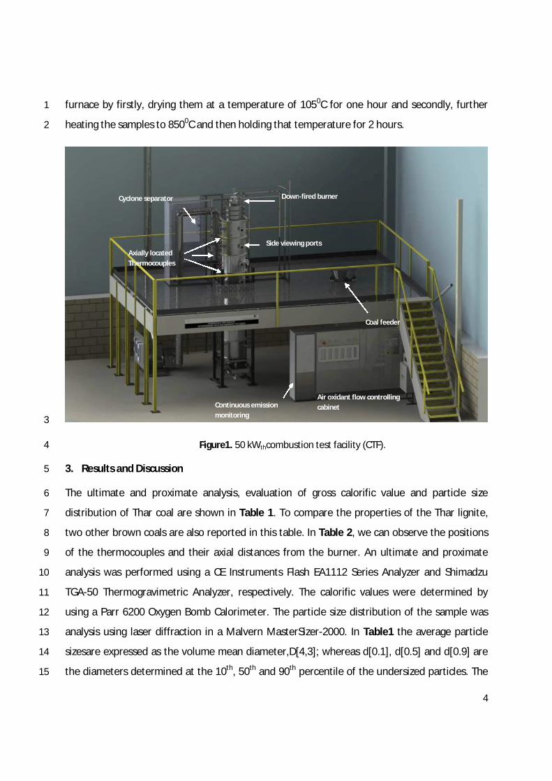
The schematic combustion test facility (CTF) comprising a down-fired pulverised coal fired5
furnace 4min length with an internal diameter of 400mm is shown in Figure 1. The burner was6
operated at an input feed rate of approximately 10.5 kg/hr of Pakistani lignite resulting in a net7
thermal input of about 50 kWth. The actual combustion test facility is designed to be operated8
at 100kWth but due to the limited availability of the coal (especially sourced via bore drilling9
after travelling nearly 960 miles) resulted experiments to be performed at lesser heat input rate10
of 50kWth. Hence lesser coal sufficient to give 50kWth input was fed in a 100kWth combustion11
test facility. The major flue gasspeciesCO2, O2, NOx, and COwere measured at the furnace exit.12
Gas samples were constantly drawn through water cooled stainless-steel probe to the gas13
sampling system so that the correct combustion conditions could be set in the furnace. The14
extracted flue gas from the probe was transferred via Poly Tetra Fluoro Ethylene (PTFE) tubing15
through a series of filters and water traps for cleaning and drying purposes. The flue gas was16
then cooled to 20C(which isa requirement for safe operation of the gasanalysers) by passing it17
through a chiller. The filters were frequently replaced and the water traps were regularly18
cleaned to prevent any blockage in the gas sampling system. The flue gas was passed through a19
manifold that directed the sample gas to different gas analysers. To prevent any blockages20
during operation, the gas sampling probe was regularly purged using a compressed nitrogen21
supplywhich was connected to the sampling probe (utilized for drawing in flue gas from the22
furnace). O2, CO2, CO, NO (NOx) and SO2emissions were monitored in real-time by gas23
analysersand temperatures down the furnace were monitored and all data was logged on a PC24
in real-time asall the testswere carried out.25
Flyash solidswere collected in a fly ash catchpot connected to a cyclone separator. The samples26
and emissions were collected and measured, respectively, after attaining steady state27
conditions for each test. Fly ash samples were analysed for loss on ignition (LOI) in a muffle28
4
furnace by firstly, drying them at a temperature of 1050C for one hour and secondly, further1
heating the samples to 8500Cand then holding that temperature for 2 hours.2
3
Figure1. 50 kWthcombustion test facility (CTF).4
3. Resultsand Discussion5
The ultimate and proximate analysis, evaluation of gross calorific value and particle size6
distribution of Thar coal are shown in Table 1. To compare the properties of the Thar lignite,7
two other brown coals are also reported in this table. In Table 2, we can observe the positions8
of the thermocouples and their axial distances from the burner. An ultimate and proximate9
analysis was performed using a CE Instruments Flash EA1112 Series Analyzer and Shimadzu10
TGA-50 Thermogravimetric Analyzer, respectively. The calorific values were determined by11
using a Parr 6200 Oxygen Bomb Calorimeter. The particle size distribution of the sample was12
analysis using laser diffraction in a Malvern MasterSizer-2000. In Table1 the average particle13
sizesare expressed as the volume mean diameter,D[4,3]; whereas d[0.1], d[0.5] and d[0.9] are14
the diameters determined at the 10th, 50th and 90th percentile of the undersized particles. The15
Air oxidant flow controllingcabinet
Coal feeder
Continuousemissionmonitoring
Down-fired burner
Side viewingports
Cyclone separator
Axially locatedThermocouples

5
particle size analysisshows that the 90%of the coal sample is less than 250 µm, which fulfil the1
design requirement of the CTF.2
Table 1. An ultimate, proximate analysisand particle size distribution of Tharparkar lignite coal along3with some reference valuesof brown coal.4
aas received basis except as denoted in table; b calculated by difference; FC= fixed carbon;5
VM= volatile matter; GCV= gross calorificvalue; D[4,3]=volume mean diameter; d[0.1],6
d[0.5] and d[0.9] are the percentile diameters determined at the 10th, 50th and 90th7
percentile of the undersized particles, cNet Calorific value (the values for ultimate analysis8
are dry ash free basis.9
Table 2. Vertical positionsof thermocouplesand samplingports.10
Fuel Ultimate Analysisa Proximate Analysisa GCVa
(MJ/kg)Moisturea
(%)
C(%)
H(%)
Ob
(%)N
(%)S
(%)Ash(%)
FC(%)
VM(%)
VM/FC(-)
TharLignite
36.39 4.21 7.76 0.64 2 14 20 31 1.55 9.53 35
Particle size analysis a
D[4,3] (µm) d [0.1] (µm) d [0.5] (µm) d [0.9] (µm)
99.69 5.69 57.02 257.15
Greeklignite7 61.95 4.3 31.2 1.65 0.84 27.61 17.17 19.01 1.1 8.06c
RhenishLignite9 67.6 4.96 26.3 0.66 0.42 3.91 12.56 20.0 1.59 8.171c 58.4
Thermocouplelocation
Axial positionfrom the
burner (mm)
Port locationAxial position
from the burner(mm)
Experimental studiedstoichiometric ratios( ゜ ) or staging
levels
T1 804 Port 1 1685 Un-staged 16%overall excessair
T2 1307Port 2 (staged
air)1810
11%level of staging nearcombustion zone, ゜ Э ヱくヰヱ
T3 1810 Port 3 269122%level of staging nearcombustion zone, ゜ Э ヰくΓ

6
3.1 NOx, CO, O2and SO2measurements1
The changesof experimental conditionsduring trial always influence in-furnace conditions,2
therefore, in order to remove any dilution of the pollutants in the process, the valuesof NOand3
SO2 are standardised at 6%O2 in the flue gasusing the following equations.4
%%9.20
%6%9.20%6@
2
2O
NOONO
(1)5
%%9.20
%6%9.20%6@
2
222O
SOOSO
(2)6
where NOand SO2 are the measured concentrations in flue gas(ppmv) and O2 is the7
measured concentration in flue gascorresponding to the set condition. NOand SO2 reduction8
(%) wasevaluated by using Eq.(3) and (4) in which coal baseline wasused asa reference for9
comparison.10
baselinecoal
blendscoalbiomassbaselinecoal
NO
NONO
redNO % (3)11
baselinecoal
blendscoalbiomassbaselinecoal
SO
SOSO
redSO
2
22
2 %(4)12
Both bituminousand sub-bituminouscoalsproduce volatile-N during volatilization mainly in the13
form of tarry compounds which further decay into HCN and soot-nitrogen. In contrast low rank14
coals such as lignite due to lower fixed carbon and higher volatile matter directly liberate the15
T4 2313 Port 4 (flue) 4050
T5 (flue) 4050

7
lighter nitrogen species such as NH310, 11.In a recent publication on 3-D CFD modelling of a 1.21
MWth CFB it is reported that for lignite the HCN released is negligible particularly during char2
combustion12. In order to examine the difference in the combustion performance of Thar coal,3
the average concentration of O2, CO and NOxwas recorded along the vertical axis of the CTFfor4
stoichiometric ratiosof 0.9, 1.01 and 1.16.5
A highest concentration of about 19% for CO was observed at an axial distance of 1685 mm6
from the burner at a stoichiometric ratio of 0.9, whereas CO concentrations of 8% and 2.5%7
were observed for 1.01 and 1.16 stoichiometric ratios, respectively(Figure 2A). These CO8
concentrations signifythe existence of a fuel-rich zone close to the burner at lower O2(oxidant)9
concentration. This is in agreement with a recent study where it is reported that during10
devolatilization,hydrocarbon species (CxHy), hydrogen (H2), water vapor (H2O),11
carbonmonoxide, carbon dioxide (CO, CO2) and tars are released12. In another study it is12
observed that generally, peak CO concentrations are high in the regionswhere temperature13
peaks are also predicted13. These values also indicate poor combustion conditions near the14
burnerat lower stoichiometric ratios. However, the decreased concentration in the measured15
CO and increased oxygen concentration (measured)demonstrate better fuel-lean combustion16
conditions at stoichiometric ratio of 1.16.It can be observed in Figure 2Athat the CO axial17
profilesexhibit a sharp drop after the injection of overfire air. This indicated stable and18
complete combustion. Similarly, the oxygen concentrations were observed to increase from19
less than 1%to about 3.4%for changing stoichiometric ratios in fuel-rich zone.20
An increase in the stoichiometric ratio near the burner convertsthe fuel-rich conditions to fuel-21
lean and this partly delays the mixing of Pakistani lignite with air resulting in a reduction in NO22
emissions(Figure 2B). The calculated value of residence times for the fuel-rich zone increased23
by 23% from 1.16 to 0.9 stoichiometric ratios. This is indicative of the delayed mixing of fuel24
with oxidant, resulting in controlled in-furnace reduction of NO emissions via air-staging. The25
lignite coal combustion is deemed to produce higher concentrations of NH3 in the flame-rich26
zone due to its poor grade, thus resulting in N2 production pathway instead of NO14. This leads27
to an in combustion reduction via selective non catalytic reduction phenomena for reduction of28
8
NOto N215. It can however be seen that discrepancy on part of the oxygen measurement isonly1
for staging experiment believed to be due to poor mixing especially in the post over fire2
injection zone i.e. fuel lean zone. This poor mixing between the remaining combustibles in the3
fuel lean zone i.e. post over fire injection zone resulted in laminar regions at the exit of the4
furnace resulting in variation of about 1%in oxygen. This also suggests the combustion would5
still be taking place even close to the furnace exit because of poor mixing. This is also indicative6
in the variation of carbon in ash results. This can be confirmed by the variation in carbon7
burnouts. It was also witnessed that the flame during the staged experiments was extending8
deep into fuel lean zone (i.e. about 1000mm further down from 1810mm (over fire air injection9
port). However the reasons for stable COemissionsare unexplainable.10
Pakistani lignite despite being high in ash and low in fixed carbon content exhibited complete11
combustion.It is evident from experimentation that the Pakistani lignite coal produced overall12
NO emission levels below 190 ppmv @ 6% O2for 16% excess air levels. This corresponds to13
being substantially lower than other bituminous and low ranks fuels reported in literature6, 16,14
17. Figure 3demonstrates the overall NO and SO2 emissions and corresponding reductions15
corrected at 6% O2 levels for 0.9, 1.01 and 1.16 stoichiometric ratios.The reported residence16
times are calculated for gases, it is also found that residence time increases with decrease in17
the stoichiometric ratio. To avoid any confusion and to simplify the measurements thus making18
them more understandable, the results are reported on concentration basis (i.e. ppmv or19
mg/Nm3 @6%O2) rather than energy specific basis (i.e. mg/kWth). It isworth noting that due to20
the presence of high amount of inherent sulphur, the SO2 emissions were in the range of21
1380ppmv to 1550ppmv (@6%O2) for 0.9 to 1.16 stoichiometric ratios, whereas the overall NO22
emissions were in the range of 65 ppmv to 165 ppmv (@ 6% O2), respectively. An overall23
reduction of about 10% in SO2 and 60% in NOx can be achieved with a simple in-furnace air-24
staging combustion technique, i.e. 22% level of air-staging.There is a possibility that in air-25
staged combustion system the inherent sulphur of the Pakistani lignite reacted with CaO26
present in the ash to form CaSespecially in the fuel-rich zone later being converted to CaSO4 in27
the burnout zone18. This has resulted in a reduction in SO2 emissions during air-staged28
combustion.29

9
1
Figure2.Axial concentration (CO,O2, NOxぶ ヮヴラaキノWゲ aラヴ ヰくΓが ヱくヰヱ ;ミS ヱくヱヶ ゲデラキIエキラマWデヴキI ヴ;デキラゲ ふ゜ぶく2

10
1
Figure3. NOx and SO2 emissions for 0.9, 1.01 and 1.16 stoichiometric ratios.2
3.2 Effect on temperature and carbon burnout3
The process of coal combustion (i.e. combustible matter such as volatiles/hydrocarbon4
species)releases major amounts of heat in close proximity to the primary combustion zone.5
Hence, the temperature in the primary combustion zone is higher than the rest of the furnace6
at fixed values of stoichiometric ratios. However, since air-staged combustion delays the fuel so7
that excess oxidant mixing occurs, this results in marginaldifferences between the air-staged8
and unstaged primary combustion zone temperatures. The temperatures of the primary9
combustion zone under air-staged combustion are less than the unstaged fuel baseline.10
Similarly, it has also been reported that under air-staged coal combustion marginal11
temperature differencesnear the exit of the furnaceare produced when compared to un-staged12
11
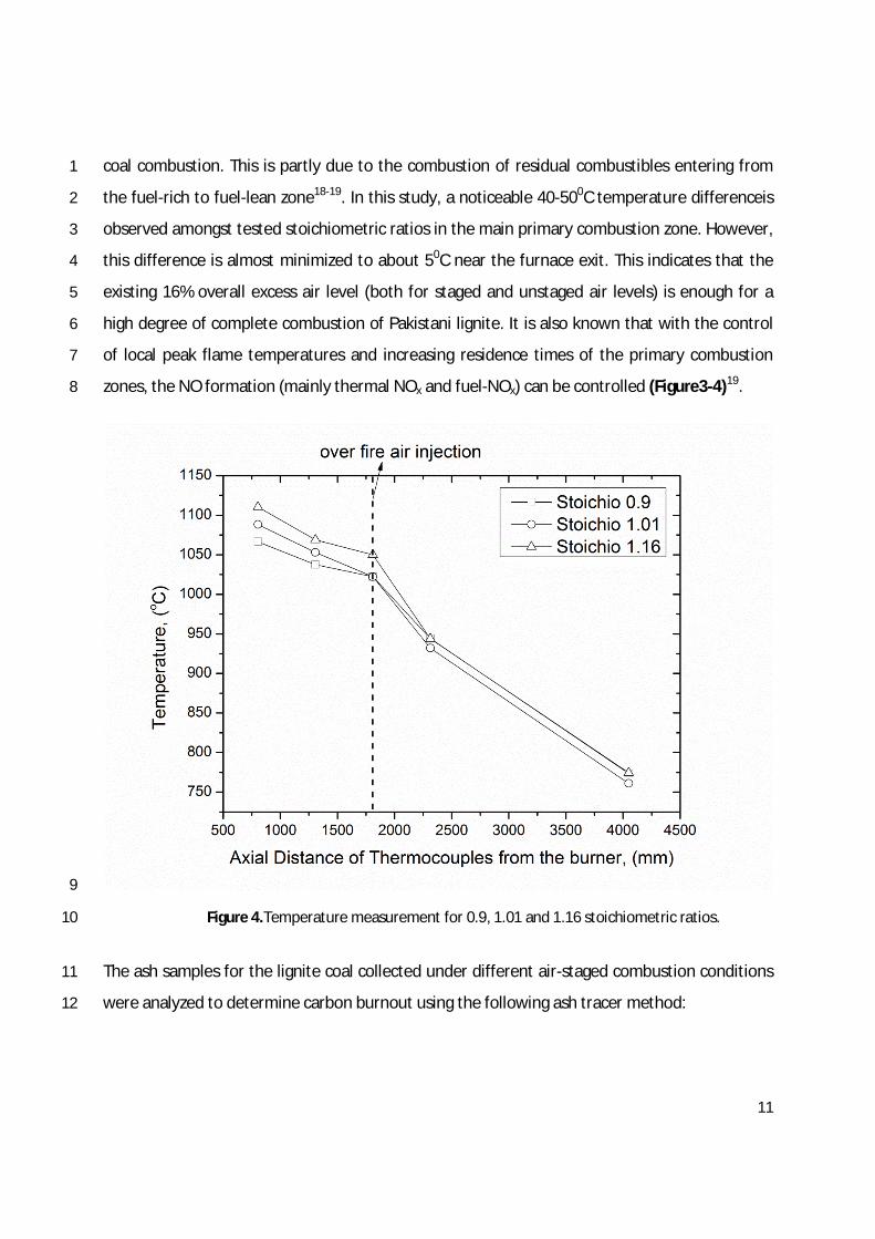
coal combustion. This is partly due to the combustion of residual combustibles entering from1
the fuel-rich to fuel-lean zone18-19. In this study, a noticeable 40-500Ctemperature differenceis2
observed amongst tested stoichiometric ratios in the main primary combustion zone. However,3
this difference is almost minimized to about 50C near the furnace exit. This indicates that the4
existing 16% overall excess air level (both for staged and unstaged air levels) is enough for a5
high degree of complete combustion of Pakistani lignite. It is also known that with the control6
of local peak flame temperatures and increasing residence times of the primary combustion7
zones, the NOformation (mainly thermal NOx and fuel-NOx) can be controlled (Figure3-4)19.8
9
Figure 4.Temperature measurement for 0.9, 1.01 and 1.16 stoichiometric ratios.10
The ash samples for the lignite coal collected under different air-staged combustion conditions11
were analyzed to determine carbon burnout using the following ash tracer method:12

12
kx
k
z
z
z
burnoutCarbon
1
1
(5)1
Where:z: dry ash mass fraction, k: ash content in the input solid fuel and x: ash content in the char2
sample.3
Figure5demonstrates the impacts of the variation of residence time of the primary combustion4
zone on carbon burnout. Lengthened residence time in the primary combustion5
zonecausesmarginally poor overall combustion efficiency due to the shorter burnout zone6
which is further compounded by lower temperatures within the primary combustion zone20.7
However, in the existing pilot-scale combustion tests the primary combustion zone8
temperature difference between20 un-staged and 22%level of air-staged combustion is 400C-9
500C; thisiseffectively reduced to 50Cup to the flue section of the furnace.At 16%excessair un-10
staged firing condition an overall carbon burnout level of 99.92%was obtained as compared to11
90.56% carbon burnout obtained at 22% level of air-staging. This suggests that an overall12
NOxreduction of 60%witha corresponding carbon burnout of 92.56%at 22%level of air-staged13
combustion condition is a feasible condition for Pakistani lignite combustion at a larger scale.14
Hence, 92.56%of carbon burnout result for 0.9 stoichiometric ratiosor 22%level of air-staging15
arenot the only advantagesin terms of reduced NO emissionsbut are also accompanied by a16
lesser impact on the overall combustion performance.17

13
1
Fig. 5. Carbon burnout for Pakistani lignite.2
3.3 Effect on slagging and fouling propensities3
Pakistani lignite coal ash samples collected from the pilot-scale combustion tests have been4
analysed using XRF technique(Table 3). The reported oxides of main heavy metals are utilized5
to establish slagging and fouling characteristics of the depositswhich collect on the radiant and6
heat recovery section of boilers, respectively.In previous work21-22, the slagging and fouling7
indiceshave been used to assess the propensity of fuel ash which generally causesheat transfer8
and corrosion related issues.9
It is observed in Table 3 that the reported chemical composition of the fly ash samples10
indicatesvery high levelsof Na2O, K2Oand CaOresulting in higher valuesof basic to acidic ratios11
of oxides. This has a direct influence on the slagging and fouling tendency of the resultant ash12
formations. The overall values for both fouling and slagging propensities were in the high to13

14
extremely high range indicating the necessity of boilers capable of compensating for1
higherlevelsof corrosion and lower heat transfer in the super heater and heat recovery sections2
of the boiler. During some combustion trials on a pilot FBC it is reported that Polish coal3
presentshighertendency for slagging and fouling than the Colombian coal23. It issuggested that4
a detailed analysison the slagging and fouling tendency should be performed to understand the5
interactions of co-firing Thar lignite and other fuels for power generation. Slagging and fouling6
deposits from a pulverized lignite fired power plant at West Macedonia, Greece was7
investigated.The major chemical constituents found were Fe2O3,CaO and SO3, while8
considerable contents of SiO2 and Al2O3were also detected24. In another study twenty samples9
from a main seam of Panian coalfield in Semirara Island, Antique Province, Philippines, were10
collected. Chemical analysis of the ash revealed high contents of Na, Mg, Fe, Ca, Ba and Sr. The11
strongly negative correlation of these elements with theash content indicates an organic12
affinity of the chemical elements of the seam. Owing to enrichment in alkali and alkali-earth13
elements,slagging and fouling indices indicate that the seam hasmedium to high propensity for14
slagging and a severe tendency for fouling25.15
In this study the percentage of iron oxide was found in the range of 18-21% whereas the16
percentage of alumina concentration was in the range of 14-16% for varying stoichiometric17
ratios. The concentrations of Na2O and K2O are generally dominating factors towards the18
fouling propensity in commercial boilers. The percentage of K2O is in the range of 0.5-0.8%19
whereasNa2Ois found in the range of 13-15%. The study also reported that the composition of20
these metallic oxides present in Tharparkar Lignite coal fly ash falls within the range of general21
lignite coal fly ash samples except iron oxide. Moreover, the combined percentage of oxides of22
Al, Fe and Si is about 67% close to 70% recommended for Portland cement blending.These23
percentages would have a direct non- trivial impact on the actual boiler furnace wall.It is24
important to mention that aside from the concentration of iron, sodium and potassium25
elements in oxide form, it is also important to know that what phases these oxides are present26
in product fly ash. The presence of iron oxide in resultant coal fly ash is mostly either in fayalite27
or magnetite phases. If present in magnetite form would be beneficial towards fire side tube28
passivation. Hence presence of iron oxide in magnetite form would help to mitigate the fire side29

15
corrosion. Similarly the presence of aluminosilicate phaseshelps towardsmitigating the basic to1
acidic ratio which then compensates the higher slagging and fouling propensities.2
Table 3.Metal oxidespresent in Pakistani lignite coal ash samplesat 1.16, 1.01 and 0.9stoichiometric3ratios.4
5
6
Metal Oxides
Unstaged Pakistanilignite coal ash
(SR= 1.16)
11%air-stagedPakistani lignite
coal ash
(SR= 1.01)
22%air-stagedPakistani lignite
coal ash
(SR= 0.9)
Typical26Lignite coalmetal oxidepresent in fly
ashSiO2 31.82 35.22 31.22 15-45TiO2 2.43 2.06 2.43 -Al2O3 16.21 14.43 16.19 10-25Fe2O3 17.95 21.27 18.34 4-15MnO 0.12 0.93 0.12 -MgO 0.60 0.30 0.50 3-10CaO 15.49 12.10 16.48 15-40Na2O 15.40 13.00 14.30 0-6K2O 0.56 0.87 0.53 0-4P2O5 0.1090 0.1020 0.11 -SO3 0.10 0.08 0.09 0-10ZnO 0.0006 0.0016 0.0006 -CuO 0.0010 0.0020 0.0009 -PbO 0.0001 0.0003 0.0001 -
2322
2232
TiOOAlSiO
OKONaMgOCaOOFe
A
B14-15, 21
0.99 0.92 1.01
322
32RA
BSimplified
OAlSiO
MgOCaOOFe
A
B
14-
15, 210.71 0.74 0.68
OKONaMgOCaOOFeRb 2232 14-15
50.00 50.15 47.54
OKONaA
BFu 22
14-1515.81 14.92 12.75
dSA
BRs
14-15where Sd =%of Sin
dry fuel3.04 3.09 2.82
Fu<0.6 low fouling inclination; Fu =0.6-40 high; Fu> 40 extremely highRS< 0.6 low slaggingInclination; RS=0.6-2.0 medium; RS=2.0-2.6 high; RS> 2.6 extremely high
B/A =Basic to acidic ratio; Rs: Slagging Index; Fu: Fouling Index
16
4. Conclusions1
Lignite coal obtained from Pakistan’s largest coal reserve in Tharparkar, Sindh(Block-VIII)was2
combusted in a 50kWth pilot-scale combustion furnace test facility. It was found that under a3
normal fuel to air ratio of 1.16 maximum NOx emissions of 165 ppmv at 6% O2 levels were4
observed. However, at 22%level of air-staging a maximum NOx reduction of 60%was achieved5
to lower the NOx emissions to 65ppmv at 6%O2. A noticeably higher level of inherent sulphur6
resulted in SO2 emissions in the range of 1380ppmv to 1550ppmv (@ 6% O2) for 0.9 to 1.167
stoichiometric ratios. An overall carbon burnout of 99.92%wasobtained for 1.16 stoichiometric8
ratio near the burner as compared to a carbon burnout of 99.56%for 0.9 stoichiometric ratioin9
the burner zone. The overall values for both fouling and slagging propensitieswere in the range10
of high to extremely high further indicating a dire need of either injection of specialized11
chemicals in the boilers to compensate for higher levels of corrosion and lower heat transfer in12
the boiler super heater and heat recovery sections or blending of lignite coal with relatively13
better quality coal.14
Acknowledgements15
The authorswish to acknowledges the enabling role of the Higher Education Commission,16
Islamabad, Pakistan and British Council, Islamabad for their financial support through ‘‘INSPIRE17
award (SP-254).”We also wish to thank Deep Rock Drilling Private Ltd (DRD)for provision of the18
coal samples. The authors would also like to appreciate the assistance by the INSPIRE team19
members, especially N. Irfan, A. Farooq, M. Jabeen, S. Munir and K. Harijan, for providing20
support in the project and enabling us for investigation of Thar coal at the University of Leeds,21
UK.22
References23
(1) Eurocoal. European Association for Coal and Lignite.24
www.euracoal.be/pages/ layout1sp_graphic.php?idpage=15.25
(2) Eurocol. Coal industry acrossEurope 2011,26
http:/ /www.euracoal.be/pages/medien.php?idpage=917.27
(3) Thomas, R.E.; Khan, M.R.; Khan, S.A. International Journal of Coal Geology 1993.28

17
(4) Pakistan Coal Power Generation Potential, 2004.1http:/ /www.nepra.org.pk/Policies/Coal%20Potential%20in%20Pakistan.pdf2
(5) Tippayawong, N.; Tantakitti, C.; Thavornun, S. American Journal of Applied Sciences2006, 33
(3): 1775-1780.4
(6) Dernjatin P, Savolaninen K, Takahashi Y, Shimogori M and Okazaki H. (2001). A High Efficient5
Combustion (NR-LE) Method for Lignite Firing Units. Power-Gen 2001 Europe.6
(7) Nikolopoulos, N.; Agraniotis, M.; Violidakis, I.; Karampinis, E.; Nikolopoulos, A.; Grammelis, P.;7Papapavlou, Ch.; Tzivenis, S.; Kakaras, E.Fuel2013, 113, 873–897.8
(8) RWEPower WTAtechnology. Amodern processfor treating and drying lignite.9
(9) Agraniotis, M.; Nikolopoulos, N.; NikolopoulosA.; Grammelis, P.; Kakaras, E. Fuel 2010, 89(12),103693–3709.11
(10) Glarborg, P.; Jensen, A.D.; Johnson, J.E. Progressin Energy and Combustion Science 2003,12
29, 89-113.13
(11) Normann, F.; Anderson, K.; Leckner, B.; Johnsson, F. Progressin Energy and Combustion14
Science 2009, 35, 385–397.15
(12) Nikolopoulos, A.; Malgarinos, I.; Nikolopoulos, N.; Grammelis, P.;Karrelas, S.; Kakaras, E. Fuel 2014,16115, 401-415.17
(13)Nikolopoulos, N.; Nikolopoulos, A.; Karampinis,E.; Grammelis, P.; Kakaras, E. Fuel 2011, 90(1), 198-18214.19
(14) Miller, J.A.; Bowman, C.T. Progressin Energy and Combustion Science1989, 15, 287-338.20
(15) Javed, M.T.; Irfan, N.; Gibbs, B.M. Journal of Environmental Management 2007, 251-289.21
(16) Daood S.S.; Javed, M.T.; Gibbs, B.M.; Nimmo, W. Fuel 2013, 105, 283-292.22
(17) Daood, S.S.; Nimmo, W.; Edge, P.; Gibbs, B.M. Fuel 2012, 101, 187-196.23
(18) Li, S.; Xu, T.; Sun, P.; Zhou, Q.; Tan, H.; Hui, S. Fuel 2008, 87, 723-731.24
(19) Li, S.; Xu, T.; Hui, S.; Zhou, Q.; Tan, H. Fuel ProcessingTechnology 2009, 90, 99-106.25
(20) Hesselmann, G.J. Fuel 1997, 76, 1269–1275.26
(21) Kazagic, A.; Smajevic, I. Energy 2007, 32, 2006-2016.27

18
(22) Masia, A.A.T.; Buhre, B.J.P.; Gupta, R.P.; Wall, T.F. Fuel ProcessingTechnology 2007, 88,1
1071-1081.2
(23) Teixeira, P.; Lopes, H.; Gulyurtlu, I.; Lapa, N.; Abelha, P. Biomassand Bioenergy 2 0 1 2, 39, 1 9 2-230 3.4
(24) Kostakis, G. Journal of HazardousMaterials2011, 18 ( 2–3), 1012-1018.5
(25)Limos-Martinez, S.M.; Watanabe, K. Fuel 2006, 85, 306–314.6
(26) USDepartment of Transportation. Federal Highway Administration. User guidelinesfor waster and7by product materials in Pavement Construction, Publication Number FHWA-RD-97-148.8