combustion efficiency analyzer 707 - tpi usa | test ... efficiency analyzer the value leader tm...
TRANSCRIPT

707Rev. 6.x Analyzers
Combustion Efficiency Analyzer
The Value LeaderTM
www.tpi-thevalueleader.com

IntroductionThank you for purchasing TPI brand products. The TPI 707 CarbonMonoxide Analyzer is a state of the art, easy to use analyzer designedto display carbon monoxide levels in and around appliances and work /living spaces. The instrument is ruggedly constructed and comes witha 3 Year unit and 2 Year sensor Guarantee.
General OverviewThe TPI 707 combustion analyzer uses a state of the art electrochemi-cal sensor. This sensor technology provides the longest lasting, mostaccurate and reliable means for performing tests. The sensor in youranalyzer will need to be replaced periodically and calibration is recom-mended once every year. The 707 will remind you when calibration isdue by flashing “CAL DUE Err” for three seconds at start up if the dateof calibration is one year or older.
Electrochemical sensors by nature are always active. Therefore thetime the analyzer is off and not being used must be taken into accountwhen determining sensor life. The sensor in your analyzer is warrantedfor two years. This warranty does not cover a sensor damaged throughmisuse of the analyzer.
You should keep the batteries of your 707 fresh so power is constantlybeing supplied to your sensor.
The following guidelines will help prevent damage to your sensor:
Always use the mini pump filter when performing tests.Always periodically check and replace the mini pump filter as needed.Always make sure the in-line filter / water trap is installed properly.Always periodically check and replace the in-line filter as needed.Always remove water or condensation from the inside of the in-line fil-ter / water trap assembly prior to performing tests.Always use the optional oil filter (p/n A773) when performing tests onoil burning equipment.
Contents
Introduction........................................................1General Overview.................................................1, 2Instrument Overview............................................. 3 ~ 7
Front View...............................................3Keypad.................................................. 4Back View...............................................5Side Views..............................................6Top View.................................................7
Basic Analyzer Functions........................................8, 9Analyzer Batteries..................................... 8Turning The Analyzer On & Fuel Selection........ 8, 9Turning The Analyzer Off............................. 9Activating The Backlight............................. 9
Carbon Monoxidse Analysis Overview........................ 10Testing for Carbon Monoxide in Ambient Air.................11, 12
Acceptable Levels of CO in Ambient Air............12Testing for Carbon Monoxide in Flues and Appliances.....13 ~ 21
Typical Test Locations.................................15 ~ 18Typical Test Results................................... 21
Setting Date & Time............................................. 22Storing Data....................................................... 23Recalling Data.................................................... 24Printing Data...................................................... 25, 26Specifications..................................................... 27 Calibration & Service............................................ 28Warranty........................................................... 28
Appendix A General Maintenance & Function Tests............29~ 31Appendix B A773 Sulfur Filter Installation & Maintenance....32, 33Appendix C Error Codes and Troubleshooting................... 34Appendix D CO Alarm & Auto Power Off..........................35Appendix E Manually Initializing Sensors........................36Appendix F Carbon Monoxide Facts...............................37Appendix G Carbon Monoxide Limits in Ambient Air Chart....38Appendix H Battery Replacement..................................39
1
Instrument OverviewFront View
Rubber Boot Protects the instrument from accidental damage
Display Large 3 Parameter Backlit LCD Display
Battery Condition Icon Shows condition of batteries.
Keypad Selects all available functions
General Overview (Continued)
Never over saturate your sensors by performing tests on equipmentwith gas levels beyond the capability of you analyzer.
Always keep the A794 water trap / filter assembly clean and replace thefilter as necessary. Replacement filter part number is A794F.
This manual will guide you through the functions of the TPI 707 whichwill give you many years of reliable service.
Your TPI 707 Flue Gas Analyzer comes complete with the followingstandard accessories:
• TPI 707 Instrument• Rubber Boot (A765)• Soft Carrying Case (A787)• Flue Sampling Probe (A69)• In-Line Filter assembly installed on Flue probw (A794)• Mini Pump Protection Filter Assembly and spare filters (A763)• Exhaust Spigot (removable) (A764)• Instruction Manual
( ) Denotes part number
Your TPI 707 Flue Gas Analyzer has the following options available: • Infrared printer (A740)• Spare In-Line Filter (A794F is a package of 5 filters)• Spare Water Block Filter (A794W is a package of 1 filter)
RubberBoot
LCDDisplay
Keypad
BatteryConditionIcon
NOTE: When performing tests on oil fired equipment be sureto use the optional oil filter (A773) or readings couldbecome erratic. See Appendix E for installationinstructions.
2 3
Keypad
4
Back View
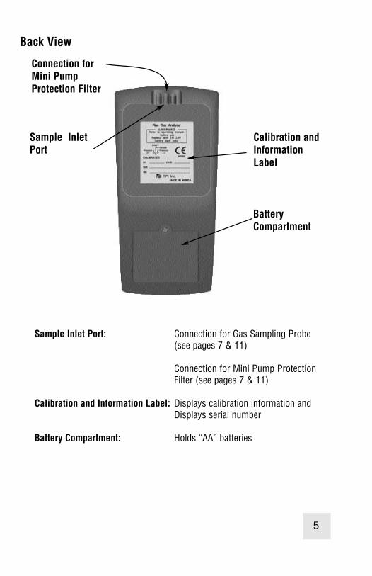
Sample Inlet Port: Connection for Gas Sampling Probe (see pages 7 & 11)
Connection for Mini Pump ProtectionFilter (see pages 7 & 11)
Calibration and Information Label: Displays calibration information andDisplays serial number
Battery Compartment: Holds “AA” batteries
Calibration andInformationLabel
BatteryCompartment
Connection forMini PumpProtection Filter
Sample InletPort
Store
Recall
ScrollEnter
Func
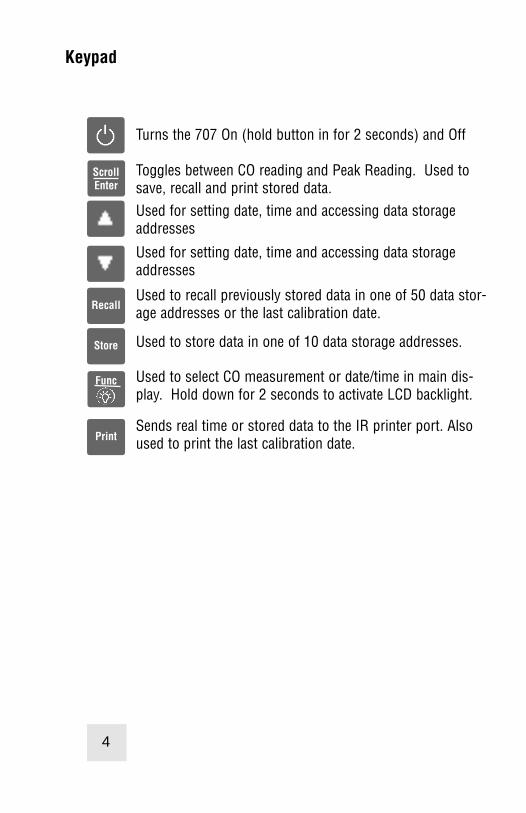
Turns the 707 On (hold button in for 2 seconds) and Off
Toggles between CO reading and Peak Reading. Used tosave, recall and print stored data.Used for setting date, time and accessing data storageaddresses
Used for setting date, time and accessing data storageaddresses
Used to recall previously stored data in one of 50 data stor-age addresses or the last calibration date.
Used to store data in one of 10 data storage addresses.
Used to select CO measurement or date/time in main dis-play. Hold down for 2 seconds to activate LCD backlight.
Sends real time or stored data to the IR printer port. Alsoused to print the last calibration date.
5
Keypad
4
Back View
Sample Inlet Port: Connection for Gas Sampling Probe (see pages 7 & 11)
Connection for Mini Pump ProtectionFilter (see pages 7 & 11)
Calibration and Information Label: Displays calibration information andDisplays serial number
Battery Compartment: Holds “AA” batteries
Calibration andInformationLabel
BatteryCompartment
Connection forMini PumpProtection Filter
Sample InletPort
Store
Recall
ScrollEnter
Func
Turns the 707 On (hold button in for 2 seconds) and Off
Toggles between CO reading and Peak Reading. Used tosave, recall and print stored data.Used for setting date, time and accessing data storageaddresses
Used for setting date, time and accessing data storageaddresses
Used to recall previously stored data in one of 50 data stor-age addresses or the last calibration date.
Used to store data in one of 10 data storage addresses.
Used to select CO measurement or date/time in main dis-play. Hold down for 2 seconds to activate LCD backlight.
Sends real time or stored data to the IR printer port. Alsoused to print the last calibration date.
5

Side Views
Exhaust Port Port for connection of Exhaust Adapter
Infrared Window Window for sending stored data to optional A740 IR Printer (see page 25 )
Rubber Boot Protects the instrument from accidental damage
ExhaustPort
InfraredWindow
RubberBoot
Top View
Gas Sample Port Connection for Mini Pump Protection Filter and Flue Probe (see pages 7 & 11)
6 7
Gas Sampling Port

BASIC ANALYZER FUNCTIONSAnalyzer BatteriesYour carbon monoxide analyzer is fitted with three AA size 1.5V alkaline bat-teries. It is important to keep battery power to the sensors in your analyzereven when it is not in use.
Your analyzer has a battery status indicator in the lower right corner of thedisplay. Battery status is determined as follows:
Indicates batteries are at full capacity.
Indicates batteries are at 2/3 capacity.
Indicates batteries are at 1/3 capacity. Replacement of batteriesshould be considered soon.
Indicates batteries are very low and in need of replacementimmediately. See Appendix H for battery replacement instructions.
Turning The Analyzer On Always: - Before turning on please ensure that the Mini Pump ProtectionFilter assembly the Tubing & In-Line Filter are not connected to the GasSample Port (see page 7)
The instrument MUST be turned on in a clean air environment as the initialpurge will set the Carbon Monoxide level to Zero. Press and hold down thePower Key and the TPI 707 will start its 30 second countdown 'PURGE' willbe displayed.
After start up, several tests can be performed to ensure proper function ofthe analyzer and flue probe. Please refer to Appendix A.
After the 30 second countdown the instrument is ready to take carbonmonoxide readings.
The 707 will auto power off if no keys have been pressed for 10 minutes andthe CO level is below 15ppm. Auto off can be disabled (see Appendix D). Theauto power off feature is always enabled upon power up.
Turning The Analyzer Off
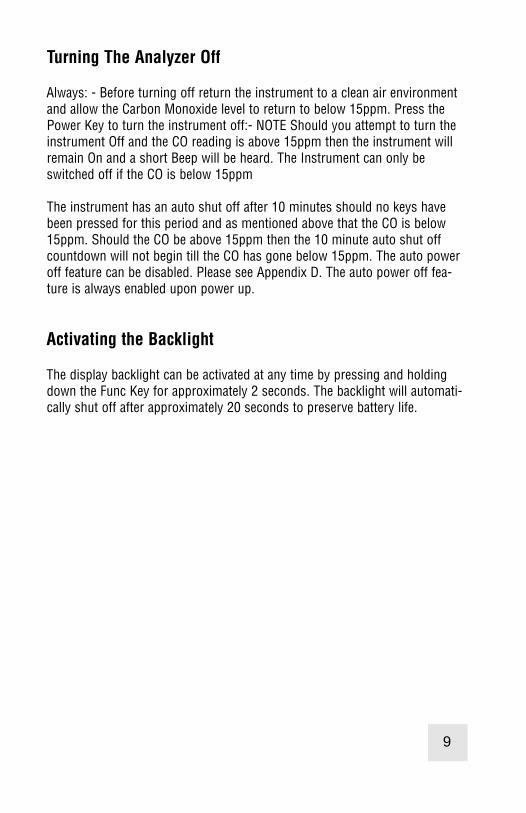
Always: - Before turning off return the instrument to a clean air environmentand allow the Carbon Monoxide level to return to below 15ppm. Press thePower Key to turn the instrument off:- NOTE Should you attempt to turn theinstrument Off and the CO reading is above 15ppm then the instrument willremain On and a short Beep will be heard. The Instrument can only beswitched off if the CO is below 15ppm
The instrument has an auto shut off after 10 minutes should no keys havebeen pressed for this period and as mentioned above that the CO is below15ppm. Should the CO be above 15ppm then the 10 minute auto shut offcountdown will not begin till the CO has gone below 15ppm. The auto poweroff feature can be disabled. Please see Appendix D. The auto power off fea-ture is always enabled upon power up.
Activating the Backlight
The display backlight can be activated at any time by pressing and holdingdown the Func Key for approximately 2 seconds. The backlight will automati-cally shut off after approximately 20 seconds to preserve battery life.
8 9
BASIC ANALYZER FUNCTIONSAnalyzer BatteriesYour carbon monoxide analyzer is fitted with three AA size 1.5V alkaline bat-teries. It is important to keep battery power to the sensors in your analyzereven when it is not in use.
Your analyzer has a battery status indicator in the lower right corner of thedisplay. Battery status is determined as follows:
Indicates batteries are at full capacity.
Indicates batteries are at 2/3 capacity.
Indicates batteries are at 1/3 capacity. Replacement of batteriesshould be considered soon.
Indicates batteries are very low and in need of replacementimmediately. See Appendix H for battery replacement instructions.
Turning The Analyzer On Always: - Before turning on please ensure that the Mini Pump ProtectionFilter assembly the Tubing & In-Line Filter are not connected to the GasSample Port (see page 7)
The instrument MUST be turned on in a clean air environment as the initialpurge will set the Carbon Monoxide level to Zero. Press and hold down thePower Key and the TPI 707 will start its 30 second countdown 'PURGE' willbe displayed.
After start up, several tests can be performed to ensure proper function ofthe analyzer and flue probe. Please refer to Appendix A.
After the 30 second countdown the instrument is ready to take carbonmonoxide readings.
The 707 will auto power off if no keys have been pressed for 10 minutes andthe CO level is below 15ppm. Auto off can be disabled (see Appendix D). Theauto power off feature is always enabled upon power up.
Turning The Analyzer Off
Always: - Before turning off return the instrument to a clean air environmentand allow the Carbon Monoxide level to return to below 15ppm. Press thePower Key to turn the instrument off:- NOTE Should you attempt to turn theinstrument Off and the CO reading is above 15ppm then the instrument willremain On and a short Beep will be heard. The Instrument can only beswitched off if the CO is below 15ppm
The instrument has an auto shut off after 10 minutes should no keys havebeen pressed for this period and as mentioned above that the CO is below15ppm. Should the CO be above 15ppm then the 10 minute auto shut offcountdown will not begin till the CO has gone below 15ppm. The auto poweroff feature can be disabled. Please see Appendix D. The auto power off fea-ture is always enabled upon power up.
Activating the Backlight
The display backlight can be activated at any time by pressing and holdingdown the Func Key for approximately 2 seconds. The backlight will automati-cally shut off after approximately 20 seconds to preserve battery life.
8 9

Carbon Monoxide Analysis OverviewPerforming carbon monoxide analysis is very important to the overall safetyof heating equipment and appliances. The following guidelines and descrip-tions are generic and meant to provide you with a basic understanding oftesting. TPI always recommends you contact the manufacturer of the deviceunder test, obtain information specific to the device, and follow the proce-dures and safety guidelines for performing tests and affecting repairs.
In general, for most applications, flue gas samples should be taken prior tothe draft diverter or any other opening that allows room air to enter the sys-tem. This prevents room air from mixing with gases in the flue and dilutingthe test sample.
Prior to taking a sample, the device under test should be on and operating.Putting the flue probe in the sample area prior to starting the device maycause saturation of the sensors due to the higher initial concentration of car-bon monoxide that may be encountered upon start up. If this happens, allowyour analyzer to purge in fresh air until the carbon monoxide level returns to0 ppm. This may take more than an hour depending on how saturated thesensor is.
The figures on pages 15 through 18 show locations for performing tests oncommonly encountered equipment. Remember to consult with the manufac-turer of the device under test for specific test information.
NOTE: Your 707 carbon monoxide analyzer is equipped with a highquality sensor that incorporates an on-board NO/NOx filter. This fil-ter prevents higher than normal CO readings caused by sensorcross sensitivity to NO/NOx, which is a byproduct of combustion.
When a gas appliance or hot water heater is operating properly, lit-tle or no CO will be produced. Older CO analyzers, and thoseequipped with sensors that do not have an on-board filter, willincorrectly read higher levels of CO because of the “NOx bump” orcross sensitivity to the NO/NOx present in the sample.
The NO/NOx cross sensitivity can increase the displayed readingby as much as 30ppm or more on analyzers with sensors that donot have the NO/NOx filter.
10
Testing for Carbon Monoxide in Ambient Air
Note: It is recommended you perform routine general maintenance on youranalyzer to ensure proper function. Please refer to Appendix A for generalmaintenance schedule and function tests.
1. Turn the 707 on in fresh air as outlined on page 8. After the initial purge cyclethe 707 will display the screen below.
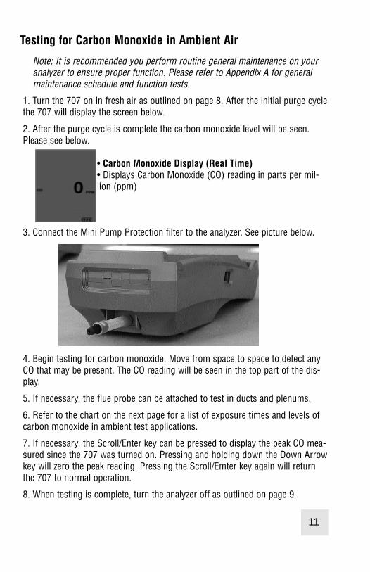
2. After the purge cycle is complete the carbon monoxide level will be seen.Please see below.
• Carbon Monoxide Display (Real Time)• Displays Carbon Monoxide (CO) reading in parts per mil-lion (ppm)
3. Connect the Mini Pump Protection filter to the analyzer. See picture below.
4. Begin testing for carbon monoxide. Move from space to space to detect anyCO that may be present. The CO reading will be seen in the top part of the dis-play.
5. If necessary, the flue probe can be attached to test in ducts and plenums.
6. Refer to the chart on the next page for a list of exposure times and levels ofcarbon monoxide in ambient test applications.
7. If necessary, the Scroll/Enter key can be pressed to display the peak CO mea-sured since the 707 was turned on. Pressing and holding down the Down Arrowkey will zero the peak reading. Pressing the Scroll/Emter key again will returnthe 707 to normal operation.
8. When testing is complete, turn the analyzer off as outlined on page 9.
11
Carbon Monoxide Analysis OverviewPerforming carbon monoxide analysis is very important to the overall safetyof heating equipment and appliances. The following guidelines and descrip-tions are generic and meant to provide you with a basic understanding oftesting. TPI always recommends you contact the manufacturer of the deviceunder test, obtain information specific to the device, and follow the proce-dures and safety guidelines for performing tests and affecting repairs.
In general, for most applications, flue gas samples should be taken prior tothe draft diverter or any other opening that allows room air to enter the sys-tem. This prevents room air from mixing with gases in the flue and dilutingthe test sample.
Prior to taking a sample, the device under test should be on and operating.Putting the flue probe in the sample area prior to starting the device maycause saturation of the sensors due to the higher initial concentration of car-bon monoxide that may be encountered upon start up. If this happens, allowyour analyzer to purge in fresh air until the carbon monoxide level returns to0 ppm. This may take more than an hour depending on how saturated thesensor is.
The figures on pages 15 through 18 show locations for performing tests oncommonly encountered equipment. Remember to consult with the manufac-turer of the device under test for specific test information.
NOTE: Your 707 carbon monoxide analyzer is equipped with a highquality sensor that incorporates an on-board NO/NOx filter. This fil-ter prevents higher than normal CO readings caused by sensorcross sensitivity to NO/NOx, which is a byproduct of combustion.
When a gas appliance or hot water heater is operating properly, lit-tle or no CO will be produced. Older CO analyzers, and thoseequipped with sensors that do not have an on-board filter, willincorrectly read higher levels of CO because of the “NOx bump” orcross sensitivity to the NO/NOx present in the sample.
The NO/NOx cross sensitivity can increase the displayed readingby as much as 30ppm or more on analyzers with sensors that donot have the NO/NOx filter.
10
Testing for Carbon Monoxide in Ambient Air
Note: It is recommended you perform routine general maintenance on youranalyzer to ensure proper function. Please refer to Appendix A for generalmaintenance schedule and function tests.
1. Turn the 707 on in fresh air as outlined on page 8. After the initial purge cyclethe 707 will display the screen below.
2. After the purge cycle is complete the carbon monoxide level will be seen.Please see below.
• Carbon Monoxide Display (Real Time)• Displays Carbon Monoxide (CO) reading in parts per mil-lion (ppm)
3. Connect the Mini Pump Protection filter to the analyzer. See picture below.
4. Begin testing for carbon monoxide. Move from space to space to detect anyCO that may be present. The CO reading will be seen in the top part of the dis-play.
5. If necessary, the flue probe can be attached to test in ducts and plenums.
6. Refer to the chart on the next page for a list of exposure times and levels ofcarbon monoxide in ambient test applications.
7. If necessary, the Scroll/Enter key can be pressed to display the peak CO mea-sured since the 707 was turned on. Pressing and holding down the Down Arrowkey will zero the peak reading. Pressing the Scroll/Emter key again will returnthe 707 to normal operation.
8. When testing is complete, turn the analyzer off as outlined on page 9.
11
Testing for Carbon Monoxide in Flues & Appliances
Note: It is recommended you perform routine general maintenance on youranalyzer to ensure proper function. Please refer to Appendix A for generalmaintenance schedule and function tests.
1. Turn the 707 on in fresh air as outlined on page 8. After the initial purgecycle the 707 will display the screen below.
• Carbon Monoxide Display (Real Time)• Displays Carbon Monoxide (CO) reading in parts per million(ppm)
2. Connect the Mini Pump Protection Filter assembly and Flue Probe to theGas Sample Port. (See below & page 7)
IMPORTANT: Prior to taking a sample, the device under test should be on andat operating temperature. Putting the flue probe in the sample area prior tostarting the device may cause saturation of the sensors due to the higherinitial concentration of carbon monoxide that may be encountered uponstart up. If this happens, allow your analyzer to purge in fresh air until thecarbon monoxide level returns to 0 ppm. This may take more than an hourdepending on how saturated the sensors are.
13
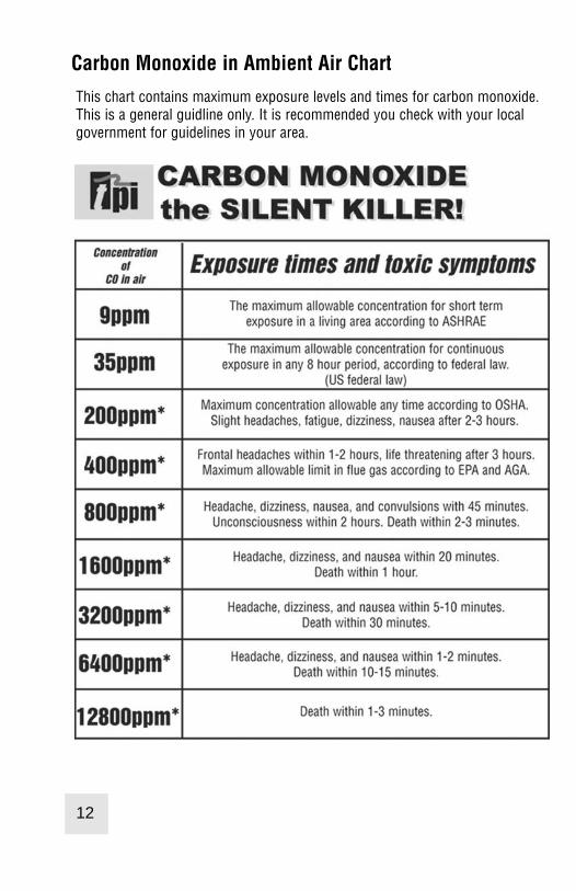
Carbon Monoxide in Ambient Air Chart
This chart contains maximum exposure levels and times for carbon monoxide.This is a general guidline only. It is recommended you check with your localgovernment for guidelines in your area.
12

Testing for Carbon Monoxide in Flues & Appliances
Note: It is recommended you perform routine general maintenance on youranalyzer to ensure proper function. Please refer to Appendix A for generalmaintenance schedule and function tests.
1. Turn the 707 on in fresh air as outlined on page 8. After the initial purgecycle the 707 will display the screen below.
• Carbon Monoxide Display (Real Time)• Displays Carbon Monoxide (CO) reading in parts per million(ppm)
2. Connect the Mini Pump Protection Filter assembly and Flue Probe to theGas Sample Port. (See below & page 7)
IMPORTANT: Prior to taking a sample, the device under test should be on andat operating temperature. Putting the flue probe in the sample area prior tostarting the device may cause saturation of the sensors due to the higherinitial concentration of carbon monoxide that may be encountered uponstart up. If this happens, allow your analyzer to purge in fresh air until thecarbon monoxide level returns to 0 ppm. This may take more than an hourdepending on how saturated the sensors are.
13
Carbon Monoxide in Ambient Air Chart
This chart contains maximum exposure levels and times for carbon monoxide.This is a general guidline only. It is recommended you check with your localgovernment for guidelines in your area.
12

TYPICAL TEST LOCATIONSHot Water Heater
The flue probe must be inserted into the fire tube under the draft diverter. Thisprevents the sample from being diluted. It may be necessary to drill a hole in thediverter. The optional A797 flexible draft probe can be used to perform this testwithout drilling a hole. Please refer to the figures below.
If necessary, drill a hole through the draftdiverter to enable the flue probe to beinserted down into the fire tube. Cover thehole when the test is complete. Theoptional TPI flexible draft probe part num-ber A797 can be used without drilling ahole.
3. For testing in a flue, drill a 1/4 inch hole into the flue of the device undertest. For most applications, flue gas samples should be taken prior to thedraft diverter or any other opening that allows room air to enter the system.This prevents room air from mixing with gases in the flue and diluting thetest sample.
Note: If performing a test on a hot water heater insert the probe directlydown into the top of the water heater exhaust tube (fire tube). Measuring inthe gap between the hood and the exhaust pipe will not provide an accuratereading due to dillution of the sample. Please see the figure on page
It is important to use manufacturers recommended test locations wheneverpossible.
Refer to the figure below for calculating the sample hole location.
The figures on the following pages show typical test locations on commonlyencountered equipment.
14 15

17
Condensing Boiler / Furnace
Typical Test Locations
TYPICAL TEST LOCATIONS
It is important to use manufacturers recommended test locationswhenever possible.
TYPICAL TEST LOCATIONS
Atmospheric Gas Fired Fan Assist Boiler / Furnace
Typical Test Locations
It is important to use manufacturers recommended test locationswhenever possible.
16
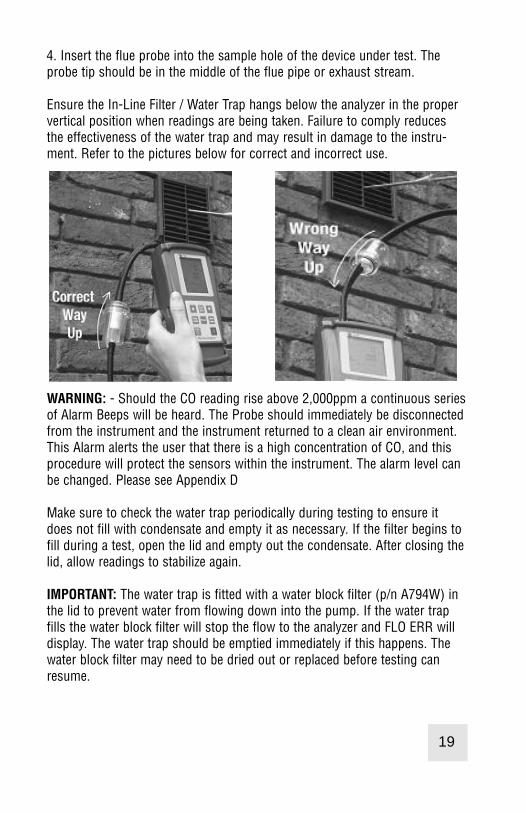
4. Insert the flue probe into the sample hole of the device under test. Theprobe tip should be in the middle of the flue pipe or exhaust stream.
Ensure the In-Line Filter / Water Trap hangs below the analyzer in the propervertical position when readings are being taken. Failure to comply reducesthe effectiveness of the water trap and may result in damage to the instru-ment. Refer to the pictures below for correct and incorrect use.
WARNING: - Should the CO reading rise above 2,000ppm a continuous seriesof Alarm Beeps will be heard. The Probe should immediately be disconnectedfrom the instrument and the instrument returned to a clean air environment.This Alarm alerts the user that there is a high concentration of CO, and thisprocedure will protect the sensors within the instrument. The alarm level canbe changed. Please see Appendix D
Make sure to check the water trap periodically during testing to ensure itdoes not fill with condensate and empty it as necessary. If the filter begins tofill during a test, open the lid and empty out the condensate. After closing thelid, allow readings to stabilize again.
IMPORTANT: The water trap is fitted with a water block filter (p/n A794W) inthe lid to prevent water from flowing down into the pump. If the water trapfills the water block filter will stop the flow to the analyzer and FLO ERR willdisplay. The water trap should be emptied immediately if this happens. Thewater block filter may need to be dried out or replaced before testing canresume.
19
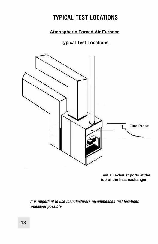
Test all exhaust ports at thetop of the heat exchanger.
Atmospheric Forced Air Furnace
Typical Test Locations
TYPICAL TEST LOCATIONS
It is important to use manufacturers recommended test locationswhenever possible.
18
4. Insert the flue probe into the sample hole of the device under test. Theprobe tip should be in the middle of the flue pipe or exhaust stream.
Ensure the In-Line Filter / Water Trap hangs below the analyzer in the propervertical position when readings are being taken. Failure to comply reducesthe effectiveness of the water trap and may result in damage to the instru-ment. Refer to the pictures below for correct and incorrect use.
WARNING: - Should the CO reading rise above 2,000ppm a continuous seriesof Alarm Beeps will be heard. The Probe should immediately be disconnectedfrom the instrument and the instrument returned to a clean air environment.This Alarm alerts the user that there is a high concentration of CO, and thisprocedure will protect the sensors within the instrument. The alarm level canbe changed. Please see Appendix D
Make sure to check the water trap periodically during testing to ensure itdoes not fill with condensate and empty it as necessary. If the filter begins tofill during a test, open the lid and empty out the condensate. After closing thelid, allow readings to stabilize again.
IMPORTANT: The water trap is fitted with a water block filter (p/n A794W) inthe lid to prevent water from flowing down into the pump. If the water trapfills the water block filter will stop the flow to the analyzer and FLO ERR willdisplay. The water trap should be emptied immediately if this happens. Thewater block filter may need to be dried out or replaced before testing canresume.
19
Test all exhaust ports at thetop of the heat exchanger.
Atmospheric Forced Air Furnace
Typical Test Locations
TYPICAL TEST LOCATIONS
It is important to use manufacturers recommended test locationswhenever possible.
18

Typical Test Results
Actual test results vary depending on the equipment undertest. TPI recommends you check with the manufacturer of theequipment being tested to determine specific acceptableresults.
Power Burners (Gas Fired)
Power Burners (Oil Fired)
Gas Fired Burners (Atmospheric / Fan Assist)
21
5. Allow the readings to stabilize. The CO concentration in ppm can be seen.
NOTE: Your 707 carbon monoxide analyzer is equipped with a highquality sensor that incorporates an on-board NO/NOx filter. This fil-ter prevents higher than normal CO readings caused by sensorcross sensitivity to NO/NOx, which is a byproduct of combustion.
When a gas appliance or hot water heater is operating properly, lit-tle or no CO will be produced. Older CO analyzers, and thoseequipped with sensors that do not have an on-board filter, willincorrectly read higher levels of CO because of the “NOx bump” orcross sensitivity to the NO/NOx present in the sample.
The NO/NOx cross sensitivity can increase the displayed readingby as much as 30ppm or more on analyzers with sensors that donot have the NO/NOx filter.
6. The Scroll/Enter key can be pressed to display the peak CO reading.Pressing and holding down the Down Arrow key will zero the peak reading.Pressing the Scroll/Enter key will return the 707 to normal operation.
20
Less than 100ppm Carbon Monoxide in the flue
Hot Water Heater
Less than 50ppm Carbon Monoxide in the fire tube
Less than 100ppm Carbon Monoxide in the flue
Less than 100ppm Carbon Monoxide in the flue
Levels Near Properly Adjusted Gas Stoves
Less than 15ppm Carbon Monoxide
Default displayshows CarbonMonoxide (CO) inparts per million(ppm)
Peak display showsthe highest amountof Carbon Monoxide(CO) measured inparts per million(ppm) since start up.

STORING DATA
During testing data can be stored for later retrieval.
When data is saved, all data previously in the address will be overwrit-ten.When saving pressure/draft readings, select an address different fromthe one used to save combustion readings.
1. Press the Store Key. To cancel storing information press the Store Keyand use the Up/Down Arrow Keys to select “Yes” and press theScroll/Enter Key.
2. “Addr” and an address location from 0 to 49 will flash on the display. Usethe Up/Down Arrow Keys to select the desired location to store the dataand press the Scroll/Enter Key. To cancel storing information press theStore Key and use the Up/Down Arrow Keys to select “Yes” and press theScroll/Enter Key.
3. The data is stored and “End” will display. Use the Up/Down Arrow Keys toselect “Yes” to stop storing data and return to normal operation or select“No” to store data again. Press the Scroll/Enter Key.
You have just successfully stored a set of readings which can be reviewedon screen (see page 24) or sent to the IR printer (see page 25).
23
SETTING DATE AND TIME
With the analyzer running, press the Func Key to access the date/time screen.From this function Time, Date and Year can be changed.
If the Date and Time do not need to be changed, press the Func Key tobypass this function and return the 712 to combustion analyzer mode(Function 1).
1. Once the Time, Date, and Year screen is displayed, press the Scroll/EnterKey once to allow you to change the data.
2. Press the Up Arrow Key to Increase the Minutes.
3. Press the Down Arrow Key to Decrease the Minutes.
4. Press the Scroll/Enter Key to confirm the desired Minute and move ontothe Hours.
5. Repeat steps 2 to 4 to change the Hour, the Day, the Month and the Year.
6. Once the date and time has been set press the Func Key to return to nor-mal use.
Function Display 4 (Date / Time)TimeDate / MonthYear
22

PRINTING DATA
WARNING: - To operate correctly there must be a clear line of sight betweenthe Infrared Window on the instrument (see page 6) and the Infrared Windowon the IR Printer (see Printer instructions). Place the printer so it is no closerthan approximately 6 inches from the analyzer.
1. Press the Print Key once 'rEAL', “Stor’, and “Cal” will be displayed and‘rEAL’ will be flashing. To cancel printing press the Print Key and use theUp/Down Arrow Keys to select “Yes” and press the Scroll/Enter Key.
Selecting ‘rEAL’ will cause the 707 to print the test data currently on thedisplay (real time data). Selecting ‘Stor’ will cause the 707 to print datastored in memory. Selecting “Cal” will cause the 707 to print the last dateof calibration. Use the Up and Down Arrow Keys to select the desiredprint mode and press the Scroll/Enter Key.
REAL Print Mode - If rEAL print mode is selected, the analyzer will dis-play ‘Wait’ ‘out’ and bars will change position on the LCD until printing iscomplete.
STOR Print Mode - If Stor mode is selected, 'Addr' will be displayed onthe top line along with 'SA ' and a location number from 0 to 49 will beflashing on the screen. Select the required address location that you wishto print data from by pressing the Up and Down Arrow Keys and pressthe ‘Scroll/Enter’ Key. The analyzer will display ‘Wait’, ‘out’ and bars willchange position on the LCD until printing is complete.
CAL Print Mode - If Cal print mode is selected, the analyzer will display‘Wait’ ‘out’ and bars will change position on the LCD until printing is com-plete.
After printing is complete, ‘End’ will be displayed and ‘YES’ (or ‘no’) willblink. Selecting ‘YES’ will return the 707 to normal operation, selecting‘no’ will return the 707 to the print selection screen so you can printagain. Use the Up and Down Arrow Keys to make the selection and pressthe Scroll/Enter Key.
25
RECALLING DATAThe recall feature allows you to display stored data or retrieve the last date ofcalibration.
Recalling Saved Data or Calibration Date1. Press the Recall button once.2. The display will show “Stor” and “Cal”. Use the Arrow buttons
to select the desired function.To cancel recalling information pressthe Recall Key and use the Up/Down Arrow Keys to select “Yes” and press the Scroll/Enter Key.
Stor - Selecting “Stor” allows you to display the information in a memory location.
1. Press the Recall button once. The display will show “Stor” and “Cal”. Using the Arrow buttons select “Stor” by making it blink.Press the Scroll/Enter button.
2. “Addr” will be displayed and a number from 0 to 49 will flash.
3. Using the up and down arrows, select the memory location of the readings you want to display.
4. Press the Scroll/Enter key once. The 707 will display the date and time screen showing when that reading was stored.
5. Use the up and down arrows to scroll through the data that was saved.
6. Press the Scroll/Enter button and “End” will be displayed and “Yes” will flash. Press the Scroll/Enter button if you are finished recalling data or use the Arrow buttons to select No to recall data from other locations.
CAL - Selecting “CAL” allows you to display the last date of cali-bration.
1. Press the Recall button once. The display will show “Stor” and “Cal”. Using the Arrow buttons select “Cal” by making it blink. Press the Scroll/Enter button.
2. “CAL” will blink and the last calibration date will be displayed in DD/MM.YYYY format.
3. Press the Scroll/Enter button, “End” will be display and YES willblink. Press the Scroll/Enter button to return to normal operation.24

SPECIFICATIONS
InstrumentOperating Temperature Range 14°F to +122°F (-10°C to +50°C)Battery 1.5V AA size (3)Battery Life > 6 HoursDisplay Backlit LCDData Storage 50 sets of readingsTime & Date 24 Hour Real Time ClockDimensions 200mm x 90mm x 60mmWeight 500gCasing Rubber Boot as StandardSwitch Off FailsafeExhaust Safety SpigotConforms to BS7927 (and the draft BS7967)
Flue Temperature ProbeConstruction Straight Grip with Stainless Steel ShaftHose Length Approximately 5 feetInsertion Length 200mmMaximum Temperature 700°C for 5 minutes
AccuracyRange Resolution Accuracy
Carbon Monoxide 0-10,000 ppm 1 ppm +/- 5 ppm or 5%Whichever is greater
27
PRINTING DATA (Continued)
Printout Interpretation
Data from test is print-ed here.
Date and time of test.
Customer informationand signed confirma-tion of test.(Fill in this data andhave the customersign for confirmation.)
26

Appendix A: General MaintenanceAll carbon monoxide analyzers use consumable items such filters and probes.These items are user serviceable and can be taken care of by the operator.
The consumable items that will require operator attention are the water trap / fil-ter assembly, flue probe, and pump protection filter.
The recommended maintenance schedule for your analyzer is as follows:
Maintenance Performed FrequencyWater trap Check Once per week (Once per day for analyzersFilter Check that see heavy use or are used in oil fired
applications) Pump Operation Check Once per month (More often for analyzersFlue Probe Integrity Check that see heavy use or are used in oil fired
applications)
Water Trap CheckVisually check the water trap for:
1. Cracks in the bowl.2. Broken ears on the bowl where the lid locks on.3. Broken ears on the lid.4. Worn out o-ring on the lid.5. Loose connection to the flue probe tubing.
Filter Check
Signs of dirty or water saturated filters are a slow pump, flow error displayedwhen the flue probe is connected, and measurements that take longer than nor-mal.
TPI analyzers use three filters to protect the pump and sensors. The first filter tocheck is the A763 mini pump protection filter. (see picture below)
Strain Relief Spring Inspection Window
A763 Pump Protection Filter
Look in the inspection window to check the filter. When the filter materialbecomes dark, pull the black nose cone out of the tubing and replace the ball fil-ter inside.
29
CALIBRATION & SERVICE
It is recommended that your analyzer be calibrated every 12 months. Whencalibration is due the analyzer will remind you by flashing “CAL DUE Err” atstart up and then return to normal operation. Please consult Test ProductsInternational for further details or send your analyzer to the address belowfor service.
TPI / Attn. Repair9615 SW Allen Blvd. Suite 104Beaverton, OR 97005
The following are consumable parts for the instrument:
In-Line Filter Element (pkg of 5) User Replaceable A794FMini Pump Protection Filter Assem. User Replaceable A763 **Oxygen Sensor User / Factory Replaceable A761**Carbon Monoxide Sensor User / Factory Replaceable A760**Sensor replacement requires calibration gas.
WARRANTY
Your TPI 707 Flue Gas Analyzer is guaranteed free from defects in materialsand workmanship for 3 Years from the date of purchase. This guarantee doesnot affect your statuary rights. For additional information please refer to theincluded warranty card or contact TPI at 800-368-5719.
To obtain warranty performance or maintenance on your analyzer: - Includewith the product your name, address, phone number, written description ofthe problem and proof of purchase date. Carefully package and return to:
TPI / Attn. Repair9615 SW Allen Blvd. Suite 104Beaverton, OR 97005
28

Appendix A: General Maintenance (continued)
Flue Probe Integrity Check
NOTE: Perform this check after performing the Pump Operation Check outlinedon the previous page.
1. Turn the analyzer on as outlined on page 8. Do not connect anything to theinlet. Wait until the analyzer has completed the initial purge and sensor checkand is operating normally prior to proceeding to step 2.
2. Connect the A763 mini pump protection filter and flue probe assembly to theinlet of the analyzer.
3. Cover the end of the flue probe with a small piece of tube and pinch the endclose. After a short period of time the analyzer should display “FLO ERR” and arapid beeping should be heard. If this happens the flue probe his operatingproperly and the integrity test is complete. If the analyzer does not display “FLOERR” this is an indication of a possible leak somewhere in the flue probe andyou may proceed to the next step for further tests.
5. Pinch the hose below the handle of the flue probe. If the analyzer displays“FLO ERR” there is a leak in the handle assembly and the probe needs to be fac-tory serviced. If the analyzer does not display “FLO ERR” proceed to the nextstep for further tests.
6. Pinch the hose between the analyzer and the water trap. If “FLO ERR” stilldoes not display there may be an internal leak, pump problem, or other issueand the analyzer needs to be factory serviced. If “FLO ERR” is displayed there isa leak in the water trap assembly and the water trap assembly should bechecked as outlined on page 39 & 40.
31
Appendix A: General Maintenance (continued)Filter Check Continued
The other two filters are located in the water trap. The main filter is the A794Fparticle filter. This filter stops debris and dust from traveling down to the analyz-er. The secondary filter is the A794W water block filter. This filter stops flow inthe event the water trap fills with condensate. Refer to the picture below.
Open the water trap and look at the A794F particle filter. The filter will typicallyget dirty from the inside first. If the filter is dark on the inside a replacement fil-ter should be installed.
If the A794F is clean but saturated with water a replacement should be installedto ensure proper flow. The saturated filter can be left to dry and reused later.
Pump Operation Check
1. Turn the analyzer on as outlined on page 8. Do not connect anything to theinlet. Wait until the analyzer has completed the initial purge and sensor checkand is operating normally prior to proceeding to step 2.
2. Cover the analyzer inlet with your finger. The analyzer should display “FLOERR” and a rapid beeping should be heard.
If the analyzer does not beep and display “FLO ERR” this may be an indicationthe flow sensor requires calibration, the pump is faulty, or there is an internalleak. The analyzer should be returned for factory service.
Water trap bowl. A794water trap pictured. A795water trap is similar butlonger
A794FParticle Filter
A794WWaterBlock Filter
Water trap lid. O-ring islocated in the lid recess
A794D FilterSpacer Disc
30
Appendix B: A773 SULFUR FILTER INSTALLATION & MAINTENANCE
4. Beginning on the “Flue Probe” side of the A773 sulfur filter, pull the yellowthermocouple cord out of the channel of the flue probe tube. Pull out approx-imately the length of the water trap that was removed.
5. Being careful not to cut the yellow cord, cut out a section of the flue probetubing the length of the water trap on the “Flue Probe” side of the A773 sul-fur filter. (See picture below)
6. Install the water trap in the flue probe hose where the piece was cut out. Makesure the water trap is positioned correctly. The water trap lid should face the“Hose End” side of the hose.
A773 SULFUR FILTER MAINTENANCE:
The A773 should be replaced when most of the pellets become discolored, usual-ly white or black.
If the A773 begins to trap condensate and fill with water but the pellets are notdiscolored to the point replacement is required, it should be removed and allowedto dry. Once it is dry it can be reused.
33
Appendix B: A773 SULFUR FILTER INSTALLATION & MAINTENANCE
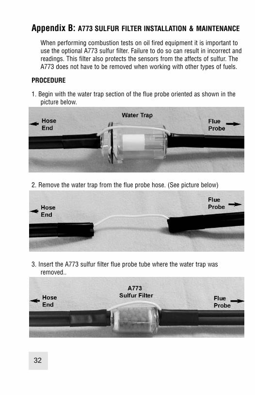
When performing combustion tests on oil fired equipment it is important touse the optional A773 sulfur filter. Failure to do so can result in incorrect andreadings. This filter also protects the sensors from the affects of sulfur. TheA773 does not have to be removed when working with other types of fuels.
PROCEDURE
1. Begin with the water trap section of the flue probe oriented as shown in thepicture below.
2. Remove the water trap from the flue probe hose. (See picture below)
3. Insert the A773 sulfur filter flue probe tube where the water trap wasremoved..
32

Appendix B: A773 SULFUR FILTER INSTALLATION & MAINTENANCE
4. Beginning on the “Flue Probe” side of the A773 sulfur filter, pull the yellowthermocouple cord out of the channel of the flue probe tube. Pull out approx-imately the length of the water trap that was removed.
5. Being careful not to cut the yellow cord, cut out a section of the flue probetubing the length of the water trap on the “Flue Probe” side of the A773 sul-fur filter. (See picture below)
6. Install the water trap in the flue probe hose where the piece was cut out. Makesure the water trap is positioned correctly. The water trap lid should face the“Hose End” side of the hose.
A773 SULFUR FILTER MAINTENANCE:
The A773 should be replaced when most of the pellets become discolored, usual-ly white or black.
If the A773 begins to trap condensate and fill with water but the pellets are notdiscolored to the point replacement is required, it should be removed and allowedto dry. Once it is dry it can be reused.
33
Appendix B: A773 SULFUR FILTER INSTALLATION & MAINTENANCE
When performing combustion tests on oil fired equipment it is important touse the optional A773 sulfur filter. Failure to do so can result in incorrect andreadings. This filter also protects the sensors from the affects of sulfur. TheA773 does not have to be removed when working with other types of fuels.
PROCEDURE
1. Begin with the water trap section of the flue probe oriented as shown in thepicture below.
2. Remove the water trap from the flue probe hose. (See picture below)
3. Insert the A773 sulfur filter flue probe tube where the water trap wasremoved..
32

Appendix C: ERROR CODES & TROUBLESHOOTING
The 707 analyzer will display certain codes to let you know of a malfunction.Code
DisplayedCode Definition Possible Causes Corrective Action
FloErr
Pump not drawing sample atcorrect flow rate.
Blockage / kink in flue probehose.
Dirty or blocked filter(s).
Worn pump.
Check and rectify.
Replace filter(s).
Return to TPI for service.
InItCOErr
Carbon monoxide sensorfailed to initialize.
Flue probe connected to 707prior to power up.
707 did not purge completelyfrom last sample.
Worn or defective carbonmonoxide sensor.
Disconnect probe andrestart.
Purge for 20 minutes andrestart.
Return to TPI for sensorreplacement or install newsensor.*
Try manually initializing thesensor. See Appendix G.
Lobat
Low battery. Battery needs to be charged. Charge battery. If the batterywon’t hold a charge, replacethe battery.
oFL Overflow indication. The car-bon monoxide being mea-sured is above the instru-ments capability.
CO being measured is toohigh or low.
Remove the CO source andallow the 707 to purge.
*Sensor replacement requires calibration gas.
34
Appendix D: CO ALARM & AUTO OFF SETTINGS
Setting the Carbon Monoxide Alarm Point and/or Auto Power Off Mode
The CO alarm and auto power off settings can be changed as necessary byperforming the following procedure.
WARNING : Changing parameters in field calibration mode can adverselyaffect the operation of your analyzer. Follow the instructions carefully.
1. Press and hold the FUNC and Down Arrow keys for approximately 5 secondsuntil a beep is heard. Press and hold the Scroll/Enter Key down until ‘FILDCAL’ is displayed. The 707 will cycle through a 30 second countdown thendisplay ‘CAL’, Air’, gAS’.
2. Use the Up Arrow Key to select ‘Air’ by making it blink. Press the Scroll/EnterKey to accept the selection.
3. 707 Display: ‘CAL’, ‘FLo’, ‘oPEn’. Action : Press the Func Key to bypass.
4. 707 Display: ‘CAL’, ‘FLo’, ‘CLos’. Action : Press the Func Key to bypass.
5. 707 Display: ‘0ppm’, ‘Co’, ‘rEF’. Action : Press the Func Key to bypass.
6. 707 Display: ‘2000’, ‘A-r’, ‘SEt’. Action : If you are not changing the CO alarmpoint press the Func Key. Otherwise press the Up and Down Keys to set theppm level the alarm will sound at. Factory default is 2000ppm. Press theScroll/Enter Key to accept the selection.
7. 707 Display: ‘Auto’, ‘oFF’, ‘En’. Action : If you are not changing the auto poweroff mode press the Func Key. Otherwise press the Up and Down Arrow Keysto enable (En) or disable (dis) the auto off function. Factory default is enabled(En). Press the Scroll/Enter Key to accept the selection.
8. 707 Display: ‘CAL’, ‘StoP’, ‘go’. Action : Press the Up Arrow Key to select‘StoP’ by making it blink and press the Scroll/Enter Key to accept the selec-tion. The 707 will return to normal operation
35
Appendix E: MANUALLY INITIALIZING SENSOR
If the CO or O2 sensor fails to initialize, this procedure can be performed totry and manually initialize the sensor(s).
WARNING : Changing parameters in calibration mode can adversely affect theoperation of your analyzer. Follow the instructions carefully.
1. Turn the analyzer on. When the countdown reaches 26, press and hold downthe Up Arrow, Scroll/Enter, and Down Arrow keys together for approximately5 to 7 seconds. The analyzer will beep and “Fact Cal” will be displayed.Release the keys. The analyzer will cycle through a 30 second countdownthen display ‘CAL’, Air’, gAS’.
2. Use the Up Arrow Key to select ‘Air’ by making it blink. Press the Scroll/EnterKey to accept the selection.
3. 707 Display: ‘CAL’, ‘FLo’, ‘oPEn’. Action : Press the Func Key to bypass.
4. 707 Display: ‘CAL’, ‘FLo’, ‘CLos’. Action : Press the Func Key to bypass.
5. 707 Display: ‘0ppm’, ‘Co’, ‘rEF’. Action : Press the Scroll/Enter Key. After the10 second countdown is complete press the Scroll/Enter Key twice.
6. 707 Display: ‘2000’, ‘A-r’, ‘SEt’. Action : Press the Func Key to bypass.
7. 707 Display: ‘Auto’, ‘oFF’, ‘En’. Action : Press the Func Key to bypass.
8. 707 Display: ‘CAL’, ‘StoP’, ‘go’. Action : Press the Up Arrow Key to select‘StoP’ by making it blink and press the Scroll/Enter Key to accept the selec-tion. The 707 will return to normal operation
If the 707 continues to fail to automatically initialize or this procedure failsto initialize the sensors, return your analyzer to Test ProductsInternational.
36
Appendix F: CARBON MONOXIDE FACTS
Carbon Monoxide (CO) is invisible, odorless, and tasteless. It is the byproduct ofcombustion and levels are elevated when there is incomplete combustion.
Sources of CO include: Unvented kerosene and gas space heatersLeaking chimneys & furnaces Gas water heaters Back drafting from furnaces Wood stoves& fireplaces Gas Stoves Automobile exhaust Tobacco smoke
Carbon Monoxide is picked up quickly in the body by red blood cells. At high lev-els of CO the body replaces oxygen with carbon monoxide.
The most common symptoms of CO poisoning are headache, dizziness, weak-ness, nausea, vomiting, chest pain, and confusion. High levels of CO inhalationcan cause loss of consciousness and death. Unless suspected, CO poisoning canbe difficult to diagnose because the symptoms mimic other illnesses.
People who are sleeping or intoxicated can die from CO poisoning before everexperiencing symptoms.
Please see the next page for a list of exposure times and symptoms.
37
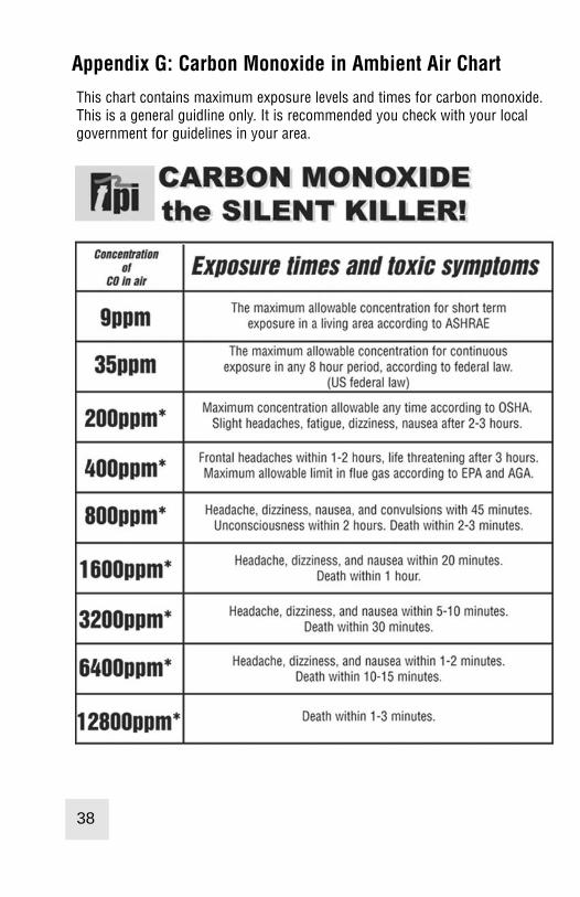
Appendix H: Battery Replacement
When the battery status indicator is empty the batteries should be changedimmediately. For optimum performance replace the batteries with 3 AA sizealkaline batteries. The procedure for replacing batteries is as follows:
1. Turn the analyzer over and locate the phillips head battery cover screw. Seepicture below.
2. Loosen the screw. Pull out on the screw to remove the battery cover.
3. Remove the old batteries and observing the polartiy markings in the batterycompartment, install the new batteries.
4. Re-install the battery cover by fitting the bottom part in first.
5. Tighten the battery cover screw.
Battery Cover
Battery Cover Screw
39
Appendix G: Carbon Monoxide in Ambient Air Chart
This chart contains maximum exposure levels and times for carbon monoxide.This is a general guidline only. It is recommended you check with your localgovernment for guidelines in your area.
38

Notes: Notes:

Notes: Notes:

Test Products International, Inc.9615 SW Allen Blvd., Ste. 104
Beaverton, OR 97005Tel: 503-520-9197 Fax: 503-520-1225
www.tpi-thevalueleader.com
Test Products International, Ltd.342 Bronte Road South, Unit #9Milton Ontario Canada L9T5B7
Tel: 905-693-8558 Fax: 905-693-0888