combined sm32
TRANSCRIPT
Number 32
Printed in U.S.A. 90-864261 NOVEMBER 2001
2001, Mercury Marine
4.3L MPI GASOLINE ENGINESN 0M322781 and ABOVE
�������
����
90-864261 NOVEMBER 2001 Page i
Notice
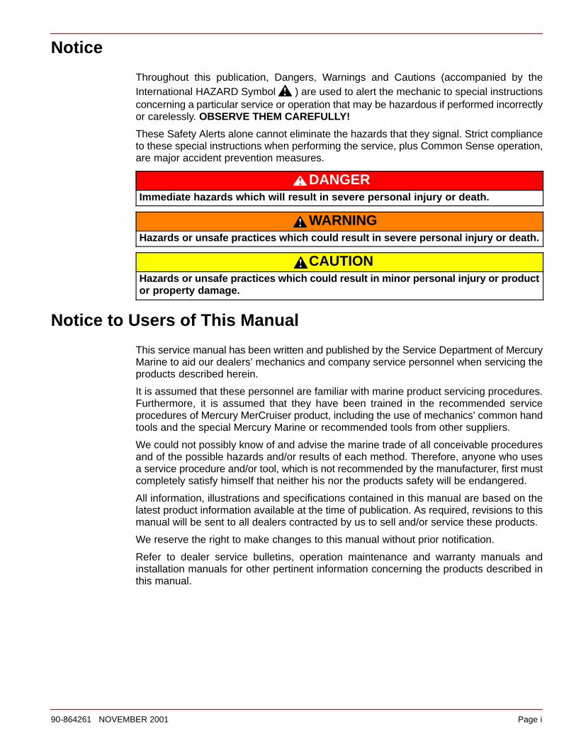
Throughout this publication, Dangers, Warnings and Cautions (accompanied by theInternational HAZARD Symbol ) are used to alert the mechanic to special instructionsconcerning a particular service or operation that may be hazardous if performed incorrectlyor carelessly. OBSERVE THEM CAREFULLY!
These Safety Alerts alone cannot eliminate the hazards that they signal. Strict complianceto these special instructions when performing the service, plus Common Sense operation,are major accident prevention measures.
DANGERImmediate hazards which will result in severe personal injury or death.
WARNINGHazards or unsafe practices which could result in severe personal injury or death.
CAUTIONHazards or unsafe practices which could result in minor personal injury or productor property damage.
Notice to Users of This Manual
This service manual has been written and published by the Service Department of MercuryMarine to aid our dealers’ mechanics and company service personnel when servicing theproducts described herein.
It is assumed that these personnel are familiar with marine product servicing procedures.Furthermore, it is assumed that they have been trained in the recommended serviceprocedures of Mercury MerCruiser product, including the use of mechanics’ common handtools and the special Mercury Marine or recommended tools from other suppliers.
We could not possibly know of and advise the marine trade of all conceivable proceduresand of the possible hazards and/or results of each method. Therefore, anyone who usesa service procedure and/or tool, which is not recommended by the manufacturer, first mustcompletely satisfy himself that neither his nor the products safety will be endangered.
All information, illustrations and specifications contained in this manual are based on thelatest product information available at the time of publication. As required, revisions to thismanual will be sent to all dealers contracted by us to sell and/or service these products.
We reserve the right to make changes to this manual without prior notification.
Refer to dealer service bulletins, operation maintenance and warranty manuals andinstallation manuals for other pertinent information concerning the products described inthis manual.
Page ii 90-864261 NOVEMBER 2001
PrecautionsIt should be kept in mind, while working on the product, that the electrical system and ignitionsystem are capable of violent and damaging short circuits or severe electrical shocks. Whenperforming any work where electrical terminals could possibly be grounded or touched bythe mechanic, the battery cables should be disconnected at the battery.
Any time the intake or exhaust openings are exposed during service they should be coveredto protect against accidental entrance of foreign material which could enter the cylinders andcause extensive internal damage when the engine is started.
It is important to note, during any maintenance procedure replacement fasteners must havethe same measurements and strength as those removed. Numbers on the heads of themetric bolts and on the surfaces of metric nuts indicate their strength. American bolts useradial lines for this purpose, while most American nuts do not have strength markings.Mismatched or incorrect fasteners can result in damage or malfunction, or possibly personalinjury. Therefore, fasteners removed should be saved for reuse in the same locationswhenever possible. Where the fasteners are not satisfactory for re-use, care should betaken to select a replacement that matches the original.
Engine Mechanical ComponentsMany of the engine mechanical components are designed for marine applications. Unlikeautomotive engines, marine engines are subjected to extended periods of heavy loadand wide open throttle operation and, therefore, require heavy-duty components. Specialmarine engine parts have design and manufacturing specifications that are required toprovide long life and dependable performance. Marine engine parts also must be able toresist the corrosive action of salt or brackish water that will rust or corrode standardautomotive parts within a short period of time.
Failure to use recommended Quicksilver service replacement parts can result in poorengine performance and/or durability, rapid corrosion of parts subjected to salt water andpossibly complete failure of the engine.
Replacement PartsUse of parts other than the recommended service replacement parts, will void the warrantyon those parts that are damaged as a result.
WARNINGElectrical, ignition and fuel system components on Mercury MerCruiser Enginesand Stern Drives are designed and manufactured to comply with U.S. Coast GuardRules and Regulations to minimize risks of fire or explosion.
Use of replacement electrical, ignition or fuel system components, which do notcomply to these rules and regulations, could result in a fire or explosion hazard andshould be avoided.
When servicing the electrical, ignition and fuel systems, it is extremely importantthat all components are properly installed and tightened. If not, any electrical orignition component opening would permit sparks to ignite fuel vapors from fuelsystem leaks, if they existed.
90-864261 NOVEMBER 2001 Page iii
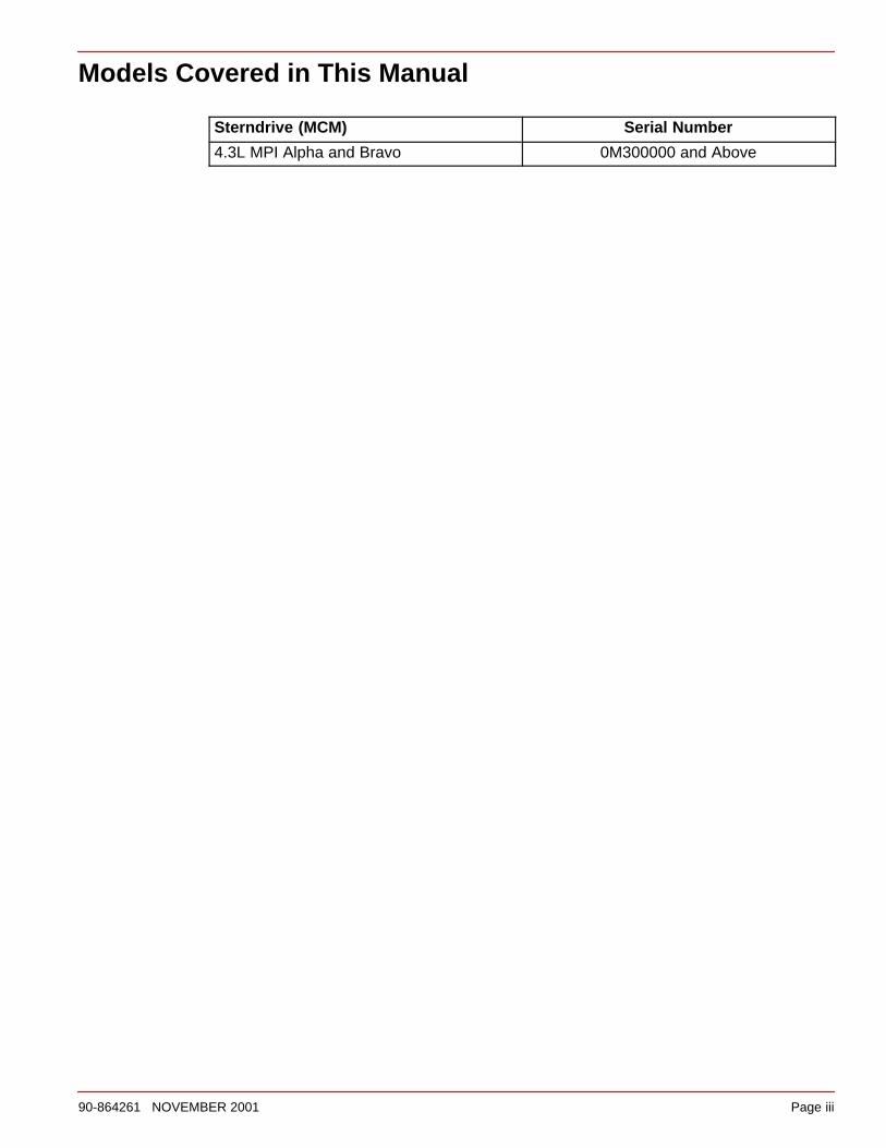
Models Covered in This Manual
Sterndrive (MCM) Serial Number
4.3L MPI Alpha and Bravo 0M300000 and Above
Page iv 90-864261 NOVEMBER 2001
THIS PAGE IS INTENTIONALLY BLANK
1
2
3
4
5
6
7
8
Important Information
Removal And Installation
Engine Mechanical
Electrical System
Fuel System
Cooling System
Exhaust System
Power Steering
90-864261 NOVEMBER 2001 Page v
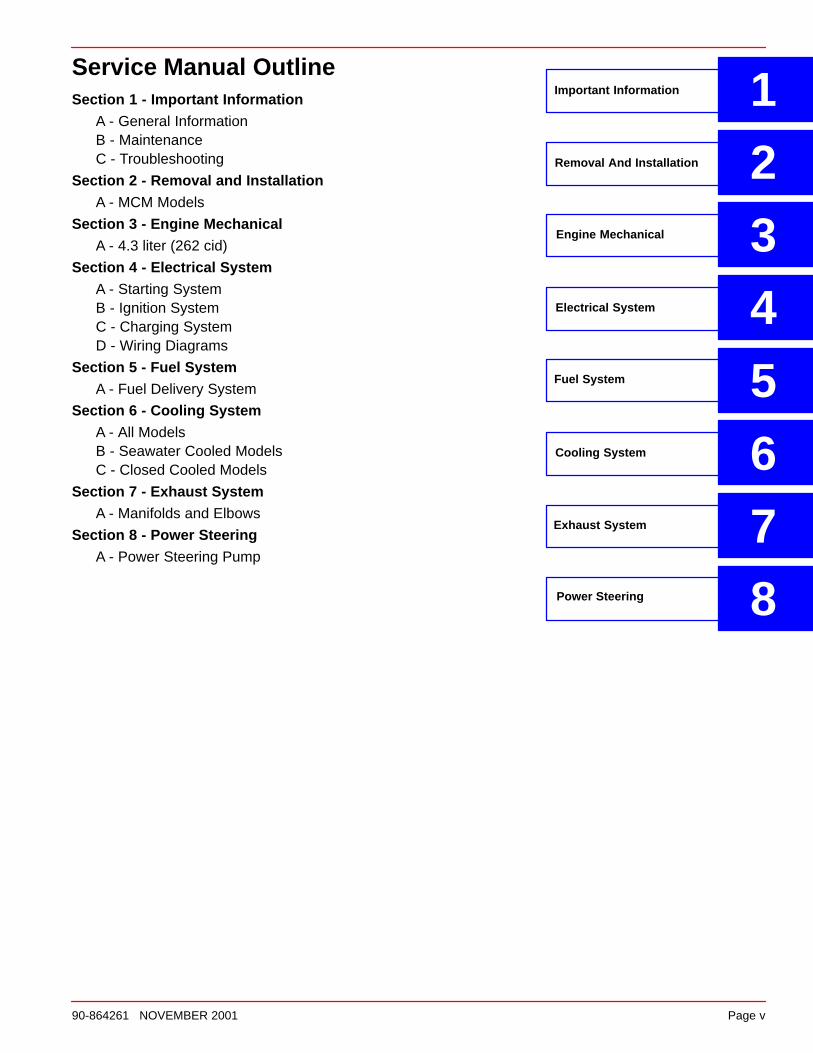
Service Manual OutlineSection 1 - Important Information
A - General InformationB - MaintenanceC - Troubleshooting
Section 2 - Removal and InstallationA - MCM Models
Section 3 - Engine MechanicalA - 4.3 liter (262 cid)
Section 4 - Electrical SystemA - Starting SystemB - Ignition SystemC - Charging SystemD - Wiring Diagrams
Section 5 - Fuel SystemA - Fuel Delivery System
Section 6 - Cooling SystemA - All ModelsB - Seawater Cooled ModelsC - Closed Cooled Models
Section 7 - Exhaust SystemA - Manifolds and Elbows
Section 8 - Power SteeringA - Power Steering Pump
Page vi 90-864261 NOVEMBER 2001
IMPORTANT INFORMATIONSection 1A - General Information
Introduction 1A-2. . . . . . . . . . . . . . . . . . . . . . . . . . . . How to Use This Manual 1A-2. . . . . . . . . . . . . . . . .
Page Numbering 1A-2. . . . . . . . . . . . . . . . . . . . Engine Serial Number Locations 1A-3. . . . . . . . . . Mercury/Quicksilver Lubricants, Sealants And Adhesives 1A-4. . . . . . . . . . . . . . . . . . . . . . . .
IMPORTANT INFORMATIONSection 1B - Maintenance
Torque Specifications 1B-2. . . . . . . . . . . . . . . . Special Tools 1B-2. . . . . . . . . . . . . . . . . . . . . . . Lubricants / Sealants / Adhesives 1B-3. . . . . Engine And Tune-Up Specifications 1B-4. . . .
MCM (Sterndrive) Models 1B-4. . . . . . . . . . Fluid Specifications 1B-5. . . . . . . . . . . . . . . . . .
Engines 1B-5. . . . . . . . . . . . . . . . . . . . . . . . . Sterndrives 1B-5. . . . . . . . . . . . . . . . . . . . . .
Maintenance Schedules 1B-6. . . . . . . . . . . . . . Maintenance Intervals 1B-6. . . . . . . . . . . . . Routine Maintenance 1B-7. . . . . . . . . . . . . Scheduled Maintenance 1B-8. . . . . . . . . .
Crankcase Oil 1B-10. . . . . . . . . . . . . . . . . . . . . . Overfilled Crankcase Oil 1B-11. . . . . . . . . . . Checking 1B-11. . . . . . . . . . . . . . . . . . . . . . . . Filling 1B-12. . . . . . . . . . . . . . . . . . . . . . . . . . . Changing Oil and Filter 1B-13. . . . . . . . . . . .
Flushing The Power Package - MCM 1B-15. . Sterndrive Water Pickups 1B-15. . . . . . . . . . Alternative Water Pickups 1B-17. . . . . . . . . .
Sterndrive Unit Oil 1B-19. . . . . . . . . . . . . . . . . . . Checking 1B-19. . . . . . . . . . . . . . . . . . . . . . . . Filling 1B-19. . . . . . . . . . . . . . . . . . . . . . . . . . . Changing 1B-20. . . . . . . . . . . . . . . . . . . . . . . .
Power Trim Pump Fluid 1B-22. . . . . . . . . . . . . . Checking 1B-22. . . . . . . . . . . . . . . . . . . . . . . . Filling 1B-22. . . . . . . . . . . . . . . . . . . . . . . . . . . Changing 1B-22. . . . . . . . . . . . . . . . . . . . . . . .
Power Steering Pump Fluid 1B-23. . . . . . . . . . . Checking 1B-23. . . . . . . . . . . . . . . . . . . . . . . . Filling and Bleeding 1B-24. . . . . . . . . . . . . . .
Water Inlets 1B-26. . . . . . . . . . . . . . . . . . . . . . . . Seawater Strainer 1B-26. . . . . . . . . . . . . . . .
Closed Cooling System 1B-27. . . . . . . . . . . . . . Checking Coolant Level 1B-27. . . . . . . . . . . Cleaning and Inspection 1B-27. . . . . . . . . . . Changing Coolant 1B-27. . . . . . . . . . . . . . . .
Anodes 1B-28. . . . . . . . . . . . . . . . . . . . . . . . . . . . Propeller Shaft 1B-31. . . . . . . . . . . . . . . . . . . . . . Power Package Surfaces 1B-32. . . . . . . . . . . . .
Painting Your Power Package 1B-32. . . . . . Battery 1B-33. . . . . . . . . . . . . . . . . . . . . . . . . . . . . Instruments 1B-33. . . . . . . . . . . . . . . . . . . . . . . . . Gimbal Ring / Steering Connection 1B-33. . . . Changing Water Separating Fuel Filter 1B-34. Steering System 1B-35. . . . . . . . . . . . . . . . . . . . Remote Control 1B-35. . . . . . . . . . . . . . . . . . . . . Sterndrive Components 1B-35. . . . . . . . . . . . . . Lubrication 1B-35. . . . . . . . . . . . . . . . . . . . . . . . .
Throttle Cable 1B-35. . . . . . . . . . . . . . . . . . . . Shift Cable 1B-36. . . . . . . . . . . . . . . . . . . . . . . Sterndrive Components 1B-36. . . . . . . . . . .
Continuity Circuit 1B-41. . . . . . . . . . . . . . . . . . . . MerCathode 1B-43. . . . . . . . . . . . . . . . . . . . . . . . Engine Mounts 1B-43. . . . . . . . . . . . . . . . . . . . . . Electrical System 1B-43. . . . . . . . . . . . . . . . . . . . Cleaning Flame Arrestor 1B-44. . . . . . . . . . . . . Serpentine Drive Belt 1B-45. . . . . . . . . . . . . . . .
Sterndrive Models 1B-45. . . . . . . . . . . . . . . . Inspection 1B-45. . . . . . . . . . . . . . . . . . . . . . . Replacing Belt and/or Adjusting Tension 1B-46. . . . . . . . . . . . . . . .
Exhaust System 1B-47. . . . . . . . . . . . . . . . . . . . . Seawater Pump 1B-47. . . . . . . . . . . . . . . . . . . . . Cold Weather And Extended Storage 1B-48. .
Preparing Your Power Package For Storage 1B-48. . . . . . . . . . . . . . . . . . . . .
Draining Instructions 1B-50. . . . . . . . . . . . . . . . . Identification 1B-51. . . . . . . . . . . . . . . . . . . . . Boat In The Water 1B-52. . . . . . . . . . . . . . . . Boat Out Of The Water 1B-56. . . . . . . . . . . . All Models 1B-59. . . . . . . . . . . . . . . . . . . . . . .
90-864261 NOVEMBER 2001 Page vii
IMPORTANT INFORMATIONSection 1C - Troubleshooting
Used Spark Plug Analysis 1C-2. . . . . . . . . . . . Normal Condition 1C-2. . . . . . . . . . . . . . . . . Chipped Insulator 1C-3. . . . . . . . . . . . . . . . . Wet Fouling (Oil Deposits) 1C-3. . . . . . . . . Cold Fouling 1C-4. . . . . . . . . . . . . . . . . . . . . Overheating 1C-4. . . . . . . . . . . . . . . . . . . . . . High Speed Glazing 1C-5. . . . . . . . . . . . . . . Scavenger Deposits 1C-5. . . . . . . . . . . . . . . Pre-Ignition Damage 1C-6. . . . . . . . . . . . . . Reversed Coil Polarity 1C-6. . . . . . . . . . . . . Splashed Deposits 1C-7. . . . . . . . . . . . . . . . Mechanical Damage 1C-7. . . . . . . . . . . . . .
Poor Boat Performance And/Or Poor Maneuverability 1C-8. . . . . . . . . . . . . . . . Improper Full Throttle Engine RPM 1C-10. . . . Engine Cranks Over But Will Not Start Or Starts Hard 1C-11. . . . . . . . . . . . . . . . . . . . . .
Important Information 1C-11. . . . . . . . . . . . . Engine Will Not Crank Over 1C-12. . . . . . . . . . .
Charging System Inoperative 1C-12. . . . . . . . . Noisy Alternator 1C-13. . . . . . . . . . . . . . . . . . . . . Instrumentation Malfunction 1C-13. . . . . . . . . . Radio Noise 1C-13. . . . . . . . . . . . . . . . . . . . . . . . Poor Fuel Economy 1C-14. . . . . . . . . . . . . . . . . Engine Runs Poorly at Idle 1C-15. . . . . . . . . . . Engine Runs Poorly At High RPM 1C-16. . . . . Engine Acceleration Is Poor 1C-17. . . . . . . . . . Troubleshooting with Vacuum Gauge 1C-17. . Engine Noise 1C-18. . . . . . . . . . . . . . . . . . . . . . .
Important Information 1C-18. . . . . . . . . . . . . Oil Pressure 1C-24. . . . . . . . . . . . . . . . . . . . . . . . Excessive Oil Consumption 1C-27. . . . . . . . . . . Water In The Engine 1C-28. . . . . . . . . . . . . . . . .
Important Information 1C-28. . . . . . . . . . . . . Engine Overheats (Mechanical) 1C-30. . . . . . . Power Steering 1C-33. . . . . . . . . . . . . . . . . . . . . Drain System Will Not Drain Or Drains Slowly 1C-35. . . . . . . . . . . . . . . . . . . . . . . . . . . .
REMOVAL AND INSTALLATIONSection 2A - MCM Models
Torque Specifications 2A-2. . . . . . . . . . . . . . . . Lubricants / Sealants / Adhesives 2A-3. . . . . Special Tools 2A-4. . . . . . . . . . . . . . . . . . . . . . . Removal 2A-5. . . . . . . . . . . . . . . . . . . . . . . . . . . Engine Installation 2A-8. . . . . . . . . . . . . . . . . . . Electrical Connections 2A-13. . . . . . . . . . . . . . .
EFI Electrical System Precautions 2A-13. . Installing Continuity Wire 2A-14. . . . . . . . . . Instrumentation Connections 2A-14. . . . . . . Trim Position Sender Connections 2A-15. . MerCathode Connections 2A-16. . . . . . . . . . Audio Warning Alarm Connections 2A-17. . Power Trim Pump Connections 2A-17. . . . .
Fluid Connections 2A-18. . . . . . . . . . . . . . . . . . . Fuel 2A-18. . . . . . . . . . . . . . . . . . . . . . . . . . . . . Gear Lube Monitor Hose 2A-19. . . . . . . . . . Power Steering Hoses 2A-20. . . . . . . . . . . . . Bravo Models and Alpha Seawater Cooled Models Using Sterndrive Water Pickups 2A-21. . . . Alpha or Bravo Models Using Alternative Water Pickups 2A-21. . . Coolant Recovery Bottle 2A-24. . . . . . . . . . .
Shift Cable Installation 2A-25. . . . . . . . . . . . . . . Alpha Models - Drive Unit Not Installed 2A-25. . . . . . . . . . . Bravo Models 2A-30. . . . . . . . . . . . . . . . . . . . Throttle Cable Installation and Adjustment 2A-35. . . . . . . . . . . . . . . . . . Battery Connection 2A-37. . . . . . . . . . . . . . . Engine Cover Installation 2A-37. . . . . . . . . .
Page viii 90-864261 NOVEMBER 2001
ENGINE MECHANICALSection 3A - 4.3 liter (262 cid)
Identification 3A-3. . . . . . . . . . . . . . . . . . . . . . . . General Specifications 3A-4. . . . . . . . . . . . . . .
4.3 liter (262 cid) 3A-4. . . . . . . . . . . . . . . . . Engine Specifications - 4.3 liter (262 cid) 3A-5
Cylinder Head 3A-5. . . . . . . . . . . . . . . . . . . . Cylinder Bore 3A-5. . . . . . . . . . . . . . . . . . . . Oil Pump 3A-5. . . . . . . . . . . . . . . . . . . . . . . . Piston Bore Clearance 3A-5. . . . . . . . . . . . Piston Rings 3A-6. . . . . . . . . . . . . . . . . . . . . Piston Pin 3A-6. . . . . . . . . . . . . . . . . . . . . . . Crankshaft 3A-7. . . . . . . . . . . . . . . . . . . . . . . Connecting Rod 3A-8. . . . . . . . . . . . . . . . . . Valve 3A-8. . . . . . . . . . . . . . . . . . . . . . . . . . . . Valve (continued) 3A-9. . . . . . . . . . . . . . . . . Camshaft 3A-10. . . . . . . . . . . . . . . . . . . . . . . . Timing Chain 3A-10. . . . . . . . . . . . . . . . . . . . . Flywheel 3A-10. . . . . . . . . . . . . . . . . . . . . . . . .
Torque Specifications 3A-11. . . . . . . . . . . . . . . . Special Tools 3A-15. . . . . . . . . . . . . . . . . . . . . . . Lubricants / Sealants / Adhesives 3A-16. . . . . Precautions 3A-18. . . . . . . . . . . . . . . . . . . . . . . . General Information 3A-19. . . . . . . . . . . . . . . . .
Repair Procedures 3A-19. . . . . . . . . . . . . . . . Special Notice 3A-19. . . . . . . . . . . . . . . . . . . . Engine Rotation 3A-19. . . . . . . . . . . . . . . . . . Crankcase Oil Dipstick Measurements 3A-20
Engine Mounts 3A-21. . . . . . . . . . . . . . . . . . . . . . Exploded Views 3A-21. . . . . . . . . . . . . . . . . .
Valve Cover 3A-22. . . . . . . . . . . . . . . . . . . . . . . . Removal 3A-22. . . . . . . . . . . . . . . . . . . . . . . . . Cleaning and Inspection 3A-22. . . . . . . . . . . Installation 3A-23. . . . . . . . . . . . . . . . . . . . . . .
Rocker Arm / Valve Pushrod 3A-24. . . . . . . . . . Removal 3A-24. . . . . . . . . . . . . . . . . . . . . . . . . Cleaning 3A-25. . . . . . . . . . . . . . . . . . . . . . . . . Inspection 3A-25. . . . . . . . . . . . . . . . . . . . . . . Installation 3A-26. . . . . . . . . . . . . . . . . . . . . . .
Valve Stem Oil Seal / Valve Spring - Cylinder Head Installed 3A-28. . . . . . . . . . . . . .
Exploded View 3A-28. . . . . . . . . . . . . . . . . . . Removal 3A-29. . . . . . . . . . . . . . . . . . . . . . . . . Installation 3A-30. . . . . . . . . . . . . . . . . . . . . . .
Intake Manifold Assembly 3A-33. . . . . . . . . . . . Exploded View 3A-33. . . . . . . . . . . . . . . . . . . Removal 3A-34. . . . . . . . . . . . . . . . . . . . . . . . . Cleaning 3A-35. . . . . . . . . . . . . . . . . . . . . . . . . Inspection 3A-35. . . . . . . . . . . . . . . . . . . . . . . Upper And Lower Intake Manifolds 3A-36. . Installation 3A-36. . . . . . . . . . . . . . . . . . . . . . .
Hydraulic Valve Lifters 3A-39. . . . . . . . . . . . . . . Exploded View 3A-39. . . . . . . . . . . . . . . . . . . Special Information 3A-39. . . . . . . . . . . . . . . Removal 3A-40. . . . . . . . . . . . . . . . . . . . . . . . . Cleaning 3A-41. . . . . . . . . . . . . . . . . . . . . . . . . Inspection 3A-41. . . . . . . . . . . . . . . . . . . . . . . Installation 3A-42. . . . . . . . . . . . . . . . . . . . . . .
Camshaft and Camshaft Bearings 3A-43. . . . . Measuring Camshaft Lobe Lift 3A-43. . . . . . Removal 3A-45. . . . . . . . . . . . . . . . . . . . . . . . . Cleaning 3A-49. . . . . . . . . . . . . . . . . . . . . . . . . Inspection 3A-50. . . . . . . . . . . . . . . . . . . . . . . Installation 3A-51. . . . . . . . . . . . . . . . . . . . . . .
Cylinder Head 3A-58. . . . . . . . . . . . . . . . . . . . . . Removal 3A-58. . . . . . . . . . . . . . . . . . . . . . . . . Disassembly 3A-59. . . . . . . . . . . . . . . . . . . . . Cleaning 3A-60. . . . . . . . . . . . . . . . . . . . . . . . . Inspection 3A-61. . . . . . . . . . . . . . . . . . . . . . . Repair 3A-66. . . . . . . . . . . . . . . . . . . . . . . . . . . Reassembly 3A-69. . . . . . . . . . . . . . . . . . . . . Installation 3A-73. . . . . . . . . . . . . . . . . . . . . . .
Oil Pan 3A-75. . . . . . . . . . . . . . . . . . . . . . . . . . . . Removal 3A-75. . . . . . . . . . . . . . . . . . . . . . . . . Cleaning 3A-76. . . . . . . . . . . . . . . . . . . . . . . . . Inspection 3A-76. . . . . . . . . . . . . . . . . . . . . . . Installation 3A-76. . . . . . . . . . . . . . . . . . . . . . .
Oil Pump 3A-78. . . . . . . . . . . . . . . . . . . . . . . . . . . Exploded View 3A-78. . . . . . . . . . . . . . . . . . . Removal 3A-79. . . . . . . . . . . . . . . . . . . . . . . . . Disassembly 3A-79. . . . . . . . . . . . . . . . . . . . . Cleaning 3A-80. . . . . . . . . . . . . . . . . . . . . . . . . Inspection 3A-81. . . . . . . . . . . . . . . . . . . . . . . Reassembly 3A-82. . . . . . . . . . . . . . . . . . . . . Installation 3A-84. . . . . . . . . . . . . . . . . . . . . . .
Crankshaft Balancer 3A-85. . . . . . . . . . . . . . . . . Removal 3A-85. . . . . . . . . . . . . . . . . . . . . . . . . Cleaning 3A-85. . . . . . . . . . . . . . . . . . . . . . . . . Inspection 3A-85. . . . . . . . . . . . . . . . . . . . . . . Installation 3A-86. . . . . . . . . . . . . . . . . . . . . . .
Front Cover Oil Seal 3A-88. . . . . . . . . . . . . . . . . Oil Seal Replacement Without Removing Front Cover 3A-88. . . .
Front Cover 3A-89. . . . . . . . . . . . . . . . . . . . . . . . Removal 3A-89. . . . . . . . . . . . . . . . . . . . . . . . . Cleaning and Inspection 3A-90. . . . . . . . . . . Installation 3A-90. . . . . . . . . . . . . . . . . . . . . . .
90-864261 NOVEMBER 2001 Page ix
Section 3A - Engine Mechanical (continued)Connecting Rod, Bearings and Piston Assembly 3A-92. . . . . . . . . . . . . . . .
Exploded View 3A-92. . . . . . . . . . . . . . . . . . . Removal 3A-93. . . . . . . . . . . . . . . . . . . . . . . . . Disassembly 3A-95. . . . . . . . . . . . . . . . . . . . . Cleaning 3A-95. . . . . . . . . . . . . . . . . . . . . . . . . Inspection 3A-96. . . . . . . . . . . . . . . . . . . . . . . Reassembly 3A-111. . . . . . . . . . . . . . . . . . . . . Installation 3A-114. . . . . . . . . . . . . . . . . . . . . . .
Crankshaft, Main Bearings and Engine Block 3A-118. . . . . . . . . . . . . . . . . . .
Exploded View 3A-118. . . . . . . . . . . . . . . . . . . Removal 3A-119. . . . . . . . . . . . . . . . . . . . . . . . . Cleaning 3A-123. . . . . . . . . . . . . . . . . . . . . . . . . Inspection 3A-125. . . . . . . . . . . . . . . . . . . . . . . Installation 3A-137. . . . . . . . . . . . . . . . . . . . . . .
Timing Chain And Sprockets 3A-147. . . . . . . . . . Removal 3A-147. . . . . . . . . . . . . . . . . . . . . . . . . Cleaning 3A-148. . . . . . . . . . . . . . . . . . . . . . . . . Inspection 3A-148. . . . . . . . . . . . . . . . . . . . . . . Reassembly 3A-148. . . . . . . . . . . . . . . . . . . . . Installation 3A-150. . . . . . . . . . . . . . . . . . . . . . .
Flywheel Housing 3A-151. . . . . . . . . . . . . . . . . . . Removal 3A-151. . . . . . . . . . . . . . . . . . . . . . . . . Cleaning 3A-152. . . . . . . . . . . . . . . . . . . . . . . . . Inspection 3A-152. . . . . . . . . . . . . . . . . . . . . . . Installation 3A-152. . . . . . . . . . . . . . . . . . . . . . .
Flywheel 3A-153. . . . . . . . . . . . . . . . . . . . . . . . . . . Removal 3A-153. . . . . . . . . . . . . . . . . . . . . . . . . Cleaning and Inspection 3A-154. . . . . . . . . . . Installation 3A-154. . . . . . . . . . . . . . . . . . . . . . .
Rear Oil Seal 3A-156. . . . . . . . . . . . . . . . . . . . . . . Removal 3A-156. . . . . . . . . . . . . . . . . . . . . . . . . Cleaning 3A-156. . . . . . . . . . . . . . . . . . . . . . . . . Inspection 3A-156. . . . . . . . . . . . . . . . . . . . . . . Installation 3A-157. . . . . . . . . . . . . . . . . . . . . . .
Rear Oil Seal Retainer 3A-159. . . . . . . . . . . . . . . Removal 3A-159. . . . . . . . . . . . . . . . . . . . . . . . . Cleaning 3A-159. . . . . . . . . . . . . . . . . . . . . . . . . Inspection 3A-159. . . . . . . . . . . . . . . . . . . . . . . Installation 3A-160. . . . . . . . . . . . . . . . . . . . . . .
Oil Filter By-Pass Valve and Block Adapter 3A-161. . . . . . . . . . . . . . . . . . . . . .
Exploded View 3A-161. . . . . . . . . . . . . . . . . . . Removal 3A-162. . . . . . . . . . . . . . . . . . . . . . . . . Cleaning 3A-163. . . . . . . . . . . . . . . . . . . . . . . . . Inspection 3A-163. . . . . . . . . . . . . . . . . . . . . . . Installation 3A-164. . . . . . . . . . . . . . . . . . . . . . .
Page x 90-864261 NOVEMBER 2001
ELECTRICAL SYSTEMSection 4A - Starting System
Identification 4A-2. . . . . . . . . . . . . . . . . . . . . . . . Replacement Parts Warning 4A-2. . . . . . . . . . Precautions 4A-2. . . . . . . . . . . . . . . . . . . . . . . . Typical Starting System Components 4A-3. . Positive Current Flow 4A-4. . . . . . . . . . . . . . . . Battery 4A-4. . . . . . . . . . . . . . . . . . . . . . . . . . . . .
Battery Cable Recommendations 4A-4. . . Delco PG260F1 Starter 4A-5. . . . . . . . . . . . . . Specifications 4A-5. . . . . . . . . . . . . . . . . . . . . . .
Starter Specifications 4A-5. . . . . . . . . . . . . . Torque Specifications 4A-5. . . . . . . . . . . . .
Lubricants / Sealants / Adhesives 4A-5. . . . . Description 4A-5. . . . . . . . . . . . . . . . . . . . . . . . .
Testing 4A-6. . . . . . . . . . . . . . . . . . . . . . . . . . Removal 4A-8. . . . . . . . . . . . . . . . . . . . . . . . . . .
Solenoid Switch 4A-9. . . . . . . . . . . . . . . . . . Inspection 4A-9. . . . . . . . . . . . . . . . . . . . . . . . . . Installation 4A-10. . . . . . . . . . . . . . . . . . . . . . . . .
ELECTRICAL SYSTEMSection 4B - Ignition System
Specifications 4B-2. . . . . . . . . . . . . . . . . . . . . . . . . Spark Plugs 4B-2. . . . . . . . . . . . . . . . . . . . . . . . Distributor 4B-2. . . . . . . . . . . . . . . . . . . . . . . . . Coil 4B-2. . . . . . . . . . . . . . . . . . . . . . . . . . . . . . . Firing Order 4B-2. . . . . . . . . . . . . . . . . . . . . . . .
Torque Specifications 4B-2. . . . . . . . . . . . . . . . . . Lubricants / Sealants / Adhesives 4B-3. . . . . . . Spark Plugs 4B-3. . . . . . . . . . . . . . . . . . . . . . . . . .
Removal 4B-3. . . . . . . . . . . . . . . . . . . . . . . . . . . Inspection 4B-3. . . . . . . . . . . . . . . . . . . . . . . . . Replacing 4B-4. . . . . . . . . . . . . . . . . . . . . . . . . .
Spark Plug Wires 4B-5. . . . . . . . . . . . . . . . . . . . . . Inspection 4B-5. . . . . . . . . . . . . . . . . . . . . . . . . Replacing 4B-5. . . . . . . . . . . . . . . . . . . . . . . . . .
Ignition Coil 4B-7. . . . . . . . . . . . . . . . . . . . . . . . . . . Removal 4B-7. . . . . . . . . . . . . . . . . . . . . . . . . . . Installation 4B-8. . . . . . . . . . . . . . . . . . . . . . . . .
Distributor 4B-9. . . . . . . . . . . . . . . . . . . . . . . . . . . . Removal 4B-9. . . . . . . . . . . . . . . . . . . . . . . . . . . Disassembly 4B-10. . . . . . . . . . . . . . . . . . . . . . Cleaning and Inspection 4B-12. . . . . . . . . . . . Reassembly 4B-12. . . . . . . . . . . . . . . . . . . . . . Installation 4B-13. . . . . . . . . . . . . . . . . . . . . . . .
ELECTRICAL SYSTEMSection 4C - Charging System
Delco Alternator 4C-2. . . . . . . . . . . . . . . . . . . . . Identification 4C-2. . . . . . . . . . . . . . . . . . . . . Replacement Parts Warning 4C-2. . . . . . . Specifications 4C-3. . . . . . . . . . . . . . . . . . . . Torque Specifications 4C-3. . . . . . . . . . . . . Special Tools 4C-3. . . . . . . . . . . . . . . . . . . . .
Precautions 4C-4. . . . . . . . . . . . . . . . . . . . . . . . EFI Electrical System Precautions 4C-4. .
Charging System Components 4C-5. . . . . . . . Periodic Maintenance 4C-5. . . . . . . . . . . . . . . .
Troubleshooting Tests (Alternator on Engine) 4C-5. . . . . . . . . . . . . . .
Charging System 4C-6. . . . . . . . . . . . . . . . . Resistance 4C-7. . . . . . . . . . . . . . . . . . . . . . . Circuitry 4C-9. . . . . . . . . . . . . . . . . . . . . . . . .
Removal 4C-11. . . . . . . . . . . . . . . . . . . . . . . . . . . Alternator 4C-11. . . . . . . . . . . . . . . . . . . . . . . . Alternator Bracket 4C-11. . . . . . . . . . . . . . . .
Installation 4C-12. . . . . . . . . . . . . . . . . . . . . . . . . Alternator Bracket 4C-12. . . . . . . . . . . . . . . . Alternator 4C-12. . . . . . . . . . . . . . . . . . . . . . . . Battery Isolator Diagram 4C-14. . . . . . . . . . .

90-864261 NOVEMBER 2001 Page xi
ELECTRICAL SYSTEMSection 4D - Wiring Diagrams
Instrumentation 4D-2. . . . . . . . . . . . . . . . . . . . . Single Station Installations - Typical 4D-2.
Power Trim System 4D-4. . . . . . . . . . . . . . . . . .
MerCathode System Wiring Diagram 4D-5. . Wiring Diagrams 4D-6. . . . . . . . . . . . . . . . . . . .
FUEL SYSTEMSection 5A - Fuel Delivery System
Specifications 5A-2. . . . . . . . . . . . . . . . . . . . . . . Torque Specifications 5A-2. . . . . . . . . . . . . . . . Special Tools 5A-3. . . . . . . . . . . . . . . . . . . . . . . Lubricants / Sealants / Adhesives 5A-3. . . . . Replacement Parts Warning 5A-3. . . . . . . . . . Abbreviations 5A-4. . . . . . . . . . . . . . . . . . . . . . . Precautions 5A-5. . . . . . . . . . . . . . . . . . . . . . . . Fuel Supply Connections 5A-5. . . . . . . . . . . . . Fuel Delivery System 5A-6. . . . . . . . . . . . . . . .
Recommendations 5A-6. . . . . . . . . . . . . . . . Exploded Views 5A-7. . . . . . . . . . . . . . . . . . . . .
Fuel Rail and Injectors 5A-7. . . . . . . . . . . . . Throttle Body 5A-8. . . . . . . . . . . . . . . . . . . . . Cool Fuel System 5A-9. . . . . . . . . . . . . . . . .
Fuel System Flow Diagrams 5A-10. . . . . . . . . . Sensor Locations 5A-11. . . . . . . . . . . . . . . . . . . . Fuel Pressure Relief Procedure 5A-13. . . . . . . Flame Arrestor 5A-13. . . . . . . . . . . . . . . . . . . . . .
Removal 5A-13. . . . . . . . . . . . . . . . . . . . . . . . . Cleaning and Inspection 5A-13. . . . . . . . . . . Installation 5A-13. . . . . . . . . . . . . . . . . . . . . . .
Throttle Body 5A-14. . . . . . . . . . . . . . . . . . . . . . . Removal 5A-14. . . . . . . . . . . . . . . . . . . . . . . . . Cleaning and Inspection 5A-16. . . . . . . . . . . Installation 5A-17. . . . . . . . . . . . . . . . . . . . . . .
Electronic Control Module (ECM) 5A-18. . . . . . Removal 5A-18. . . . . . . . . . . . . . . . . . . . . . . . . Cleaning and Inspection 5A-18. . . . . . . . . . . Installation 5A-18. . . . . . . . . . . . . . . . . . . . . . .
Water Separating Fuel Filter 5A-19. . . . . . . . . . Removal 5A-20. . . . . . . . . . . . . . . . . . . . . . . . . Installation 5A-20. . . . . . . . . . . . . . . . . . . . . . .
Cool Fuel System 5A-20. . . . . . . . . . . . . . . . . . . Removal 5A-20. . . . . . . . . . . . . . . . . . . . . . . . . Disassembly 5A-22. . . . . . . . . . . . . . . . . . . . . Reassembly 5A-24. . . . . . . . . . . . . . . . . . . . . Installation 5A-28. . . . . . . . . . . . . . . . . . . . . . .
Intake Manifold 5A-29. . . . . . . . . . . . . . . . . . . . . Removal 5A-29. . . . . . . . . . . . . . . . . . . . . . . . . Disassembly 5A-31. . . . . . . . . . . . . . . . . . . . . Cleaning and Inspection 5A-36. . . . . . . . . . . Assembly 5A-36. . . . . . . . . . . . . . . . . . . . . . . . Installation 5A-39. . . . . . . . . . . . . . . . . . . . . . .
Sensors 5A-43. . . . . . . . . . . . . . . . . . . . . . . . . . . . Manifold Air Pressure / Temperature (MAPT) Sensor 5A-43. . . . . . . . . . . . . . . . . . Throttle Position Sensor (TPS) 5A-44. . . . . Idle Air Control (IAC) Valve 5A-46. . . . . . . . . Knock Sensor 5A-47. . . . . . . . . . . . . . . . . . . . Oil Pressure Sensor 5A-48. . . . . . . . . . . . . . . Oil Pressure Switch 5A-49. . . . . . . . . . . . . . . Fuel Pump Relay 5A-50. . . . . . . . . . . . . . . . . Main Power Relay 5A-51. . . . . . . . . . . . . . . .
Page xii 90-864261 NOVEMBER 2001
COOLING SYSTEMSection 6A - All Models
Torque Specifications 6A-2. . . . . . . . . . . . . . . . Lubricants / Sealants / Adhesives 6A-2. . . . . Seawater Inlet Recommendations 6A-3. . . . .
Seacock (Seawater Inlet Valve) 6A-3. . . . . Seawater Strainer 6A-3. . . . . . . . . . . . . . . .
Seawater Pickups 6A-4. . . . . . . . . . . . . . . . . . . Through the Hull Mounted 6A-4. . . . . . . . . Transom Mounted 6A-6. . . . . . . . . . . . . . . .
Quicksilver Sea Strainer 6A-8. . . . . . . . . . . . . . Removal 6A-8. . . . . . . . . . . . . . . . . . . . . . . . . Cleaning and Inspection 6A-9. . . . . . . . . . . Installation 6A-10. . . . . . . . . . . . . . . . . . . . . . .
Auxiliary Hot Water Heater Installation 6A-11. Supply Hose Connection 6A-11. . . . . . . . . . Return Hose Connection 6A-12. . . . . . . . . . .
Seawater Pump 6A-12. . . . . . . . . . . . . . . . . . . . . Output Test 6A-12. . . . . . . . . . . . . . . . . . . . . . Removal 6A-14. . . . . . . . . . . . . . . . . . . . . . . . . Disassembly 6A-15. . . . . . . . . . . . . . . . . . . . . Cleaning and Inspection 6A-16. . . . . . . . . . . Reassembly 6A-16. . . . . . . . . . . . . . . . . . . . . Installation 6A-19. . . . . . . . . . . . . . . . . . . . . . .
Water Circulating Pump 6A-20. . . . . . . . . . . . . . Removal 6A-20. . . . . . . . . . . . . . . . . . . . . . . . . Cleaning and Inspection 6A-21. . . . . . . . . . . Installation 6A-22. . . . . . . . . . . . . . . . . . . . . . .
Water Distribution Housing 6A-23. . . . . . . . . . . Removal 6A-23. . . . . . . . . . . . . . . . . . . . . . . . . Cleaning And Inspection 6A-23. . . . . . . . . . . Installation 6A-23. . . . . . . . . . . . . . . . . . . . . . .
COOLING SYSTEMSection 6B - Seawater Cooled Models
Torque Specifications 6B-2. . . . . . . . . . . . . . . . Lubricants / Sealants / Adhesives 6B-2. . . . . Specifications 6B-2. . . . . . . . . . . . . . . . . . . . . . .
Seawater Cooling System Capacity 6B-2. Thermostat 6B-2. . . . . . . . . . . . . . . . . . . . . .
Flushing Seawater Cooling System 6B-3. . . . Thermostat 6B-3. . . . . . . . . . . . . . . . . . . . . . . . .
Removal 6B-3. . . . . . . . . . . . . . . . . . . . . . . . . Testing 6B-4. . . . . . . . . . . . . . . . . . . . . . . . . . Installation 6B-5. . . . . . . . . . . . . . . . . . . . . . .
Water Flow Diagrams 6B-6. . . . . . . . . . . . . . . . Seawater Cooled Models With An Engine Mounted Seawater Pump 6B-6Seawater Cooled Models Without An Engine Mounted Seawater Pump 6B-7
COOLING SYSTEMSection 6C - Closed Cooled Models
Torque Specifications 6C-2. . . . . . . . . . . . . . . . Lubricants / Sealants / Adhesives 6C-2. . . . . Specifications 6C-2. . . . . . . . . . . . . . . . . . . . . . .
Closed Cooling System Capacity 6C-2. . . Coolant Specification 6C-2. . . . . . . . . . . . . . Thermostat 6C-2. . . . . . . . . . . . . . . . . . . . . . Pressure Cap Rating 6C-2. . . . . . . . . . . . . .
Description 6C-3. . . . . . . . . . . . . . . . . . . . . . . . . Coolant Recommendations 6C-3. . . . . . . . . . . Maintaining Coolant Level 6C-4. . . . . . . . . . . . Pressure Cap Maintenance 6C-5. . . . . . . . . . . Testing Closed Cooling System 6C-6. . . . . . .
Testing Coolant for Alkalinity 6C-6. . . . . . . Pressure Testing System 6C-7. . . . . . . . . . Testing for Cylinder Head Gasket Leak 6C-9. . . . . . . . . . . . . . . . . . . . . Testing Pressure Cap 6C-10. . . . . . . . . . . . .
Thermostat 6C-12. . . . . . . . . . . . . . . . . . . . . . . . . Removal 6C-12. . . . . . . . . . . . . . . . . . . . . . . . . Testing 6C-12. . . . . . . . . . . . . . . . . . . . . . . . . . Installation 6C-14. . . . . . . . . . . . . . . . . . . . . . .
Heat Exchanger 6C-15. . . . . . . . . . . . . . . . . . . . . Testing 6C-15. . . . . . . . . . . . . . . . . . . . . . . . . . Removal 6C-15. . . . . . . . . . . . . . . . . . . . . . . . . Disassembly 6C-16. . . . . . . . . . . . . . . . . . . . . Cleaning And Inspection 6C-16. . . . . . . . . . . Repair 6C-16. . . . . . . . . . . . . . . . . . . . . . . . . . . Assembly 6C-17. . . . . . . . . . . . . . . . . . . . . . . . Installation 6C-18. . . . . . . . . . . . . . . . . . . . . . .
Heat Exchanger Bracket Hardware 6C-19. . . . Heat Exchanger Hose Connections 6C-20. . . . Closed Cooling System Water Flow Diagram 6C-21. . . . . . . . . . . . . . . . . . . . . . . . . . .
90-864261 NOVEMBER 2001 Page xiii
EXHAUST SYSTEMSection 7A - Manifolds, Elbows And Risers
Torque Specifications 7A-2. . . . . . . . . . . . . . . . . . Lubricants / Sealants / Adhesives 7A-2. . . . . . . Exploded View 7A-3. . . . . . . . . . . . . . . . . . . . . . . . Removal 7A-5. . . . . . . . . . . . . . . . . . . . . . . . . . . . .
Cleaning and Inspection 7A-6. . . . . . . . . . . . . . . . Manifold Leak Test 7A-7. . . . . . . . . . . . . . . . . . . . Installation 7A-7. . . . . . . . . . . . . . . . . . . . . . . . . . .
DRIVESSection 8A - Power Steering Pump
Torque Specifications 8A-2. . . . . . . . . . . . . . . . Lubricants / Sealants / Adhesives 8A-2. . . . . Special Tools 8A-2. . . . . . . . . . . . . . . . . . . . . . . Precautions 8A-3. . . . . . . . . . . . . . . . . . . . . . . . Power Steering Pump And ComponentsExploded View 8A-4. . . . . . . . . . . . . . . . . . . . . . Power Steering Pump Pulley Replacement 8A-5. . . . . . . . . . . . . . . . .
Removal 8A-5. . . . . . . . . . . . . . . . . . . . . . . . . Installation 8A-5. . . . . . . . . . . . . . . . . . . . . . .
Power Steering Pump 8A-6. . . . . . . . . . . . . . . . Removal 8A-6. . . . . . . . . . . . . . . . . . . . . . . . . Flow Control Valve Servicing 8A-7. . . . . . . Pump Shaft Oil Seal Replacement 8A-8. . Installation 8A-10. . . . . . . . . . . . . . . . . . . . . . .
Replacing Belt And/Or Adjusting Tension 8A-11Filling And Bleeding 8A-11. . . . . . . . . . . . . . . . . Checking Fluid Level 8A-11. . . . . . . . . . . . . . . . . Hydraulic Hoses And Fluid Cooler 8A-12. . . . .
High Pressure Hose (Pump-To-Control Valve) 8A-12. . . . . . . . . . Low Pressure Hose (Pump-To-Fluid Cooler) 8A-14. . . . . . . . . . . Low Pressure Hose (Control Valve-To-Fluid Cooler) 8A-16. . . .
1A
GENERAL INFORMATIONSERVICE MANUAL NUMBER 32
90-864261 NOVEMBER 2001 Page 1A-1
IMPORTANT INFORMATIONSection 1A - General Information
Table of Contents
Introduction 1A-2. . . . . . . . . . . . . . . . . . . . . . . . . . . . . How to Use This Manual 1A-2. . . . . . . . . . . . . . . . .
Page Numbering 1A-2. . . . . . . . . . . . . . . . . . . . . Engine Serial Number Locations 1A-3. . . . . . . . . . Mercury/Quicksilver Lubricants, Sealants And Adhesives 1A-4. . . . . . . . . . . . . . . . . . . . . . . . .
GENERAL INFORMATION SERVICE MANUAL NUMBER 32
Page 1A-2 90-864261 NOVEMBER 2001
Introduction
This comprehensive overhaul and repair manual is designed as a service guide for themodels previously listed. It provides specific information, including procedures fordisassembly, inspection, assembly and adjustment to enable dealers and servicemechanics to repair and tune these engines.
Before attempting repairs or tune-up, it is suggested that the procedure first be read throughto gain knowledge of the methods and tools used and the cautions and warnings requiredfor safety.
How To Use This Manual
This manual is divided into sections which represent major components and systems.
Some sections are further divided into parts that more fully describe the component.
Refer to the Service Manual Outline following Models Covered In This Manual for sectiontitles.
Page IdentificationThe service manual number and section title appear at the top of the page. Two numbergroups appear at the bottom of each page. Following is an example and a description.
a b c d e f g
a - Section Numberb - Section Partc - Page Numberd - Manual Numbere - Revision Numberf - Month Printedg - Year Printed
GENERAL INFORMATIONSERVICE MANUAL NUMBER 32
90-864261 NOVEMBER 2001 Page 1A-3
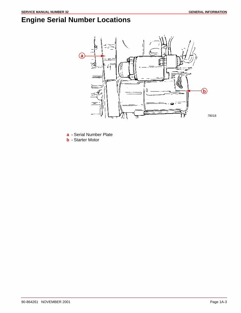
Engine Serial Number Locations
78018
a
b
a - Serial Number Plateb - Starter Motor
GENERAL INFORMATION SERVICE MANUAL NUMBER 32
Page 1A-4 90-864261 NOVEMBER 2001
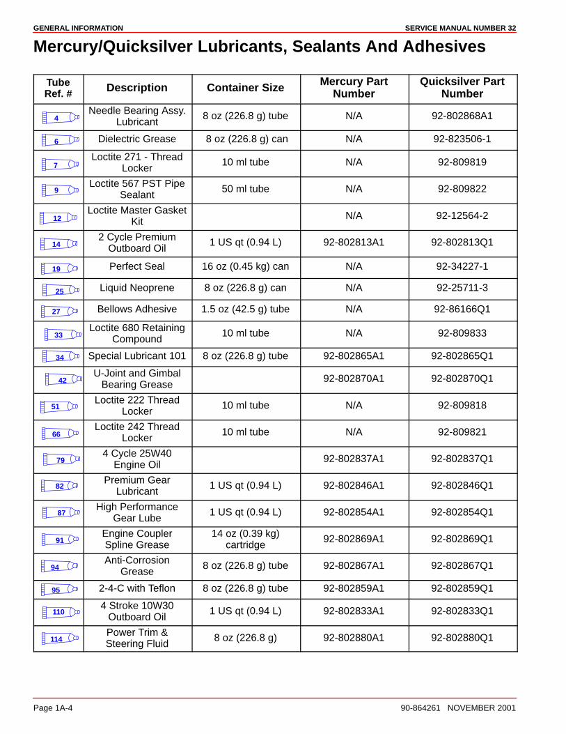
Mercury/Quicksilver Lubricants, Sealants And Adhesives
TubeRef. # Description Container Size Mercury Part
NumberQuicksilver Part
Number
4Needle Bearing Assy.
Lubricant8 oz (226.8 g) tube N/A 92-802868A1
6 Dielectric Grease 8 oz (226.8 g) can N/A 92-823506-1
7Loctite 271 - Thread
Locker10 ml tube N/A 92-809819
9Loctite 567 PST Pipe
Sealant50 ml tube N/A 92-809822
12Loctite Master Gasket
KitN/A 92-12564-2
142 Cycle Premium
Outboard Oil1 US qt (0.94 L) 92-802813A1 92-802813Q1
19 Perfect Seal 16 oz (0.45 kg) can N/A 92-34227-1
25 Liquid Neoprene 8 oz (226.8 g) can N/A 92-25711-3
27 Bellows Adhesive 1.5 oz (42.5 g) tube N/A 92-86166Q1
33Loctite 680 Retaining
Compound10 ml tube N/A 92-809833
34 Special Lubricant 101 8 oz (226.8 g) tube 92-802865A1 92-802865Q1
42U-Joint and Gimbal
Bearing Grease92-802870A1 92-802870Q1
51Loctite 222 Thread
Locker10 ml tube N/A 92-809818
66Loctite 242 Thread
Locker10 ml tube N/A 92-809821
794 Cycle 25W40
Engine Oil92-802837A1 92-802837Q1
82Premium Gear
Lubricant1 US qt (0.94 L) 92-802846A1 92-802846Q1
87High Performance
Gear Lube1 US qt (0.94 L) 92-802854A1 92-802854Q1
91Engine CouplerSpline Grease
14 oz (0.39 kg)cartridge
92-802869A1 92-802869Q1
94Anti-Corrosion
Grease8 oz (226.8 g) tube 92-802867A1 92-802867Q1
95 2-4-C with Teflon 8 oz (226.8 g) tube 92-802859A1 92-802859Q1
1104 Stroke 10W30
Outboard Oil1 US qt (0.94 L) 92-802833A1 92-802833Q1
114Power Trim &Steering Fluid
8 oz (226.8 g) 92-802880A1 92-802880Q1
GENERAL INFORMATIONSERVICE MANUAL NUMBER 32
90-864261 NOVEMBER 2001 Page 1A-5
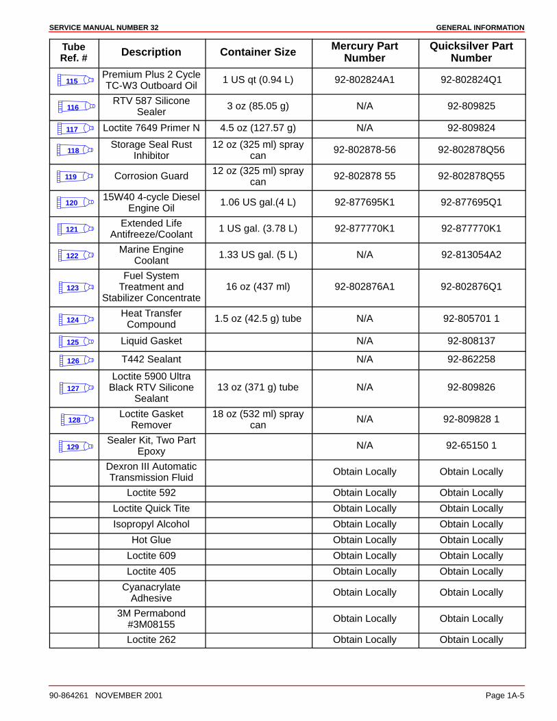
TubeRef. # Description Container Size Mercury Part
NumberQuicksilver Part
Number
115Premium Plus 2 CycleTC-W3 Outboard Oil
1 US qt (0.94 L) 92-802824A1 92-802824Q1
116RTV 587 Silicone
Sealer3 oz (85.05 g) N/A 92-809825
117 Loctite 7649 Primer N 4.5 oz (127.57 g) N/A 92-809824
118Storage Seal Rust
Inhibitor12 oz (325 ml) spray
can92-802878-56 92-802878Q56
119 Corrosion Guard 12 oz (325 ml) spraycan
92-802878 55 92-802878Q55
12015W40 4-cycle Diesel
Engine Oil1.06 US gal.(4 L) 92-877695K1 92-877695Q1
121Extended Life
Antifreeze/Coolant1 US gal. (3.78 L) 92-877770K1 92-877770K1
122Marine Engine
Coolant1.33 US gal. (5 L) N/A 92-813054A2
123
Fuel SystemTreatment and
Stabilizer Concentrate16 oz (437 ml) 92-802876A1 92-802876Q1
124Heat Transfer
Compound1.5 oz (42.5 g) tube N/A 92-805701 1
125 Liquid Gasket N/A 92-808137
126 T442 Sealant N/A 92-862258
127
Loctite 5900 UltraBlack RTV Silicone
Sealant13 oz (371 g) tube N/A 92-809826
128Loctite Gasket
Remover18 oz (532 ml) spray
canN/A 92-809828 1
129Sealer Kit, Two Part
EpoxyN/A 92-65150 1
Dexron III AutomaticTransmission Fluid
Obtain Locally Obtain Locally
Loctite 592 Obtain Locally Obtain Locally
Loctite Quick Tite Obtain Locally Obtain Locally
Isopropyl Alcohol Obtain Locally Obtain Locally
Hot Glue Obtain Locally Obtain Locally
Loctite 609 Obtain Locally Obtain Locally
Loctite 405 Obtain Locally Obtain Locally
CyanacrylateAdhesive
Obtain Locally Obtain Locally
3M Permabond#3M08155
Obtain Locally Obtain Locally
Loctite 262 Obtain Locally Obtain Locally
1B
MAINTENANCESERVICE MANUAL NUMBER 32
90-864261 NOVEMBER 2001 Page 1B-1
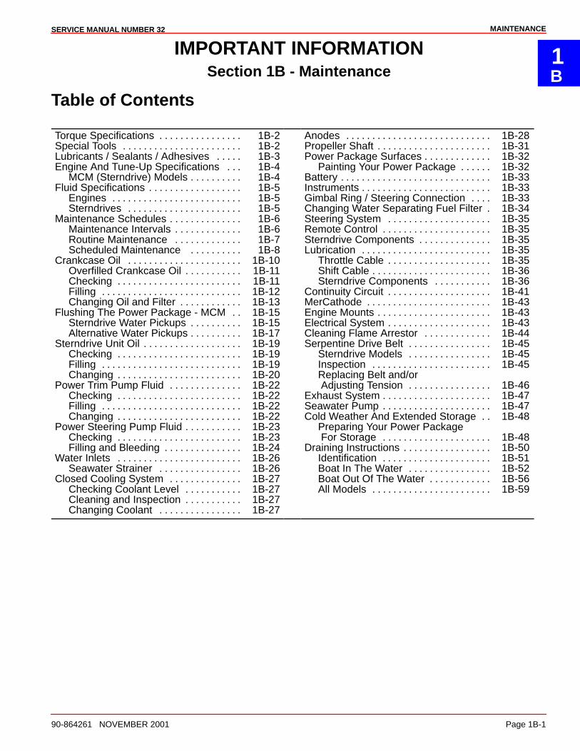
IMPORTANT INFORMATIONSection 1B - Maintenance
Table of Contents
Torque Specifications 1B-2. . . . . . . . . . . . . . . . Special Tools 1B-2. . . . . . . . . . . . . . . . . . . . . . . Lubricants / Sealants / Adhesives 1B-3. . . . . Engine And Tune-Up Specifications 1B-4. . .
MCM (Sterndrive) Models 1B-4. . . . . . . . . . Fluid Specifications 1B-5. . . . . . . . . . . . . . . . . .
Engines 1B-5. . . . . . . . . . . . . . . . . . . . . . . . . Sterndrives 1B-5. . . . . . . . . . . . . . . . . . . . . .
Maintenance Schedules 1B-6. . . . . . . . . . . . . . Maintenance Intervals 1B-6. . . . . . . . . . . . . Routine Maintenance 1B-7. . . . . . . . . . . . . Scheduled Maintenance 1B-8. . . . . . . . . .
Crankcase Oil 1B-10. . . . . . . . . . . . . . . . . . . . . . Overfilled Crankcase Oil 1B-11. . . . . . . . . . . Checking 1B-11. . . . . . . . . . . . . . . . . . . . . . . . Filling 1B-12. . . . . . . . . . . . . . . . . . . . . . . . . . . Changing Oil and Filter 1B-13. . . . . . . . . . . .
Flushing The Power Package - MCM 1B-15. . Sterndrive Water Pickups 1B-15. . . . . . . . . . Alternative Water Pickups 1B-17. . . . . . . . . .
Sterndrive Unit Oil 1B-19. . . . . . . . . . . . . . . . . . . Checking 1B-19. . . . . . . . . . . . . . . . . . . . . . . . Filling 1B-19. . . . . . . . . . . . . . . . . . . . . . . . . . . Changing 1B-20. . . . . . . . . . . . . . . . . . . . . . . .
Power Trim Pump Fluid 1B-22. . . . . . . . . . . . . . Checking 1B-22. . . . . . . . . . . . . . . . . . . . . . . . Filling 1B-22. . . . . . . . . . . . . . . . . . . . . . . . . . . Changing 1B-22. . . . . . . . . . . . . . . . . . . . . . . .
Power Steering Pump Fluid 1B-23. . . . . . . . . . . Checking 1B-23. . . . . . . . . . . . . . . . . . . . . . . . Filling and Bleeding 1B-24. . . . . . . . . . . . . . .
Water Inlets 1B-26. . . . . . . . . . . . . . . . . . . . . . . . Seawater Strainer 1B-26. . . . . . . . . . . . . . . .
Closed Cooling System 1B-27. . . . . . . . . . . . . . Checking Coolant Level 1B-27. . . . . . . . . . . Cleaning and Inspection 1B-27. . . . . . . . . . . Changing Coolant 1B-27. . . . . . . . . . . . . . . .
Anodes 1B-28. . . . . . . . . . . . . . . . . . . . . . . . . . . . Propeller Shaft 1B-31. . . . . . . . . . . . . . . . . . . . . . Power Package Surfaces 1B-32. . . . . . . . . . . . .
Painting Your Power Package 1B-32. . . . . . Battery 1B-33. . . . . . . . . . . . . . . . . . . . . . . . . . . . . Instruments 1B-33. . . . . . . . . . . . . . . . . . . . . . . . . Gimbal Ring / Steering Connection 1B-33. . . . Changing Water Separating Fuel Filter 1B-34. Steering System 1B-35. . . . . . . . . . . . . . . . . . . . Remote Control 1B-35. . . . . . . . . . . . . . . . . . . . . Sterndrive Components 1B-35. . . . . . . . . . . . . . Lubrication 1B-35. . . . . . . . . . . . . . . . . . . . . . . . .
Throttle Cable 1B-35. . . . . . . . . . . . . . . . . . . . Shift Cable 1B-36. . . . . . . . . . . . . . . . . . . . . . . Sterndrive Components 1B-36. . . . . . . . . . .
Continuity Circuit 1B-41. . . . . . . . . . . . . . . . . . . . MerCathode 1B-43. . . . . . . . . . . . . . . . . . . . . . . . Engine Mounts 1B-43. . . . . . . . . . . . . . . . . . . . . . Electrical System 1B-43. . . . . . . . . . . . . . . . . . . . Cleaning Flame Arrestor 1B-44. . . . . . . . . . . . . Serpentine Drive Belt 1B-45. . . . . . . . . . . . . . . .
Sterndrive Models 1B-45. . . . . . . . . . . . . . . . Inspection 1B-45. . . . . . . . . . . . . . . . . . . . . . . Replacing Belt and/or Adjusting Tension 1B-46. . . . . . . . . . . . . . . .
Exhaust System 1B-47. . . . . . . . . . . . . . . . . . . . . Seawater Pump 1B-47. . . . . . . . . . . . . . . . . . . . . Cold Weather And Extended Storage 1B-48. .
Preparing Your Power Package For Storage 1B-48. . . . . . . . . . . . . . . . . . . . .
Draining Instructions 1B-50. . . . . . . . . . . . . . . . . Identification 1B-51. . . . . . . . . . . . . . . . . . . . . Boat In The Water 1B-52. . . . . . . . . . . . . . . . Boat Out Of The Water 1B-56. . . . . . . . . . . . All Models 1B-59. . . . . . . . . . . . . . . . . . . . . . .
MAINTENANCE SERVICE MANUAL NUMBER 32
Page 1B-2 90-864261 NOVEMBER 2001
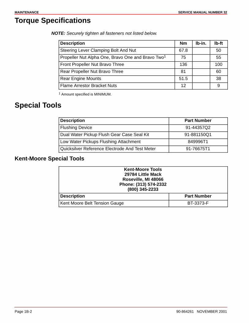
Torque Specifications
NOTE: Securely tighten all fasteners not listed below.
Description Nm lb-in. lb-ft
Steering Lever Clamping Bolt And Nut 67.8 50
Propeller Nut Alpha One, Bravo One and Bravo Two1 75 55
Front Propeller Nut Bravo Three 136 100
Rear Propeller Nut Bravo Three 81 60
Rear Engine Mounts 51.5 38
Flame Arrestor Bracket Nuts 12 9
1 Amount specified is MINIMUM.
Special Tools
Description Part Number
Flushing Device 91-44357Q2
Dual Water Pickup Flush Gear Case Seal Kit 91-881150Q1
Low Water Pickups Flushing Attachment 849996T1
Quicksilver Reference Electrode And Test Meter 91-76675T1
Kent-Moore Special Tools
Kent-Moore Tools29784 Little Mack
Roseville, MI 48066Phone: (313) 574-2332
(800) 345-2233
Description Part Number
Kent Moore Belt Tension Gauge BT-3373-F
MAINTENANCESERVICE MANUAL NUMBER 32
90-864261 NOVEMBER 2001 Page 1B-3
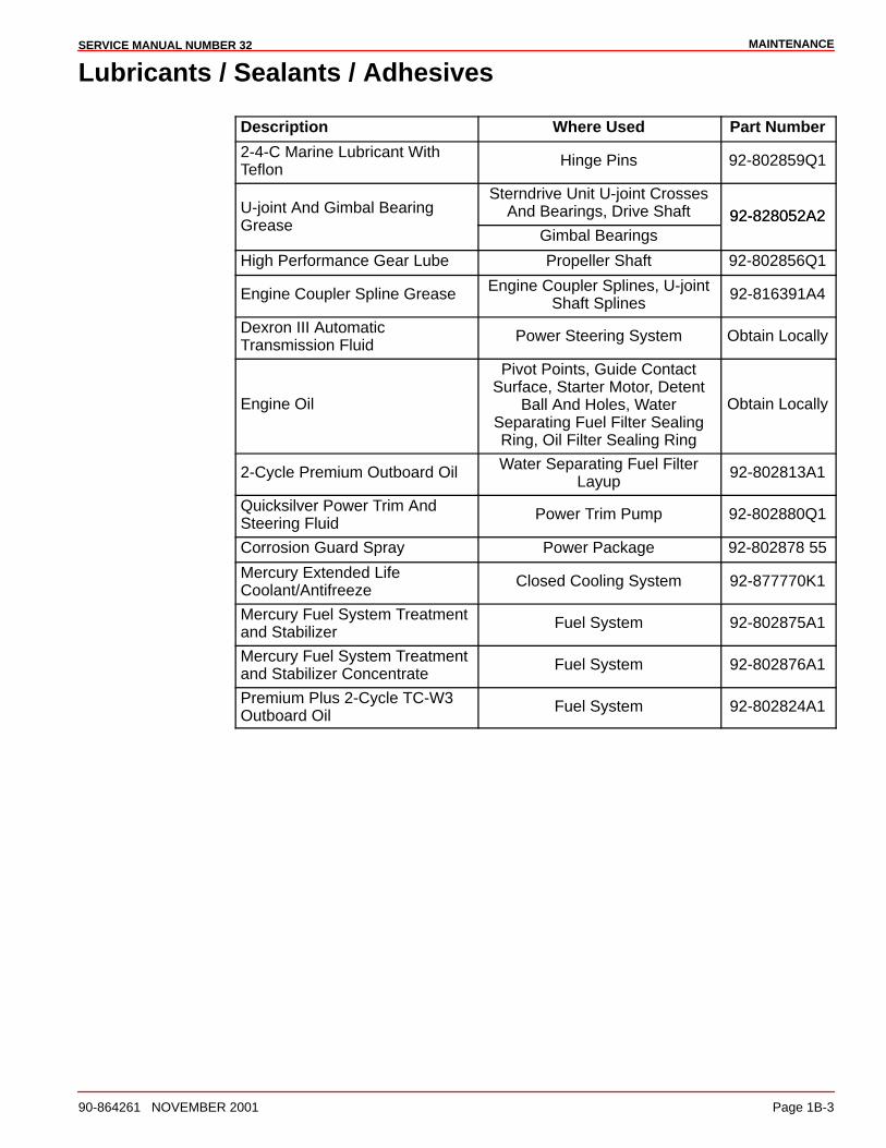
Lubricants / Sealants / Adhesives
Description Where Used Part Number
2-4-C Marine Lubricant WithTeflon
Hinge Pins 92-802859Q1
U-joint And Gimbal BearingSterndrive Unit U-joint Crosses
And Bearings, Drive Shaft 92-828052A2Grease
Gimbal Bearings92-828052A2
High Performance Gear Lube Propeller Shaft 92-802856Q1
Engine Coupler Spline Grease Engine Coupler Splines, U-jointShaft Splines
92-816391A4
Dexron III AutomaticTransmission Fluid
Power Steering System Obtain Locally
Engine Oil
Pivot Points, Guide ContactSurface, Starter Motor, Detent
Ball And Holes, WaterSeparating Fuel Filter SealingRing, Oil Filter Sealing Ring
Obtain Locally
2-Cycle Premium Outboard Oil Water Separating Fuel FilterLayup
92-802813A1
Quicksilver Power Trim AndSteering Fluid
Power Trim Pump 92-802880Q1
Corrosion Guard Spray Power Package 92-802878 55
Mercury Extended LifeCoolant/Antifreeze
Closed Cooling System 92-877770K1
Mercury Fuel System Treatmentand Stabilizer
Fuel System 92-802875A1
Mercury Fuel System Treatmentand Stabilizer Concentrate
Fuel System 92-802876A1
Premium Plus 2-Cycle TC-W3Outboard Oil
Fuel System 92-802824A1
MAINTENANCE SERVICE MANUAL NUMBER 32
Page 1B-4 90-864261 NOVEMBER 2001
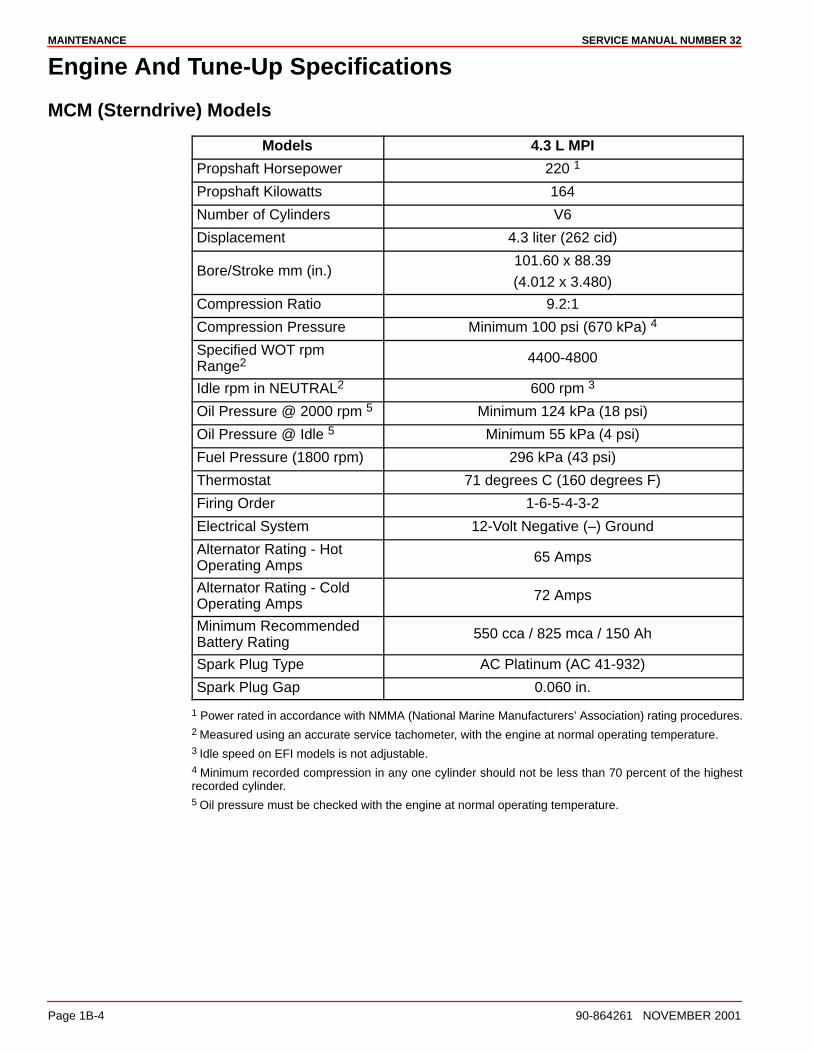
Engine And Tune-Up Specifications
MCM (Sterndrive) Models
Models 4.3 L MPI
Propshaft Horsepower 220 1
Propshaft Kilowatts 164
Number of Cylinders V6
Displacement 4.3 liter (262 cid)
Bore/Stroke mm (in.)101.60 x 88.39
(4.012 x 3.480)
Compression Ratio 9.2:1
Compression Pressure Minimum 100 psi (670 kPa) 4
Specified WOT rpmRange2 4400-4800
Idle rpm in NEUTRAL2 600 rpm 3
Oil Pressure @ 2000 rpm 5 Minimum 124 kPa (18 psi)
Oil Pressure @ Idle 5 Minimum 55 kPa (4 psi)
Fuel Pressure (1800 rpm) 296 kPa (43 psi)
Thermostat 71 degrees C (160 degrees F)
Firing Order 1-6-5-4-3-2
Electrical System 12-Volt Negative (–) Ground
Alternator Rating - HotOperating Amps
65 Amps
Alternator Rating - ColdOperating Amps
72 Amps
Minimum RecommendedBattery Rating
550 cca / 825 mca / 150 Ah
Spark Plug Type AC Platinum (AC 41-932)
Spark Plug Gap 0.060 in.
1 Power rated in accordance with NMMA (National Marine Manufacturers’ Association) rating procedures.2 Measured using an accurate service tachometer, with the engine at normal operating temperature.3 Idle speed on EFI models is not adjustable.4 Minimum recorded compression in any one cylinder should not be less than 70 percent of the highestrecorded cylinder.5 Oil pressure must be checked with the engine at normal operating temperature.
MAINTENANCESERVICE MANUAL NUMBER 32
90-864261 NOVEMBER 2001 Page 1B-5
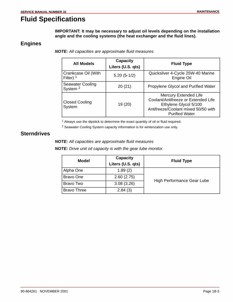
Fluid Specifications
IMPORTANT: It may be necessary to adjust oil levels depending on the installationangle and the cooling systems (the heat exchanger and the fluid lines).
EnginesNOTE: All capacities are approximate fluid measures
All ModelsCapacity
Liters (U.S. qts)Fluid Type
Crankcase Oil (WithFilter) 1
5.20 (5-1/2) Quicksilver 4-Cycle 25W-40 MarineEngine Oil
Seawater CoolingSystem 2
20 (21) Propylene Glycol and Purified Water
Closed CoolingSystem
19 (20)
Mercury Extended LifeCoolant/Antifreeze or Extended Life
Ethylene Glycol 5/100Antifreeze/Coolant mixed 50/50 with
Purified Water
1 Always use the dipstick to determine the exact quantity of oil or fluid required.2 Seawater Cooling System capacity information is for winterization use only.
SterndrivesNOTE: All capacities are approximate fluid measures
NOTE: Drive unit oil capacity is with the gear lube monitor.
ModelCapacity
Liters (U.S. qts)Fluid Type
Alpha One 1.89 (2)
Bravo One 2.60 (2.75)
Bravo Two 3.08 (3.26)High Performance Gear Lube
Bravo Three 2.84 (3)

MAINTENANCE SERVICE MANUAL NUMBER 32
Page 1B-6 90-864261 NOVEMBER 2001
Maintenance Schedules
NOTE: Only perform maintenance which applies to your particular power package.
Maintenance IntervalsMaintenance intervals and the corresponding tasks to be performed, as shown in thiscurrent schedule or as found in a previously printed schedule, are generally based on anaverage boating application and environment. However, individual operating habits andpersonal maintenance preferences can have an impact on the suggested intervals. Inconsideration of these factors, Mercury MerCruiser has adjusted some maintenanceintervals and the corresponding tasks to be performed. In some cases, this may allow formore individual tasks in a single visit to the servicing dealer. Therefore, it is very importantthat the boat owner and the servicing dealer discuss the current Maintenance Schedule anddevelop appropriate maintenance intervals to coincide with the individual operating habits,the environment and the maintenance requirements.
CAUTIONAlways disconnect the battery cables from the battery before working aroundelectrical systems components to prevent injury to yourself and damage to theelectrical system should a wire be accidentally shorted.
MAINTENANCESERVICE MANUAL NUMBER 32
90-864261 NOVEMBER 2001 Page 1B-7
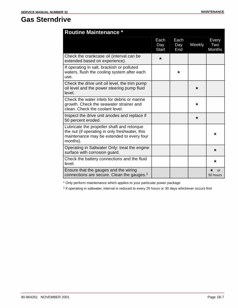
Gas Sterndrive
Routine Maintenance *EachDayStart
EachDayEnd
WeeklyEveryTwo
Months
Check the crankcase oil (interval can beextended based on experience).
�
If operating in salt, brackish or pollutedwaters, flush the cooling system after eachuse.
�
Check the drive unit oil level, the trim pumpoil level and the power steering pump fluidlevel.
�
Check the water inlets for debris or marinegrowth. Check the seawater strainer andclean. Check the coolant level.
�
Inspect the drive unit anodes and replace if50 percent eroded.
�
Lubricate the propeller shaft and retorquethe nut (if operating in only freshwater, thismaintenance may be extended to every fourmonths).
�
Operating in Saltwater Only: treat the enginesurface with corrosion guard.
�
Check the battery connections and the fluidlevel.
�
Ensure that the gauges and the wiringconnections are secure. Clean the gauges.1
� or50 hours
* Only perform maintenance which applies to your particular power package1 If operating in saltwater, interval is reduced to every 25 hours or 30 days whichever occurs first
MAINTENANCE SERVICE MANUAL NUMBER 32
Page 1B-8 90-864261 NOVEMBER 2001
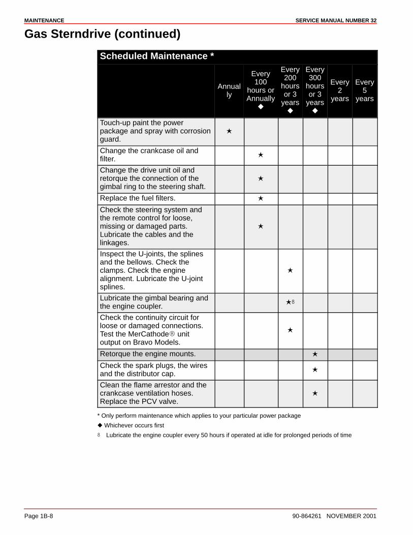
Gas Sterndrive (continued)
Scheduled Maintenance *
Annually
Every100
hours orAnnually
�
Every200
hoursor 3
years�
Every300
hoursor 3
years�
Every2
years
Every5
years
Touch-up paint the powerpackage and spray with corrosionguard.
�
Change the crankcase oil andfilter.
�
Change the drive unit oil andretorque the connection of thegimbal ring to the steering shaft.
�
Replace the fuel filters. �
Check the steering system andthe remote control for loose,missing or damaged parts.Lubricate the cables and thelinkages.
�
Inspect the U-joints, the splinesand the bellows. Check theclamps. Check the enginealignment. Lubricate the U-jointsplines.
�
Lubricate the gimbal bearing andthe engine coupler.
��
Check the continuity circuit forloose or damaged connections.Test the MerCathode� unitoutput on Bravo Models.
�
Retorque the engine mounts. �
Check the spark plugs, the wiresand the distributor cap.
�
Clean the flame arrestor and thecrankcase ventilation hoses.Replace the PCV valve.
�
* Only perform maintenance which applies to your particular power package
� Whichever occurs first
� Lubricate the engine coupler every 50 hours if operated at idle for prolonged periods of time
MAINTENANCESERVICE MANUAL NUMBER 32
90-864261 NOVEMBER 2001 Page 1B-9
Gas Sterndrive (continued)
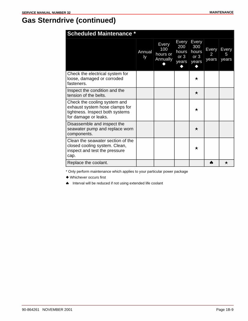
Scheduled Maintenance *
Annually
Every100
hours orAnnually
�
Every200
hoursor 3
years�
Every300
hoursor 3
years�
Every2
years
Every5
years
Check the electrical system forloose, damaged or corrodedfasteners.
�
Inspect the condition and thetension of the belts.
�
Check the cooling system andexhaust system hose clamps fortightness. Inspect both systemsfor damage or leaks.
�
Disassemble and inspect theseawater pump and replace worncomponents.
�
Clean the seawater section of theclosed cooling system. Clean,inspect and test the pressurecap.
�
Replace the coolant. � �
* Only perform maintenance which applies to your particular power package
� Whichever occurs first
� Interval will be reduced if not using extended life coolant

MAINTENANCE SERVICE MANUAL NUMBER 32
Page 1B-10 90-864261 NOVEMBER 2001
Crankcase Oil
To help obtain optimum engine performance and to provide maximum protection, westrongly recommend the use of Quicksilver 4-Cycle 25W-40 Marine Engine Oil. This oil isa special blend of 25-weight and 40-weight oils for marine engines. If not available, a goodgrade, straight weight, detergent automotive oil of the correct viscosity, with an APIclassification of SH, CF/CF-2, may be used.
In those areas where Quicksilver 4-Cycle 25W-40 Marine Engine Oil or a recommendedstraight weight oil are not available, a multi-viscosity 20W-40 or, as a second but lesspreferable choice, 20W-50, with API service ratings of SH, CF/CF-2 may be used.
IMPORTANT: The use of non-detergent oils, multi-viscosity oils (other thanQuicksilver 25W-40 or a good quality 20W-40 or 20W-50), synthetic oils, low qualityoils or oils that contain solid additives are specifically not recommended.
The chart below is a guide to crankcase oil selection. The oil filter should always be changedwhen changing the engine oil.
CAUTIONMercury MerCruiser or Quicksilver 4-Cycle oil is recommended for use for your en-gine. Severe engine damage may result from the use of an inferior oil.
75796
Quicksilver 4-Cycle 25W-40 Marine Engine Oil
SAE 20W
SAE 30W
SAE 40W
32° F0° C
50° F10° C
AIR TEMPERATURE
MAINTENANCESERVICE MANUAL NUMBER 32
90-864261 NOVEMBER 2001 Page 1B-11
Overfilled Crankcase OilAn overfilled crankcase (oil level being too high) can cause a fluctuation or drop in oilpressure and rocker arm clatter on Mercury MerCruiser engines. This condition results inthe engine crankshaft splashing and agitating the oil, causing it to foam (become aerated).The aerated oil causes the hydraulic valve lifters to bleed down. This, in turn, results inrocker arm clatter and loss of engine performance, due to the valves not opening properly.
Care must be taken when checking the engine oil level. The oil level must be maintainedbetween the ADD mark and the FULL or OK RANGE mark on the dipstick. To ensure thatyou are not getting a false reading, ensure the following:
• Boat at rest in the water, or
• If the boat is on a trailer, raise or lower the bow until the boat is setting at theapproximate angle that it would be if setting at rest in the water.
• Allow sufficient time for the oil to drain into the crankcase if the engine has just beenoperated or oil has just been added.
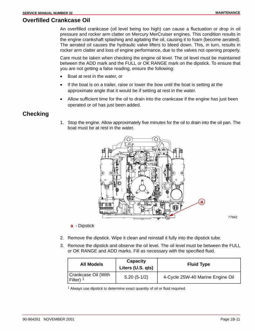
Checking1. Stop the engine. Allow approximately five minutes for the oil to drain into the oil pan. The
boat must be at rest in the water.
77942
a
a - Dipstick
2. Remove the dipstick. Wipe it clean and reinstall it fully into the dipstick tube.
3. Remove the dipstick and observe the oil level. The oil level must be between the FULLor OK RANGE and ADD marks. Fill as necessary with the specified fluid.
All ModelsCapacity
Liters (U.S. qts)Fluid Type
Crankcase Oil (WithFilter) 1
5.20 (5-1/2) 4-Cycle 25W-40 Marine Engine Oil
1 Always use dipstick to determine exact quantity of oil or fluid required.
MAINTENANCE SERVICE MANUAL NUMBER 32
Page 1B-12 90-864261 NOVEMBER 2001
Filling
CAUTIONENVIRONMENTAL HAZARD! Discharge of oil or oil waste into the environment isrestricted by law. Do not spill oil or oil waste into the environment when using orservicing your boat. Contain and dispose of oil or oil waste as defined by localauthorities.
IMPORTANT: Do NOT overfill the crankcase with oil.
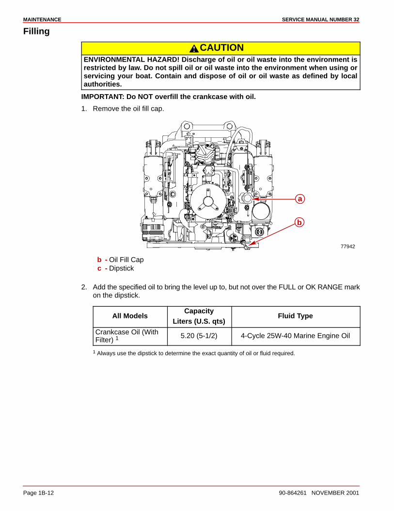
1. Remove the oil fill cap.
77942
a
b
b - Oil Fill Capc - Dipstick
2. Add the specified oil to bring the level up to, but not over the FULL or OK RANGE markon the dipstick.
All ModelsCapacity
Liters (U.S. qts)Fluid Type
Crankcase Oil (WithFilter) 1
5.20 (5-1/2) 4-Cycle 25W-40 Marine Engine Oil
1 Always use the dipstick to determine the exact quantity of oil or fluid required.

MAINTENANCESERVICE MANUAL NUMBER 32
90-864261 NOVEMBER 2001 Page 1B-13
Changing Oil and FilterRefer to the Maintenance schedule for the change interval. The crankcase oil should bechanged before placing the boat in storage.
IMPORTANT: Change the crankcase oil when the engine is warm from operation.Warm oil flows more freely, carrying away more impurities. Use only therecommended engine oil (refer to Specifications).
QUICK DRAIN OIL
1. Pull the tether through the bilge drain.
2. Place the oil drain hose in a suitable container.
3. Remove the drain plug from the oil drain hose.
4. After the oil has drained completely, install the drain plug in the oil drain hose.
5. Push the hose through the bilge drain and install the plug.
6. Proceed to ALL MODELS.
CRANKCASE OIL PUMP
1. Remove the dipstick.
2. Insert the hose end of the crankcase oil pump onto an appropriate container and usingthe handle, pump until the crankcase is empty.
70571
a
b
a - Crankcase Oil Pumpb - Dipstick
3. Remove the pump.
4. Install the dipstick.
5. Proceed to ALL MODELS.
MAINTENANCE SERVICE MANUAL NUMBER 32
Page 1B-14 90-864261 NOVEMBER 2001
ALL MODELS
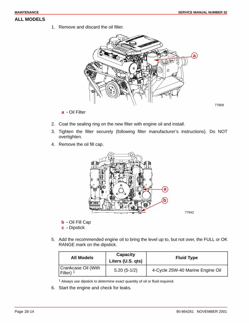
1. Remove and discard the oil filter.
77808
a
a - Oil Filter
2. Coat the sealing ring on the new filter with engine oil and install.
3. Tighten the filter securely (following filter manufacturer’s instructions). Do NOTovertighten.
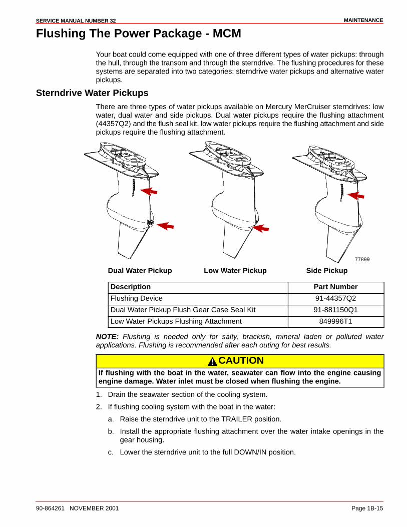
4. Remove the oil fill cap.
77942
a
b
b - Oil Fill Capc - Dipstick
5. Add the recommended engine oil to bring the level up to, but not over, the FULL or OKRANGE mark on the dipstick.
All ModelsCapacity
Liters (U.S. qts)Fluid Type
Crankcase Oil (WithFilter) 1
5.20 (5-1/2) 4-Cycle 25W-40 Marine Engine Oil
1 Always use dipstick to determine exact quantity of oil or fluid required.
6. Start the engine and check for leaks.
MAINTENANCESERVICE MANUAL NUMBER 32
90-864261 NOVEMBER 2001 Page 1B-15
Flushing The Power Package - MCM
Your boat could come equipped with one of three different types of water pickups: throughthe hull, through the transom and through the sterndrive. The flushing procedures for thesesystems are separated into two categories: sterndrive water pickups and alternative waterpickups.
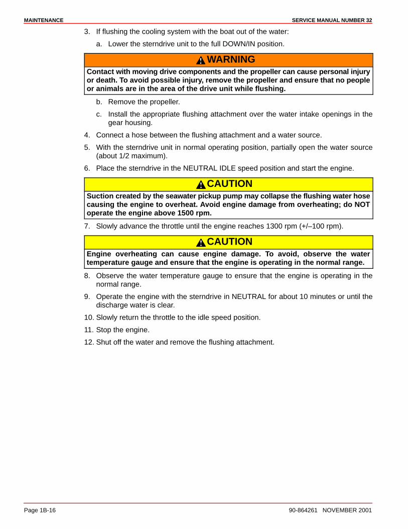
Sterndrive Water PickupsThere are three types of water pickups available on Mercury MerCruiser sterndrives: lowwater, dual water and side pickups. Dual water pickups require the flushing attachment(44357Q2) and the flush seal kit, low water pickups require the flushing attachment and sidepickups require the flushing attachment.
77899
Dual Water Pickup Low Water Pickup Side Pickup
Description Part Number
Flushing Device 91-44357Q2
Dual Water Pickup Flush Gear Case Seal Kit 91-881150Q1
Low Water Pickups Flushing Attachment 849996T1
NOTE: Flushing is needed only for salty, brackish, mineral laden or polluted waterapplications. Flushing is recommended after each outing for best results.
CAUTIONIf flushing with the boat in the water, seawater can flow into the engine causingengine damage. Water inlet must be closed when flushing the engine.
1. Drain the seawater section of the cooling system.
2. If flushing cooling system with the boat in the water:
a. Raise the sterndrive unit to the TRAILER position.
b. Install the appropriate flushing attachment over the water intake openings in thegear housing.
c. Lower the sterndrive unit to the full DOWN/IN position.
MAINTENANCE SERVICE MANUAL NUMBER 32
Page 1B-16 90-864261 NOVEMBER 2001
3. If flushing the cooling system with the boat out of the water:
a. Lower the sterndrive unit to the full DOWN/IN position.
WARNINGContact with moving drive components and the propeller can cause personal injuryor death. To avoid possible injury, remove the propeller and ensure that no peopleor animals are in the area of the drive unit while flushing.
b. Remove the propeller.
c. Install the appropriate flushing attachment over the water intake openings in thegear housing.
4. Connect a hose between the flushing attachment and a water source.
5. With the sterndrive unit in normal operating position, partially open the water source(about 1/2 maximum).
6. Place the sterndrive in the NEUTRAL IDLE speed position and start the engine.
CAUTIONSuction created by the seawater pickup pump may collapse the flushing water hosecausing the engine to overheat. Avoid engine damage from overheating; do NOToperate the engine above 1500 rpm.
7. Slowly advance the throttle until the engine reaches 1300 rpm (+/–100 rpm).
CAUTIONEngine overheating can cause engine damage. To avoid, observe the watertemperature gauge and ensure that the engine is operating in the normal range.
8. Observe the water temperature gauge to ensure that the engine is operating in thenormal range.
9. Operate the engine with the sterndrive in NEUTRAL for about 10 minutes or until thedischarge water is clear.
10. Slowly return the throttle to the idle speed position.
11. Stop the engine.
12. Shut off the water and remove the flushing attachment.
MAINTENANCESERVICE MANUAL NUMBER 32
90-864261 NOVEMBER 2001 Page 1B-17
Alternative Water PickupsNOTE: Flushing is needed only for salty, brackish, mineral laden or polluted waterapplications. Flushing is recommended after each outing for best results.
1. Drain the seawater section of the cooling system.
2. If flushing the cooling system with the boat in the water:
a. Raise the sterndrive unit to the TRAILER position.
b. Install the appropriate flushing attachment over the water intake openings in thegear housing.
c. Lower the sterndrive unit to the full DOWN/IN position.
3. If flushing the cooling system with the boat out of the water:
a. Lower the sterndrive unit to the full DOWN/IN position.
WARNINGContact with moving drive components and the propeller can cause personal injuryor death. To avoid possible injury , remove the propeller and ensure that no peopleor animals are in the area of the drive unit while flushing.
b. Remove the propeller.
c. Install the appropriate flushing attachment over the water intake openings in thegear housing.
4. Connect a hose between the flushing attachment and a water source.
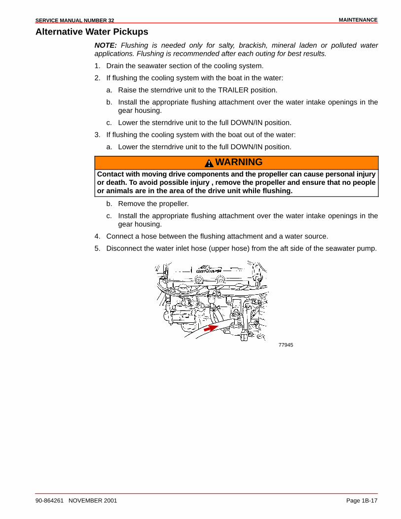
5. Disconnect the water inlet hose (upper hose) from the aft side of the seawater pump.
77945
MAINTENANCE SERVICE MANUAL NUMBER 32
Page 1B-18 90-864261 NOVEMBER 2001
6. Using a suitable adapter, connect the flushing hose from the water source to the waterinlet of the seawater pump.
CAUTIONOverheating from insufficient cooling water will cause engine and drive systemdamage. Ensure that there is sufficient water always available at water inlet holesduring operation.
7. With sterndrive unit in normal operating position, partially open the two water sources(about 1/2 maximum).
8. Place sterndrive in NEUTRAL, idle speed position and start engine.
CAUTIONSuction created by the seawater pickup pump may collapse the flushing water hosecausing the engine to overheat. Avoid engine damage from overheating; do NOToperate the engine above 1500 rpm.
9. Slowly advance throttle until engine reaches 1300 rpm (+/–100 rpm).
CAUTIONEngine overheating can cause engine damage. To avoid, observe the watertemperature gauge and ensure that the engine is operating in the normal range.
10. Observe the water temperature gauge to ensure that the engine is operating in thenormal range.
11. Operate the engine with the sterndrive in NEUTRAL for about 10 minutes or until thedischarge water is clear.
12. Slowly return the throttle to the idle speed position.
13. Stop the engine.
14. Shut off the water and remove the flushing attachments.
15. Install the water inlet hose to the aft side of the seawater pump.
16. Tighten the hose clamp securely.
MAINTENANCESERVICE MANUAL NUMBER 32
90-864261 NOVEMBER 2001 Page 1B-19
Sterndrive Unit Oil
CheckingNOTE: Oil level will fluctuate during operation. The oil level should be checked with a coldengine before starting.
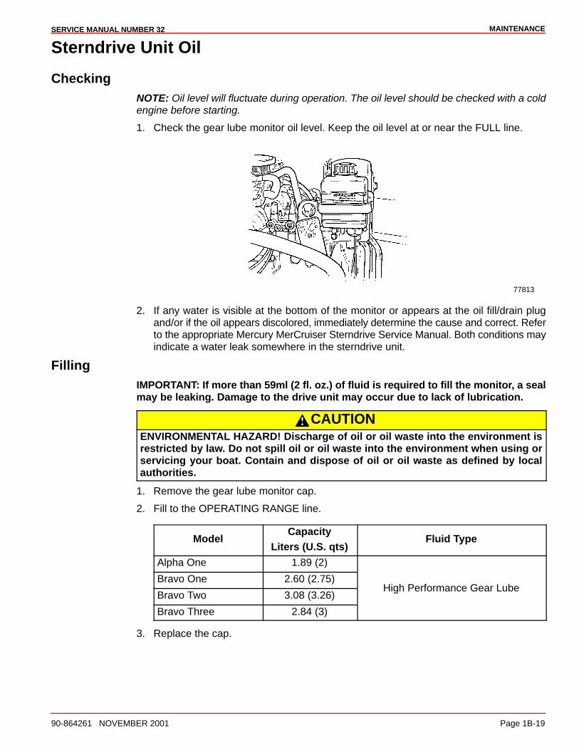
1. Check the gear lube monitor oil level. Keep the oil level at or near the FULL line.
77813
2. If any water is visible at the bottom of the monitor or appears at the oil fill/drain plugand/or if the oil appears discolored, immediately determine the cause and correct. Referto the appropriate Mercury MerCruiser Sterndrive Service Manual. Both conditions mayindicate a water leak somewhere in the sterndrive unit.
FillingIMPORTANT: If more than 59ml (2 fl. oz.) of fluid is required to fill the monitor, a sealmay be leaking. Damage to the drive unit may occur due to lack of lubrication.
CAUTIONENVIRONMENTAL HAZARD! Discharge of oil or oil waste into the environment isrestricted by law. Do not spill oil or oil waste into the environment when using orservicing your boat. Contain and dispose of oil or oil waste as defined by localauthorities.
1. Remove the gear lube monitor cap.
2. Fill to the OPERATING RANGE line.
ModelCapacity
Liters (U.S. qts)Fluid Type
Alpha One 1.89 (2)
Bravo One 2.60 (2.75)
Bravo Two 3.08 (3.26)High Performance Gear Lube
Bravo Three 2.84 (3)
3. Replace the cap.
MAINTENANCE SERVICE MANUAL NUMBER 32
Page 1B-20 90-864261 NOVEMBER 2001
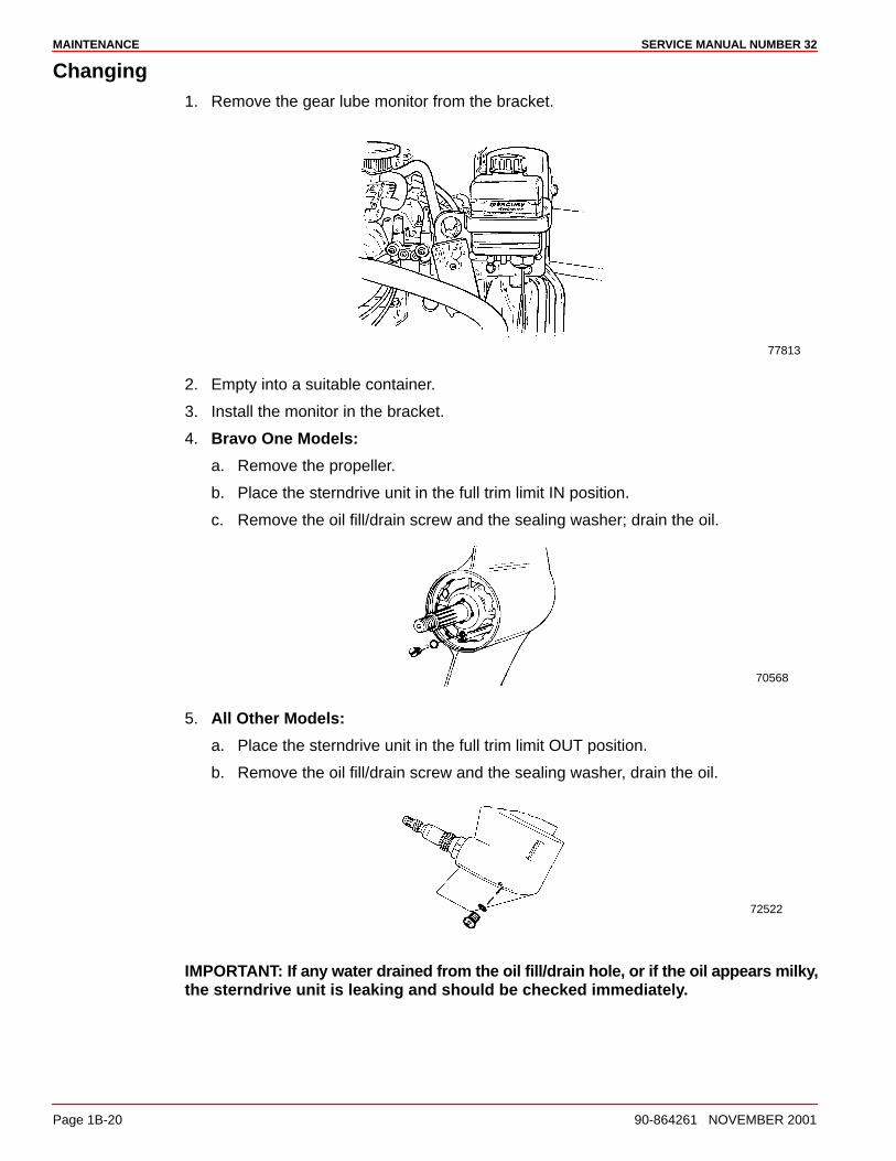
Changing1. Remove the gear lube monitor from the bracket.
77813
2. Empty into a suitable container.
3. Install the monitor in the bracket.
4. Bravo One Models:
a. Remove the propeller.
b. Place the sterndrive unit in the full trim limit IN position.
c. Remove the oil fill/drain screw and the sealing washer; drain the oil.
70568
5. All Other Models:
a. Place the sterndrive unit in the full trim limit OUT position.
b. Remove the oil fill/drain screw and the sealing washer, drain the oil.
72522
IMPORTANT: If any water drained from the oil fill/drain hole, or if the oil appears milky,the sterndrive unit is leaking and should be checked immediately.
MAINTENANCESERVICE MANUAL NUMBER 32
90-864261 NOVEMBER 2001 Page 1B-21
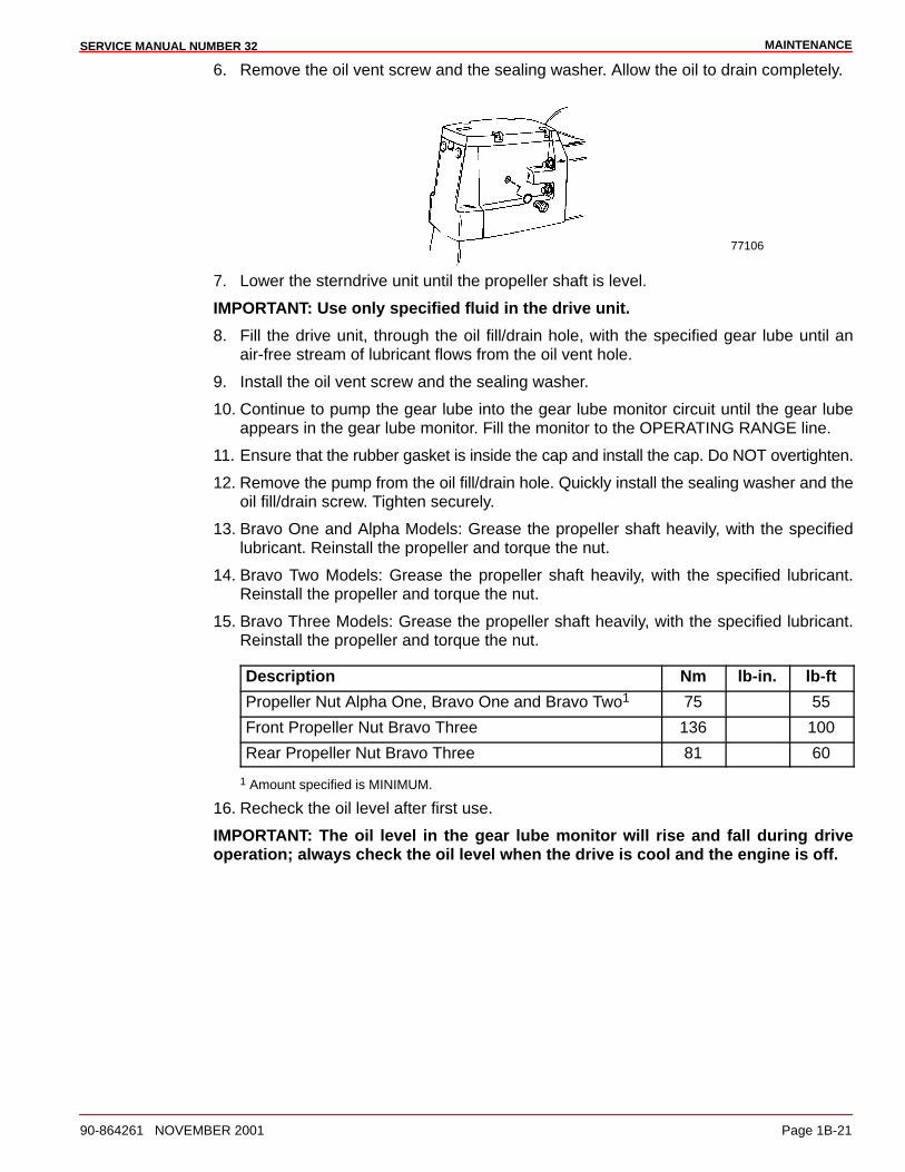
6. Remove the oil vent screw and the sealing washer. Allow the oil to drain completely.
77106
7. Lower the sterndrive unit until the propeller shaft is level.
IMPORTANT: Use only specified fluid in the drive unit.
8. Fill the drive unit, through the oil fill/drain hole, with the specified gear lube until anair-free stream of lubricant flows from the oil vent hole.
9. Install the oil vent screw and the sealing washer.
10. Continue to pump the gear lube into the gear lube monitor circuit until the gear lubeappears in the gear lube monitor. Fill the monitor to the OPERATING RANGE line.
11. Ensure that the rubber gasket is inside the cap and install the cap. Do NOT overtighten.
12. Remove the pump from the oil fill/drain hole. Quickly install the sealing washer and theoil fill/drain screw. Tighten securely.
13. Bravo One and Alpha Models: Grease the propeller shaft heavily, with the specifiedlubricant. Reinstall the propeller and torque the nut.
14. Bravo Two Models: Grease the propeller shaft heavily, with the specified lubricant.Reinstall the propeller and torque the nut.
15. Bravo Three Models: Grease the propeller shaft heavily, with the specified lubricant.Reinstall the propeller and torque the nut.
Description Nm lb-in. lb-ft
Propeller Nut Alpha One, Bravo One and Bravo Two1 75 55
Front Propeller Nut Bravo Three 136 100
Rear Propeller Nut Bravo Three 81 60
1 Amount specified is MINIMUM.
16. Recheck the oil level after first use.
IMPORTANT: The oil level in the gear lube monitor will rise and fall during driveoperation; always check the oil level when the drive is cool and the engine is off.
MAINTENANCE SERVICE MANUAL NUMBER 32
Page 1B-22 90-864261 NOVEMBER 2001
Power Trim Pump Fluid
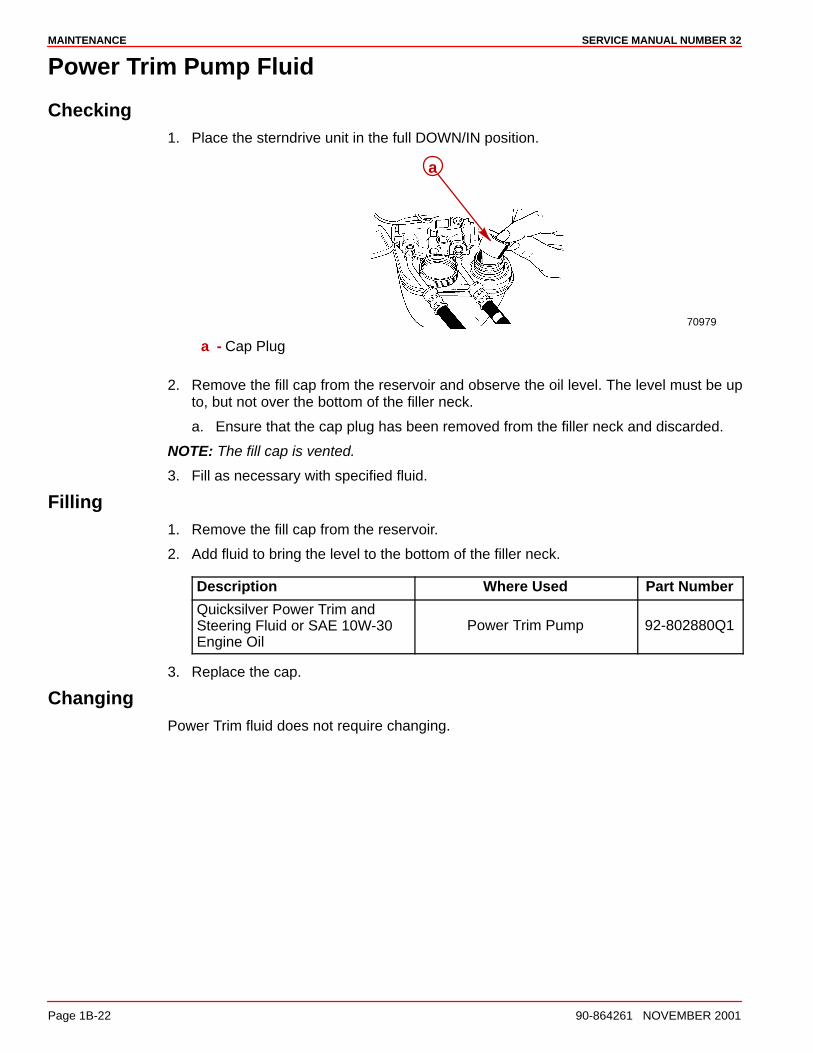
Checking1. Place the sterndrive unit in the full DOWN/IN position.
70979
a
a - Cap Plug
2. Remove the fill cap from the reservoir and observe the oil level. The level must be upto, but not over the bottom of the filler neck.
a. Ensure that the cap plug has been removed from the filler neck and discarded.
NOTE: The fill cap is vented.
3. Fill as necessary with specified fluid.
Filling1. Remove the fill cap from the reservoir.
2. Add fluid to bring the level to the bottom of the filler neck.
Description Where Used Part Number
Quicksilver Power Trim andSteering Fluid or SAE 10W-30Engine Oil
Power Trim Pump 92-802880Q1
3. Replace the cap.
ChangingPower Trim fluid does not require changing.
MAINTENANCESERVICE MANUAL NUMBER 32
90-864261 NOVEMBER 2001 Page 1B-23
Power Steering Pump Fluid
CheckingENGINE WARM
1. Stop the engine. Center the sterndrive unit.
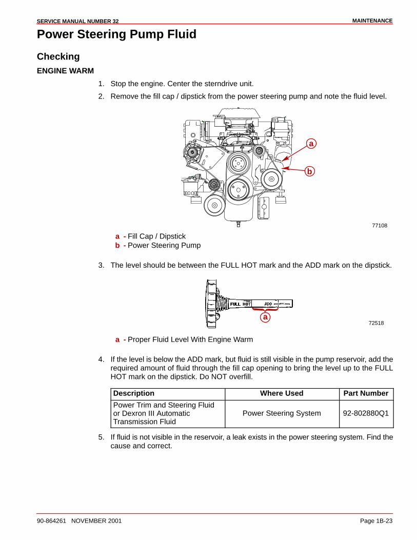
2. Remove the fill cap / dipstick from the power steering pump and note the fluid level.
77108
a
b
a - Fill Cap / Dipstickb - Power Steering Pump
3. The level should be between the FULL HOT mark and the ADD mark on the dipstick.
72518a
a - Proper Fluid Level With Engine Warm
4. If the level is below the ADD mark, but fluid is still visible in the pump reservoir, add therequired amount of fluid through the fill cap opening to bring the level up to the FULLHOT mark on the dipstick. Do NOT overfill.
Description Where Used Part Number
Power Trim and Steering Fluidor Dexron III AutomaticTransmission Fluid
Power Steering System 92-802880Q1
5. If fluid is not visible in the reservoir, a leak exists in the power steering system. Find thecause and correct.
MAINTENANCE SERVICE MANUAL NUMBER 32
Page 1B-24 90-864261 NOVEMBER 2001
ENGINE COLD
1. With the engine stopped, center the sterndrive unit.
2. Remove the fill cap / dipstick from the power steering pump and note the fluid level.
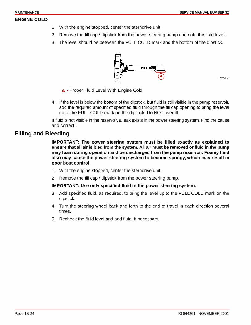
3. The level should be between the FULL COLD mark and the bottom of the dipstick.
72519a
a - Proper Fluid Level With Engine Cold
4. If the level is below the bottom of the dipstick, but fluid is still visible in the pump reservoir,add the required amount of specified fluid through the fill cap opening to bring the levelup to the FULL COLD mark on the dipstick. Do NOT overfill.
If fluid is not visible in the reservoir, a leak exists in the power steering system. Find the causeand correct.
Filling and BleedingIMPORTANT: The power steering system must be filled exactly as explained toensure that all air is bled from the system. All air must be removed or fluid in the pumpmay foam during operation and be discharged from the pump reservoir. Foamy fluidalso may cause the power steering system to become spongy, which may result inpoor boat control.
1. With the engine stopped, center the sterndrive unit.
2. Remove the fill cap / dipstick from the power steering pump.
IMPORTANT: Use only specified fluid in the power steering system.
3. Add specified fluid, as required, to bring the level up to the FULL COLD mark on thedipstick.
4. Turn the steering wheel back and forth to the end of travel in each direction severaltimes.
5. Recheck the fluid level and add fluid, if necessary.
MAINTENANCESERVICE MANUAL NUMBER 32
90-864261 NOVEMBER 2001 Page 1B-25
6. Install the vented fill cap. Tighten securely.
CAUTIONDO NOT operate engine without water being supplied to seawater pickup pump orpump impeller may be damaged and subsequent overheating damage to enginemay result.
7. Start the engine and operate at fast idle (1300 rpm) until the engine reaches normaloperating temperature. During this time, turn the steering wheel back and forth to theend of travel in each direction several times.
8. Center the sterndrive unit and stop the engine.
9. Remove the fill cap from the pump.
10. Allow any foam in the pump reservoir to disperse.
11. Check the fluid level and add fluid, as required, to bring the level up to the FULL HOTmark on the dipstick. Do NOT overfill.
12. Reinstall the fill cap. Tighten securely.
IMPORTANT: The drive unit must be positioned straight back and the power steeringfluid must be hot to accurately check the fluid level.
13. If the fluid is still foamy (in Step 10.), repeat Steps 7. through 12. until the fluid does notfoam and the level remains constant.
MAINTENANCE SERVICE MANUAL NUMBER 32
Page 1B-26 90-864261 NOVEMBER 2001
Water Inlets
All water inlets should be inspected for obstruction. Refer to the maintenance charts for theinterval.
1. Remove debris or marine growth from all water inlets.
2. Flush with clean water.
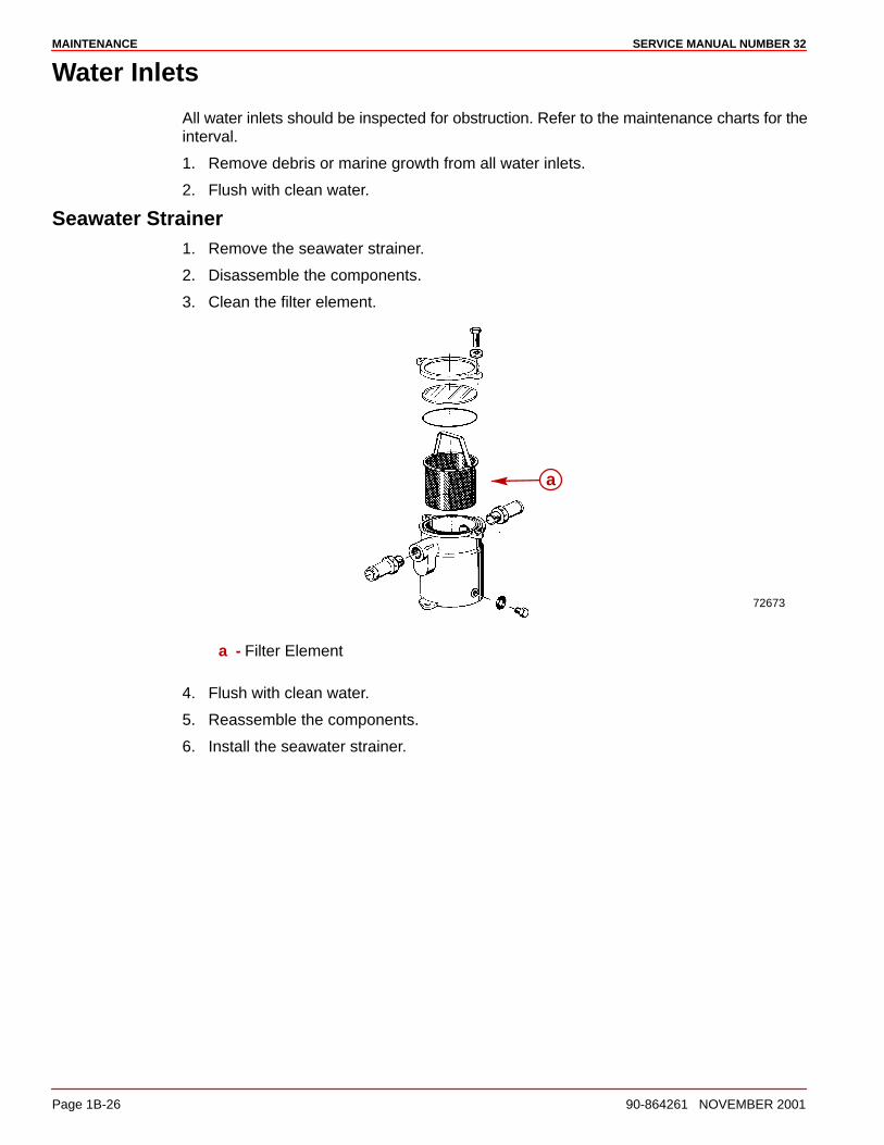
Seawater Strainer1. Remove the seawater strainer.
2. Disassemble the components.
3. Clean the filter element.
72673
a
a - Filter Element
4. Flush with clean water.
5. Reassemble the components.
6. Install the seawater strainer.
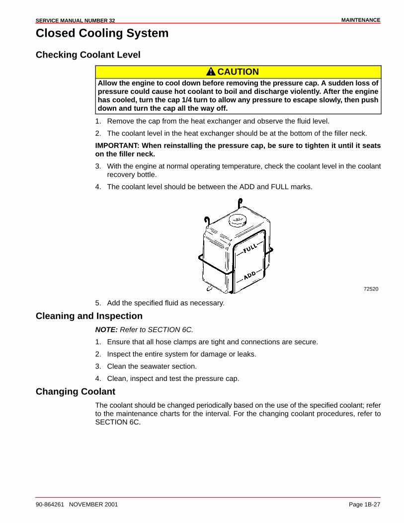
MAINTENANCESERVICE MANUAL NUMBER 32
90-864261 NOVEMBER 2001 Page 1B-27
Closed Cooling System
Checking Coolant Level
CAUTIONAllow the engine to cool down before removing the pressure cap. A sudden loss ofpressure could cause hot coolant to boil and discharge violently. After the enginehas cooled, turn the cap 1/4 turn to allow any pressure to escape slowly, then pushdown and turn the cap all the way off.
1. Remove the cap from the heat exchanger and observe the fluid level.
2. The coolant level in the heat exchanger should be at the bottom of the filler neck.
IMPORTANT: When reinstalling the pressure cap, be sure to tighten it until it seatson the filler neck.
3. With the engine at normal operating temperature, check the coolant level in the coolantrecovery bottle.
4. The coolant level should be between the ADD and FULL marks.
72520
5. Add the specified fluid as necessary.
Cleaning and InspectionNOTE: Refer to SECTION 6C.
1. Ensure that all hose clamps are tight and connections are secure.
2. Inspect the entire system for damage or leaks.
3. Clean the seawater section.
4. Clean, inspect and test the pressure cap.
Changing CoolantThe coolant should be changed periodically based on the use of the specified coolant; referto the maintenance charts for the interval. For the changing coolant procedures, refer toSECTION 6C.
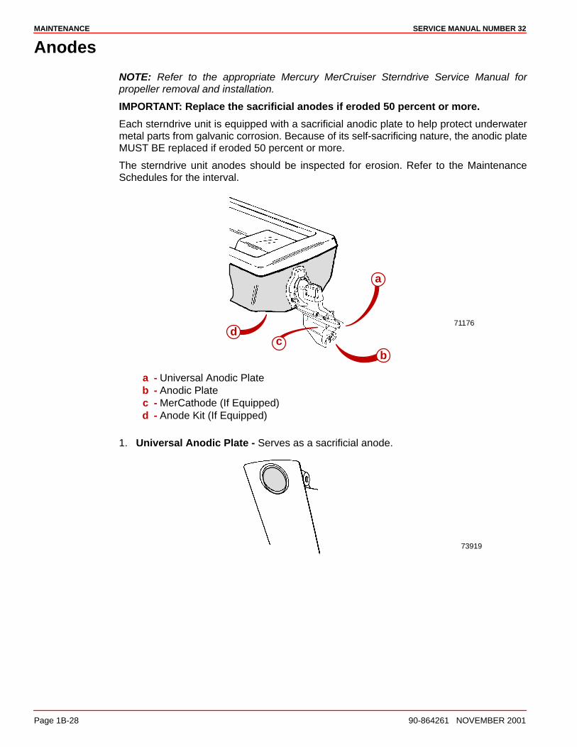
MAINTENANCE SERVICE MANUAL NUMBER 32
Page 1B-28 90-864261 NOVEMBER 2001
Anodes
NOTE: Refer to the appropriate Mercury MerCruiser Sterndrive Service Manual forpropeller removal and installation.
IMPORTANT: Replace the sacrificial anodes if eroded 50 percent or more.
Each sterndrive unit is equipped with a sacrificial anodic plate to help protect underwatermetal parts from galvanic corrosion. Because of its self-sacrificing nature, the anodic plateMUST BE replaced if eroded 50 percent or more.
The sterndrive unit anodes should be inspected for erosion. Refer to the MaintenanceSchedules for the interval.
71176
a
bc
d
a - Universal Anodic Plateb - Anodic Platec - MerCathode (If Equipped)d - Anode Kit (If Equipped)
1. Universal Anodic Plate - Serves as a sacrificial anode.
73919
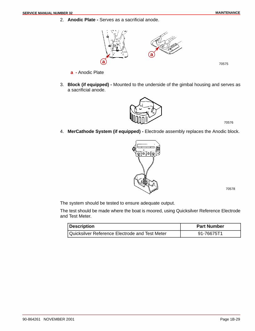
MAINTENANCESERVICE MANUAL NUMBER 32
90-864261 NOVEMBER 2001 Page 1B-29
2. Anodic Plate - Serves as a sacrificial anode.
70575
aa
a - Anodic Plate
3. Block (if equipped) - Mounted to the underside of the gimbal housing and serves asa sacrificial anode.
70576
4. MerCathode System (if equipped) - Electrode assembly replaces the Anodic block.
70578
The system should be tested to ensure adequate output.
The test should be made where the boat is moored, using Quicksilver Reference Electrodeand Test Meter.
Description Part Number
Quicksilver Reference Electrode and Test Meter 91-76675T1
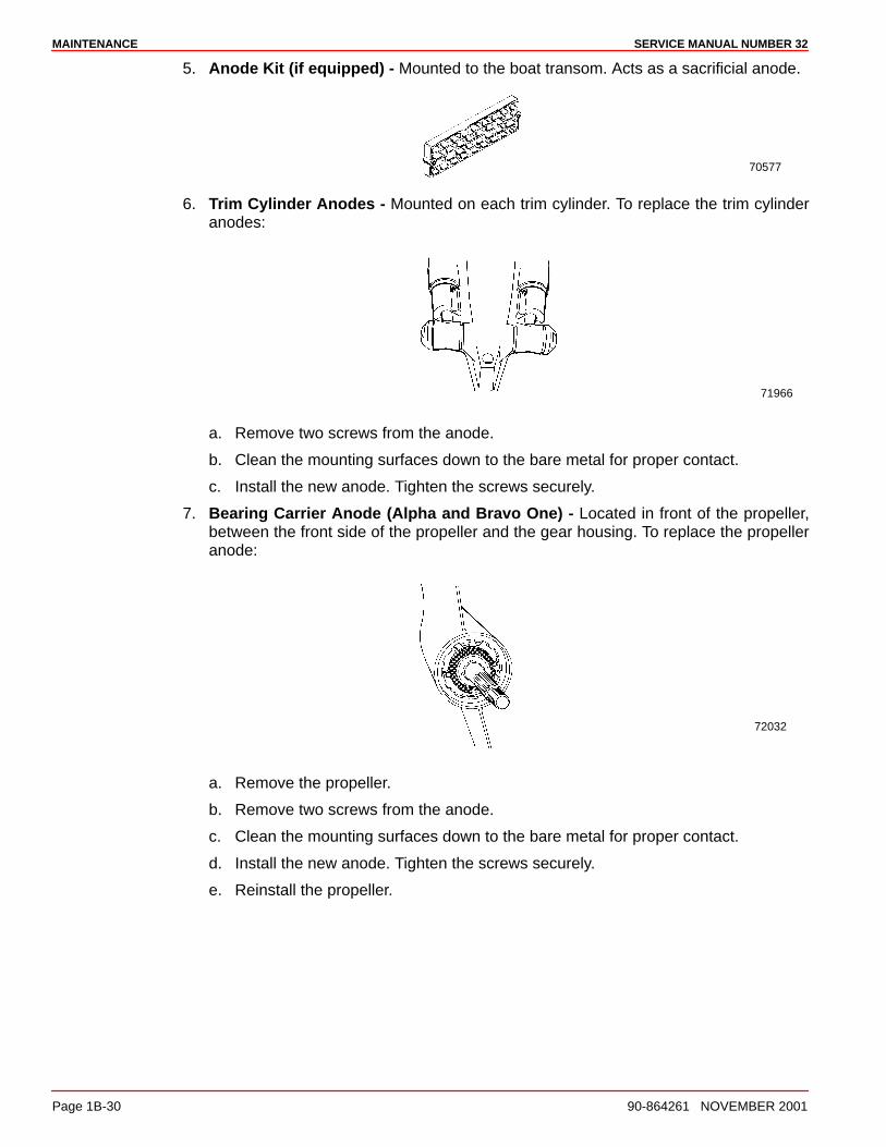
MAINTENANCE SERVICE MANUAL NUMBER 32
Page 1B-30 90-864261 NOVEMBER 2001
5. Anode Kit (if equipped) - Mounted to the boat transom. Acts as a sacrificial anode.
70577
6. Trim Cylinder Anodes - Mounted on each trim cylinder. To replace the trim cylinderanodes:
71966
a. Remove two screws from the anode.
b. Clean the mounting surfaces down to the bare metal for proper contact.
c. Install the new anode. Tighten the screws securely.
7. Bearing Carrier Anode (Alpha and Bravo One) - Located in front of the propeller,between the front side of the propeller and the gear housing. To replace the propelleranode:
72032
a. Remove the propeller.
b. Remove two screws from the anode.
c. Clean the mounting surfaces down to the bare metal for proper contact.
d. Install the new anode. Tighten the screws securely.
e. Reinstall the propeller.
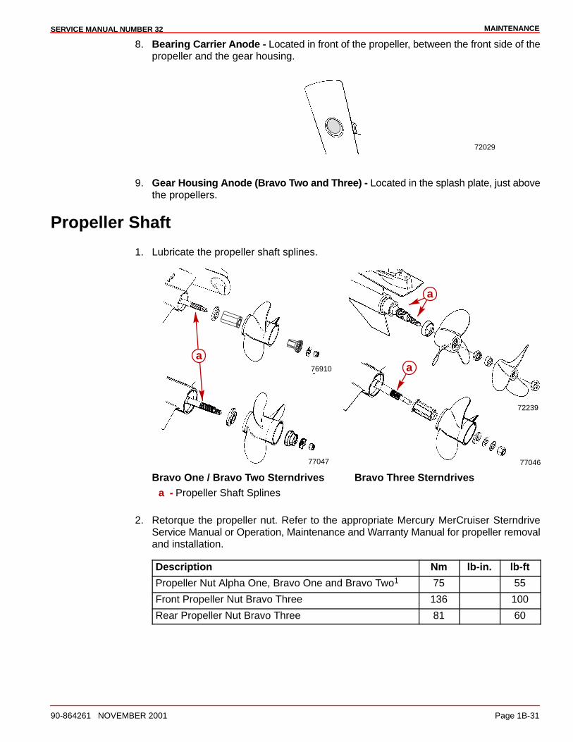
MAINTENANCESERVICE MANUAL NUMBER 32
90-864261 NOVEMBER 2001 Page 1B-31
8. Bearing Carrier Anode - Located in front of the propeller, between the front side of thepropeller and the gear housing.
72029
9. Gear Housing Anode (Bravo Two and Three) - Located in the splash plate, just abovethe propellers.
Propeller Shaft
1. Lubricate the propeller shaft splines.
77047
72239
a
a
a
77046
76910
Bravo One / Bravo Two Sterndrives Bravo Three Sterndrivesa - Propeller Shaft Splines
2. Retorque the propeller nut. Refer to the appropriate Mercury MerCruiser SterndriveService Manual or Operation, Maintenance and Warranty Manual for propeller removaland installation.
Description Nm lb-in. lb-ft
Propeller Nut Alpha One, Bravo One and Bravo Two1 75 55
Front Propeller Nut Bravo Three 136 100
Rear Propeller Nut Bravo Three 81 60

MAINTENANCE SERVICE MANUAL NUMBER 32
Page 1B-32 90-864261 NOVEMBER 2001
Power Package Surfaces
The entire power package should be sprayed at recommended intervals with CorrosionGuard. Follow the instructions on the can for proper application.
NOTE: If operating in saltwater, the interval for treating the engine surface with CorrosionGuard will be reduced. Refer to Maintenance Schedules.
Description Where Used Part Number
Corrosion Guard Spray Power package 92-802878 55
The entire power package should be cleaned and the external surfaces that have becomebare should be repainted with Primer and Spray Paint at recommended intervals. Refer toMaintenance Schedules.
Painting Your Power PackageIMPORTANT: Corrosion damage that results from the improper application ofanti-fouling paint will not be covered by the limited warranty.
1. Painting the boat hull or the boat transom: Anti-fouling paint may be applied to theboat hull and the boat transom but you must observe the following precautions:
IMPORTANT: Do NOT paint the anodes or the MerCathode System referenceelectrode and anode, as this will render them ineffective as galvanic corrosioninhibitors.
IMPORTANT: If anti-fouling protection is required for the boat hull or the boattransom, copper or tin base paints, if not prohibited by law, can be used. If usingcopper or tin based anti-fouling paints, observe the following:
• Avoid any electrical interconnection between the Mercury MerCruiser Product,Anodic Blocks or MerCathode System and the paint by allowing a minimum of40 mm (1-1/2 in.) UNPAINTED area on the transom of the boat around theseitems.
71176a
a - Minimum Unpainted Area
2. Painting Drive Unit or Transom Assembly: The drive unit and the transom assemblyshould be painted with a good quality marine paint or an anti-fouling paint that DOESNOT contain copper, tin or any other material that could conduct an electrical current.Do not paint the drain holes, the anodes, the MerCathode system, and items specifiedby the boat manufacturer.
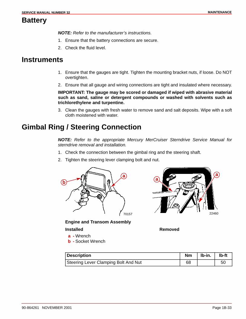
MAINTENANCESERVICE MANUAL NUMBER 32
90-864261 NOVEMBER 2001 Page 1B-33
Battery
NOTE: Refer to the manufacturer’s instructions.
1. Ensure that the battery connections are secure.
2. Check the fluid level.
Instruments
1. Ensure that the gauges are tight. Tighten the mounting bracket nuts, if loose. Do NOTovertighten.
2. Ensure that all gauge and wiring connections are tight and insulated where necessary.
IMPORTANT: The gauge may be scored or damaged if wiped with abrasive materialsuch as sand, saline or detergent compounds or washed with solvents such astrichlorethylene and turpentine.
3. Clean the gauges with fresh water to remove sand and salt deposits. Wipe with a softcloth moistened with water.
Gimbal Ring / Steering Connection
NOTE: Refer to the appropriate Mercury MerCruiser Sterndrive Service Manual forsterndrive removal and installation.
1. Check the connection between the gimbal ring and the steering shaft.
2. Tighten the steering lever clamping bolt and nut.
70157
ÂÂÂÂ
ba
22460
aa
Engine and Transom Assembly
Installed Removeda - Wrenchb - Socket Wrench
Description Nm lb-in. lb-ft
Steering Lever Clamping Bolt And Nut 68 50
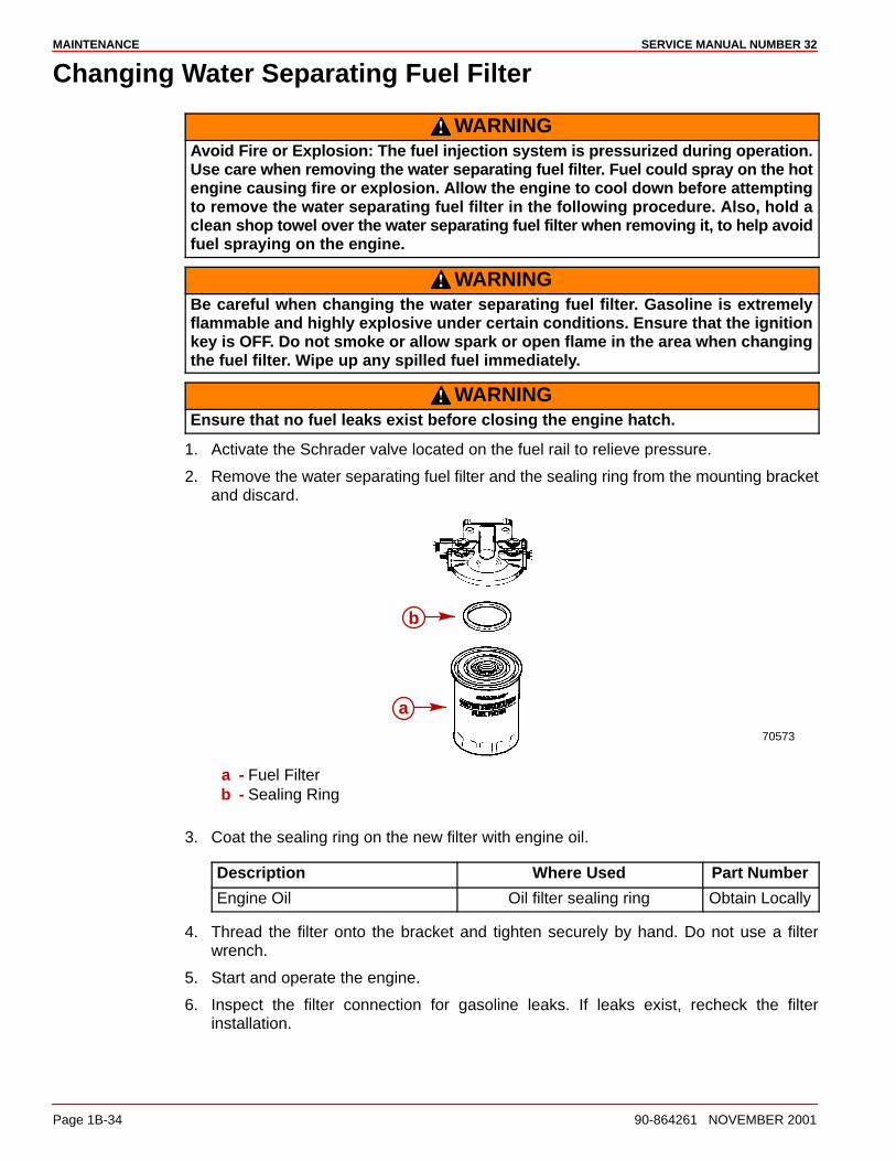
MAINTENANCE SERVICE MANUAL NUMBER 32
Page 1B-34 90-864261 NOVEMBER 2001
Changing Water Separating Fuel Filter
WARNINGAvoid Fire or Explosion: The fuel injection system is pressurized during operation.Use care when removing the water separating fuel filter. Fuel could spray on the hotengine causing fire or explosion. Allow the engine to cool down before attemptingto remove the water separating fuel filter in the following procedure. Also, hold aclean shop towel over the water separating fuel filter when removing it, to help avoidfuel spraying on the engine.
WARNINGBe careful when changing the water separating fuel filter. Gasoline is extremelyflammable and highly explosive under certain conditions. Ensure that the ignitionkey is OFF. Do not smoke or allow spark or open flame in the area when changingthe fuel filter. Wipe up any spilled fuel immediately.
WARNINGEnsure that no fuel leaks exist before closing the engine hatch.
1. Activate the Schrader valve located on the fuel rail to relieve pressure.
2. Remove the water separating fuel filter and the sealing ring from the mounting bracketand discard.
b
a
70573
a - Fuel Filterb - Sealing Ring
3. Coat the sealing ring on the new filter with engine oil.
Description Where Used Part Number
Engine Oil Oil filter sealing ring Obtain Locally
4. Thread the filter onto the bracket and tighten securely by hand. Do not use a filterwrench.
5. Start and operate the engine.
6. Inspect the filter connection for gasoline leaks. If leaks exist, recheck the filterinstallation.

MAINTENANCESERVICE MANUAL NUMBER 32
90-864261 NOVEMBER 2001 Page 1B-35
Steering System
1. Inspect the steering system.
2. Ensure that there are no loose, missing or damaged components.
3. Repair or replace, as necessary.
Remote Control
1. Inspect the remote controls.
2. Ensure that there are no loose, missing or damaged components.
3. Repair or replace, as necessary.
Sterndrive Components
1. Inspect the U-joints.
2. Inspect the engine coupler splines.
3. Inspect the shaft splines.
4. Inspect the bellows.
5. Ensure that there are no loose, missing or damaged components.
6. Repair or replace, as necessary.
Lubrication
Throttle Cable1. Lubricate the pivot points and the guide contact surfaces.
a
b
78033
a - Pivot Pointsb - Guide Contact Surfaces
Description Where Used Part Number
Engine Oil Pivot points, guide contactsurfaces
Obtain Locally

MAINTENANCE SERVICE MANUAL NUMBER 32
Page 1B-36 90-864261 NOVEMBER 2001
Shift CableALL MODELS
1. Lubricate the pivot points and the guide contact surfaces.
b
71357a
Typicala - Pivot Pointsb - Guide Contact Surfaces
Description Where Used Part Number
Engine Oil Pivot points, guide contactsurfaces
Obtain Locally
Sterndrive ComponentsGIMBAL BEARING
1. Lubricate the gimbal bearing by applying approximately 8-10 pumps of grease from atypical hand-operated grease gun.
77068
a
a - Grease Fitting
Description Where Used Part Number
U-joint And Gimbal BearingGrease
Gimbal bearings 92-828052A2
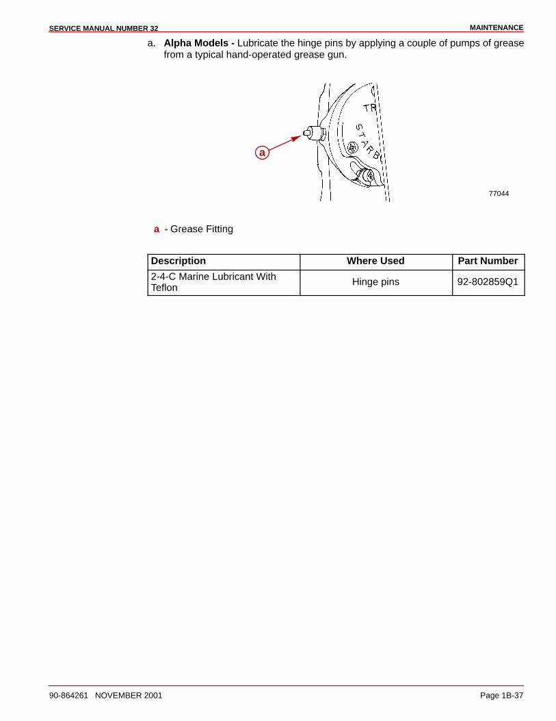
MAINTENANCESERVICE MANUAL NUMBER 32
90-864261 NOVEMBER 2001 Page 1B-37
a. Alpha Models - Lubricate the hinge pins by applying a couple of pumps of greasefrom a typical hand-operated grease gun.
77044
a
a - Grease Fitting
Description Where Used Part Number
2-4-C Marine Lubricant WithTeflon
Hinge pins 92-802859Q1
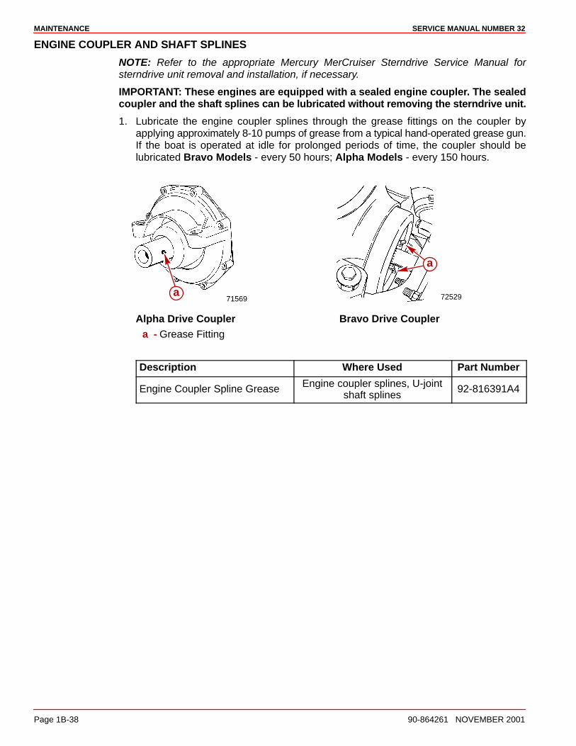
MAINTENANCE SERVICE MANUAL NUMBER 32
Page 1B-38 90-864261 NOVEMBER 2001
ENGINE COUPLER AND SHAFT SPLINES
NOTE: Refer to the appropriate Mercury MerCruiser Sterndrive Service Manual forsterndrive unit removal and installation, if necessary.
IMPORTANT: These engines are equipped with a sealed engine coupler. The sealedcoupler and the shaft splines can be lubricated without removing the sterndrive unit.
1. Lubricate the engine coupler splines through the grease fittings on the coupler byapplying approximately 8-10 pumps of grease from a typical hand-operated grease gun.If the boat is operated at idle for prolonged periods of time, the coupler should belubricated Bravo Models - every 50 hours; Alpha Models - every 150 hours.
71569 72529
a
a
Alpha Drive Coupler Bravo Drive Couplera - Grease Fitting
Description Where Used Part Number
Engine Coupler Spline Grease Engine coupler splines, U-jointshaft splines
92-816391A4
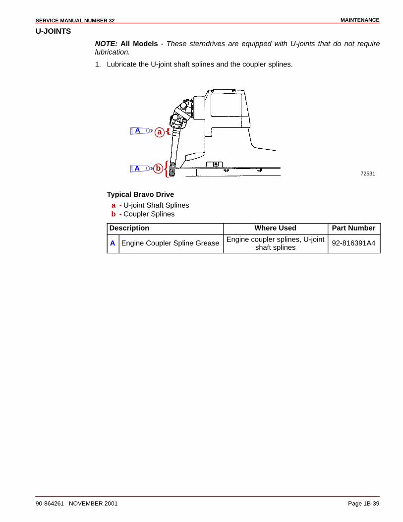
MAINTENANCESERVICE MANUAL NUMBER 32
90-864261 NOVEMBER 2001 Page 1B-39
U-JOINTS
NOTE: All Models - These sterndrives are equipped with U-joints that do not requirelubrication.
1. Lubricate the U-joint shaft splines and the coupler splines.
72531
a
bA
A
Typical Bravo Drivea - U-joint Shaft Splinesb - Coupler Splines
Description Where Used Part Number
A Engine Coupler Spline Grease Engine coupler splines, U-jointshaft splines
92-816391A4
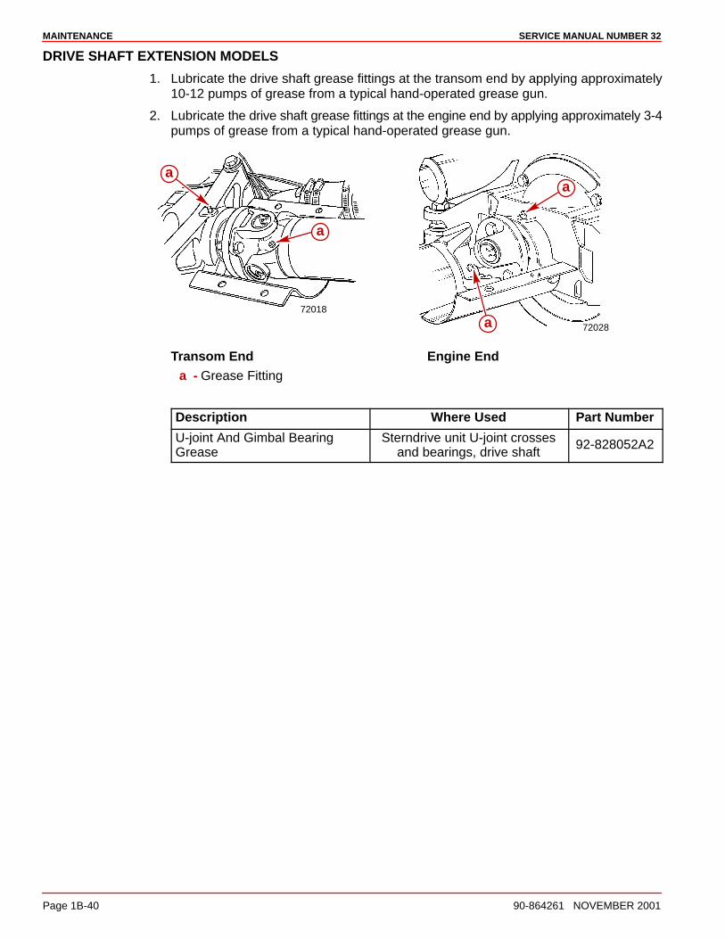
MAINTENANCE SERVICE MANUAL NUMBER 32
Page 1B-40 90-864261 NOVEMBER 2001
DRIVE SHAFT EXTENSION MODELS
1. Lubricate the drive shaft grease fittings at the transom end by applying approximately10-12 pumps of grease from a typical hand-operated grease gun.
2. Lubricate the drive shaft grease fittings at the engine end by applying approximately 3-4pumps of grease from a typical hand-operated grease gun.
72018
a
a
72028
a
a
Transom End Engine Enda - Grease Fitting
Description Where Used Part Number
U-joint And Gimbal BearingGrease
Sterndrive unit U-joint crossesand bearings, drive shaft
92-828052A2
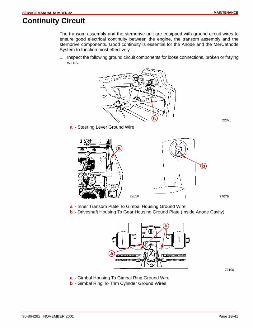
MAINTENANCESERVICE MANUAL NUMBER 32
90-864261 NOVEMBER 2001 Page 1B-41
Continuity Circuit
The transom assembly and the sterndrive unit are equipped with ground circuit wires toensure good electrical continuity between the engine, the transom assembly and thesterndrive components. Good continuity is essential for the Anode and the MerCathodeSystem to function most effectively.
1. Inspect the following ground circuit components for loose connections, broken or frayingwires.
22028a
a - Steering Lever Ground Wire
22650 77079
a
b
a - Inner Transom Plate To Gimbal Housing Ground Wireb - Driveshaft Housing To Gear Housing Ground Plate (Inside Anode Cavity)
77100
a
b
a - Gimbal Housing To Gimbal Ring Ground Wireb - Gimbal Ring To Trim Cylinder Ground Wires
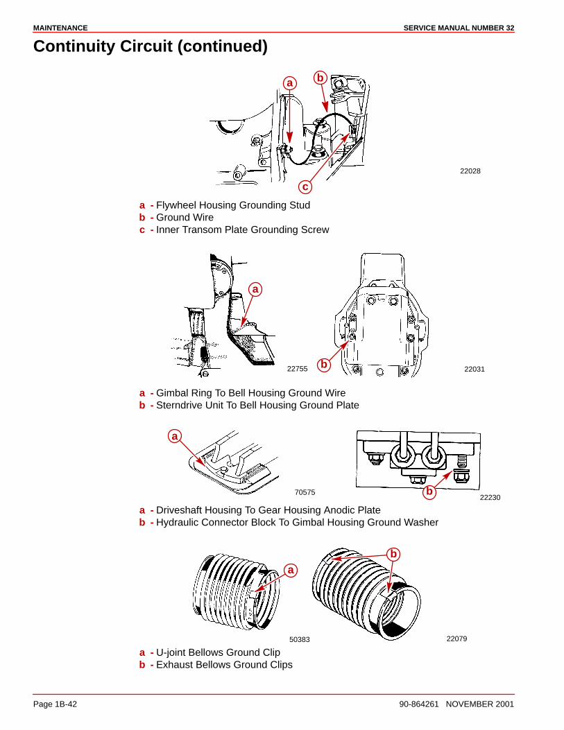
MAINTENANCE SERVICE MANUAL NUMBER 32
Page 1B-42 90-864261 NOVEMBER 2001
Continuity Circuit (continued)
22028
a b
c
a - Flywheel Housing Grounding Studb - Ground Wirec - Inner Transom Plate Grounding Screw
22755 22031
a
b
a - Gimbal Ring To Bell Housing Ground Wireb - Sterndrive Unit To Bell Housing Ground Plate
7057522230
a
b
a - Driveshaft Housing To Gear Housing Anodic Plateb - Hydraulic Connector Block To Gimbal Housing Ground Washer
50383 22079
ba
a - U-joint Bellows Ground Clipb - Exhaust Bellows Ground Clips
MAINTENANCESERVICE MANUAL NUMBER 32
90-864261 NOVEMBER 2001 Page 1B-43
MerCathode
If the boat is equipped with a Quicksilver MerCathode System, the system should be testedto ensure that it is providing adequate output to protect the underwater metal parts on theboat. The test should be made where the boat is moored, using Quicksilver ReferenceElectrode and Test Meter.
Description Part Number
Quicksilver Reference Electrode and Test Meter 91-76675T1
Refer to the appropriate Mercury MerCruiser Sterndrive Service Manual for testingprocedures.
Engine Mounts
1. Torque the rear engine mounts. Refer to SECTION 2.
Description Nm lb-in. lb-ft
Rear Engine Mounts 51 38
Electrical System
NOTE: Refer to SECTION 4 for specific procedures.
1. Inspect the spark plugs.
2. Inspect the spark plug wires.
3. Inspect the distributor cap.
4. Inspect the entire electrical system for loose, damaged or corroded fasteners.
MAINTENANCE SERVICE MANUAL NUMBER 32
Page 1B-44 90-864261 NOVEMBER 2001
Cleaning Flame Arrestor
1. Remove the engine cover.
2. Remove the crankcase ventilation hose from the fitting on the side of the flame arrestorhousing.
3. Remove the flame arrestor.
4. Clean the flame arrestor with water or steam. Dry with compressed air.
5. Clean the crankcase ventilation hoses. Dry with compressed air.
6. Inspect the crankcase ventilation hoses for cracks or deterioration and replace ifnecessary.
7. Install the flame arrestor and the crankcase ventilation hoses.
8. Install the flame arrestor bracket and tighten the nuts.
Description Nm lb-in. lb-ft
Flame Arrestor Bracket Nuts 12 9
9. Install the engine cover.
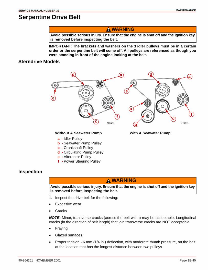
MAINTENANCESERVICE MANUAL NUMBER 32
90-864261 NOVEMBER 2001 Page 1B-45
Serpentine Drive Belt
WARNINGAvoid possible serious injury. Ensure that the engine is shut off and the ignition keyis removed before inspecting the belt.
IMPORTANT: The brackets and washers on the 3 idler pulleys must be in a certainorder or the serpentine belt will come off. All pulleys are referenced as though youwere standing in front of the engine looking at the belt.
Sterndrive Models
a
e
a
bc
c
dd
e
f fa
78022 78021
Without A Seawater Pump With A Seawater Pumpa - Idler Pulleyb - Seawater Pump Pulleyc - Crankshaft Pulleyd - Circulating Pump Pulleye - Alternator Pulleyf - Power Steering Pulley
Inspection
WARNINGAvoid possible serious injury. Ensure that the engine is shut off and the ignition keyis removed before inspecting the belt.
1. Inspect the drive belt for the following:
• Excessive wear
• Cracks
NOTE: Minor, transverse cracks (across the belt width) may be acceptable. Longitudinalcracks (in the direction of belt length) that join transverse cracks are NOT acceptable.
• Fraying
• Glazed surfaces
• Proper tension - 6 mm (1/4 in.) deflection, with moderate thumb pressure, on the beltat the location that has the longest distance between two pulleys.
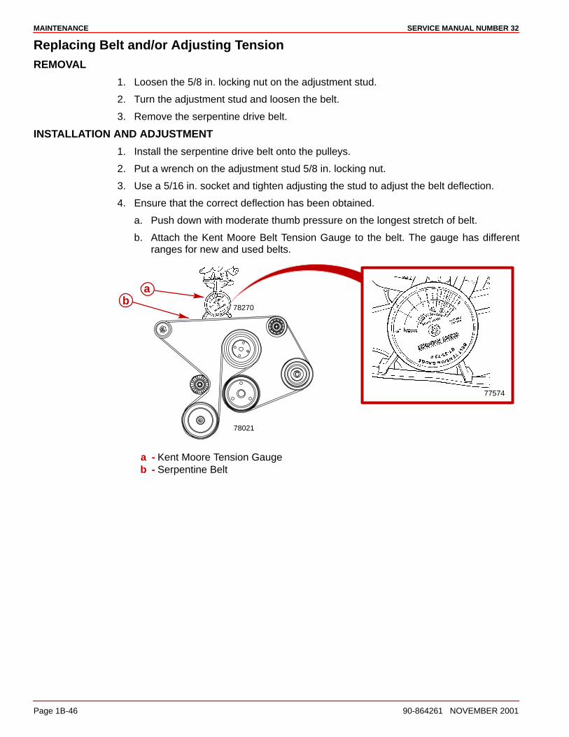
MAINTENANCE SERVICE MANUAL NUMBER 32
Page 1B-46 90-864261 NOVEMBER 2001
Replacing Belt and/or Adjusting TensionREMOVAL
1. Loosen the 5/8 in. locking nut on the adjustment stud.
2. Turn the adjustment stud and loosen the belt.
3. Remove the serpentine drive belt.
INSTALLATION AND ADJUSTMENT
1. Install the serpentine drive belt onto the pulleys.
2. Put a wrench on the adjustment stud 5/8 in. locking nut.
3. Use a 5/16 in. socket and tighten adjusting the stud to adjust the belt deflection.
4. Ensure that the correct deflection has been obtained.
a. Push down with moderate thumb pressure on the longest stretch of belt.
b. Attach the Kent Moore Belt Tension Gauge to the belt. The gauge has differentranges for new and used belts.
ab
78270
77574
78021
a - Kent Moore Tension Gaugeb - Serpentine Belt
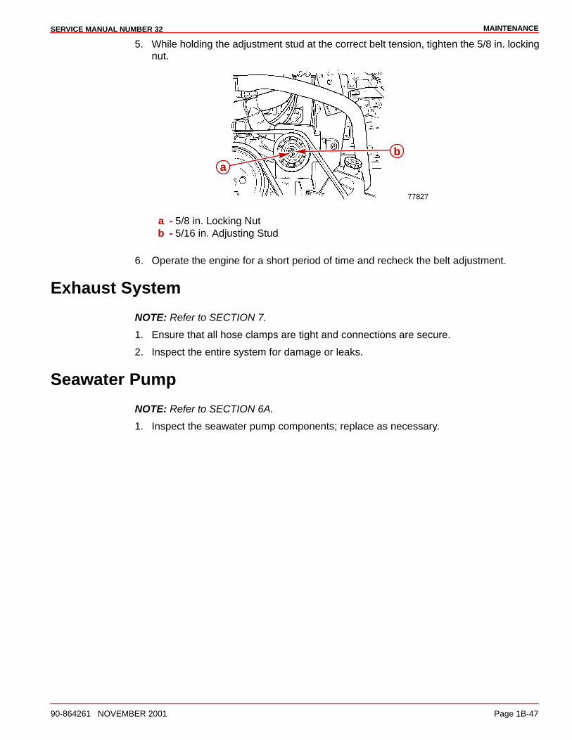
MAINTENANCESERVICE MANUAL NUMBER 32
90-864261 NOVEMBER 2001 Page 1B-47
5. While holding the adjustment stud at the correct belt tension, tighten the 5/8 in. lockingnut.
77827
ab
a - 5/8 in. Locking Nutb - 5/16 in. Adjusting Stud
6. Operate the engine for a short period of time and recheck the belt adjustment.
Exhaust System
NOTE: Refer to SECTION 7.
1. Ensure that all hose clamps are tight and connections are secure.
2. Inspect the entire system for damage or leaks.
Seawater Pump
NOTE: Refer to SECTION 6A.
1. Inspect the seawater pump components; replace as necessary.
MAINTENANCE SERVICE MANUAL NUMBER 32
Page 1B-48 90-864261 NOVEMBER 2001
Cold Weather And Extended Storage
IMPORTANT: Mercury MerCruiser strongly recommends that this service should beperformed by an authorized Mercury MerCruiser dealer. Damage caused by freezingIS NOT covered by the Mercury MerCruiser Limited Warranty.
CAUTIONSterndrive unit should be stored in the full DOWN position. Universal joint bellowsmay develop a “set” if unit is stored in raised position and may fail when unit isreturned to service.
IMPORTANT: Mercury MerCruiser recommends that propylene glycol antifreeze (anontoxic and environmentally safe antifreeze) be used in the seawater section of thecooling system for cold weather or extended storage. Ensure that the propyleneglycol antifreeze contains a rust inhibitor and is recommended for use in marineengines. Be certain to follow the propylene glycol manufacturer’s recommendations.
CAUTIONThe seawater section of the cooling system MUST BE COMPLETELY drained forwinter storage, or immediately after cold weather use, if the possibility of freezingtemperatures exist. Failure to comply may result in trapped water causing freezeand/or corrosion damage to the engine. Damage caused by freezing is NOT coveredby the Mercury MerCruiser Limited Warranty.
Preparing Your Power Package For Storage1. Fill the fuel tanks with fresh gasoline (that does not contain alcohol) and a sufficient
amount of Mercury Fuel System Treatment and Stabilizer to treat the gasoline. Followinstructions on the container.
2. If the boat is to be placed in storage with fuel containing alcohol in fuel tanks (iffuel without alcohol is not available): Fuel tanks should be drained as low as possibleand Quicksilver Gasoline Stabilizer for Marine Engines added to any fuel remaining inthe tank.
NOTE: If desired, a portable fuel tank can be used to perform the remainder of the powerpackage lay up procedures. Be sure to add an appropriate amount of Gasoline Stabilizerto the portable tank.
3. Flush the cooling system.
4. Change the oil and oil filter.
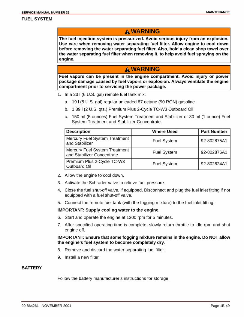
MAINTENANCESERVICE MANUAL NUMBER 32
90-864261 NOVEMBER 2001 Page 1B-49
FUEL SYSTEM
WARNINGThe fuel injection system is pressurized. Avoid serious injury from an explosion.Use care when removing water separating fuel filter. Allow engine to cool downbefore removing the water separating fuel filter. Also, hold a clean shop towel overthe water separating fuel filter when removing it, to help avoid fuel spraying on theengine.
WARNINGFuel vapors can be present in the engine compartment. Avoid injury or powerpackage damage caused by fuel vapors or explosion. Always ventilate the enginecompartment prior to servicing the power package.
1. In a 23 l (6 U.S. gal) remote fuel tank mix:
a. 19 l (5 U.S. gal) regular unleaded 87 octane (90 RON) gasoline
b. 1.89 l (2 U.S. qts.) Premium Plus 2-Cycle TC-W3 Outboard Oil
c. 150 ml (5 ounces) Fuel System Treatment and Stabilizer or 30 ml (1 ounce) FuelSystem Treatment and Stabilizer Concentrate.
Description Where Used Part Number
Mercury Fuel System Treatmentand Stabilizer
Fuel System 92-802875A1
Mercury Fuel System Treatmentand Stabilizer Concentrate
Fuel System 92-802876A1
Premium Plus 2-Cycle TC-W3Outboard Oil
Fuel System 92-802824A1
2. Allow the engine to cool down.
3. Activate the Schrader valve to relieve fuel pressure.
4. Close the fuel shut-off valve, if equipped. Disconnect and plug the fuel inlet fitting if notequipped with a fuel shut-off valve.
5. Connect the remote fuel tank (with the fogging mixture) to the fuel inlet fitting.
IMPORTANT: Supply cooling water to the engine.
6. Start and operate the engine at 1300 rpm for 5 minutes.
7. After specified operating time is complete, slowly return throttle to idle rpm and shutengine off.
IMPORTANT: Ensure that some fogging mixture remains in the engine. Do NOT allowthe engine’s fuel system to become completely dry.
8. Remove and discard the water separating fuel filter.
9. Install a new filter.
BATTERY
Follow the battery manufacturer’s instructions for storage.
MAINTENANCE SERVICE MANUAL NUMBER 32
Page 1B-50 90-864261 NOVEMBER 2001
Draining Instructions
CAUTIONEnsure that boat is out of the water or seacock is closed and bilge pump is operatingbefore beginning procedure. Excess water in bilge can damage engine or causeboat to sink.
CAUTIONDo not operate engine with drain system open. Excess water in bilge can damageengine or cause boat to sink.
IMPORTANT: Boat must be as level as possible to ensure complete draining ofcooling system.
Your power package is equipped with one of three drain systems. Refer to Identification onthe following page to determine which instructions apply to your power package.
The power package should be drained before flushing or prior to extended or cold weatherstorage.
IMPORTANT: The boat must not be operating at any point during this procedure.
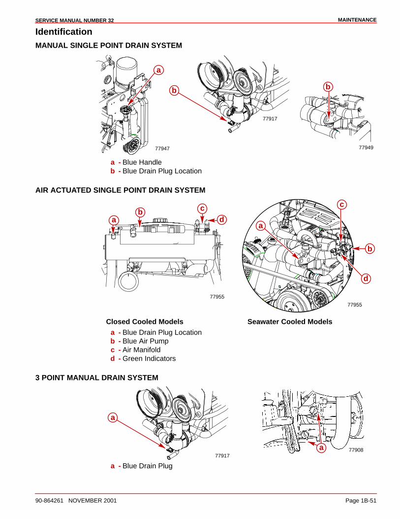
MAINTENANCESERVICE MANUAL NUMBER 32
90-864261 NOVEMBER 2001 Page 1B-51
IdentificationMANUAL SINGLE POINT DRAIN SYSTEM
77947 77949
b
a
77917
b
a - Blue Handleb - Blue Drain Plug Location
AIR ACTUATED SINGLE POINT DRAIN SYSTEM
ba d
c
77955
77955
a
b
c
d
Closed Cooled Models Seawater Cooled Modelsa - Blue Drain Plug Locationb - Blue Air Pumpc - Air Manifoldd - Green Indicators
3 POINT MANUAL DRAIN SYSTEM
7790877917
a
a
a - Blue Drain Plug

MAINTENANCE SERVICE MANUAL NUMBER 32
Page 1B-52 90-864261 NOVEMBER 2001
Boat In The WaterMANUAL SINGLE POINT DRAIN SYSTEM
1. Close the seacock.
2. Rotate the blue handle COUNTERCLOCKWISE until it stops (approximately 2 turns).The red on the handle shaft indicates that the drain system is open. Do not force thehandle as this will create new threads.
3. Immediately remove the blue drain plug from the side of the thermostat housing. Thismust be removed within 30 seconds to properly vent the cooling system.
77947
77949
b
a
a - Blue Handleb - Blue Drain Plug Location
4. Visually verify that water is draining. If water does not drain, remove blue drain plug fromdistribution housing and drain manually.
77917
a
b
a - Drain Location - Orange Or Redb - Blue Drain Plug
5. Allow the system to drain for a minimum of 5 minutes. Mercury MerCruiser recommendsleaving the drain system open while transporting the boat or while performing othermaintenance.
6. Reinstall the blue drain plug in the thermostat housing.
7. Close the drain system by rotating the blue handle CLOCKWISE until it stops and installthe blue drain plug, if removed. The handle is fully seated when no red is visible. Do notovertighten the handle as this will create new threads.
8. Open the seacock prior to operating the engine.
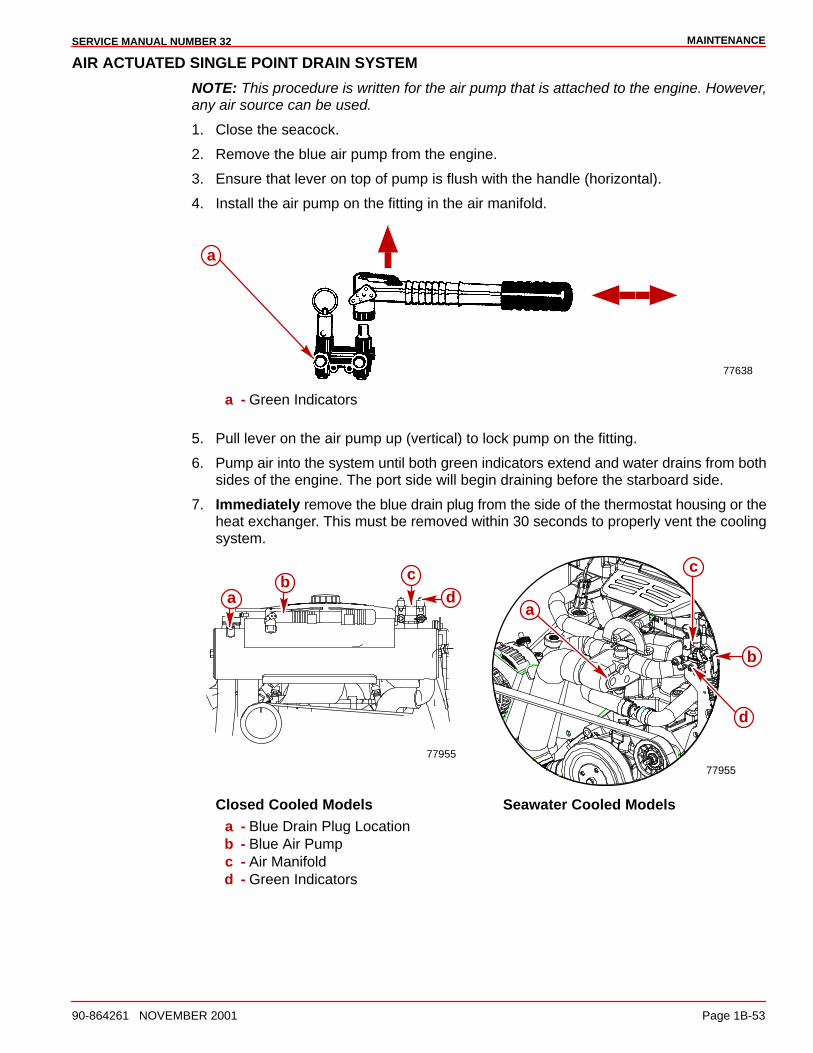
MAINTENANCESERVICE MANUAL NUMBER 32
90-864261 NOVEMBER 2001 Page 1B-53
AIR ACTUATED SINGLE POINT DRAIN SYSTEM
NOTE: This procedure is written for the air pump that is attached to the engine. However,any air source can be used.
1. Close the seacock.
2. Remove the blue air pump from the engine.
3. Ensure that lever on top of pump is flush with the handle (horizontal).
4. Install the air pump on the fitting in the air manifold.
77638
a
a - Green Indicators
5. Pull lever on the air pump up (vertical) to lock pump on the fitting.
6. Pump air into the system until both green indicators extend and water drains from bothsides of the engine. The port side will begin draining before the starboard side.
7. Immediately remove the blue drain plug from the side of the thermostat housing or theheat exchanger. This must be removed within 30 seconds to properly vent the coolingsystem.
ba d
c
77955
77955
a
b
c
d
Closed Cooled Models Seawater Cooled Modelsa - Blue Drain Plug Locationb - Blue Air Pumpc - Air Manifoldd - Green Indicators
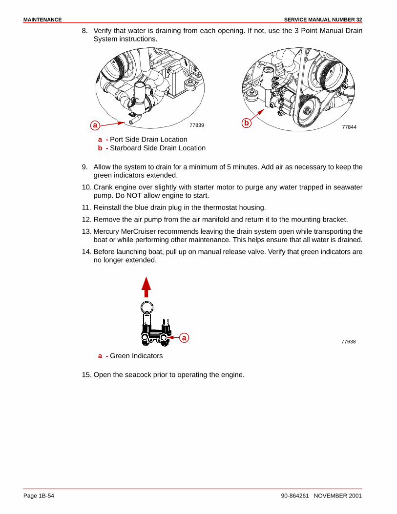
MAINTENANCE SERVICE MANUAL NUMBER 32
Page 1B-54 90-864261 NOVEMBER 2001
8. Verify that water is draining from each opening. If not, use the 3 Point Manual DrainSystem instructions.
7784477839 ba
a - Port Side Drain Locationb - Starboard Side Drain Location
9. Allow the system to drain for a minimum of 5 minutes. Add air as necessary to keep thegreen indicators extended.
10. Crank engine over slightly with starter motor to purge any water trapped in seawaterpump. Do NOT allow engine to start.
11. Reinstall the blue drain plug in the thermostat housing.
12. Remove the air pump from the air manifold and return it to the mounting bracket.
13. Mercury MerCruiser recommends leaving the drain system open while transporting theboat or while performing other maintenance. This helps ensure that all water is drained.
14. Before launching boat, pull up on manual release valve. Verify that green indicators areno longer extended.
77638a
a - Green Indicators
15. Open the seacock prior to operating the engine.
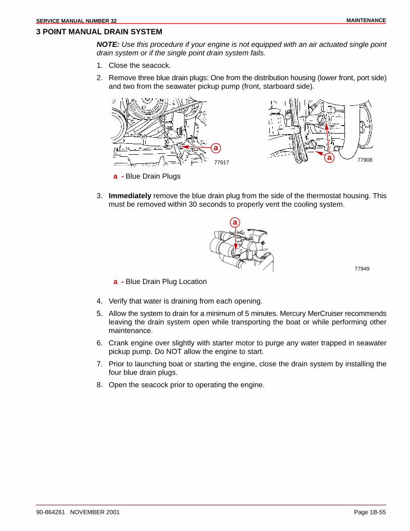
MAINTENANCESERVICE MANUAL NUMBER 32
90-864261 NOVEMBER 2001 Page 1B-55
3 POINT MANUAL DRAIN SYSTEM
NOTE: Use this procedure if your engine is not equipped with an air actuated single pointdrain system or if the single point drain system fails.
1. Close the seacock.
2. Remove three blue drain plugs: One from the distribution housing (lower front, port side)and two from the seawater pickup pump (front, starboard side).
7790877917a
a
a - Blue Drain Plugs
3. Immediately remove the blue drain plug from the side of the thermostat housing. Thismust be removed within 30 seconds to properly vent the cooling system.
77949
a
a - Blue Drain Plug Location
4. Verify that water is draining from each opening.
5. Allow the system to drain for a minimum of 5 minutes. Mercury MerCruiser recommendsleaving the drain system open while transporting the boat or while performing othermaintenance.
6. Crank engine over slightly with starter motor to purge any water trapped in seawaterpickup pump. Do NOT allow the engine to start.
7. Prior to launching boat or starting the engine, close the drain system by installing thefour blue drain plugs.
8. Open the seacock prior to operating the engine.
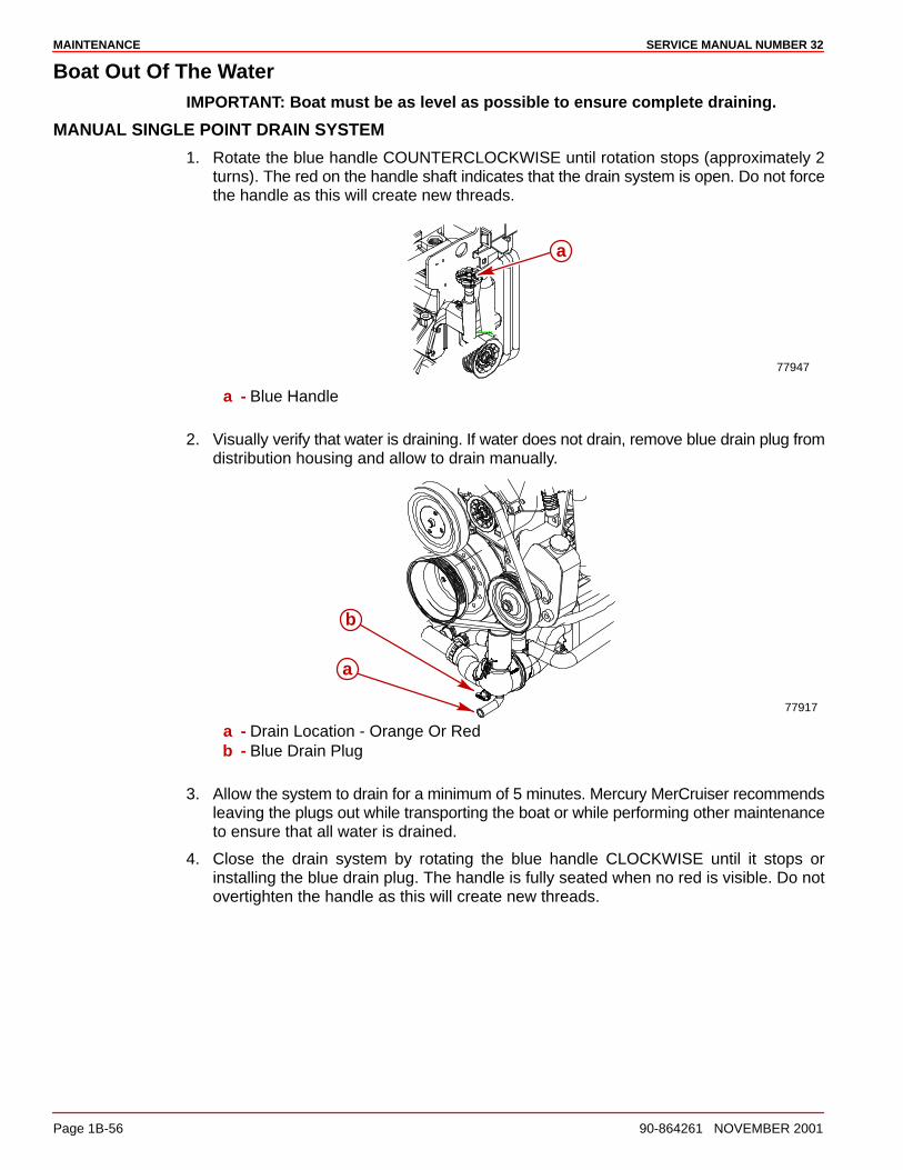
MAINTENANCE SERVICE MANUAL NUMBER 32
Page 1B-56 90-864261 NOVEMBER 2001
Boat Out Of The WaterIMPORTANT: Boat must be as level as possible to ensure complete draining.
MANUAL SINGLE POINT DRAIN SYSTEM
1. Rotate the blue handle COUNTERCLOCKWISE until rotation stops (approximately 2turns). The red on the handle shaft indicates that the drain system is open. Do not forcethe handle as this will create new threads.
77947
a
a - Blue Handle
2. Visually verify that water is draining. If water does not drain, remove blue drain plug fromdistribution housing and allow to drain manually.
77917
a
b
a - Drain Location - Orange Or Redb - Blue Drain Plug
3. Allow the system to drain for a minimum of 5 minutes. Mercury MerCruiser recommendsleaving the plugs out while transporting the boat or while performing other maintenanceto ensure that all water is drained.
4. Close the drain system by rotating the blue handle CLOCKWISE until it stops orinstalling the blue drain plug. The handle is fully seated when no red is visible. Do notovertighten the handle as this will create new threads.

MAINTENANCESERVICE MANUAL NUMBER 32
90-864261 NOVEMBER 2001 Page 1B-57
AIR ACTUATED SINGLE POINT DRAIN SYSTEM
NOTE: This procedure is written for the air pump that is attached to the engine. However,any air source can be used.
1. Remove the blue air pump from the engine.
2. Ensure that lever on top of pump is flush with the handle (horizontal).
3. Install the air pump on the fitting in the air manifold.
77638
a
a - Green Indicators
4. Pull the lever on the air pump up (vertical) to lock the pump on the fitting.
5. Pump air into the system until both green indicators extend and water drains from bothsides of the engine. The port side will begin draining before the starboard side.
ba d
c
77955
77955
a
b
c
d
Closed Cooled Models Seawater Cooled Modelsa - Blue Drain Plug Locationb - Blue Air Pumpc - Air Manifoldd - Green Indicators
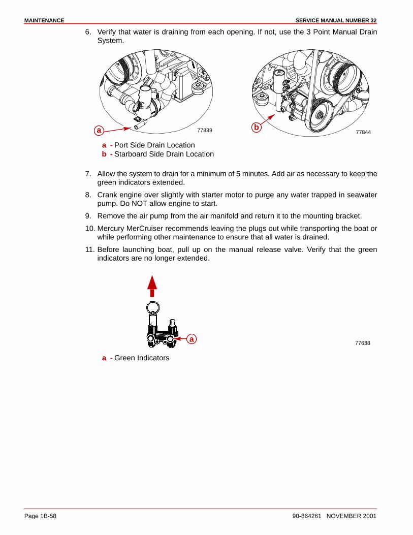
MAINTENANCE SERVICE MANUAL NUMBER 32
Page 1B-58 90-864261 NOVEMBER 2001
6. Verify that water is draining from each opening. If not, use the 3 Point Manual DrainSystem.
7784477839 ba
a - Port Side Drain Locationb - Starboard Side Drain Location
7. Allow the system to drain for a minimum of 5 minutes. Add air as necessary to keep thegreen indicators extended.
8. Crank engine over slightly with starter motor to purge any water trapped in seawaterpump. Do NOT allow engine to start.
9. Remove the air pump from the air manifold and return it to the mounting bracket.
10. Mercury MerCruiser recommends leaving the plugs out while transporting the boat orwhile performing other maintenance to ensure that all water is drained.
11. Before launching boat, pull up on the manual release valve. Verify that the greenindicators are no longer extended.
77638a
a - Green Indicators
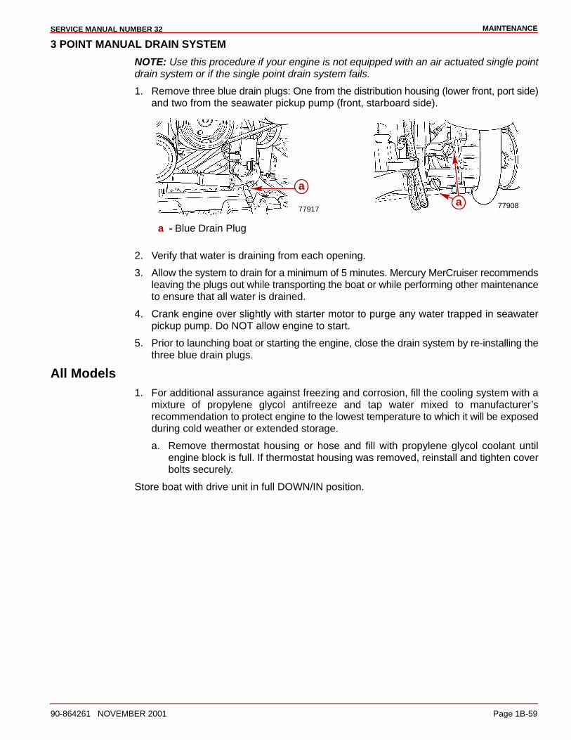
MAINTENANCESERVICE MANUAL NUMBER 32
90-864261 NOVEMBER 2001 Page 1B-59
3 POINT MANUAL DRAIN SYSTEM
NOTE: Use this procedure if your engine is not equipped with an air actuated single pointdrain system or if the single point drain system fails.
1. Remove three blue drain plugs: One from the distribution housing (lower front, port side)and two from the seawater pickup pump (front, starboard side).
7790877917a
a
a - Blue Drain Plug
2. Verify that water is draining from each opening.
3. Allow the system to drain for a minimum of 5 minutes. Mercury MerCruiser recommendsleaving the plugs out while transporting the boat or while performing other maintenanceto ensure that all water is drained.
4. Crank engine over slightly with starter motor to purge any water trapped in seawaterpickup pump. Do NOT allow engine to start.
5. Prior to launching boat or starting the engine, close the drain system by re-installing thethree blue drain plugs.
All Models1. For additional assurance against freezing and corrosion, fill the cooling system with a
mixture of propylene glycol antifreeze and tap water mixed to manufacturer’srecommendation to protect engine to the lowest temperature to which it will be exposedduring cold weather or extended storage.
a. Remove thermostat housing or hose and fill with propylene glycol coolant untilengine block is full. If thermostat housing was removed, reinstall and tighten coverbolts securely.
Store boat with drive unit in full DOWN/IN position.
1C
TROUBLESHOOTINGSERVICE MANUAL NUMBER 32
90-864261 NOVEMBER 2001 Page 1C-1
IMPORTANT INFORMATIONSection 1C - Troubleshooting
Table of Contents
Used Spark Plug Analysis 1C-2. . . . . . . . . . . . Normal Condition 1C-2. . . . . . . . . . . . . . . . . Chipped Insulator 1C-3. . . . . . . . . . . . . . . . . Wet Fouling (Oil Deposits) 1C-3. . . . . . . . . Cold Fouling 1C-4. . . . . . . . . . . . . . . . . . . . . Overheating 1C-4. . . . . . . . . . . . . . . . . . . . . High Speed Glazing 1C-5. . . . . . . . . . . . . . . Scavenger Deposits 1C-5. . . . . . . . . . . . . . Pre-Ignition Damage 1C-6. . . . . . . . . . . . . . Reversed Coil Polarity 1C-6. . . . . . . . . . . . . Splashed Deposits 1C-7. . . . . . . . . . . . . . . . Mechanical Damage 1C-7. . . . . . . . . . . . . .
Poor Boat Performance And/Or Poor Maneuverability 1C-8. . . . . . . . . . . . . . . . Improper Full Throttle Engine RPM 1C-10. . . . Engine Cranks Over But Will Not Start Or Starts Hard 1C-11. . . . . . . . . . . . . . . . . . . . . .
Important Information 1C-11. . . . . . . . . . . . . Engine Will Not Crank Over 1C-12. . . . . . . . . . .
Charging System Inoperative 1C-12. . . . . . . . . Noisy Alternator 1C-13. . . . . . . . . . . . . . . . . . . . . Instrumentation Malfunction 1C-13. . . . . . . . . . Radio Noise 1C-13. . . . . . . . . . . . . . . . . . . . . . . . Poor Fuel Economy 1C-14. . . . . . . . . . . . . . . . . Engine Runs Poorly at Idle 1C-15. . . . . . . . . . . Engine Runs Poorly At High RPM 1C-16. . . . . Engine Acceleration Is Poor 1C-17. . . . . . . . . . Troubleshooting with Vacuum Gauge 1C-17. . Engine Noise 1C-18. . . . . . . . . . . . . . . . . . . . . . .
Important Information 1C-18. . . . . . . . . . . . . Oil Pressure 1C-24. . . . . . . . . . . . . . . . . . . . . . . . Excessive Oil Consumption 1C-27. . . . . . . . . . . Water In The Engine 1C-28. . . . . . . . . . . . . . . . .
Important Information 1C-28. . . . . . . . . . . . . Engine Overheats (Mechanical) 1C-30. . . . . . . Power Steering 1C-33. . . . . . . . . . . . . . . . . . . . . Drain System Will Not Drain Or Drains Slowly 1C-35. . . . . . . . . . . . . . . . . . . . . . . . . . . .
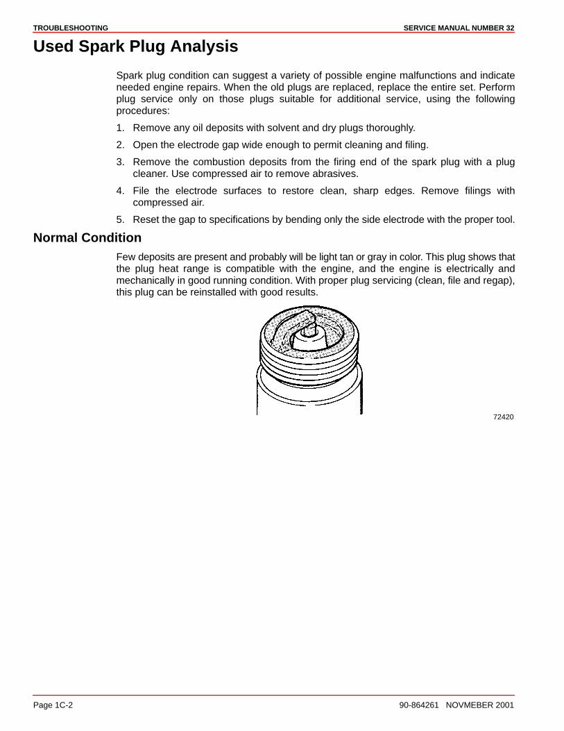
TROUBLESHOOTING SERVICE MANUAL NUMBER 32
Page 1C-2 90-864261 NOVMEBER 2001
Used Spark Plug Analysis
Spark plug condition can suggest a variety of possible engine malfunctions and indicateneeded engine repairs. When the old plugs are replaced, replace the entire set. Performplug service only on those plugs suitable for additional service, using the followingprocedures:
1. Remove any oil deposits with solvent and dry plugs thoroughly.
2. Open the electrode gap wide enough to permit cleaning and filing.
3. Remove the combustion deposits from the firing end of the spark plug with a plugcleaner. Use compressed air to remove abrasives.
4. File the electrode surfaces to restore clean, sharp edges. Remove filings withcompressed air.
5. Reset the gap to specifications by bending only the side electrode with the proper tool.
Normal ConditionFew deposits are present and probably will be light tan or gray in color. This plug shows thatthe plug heat range is compatible with the engine, and the engine is electrically andmechanically in good running condition. With proper plug servicing (clean, file and regap),this plug can be reinstalled with good results.
72420
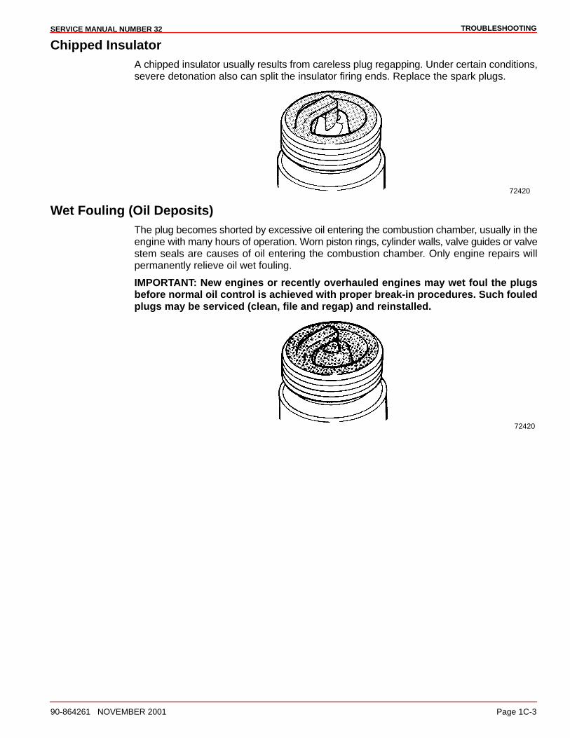
TROUBLESHOOTINGSERVICE MANUAL NUMBER 32
90-864261 NOVEMBER 2001 Page 1C-3
Chipped InsulatorA chipped insulator usually results from careless plug regapping. Under certain conditions,severe detonation also can split the insulator firing ends. Replace the spark plugs.
72420
Wet Fouling (Oil Deposits)The plug becomes shorted by excessive oil entering the combustion chamber, usually in theengine with many hours of operation. Worn piston rings, cylinder walls, valve guides or valvestem seals are causes of oil entering the combustion chamber. Only engine repairs willpermanently relieve oil wet fouling.
IMPORTANT: New engines or recently overhauled engines may wet foul the plugsbefore normal oil control is achieved with proper break-in procedures. Such fouledplugs may be serviced (clean, file and regap) and reinstalled.
72420
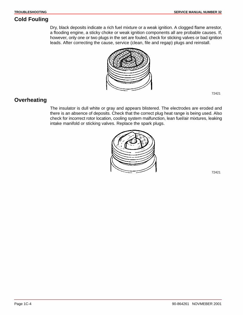
TROUBLESHOOTING SERVICE MANUAL NUMBER 32
Page 1C-4 90-864261 NOVMEBER 2001
Cold FoulingDry, black deposits indicate a rich fuel mixture or a weak ignition. A clogged flame arrestor,a flooding engine, a sticky choke or weak ignition components all are probable causes. If,however, only one or two plugs in the set are fouled, check for sticking valves or bad ignitionleads. After correcting the cause, service (clean, file and regap) plugs and reinstall.
72421
OverheatingThe insulator is dull white or gray and appears blistered. The electrodes are eroded andthere is an absence of deposits. Check that the correct plug heat range is being used. Alsocheck for incorrect rotor location, cooling system malfunction, lean fuel/air mixtures, leakingintake manifold or sticking valves. Replace the spark plugs.
72421
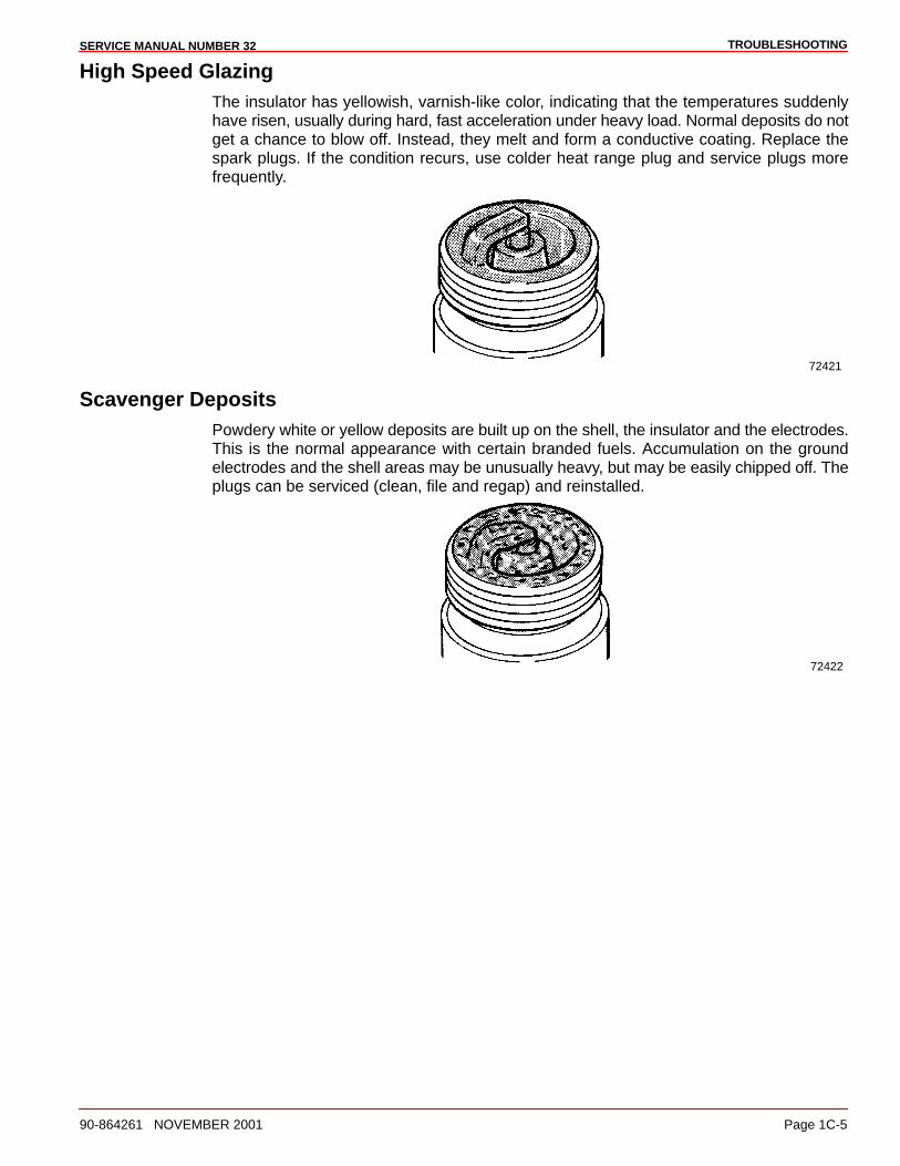
TROUBLESHOOTINGSERVICE MANUAL NUMBER 32
90-864261 NOVEMBER 2001 Page 1C-5
High Speed GlazingThe insulator has yellowish, varnish-like color, indicating that the temperatures suddenlyhave risen, usually during hard, fast acceleration under heavy load. Normal deposits do notget a chance to blow off. Instead, they melt and form a conductive coating. Replace thespark plugs. If the condition recurs, use colder heat range plug and service plugs morefrequently.
72421
Scavenger DepositsPowdery white or yellow deposits are built up on the shell, the insulator and the electrodes.This is the normal appearance with certain branded fuels. Accumulation on the groundelectrodes and the shell areas may be unusually heavy, but may be easily chipped off. Theplugs can be serviced (clean, file and regap) and reinstalled.
72422
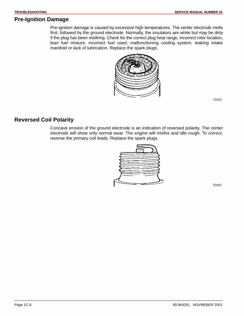
TROUBLESHOOTING SERVICE MANUAL NUMBER 32
Page 1C-6 90-864261 NOVMEBER 2001
Pre-Ignition DamagePre-ignition damage is caused by excessive high temperatures. The center electrode meltsfirst, followed by the ground electrode. Normally, the insulators are white but may be dirtyif the plug has been misfiring. Check for the correct plug heat range, incorrect rotor location,lean fuel mixture, incorrect fuel used, malfunctioning cooling system, leaking intakemanifold or lack of lubrication. Replace the spark plugs.
72422
Reversed Coil PolarityConcave erosion of the ground electrode is an indication of reversed polarity. The centerelectrode will show only normal wear. The engine will misfire and idle rough. To correct,reverse the primary coil leads. Replace the spark plugs.
72422
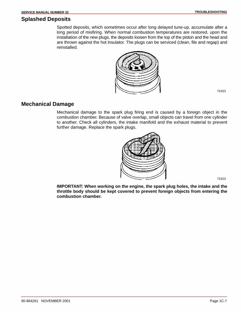
TROUBLESHOOTINGSERVICE MANUAL NUMBER 32
90-864261 NOVEMBER 2001 Page 1C-7
Splashed DepositsSpotted deposits, which sometimes occur after long delayed tune-up, accumulate after along period of misfiring. When normal combustion temperatures are restored, upon theinstallation of the new plugs, the deposits loosen from the top of the piston and the head andare thrown against the hot insulator. The plugs can be serviced (clean, file and regap) andreinstalled.
72423
Mechanical DamageMechanical damage to the spark plug firing end is caused by a foreign object in thecombustion chamber. Because of valve overlap, small objects can travel from one cylinderto another. Check all cylinders, the intake manifold and the exhaust material to preventfurther damage. Replace the spark plugs.
72423
IMPORTANT: When working on the engine, the spark plug holes, the intake and thethrottle body should be kept covered to prevent foreign objects from entering thecombustion chamber.
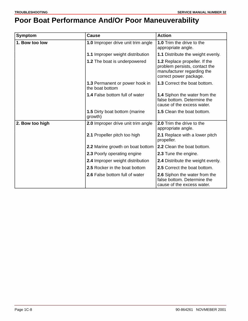
TROUBLESHOOTING SERVICE MANUAL NUMBER 32
Page 1C-8 90-864261 NOVMEBER 2001
Poor Boat Performance And/Or Poor Maneuverability
Symptom Cause Action
1. Bow too low 1.0 Improper drive unit trim angle 1.0 Trim the drive to theappropriate angle.
1.1 Improper weight distribution 1.1 Distribute the weight evenly.
1.2 The boat is underpowered 1.2 Replace propeller. If theproblem persists, contact themanufacturer regarding thecorrect power package.
1.3 Permanent or power hook inthe boat bottom
1.3 Correct the boat bottom.
1.4 False bottom full of water 1.4 Siphon the water from thefalse bottom. Determine thecause of the excess water.
1.5 Dirty boat bottom (marinegrowth)
1.5 Clean the boat bottom.
2. Bow too high 2.0 Improper drive unit trim angle 2.0 Trim the drive to theappropriate angle.
2.1 Propeller pitch too high 2.1 Replace with a lower pitchpropeller.
2.2 Marine growth on boat bottom 2.2 Clean the boat bottom.
2.3 Poorly operating engine 2.3 Tune the engine.
2.4 Improper weight distribution 2.4 Distribute the weight evenly.
2.5 Rocker in the boat bottom 2.5 Correct the boat bottom.
2.6 False bottom full of water 2.6 Siphon the water from thefalse bottom. Determine thecause of the excess water.
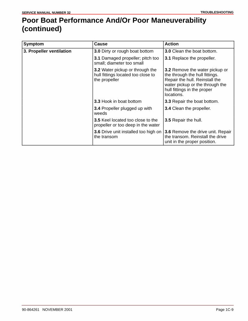
TROUBLESHOOTINGSERVICE MANUAL NUMBER 32
90-864261 NOVEMBER 2001 Page 1C-9
Poor Boat Performance And/Or Poor Maneuverability(continued)
Symptom Cause Action
3. Propeller ventilation 3.0 Dirty or rough boat bottom 3.0 Clean the boat bottom.
3.1 Damaged propeller; pitch toosmall; diameter too small
3.1 Replace the propeller.
3.2 Water pickup or through thehull fittings located too close tothe propeller
3.2 Remove the water pickup orthe through the hull fittings.Repair the hull. Reinstall thewater pickup or the through thehull fittings in the properlocations.
3.3 Hook in boat bottom 3.3 Repair the boat bottom.
3.4 Propeller plugged up withweeds
3.4 Clean the propeller.
3.5 Keel located too close to thepropeller or too deep in the water
3.5 Repair the hull.
3.6 Drive unit installed too high onthe transom
3.6 Remove the drive unit. Repairthe transom. Reinstall the driveunit in the proper position.
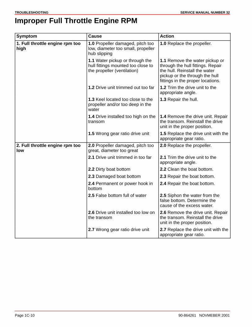
TROUBLESHOOTING SERVICE MANUAL NUMBER 32
Page 1C-10 90-864261 NOVMEBER 2001
Improper Full Throttle Engine RPM
Symptom Cause Action
1. Full throttle engine rpm toohigh
1.0 Propeller damaged, pitch toolow, diameter too small, propellerhub slipping
1.0 Replace the propeller.
1.1 Water pickup or through thehull fittings mounted too close tothe propeller (ventilation)
1.1 Remove the water pickup orthrough the hull fittings. Repairthe hull. Reinstall the waterpickup or the through the hullfittings in the proper locations.
1.2 Drive unit trimmed out too far 1.2 Trim the drive unit to theappropriate angle.
1.3 Keel located too close to thepropeller and/or too deep in thewater
1.3 Repair the hull.
1.4 Drive installed too high on thetransom
1.4 Remove the drive unit. Repairthe transom. Reinstall the driveunit in the proper position.
1.5 Wrong gear ratio drive unit 1.5 Replace the drive unit with theappropriate gear ratio.
2. Full throttle engine rpm toolow
2.0 Propeller damaged, pitch toogreat, diameter too great
2.0 Replace the propeller.
2.1 Drive unit trimmed in too far 2.1 Trim the drive unit to theappropriate angle.
2.2 Dirty boat bottom 2.2 Clean the boat bottom.
2.3 Damaged boat bottom 2.3 Repair the boat bottom.
2.4 Permanent or power hook inbottom
2.4 Repair the boat bottom.
2.5 False bottom full of water 2.5 Siphon the water from thefalse bottom. Determine thecause of the excess water.
2.6 Drive unit installed too low onthe transom
2.6 Remove the drive unit. Repairthe transom. Reinstall the driveunit in the proper position.
2.7 Wrong gear ratio drive unit 2.7 Replace the drive unit with theappropriate gear ratio.
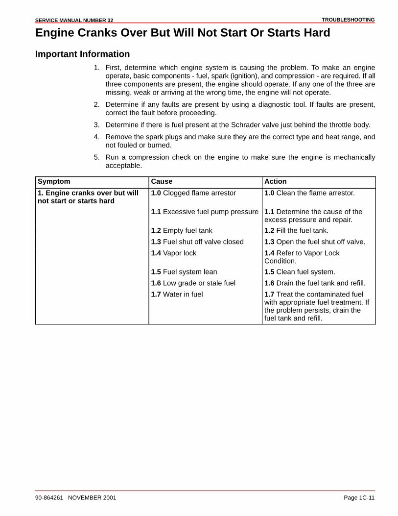
TROUBLESHOOTINGSERVICE MANUAL NUMBER 32
90-864261 NOVEMBER 2001 Page 1C-11
Engine Cranks Over But Will Not Start Or Starts Hard
Important Information1. First, determine which engine system is causing the problem. To make an engine
operate, basic components - fuel, spark (ignition), and compression - are required. If allthree components are present, the engine should operate. If any one of the three aremissing, weak or arriving at the wrong time, the engine will not operate.
2. Determine if any faults are present by using a diagnostic tool. If faults are present,correct the fault before proceeding.
3. Determine if there is fuel present at the Schrader valve just behind the throttle body.
4. Remove the spark plugs and make sure they are the correct type and heat range, andnot fouled or burned.
5. Run a compression check on the engine to make sure the engine is mechanicallyacceptable.
Symptom Cause Action
1. Engine cranks over but willnot start or starts hard
1.0 Clogged flame arrestor 1.0 Clean the flame arrestor.
1.1 Excessive fuel pump pressure 1.1 Determine the cause of theexcess pressure and repair.
1.2 Empty fuel tank 1.2 Fill the fuel tank.
1.3 Fuel shut off valve closed 1.3 Open the fuel shut off valve.
1.4 Vapor lock 1.4 Refer to Vapor LockCondition.
1.5 Fuel system lean 1.5 Clean fuel system.
1.6 Low grade or stale fuel 1.6 Drain the fuel tank and refill.
1.7 Water in fuel 1.7 Treat the contaminated fuelwith appropriate fuel treatment. Ifthe problem persists, drain thefuel tank and refill.

TROUBLESHOOTING SERVICE MANUAL NUMBER 32
Page 1C-12 90-864261 NOVMEBER 2001
Engine Will Not Crank Over
Symptom Cause Action
1. Engine will not crank over. 1.0 Remote control lever not inneutral position
1.0 Place the remote control leverin NEUTRAL and try the ignitionagain. If the problem persists,check the remote control levelNEUTRAL detent setting.
1.1 Battery charge low, damagedwiring, loose electricalconnections
1.1 Check the electricalconnections at the starter.
Check the battery cableconnections.
Check the battery charge andrecharge if necessary.
1.2 Circuit breaker tripped 1.2 Reset the circuit breaker.
1.3 Blown fuse 1.3 Replace the fuse.
1.4 Ignition switch faulty 1.4 Replace the ignition switch.
1.5 Slave solenoid faulty 1.5 Replace the slave solenoid.
1.6 Faulty neutral start safetyswitch
1.6 Replace the neutral startsafety switch.
1.7 Starter solenoid faulty 1.7 Replace the starter solenoid.
1.8 Starter motor faulty 1.8 Replace the starter motor.
1.9 Mechanical enginemalfunction
1.9 Determine the cause of themalfunction and repair.
1.10 Lanyard stop switchactivated
1.10 Deactivate the lanyard stopswitch
Charging System Inoperative
Symptom Cause Action
1. Charging system inoperative 1.0 Loose or broken drive belt 1.0 Replace the serpentine drivebelt.
1.1 Engine rpm too low on initialstart
1.1 Accelerate the engine to 1500rpm.
1.2 Loose or corroded electricalconnections
1.2 Check the electricalconnections.
1.3 Faulty battery gauge 1.3 Replace the gauge.
1.4 Battery will not accept charge 1.4 Check the electrolyte leveland fill if necessary. Replace thebattery.
1.5 Faulty alternator or regulator 1.5 Test the alternator and theregulator and replace ifnecessary.
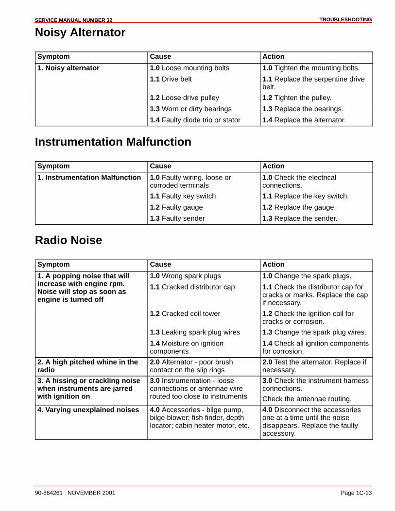
TROUBLESHOOTINGSERVICE MANUAL NUMBER 32
90-864261 NOVEMBER 2001 Page 1C-13
Noisy Alternator
Symptom Cause Action
1. Noisy alternator 1.0 Loose mounting bolts 1.0 Tighten the mounting bolts.
1.1 Drive belt 1.1 Replace the serpentine drivebelt.
1.2 Loose drive pulley 1.2 Tighten the pulley.
1.3 Worn or dirty bearings 1.3 Replace the bearings.
1.4 Faulty diode trio or stator 1.4 Replace the alternator.
Instrumentation Malfunction
Symptom Cause Action
1. Instrumentation Malfunction 1.0 Faulty wiring, loose orcorroded terminals
1.0 Check the electricalconnections.
1.1 Faulty key switch 1.1 Replace the key switch.
1.2 Faulty gauge 1.2 Replace the gauge.
1.3 Faulty sender 1.3 Replace the sender.
Radio Noise
Symptom Cause Action
1. A popping noise that will 1.0 Wrong spark plugs 1.0 Change the spark plugs.increase with engine rpm.Noise will stop as soon asengine is turned off
1.1 Cracked distributor cap 1.1 Check the distributor cap forcracks or marks. Replace the capif necessary.
1.2 Cracked coil tower 1.2 Check the ignition coil forcracks or corrosion.
1.3 Leaking spark plug wires 1.3 Change the spark plug wires.
1.4 Moisture on ignitioncomponents
1.4 Check all ignition componentsfor corrosion.
2. A high pitched whine in theradio
2.0 Alternator - poor brushcontact on the slip rings
2.0 Test the alternator. Replace ifnecessary.
3. A hissing or crackling noisewhen instruments are jarredwith ignition on
3.0 Instrumentation - looseconnections or antennae wirerouted too close to instruments
3.0 Check the instrument harnessconnections.
Check the antennae routing.
4. Varying unexplained noises 4.0 Accessories - bilge pump,bilge blower; fish finder, depthlocator; cabin heater motor, etc.
4.0 Disconnect the accessoriesone at a time until the noisedisappears. Replace the faultyaccessory.
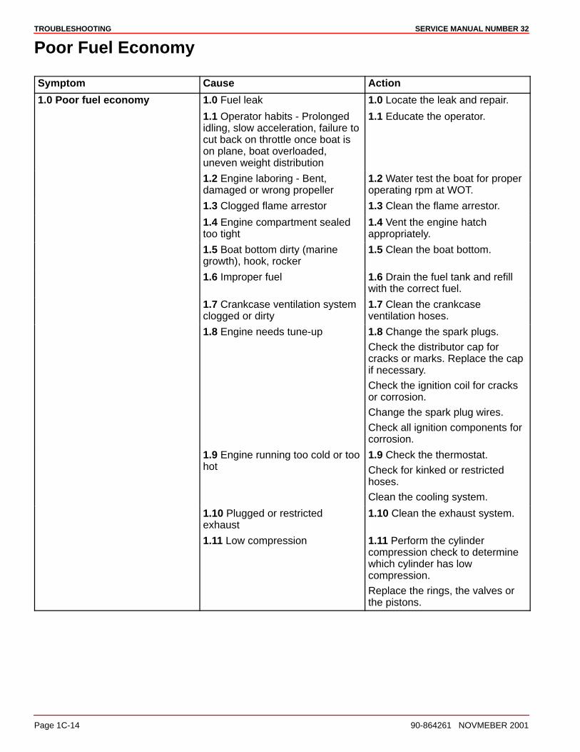
TROUBLESHOOTING SERVICE MANUAL NUMBER 32
Page 1C-14 90-864261 NOVMEBER 2001
Poor Fuel Economy
Symptom Cause Action
1.0 Poor fuel economy 1.0 Fuel leak 1.0 Locate the leak and repair.
1.1 Operator habits - Prolongedidling, slow acceleration, failure tocut back on throttle once boat ison plane, boat overloaded,uneven weight distribution
1.1 Educate the operator.
1.2 Engine laboring - Bent,damaged or wrong propeller
1.2 Water test the boat for properoperating rpm at WOT.
1.3 Clogged flame arrestor 1.3 Clean the flame arrestor.
1.4 Engine compartment sealedtoo tight
1.4 Vent the engine hatchappropriately.
1.5 Boat bottom dirty (marinegrowth), hook, rocker
1.5 Clean the boat bottom.
1.6 Improper fuel 1.6 Drain the fuel tank and refillwith the correct fuel.
1.7 Crankcase ventilation systemclogged or dirty
1.7 Clean the crankcaseventilation hoses.
1.8 Engine needs tune-up 1.8 Change the spark plugs.
Check the distributor cap forcracks or marks. Replace the capif necessary.
Check the ignition coil for cracksor corrosion.
Change the spark plug wires.
Check all ignition components forcorrosion.
1.9 Engine running too cold or toohot
1.9 Check the thermostat.
Check for kinked or restrictedhoses.
Clean the cooling system.
1.10 Plugged or restrictedexhaust
1.10 Clean the exhaust system.
1.11 Low compression 1.11 Perform the cylindercompression check to determinewhich cylinder has lowcompression.
Replace the rings, the valves orthe pistons.
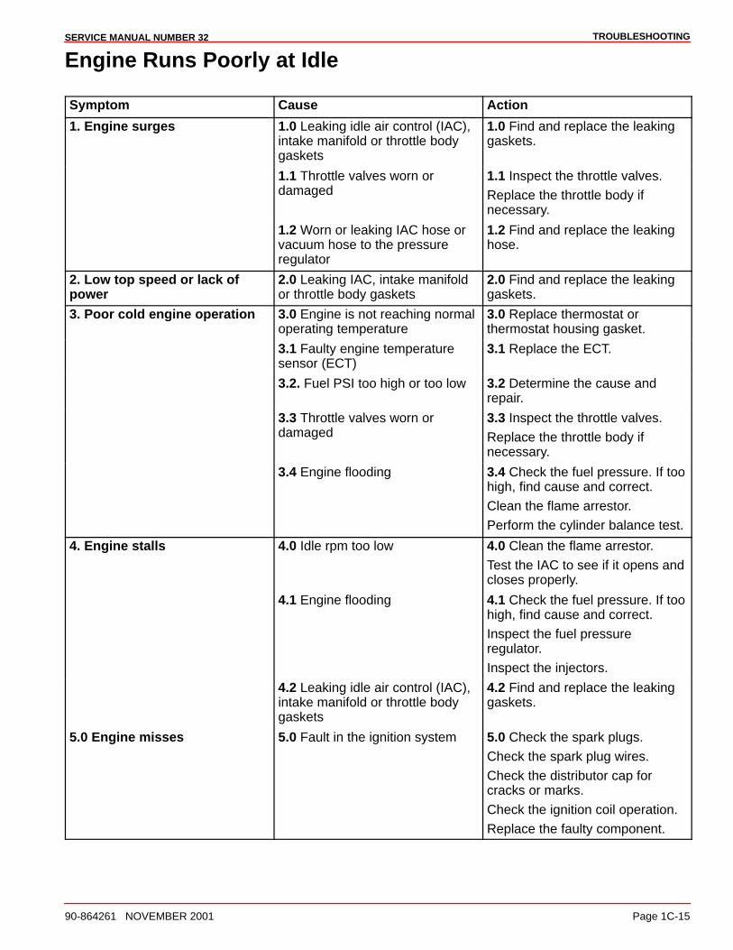
TROUBLESHOOTINGSERVICE MANUAL NUMBER 32
90-864261 NOVEMBER 2001 Page 1C-15
Engine Runs Poorly at Idle
Symptom Cause Action
1. Engine surges 1.0 Leaking idle air control (IAC),intake manifold or throttle bodygaskets
1.0 Find and replace the leakinggaskets.
1.1 Throttle valves worn ordamaged
1.1 Inspect the throttle valves.
Replace the throttle body ifnecessary.
1.2 Worn or leaking IAC hose orvacuum hose to the pressureregulator
1.2 Find and replace the leakinghose.
2. Low top speed or lack ofpower
2.0 Leaking IAC, intake manifoldor throttle body gaskets
2.0 Find and replace the leakinggaskets.
3. Poor cold engine operation 3.0 Engine is not reaching normaloperating temperature
3.0 Replace thermostat orthermostat housing gasket.
3.1 Faulty engine temperaturesensor (ECT)
3.1 Replace the ECT.
3.2. Fuel PSI too high or too low 3.2 Determine the cause andrepair.
3.3 Throttle valves worn ordamaged
3.3 Inspect the throttle valves.
Replace the throttle body ifnecessary.
3.4 Engine flooding 3.4 Check the fuel pressure. If toohigh, find cause and correct.
Clean the flame arrestor.
Perform the cylinder balance test.
4. Engine stalls 4.0 Idle rpm too low 4.0 Clean the flame arrestor.
Test the IAC to see if it opens andcloses properly.
4.1 Engine flooding 4.1 Check the fuel pressure. If toohigh, find cause and correct.
Inspect the fuel pressureregulator.
Inspect the injectors.
4.2 Leaking idle air control (IAC),intake manifold or throttle bodygaskets
4.2 Find and replace the leakinggaskets.
5.0 Engine misses 5.0 Fault in the ignition system 5.0 Check the spark plugs.
Check the spark plug wires.
Check the distributor cap forcracks or marks.
Check the ignition coil operation.
Replace the faulty component.
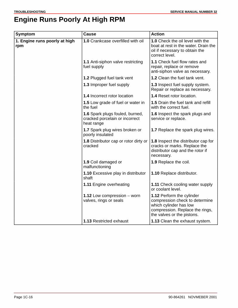
TROUBLESHOOTING SERVICE MANUAL NUMBER 32
Page 1C-16 90-864261 NOVMEBER 2001
Engine Runs Poorly At High RPM
Symptom Cause Action
1. Engine runs poorly at highrpm
1.0 Crankcase overfilled with oil 1.0 Check the oil level with theboat at rest in the water. Drain theoil if necessary to obtain thecorrect level.
1.1 Anti-siphon valve restrictingfuel supply
1.1 Check fuel flow rates andrepair, replace or removeanti-siphon valve as necessary.
1.2 Plugged fuel tank vent 1.2 Clean the fuel tank vent.
1.3 Improper fuel supply 1.3 Inspect fuel supply system.Repair or replace as necessary.
1.4 Incorrect rotor location 1.4 Reset rotor location.
1.5 Low grade of fuel or water inthe fuel
1.5 Drain the fuel tank and refillwith the correct fuel.
1.6 Spark plugs fouled, burned,cracked porcelain or incorrectheat range
1.6 Inspect the spark plugs andservice or replace.
1.7 Spark plug wires broken orpoorly insulated
1.7 Replace the spark plug wires.
1.8 Distributor cap or rotor dirty orcracked
1.8 Inspect the distributor cap forcracks or marks. Replace thedistributor cap and the rotor ifnecessary.
1.9 Coil damaged ormalfunctioning
1.9 Replace the coil.
1.10 Excessive play in distributorshaft
1.10 Replace distributor.
1.11 Engine overheating 1.11 Check cooling water supplyor coolant level.
1.12 Low compression – wornvalves, rings or seals
1.12 Perform the cylindercompression check to determinewhich cylinder has lowcompression. Replace the rings,the valves or the pistons.
1.13 Restricted exhaust 1.13 Clean the exhaust system.
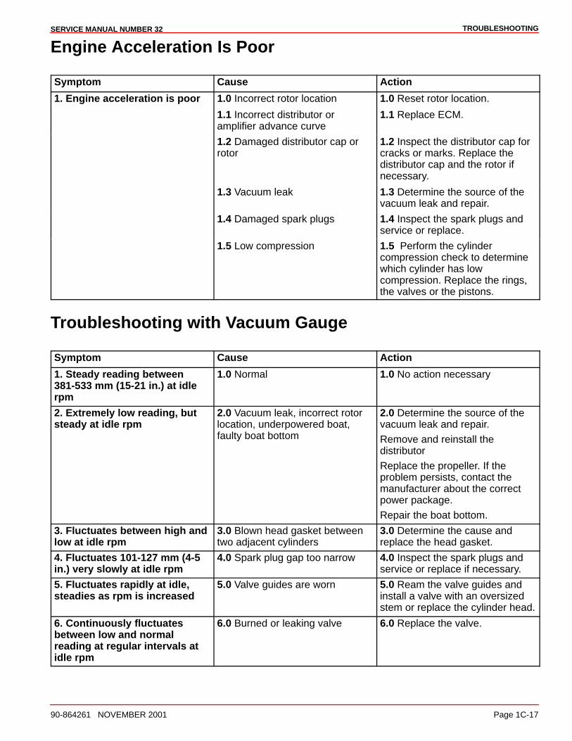
TROUBLESHOOTINGSERVICE MANUAL NUMBER 32
90-864261 NOVEMBER 2001 Page 1C-17
Engine Acceleration Is Poor
Symptom Cause Action
1. Engine acceleration is poor 1.0 Incorrect rotor location 1.0 Reset rotor location.
1.1 Incorrect distributor oramplifier advance curve
1.1 Replace ECM.
1.2 Damaged distributor cap orrotor
1.2 Inspect the distributor cap forcracks or marks. Replace thedistributor cap and the rotor ifnecessary.
1.3 Vacuum leak 1.3 Determine the source of thevacuum leak and repair.
1.4 Damaged spark plugs 1.4 Inspect the spark plugs andservice or replace.
1.5 Low compression 1.5 Perform the cylindercompression check to determinewhich cylinder has lowcompression. Replace the rings,the valves or the pistons.
Troubleshooting with Vacuum Gauge
Symptom Cause Action
1. Steady reading between381-533 mm (15-21 in.) at idlerpm
1.0 Normal 1.0 No action necessary
2. Extremely low reading, butsteady at idle rpm
2.0 Vacuum leak, incorrect rotorlocation, underpowered boat,faulty boat bottom
2.0 Determine the source of thevacuum leak and repair.
Remove and reinstall thedistributor
Replace the propeller. If theproblem persists, contact themanufacturer about the correctpower package.
Repair the boat bottom.
3. Fluctuates between high andlow at idle rpm
3.0 Blown head gasket betweentwo adjacent cylinders
3.0 Determine the cause andreplace the head gasket.
4. Fluctuates 101-127 mm (4-5in.) very slowly at idle rpm
4.0 Spark plug gap too narrow 4.0 Inspect the spark plugs andservice or replace if necessary.
5. Fluctuates rapidly at idle,steadies as rpm is increased
5.0 Valve guides are worn 5.0 Ream the valve guides andinstall a valve with an oversizedstem or replace the cylinder head.
6. Continuously fluctuatesbetween low and normalreading at regular intervals atidle rpm
6.0 Burned or leaking valve 6.0 Replace the valve.
TROUBLESHOOTING SERVICE MANUAL NUMBER 32
Page 1C-18 90-864261 NOVMEBER 2001
Engine Noise
Important InformationNo definite rule or test will positively determine the source of engine noise. Use the followinginformation only as a general guide to engine noise diagnosis.
1. Use a timing light to determine if the noise is timed with engine speed or 1/2 enginespeed. Noises timed with engine speed are related to the crankshaft, rods, pistons,piston pins and flywheel. Noises timed to 1/2 engine speed are valve train related.
2. The use of a stethoscope can aid in locating a noise source; however, because noisewill travel to other metal parts not involved in the problem, caution must be exercised.
3. If you believe the noise is confined to one particular cylinder, ground spark plug leadsone at a time. If the noise lessens noticeably or disappears, it is isolated to that particularcylinder.
4. Try to isolate the noise to a location in the engine: front to back, top to bottom. This canhelp determine which components are at fault.
5. Sometimes noises can be caused by moving parts coming in contact with othercomponents. Examples are: the flywheel or coupler; the exhaust flappers rattlingagainst exhaust pipe; the crankshaft striking the oil pan, oil pan baffle or dipstick tube;the rocker arm striking the valve cover or a loose flywheel cover. In many cases, if thisis found to be the problem a complete engine teardown is not necessary.
6. When the noise is isolated to a certain area and component, removal and inspection willbe required. Refer to the appropriate sections of the service manual for the informationrequired for service.
7. If the noise cannot be distinguished between the engine and the drive unit, remove thedrive from the boat. Supplying water directly to the engine, operate the engine withoutthe drive to determine whether the noise still occurs.
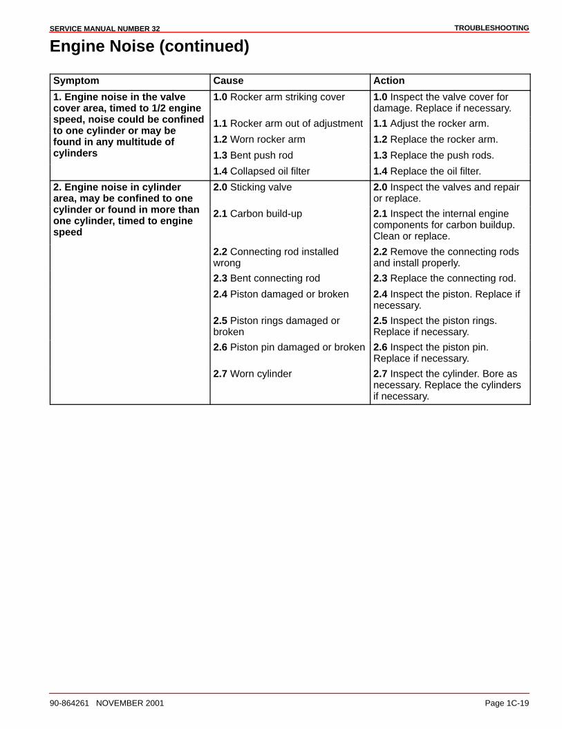
TROUBLESHOOTINGSERVICE MANUAL NUMBER 32
90-864261 NOVEMBER 2001 Page 1C-19
Engine Noise (continued)
Symptom Cause Action
1. Engine noise in the valvecover area, timed to 1/2 engine
1.0 Rocker arm striking cover 1.0 Inspect the valve cover fordamage. Replace if necessary.
speed, noise could be confined 1.1 Rocker arm out of adjustment 1.1 Adjust the rocker arm.to one cylinder or may befound in any multitude of 1.2 Worn rocker arm 1.2 Replace the rocker arm.cylinders 1.3 Bent push rod 1.3 Replace the push rods.
1.4 Collapsed oil filter 1.4 Replace the oil filter.
2. Engine noise in cylinderarea, may be confined to one
2.0 Sticking valve 2.0 Inspect the valves and repairor replace.
cylinder or found in more thanone cylinder, timed to enginespeed
2.1 Carbon build-up 2.1 Inspect the internal enginecomponents for carbon buildup.Clean or replace.
2.2 Connecting rod installedwrong
2.2 Remove the connecting rodsand install properly.
2.3 Bent connecting rod 2.3 Replace the connecting rod.
2.4 Piston damaged or broken 2.4 Inspect the piston. Replace ifnecessary.
2.5 Piston rings damaged orbroken
2.5 Inspect the piston rings.Replace if necessary.
2.6 Piston pin damaged or broken 2.6 Inspect the piston pin.Replace if necessary.
2.7 Worn cylinder 2.7 Inspect the cylinder. Bore asnecessary. Replace the cylindersif necessary.
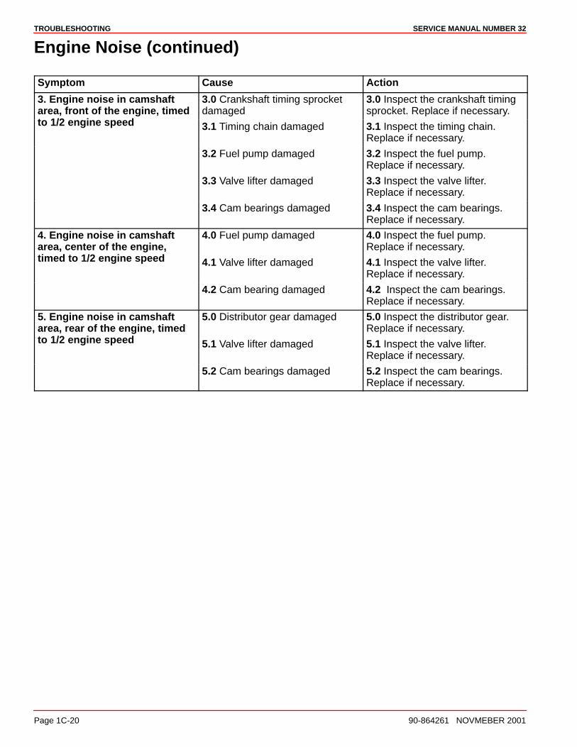
TROUBLESHOOTING SERVICE MANUAL NUMBER 32
Page 1C-20 90-864261 NOVMEBER 2001
Engine Noise (continued)
Symptom Cause Action
3. Engine noise in camshaftarea, front of the engine, timed
3.0 Crankshaft timing sprocketdamaged
3.0 Inspect the crankshaft timingsprocket. Replace if necessary.
to 1/2 engine speed 3.1 Timing chain damaged 3.1 Inspect the timing chain.Replace if necessary.
3.2 Fuel pump damaged 3.2 Inspect the fuel pump.Replace if necessary.
3.3 Valve lifter damaged 3.3 Inspect the valve lifter.Replace if necessary.
3.4 Cam bearings damaged 3.4 Inspect the cam bearings.Replace if necessary.
4. Engine noise in camshaftarea, center of the engine,
4.0 Fuel pump damaged 4.0 Inspect the fuel pump.Replace if necessary.
timed to 1/2 engine speed 4.1 Valve lifter damaged 4.1 Inspect the valve lifter.Replace if necessary.
4.2 Cam bearing damaged 4.2 Inspect the cam bearings.Replace if necessary.
5. Engine noise in camshaftarea, rear of the engine, timed
5.0 Distributor gear damaged 5.0 Inspect the distributor gear.Replace if necessary.
to 1/2 engine speed 5.1 Valve lifter damaged 5.1 Inspect the valve lifter.Replace if necessary.
5.2 Cam bearings damaged 5.2 Inspect the cam bearings.Replace if necessary.
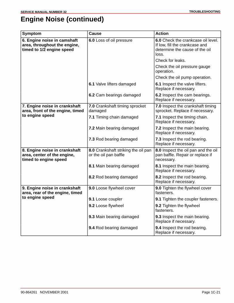
TROUBLESHOOTINGSERVICE MANUAL NUMBER 32
90-864261 NOVEMBER 2001 Page 1C-21
Engine Noise (continued)
Symptom Cause Action
6. Engine noise in camshaftarea, throughout the engine,timed to 1/2 engine speed
6.0 Loss of oil pressure 6.0 Check the crankcase oil level.If low, fill the crankcase anddetermine the cause of the oilloss.
Check for leaks.
Check the oil pressure gaugeoperation.
Check the oil pump operation.
6.1 Valve lifters damaged 6.1 Inspect the valve lifters.Replace if necessary.
6.2 Cam bearings damaged 6.2 Inspect the cam bearings.Replace if necessary.
7. Engine noise in crankshaftarea, front of the engine, timed
7.0 Crankshaft timing sprocketdamaged
7.0 Inspect the crankshaft timingsprocket. Replace if necessary.
to engine speed 7.1 Timing chain damaged 7.1 Inspect the timing chain.Replace if necessary.
7.2 Main bearing damaged 7.2 Inspect the main bearing.Replace if necessary.
7.3 Rod bearing damaged 7.3 Inspect the rod bearing.Replace if necessary.
8. Engine noise in crankshaftarea, center of the engine,timed to engine speed
8.0 Crankshaft striking the oil panor the oil pan baffle
8.0 Inspect the oil pan and the oilpan baffle. Repair or replace ifnecessary.
8.1 Main bearing damaged 8.1 Inspect the main bearing.Replace if necessary.
8.2 Rod bearing damaged 8.2 Inspect the rod bearing.Replace if necessary.
9. Engine noise in crankshaftarea, rear of the engine, timed
9.0 Loose flywheel cover 9.0 Tighten the flywheel coverfasteners.
to engine speed 9.1 Loose coupler 9.1 Tighten the coupler fasteners.
9.2 Loose flywheel 9.2 Tighten the flywheelfasteners.
9.3 Main bearing damaged 9.3 Inspect the main bearing.Replace if necessary.
9.4 Rod bearing damaged 9.4 Inspect the rod bearing.Replace if necessary.
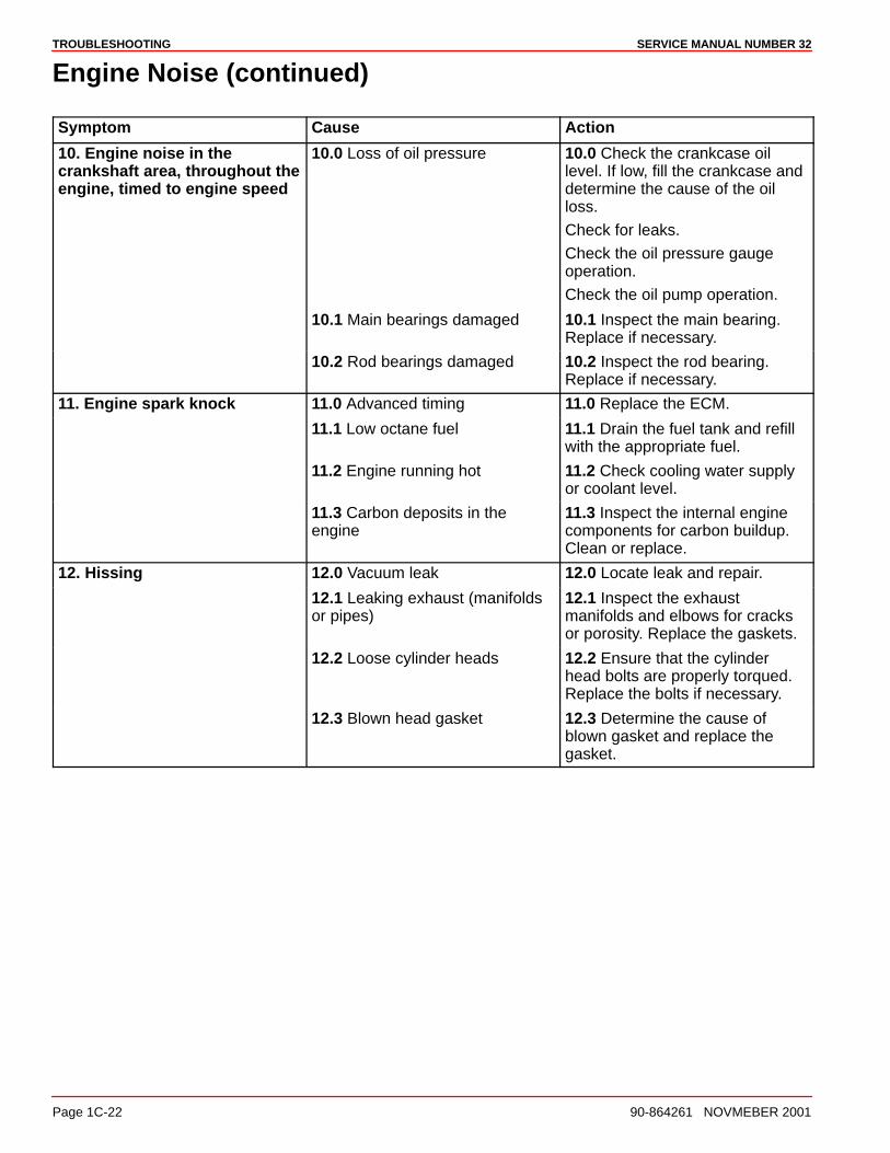
TROUBLESHOOTING SERVICE MANUAL NUMBER 32
Page 1C-22 90-864261 NOVMEBER 2001
Engine Noise (continued)
Symptom Cause Action
10. Engine noise in thecrankshaft area, throughout theengine, timed to engine speed
10.0 Loss of oil pressure 10.0 Check the crankcase oillevel. If low, fill the crankcase anddetermine the cause of the oilloss.
Check for leaks.
Check the oil pressure gaugeoperation.
Check the oil pump operation.
10.1 Main bearings damaged 10.1 Inspect the main bearing.Replace if necessary.
10.2 Rod bearings damaged 10.2 Inspect the rod bearing.Replace if necessary.
11. Engine spark knock 11.0 Advanced timing 11.0 Replace the ECM.
11.1 Low octane fuel 11.1 Drain the fuel tank and refillwith the appropriate fuel.
11.2 Engine running hot 11.2 Check cooling water supplyor coolant level.
11.3 Carbon deposits in theengine
11.3 Inspect the internal enginecomponents for carbon buildup.Clean or replace.
12. Hissing 12.0 Vacuum leak 12.0 Locate leak and repair.
12.1 Leaking exhaust (manifoldsor pipes)
12.1 Inspect the exhaustmanifolds and elbows for cracksor porosity. Replace the gaskets.
12.2 Loose cylinder heads 12.2 Ensure that the cylinderhead bolts are properly torqued.Replace the bolts if necessary.
12.3 Blown head gasket 12.3 Determine the cause ofblown gasket and replace thegasket.
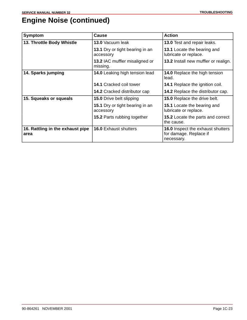
TROUBLESHOOTINGSERVICE MANUAL NUMBER 32
90-864261 NOVEMBER 2001 Page 1C-23
Engine Noise (continued)
Symptom Cause Action
13. Throttle Body Whistle 13.0 Vacuum leak 13.0 Test and repair leaks.
13.1 Dry or tight bearing in anaccessory
13.1 Locate the bearing andlubricate or replace.
13.2 IAC muffler misaligned ormissing.
13.2 Install new muffler or realign.
14. Sparks jumping 14.0 Leaking high tension lead 14.0 Replace the high tensionlead.
14.1 Cracked coil tower 14.1 Replace the ignition coil.
14.2 Cracked distributor cap 14.2 Replace the distributor cap.
15. Squeaks or squeals 15.0 Drive belt slipping 15.0 Replace the drive belt.
15.1 Dry or tight bearing in anaccessory
15.1 Locate the bearing andlubricate or replace.
15.2 Parts rubbing together 15.2 Locate the parts and correctthe cause.
16. Rattling in the exhaust pipearea
16.0 Exhaust shutters 16.0 Inspect the exhaust shuttersfor damage. Replace ifnecessary.
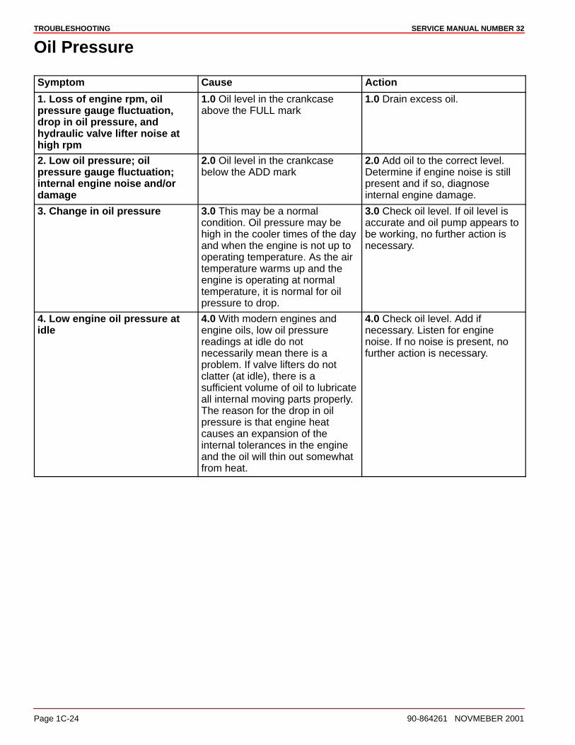
TROUBLESHOOTING SERVICE MANUAL NUMBER 32
Page 1C-24 90-864261 NOVMEBER 2001
Oil Pressure
Symptom Cause Action
1. Loss of engine rpm, oilpressure gauge fluctuation,drop in oil pressure, andhydraulic valve lifter noise athigh rpm
1.0 Oil level in the crankcaseabove the FULL mark
1.0 Drain excess oil.
2. Low oil pressure; oilpressure gauge fluctuation;internal engine noise and/ordamage
2.0 Oil level in the crankcasebelow the ADD mark
2.0 Add oil to the correct level.Determine if engine noise is stillpresent and if so, diagnoseinternal engine damage.
3. Change in oil pressure 3.0 This may be a normalcondition. Oil pressure may behigh in the cooler times of the dayand when the engine is not up tooperating temperature. As the airtemperature warms up and theengine is operating at normaltemperature, it is normal for oilpressure to drop.
3.0 Check oil level. If oil level isaccurate and oil pump appears tobe working, no further action isnecessary.
4. Low engine oil pressure atidle
4.0 With modern engines andengine oils, low oil pressurereadings at idle do notnecessarily mean there is aproblem. If valve lifters do notclatter (at idle), there is asufficient volume of oil to lubricateall internal moving parts properly.The reason for the drop in oilpressure is that engine heatcauses an expansion of theinternal tolerances in the engineand the oil will thin out somewhatfrom heat.
4.0 Check oil level. Add ifnecessary. Listen for enginenoise. If no noise is present, nofurther action is necessary.
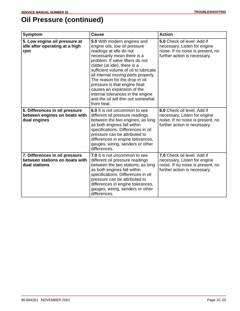
TROUBLESHOOTINGSERVICE MANUAL NUMBER 32
90-864261 NOVEMBER 2001 Page 1C-25
Oil Pressure (continued)
Symptom Cause Action
5. Low engine oil pressure atidle after operating at a highrpm
5.0 With modern engines andengine oils, low oil pressurereadings at idle do notnecessarily mean there is aproblem. If valve lifters do notclatter (at idle), there is asufficient volume of oil to lubricateall internal moving parts properly.The reason for the drop in oilpressure is that engine heatcauses an expansion of theinternal tolerances in the engineand the oil will thin out somewhatfrom heat.
5.0 Check oil level. Add ifnecessary. Listen for enginenoise. If no noise is present, nofurther action is necessary.
6. Differences in oil pressurebetween engines on boats withdual engines
6.0 It is not uncommon to seedifferent oil pressure readingsbetween the two engines, as longas both engines fall withinspecifications. Differences in oilpressure can be attributed todifferences in engine tolerances,gauges, wiring, senders or otherdifferences.
6.0 Check oil level. Add ifnecessary. Listen for enginenoise. If no noise is present, nofurther action is necessary.
7. Differences in oil pressurebetween stations on boats withdual stations
7.0 It is not uncommon to seedifferent oil pressure readingsbetween the two stations, as longas both engines fall withinspecifications. Differences in oilpressure can be attributed todifferences in engine tolerances,gauges, wiring, senders or otherdifferences.
7.0 Check oil level. Add ifnecessary. Listen for enginenoise. If no noise is present, nofurther action is necessary.
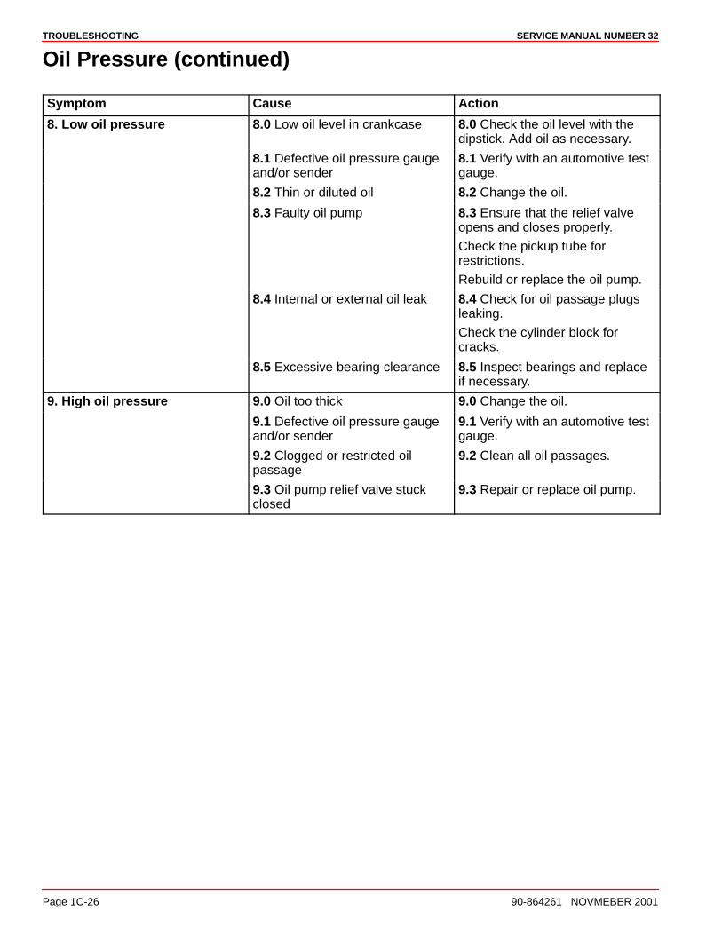
TROUBLESHOOTING SERVICE MANUAL NUMBER 32
Page 1C-26 90-864261 NOVMEBER 2001
Oil Pressure (continued)
Symptom Cause Action
8. Low oil pressure 8.0 Low oil level in crankcase 8.0 Check the oil level with thedipstick. Add oil as necessary.
8.1 Defective oil pressure gaugeand/or sender
8.1 Verify with an automotive testgauge.
8.2 Thin or diluted oil 8.2 Change the oil.
8.3 Faulty oil pump 8.3 Ensure that the relief valveopens and closes properly.
Check the pickup tube forrestrictions.
Rebuild or replace the oil pump.
8.4 Internal or external oil leak 8.4 Check for oil passage plugsleaking.
Check the cylinder block forcracks.
8.5 Excessive bearing clearance 8.5 Inspect bearings and replaceif necessary.
9. High oil pressure 9.0 Oil too thick 9.0 Change the oil.
9.1 Defective oil pressure gaugeand/or sender
9.1 Verify with an automotive testgauge.
9.2 Clogged or restricted oilpassage
9.2 Clean all oil passages.
9.3 Oil pump relief valve stuckclosed
9.3 Repair or replace oil pump.
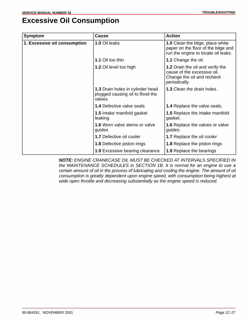
TROUBLESHOOTINGSERVICE MANUAL NUMBER 32
90-864261 NOVEMBER 2001 Page 1C-27
Excessive Oil Consumption
Symptom Cause Action
1. Excessive oil consumption 1.0 Oil leaks 1.0 Clean the bilge, place whitepaper on the floor of the bilge andrun the engine to locate oil leaks.
1.1 Oil too thin 1.1 Change the oil.
1.2 Oil level too high 1.2 Drain the oil and verify thecause of the excessive oil.Change the oil and recheckperiodically.
1.3 Drain holes in cylinder headplugged causing oil to flood thevalves
1.3 Clean the drain holes.
1.4 Defective valve seals 1.4 Replace the valve seals.
1.5 Intake manifold gasketleaking
1.5 Replace the intake manifoldgasket.
1.6 Worn valve stems or valveguides
1.6 Replace the valves or valveguides.
1.7 Defective oil cooler 1.7 Replace the oil cooler
1.8 Defective piston rings 1.8 Replace the piston rings
1.9 Excessive bearing clearance 1.9 Replace the bearings
NOTE: ENGINE CRANKCASE OIL MUST BE CHECKED AT INTERVALS SPECIFIED INthe MAINTENANCE SCHEDULES in SECTION 1B. It is normal for an engine to use acertain amount of oil in the process of lubricating and cooling the engine. The amount of oilconsumption is greatly dependent upon engine speed, with consumption being highest atwide open throttle and decreasing substantially as the engine speed is reduced.
TROUBLESHOOTING SERVICE MANUAL NUMBER 32
Page 1C-28 90-864261 NOVMEBER 2001
Water In The Engine
Important InformationIMPORTANT: First determine the location of the water in the engine. This informationcan be of great help when trying to determine where the water came from and howit got into the engine. The three most common problems are: water on top of thepistons, water in the crankcase oil and when both of those conditions occursimultaneously.
1. After locating the water, remove all the water from the engine by removing all the sparkplugs and cranking the engine over to pump out the cylinders.
2. Change the oil and the filter.
3. Start the engine and see if the problem can be duplicated. If the problem can be dupli-cated, a mechanical problem exists. If the problem cannot be duplicated, the problemis either an operator error or a problem that exists only under certain environmental con-ditions.
If the water is contained to the cylinders only, it is usually entering through the intake system,the exhaust system or the head gasket.
If the water is contained to the crankcase only, it is usually caused by a cracked or porousblock, a flooded bilge or condensation.
If the water is located in both the cylinders and the crankcase, it is usually caused by waterin the cylinders getting past the rings and valves or complete submersion.
Checking for rust in the intake manifold or the exhaust manifolds is a good idea. Rust is aclue that the water entered these areas.

TROUBLESHOOTINGSERVICE MANUAL NUMBER 32
90-864261 NOVEMBER 2001 Page 1C-29
Water In Engine (continued)
Symptom Cause Action
1. Water on top of the pistons 1.0 The operator shut the engineoff at a high rpm
1.0 Read and follow theprocedures in the OperationGuide.
1.1 Engine diesels or tries to runbackwards
1.1 Adjust the throttle cable.
Ensure engine idles properly.
1.2 Rain water dripping into theflame arrestor
1.2 Replace the engine cover.
1.3 Spark plug misfiring 1.3 Inspect and service the sparkplugs.
Replace if necessary.
1.4 Backwash through theexhaust system
1.4 Repair the exhaust system.
1.5 Improper engine or exhausthose installation
1.5 Check the engine installationspecifications.
1.6 Cracked exhaust manifold 1.6 Replace the exhaustmanifold.
1.7 Improper manifold to elbowgasket installation
1.7 Replace the manifold to elbowgasket.
1.8 Loose cylinder head bolts 1.8 Tighten the cylinder headbolts.
1.9 Blown cylinder head gasket 1.9 Determine the cause of blowngasket and replace the gasket.
1.10 Cracked valve seat 1.10 Replace the valves.
1.11 Porous or cracked casting 1.11 Inspect and repair or replaceas necessary.
2. Water in crankcase oil 2.0 Water in boat bilge 2.0 Drain the water from the bilge.
2.1 Water seeping past the pistonrings or valves
2.1 Replace the piston rings orthe valves.
2.2 Engine operating cold 2.2 Replace the thermostat.
2.3 Intake manifold leaking near awater passage
2.3 Inspect the intake manifold forcracks. Check the gaskets.
2.4 Cracked or porous casting 2.4 Check the cylinder head, thecylinder block and the intakemanifold for cracks or porosity.
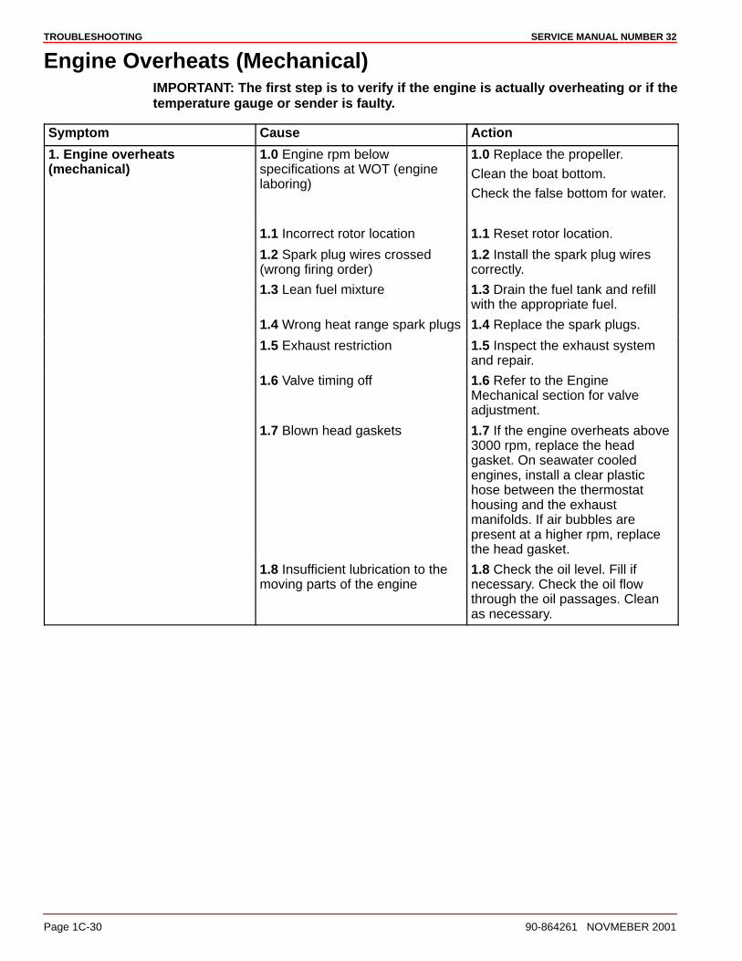
TROUBLESHOOTING SERVICE MANUAL NUMBER 32
Page 1C-30 90-864261 NOVMEBER 2001
Engine Overheats (Mechanical)IMPORTANT: The first step is to verify if the engine is actually overheating or if thetemperature gauge or sender is faulty.
Symptom Cause Action
1. Engine overheats(mechanical)
1.0 Engine rpm belowspecifications at WOT (enginelaboring)
1.0 Replace the propeller.
Clean the boat bottom.
Check the false bottom for water.
1.1 Incorrect rotor location 1.1 Reset rotor location.
1.2 Spark plug wires crossed(wrong firing order)
1.2 Install the spark plug wirescorrectly.
1.3 Lean fuel mixture 1.3 Drain the fuel tank and refillwith the appropriate fuel.
1.4 Wrong heat range spark plugs 1.4 Replace the spark plugs.
1.5 Exhaust restriction 1.5 Inspect the exhaust systemand repair.
1.6 Valve timing off 1.6 Refer to the EngineMechanical section for valveadjustment.
1.7 Blown head gaskets 1.7 If the engine overheats above3000 rpm, replace the headgasket. On seawater cooledengines, install a clear plastichose between the thermostathousing and the exhaustmanifolds. If air bubbles arepresent at a higher rpm, replacethe head gasket.
1.8 Insufficient lubrication to themoving parts of the engine
1.8 Check the oil level. Fill ifnecessary. Check the oil flowthrough the oil passages. Cleanas necessary.
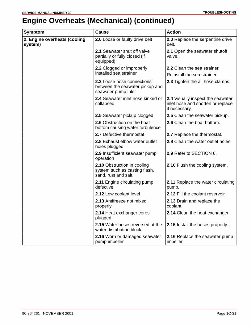
TROUBLESHOOTINGSERVICE MANUAL NUMBER 32
90-864261 NOVEMBER 2001 Page 1C-31
Engine Overheats (Mechanical) (continued)Symptom Cause Action
2. Engine overheats (coolingsystem)
2.0 Loose or faulty drive belt 2.0 Replace the serpentine drivebelt.
2.1 Seawater shut off valvepartially or fully closed (ifequipped)
2.1 Open the seawater shutoffvalve.
2.2 Clogged or improperlyinstalled sea strainer
2.2 Clean the sea strainer.
Reinstall the sea strainer.
2.3 Loose hose connectionsbetween the seawater pickup andseawater pump inlet
2.3 Tighten the all hose clamps.
2.4 Seawater inlet hose kinked orcollapsed
2.4 Visually inspect the seawaterinlet hose and shorten or replaceif necessary.
2.5 Seawater pickup clogged 2.5 Clean the seawater pickup.
2.6 Obstruction on the boatbottom causing water turbulence
2.6 Clean the boat bottom.
2.7 Defective thermostat 2.7 Replace the thermostat.
2.8 Exhaust elbow water outletholes plugged
2.8 Clean the water outlet holes.
2.9 Insufficient seawater pumpoperation
2.9 Refer to SECTION 6.
2.10 Obstruction in coolingsystem such as casting flash,sand, rust and salt.
2.10 Flush the cooling system.
2.11 Engine circulating pumpdefective
2.11 Replace the water circulatingpump.
2.12 Low coolant level 2.12 Fill the coolant reservoir.
2.13 Antifreeze not mixedproperly
2.13 Drain and replace thecoolant.
2.14 Heat exchanger coresplugged
2.14 Clean the heat exchanger.
2.15 Water hoses reversed at thewater distribution block
2.15 Install the hoses properly.
2.16 Worn or damaged seawaterpump impeller
2.16 Replace the seawater pumpimpeller.
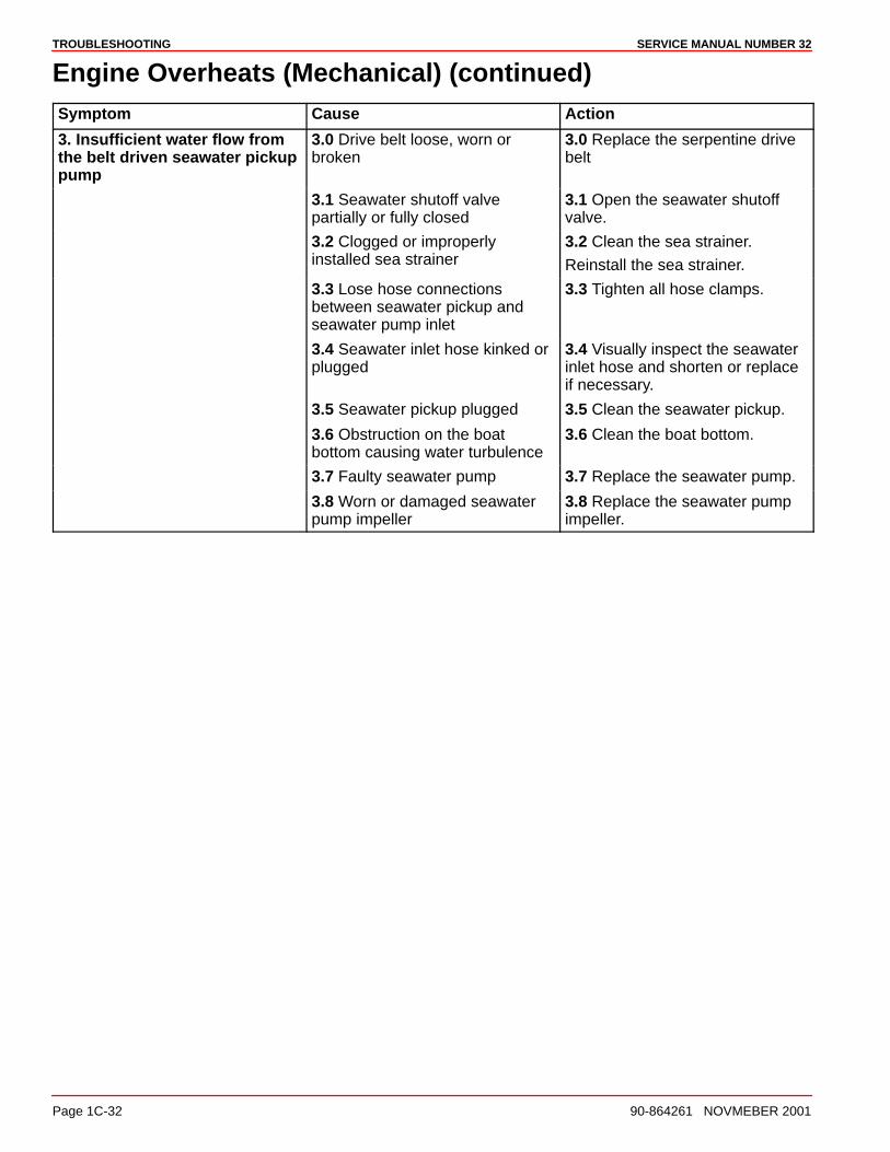
TROUBLESHOOTING SERVICE MANUAL NUMBER 32
Page 1C-32 90-864261 NOVMEBER 2001
Engine Overheats (Mechanical) (continued)Symptom Cause Action
3. Insufficient water flow fromthe belt driven seawater pickuppump
3.0 Drive belt loose, worn orbroken
3.0 Replace the serpentine drivebelt
3.1 Seawater shutoff valvepartially or fully closed
3.1 Open the seawater shutoffvalve.
3.2 Clogged or improperlyinstalled sea strainer
3.2 Clean the sea strainer.
Reinstall the sea strainer.
3.3 Lose hose connectionsbetween seawater pickup andseawater pump inlet
3.3 Tighten all hose clamps.
3.4 Seawater inlet hose kinked orplugged
3.4 Visually inspect the seawaterinlet hose and shorten or replaceif necessary.
3.5 Seawater pickup plugged 3.5 Clean the seawater pickup.
3.6 Obstruction on the boatbottom causing water turbulence
3.6 Clean the boat bottom.
3.7 Faulty seawater pump 3.7 Replace the seawater pump.
3.8 Worn or damaged seawaterpump impeller
3.8 Replace the seawater pumpimpeller.
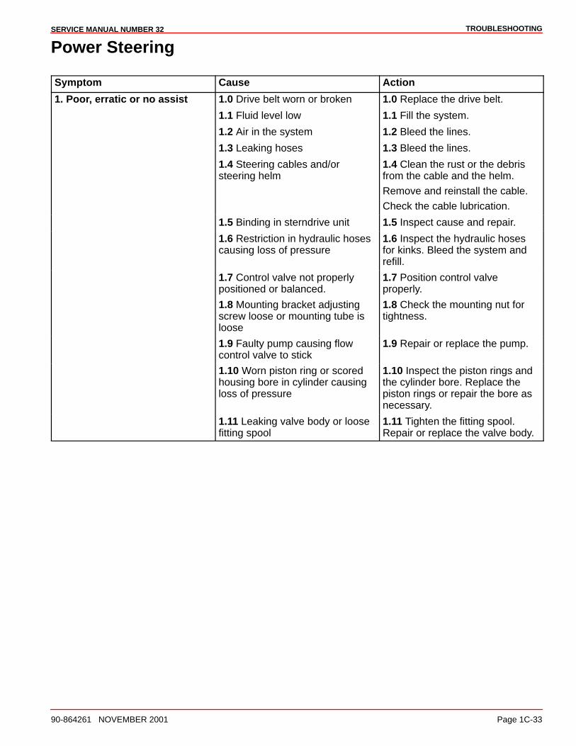
TROUBLESHOOTINGSERVICE MANUAL NUMBER 32
90-864261 NOVEMBER 2001 Page 1C-33
Power Steering
Symptom Cause Action
1. Poor, erratic or no assist 1.0 Drive belt worn or broken 1.0 Replace the drive belt.
1.1 Fluid level low 1.1 Fill the system.
1.2 Air in the system 1.2 Bleed the lines.
1.3 Leaking hoses 1.3 Bleed the lines.
1.4 Steering cables and/orsteering helm
1.4 Clean the rust or the debrisfrom the cable and the helm.
Remove and reinstall the cable.
Check the cable lubrication.
1.5 Binding in sterndrive unit 1.5 Inspect cause and repair.
1.6 Restriction in hydraulic hosescausing loss of pressure
1.6 Inspect the hydraulic hosesfor kinks. Bleed the system andrefill.
1.7 Control valve not properlypositioned or balanced.
1.7 Position control valveproperly.
1.8 Mounting bracket adjustingscrew loose or mounting tube isloose
1.8 Check the mounting nut fortightness.
1.9 Faulty pump causing flowcontrol valve to stick
1.9 Repair or replace the pump.
1.10 Worn piston ring or scoredhousing bore in cylinder causingloss of pressure
1.10 Inspect the piston rings andthe cylinder bore. Replace thepiston rings or repair the bore asnecessary.
1.11 Leaking valve body or loosefitting spool
1.11 Tighten the fitting spool.Repair or replace the valve body.
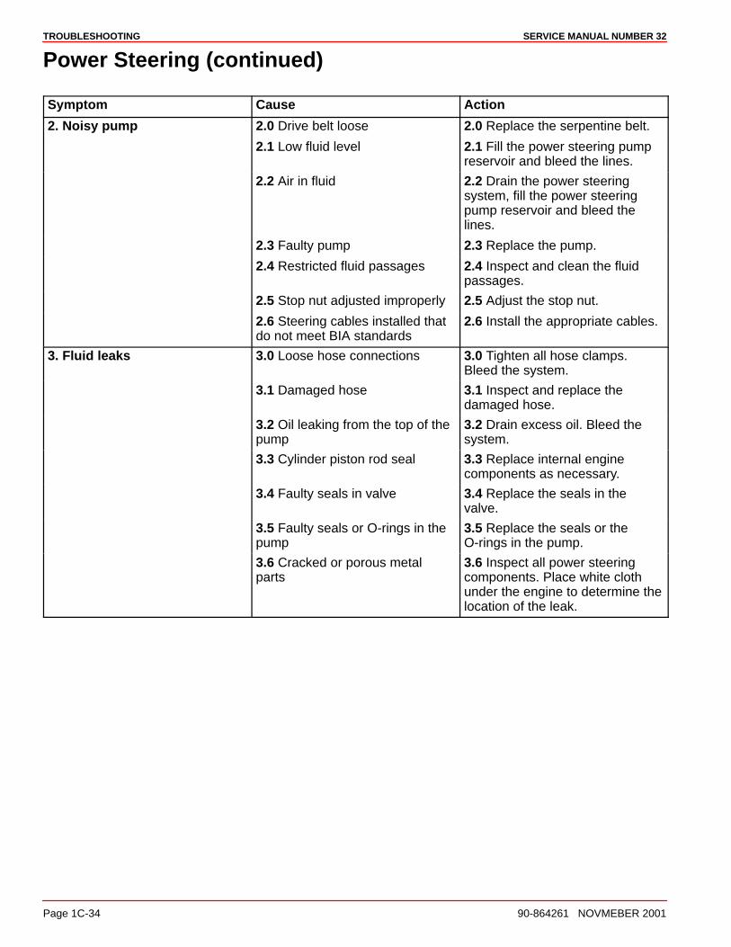
TROUBLESHOOTING SERVICE MANUAL NUMBER 32
Page 1C-34 90-864261 NOVMEBER 2001
Power Steering (continued)
Symptom Cause Action
2. Noisy pump 2.0 Drive belt loose 2.0 Replace the serpentine belt.
2.1 Low fluid level 2.1 Fill the power steering pumpreservoir and bleed the lines.
2.2 Air in fluid 2.2 Drain the power steeringsystem, fill the power steeringpump reservoir and bleed thelines.
2.3 Faulty pump 2.3 Replace the pump.
2.4 Restricted fluid passages 2.4 Inspect and clean the fluidpassages.
2.5 Stop nut adjusted improperly 2.5 Adjust the stop nut.
2.6 Steering cables installed thatdo not meet BIA standards
2.6 Install the appropriate cables.
3. Fluid leaks 3.0 Loose hose connections 3.0 Tighten all hose clamps.Bleed the system.
3.1 Damaged hose 3.1 Inspect and replace thedamaged hose.
3.2 Oil leaking from the top of thepump
3.2 Drain excess oil. Bleed thesystem.
3.3 Cylinder piston rod seal 3.3 Replace internal enginecomponents as necessary.
3.4 Faulty seals in valve 3.4 Replace the seals in thevalve.
3.5 Faulty seals or O-rings in thepump
3.5 Replace the seals or theO-rings in the pump.
3.6 Cracked or porous metalparts
3.6 Inspect all power steeringcomponents. Place white clothunder the engine to determine thelocation of the leak.

TROUBLESHOOTINGSERVICE MANUAL NUMBER 32
90-864261 NOVEMBER 2001 Page 1C-35
Drain System Will Not Drain Or Drains Slowly
Symptom Cause Action
1. Drain system will not drainor drains slowly
1.0 Drain system not open 1.0 Verify draining procedure.
1.1 Cooling system or drain holesplugged with debris
1.1 Inspect drain hole in the waterdistribution housing for debris.Remove the blue drain plugs andinspect for blockage.
Flush the cooling system anddrain the engine.
1.2 Air actuator malfunction 1.2 Inspect the air lines from theair manifold and the drainactuator for kinks, damage andleaks.
Inspect the air manifold and thefittings for cracks, leaks,damageor corrosion.
1.3 Boat sitting on an incline 1.3 Boat must be at rest and levelwhen draining the engine.
1.4 Draining the engine whileboat is in the water
1.4 Read Boat in the WaterProcedure in the Operation,Maintenance and WarrantyManual.
1.5 Water in the engine is frozen 1.5 Thaw engine and inspect forfreeze damage.
2. Drain system leaking at theorange drain seal
2.0 Drain rod misaligned 2.0 Realign the drain rod.
2.1 Drain rod bent 2.1 Replace the drain rod.
2.2 Drain rod not closedcompletely (red visible)
2.2 Close drain system.
2.3 Actuator piston not closed 2.3 Activate pressure relief valve.
Inspect and clean the waterdistribution housing and the seapump drain actuator. Replace ifdamaged.
3. Manual drain system leakingwhile underway
3.0 Drain rod misaligned 3.0 Realign the drain rod.
3.1 Drain rod bent 3.1 Replace the drain rod.
3.1 Drain rod scratched, cut ordamaged
3.1 Replace the drain rod.
3.2 Water distribution housingseal damaged
3.2 Replace the housing.
4. Water leaking out of thepressure relief valve on the airmanifold
4.0 Seawater pump seal leaking 4.0 Replace the drain portion ofthe seawater pump.
4.1 Vents on the drain actuatorare under the waterline
4.1 Empty water from bilge.

2A
MCM MODELSSERVICE MANUAL NUMBER 32
90-864261 NOVEMBER 2001 Page 2A-1
REMOVAL AND INSTALLATIONSection 2A - MCM Models
Table of Contents
Torque Specifications 2A-2. . . . . . . . . . . . . . . . Lubricants / Sealants / Adhesives 2A-3. . . . . Special Tools 2A-4. . . . . . . . . . . . . . . . . . . . . . . Removal 2A-5. . . . . . . . . . . . . . . . . . . . . . . . . . . Engine Installation 2A-8. . . . . . . . . . . . . . . . . . . Electrical Connections 2A-13. . . . . . . . . . . . . . .
EFI Electrical System Precautions 2A-13. . Installing Continuity Wire 2A-14. . . . . . . . . . Instrumentation Connections 2A-14. . . . . . . Trim Position Sender Connections 2A-15. . MerCathode Connections 2A-16. . . . . . . . . . Audio Warning Alarm Connections 2A-17. . Power Trim Pump Connections 2A-17. . . . .
Fluid Connections 2A-18. . . . . . . . . . . . . . . . . . . Fuel 2A-18. . . . . . . . . . . . . . . . . . . . . . . . . . . . Gear Lube Monitor Hose 2A-19. . . . . . . . . . Power Steering Hoses 2A-20. . . . . . . . . . . . Bravo Models and Alpha Seawater Cooled Models Using Sterndrive Water Pickups 2A-21. . . . Alpha or Bravo Models Using Alternative Water Pickups 2A-21. . . Coolant Recovery Bottle 2A-24. . . . . . . . . . .
Shift Cable Installation 2A-25. . . . . . . . . . . . . . . Alpha Models - Drive Unit Not Installed 2A-25. . . . . . . . . . . Bravo Models 2A-30. . . . . . . . . . . . . . . . . . . . Throttle Cable Installation and Adjustment 2A-35. . . . . . . . . . . . . . . . . . Battery Connection 2A-37. . . . . . . . . . . . . . . Engine Cover Installation 2A-37. . . . . . . . . .
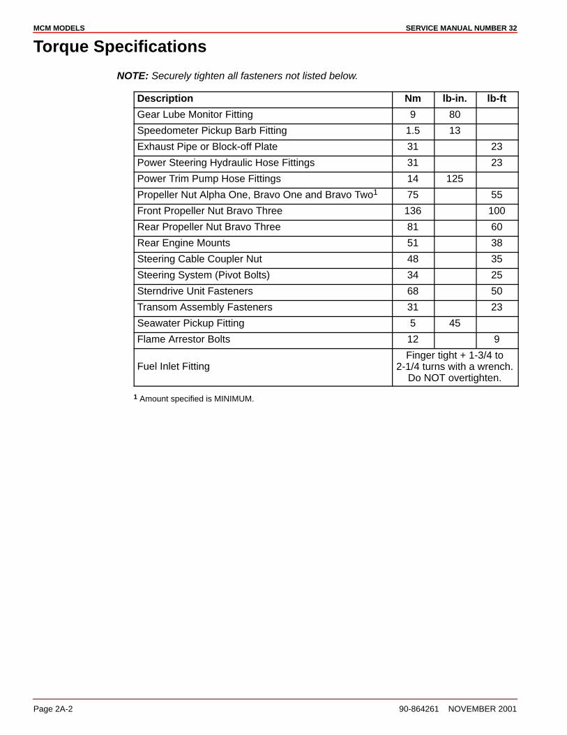
MCM MODELS SERVICE MANUAL NUMBER 32
Page 2A-2 90-864261 NOVEMBER 2001
Torque Specifications
NOTE: Securely tighten all fasteners not listed below.
Description Nm lb-in. lb-ft
Gear Lube Monitor Fitting 9 80
Speedometer Pickup Barb Fitting 1.5 13
Exhaust Pipe or Block-off Plate 31 23
Power Steering Hydraulic Hose Fittings 31 23
Power Trim Pump Hose Fittings 14 125
Propeller Nut Alpha One, Bravo One and Bravo Two1 75 55
Front Propeller Nut Bravo Three 136 100
Rear Propeller Nut Bravo Three 81 60
Rear Engine Mounts 51 38
Steering Cable Coupler Nut 48 35
Steering System (Pivot Bolts) 34 25
Sterndrive Unit Fasteners 68 50
Transom Assembly Fasteners 31 23
Seawater Pickup Fitting 5 45
Flame Arrestor Bolts 12 9
Fuel Inlet FittingFinger tight + 1-3/4 to
2-1/4 turns with a wrench.Do NOT overtighten.
1 Amount specified is MINIMUM.
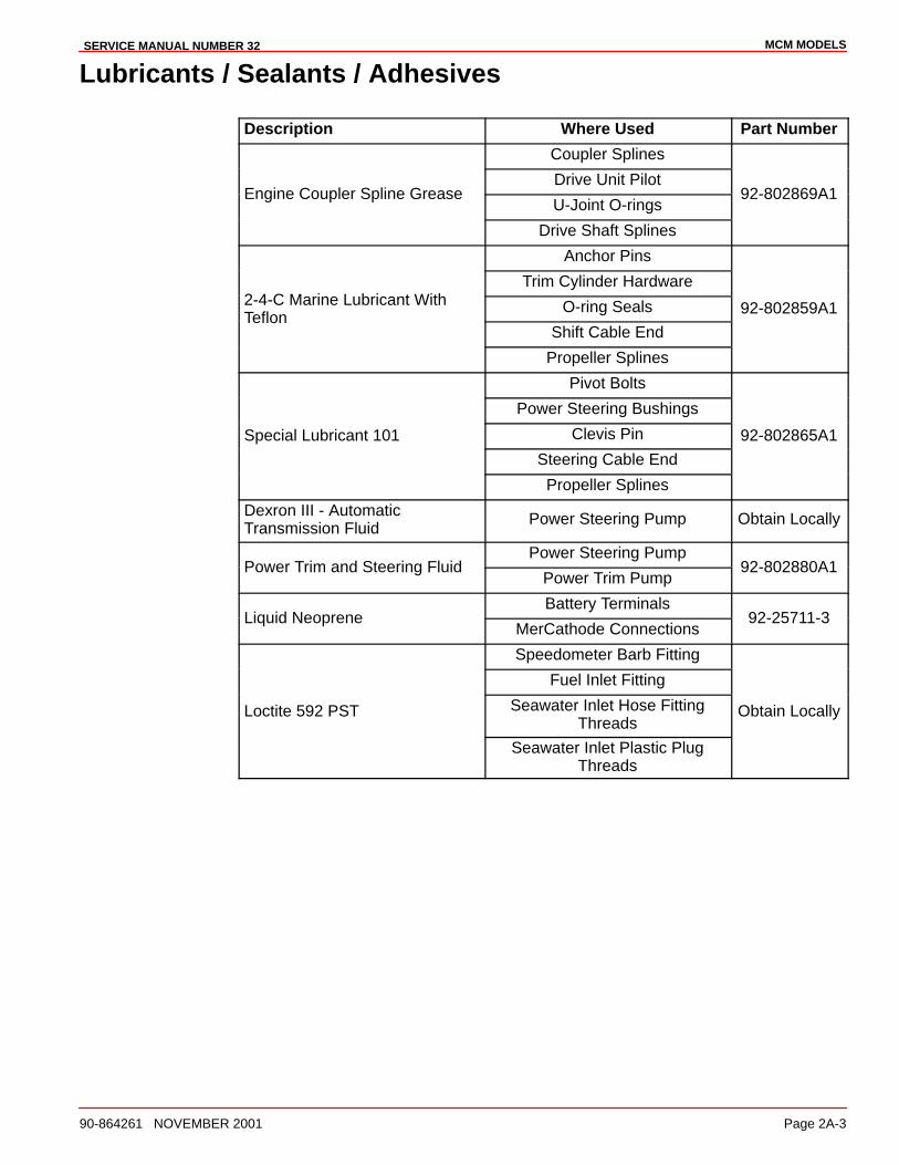
MCM MODELSSERVICE MANUAL NUMBER 32
90-864261 NOVEMBER 2001 Page 2A-3
Lubricants / Sealants / Adhesives
Description Where Used Part Number
Coupler Splines
Drive Unit PilotEngine Coupler Spline Grease
U-Joint O-rings92-802869A1
Drive Shaft Splines
Anchor Pins
Trim Cylinder Hardware2-4-C Marine Lubricant With O-ring Seals 92-802859A1Teflon
Shift Cable End
Propeller Splines
Pivot Bolts
Power Steering Bushings
Special Lubricant 101 Clevis Pin 92-802865A1
Steering Cable End
Propeller Splines
Dexron III - AutomaticTransmission Fluid
Power Steering Pump Obtain Locally
Power Steering PumpPower Trim and Steering Fluid
Power Trim Pump92-802880A1
Battery TerminalsLiquid Neoprene
MerCathode Connections92-25711-3
Speedometer Barb Fitting
Fuel Inlet Fitting
Loctite 592 PST Seawater Inlet Hose FittingThreads
Obtain Locally
Seawater Inlet Plastic PlugThreads

MCM MODELS SERVICE MANUAL NUMBER 32
Page 2A-4 90-864261 NOVEMBER 2001
Lubricants / Sealants / Adhesives (continued)
Description Where Used Part Number
Loctite 271 Seawater Inlet Nut 92-809819
Power Trim PumpEngine Oil
Shift Cable Pivot PointsObtain Locally
SAE 10W40 Engine Oil Power Trim Pump Obtain Locally
Marine Caulking Seawater Inlet MountingSurfaces
Obtain Locally
Power Tune Exhaust Tubes 92-802878-57
High Performance Gear Lube Sterndrive Unit 92-802854A1
Silicone Sealant Or Equivalent Screw Shaft Obtain Locally
Special Tools
Description Part Number
Transom Drilling Fixture 91-43693A2
Engine Alignment Tool 91-805475A1
Shift Cable Adjustment Tool 91-12427
Engine Mount Drilling Fixture 91-806794A1
Tapered Insert Tool 91-43579
Shift Shaft Slide Stabilizer Tool 91-809815A1
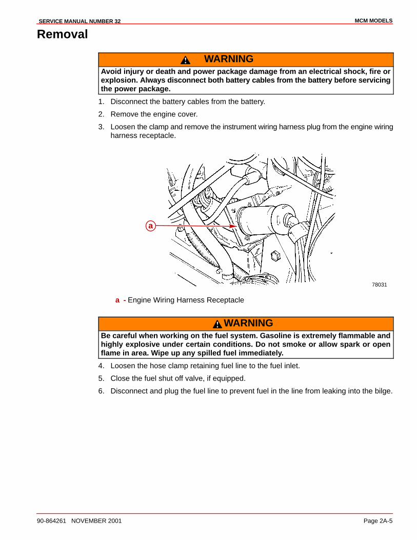
MCM MODELSSERVICE MANUAL NUMBER 32
90-864261 NOVEMBER 2001 Page 2A-5
Removal
WARNINGAvoid injury or death and power package damage from an electrical shock, fire orexplosion. Always disconnect both battery cables from the battery before servicingthe power package.
1. Disconnect the battery cables from the battery.
2. Remove the engine cover.
3. Loosen the clamp and remove the instrument wiring harness plug from the engine wiringharness receptacle.
78031
a
a - Engine Wiring Harness Receptacle
WARNINGBe careful when working on the fuel system. Gasoline is extremely flammable andhighly explosive under certain conditions. Do not smoke or allow spark or openflame in area. Wipe up any spilled fuel immediately.
4. Loosen the hose clamp retaining fuel line to the fuel inlet.
5. Close the fuel shut off valve, if equipped.
6. Disconnect and plug the fuel line to prevent fuel in the line from leaking into the bilge.
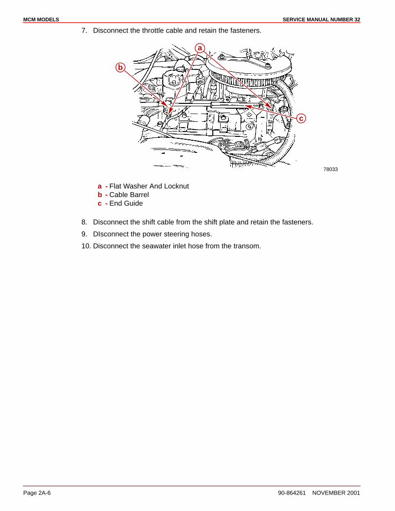
MCM MODELS SERVICE MANUAL NUMBER 32
Page 2A-6 90-864261 NOVEMBER 2001
7. Disconnect the throttle cable and retain the fasteners.
78033
a
c
b
a - Flat Washer And Locknutb - Cable Barrelc - End Guide
8. Disconnect the shift cable from the shift plate and retain the fasteners.
9. DIsconnect the power steering hoses.
10. Disconnect the seawater inlet hose from the transom.
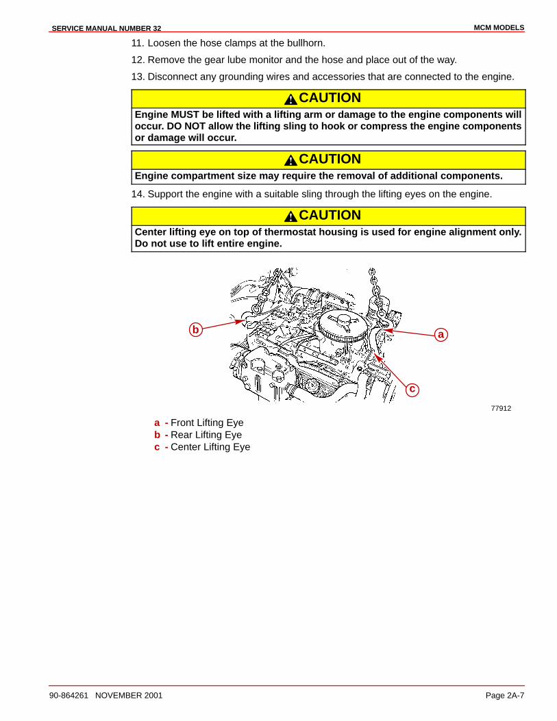
MCM MODELSSERVICE MANUAL NUMBER 32
90-864261 NOVEMBER 2001 Page 2A-7
11. Loosen the hose clamps at the bullhorn.
12. Remove the gear lube monitor and the hose and place out of the way.
13. Disconnect any grounding wires and accessories that are connected to the engine.
CAUTIONEngine MUST be lifted with a lifting arm or damage to the engine components willoccur. DO NOT allow the lifting sling to hook or compress the engine componentsor damage will occur.
CAUTIONEngine compartment size may require the removal of additional components.
14. Support the engine with a suitable sling through the lifting eyes on the engine.
CAUTIONCenter lifting eye on top of thermostat housing is used for engine alignment only.Do not use to lift entire engine.
77912
b a
c
a - Front Lifting Eyeb - Rear Lifting Eyec - Center Lifting Eye

MCM MODELS SERVICE MANUAL NUMBER 32
Page 2A-8 90-864261 NOVEMBER 2001
15. Remove the rear engine mounting bolts.
16. Remove the front lag bolts. Retain the fasteners.
72638
a
a
a - Lag Bolt (With Washers)
17. Carefully remove the engine.
Engine Installation
NOTE: An engine mount drilling fixture (91-806794A1) can be used to align and adjust theengine mounts. Refer to instructions the with the fixture for proper use.
1. Attach a suitable sling to the lifting eyes on the engine and adjust so that the engine islevel when suspended.
CAUTIONCenter lifting eye on top of the thermostat housing is used for engine alignmentonly. Do not use to lift the entire engine.
2. Lift the engine into position in the boat using an overhead hoist.
77912
b a
c
a - Front Lifting Eyeb - Rear Lifting Eyec - Center Lifting Eye
3. Ensure that the grounding stud and starter solenoid terminal are free of paint or anyother material that could cause a poor electrical connection.
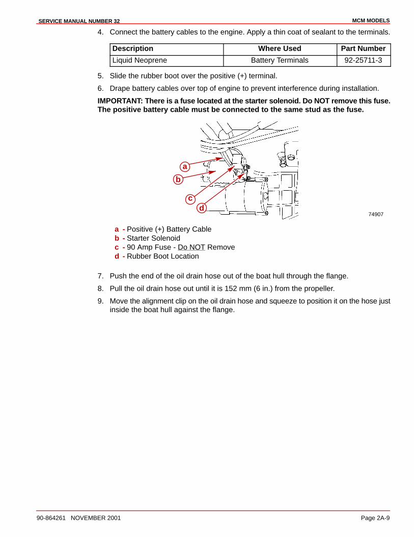
MCM MODELSSERVICE MANUAL NUMBER 32
90-864261 NOVEMBER 2001 Page 2A-9
4. Connect the battery cables to the engine. Apply a thin coat of sealant to the terminals.
Description Where Used Part Number
Liquid Neoprene Battery Terminals 92-25711-3
5. Slide the rubber boot over the positive (+) terminal.
6. Drape battery cables over top of engine to prevent interference during installation.
IMPORTANT: There is a fuse located at the starter solenoid. Do NOT remove this fuse.The positive battery cable must be connected to the same stud as the fuse.
74907
b
cd
a
a - Positive (+) Battery Cableb - Starter Solenoidc - 90 Amp Fuse - Do NOT Removed - Rubber Boot Location
7. Push the end of the oil drain hose out of the boat hull through the flange.
8. Pull the oil drain hose out until it is 152 mm (6 in.) from the propeller.
9. Move the alignment clip on the oil drain hose and squeeze to position it on the hose justinside the boat hull against the flange.
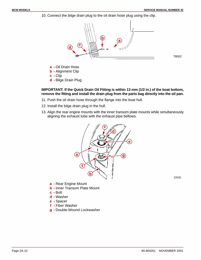
MCM MODELS SERVICE MANUAL NUMBER 32
Page 2A-10 90-864261 NOVEMBER 2001
10. Connect the bilge drain plug to the oil drain hose plug using the clip.
78002
ab
dc
a - Oil Drain Hoseb - Alignment Clipc - Clipd - Bilge Drain Plug
IMPORTANT: If the Quick Drain Oil Fitting is within 13 mm (1/2 in.) of the boat bottom,remove the fitting and install the drain plug from the parts bag directly into the oil pan.
11. Push the oil drain hose through the flange into the boat hull.
12. Install the bilge drain plug in the hull.
13. Align the rear engine mounts with the inner transom plate mounts while simultaneouslyaligning the exhaust tube with the exhaust pipe bellows.
22032b
f
a g
e
dc
a - Rear Engine Mountb - Inner Transom Plate Mountc - Boltd - Washere - Spacerf - Fiber Washerg - Double-Wound Lockwasher

MCM MODELSSERVICE MANUAL NUMBER 32
90-864261 NOVEMBER 2001 Page 2A-11
14. Install both the rear engine mounting bolts and the hardware. Torque the bolts and thehardware. Do not relieve the tension on the hoist.
50682
b
a
a - Exhaust Pipe Bellowsb - Exhaust Tube
Description Nm lb-in. lb-ft
Engine Mounting Bolts and Hardware 51 38
IMPORTANT: If the Quick Drain Oil Fitting is within 13 mm (1/2 in.) of the boat bottom,remove the fitting and install the drain plug from the parts bag directly into the oil pan.
15. Ensure that the quick drain oil fitting is more than 13 mm (1/2 in.) above the boat bottom.

MCM MODELS SERVICE MANUAL NUMBER 32
Page 2A-12 90-864261 NOVEMBER 2001
CAUTIONDo NOT use an alignment tool from a manufacturer other than Quicksilver as it maycause improper alignment and damage to the gimbal bearing or the engine coupler.
CAUTIONTo avoid damage to the gimbal bearing, the engine coupler or the alignment tool:
• Do NOT attempt to force the alignment tool!
• Do NOT raise or lower the engine with the alignment tool inserted (or partiallyinserted) in the gimbal bearing or the engine coupler.
16. Attempt to insert the solid end of the alignment tool through the gimbal bearing and intothe engine coupler splines.
17. If the tool does not fit, remove it and carefully raise or lower the front end of the engineusing the center alignment eye and attempt to insert the alignment tool.
18. Repeat Step 17. until the alignment tool installs easily (SLIDES FREELY WITH TWOFINGERS) all the way into and out of the engine coupler splines. Do not check byturning.
22029
b
a
a - Alignment Tool (Use Only Recommended Alignment Tool)b - Insert This End Of Alignment Tool Through Gimbal Housing Assembly
27647
c
b
a
a - Alignment Toolb - Gimbal Bearingc - Engine Coupler
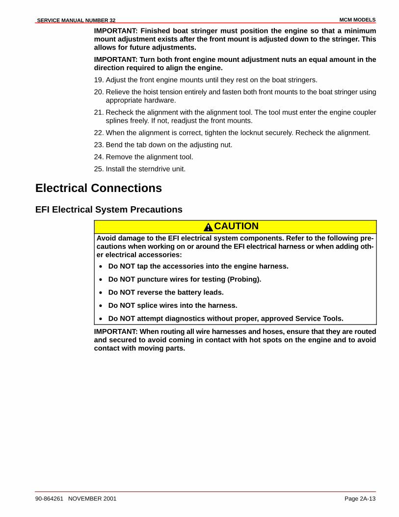
MCM MODELSSERVICE MANUAL NUMBER 32
90-864261 NOVEMBER 2001 Page 2A-13
IMPORTANT: Finished boat stringer must position the engine so that a minimummount adjustment exists after the front mount is adjusted down to the stringer. Thisallows for future adjustments.
IMPORTANT: Turn both front engine mount adjustment nuts an equal amount in thedirection required to align the engine.
19. Adjust the front engine mounts until they rest on the boat stringers.
20. Relieve the hoist tension entirely and fasten both front mounts to the boat stringer usingappropriate hardware.
21. Recheck the alignment with the alignment tool. The tool must enter the engine couplersplines freely. If not, readjust the front mounts.
22. When the alignment is correct, tighten the locknut securely. Recheck the alignment.
23. Bend the tab down on the adjusting nut.
24. Remove the alignment tool.
25. Install the sterndrive unit.
Electrical Connections
EFI Electrical System Precautions
CAUTIONAvoid damage to the EFI electrical system components. Refer to the following pre-cautions when working on or around the EFI electrical harness or when adding oth-er electrical accessories:
• Do NOT tap the accessories into the engine harness.
• Do NOT puncture wires for testing (Probing).
• Do NOT reverse the battery leads.
• Do NOT splice wires into the harness.
• Do NOT attempt diagnostics without proper, approved Service Tools.
IMPORTANT: When routing all wire harnesses and hoses, ensure that they are routedand secured to avoid coming in contact with hot spots on the engine and to avoidcontact with moving parts.
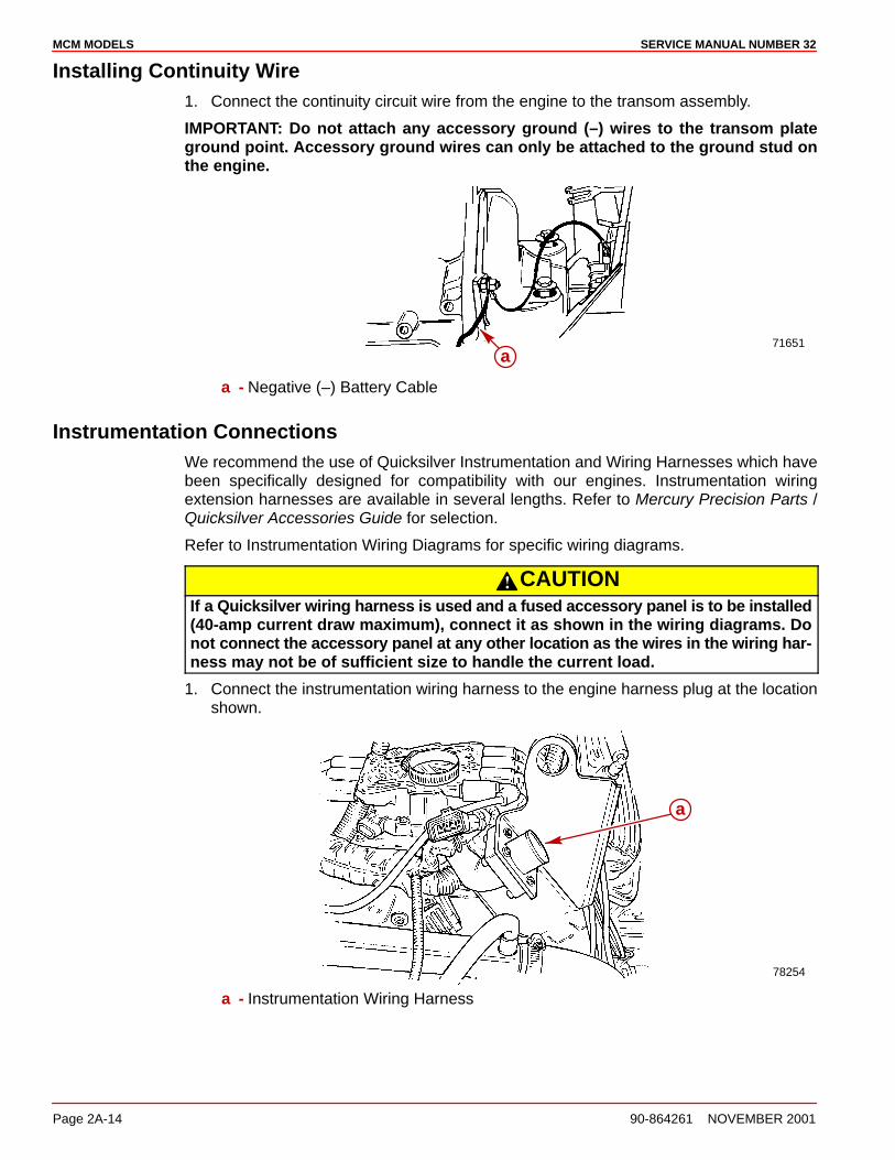
MCM MODELS SERVICE MANUAL NUMBER 32
Page 2A-14 90-864261 NOVEMBER 2001
Installing Continuity Wire1. Connect the continuity circuit wire from the engine to the transom assembly.
IMPORTANT: Do not attach any accessory ground (–) wires to the transom plateground point. Accessory ground wires can only be attached to the ground stud onthe engine.
71651a
a - Negative (–) Battery Cable
Instrumentation ConnectionsWe recommend the use of Quicksilver Instrumentation and Wiring Harnesses which havebeen specifically designed for compatibility with our engines. Instrumentation wiringextension harnesses are available in several lengths. Refer to Mercury Precision Parts /Quicksilver Accessories Guide for selection.
Refer to Instrumentation Wiring Diagrams for specific wiring diagrams.
CAUTIONIf a Quicksilver wiring harness is used and a fused accessory panel is to be installed(40-amp current draw maximum), connect it as shown in the wiring diagrams. Donot connect the accessory panel at any other location as the wires in the wiring har-ness may not be of sufficient size to handle the current load.
1. Connect the instrumentation wiring harness to the engine harness plug at the locationshown.
78254
a
a - Instrumentation Wiring Harness

MCM MODELSSERVICE MANUAL NUMBER 32
90-864261 NOVEMBER 2001 Page 2A-15
2. Place the hose clamp on the location shown.
78031
a
a - Hose Clamp Location
Trim Position Sender Connections1. Connect the trim position sender wires from the transom assembly to the engine
harness. Use the ORG/GRY wire for analog gauges and the ORG/WHT for digitalgauges.
BLK
ORG/WHT BLK
BLK
74029
a b
a - Engine Harness Bullet Connectorb - Transom Assembly Bullet Connectors

MCM MODELS SERVICE MANUAL NUMBER 32
Page 2A-16 90-864261 NOVEMBER 2001
MerCathode ConnectionsThe MerCathode controller assembly is located on the back of the front lifting eye. The upperhose must be disconnected from the thermostat housing for access.
1. Move or remove the thermostat housing hose to gain access to the MerCathodecontroller assembly.
78129
ab
check
a - MerCathode Controller Locationb - Thermostat Housing Hose
2. Connect the wires to the MerCathode controller assembly as shown. Apply a thin coatof sealant to all wire connections.
IMPORTANT: The opposite end of the red/purple wire must be connected directly tothe battery positive (+) terminal. Do NOT connect it to a switched positive (+) circuit.The MerCathode system must function continuously for proper corrosionprotection.
22232a b c d
a - ORANGE Wire - From Electrode on Transom Assemblyb - RED/PURPLE Wire - Connect (Other End) To Positive (+) Battery Terminalc - BLACK Wire - From Engine Harnessd - BROWN Wire - From Electrode on Transom Assembly
Description Where Used Part Number
Liquid Neoprene MerCathode Connections 92-25711-3

MCM MODELSSERVICE MANUAL NUMBER 32
90-864261 NOVEMBER 2001 Page 2A-17
Audio Warning Alarm Connections1. Connect the PURPLE wire from the alarm to any PURPLE wire terminal on the
instrument gauge or the ignition switch. Tighten the connection securely.
2. Connect the TAN/BLUE wire from the alarm to the TAN/ BLUE wire from the instrumentharness.
Power Trim Pump ConnectionsIMPORTANT: Make the hydraulic connections as quickly as possible to prevent oilfrom leaking out of the system. Be careful not to cross-thread or overtighten the hosefittings.
1. Connect the hydraulic hoses to the trim pump. Torque the fittings.
Description Nm lb-in. lb-ft
Hydraulic Hose Fittings 14 125
2. Connect the power trim pump control harness to the trim pump.
3. Connect the trim limit switch wires and secure with the wire retainer and tie strap.
75126
50630
75127
50632
a
c
e
fg
b
d
a - Black Hose Fitting (UP Circuit)b - Gray Hose Fitting (DOWN Circuit)c - Control Harnessd - Tie Strape - Trim Limit Switch Wire (With Blue Sleeve) To BLUE/WHITE Harness Wiref - Trim Limit Switch Wire (With Purple Sleeve) To PURPLE/WHITE Harness Wireg - Wire Retainer And Tie Strap
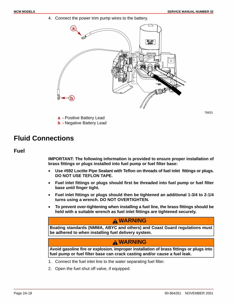
MCM MODELS SERVICE MANUAL NUMBER 32
Page 2A-18 90-864261 NOVEMBER 2001
4. Connect the power trim pump wires to the battery.
76631
a
b
a - Positive Battery Leadb - Negative Battery Lead
Fluid Connections
FuelIMPORTANT: The following information is provided to ensure proper installation ofbrass fittings or plugs installed into fuel pump or fuel filter base:
• Use #592 Loctite Pipe Sealant with Teflon on threads of fuel inlet fittings or plugs.DO NOT USE TEFLON TAPE.
• Fuel inlet fittings or plugs should first be threaded into fuel pump or fuel filterbase until finger tight.
• Fuel inlet fittings or plugs should then be tightened an additional 1-3/4 to 2-1/4turns using a wrench. DO NOT OVERTIGHTEN.
• To prevent over-tightening when installing a fuel line, the brass fittings should beheld with a suitable wrench as fuel inlet fittings are tightened securely.
WARNINGBoating standards (NMMA, ABYC and others) and Coast Guard regulations mustbe adhered to when installing fuel delivery system.
WARNINGAvoid gasoline fire or explosion. Improper installation of brass fittings or plugs intofuel pump or fuel filter base can crack casting and/or cause a fuel leak.
1. Connect the fuel inlet line to the water separating fuel filter.
2. Open the fuel shut off valve, if equipped.
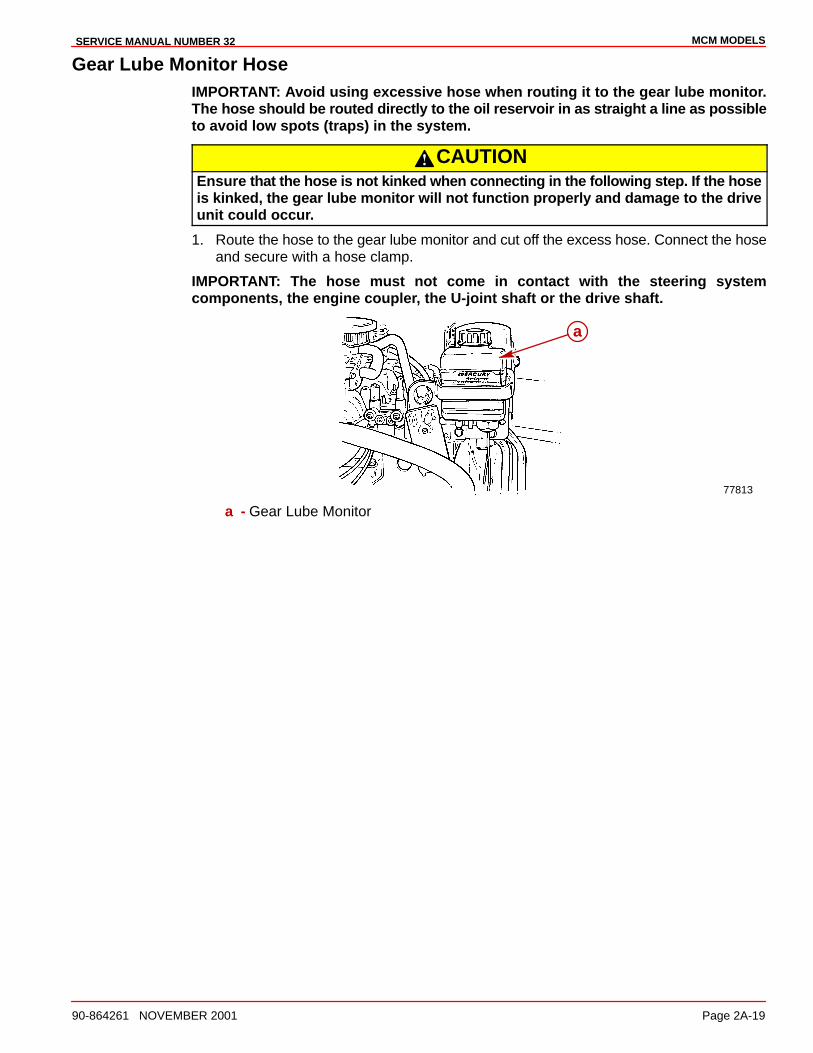
MCM MODELSSERVICE MANUAL NUMBER 32
90-864261 NOVEMBER 2001 Page 2A-19
Gear Lube Monitor HoseIMPORTANT: Avoid using excessive hose when routing it to the gear lube monitor.The hose should be routed directly to the oil reservoir in as straight a line as possibleto avoid low spots (traps) in the system.
CAUTIONEnsure that the hose is not kinked when connecting in the following step. If the hoseis kinked, the gear lube monitor will not function properly and damage to the driveunit could occur.
1. Route the hose to the gear lube monitor and cut off the excess hose. Connect the hoseand secure with a hose clamp.
IMPORTANT: The hose must not come in contact with the steering systemcomponents, the engine coupler, the U-joint shaft or the drive shaft.
77813
a
a - Gear Lube Monitor
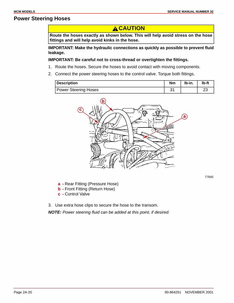
MCM MODELS SERVICE MANUAL NUMBER 32
Page 2A-20 90-864261 NOVEMBER 2001
Power Steering Hoses
CAUTIONRoute the hoses exactly as shown below. This will help avoid stress on the hosefittings and will help avoid kinks in the hose.
IMPORTANT: Make the hydraulic connections as quickly as possible to prevent fluidleakage.
IMPORTANT: Be careful not to cross-thread or overtighten the fittings.
1. Route the hoses. Secure the hoses to avoid contact with moving components.
2. Connect the power steering hoses to the control valve. Torque both fittings.
Description Nm lb-in. lb-ft
Power Steering Hoses 31 23
77845
b
a
c
a - Rear Fitting (Pressure Hose)b - Front Fitting (Return Hose)c - Control Valve
3. Use extra hose clips to secure the hose to the transom.
NOTE: Power steering fluid can be added at this point, if desired.
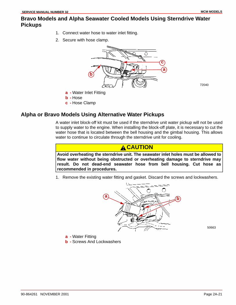
MCM MODELSSERVICE MANUAL NUMBER 32
90-864261 NOVEMBER 2001 Page 2A-21
Bravo Models and Alpha Seawater Cooled Models Using Sterndrive WaterPickups
1. Connect water hose to water inlet fitting.
2. Secure with hose clamp.
72040
ba
c
a - Water Inlet Fittingb - Hosec - Hose Clamp
Alpha or Bravo Models Using Alternative Water PickupsA water inlet block-off kit must be used if the sterndrive unit water pickup will not be usedto supply water to the engine. When installing the block-off plate, it is necessary to cut thewater hose that is located between the bell housing and the gimbal housing. This allowswater to continue to circulate through the sterndrive unit for cooling.
CAUTIONAvoid overheating the sterndrive unit. The seawater inlet holes must be allowed toflow water without being obstructed or overheating damage to sterndrive mayresult. Do not dead-end seawater hose from bell housing. Cut hose asrecommended in procedures.
1. Remove the existing water fitting and gasket. Discard the screws and lockwashers.
50663
a b
a - Water Fittingb - Screws And Lockwashers
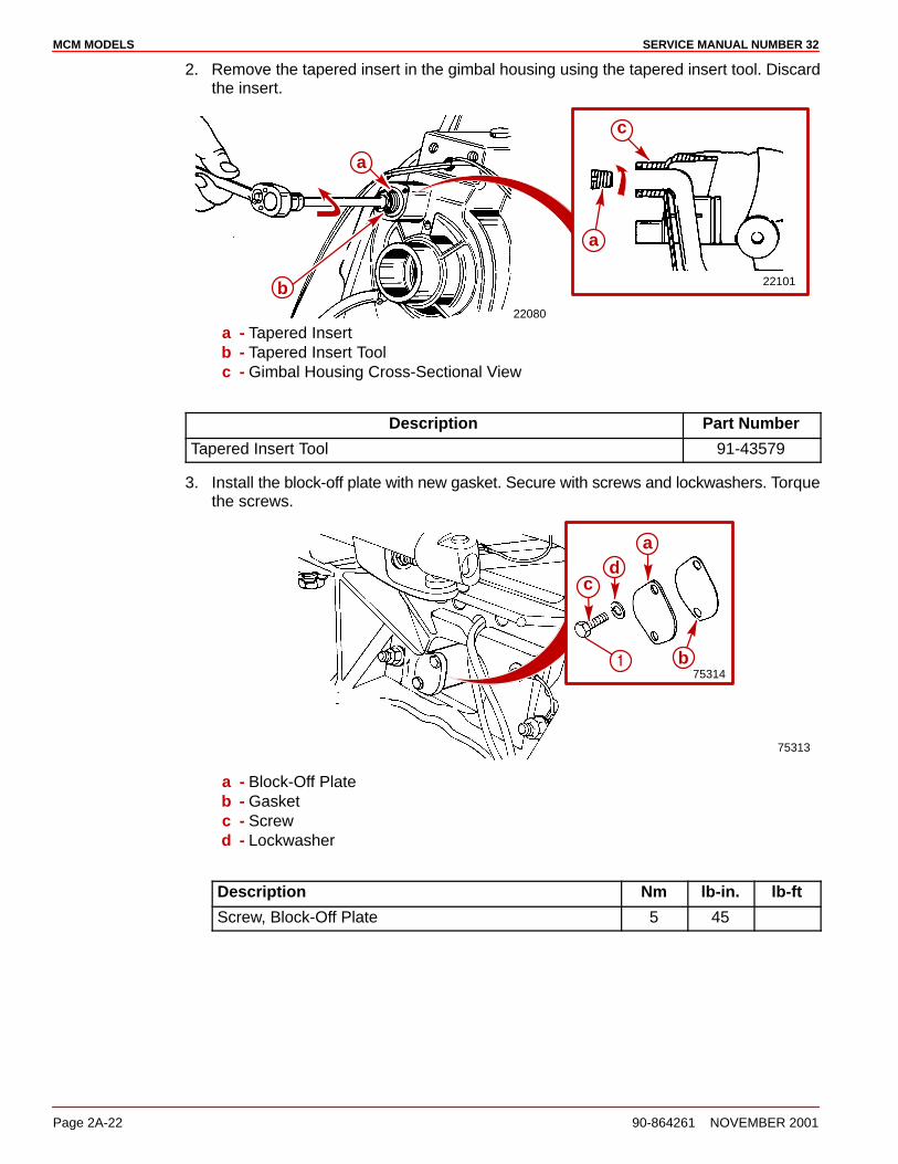
MCM MODELS SERVICE MANUAL NUMBER 32
Page 2A-22 90-864261 NOVEMBER 2001
2. Remove the tapered insert in the gimbal housing using the tapered insert tool. Discardthe insert.
22080
a
b 22101
a
c
a - Tapered Insertb - Tapered Insert Toolc - Gimbal Housing Cross-Sectional View
Description Part Number
Tapered Insert Tool 91-43579
3. Install the block-off plate with new gasket. Secure with screws and lockwashers. Torquethe screws.
75313
75314
a
b
cd
�
a - Block-Off Plateb - Gasketc - Screwd - Lockwasher
Description Nm lb-in. lb-ft
Screw, Block-Off Plate 5 45

MCM MODELSSERVICE MANUAL NUMBER 32
90-864261 NOVEMBER 2001 Page 2A-23
4. Move the trim limit switch wires and speedometer hose aside. Reach between thegimbal housing and the bell housing and detach the water hose from the gimbal housingwhere the tapered insert was removed in Step 2.
22101
c
71184
a
b
d
e
a - Trim Limit Switch Wiresb - Speedometer Hosec - Gimbal Housingd - Water Hosee - Tapered Insert
WARNINGAvoid water leakage into boat. Damage to U-joint bellows could result in waterentering the boat. Do not damage the U-joint bellows when removing a section ofthe water hose attached between the gimbal housing and bell housing.
NOTE: Move the trim limit switch wires and speedometer hose to avoid damaging themwhen cutting the water hose. The existing tie strap and clip can be reused if they are movedand repositioned after the hose is cut.
5. Cut completely through the water hose 127 mm (5 in.) in front of the aft end of the hosewhere it is fitted into the bell housing. in the area shown. Do NOT damage the U-jointbellows. Discard loose hose piece.
6. Secure the trim limit switch wires and speedometer hose to the remaining section ofwater hose using existing tie strap and clip.
71184
b
c
f
a
e
d
b
c
f
a
e
d
a - Tie Strapb - Clipc - Water Inlet Hosed - Speedometer Hosee - Trim Limit Wire Harnessf - Cutting Area

MCM MODELS SERVICE MANUAL NUMBER 32
Page 2A-24 90-864261 NOVEMBER 2001
Coolant Recovery Bottle
CAUTIONAvoid engine overheating and subsequent damage to the engine. The coolantrecovery system will not operate properly without proper sealing. The plastictubing MUST seal completely at the connections.
1. Connect the plastic tubing to the bayonet fitting on the heat exchanger. Secure with thetubing clamp provided.
70548a
b
a - Plastic Tubingb - Tubing Clamp
2. Remove the cap from the coolant recovery reservoir and fill to the FULL mark withcoolant solution. Reinstall the cap.
3. Recheck the coolant level after the first open-throttle boat test and add coolant, ifnecessary.
4. Maintain the coolant level in the coolant recovery reservoir between the ADD and FULLmarks with the engine at normal operating temperature.
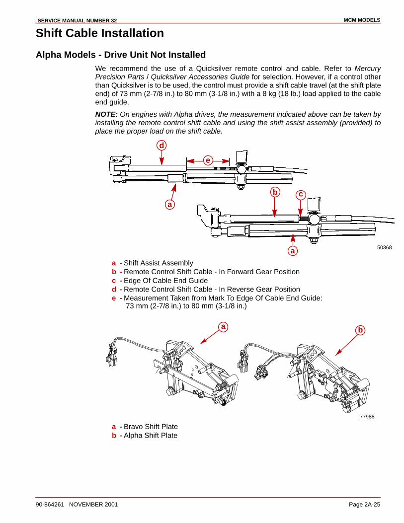
MCM MODELSSERVICE MANUAL NUMBER 32
90-864261 NOVEMBER 2001 Page 2A-25
Shift Cable Installation
Alpha Models - Drive Unit Not InstalledWe recommend the use of a Quicksilver remote control and cable. Refer to MercuryPrecision Parts / Quicksilver Accessories Guide for selection. However, if a control otherthan Quicksilver is to be used, the control must provide a shift cable travel (at the shift plateend) of 73 mm (2-7/8 in.) to 80 mm (3-1/8 in.) with a 8 kg (18 lb.) load applied to the cableend guide.
NOTE: On engines with Alpha drives, the measurement indicated above can be taken byinstalling the remote control shift cable and using the shift assist assembly (provided) toplace the proper load on the shift cable.
50368
a
a
b c
a
d
e
a - Shift Assist Assemblyb - Remote Control Shift Cable - In Forward Gear Positionc - Edge Of Cable End Guided - Remote Control Shift Cable - In Reverse Gear Positione - Measurement Taken from Mark To Edge Of Cable End Guide:
73 mm (2-7/8 in.) to 80 mm (3-1/8 in.)
77988
a
ba
a - Bravo Shift Plateb - Alpha Shift Plate
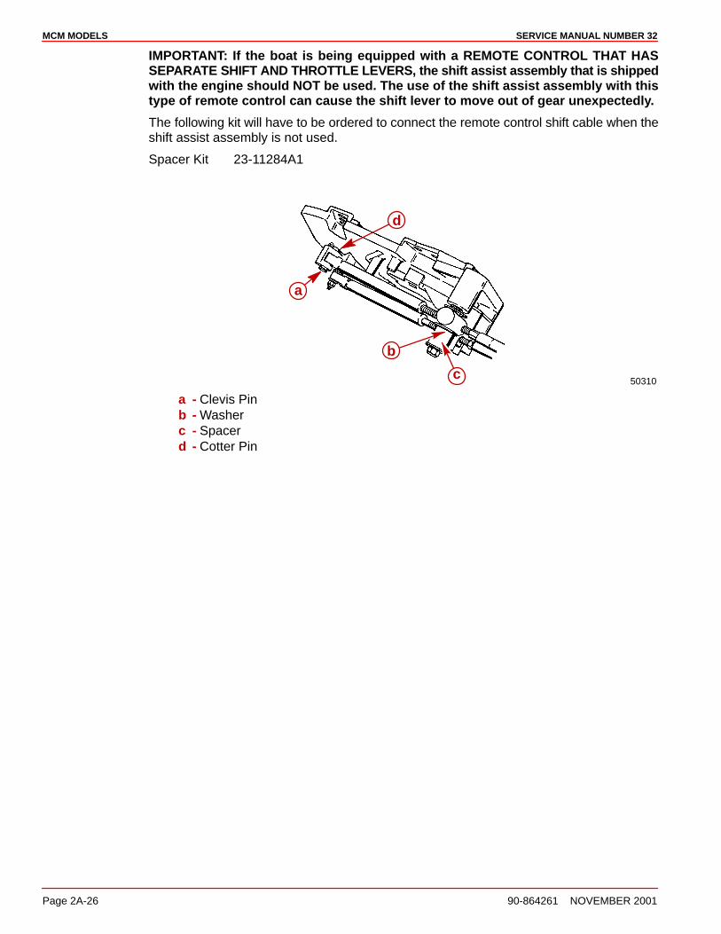
MCM MODELS SERVICE MANUAL NUMBER 32
Page 2A-26 90-864261 NOVEMBER 2001
IMPORTANT: If the boat is being equipped with a REMOTE CONTROL THAT HASSEPARATE SHIFT AND THROTTLE LEVERS, the shift assist assembly that is shippedwith the engine should NOT be used. The use of the shift assist assembly with thistype of remote control can cause the shift lever to move out of gear unexpectedly.
The following kit will have to be ordered to connect the remote control shift cable when theshift assist assembly is not used.
Spacer Kit 23-11284A1
50310
a
d
b
c
a - Clevis Pinb - Washerc - Spacerd - Cotter Pin
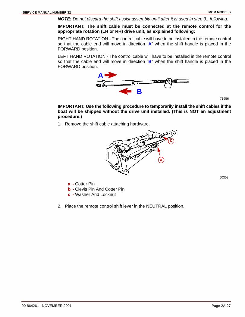
MCM MODELSSERVICE MANUAL NUMBER 32
90-864261 NOVEMBER 2001 Page 2A-27
NOTE: Do not discard the shift assist assembly until after it is used in step 3., following.
IMPORTANT: The shift cable must be connected at the remote control for theappropriate rotation (LH or RH) drive unit, as explained following:
RIGHT HAND ROTATION - The control cable will have to be installed in the remote controlso that the cable end will move in direction “A” when the shift handle is placed in theFORWARD position.
LEFT HAND ROTATION - The control cable will have to be installed in the remote controlso that the cable end will move in direction “B” when the shift handle is placed in theFORWARD position.
71656
A
B
IMPORTANT: Use the following procedure to temporarily install the shift cables if theboat will be shipped without the drive unit installed. (This is NOT an adjustmentprocedure.)
1. Remove the shift cable attaching hardware.
50308
b
a
c
a - Cotter Pinb - Clevis Pin And Cotter Pinc - Washer And Locknut
2. Place the remote control shift lever in the NEUTRAL position.
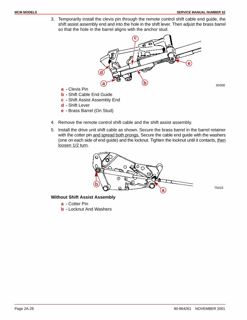
MCM MODELS SERVICE MANUAL NUMBER 32
Page 2A-28 90-864261 NOVEMBER 2001
3. Temporarily install the clevis pin through the remote control shift cable end guide, theshift assist assembly end and into the hole in the shift lever. Then adjust the brass barrelso that the hole in the barrel aligns with the anchor stud.
50308
e
d
a
c
ba - Clevis Pinb - Shift Cable End Guidec - Shift Assist Assembly Endd - Shift Levere - Brass Barrel (On Stud)
4. Remove the remote control shift cable and the shift assist assembly.
5. Install the drive unit shift cable as shown. Secure the brass barrel in the barrel retainerwith the cotter pin and spread both prongs. Secure the cable end guide with the washers(one on each side of end guide) and the locknut. Tighten the locknut until it contacts, thenloosen 1/2 turn.
75415ab
Without Shift Assist Assemblya - Cotter Pinb - Locknut And Washers
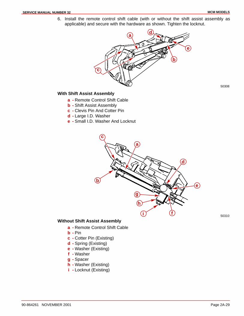
MCM MODELSSERVICE MANUAL NUMBER 32
90-864261 NOVEMBER 2001 Page 2A-29
6. Install the remote control shift cable (with or without the shift assist assembly asapplicable) and secure with the hardware as shown. Tighten the locknut.
50308
c
a
b
e
d
With Shift Assist Assemblya - Remote Control Shift Cableb - Shift Assist Assemblyc - Clevis Pin And Cotter Pind - Large I.D. Washere - Small I.D. Washer And Locknut
50310
c
b
a
g
h
i f
d
e
Without Shift Assist Assemblya - Remote Control Shift Cableb - Pinc - Cotter Pin (Existing)d - Spring (Existing)e - Washer (Existing)f - Washerg - Spacerh - Washer (Existing)i - Locknut (Existing)
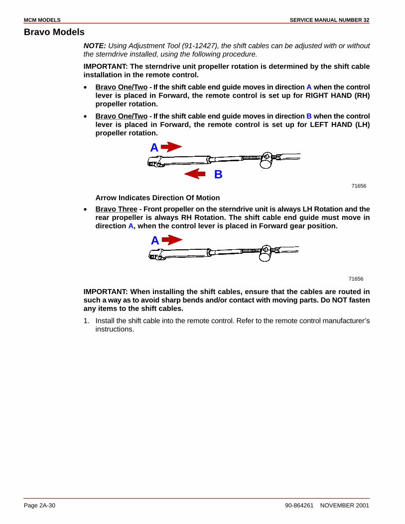
MCM MODELS SERVICE MANUAL NUMBER 32
Page 2A-30 90-864261 NOVEMBER 2001
Bravo ModelsNOTE: Using Adjustment Tool (91-12427), the shift cables can be adjusted with or withoutthe sterndrive installed, using the following procedure.
IMPORTANT: The sterndrive unit propeller rotation is determined by the shift cableinstallation in the remote control.
• Bravo One/Two - If the shift cable end guide moves in direction A when the controllever is placed in Forward, the remote control is set up for RIGHT HAND (RH)propeller rotation.
• Bravo One/Two - If the shift cable end guide moves in direction B when the controllever is placed in Forward, the remote control is set up for LEFT HAND (LH)propeller rotation.
71656
A
B
Arrow Indicates Direction Of Motion
• Bravo Three - Front propeller on the sterndrive unit is always LH Rotation and therear propeller is always RH Rotation. The shift cable end guide must move indirection A, when the control lever is placed in Forward gear position.
71656
A
IMPORTANT: When installing the shift cables, ensure that the cables are routed insuch a way as to avoid sharp bends and/or contact with moving parts. Do NOT fastenany items to the shift cables.
1. Install the shift cable into the remote control. Refer to the remote control manufacturer’sinstructions.
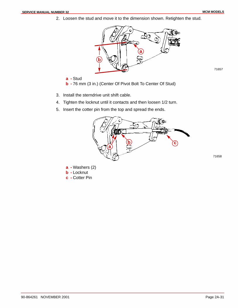
MCM MODELSSERVICE MANUAL NUMBER 32
90-864261 NOVEMBER 2001 Page 2A-31
2. Loosen the stud and move it to the dimension shown. Retighten the stud.
71657
a
b
a - Studb - 76 mm (3 in.) (Center Of Pivot Bolt To Center Of Stud)
3. Install the sterndrive unit shift cable.
4. Tighten the locknut until it contacts and then loosen 1/2 turn.
5. Insert the cotter pin from the top and spread the ends.
71658
cba
a - Washers (2)b - Locknutc - Cotter Pin
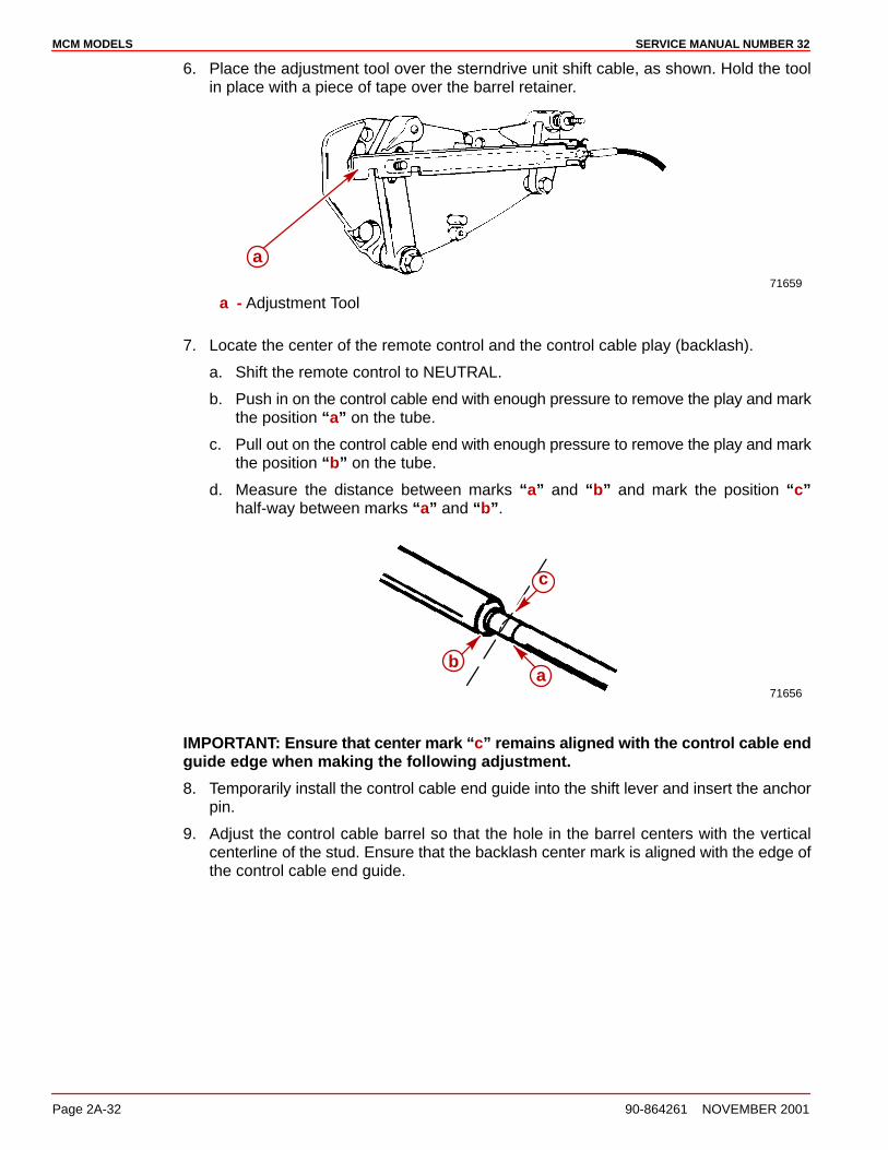
MCM MODELS SERVICE MANUAL NUMBER 32
Page 2A-32 90-864261 NOVEMBER 2001
6. Place the adjustment tool over the sterndrive unit shift cable, as shown. Hold the toolin place with a piece of tape over the barrel retainer.
71659
a
a - Adjustment Tool
7. Locate the center of the remote control and the control cable play (backlash).
a. Shift the remote control to NEUTRAL.
b. Push in on the control cable end with enough pressure to remove the play and markthe position “a” on the tube.
c. Pull out on the control cable end with enough pressure to remove the play and markthe position “b” on the tube.
d. Measure the distance between marks “a” and “b” and mark the position “c”half-way between marks “a” and “b”.
71656
c
ab
IMPORTANT: Ensure that center mark “c” remains aligned with the control cable endguide edge when making the following adjustment.
8. Temporarily install the control cable end guide into the shift lever and insert the anchorpin.
9. Adjust the control cable barrel so that the hole in the barrel centers with the verticalcenterline of the stud. Ensure that the backlash center mark is aligned with the edge ofthe control cable end guide.
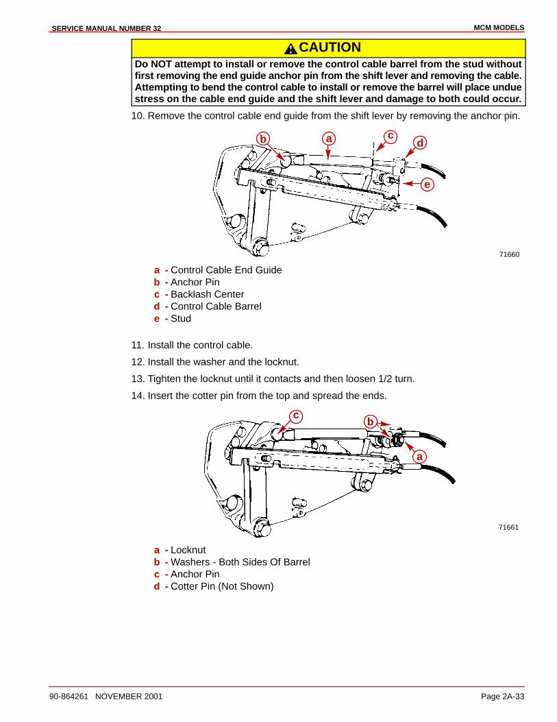
MCM MODELSSERVICE MANUAL NUMBER 32
90-864261 NOVEMBER 2001 Page 2A-33
CAUTIONDo NOT attempt to install or remove the control cable barrel from the stud withoutfirst removing the end guide anchor pin from the shift lever and removing the cable.Attempting to bend the control cable to install or remove the barrel will place unduestress on the cable end guide and the shift lever and damage to both could occur.
10. Remove the control cable end guide from the shift lever by removing the anchor pin.
71660
ab cd
e
a - Control Cable End Guideb - Anchor Pinc - Backlash Centerd - Control Cable Barrele - Stud
11. Install the control cable.
12. Install the washer and the locknut.
13. Tighten the locknut until it contacts and then loosen 1/2 turn.
14. Insert the cotter pin from the top and spread the ends.
71661
b
a
c
a - Locknutb - Washers - Both Sides Of Barrelc - Anchor Pind - Cotter Pin (Not Shown)
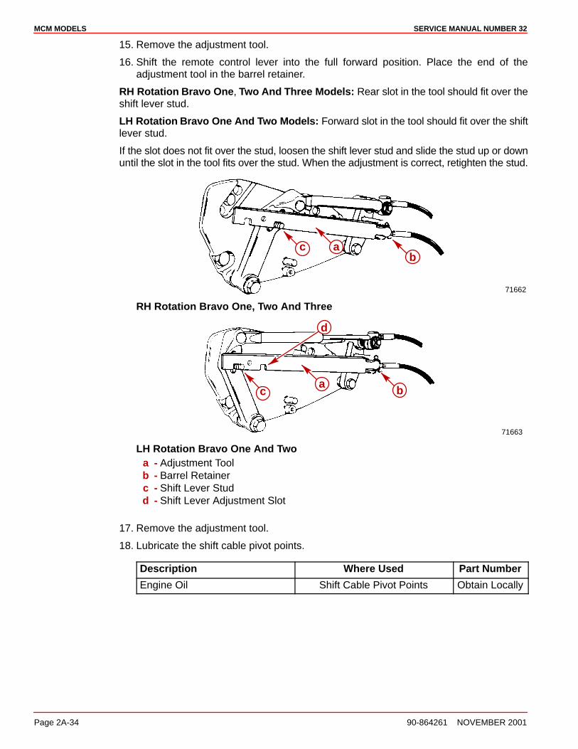
MCM MODELS SERVICE MANUAL NUMBER 32
Page 2A-34 90-864261 NOVEMBER 2001
15. Remove the adjustment tool.
16. Shift the remote control lever into the full forward position. Place the end of theadjustment tool in the barrel retainer.
RH Rotation Bravo One, Two And Three Models: Rear slot in the tool should fit over theshift lever stud.
LH Rotation Bravo One And Two Models: Forward slot in the tool should fit over the shiftlever stud.
If the slot does not fit over the stud, loosen the shift lever stud and slide the stud up or downuntil the slot in the tool fits over the stud. When the adjustment is correct, retighten the stud.
71662
ab
c
RH Rotation Bravo One, Two And Three
71663
a bc
d
LH Rotation Bravo One And Twoa - Adjustment Toolb - Barrel Retainerc - Shift Lever Studd - Shift Lever Adjustment Slot
17. Remove the adjustment tool.
18. Lubricate the shift cable pivot points.
Description Where Used Part Number
Engine Oil Shift Cable Pivot Points Obtain Locally
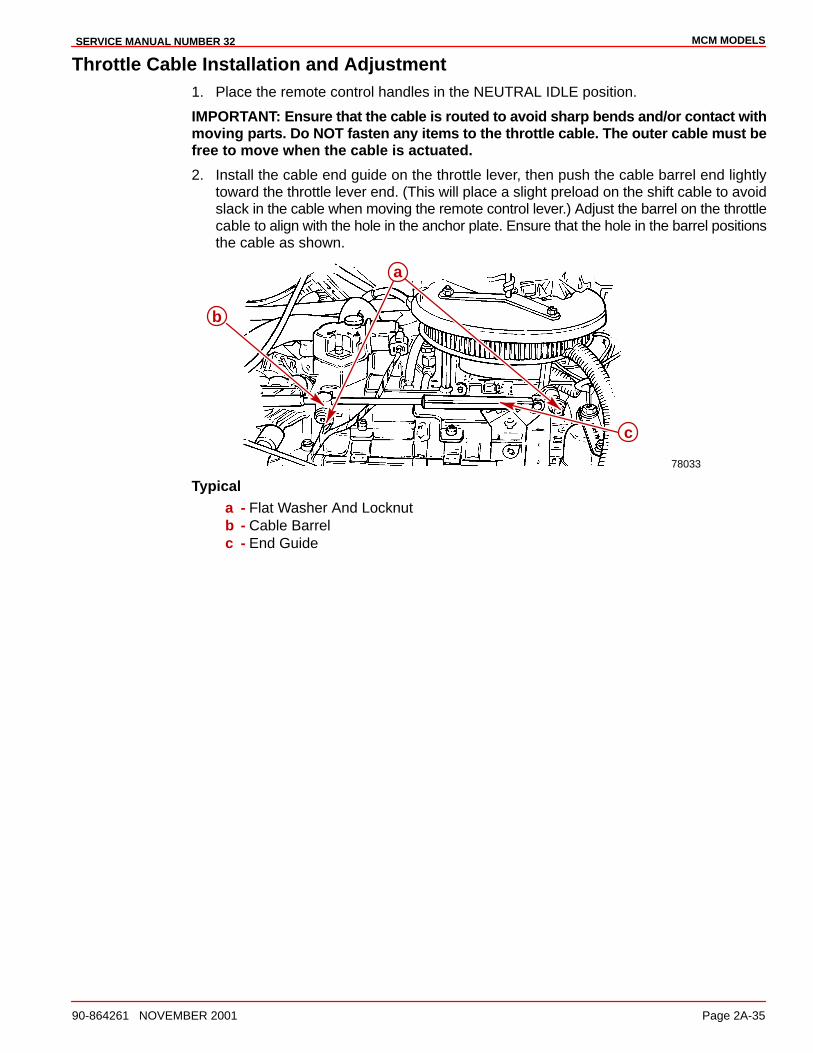
MCM MODELSSERVICE MANUAL NUMBER 32
90-864261 NOVEMBER 2001 Page 2A-35
Throttle Cable Installation and Adjustment1. Place the remote control handles in the NEUTRAL IDLE position.
IMPORTANT: Ensure that the cable is routed to avoid sharp bends and/or contact withmoving parts. Do NOT fasten any items to the throttle cable. The outer cable must befree to move when the cable is actuated.
2. Install the cable end guide on the throttle lever, then push the cable barrel end lightlytoward the throttle lever end. (This will place a slight preload on the shift cable to avoidslack in the cable when moving the remote control lever.) Adjust the barrel on the throttlecable to align with the hole in the anchor plate. Ensure that the hole in the barrel positionsthe cable as shown.
78033
a
c
b
Typicala - Flat Washer And Locknutb - Cable Barrelc - End Guide
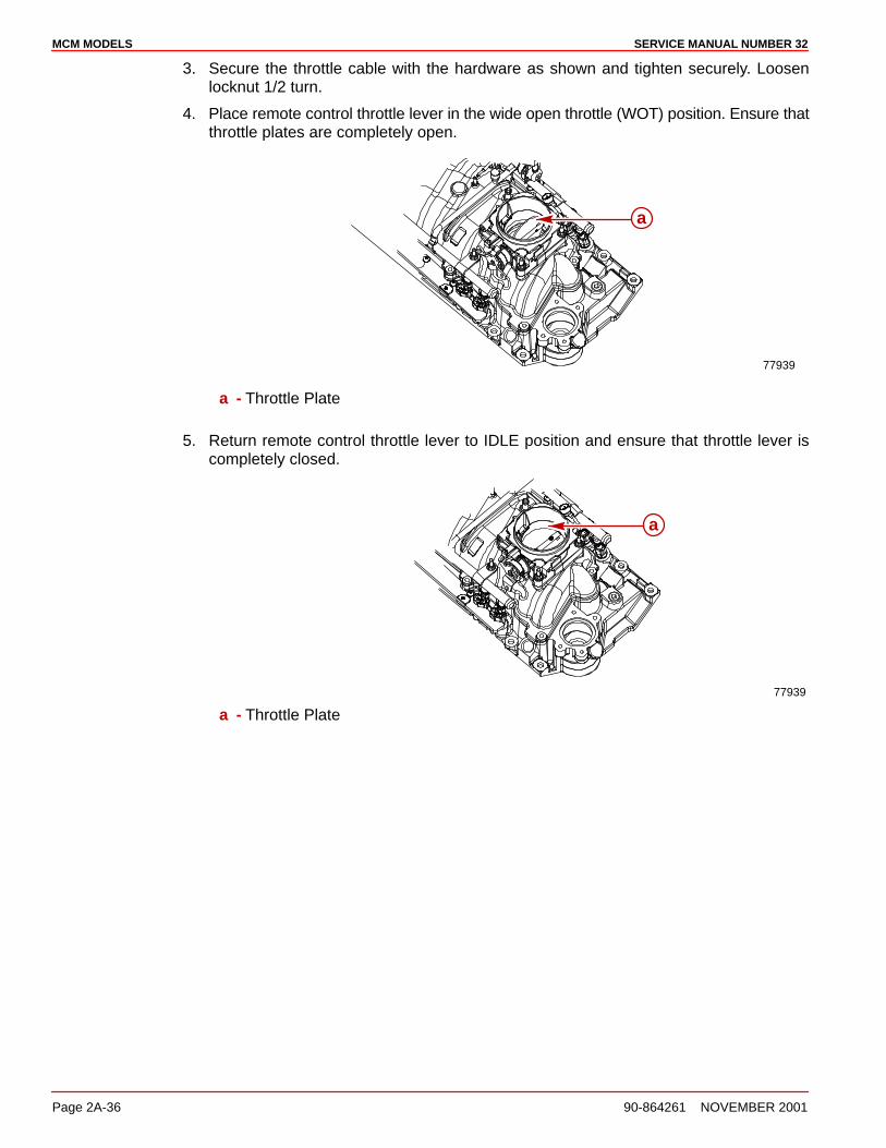
MCM MODELS SERVICE MANUAL NUMBER 32
Page 2A-36 90-864261 NOVEMBER 2001
3. Secure the throttle cable with the hardware as shown and tighten securely. Loosenlocknut 1/2 turn.
4. Place remote control throttle lever in the wide open throttle (WOT) position. Ensure thatthrottle plates are completely open.
77939
a
a - Throttle Plate
5. Return remote control throttle lever to IDLE position and ensure that throttle lever iscompletely closed.
77939
a
a - Throttle Plate
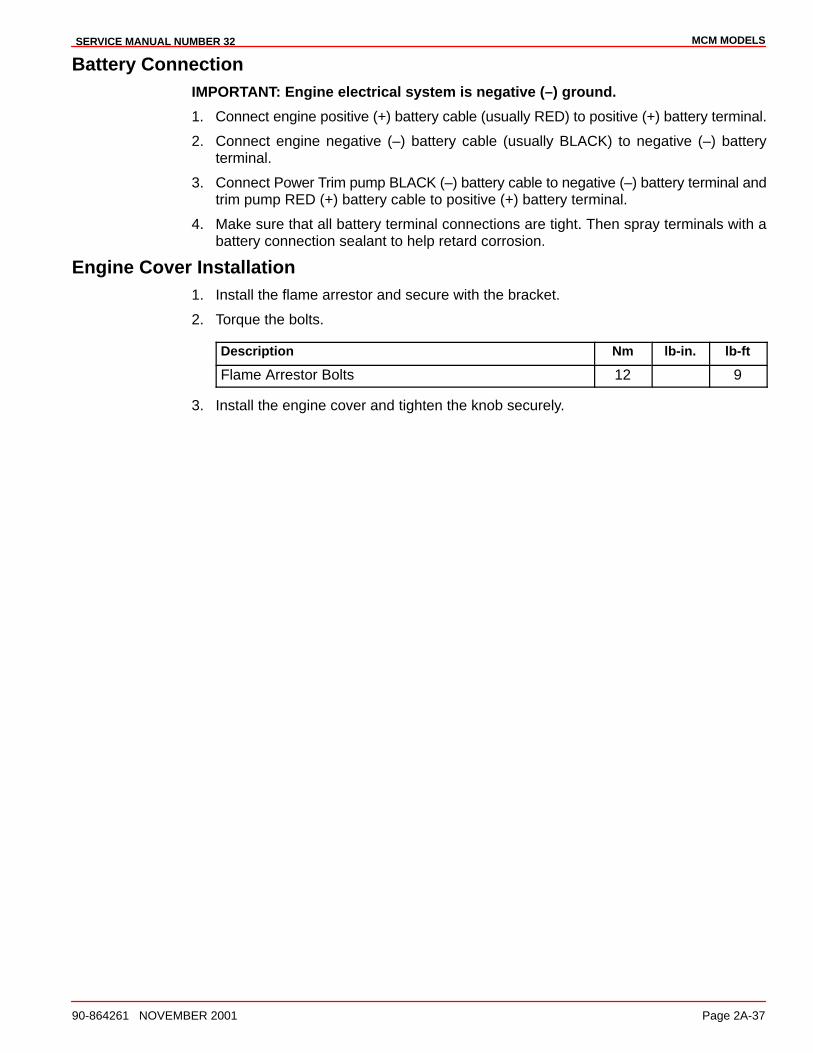
MCM MODELSSERVICE MANUAL NUMBER 32
90-864261 NOVEMBER 2001 Page 2A-37
Battery ConnectionIMPORTANT: Engine electrical system is negative (–) ground.
1. Connect engine positive (+) battery cable (usually RED) to positive (+) battery terminal.
2. Connect engine negative (–) battery cable (usually BLACK) to negative (–) batteryterminal.
3. Connect Power Trim pump BLACK (–) battery cable to negative (–) battery terminal andtrim pump RED (+) battery cable to positive (+) battery terminal.
4. Make sure that all battery terminal connections are tight. Then spray terminals with abattery connection sealant to help retard corrosion.
Engine Cover Installation1. Install the flame arrestor and secure with the bracket.
2. Torque the bolts.
Description Nm lb-in. lb-ft
Flame Arrestor Bolts 12 9
3. Install the engine cover and tighten the knob securely.
3A
ENGINE MECHANICALSERVICE MANUAL NUMBER 32
90-864261 NOVEMBER 2001 Page 3A-1
ENGINE MECHANICALSection 3A - 4.3 liter (262 cid)
Table of Contents
Identification 3A-3. . . . . . . . . . . . . . . . . . . . . . . .General Specifications 3A-4. . . . . . . . . . . . . . .
4.3 liter (262 cid) 3A-4. . . . . . . . . . . . . . . . .Engine Specifications - 4.3 liter (262 cid) 3A-5
Cylinder Head 3A-5. . . . . . . . . . . . . . . . . . . .Cylinder Bore 3A-5. . . . . . . . . . . . . . . . . . . .Oil Pump 3A-5. . . . . . . . . . . . . . . . . . . . . . . .Piston Bore Clearance 3A-5. . . . . . . . . . . .Piston Rings 3A-6. . . . . . . . . . . . . . . . . . . . .Piston Pin 3A-6. . . . . . . . . . . . . . . . . . . . . . .Crankshaft 3A-7. . . . . . . . . . . . . . . . . . . . . . .Connecting Rod 3A-8. . . . . . . . . . . . . . . . . .Valve 3A-8. . . . . . . . . . . . . . . . . . . . . . . . . . . .Valve (continued) 3A-9. . . . . . . . . . . . . . . . .Camshaft 3A-10. . . . . . . . . . . . . . . . . . . . . . . .Timing Chain 3A-10. . . . . . . . . . . . . . . . . . . . .Flywheel 3A-10. . . . . . . . . . . . . . . . . . . . . . . . .
Torque Specifications 3A-11. . . . . . . . . . . . . . . .Special Tools 3A-15. . . . . . . . . . . . . . . . . . . . . . .Lubricants / Sealants / Adhesives 3A-16. . . . .Precautions 3A-18. . . . . . . . . . . . . . . . . . . . . . . .General Information 3A-19. . . . . . . . . . . . . . . . .
Repair Procedures 3A-19. . . . . . . . . . . . . . . .Special Notice 3A-19. . . . . . . . . . . . . . . . . . . .Engine Rotation 3A-19. . . . . . . . . . . . . . . . . .Crankcase Oil Dipstick Measurements 3A-20
Engine Mounts 3A-21. . . . . . . . . . . . . . . . . . . . . .Exploded Views 3A-21. . . . . . . . . . . . . . . . . .
Valve Cover 3A-22. . . . . . . . . . . . . . . . . . . . . . . .Removal 3A-22. . . . . . . . . . . . . . . . . . . . . . . . .Cleaning and Inspection 3A-22. . . . . . . . . . .Installation 3A-23. . . . . . . . . . . . . . . . . . . . . . .
Rocker Arm / Valve Pushrod 3A-24. . . . . . . . . .Removal 3A-24. . . . . . . . . . . . . . . . . . . . . . . . .Cleaning 3A-25. . . . . . . . . . . . . . . . . . . . . . . . .Inspection 3A-25. . . . . . . . . . . . . . . . . . . . . . .Installation 3A-26. . . . . . . . . . . . . . . . . . . . . . .
Valve Stem Oil Seal / Valve Spring -Cylinder Head Installed 3A-28. . . . . . . . . . . . . .Exploded View 3A-28. . . . . . . . . . . . . . . . . . .Removal 3A-29. . . . . . . . . . . . . . . . . . . . . . . . .Installation 3A-30. . . . . . . . . . . . . . . . . . . . . . .
Intake Manifold Assembly 3A-33. . . . . . . . . . . .Exploded View 3A-33. . . . . . . . . . . . . . . . . . .Removal 3A-34. . . . . . . . . . . . . . . . . . . . . . . . .Cleaning 3A-35. . . . . . . . . . . . . . . . . . . . . . . . .Inspection 3A-35. . . . . . . . . . . . . . . . . . . . . . .Upper And Lower Intake Manifolds 3A-36. .Installation 3A-36. . . . . . . . . . . . . . . . . . . . . . .
Hydraulic Valve Lifters 3A-39. . . . . . . . . . . . . . .Exploded View 3A-39. . . . . . . . . . . . . . . . . . .Special Information 3A-39. . . . . . . . . . . . . . .Removal 3A-40. . . . . . . . . . . . . . . . . . . . . . . . .Cleaning 3A-41. . . . . . . . . . . . . . . . . . . . . . . . .Inspection 3A-41. . . . . . . . . . . . . . . . . . . . . . .Installation 3A-42. . . . . . . . . . . . . . . . . . . . . . .
Camshaft and Camshaft Bearings 3A-43. . . . .Measuring Camshaft Lobe Lift 3A-43. . . . . .Removal 3A-45. . . . . . . . . . . . . . . . . . . . . . . . .Cleaning 3A-49. . . . . . . . . . . . . . . . . . . . . . . . .Inspection 3A-50. . . . . . . . . . . . . . . . . . . . . . .Installation 3A-51. . . . . . . . . . . . . . . . . . . . . . .
Cylinder Head 3A-58. . . . . . . . . . . . . . . . . . . . . .Removal 3A-58. . . . . . . . . . . . . . . . . . . . . . . . .Disassembly 3A-59. . . . . . . . . . . . . . . . . . . . .Cleaning 3A-60. . . . . . . . . . . . . . . . . . . . . . . . .Inspection 3A-61. . . . . . . . . . . . . . . . . . . . . . .Repair 3A-66. . . . . . . . . . . . . . . . . . . . . . . . . . .Reassembly 3A-69. . . . . . . . . . . . . . . . . . . . .Installation 3A-73. . . . . . . . . . . . . . . . . . . . . . .
Oil Pan 3A-75. . . . . . . . . . . . . . . . . . . . . . . . . . . .Removal 3A-75. . . . . . . . . . . . . . . . . . . . . . . . .Cleaning 3A-76. . . . . . . . . . . . . . . . . . . . . . . . .Inspection 3A-76. . . . . . . . . . . . . . . . . . . . . . .Installation 3A-76. . . . . . . . . . . . . . . . . . . . . . .
Oil Pump 3A-78. . . . . . . . . . . . . . . . . . . . . . . . . . .Exploded View 3A-78. . . . . . . . . . . . . . . . . . .Removal 3A-79. . . . . . . . . . . . . . . . . . . . . . . . .Disassembly 3A-79. . . . . . . . . . . . . . . . . . . . .Cleaning 3A-80. . . . . . . . . . . . . . . . . . . . . . . . .Inspection 3A-81. . . . . . . . . . . . . . . . . . . . . . .Reassembly 3A-82. . . . . . . . . . . . . . . . . . . . .Installation 3A-84. . . . . . . . . . . . . . . . . . . . . . .
Crankshaft Balancer 3A-85. . . . . . . . . . . . . . . . .Removal 3A-85. . . . . . . . . . . . . . . . . . . . . . . . .Cleaning 3A-85. . . . . . . . . . . . . . . . . . . . . . . . .Inspection 3A-85. . . . . . . . . . . . . . . . . . . . . . .Installation 3A-86. . . . . . . . . . . . . . . . . . . . . . .
Front Cover Oil Seal 3A-88. . . . . . . . . . . . . . . . .Oil Seal ReplacementWithout Removing Front Cover 3A-88. . . .
Front Cover 3A-89. . . . . . . . . . . . . . . . . . . . . . . .Removal 3A-89. . . . . . . . . . . . . . . . . . . . . . . . .Cleaning and Inspection 3A-90. . . . . . . . . . .Installation 3A-90. . . . . . . . . . . . . . . . . . . . . . .
ENGINE MECHANICAL SERVICE MANUAL NUMBER 32
Page 3A-2 90-864261 NOVEMBER 2001
Connecting Rod, Bearingsand Piston Assembly 3A-92. . . . . . . . . . . . . . . .Exploded View 3A-92. . . . . . . . . . . . . . . . . . .Removal 3A-93. . . . . . . . . . . . . . . . . . . . . . . . .Disassembly 3A-95. . . . . . . . . . . . . . . . . . . . .Cleaning 3A-95. . . . . . . . . . . . . . . . . . . . . . . . .Inspection 3A-96. . . . . . . . . . . . . . . . . . . . . . .Reassembly 3A-111. . . . . . . . . . . . . . . . . . . . .Installation 3A-114. . . . . . . . . . . . . . . . . . . . . . .
Crankshaft, Main Bearingsand Engine Block 3A-118. . . . . . . . . . . . . . . . . . .Exploded View 3A-118. . . . . . . . . . . . . . . . . . .Removal 3A-119. . . . . . . . . . . . . . . . . . . . . . . . .Cleaning 3A-123. . . . . . . . . . . . . . . . . . . . . . . . .Inspection 3A-125. . . . . . . . . . . . . . . . . . . . . . .Installation 3A-137. . . . . . . . . . . . . . . . . . . . . . .
Timing Chain And Sprockets 3A-147. . . . . . . . . .Removal 3A-147. . . . . . . . . . . . . . . . . . . . . . . . .Cleaning 3A-148. . . . . . . . . . . . . . . . . . . . . . . . .Inspection 3A-148. . . . . . . . . . . . . . . . . . . . . . .Reassembly 3A-148. . . . . . . . . . . . . . . . . . . . .Installation 3A-150. . . . . . . . . . . . . . . . . . . . . . .
Flywheel Housing 3A-151. . . . . . . . . . . . . . . . . . .Removal 3A-151. . . . . . . . . . . . . . . . . . . . . . . . .Cleaning 3A-152. . . . . . . . . . . . . . . . . . . . . . . . .Inspection 3A-152. . . . . . . . . . . . . . . . . . . . . . .Installation 3A-152. . . . . . . . . . . . . . . . . . . . . . .
Flywheel 3A-153. . . . . . . . . . . . . . . . . . . . . . . . . . .Removal 3A-153. . . . . . . . . . . . . . . . . . . . . . . . .Cleaning and Inspection 3A-154. . . . . . . . . . .Installation 3A-154. . . . . . . . . . . . . . . . . . . . . . .
Rear Oil Seal 3A-156. . . . . . . . . . . . . . . . . . . . . . .Removal 3A-156. . . . . . . . . . . . . . . . . . . . . . . . .Cleaning 3A-156. . . . . . . . . . . . . . . . . . . . . . . . .Inspection 3A-156. . . . . . . . . . . . . . . . . . . . . . .Installation 3A-157. . . . . . . . . . . . . . . . . . . . . . .
Rear Oil Seal Retainer 3A-159. . . . . . . . . . . . . . .Removal 3A-159. . . . . . . . . . . . . . . . . . . . . . . . .Cleaning 3A-159. . . . . . . . . . . . . . . . . . . . . . . . .Inspection 3A-159. . . . . . . . . . . . . . . . . . . . . . .Installation 3A-160. . . . . . . . . . . . . . . . . . . . . . .
Oil Filter By-Pass Valve andBlock Adapter 3A-161. . . . . . . . . . . . . . . . . . . . . .Exploded View 3A-161. . . . . . . . . . . . . . . . . . .Removal 3A-162. . . . . . . . . . . . . . . . . . . . . . . . .Cleaning 3A-163. . . . . . . . . . . . . . . . . . . . . . . . .Inspection 3A-163. . . . . . . . . . . . . . . . . . . . . . .Installation 3A-164. . . . . . . . . . . . . . . . . . . . . . .
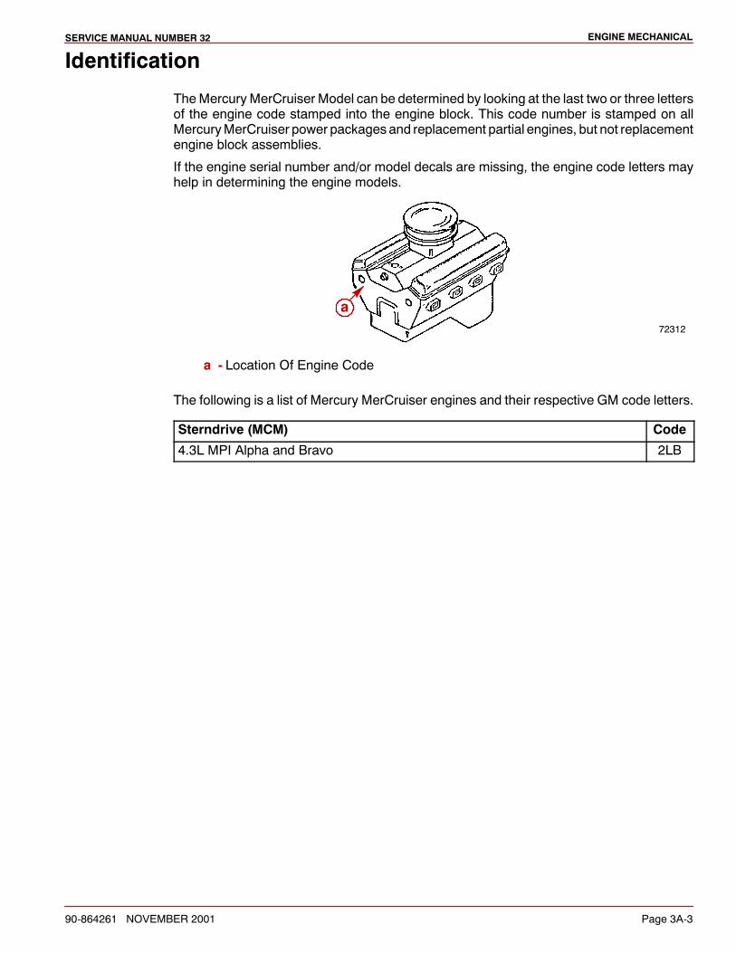
ENGINE MECHANICALSERVICE MANUAL NUMBER 32
90-864261 NOVEMBER 2001 Page 3A-3
Identification
TheMercury MerCruiser Model can be determined by looking at the last two or three lettersof the engine code stamped into the engine block. This code number is stamped on allMercuryMerCruiser power packages and replacement partial engines, but not replacementengine block assemblies.
If the engine serial number and/or model decals are missing, the engine code letters mayhelp in determining the engine models.
72312
a
a - Location Of Engine Code
The following is a list of Mercury MerCruiser engines and their respective GM code letters.
Sterndrive (MCM) Code
4.3L MPI Alpha and Bravo 2LB
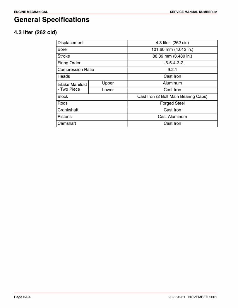
ENGINE MECHANICAL SERVICE MANUAL NUMBER 32
Page 3A-4 90-864261 NOVEMBER 2001
General Specifications
4.3 liter (262 cid)
Displacement 4.3 liter (262 cid)
Bore 101.60 mm (4.012 in.)
Stroke 88.39 mm (3.480 in.)
Firing Order 1-6-5-4-3-2
Compression Ratio 9.2:1
Heads Cast Iron
Intake Manifold Upper AluminumIntake Manifold- Two Piece Lower Cast Iron
Block Cast Iron (2 Bolt Main Bearing Caps)
Rods Forged Steel
Crankshaft Cast Iron
Pistons Cast Aluminum
Camshaft Cast Iron
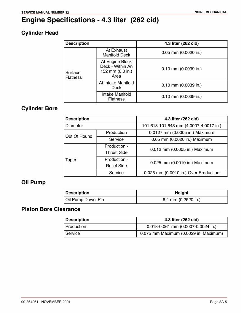
ENGINE MECHANICALSERVICE MANUAL NUMBER 32
90-864261 NOVEMBER 2001 Page 3A-5
Engine Specifications - 4.3 liter (262 cid)
Cylinder Head
Description 4.3 liter (262 cid)
At ExhaustManifold Deck 0.05 mm (0.0020 in.)
SurfaceFlatness
At Engine BlockDeck - Within An152 mm (6.0 in.)
Area
0.10 mm (0.0039 in.)
FlatnessAt Intake Manifold
Deck 0.10 mm (0.0039 in.)
Intake ManifoldFlatness 0.10 mm (0.0039 in.)
Cylinder Bore
Description 4.3 liter (262 cid)
Diameter 101.618-101.643 mm (4.0007-4.0017 in.)
Out Of RoundProduction 0.0127 mm (0.0005 in.) Maximum
Out Of RoundService 0.05 mm (0.0020 in.) Maximum
Production -Thrust Side
0.012 mm (0.0005 in.) Maximum
Taper Production -Relief Side
0.025 mm (0.0010 in.) Maximum
Service 0.025 mm (0.0010 in.) Over Production
Oil Pump
Description Height
Oil Pump Dowel Pin 6.4 mm (0.2520 in.)
Piston Bore Clearance
Description 4.3 liter (262 cid)
Production 0.018-0.061 mm (0.0007-0.0024 in.)
Service 0.075 mm Maximum (0.0029 in. Maximum)

ENGINE MECHANICAL SERVICE MANUAL NUMBER 32
Page 3A-6 90-864261 NOVEMBER 2001
Engine Specifications - 4.3 liter (262 cid) (continued)
Piston RingsTOP COMPRESSION
Description 4.3 liter (262 cid)
Groove Production 0.030-0.070 mm (0.0012-0.0028 in.)GrooveClearance Service 0.030-0.085 mm (0.0012-0.0033 in.)
GapProduction 0.25-0.40 mm (0.010-0.016 in.)
GapService 0.25-0.40 mm (0.010-0.020 in.)
SECOND COMPRESSION
Description 4.3 liter (262 cid)
Groove Production 0.040-0.080 mm (0.0015-0.0031 in.)GrooveClearance Service 0.030-0.085 mm (0.0012-0.0033 in.)
GapProduction 0.38-0.58 mm (0.015-0.023 in.)
GapService 0.38-0.80 mm (0.015-0.031 in.)
OIL CONTROL
Description 4.3 liter (262 cid)
Groove Production 0.046-0.196 mm (0.0018-0.0077 in.)
Clearance Service 0.046-0.200 mm (0.0018-0.0079 in.)
GapProduction 0.25-0.76 mm (0.0098-0.0299 in.)
GapService 0.005-0.090 mm (0.0002-0.0035 in.)
Piston Pin
Description 4.3 liter (262 cid)
Diameter 23.545-23.548 mm (0.9270-0.9271 in.)
ClearanceProduction 0.013-0.023 mm (0.0005-0.0009 in.)
ClearanceService Limit 0.025 mm Maximum (0.0010 in. Maximum)
Fit In Connecting Rod 0.012-0.048 mm (0.0005-0.0019 in.)Interference
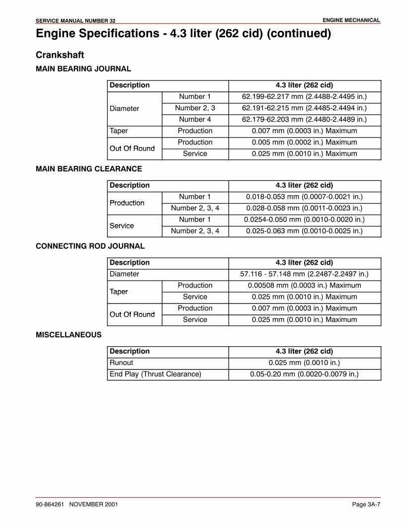
ENGINE MECHANICALSERVICE MANUAL NUMBER 32
90-864261 NOVEMBER 2001 Page 3A-7
Engine Specifications - 4.3 liter (262 cid) (continued)
CrankshaftMAIN BEARING JOURNAL
Description 4.3 liter (262 cid)
Number 1 62.199-62.217 mm (2.4488-2.4495 in.)
Diameter Number 2, 3 62.191-62.215 mm (2.4485-2.4494 in.)
Number 4 62.179-62.203 mm (2.4480-2.4489 in.)
Taper Production 0.007 mm (0.0003 in.) Maximum
Out Of RoundProduction 0.005 mm (0.0002 in.) Maximum
Out Of RoundService 0.025 mm (0.0010 in.) Maximum
MAIN BEARING CLEARANCE
Description 4.3 liter (262 cid)
ProductionNumber 1 0.018-0.053 mm (0.0007-0.0021 in.)
ProductionNumber 2, 3, 4 0.028-0.058 mm (0.0011-0.0023 in.)
ServiceNumber 1 0.0254-0.050 mm (0.0010-0.0020 in.)
ServiceNumber 2, 3, 4 0.025-0.063 mm (0.0010-0.0025 in.)
CONNECTING ROD JOURNAL
Description 4.3 liter (262 cid)
Diameter 57.116 - 57.148 mm (2.2487-2.2497 in.)
TaperProduction 0.00508 mm (0.0003 in.) Maximum
TaperService 0.025 mm (0.0010 in.) Maximum
Out Of RoundProduction 0.007 mm (0.0003 in.) Maximum
Out Of RoundService 0.025 mm (0.0010 in.) Maximum
MISCELLANEOUS
Description 4.3 liter (262 cid)
Runout 0.025 mm (0.0010 in.)
End Play (Thrust Clearance) 0.05-0.20 mm (0.0020-0.0079 in.)
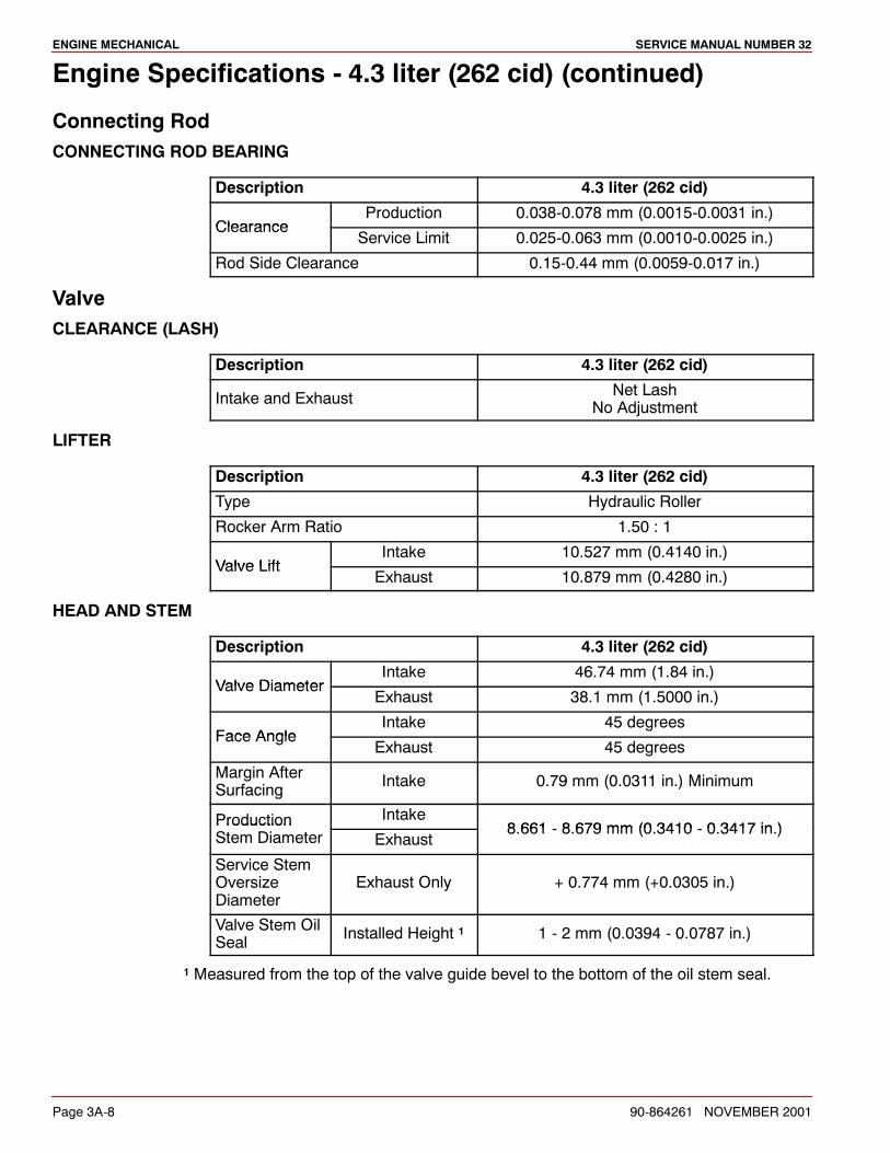
ENGINE MECHANICAL SERVICE MANUAL NUMBER 32
Page 3A-8 90-864261 NOVEMBER 2001
Engine Specifications - 4.3 liter (262 cid) (continued)
Connecting RodCONNECTING ROD BEARING
Description 4.3 liter (262 cid)
ClearanceProduction 0.038-0.078 mm (0.0015-0.0031 in.)
ClearanceService Limit 0.025-0.063 mm (0.0010-0.0025 in.)
Rod Side Clearance 0.15-0.44 mm (0.0059-0.017 in.)
ValveCLEARANCE (LASH)
Description 4.3 liter (262 cid)
Intake and Exhaust Net LashNo Adjustment
LIFTER
Description 4.3 liter (262 cid)
Type Hydraulic Roller
Rocker Arm Ratio 1.50 : 1
Valve LiftIntake 10.527 mm (0.4140 in.)
Valve LiftExhaust 10.879 mm (0.4280 in.)
HEAD AND STEM
Description 4.3 liter (262 cid)
Valve DiameterIntake 46.74 mm (1.84 in.)
Valve DiameterExhaust 38.1 mm (1.5000 in.)
Face AngleIntake 45 degrees
Face AngleExhaust 45 degrees
Margin AfterSurfacing Intake 0.79 mm (0.0311 in.) Minimum
Production Intake8 661 8 679 mm (0 3410 0 3417 in )Production
Stem Diameter Exhaust8.661 - 8.679 mm (0.3410 - 0.3417 in.)
Service StemOversizeDiameter
Exhaust Only + 0.774 mm (+0.0305 in.)
Valve Stem OilSeal Installed Height 1 1 - 2 mm (0.0394 - 0.0787 in.)
1 Measured from the top of the valve guide bevel to the bottom of the oil stem seal.
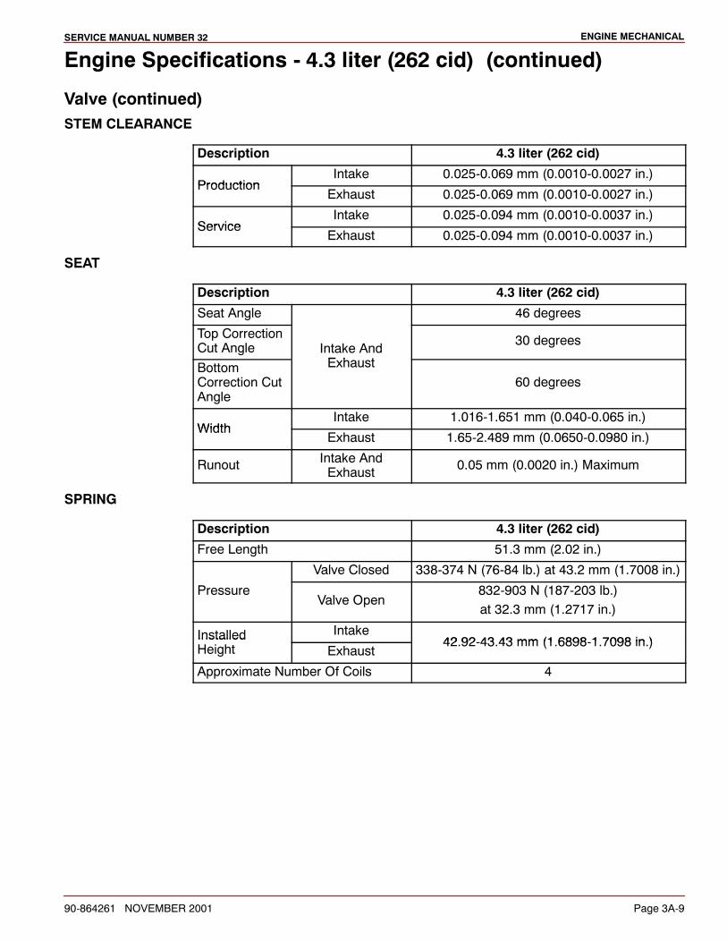
ENGINE MECHANICALSERVICE MANUAL NUMBER 32
90-864261 NOVEMBER 2001 Page 3A-9
Engine Specifications - 4.3 liter (262 cid) (continued)
Valve (continued)STEM CLEARANCE
Description 4.3 liter (262 cid)
ProductionIntake 0.025-0.069 mm (0.0010-0.0027 in.)
ProductionExhaust 0.025-0.069 mm (0.0010-0.0027 in.)
ServiceIntake 0.025-0.094 mm (0.0010-0.0037 in.)
ServiceExhaust 0.025-0.094 mm (0.0010-0.0037 in.)
SEAT
Description 4.3 liter (262 cid)
Seat Angle 46 degrees
Top CorrectionCut Angle Intake And
E h t
30 degrees
BottomCorrection CutAngle
Exhaust60 degrees
WidthIntake 1.016-1.651 mm (0.040-0.065 in.)
WidthExhaust 1.65-2.489 mm (0.0650-0.0980 in.)
Runout Intake AndExhaust 0.05 mm (0.0020 in.) Maximum
SPRING
Description 4.3 liter (262 cid)
Free Length 51.3 mm (2.02 in.)
Valve Closed 338-374 N (76-84 lb.) at 43.2 mm (1.7008 in.)
PressureValve Open
832-903 N (187-203 lb.)at 32.3 mm (1.2717 in.)
Installed Intake42 92 43 43 mm (1 6898 1 7098 in )Installed
Height Exhaust42.92-43.43 mm (1.6898-1.7098 in.)
Approximate Number Of Coils 4
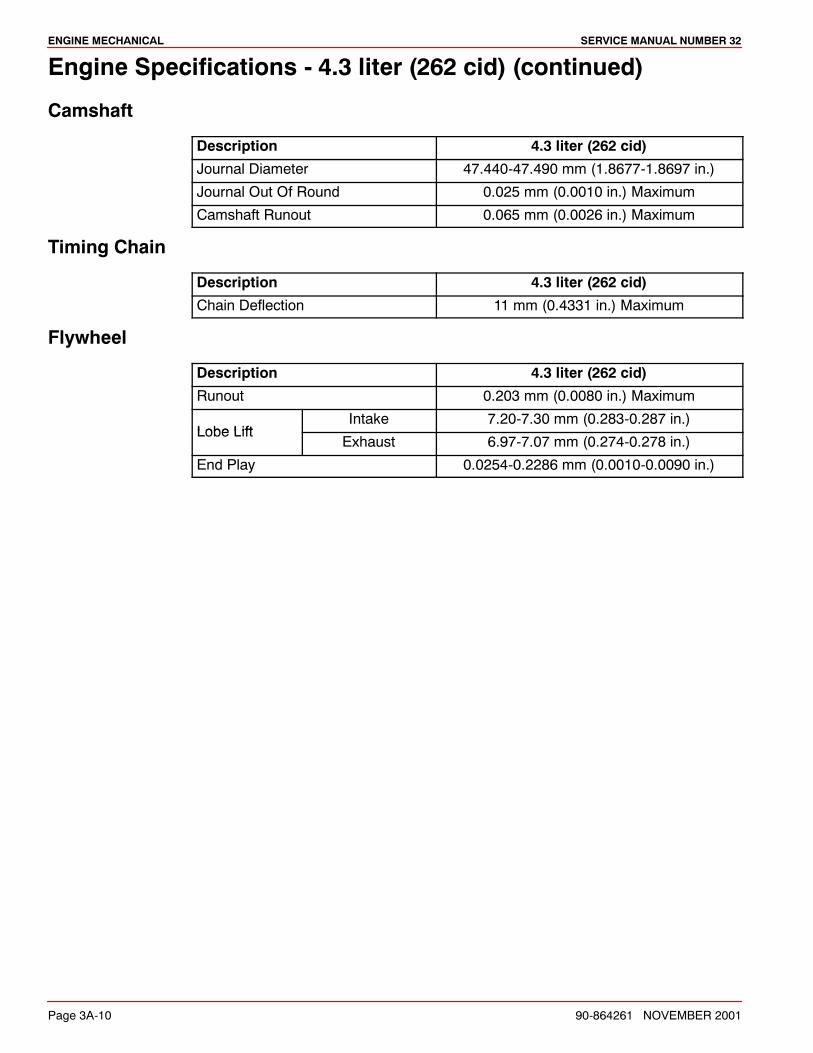
ENGINE MECHANICAL SERVICE MANUAL NUMBER 32
Page 3A-10 90-864261 NOVEMBER 2001
Engine Specifications - 4.3 liter (262 cid) (continued)
Camshaft
Description 4.3 liter (262 cid)
Journal Diameter 47.440-47.490 mm (1.8677-1.8697 in.)
Journal Out Of Round 0.025 mm (0.0010 in.) Maximum
Camshaft Runout 0.065 mm (0.0026 in.) Maximum
Timing Chain
Description 4.3 liter (262 cid)
Chain Deflection 11 mm (0.4331 in.) Maximum
Flywheel
Description 4.3 liter (262 cid)
Runout 0.203 mm (0.0080 in.) Maximum
Lobe LiftIntake 7.20-7.30 mm (0.283-0.287 in.)
Lobe LiftExhaust 6.97-7.07 mm (0.274-0.278 in.)
End Play 0.0254-0.2286 mm (0.0010-0.0090 in.)
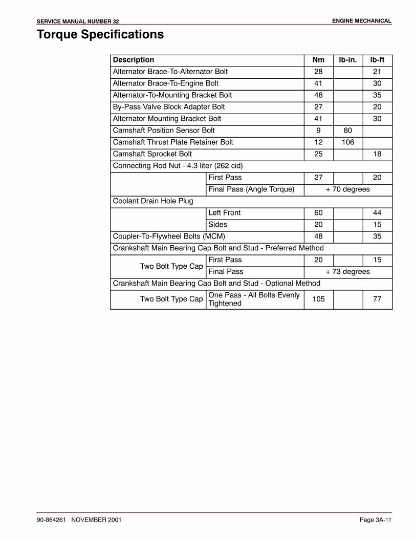
ENGINE MECHANICALSERVICE MANUAL NUMBER 32
90-864261 NOVEMBER 2001 Page 3A-11
Torque Specifications
Description Nm lb-in. lb-ft
Alternator Brace-To-Alternator Bolt 28 21
Alternator Brace-To-Engine Bolt 41 30
Alternator-To-Mounting Bracket Bolt 48 35
By-Pass Valve Block Adapter Bolt 27 20
Alternator Mounting Bracket Bolt 41 30
Camshaft Position Sensor Bolt 9 80
Camshaft Thrust Plate Retainer Bolt 12 106
Camshaft Sprocket Bolt 25 18
Connecting Rod Nut - 4.3 liter (262 cid)
First Pass 27 20
Final Pass (Angle Torque) + 70 degrees
Coolant Drain Hole Plug
Left Front 60 44
Sides 20 15
Coupler-To-Flywheel Bolts (MCM) 48 35
Crankshaft Main Bearing Cap Bolt and Stud - Preferred Method
Two Bolt Type CapFirst Pass 20 15
Two Bolt Type CapFinal Pass + 73 degrees
Crankshaft Main Bearing Cap Bolt and Stud - Optional Method
Two Bolt Type Cap One Pass - All Bolts EvenlyTightened 105 77
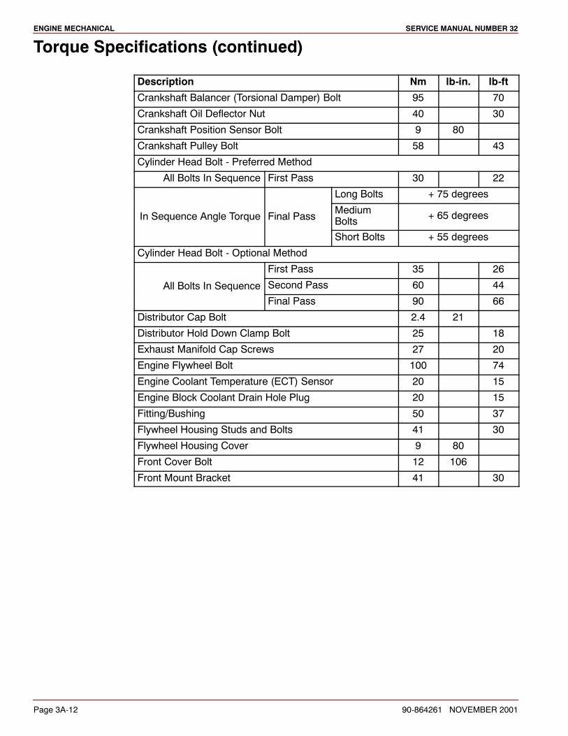
ENGINE MECHANICAL SERVICE MANUAL NUMBER 32
Page 3A-12 90-864261 NOVEMBER 2001
Torque Specifications (continued)
Description Nm lb-in. lb-ft
Crankshaft Balancer (Torsional Damper) Bolt 95 70
Crankshaft Oil Deflector Nut 40 30
Crankshaft Position Sensor Bolt 9 80
Crankshaft Pulley Bolt 58 43
Cylinder Head Bolt - Preferred Method
All Bolts In Sequence First Pass 30 22
Long Bolts + 75 degrees
In Sequence Angle Torque Final PassMediumBolts + 65 degrees
Short Bolts + 55 degrees
Cylinder Head Bolt - Optional Method
First Pass 35 26
All Bolts In Sequence Second Pass 60 44qFinal Pass 90 66
Distributor Cap Bolt 2.4 21
Distributor Hold Down Clamp Bolt 25 18
Exhaust Manifold Cap Screws 27 20
Engine Flywheel Bolt 100 74
Engine Coolant Temperature (ECT) Sensor 20 15
Engine Block Coolant Drain Hole Plug 20 15
Fitting/Bushing 50 37
Flywheel Housing Studs and Bolts 41 30
Flywheel Housing Cover 9 80
Front Cover Bolt 12 106
Front Mount Bracket 41 30
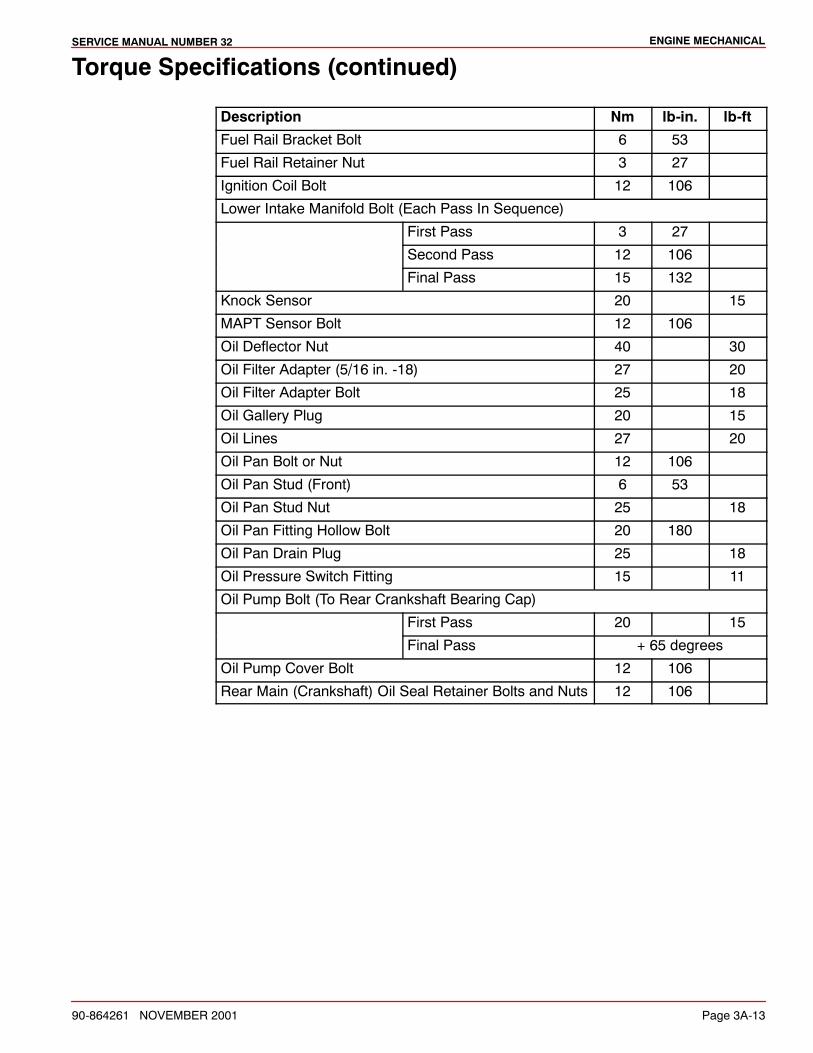
ENGINE MECHANICALSERVICE MANUAL NUMBER 32
90-864261 NOVEMBER 2001 Page 3A-13
Torque Specifications (continued)
Description Nm lb-in. lb-ft
Fuel Rail Bracket Bolt 6 53
Fuel Rail Retainer Nut 3 27
Ignition Coil Bolt 12 106
Lower Intake Manifold Bolt (Each Pass In Sequence)
First Pass 3 27
Second Pass 12 106
Final Pass 15 132
Knock Sensor 20 15
MAPT Sensor Bolt 12 106
Oil Deflector Nut 40 30
Oil Filter Adapter (5/16 in. -18) 27 20
Oil Filter Adapter Bolt 25 18
Oil Gallery Plug 20 15
Oil Lines 27 20
Oil Pan Bolt or Nut 12 106
Oil Pan Stud (Front) 6 53
Oil Pan Stud Nut 25 18
Oil Pan Fitting Hollow Bolt 20 180
Oil Pan Drain Plug 25 18
Oil Pressure Switch Fitting 15 11
Oil Pump Bolt (To Rear Crankshaft Bearing Cap)
First Pass 20 15
Final Pass + 65 degrees
Oil Pump Cover Bolt 12 106
Rear Main (Crankshaft) Oil Seal Retainer Bolts and Nuts 12 106
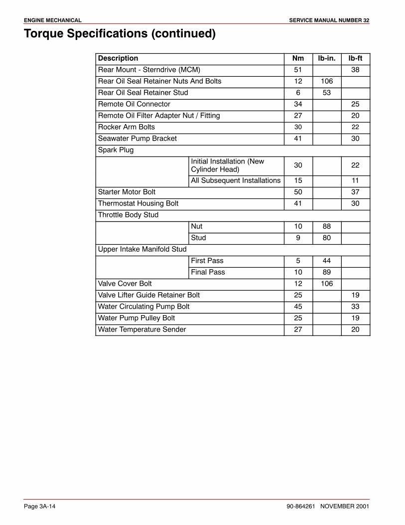
ENGINE MECHANICAL SERVICE MANUAL NUMBER 32
Page 3A-14 90-864261 NOVEMBER 2001
Torque Specifications (continued)
Description Nm lb-in. lb-ft
Rear Mount - Sterndrive (MCM) 51 38
Rear Oil Seal Retainer Nuts And Bolts 12 106
Rear Oil Seal Retainer Stud 6 53
Remote Oil Connector 34 25
Remote Oil Filter Adapter Nut / Fitting 27 20
Rocker Arm Bolts 30 22
Seawater Pump Bracket 41 30
Spark Plug
Initial Installation (NewCylinder Head) 30 22
All Subsequent Installations 15 11
Starter Motor Bolt 50 37
Thermostat Housing Bolt 41 30
Throttle Body Stud
Nut 10 88
Stud 9 80
Upper Intake Manifold Stud
First Pass 5 44
Final Pass 10 89
Valve Cover Bolt 12 106
Valve Lifter Guide Retainer Bolt 25 19
Water Circulating Pump Bolt 45 33
Water Pump Pulley Bolt 25 19
Water Temperature Sender 27 20
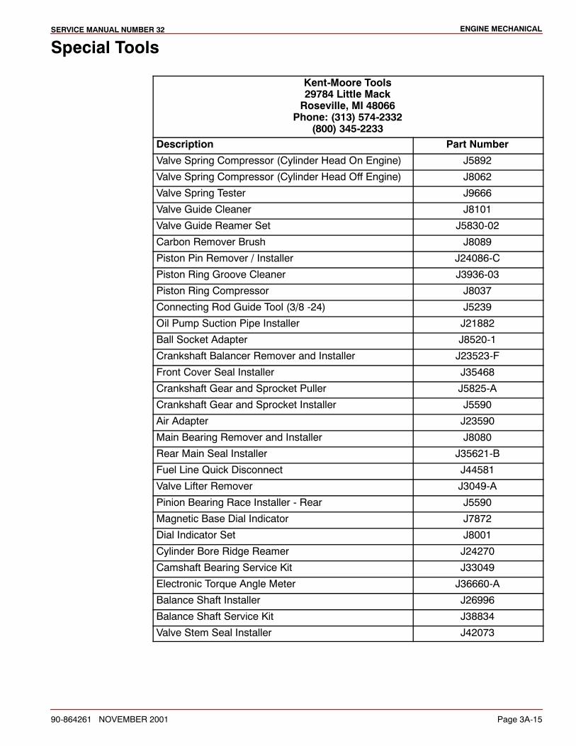
ENGINE MECHANICALSERVICE MANUAL NUMBER 32
90-864261 NOVEMBER 2001 Page 3A-15
Special Tools
Kent-Moore Tools29784 Little MackRoseville, MI 48066
Phone: (313) 574-2332(800) 345-2233
Description Part Number
Valve Spring Compressor (Cylinder Head On Engine) J5892
Valve Spring Compressor (Cylinder Head Off Engine) J8062
Valve Spring Tester J9666
Valve Guide Cleaner J8101
Valve Guide Reamer Set J5830-02
Carbon Remover Brush J8089
Piston Pin Remover / Installer J24086-C
Piston Ring Groove Cleaner J3936-03
Piston Ring Compressor J8037
Connecting Rod Guide Tool (3/8 -24) J5239
Oil Pump Suction Pipe Installer J21882
Ball Socket Adapter J8520-1
Crankshaft Balancer Remover and Installer J23523-F
Front Cover Seal Installer J35468
Crankshaft Gear and Sprocket Puller J5825-A
Crankshaft Gear and Sprocket Installer J5590
Air Adapter J23590
Main Bearing Remover and Installer J8080
Rear Main Seal Installer J35621-B
Fuel Line Quick Disconnect J44581
Valve Lifter Remover J3049-A
Pinion Bearing Race Installer - Rear J5590
Magnetic Base Dial Indicator J7872
Dial Indicator Set J8001
Cylinder Bore Ridge Reamer J24270
Camshaft Bearing Service Kit J33049
Electronic Torque Angle Meter J36660-A
Balance Shaft Installer J26996
Balance Shaft Service Kit J38834
Valve Stem Seal Installer J42073
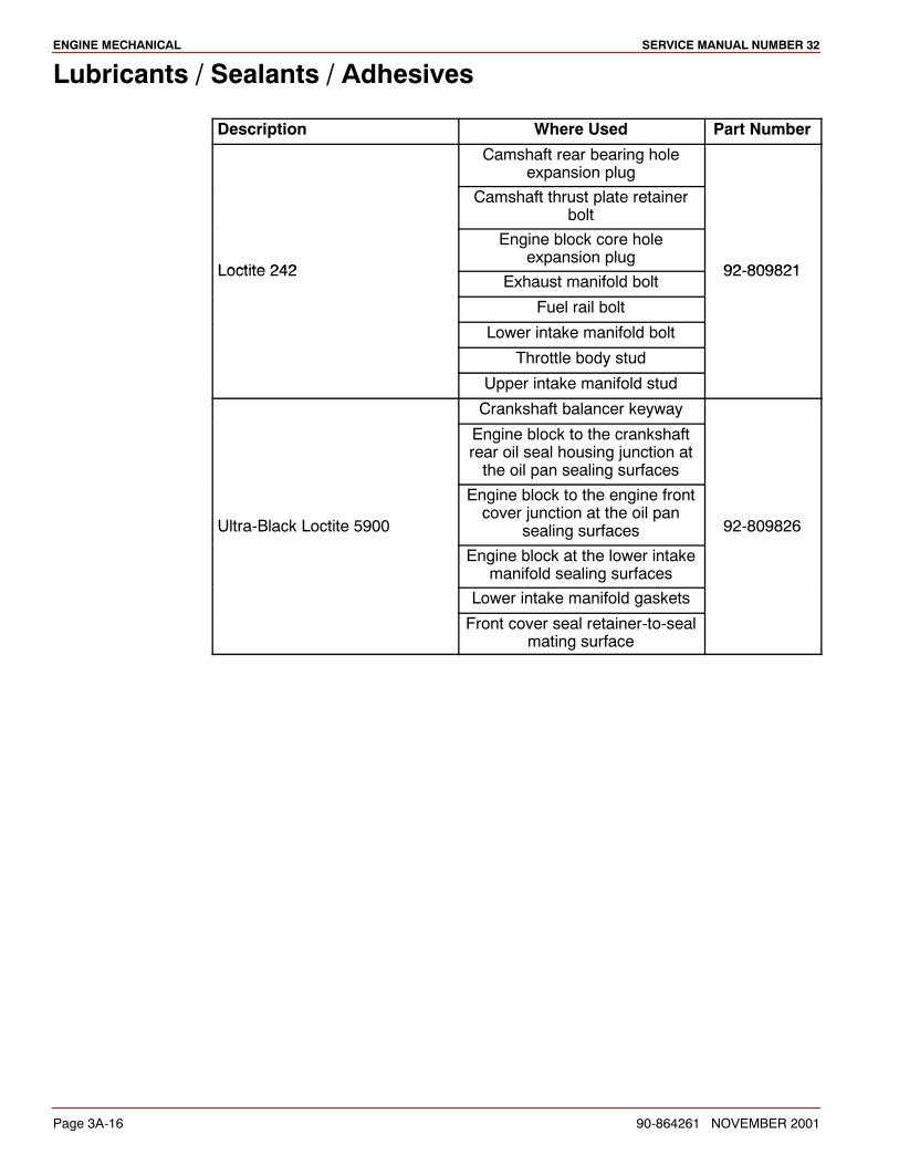
ENGINE MECHANICAL SERVICE MANUAL NUMBER 32
Page 3A-16 90-864261 NOVEMBER 2001
Lubricants / Sealants / Adhesives
Description Where Used Part Number
Camshaft rear bearing holeexpansion plug
Camshaft thrust plate retainerbolt
Loctite 242
Engine block core holeexpansion plug
92 809821Loctite 242Exhaust manifold bolt
92-809821
Fuel rail bolt
Lower intake manifold bolt
Throttle body stud
Upper intake manifold stud
Crankshaft balancer keyway
Engine block to the crankshaftrear oil seal housing junction atthe oil pan sealing surfaces
Ultra-Black Loctite 5900
Engine block to the engine frontcover junction at the oil pan
sealing surfaces 92-809826
Engine block at the lower intakemanifold sealing surfaces
Lower intake manifold gaskets
Front cover seal retainer-to-sealmating surface
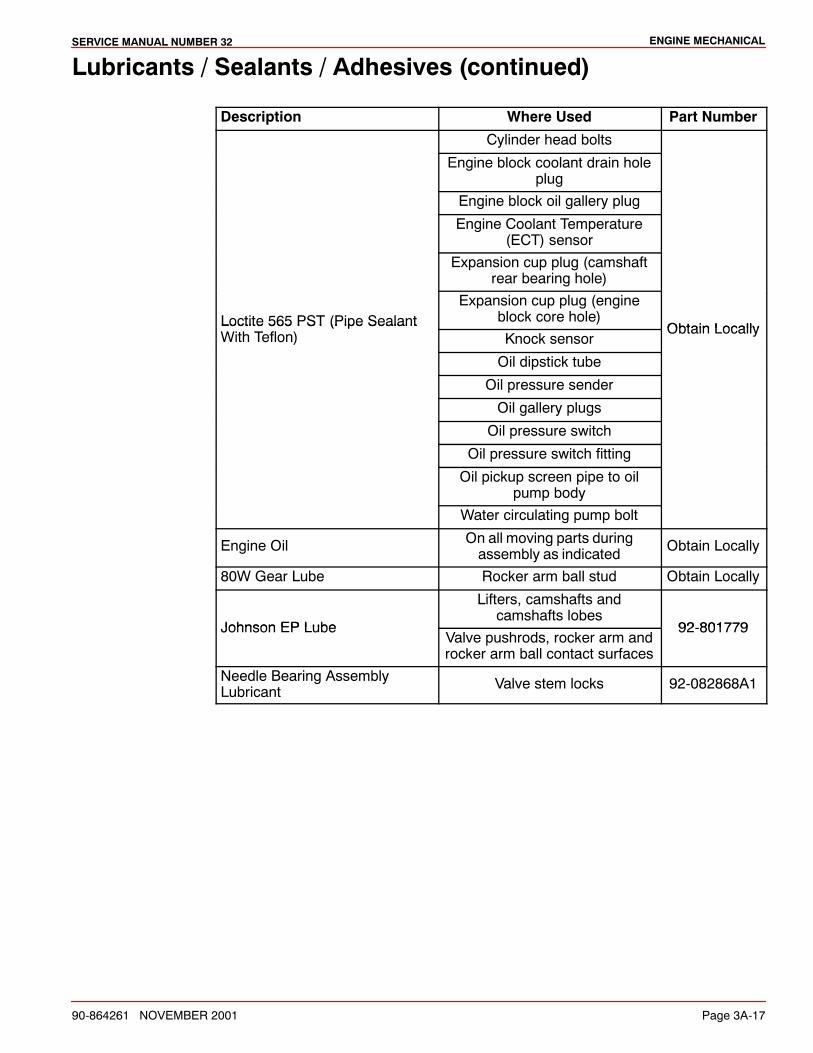
ENGINE MECHANICALSERVICE MANUAL NUMBER 32
90-864261 NOVEMBER 2001 Page 3A-17
Lubricants / Sealants / Adhesives (continued)
Description Where Used Part Number
Cylinder head bolts
Engine block coolant drain holeplug
Engine block oil gallery plug
Engine Coolant Temperature(ECT) sensor
Expansion cup plug (camshaftrear bearing hole)
Loctite 565 PST (Pipe SealantExpansion cup plug (engine
block core hole)Obtain LocallyLoctite 565 PST (Pipe Sealant
With Teflon) Knock sensorObtain Locally
Oil dipstick tube
Oil pressure sender
Oil gallery plugs
Oil pressure switch
Oil pressure switch fitting
Oil pickup screen pipe to oilpump body
Water circulating pump bolt
Engine Oil On all moving parts duringassembly as indicated Obtain Locally
80W Gear Lube Rocker arm ball stud Obtain Locally
Johnson EP Lube
Lifters, camshafts andcamshafts lobes
92 801779Johnson EP LubeValve pushrods, rocker arm androcker arm ball contact surfaces
92-801779
Needle Bearing AssemblyLubricant Valve stem locks 92-082868A1
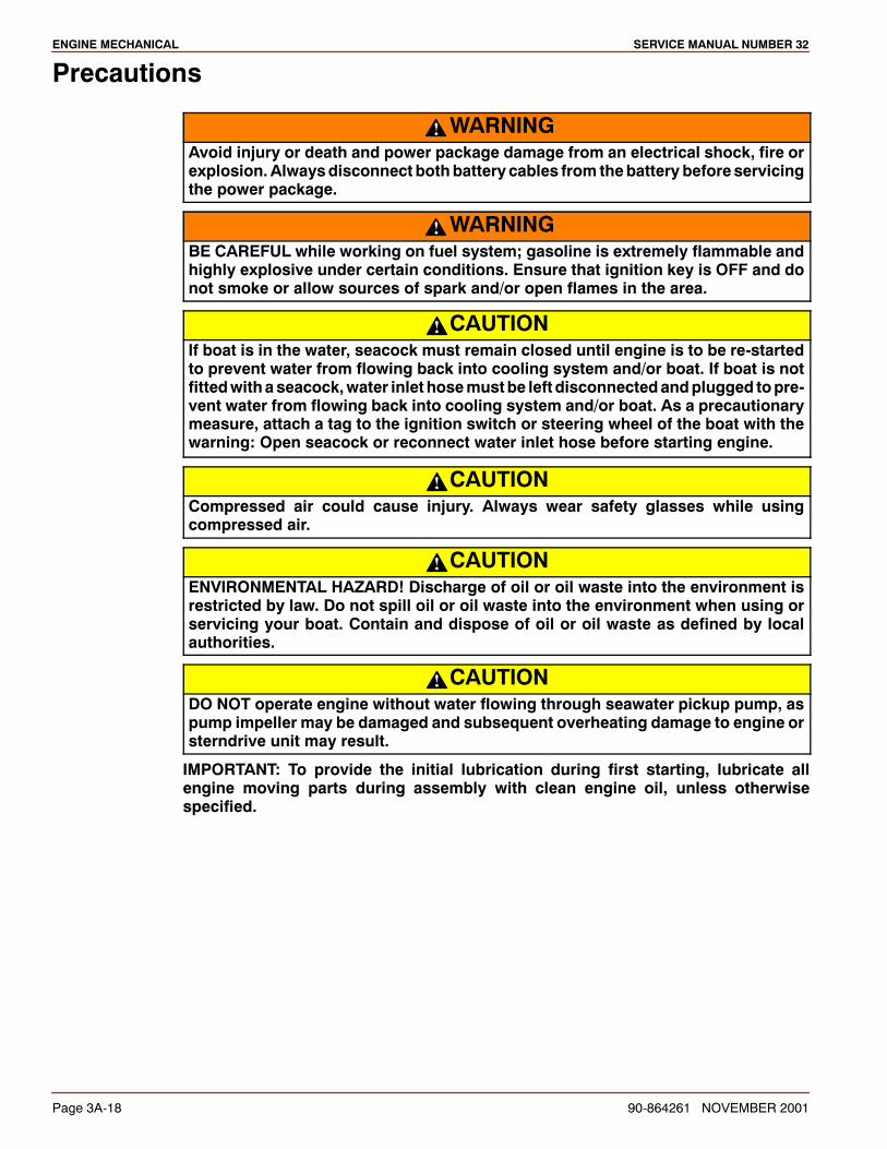
ENGINE MECHANICAL SERVICE MANUAL NUMBER 32
Page 3A-18 90-864261 NOVEMBER 2001
Precautions
WARNINGAvoid injury or death and power package damage from an electrical shock, fire orexplosion.Alwaysdisconnect bothbattery cables from thebattery before servicingthe power package.
WARNINGBE CAREFUL while working on fuel system; gasoline is extremely flammable andhighly explosive under certain conditions. Ensure that ignition key is OFF and donot smoke or allow sources of spark and/or open flames in the area.
CAUTIONIf boat is in the water, seacock must remain closed until engine is to be re-startedto prevent water from flowing back into cooling system and/or boat. If boat is notfittedwithaseacock,water inlet hosemustbe left disconnectedandplugged topre-vent water from flowing back into cooling system and/or boat. As a precautionarymeasure, attach a tag to the ignition switch or steering wheel of the boat with thewarning: Open seacock or reconnect water inlet hose before starting engine.
CAUTIONCompressed air could cause injury. Always wear safety glasses while usingcompressed air.
CAUTIONENVIRONMENTAL HAZARD! Discharge of oil or oil waste into the environment isrestricted by law. Do not spill oil or oil waste into the environment when using orservicing your boat. Contain and dispose of oil or oil waste as defined by localauthorities.
CAUTIONDO NOT operate engine without water flowing through seawater pickup pump, aspump impeller may be damaged and subsequent overheating damage to engine orsterndrive unit may result.
IMPORTANT: To provide the initial lubrication during first starting, lubricate allengine moving parts during assembly with clean engine oil, unless otherwisespecified.

ENGINE MECHANICALSERVICE MANUAL NUMBER 32
90-864261 NOVEMBER 2001 Page 3A-19
General Information
Repair ProceduresSome of the repairs in this section must be completed with the engine removed from theboat. Engine removal depends upon the type of repair and boat design. Place the engineon a repair stand for major repairs.
When engine removal is not required, ensure that the battery cables are disconnected atthe battery prior to performing any on-board repair procedures.
Lubricate all moving parts during reassembly with clean engine oil or as specified. Applyappropriate lubricant, sealant or adhesive to all fasteners as specified.
Special NoticeServicing the cylinder heads and engine block is the primary concern of this section. Someexternal components that are not mentioned in the procedural steps must be removed.Refer to appropriate sections of this manual for complete service information concerningany component hindering service or repairs to the cylinder heads and engine block.
Engine RotationEngine rotation is described when observed from the rear of the engine (sterndrive end)looking forward (water pump end).
Propeller rotation is not necessarily the same as engine rotation.
IMPORTANT: All engines covered by this service manual are left hand (LH) rotation.
72001
a
a - Left Hand Rotation (Counterclockwise)
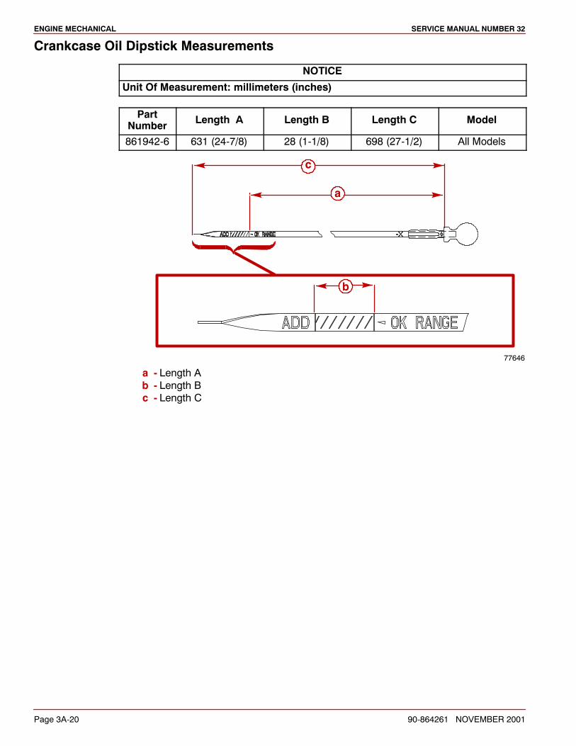
ENGINE MECHANICAL SERVICE MANUAL NUMBER 32
Page 3A-20 90-864261 NOVEMBER 2001
Crankcase Oil Dipstick Measurements
NOTICE
Unit Of Measurement: millimeters (inches)
PartNumber Length A Length B Length C Model
861942-6 631 (24-7/8) 28 (1-1/8) 698 (27-1/2) All Models
77646
c
a
b
a - Length Ab - Length Bc - Length C
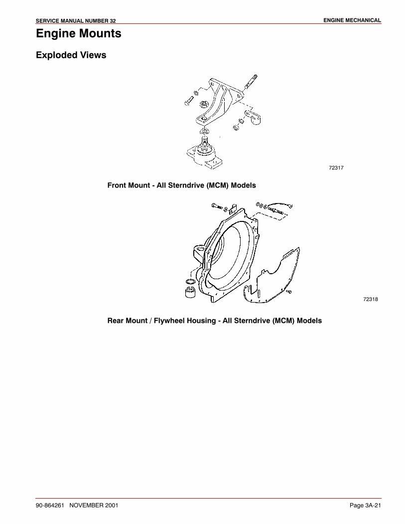
ENGINE MECHANICALSERVICE MANUAL NUMBER 32
90-864261 NOVEMBER 2001 Page 3A-21
Engine Mounts
Exploded Views
72317
Front Mount - All Sterndrive (MCM) Models
72318
Rear Mount / Flywheel Housing - All Sterndrive (MCM) Models

ENGINE MECHANICAL SERVICE MANUAL NUMBER 32
Page 3A-22 90-864261 NOVEMBER 2001
Valve Cover
RemovalNOTE: It may be necessary to remove the exhaust manifold before removing a valve cover.Refer to SECTION 7 for exhaust manifold removal.
1. Disconnect crankcase ventilation hoses.
2. Remove any items that interfere with the removal of valve covers.
3. Remove valve covers.
Cleaning and Inspection1. Clean gasket material from all sealing surfaces.
2. Put on safety glasses.
78221
3. Clean sealing surfaces on cylinder head and valve cover with degreaser.
ENGINE MECHANICALSERVICE MANUAL NUMBER 32
90-864261 NOVEMBER 2001 Page 3A-23
Installation1. Place new valve cover gasket in groove on valve cover.
2. Install valve cover. Torque bolts.
Description Nm lb-in. lb-ft
Valve Cover Bolt 12 106
3. Install any items that were removed.
4. Connect crankcase ventilation hoses.
5. Supply cooling water to the power package.
6. Start engine and check for oil leaks.
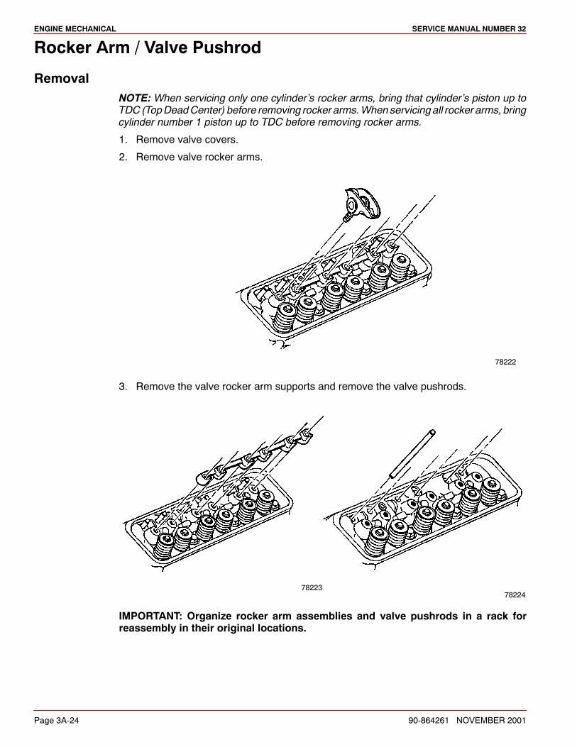
ENGINE MECHANICAL SERVICE MANUAL NUMBER 32
Page 3A-24 90-864261 NOVEMBER 2001
Rocker Arm / Valve Pushrod
RemovalNOTE: When servicing only one cylinder’s rocker arms, bring that cylinder’s piston up toTDC (TopDeadCenter) before removing rocker arms.When servicing all rocker arms, bringcylinder number 1 piston up to TDC before removing rocker arms.
1. Remove valve covers.
2. Remove valve rocker arms.
78222
3. Remove the valve rocker arm supports and remove the valve pushrods.
7822378224
IMPORTANT: Organize rocker arm assemblies and valve pushrods in a rack forreassembly in their original locations.
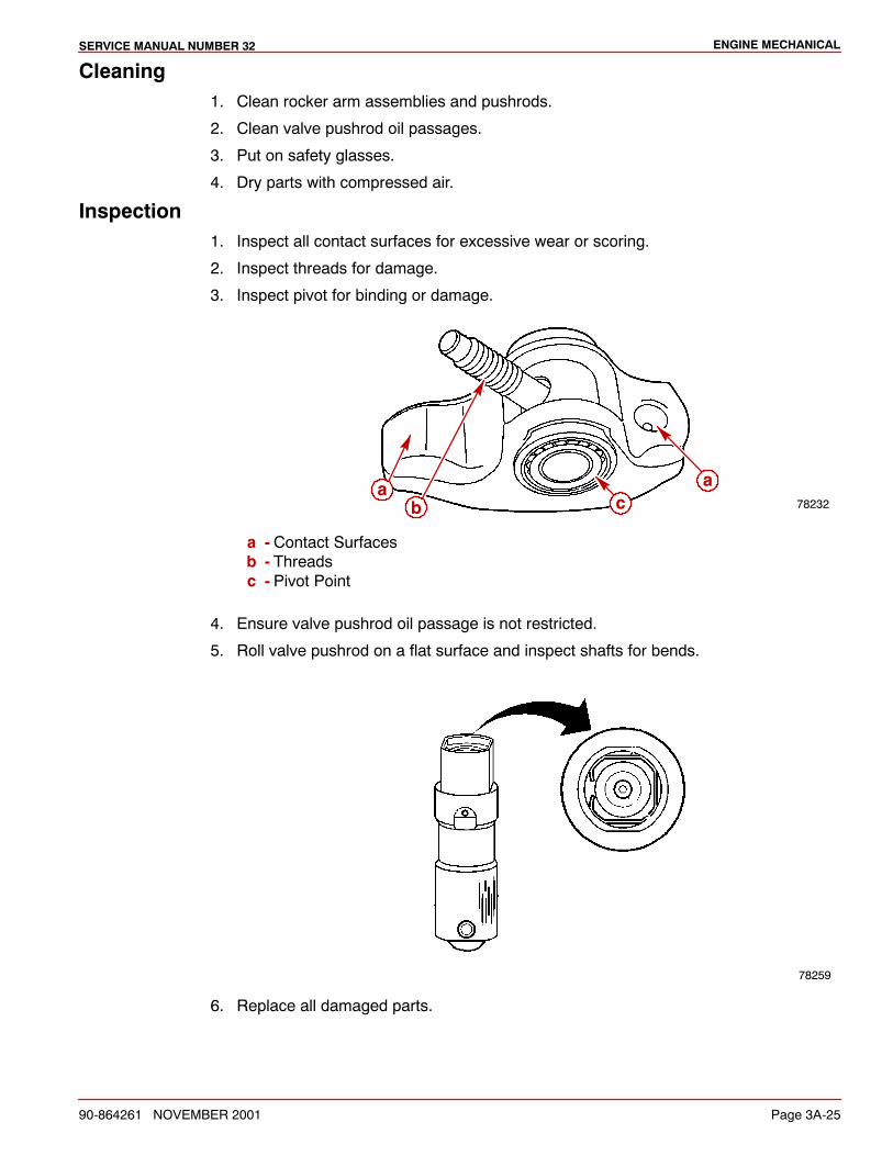
ENGINE MECHANICALSERVICE MANUAL NUMBER 32
90-864261 NOVEMBER 2001 Page 3A-25
Cleaning1. Clean rocker arm assemblies and pushrods.
2. Clean valve pushrod oil passages.
3. Put on safety glasses.
4. Dry parts with compressed air.
Inspection1. Inspect all contact surfaces for excessive wear or scoring.
2. Inspect threads for damage.
3. Inspect pivot for binding or damage.
78232b
aac
a - Contact Surfacesb - Threadsc - Pivot Point
4. Ensure valve pushrod oil passage is not restricted.
5. Roll valve pushrod on a flat surface and inspect shafts for bends.
78259
6. Replace all damaged parts.
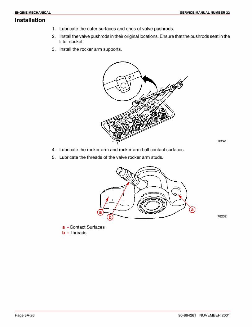
ENGINE MECHANICAL SERVICE MANUAL NUMBER 32
Page 3A-26 90-864261 NOVEMBER 2001
Installation1. Lubricate the outer surfaces and ends of valve pushrods.
2. Install the valve pushrods in their original locations. Ensure that the pushrods seat in thelifter socket.
3. Install the rocker arm supports.
78241
4. Lubricate the rocker arm and rocker arm ball contact surfaces.
5. Lubricate the threads of the valve rocker arm studs.
78232b
aa
a - Contact Surfacesb - Threads
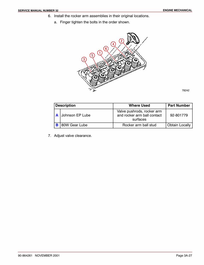
ENGINE MECHANICALSERVICE MANUAL NUMBER 32
90-864261 NOVEMBER 2001 Page 3A-27
6. Install the rocker arm assemblies in their original locations.
a. Finger tighten the bolts in the order shown.
78242
1
2
3
4
5
6
Description Where Used Part Number
A Johnson EP LubeValve pushrods, rocker armand rocker arm ball contact
surfaces92-801779
B 80W Gear Lube Rocker arm ball stud Obtain Locally
7. Adjust valve clearance.
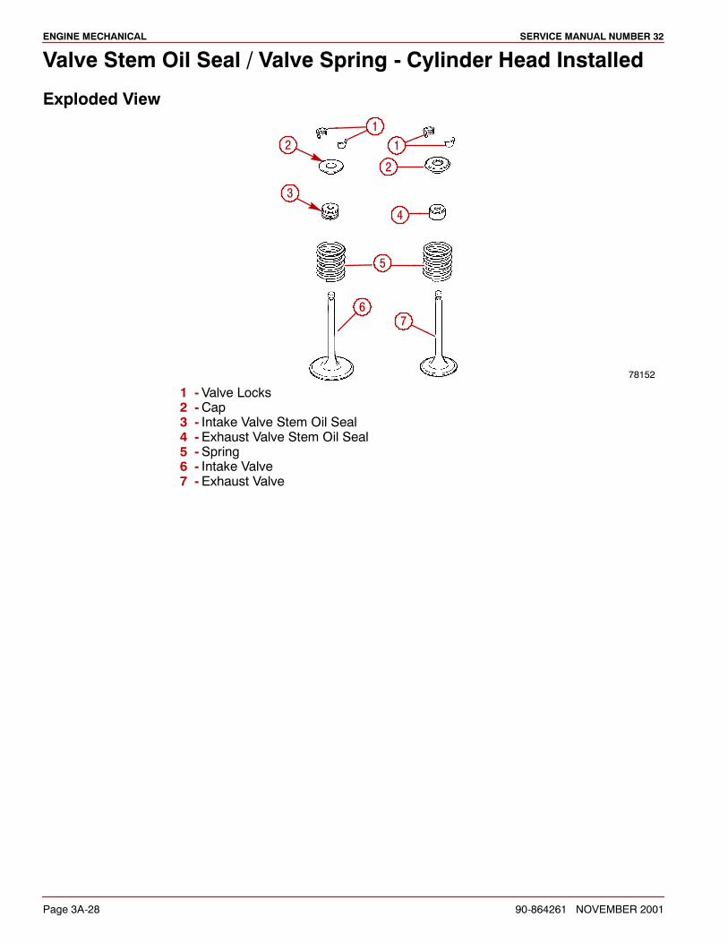
ENGINE MECHANICAL SERVICE MANUAL NUMBER 32
Page 3A-28 90-864261 NOVEMBER 2001
Valve Stem Oil Seal / Valve Spring - Cylinder Head Installed
Exploded View
78152
112
3
2
4
5
67
1 -Valve Locks2 -Cap3 - Intake Valve Stem Oil Seal4 -Exhaust Valve Stem Oil Seal5 -Spring6 - Intake Valve7 -Exhaust Valve
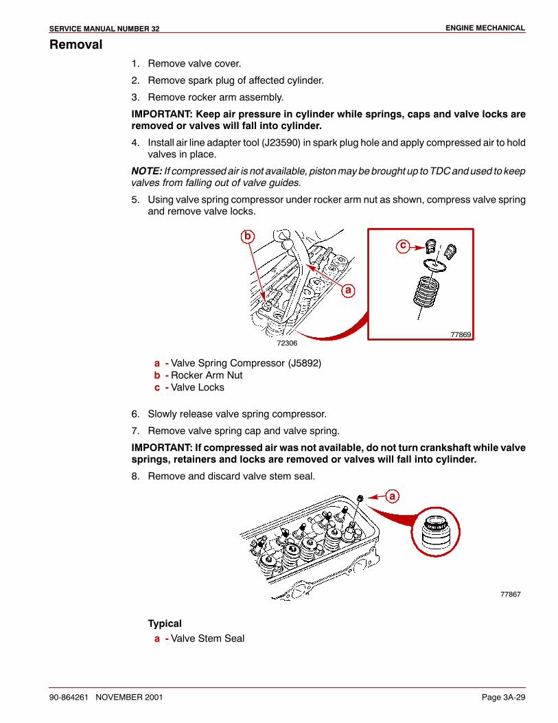
ENGINE MECHANICALSERVICE MANUAL NUMBER 32
90-864261 NOVEMBER 2001 Page 3A-29
Removal1. Remove valve cover.
2. Remove spark plug of affected cylinder.
3. Remove rocker arm assembly.
IMPORTANT: Keep air pressure in cylinder while springs, caps and valve locks areremoved or valves will fall into cylinder.
4. Install air line adapter tool (J23590) in spark plug hole and apply compressed air to holdvalves in place.
NOTE: If compressedair is not available, pistonmaybebrought up toTDCandused to keepvalves from falling out of valve guides.
5. Using valve spring compressor under rocker arm nut as shown, compress valve springand remove valve locks.
7230677869
a
bc
a - Valve Spring Compressor (J5892)b - Rocker Arm Nutc - Valve Locks
6. Slowly release valve spring compressor.
7. Remove valve spring cap and valve spring.
IMPORTANT: If compressed air was not available, do not turn crankshaft while valvesprings, retainers and locks are removed or valves will fall into cylinder.
8. Remove and discard valve stem seal.
77867
a
Typicala - Valve Stem Seal
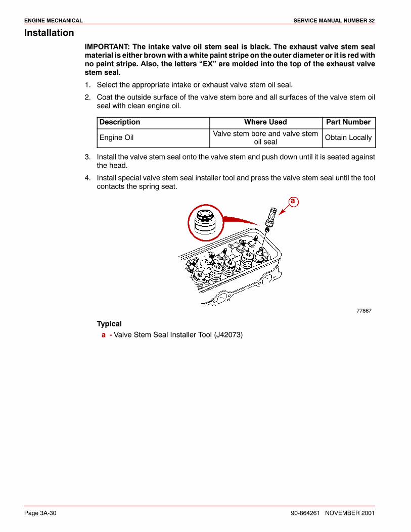
ENGINE MECHANICAL SERVICE MANUAL NUMBER 32
Page 3A-30 90-864261 NOVEMBER 2001
InstallationIMPORTANT: The intake valve oil stem seal is black. The exhaust valve stem sealmaterial is either brownwith awhite paint stripe on theouter diameter or it is redwithno paint stripe. Also, the letters “EX” are molded into the top of the exhaust valvestem seal.
1. Select the appropriate intake or exhaust valve stem oil seal.
2. Coat the outside surface of the valve stem bore and all surfaces of the valve stem oilseal with clean engine oil.
Description Where Used Part Number
Engine Oil Valve stem bore and valve stemoil seal Obtain Locally
3. Install the valve stem seal onto the valve stem and push down until it is seated againstthe head.
4. Install special valve stem seal installer tool and press the valve stem seal until the toolcontacts the spring seat.
a
77867
Typicala - Valve Stem Seal Installer Tool (J42073)
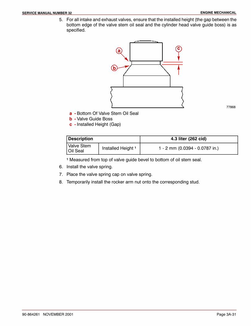
ENGINE MECHANICALSERVICE MANUAL NUMBER 32
90-864261 NOVEMBER 2001 Page 3A-31
5. For all intake and exhaust valves, ensure that the installed height (the gap between thebottom edge of the valve stem oil seal and the cylinder head valve guide boss) is asspecified.
77868
a
b
c
a - Bottom Of Valve Stem Oil Sealb - Valve Guide Bossc - Installed Height (Gap)
Description 4.3 liter (262 cid)
Valve StemOil Seal Installed Height 1 1 - 2 mm (0.0394 - 0.0787 in.)
1 Measured from top of valve guide bevel to bottom of oil stem seal.
6. Install the valve spring.
7. Place the valve spring cap on valve spring.
8. Temporarily install the rocker arm nut onto the corresponding stud.
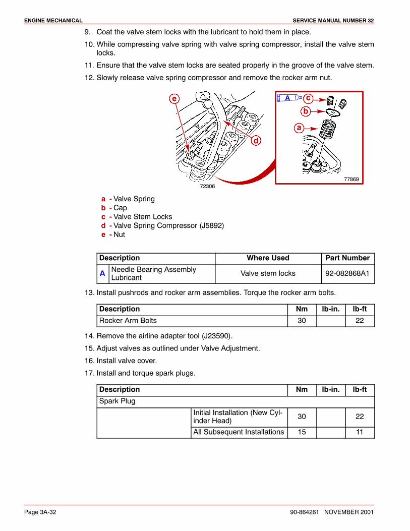
ENGINE MECHANICAL SERVICE MANUAL NUMBER 32
Page 3A-32 90-864261 NOVEMBER 2001
9. Coat the valve stem locks with the lubricant to hold them in place.
10. While compressing valve spring with valve spring compressor, install the valve stemlocks.
11. Ensure that the valve stem locks are seated properly in the groove of the valve stem.
12. Slowly release valve spring compressor and remove the rocker arm nut.
7230677869
a
b
c
d
e A
a - Valve Springb - Capc - Valve Stem Locksd - Valve Spring Compressor (J5892)e - Nut
Description Where Used Part Number
A Needle Bearing AssemblyLubricant Valve stem locks 92-082868A1
13. Install pushrods and rocker arm assemblies. Torque the rocker arm bolts.
Description Nm lb-in. lb-ft
Rocker Arm Bolts 30 22
14. Remove the airline adapter tool (J23590).
15. Adjust valves as outlined under Valve Adjustment.
16. Install valve cover.
17. Install and torque spark plugs.
Description Nm lb-in. lb-ft
Spark Plug
Initial Installation (New Cyl-inder Head) 30 22
All Subsequent Installations 15 11
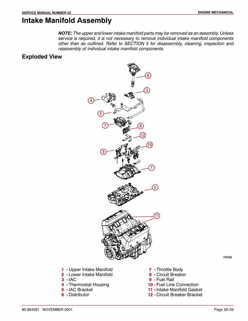
ENGINE MECHANICALSERVICE MANUAL NUMBER 32
90-864261 NOVEMBER 2001 Page 3A-33
Intake Manifold Assembly
NOTE: The upper and lower intakemanifold partsmay be removed as an assembly. Unlessservice is required, it is not necessary to remove individual intake manifold componentsother than as outlined. Refer to SECTION 5 for disassembly, cleaning, inspection andreassembly of individual intake manifold components.
Exploded View
78088
1
2
6
9
4
11
10
3
5
7 8
12
1 -Upper Intake Manifold2 - Lower Intake Manifold3 - IAC4 - Thermostat Housing5 - IAC Bracket6 -Distributor
7 - Throttle Body8 -Circuit Breaker9 - Fuel Rail10 - Fuel Line Connection11 - Intake Manifold Gasket12 -Circuit Breaker Bracket
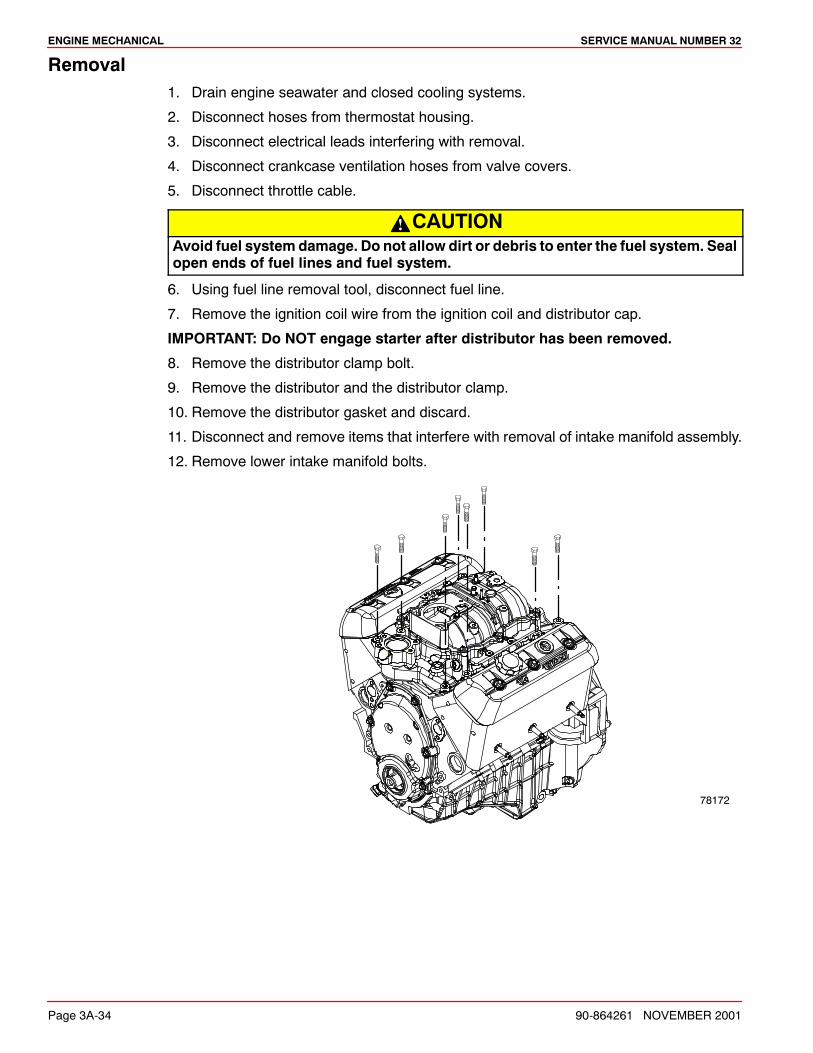
ENGINE MECHANICAL SERVICE MANUAL NUMBER 32
Page 3A-34 90-864261 NOVEMBER 2001
Removal1. Drain engine seawater and closed cooling systems.
2. Disconnect hoses from thermostat housing.
3. Disconnect electrical leads interfering with removal.
4. Disconnect crankcase ventilation hoses from valve covers.
5. Disconnect throttle cable.
CAUTIONAvoid fuel system damage. Do not allow dirt or debris to enter the fuel system. Sealopen ends of fuel lines and fuel system.
6. Using fuel line removal tool, disconnect fuel line.
7. Remove the ignition coil wire from the ignition coil and distributor cap.
IMPORTANT: Do NOT engage starter after distributor has been removed.
8. Remove the distributor clamp bolt.
9. Remove the distributor and the distributor clamp.
10. Remove the distributor gasket and discard.
11. Disconnect and remove items that interfere with removal of intake manifold assembly.
12. Remove lower intake manifold bolts.
78172
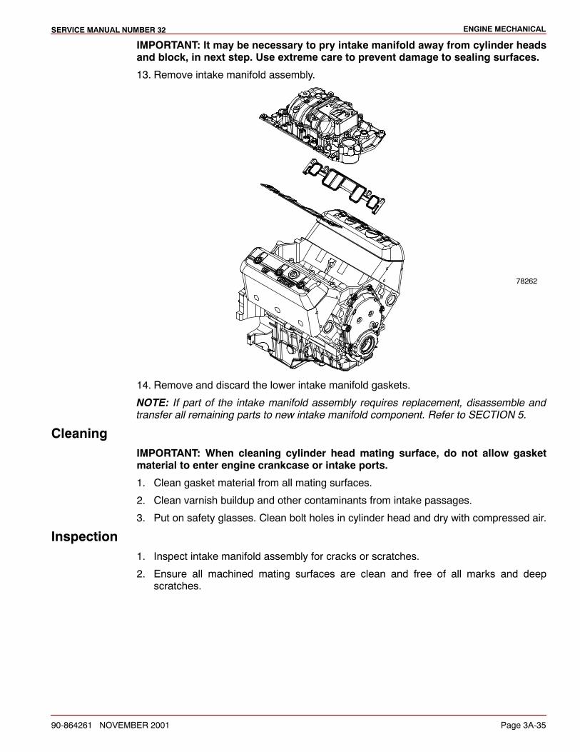
ENGINE MECHANICALSERVICE MANUAL NUMBER 32
90-864261 NOVEMBER 2001 Page 3A-35
IMPORTANT: It may be necessary to pry intake manifold away from cylinder headsand block, in next step. Use extreme care to prevent damage to sealing surfaces.
13. Remove intake manifold assembly.
78262
14. Remove and discard the lower intake manifold gaskets.
NOTE: If part of the intake manifold assembly requires replacement, disassemble andtransfer all remaining parts to new intake manifold component. Refer to SECTION 5.
CleaningIMPORTANT: When cleaning cylinder head mating surface, do not allow gasketmaterial to enter engine crankcase or intake ports.
1. Clean gasket material from all mating surfaces.
2. Clean varnish buildup and other contaminants from intake passages.
3. Put on safety glasses. Clean bolt holes in cylinder head and dry with compressed air.
Inspection1. Inspect intake manifold assembly for cracks or scratches.
2. Ensure all machined mating surfaces are clean and free of all marks and deepscratches.
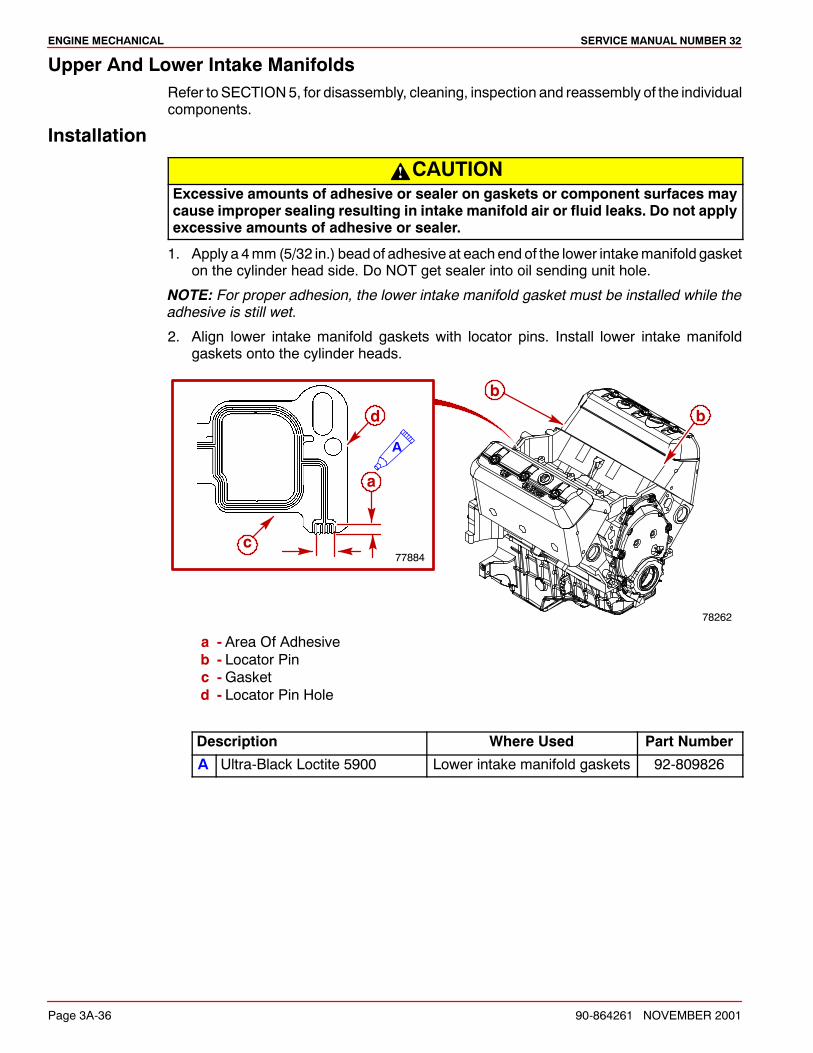
ENGINE MECHANICAL SERVICE MANUAL NUMBER 32
Page 3A-36 90-864261 NOVEMBER 2001
Upper And Lower Intake ManifoldsRefer to SECTION5, for disassembly, cleaning, inspection and reassembly of the individualcomponents.
Installation
CAUTIONExcessive amounts of adhesive or sealer on gaskets or component surfaces maycause improper sealing resulting in intake manifold air or fluid leaks. Do not applyexcessive amounts of adhesive or sealer.
1. Apply a 4mm (5/32 in.) beadof adhesive at eachend of the lower intakemanifold gasketon the cylinder head side. Do NOT get sealer into oil sending unit hole.
NOTE: For proper adhesion, the lower intake manifold gasket must be installed while theadhesive is still wet.
2. Align lower intake manifold gaskets with locator pins. Install lower intake manifoldgaskets onto the cylinder heads.
77884
a
b
b
c
d
78262
A
a - Area Of Adhesiveb - Locator Pinc -Gasketd - Locator Pin Hole
Description Where Used Part Number
A Ultra-Black Loctite 5900 Lower intake manifold gaskets 92-809826
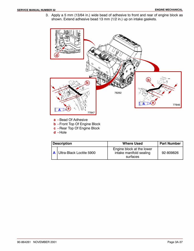
ENGINE MECHANICALSERVICE MANUAL NUMBER 32
90-864261 NOVEMBER 2001 Page 3A-37
3. Apply a 5 mm (13/64 in.) wide bead of adhesive to front and rear of engine block asshown. Extend adhesive bead 13 mm (1/2 in.) up on intake gaskets.
78262
77847A
d
a
b
77846
b
aA
a - Bead Of Adhesiveb - Front Top Of Engine Blockc - Rear Top Of Engine Blockd - Hole
Description Where Used Part Number
A Ultra-Black Loctite 5900Engine block at the lowerintake manifold sealing
surfaces92-809826
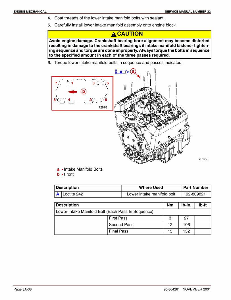
ENGINE MECHANICAL SERVICE MANUAL NUMBER 32
Page 3A-38 90-864261 NOVEMBER 2001
4. Coat threads of the lower intake manifold bolts with sealant.
5. Carefully install lower intake manifold assembly onto engine block.
CAUTIONAvoid engine damage. Crankshaft bearing bore alignment may become distortedresulting in damage to the crankshaft bearings if intake manifold fastener tighten-ing sequence and torque are done improperly. Always torque the bolts in sequenceto the specified amount in each of the three passes required.
6. Torque lower intake manifold bolts in sequence and passes indicated.
72878
1
2
3
4
5
6
7
8
A a
78172
b
a - Intake Manifold Boltsb - Front
Description Where Used Part Number
A Loctite 242 Lower intake manifold bolt 92-809821
Description Nm lb-in. lb-ft
Lower Intake Manifold Bolt (Each Pass In Sequence)
First Pass 3 27
Second Pass 12 106
Final Pass 15 132
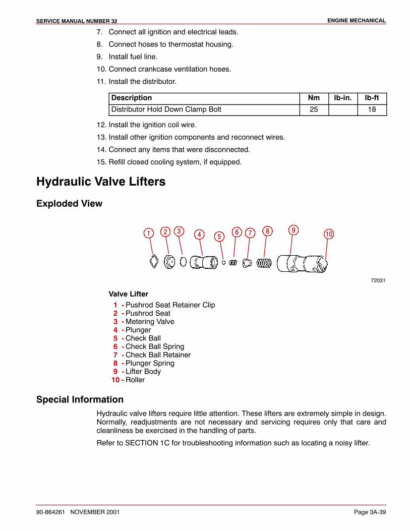
ENGINE MECHANICALSERVICE MANUAL NUMBER 32
90-864261 NOVEMBER 2001 Page 3A-39
7. Connect all ignition and electrical leads.
8. Connect hoses to thermostat housing.
9. Install fuel line.
10. Connect crankcase ventilation hoses.
11. Install the distributor.
Description Nm lb-in. lb-ft
Distributor Hold Down Clamp Bolt 25 18
12. Install the ignition coil wire.
13. Install other ignition components and reconnect wires.
14. Connect any items that were disconnected.
15. Refill closed cooling system, if equipped.
Hydraulic Valve Lifters
Exploded View
72031
1 2 3 4 5 6 7 8 9 10
Valve Lifter1 -Pushrod Seat Retainer Clip2 -Pushrod Seat3 -Metering Valve4 -Plunger5 -Check Ball6 -Check Ball Spring7 -Check Ball Retainer8 -Plunger Spring9 - Lifter Body10 -Roller
Special InformationHydraulic valve lifters require little attention. These lifters are extremely simple in design.Normally, readjustments are not necessary and servicing requires only that care andcleanliness be exercised in the handling of parts.
Refer to SECTION 1C for troubleshooting information such as locating a noisy lifter.
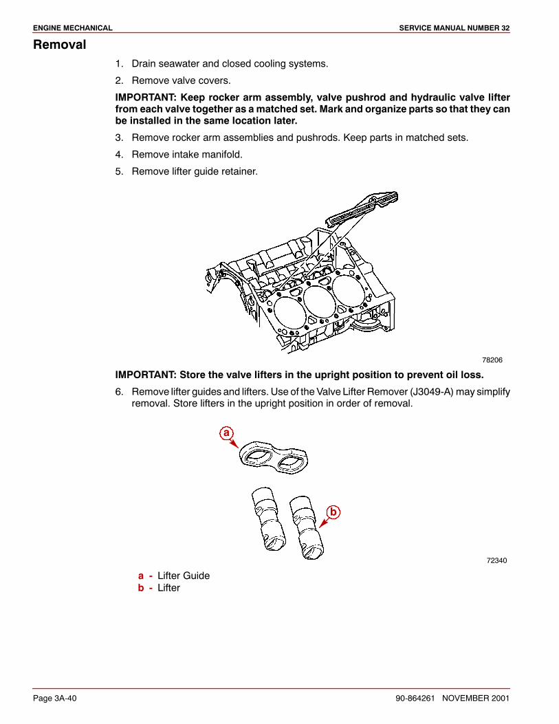
ENGINE MECHANICAL SERVICE MANUAL NUMBER 32
Page 3A-40 90-864261 NOVEMBER 2001
Removal1. Drain seawater and closed cooling systems.
2. Remove valve covers.
IMPORTANT: Keep rocker arm assembly, valve pushrod and hydraulic valve lifterfrom each valve together as a matched set. Mark and organize parts so that they canbe installed in the same location later.
3. Remove rocker arm assemblies and pushrods. Keep parts in matched sets.
4. Remove intake manifold.
5. Remove lifter guide retainer.
78206
IMPORTANT: Store the valve lifters in the upright position to prevent oil loss.
6. Remove lifter guides and lifters. Use of the Valve Lifter Remover (J3049-A)may simplifyremoval. Store lifters in the upright position in order of removal.
72340
a
b
a - Lifter Guideb - Lifter
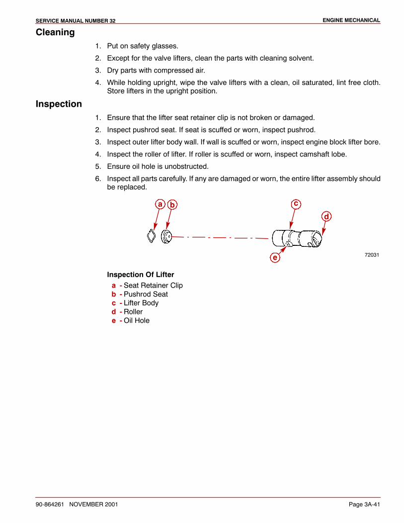
ENGINE MECHANICALSERVICE MANUAL NUMBER 32
90-864261 NOVEMBER 2001 Page 3A-41
Cleaning1. Put on safety glasses.
2. Except for the valve lifters, clean the parts with cleaning solvent.
3. Dry parts with compressed air.
4. While holding upright, wipe the valve lifters with a clean, oil saturated, lint free cloth.Store lifters in the upright position.
Inspection1. Ensure that the lifter seat retainer clip is not broken or damaged.
2. Inspect pushrod seat. If seat is scuffed or worn, inspect pushrod.
3. Inspect outer lifter body wall. If wall is scuffed or worn, inspect engine block lifter bore.
4. Inspect the roller of lifter. If roller is scuffed or worn, inspect camshaft lobe.
5. Ensure oil hole is unobstructed.
6. Inspect all parts carefully. If any are damaged or worn, the entire lifter assembly shouldbe replaced.
72031
a b c
d
e
Inspection Of Liftera - Seat Retainer Clipb - Pushrod Seatc - Lifter Bodyd - Rollere -Oil Hole
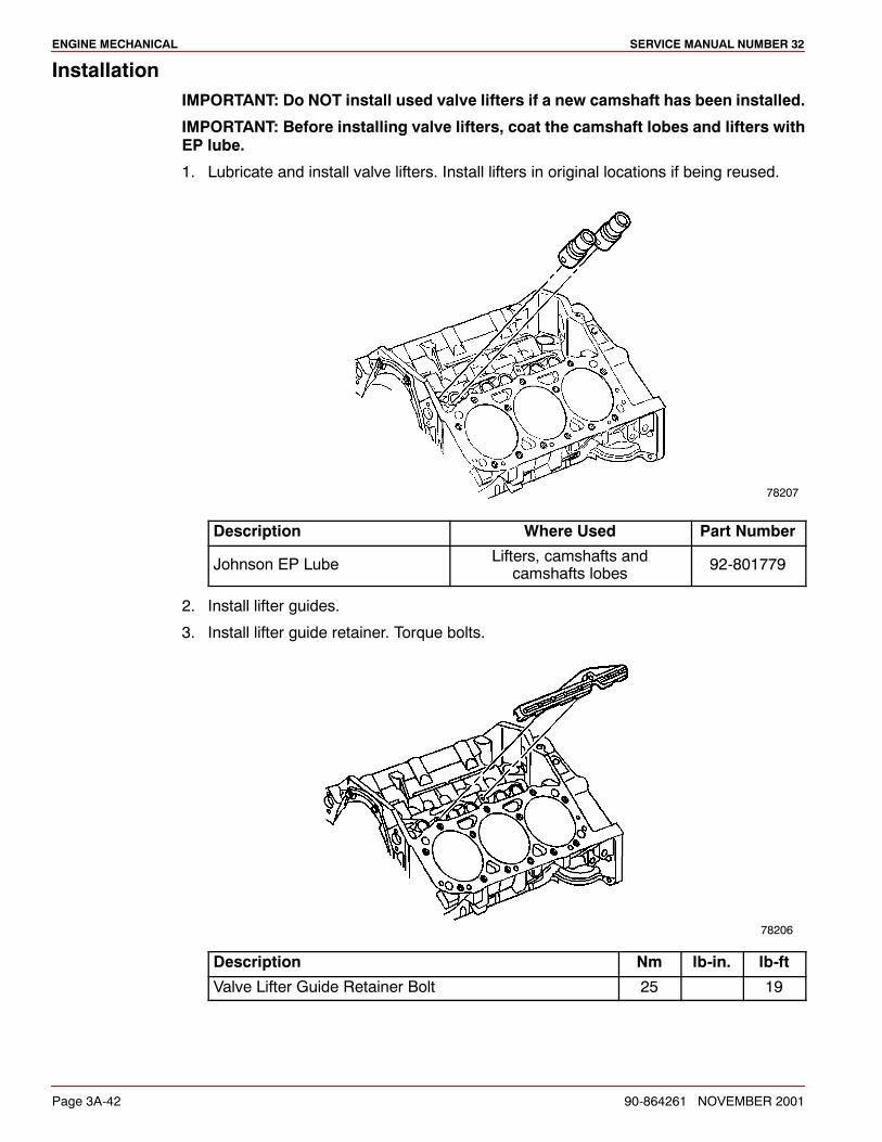
ENGINE MECHANICAL SERVICE MANUAL NUMBER 32
Page 3A-42 90-864261 NOVEMBER 2001
InstallationIMPORTANT: Do NOT install used valve lifters if a new camshaft has been installed.
IMPORTANT: Before installing valve lifters, coat the camshaft lobes and lifters withEP lube.
1. Lubricate and install valve lifters. Install lifters in original locations if being reused.
78207
Description Where Used Part Number
Johnson EP Lube Lifters, camshafts andcamshafts lobes 92-801779
2. Install lifter guides.
3. Install lifter guide retainer. Torque bolts.
78206
Description Nm lb-in. lb-ft
Valve Lifter Guide Retainer Bolt 25 19
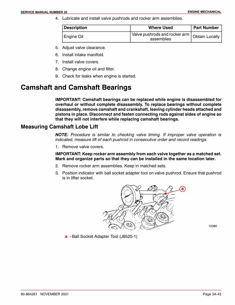
ENGINE MECHANICALSERVICE MANUAL NUMBER 32
90-864261 NOVEMBER 2001 Page 3A-43
4. Lubricate and install valve pushrods and rocker arm assemblies.
Description Where Used Part Number
Engine Oil Valve pushrods and rocker armassemblies Obtain Locally
5. Adjust valve clearance.
6. Install intake manifold.
7. Install valve covers.
8. Change engine oil and filter.
9. Check for leaks when engine is started.
Camshaft and Camshaft Bearings
IMPORTANT: Camshaft bearings can be replaced while engine is disassembled foroverhaul or without complete disassembly. To replace bearings without completedisassembly, remove camshaft and crankshaft, leaving cylinder heads attached andpistons in place. Disconnect and fasten connecting rods against sides of engine sothat they will not interfere while replacing camshaft bearings.
Measuring Camshaft Lobe LiftNOTE: Procedure is similar to checking valve timing. If improper valve operation isindicated, measure lift of each pushrod in consecutive order and record readings.
1. Remove valve covers.
IMPORTANT: Keep rocker arm assembly from each valve together as a matched set.Mark and organize parts so that they can be installed in the same location later.
2. Remove rocker arm assemblies. Keep in matched sets.
3. Position indicator with ball socket adapter tool on valve pushrod. Ensure that pushrodis in lifter socket.
72380
a
a - Ball Socket Adapter Tool (J8520-1)
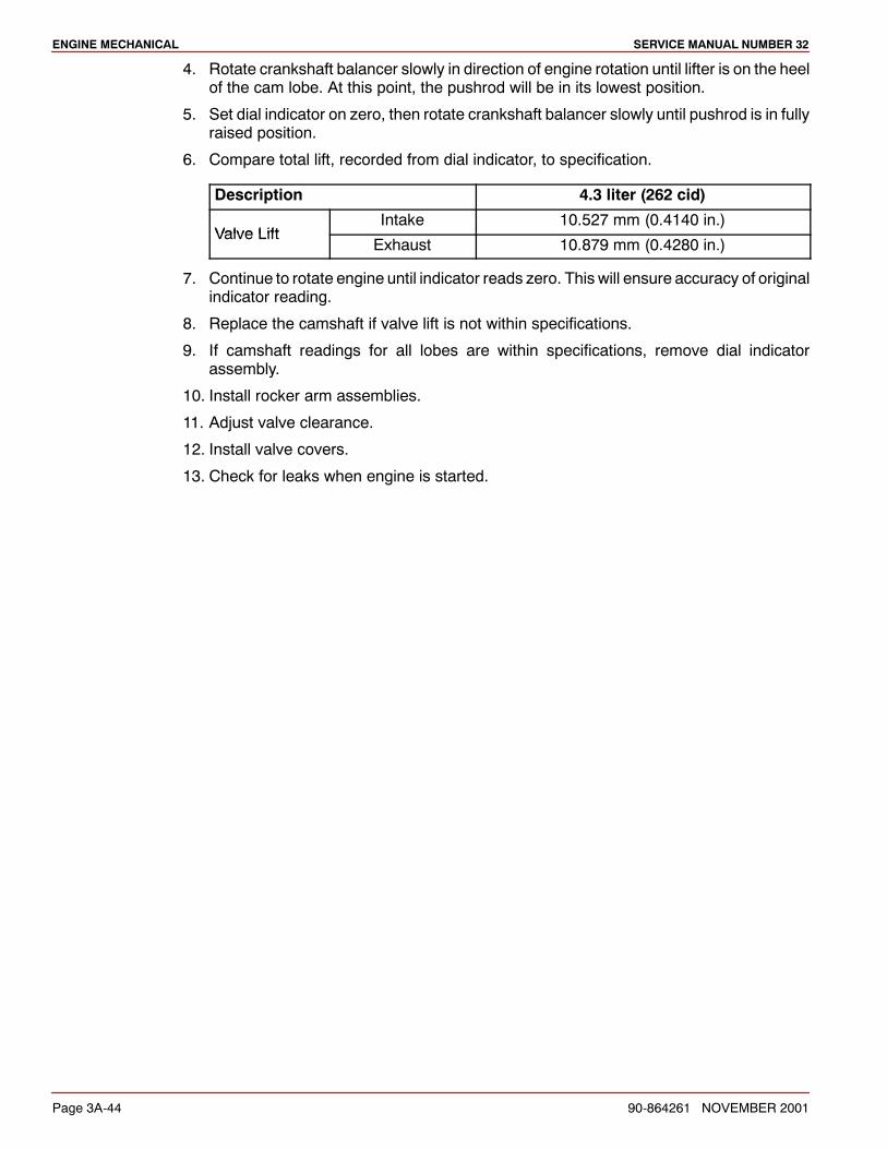
ENGINE MECHANICAL SERVICE MANUAL NUMBER 32
Page 3A-44 90-864261 NOVEMBER 2001
4. Rotate crankshaft balancer slowly in direction of engine rotation until lifter is on the heelof the cam lobe. At this point, the pushrod will be in its lowest position.
5. Set dial indicator on zero, then rotate crankshaft balancer slowly until pushrod is in fullyraised position.
6. Compare total lift, recorded from dial indicator, to specification.
Description 4.3 liter (262 cid)
Valve LiftIntake 10.527 mm (0.4140 in.)
Valve LiftExhaust 10.879 mm (0.4280 in.)
7. Continue to rotate engine until indicator reads zero. This will ensure accuracy of originalindicator reading.
8. Replace the camshaft if valve lift is not within specifications.
9. If camshaft readings for all lobes are within specifications, remove dial indicatorassembly.
10. Install rocker arm assemblies.
11. Adjust valve clearance.
12. Install valve covers.
13. Check for leaks when engine is started.
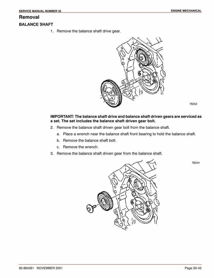
ENGINE MECHANICALSERVICE MANUAL NUMBER 32
90-864261 NOVEMBER 2001 Page 3A-45
RemovalBALANCE SHAFT
1. Remove the balance shaft drive gear.
78252
IMPORTANT: The balance shaft drive and balance shaft driven gears are serviced asa set. The set includes the balance shaft driven gear bolt.
2. Remove the balance shaft driven gear bolt from the balance shaft.
a. Place a wrench near the balance shaft front bearing to hold the balance shaft.
b. Remove the balance shaft bolt.
c. Remove the wrench.
3. Remove the balance shaft driven gear from the balance shaft.
78244
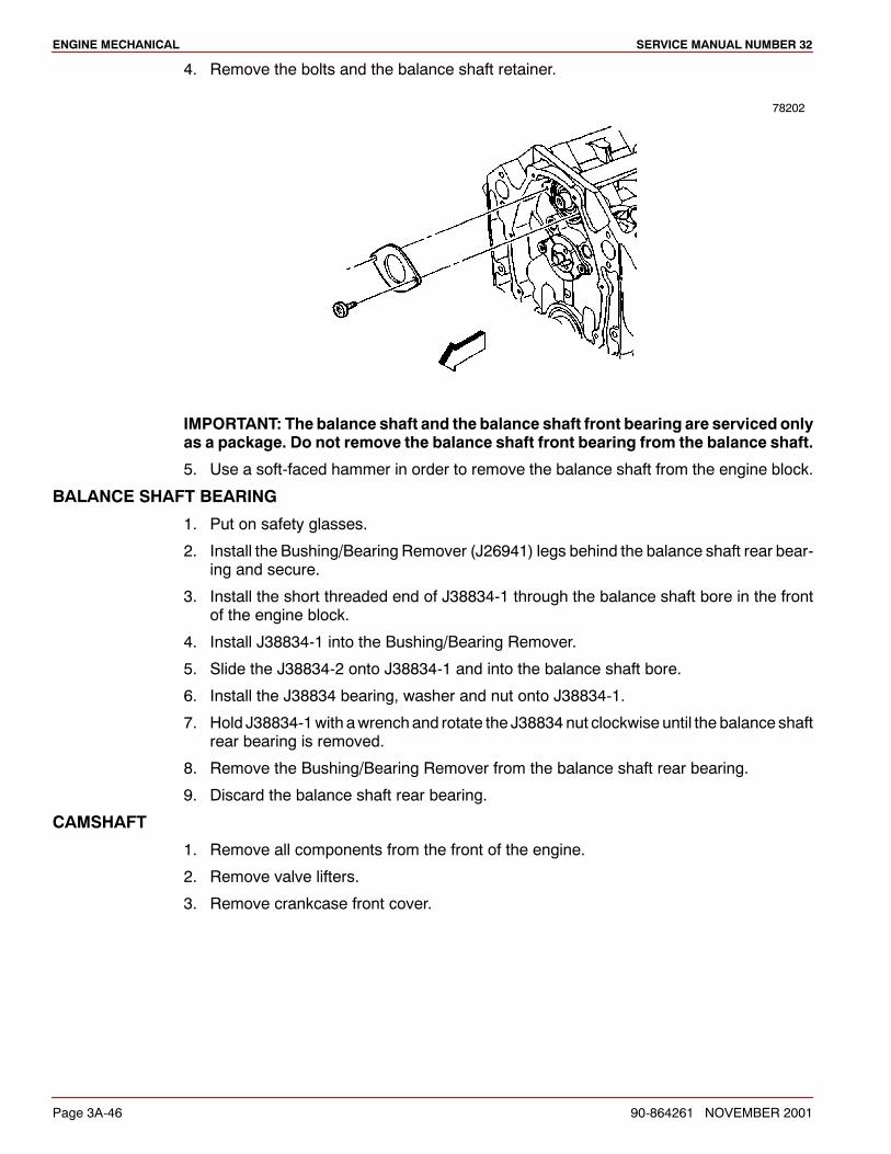
ENGINE MECHANICAL SERVICE MANUAL NUMBER 32
Page 3A-46 90-864261 NOVEMBER 2001
4. Remove the bolts and the balance shaft retainer.
78202
IMPORTANT: The balance shaft and the balance shaft front bearing are serviced onlyas a package. Do not remove the balance shaft front bearing from the balance shaft.
5. Use a soft-faced hammer in order to remove the balance shaft from the engine block.
BALANCE SHAFT BEARING
1. Put on safety glasses.
2. Install the Bushing/Bearing Remover (J26941) legs behind the balance shaft rear bear-ing and secure.
3. Install the short threaded end of J38834-1 through the balance shaft bore in the frontof the engine block.
4. Install J38834-1 into the Bushing/Bearing Remover.
5. Slide the J38834-2 onto J38834-1 and into the balance shaft bore.
6. Install the J38834 bearing, washer and nut onto J38834-1.
7. Hold J38834-1with awrenchand rotate the J38834 nut clockwise until the balance shaftrear bearing is removed.
8. Remove the Bushing/Bearing Remover from the balance shaft rear bearing.
9. Discard the balance shaft rear bearing.
CAMSHAFT
1. Remove all components from the front of the engine.
2. Remove valve lifters.
3. Remove crankcase front cover.
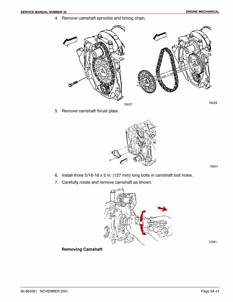
ENGINE MECHANICALSERVICE MANUAL NUMBER 32
90-864261 NOVEMBER 2001 Page 3A-47
4. Remove camshaft sprocket and timing chain.
78227 78228
5. Remove camshaft thrust plate.
78201
6. Install three 5/16-18 x 5 in. (127 mm) long bolts in camshaft bolt holes.
7. Carefully rotate and remove camshaft as shown.
72381
Removing Camshaft
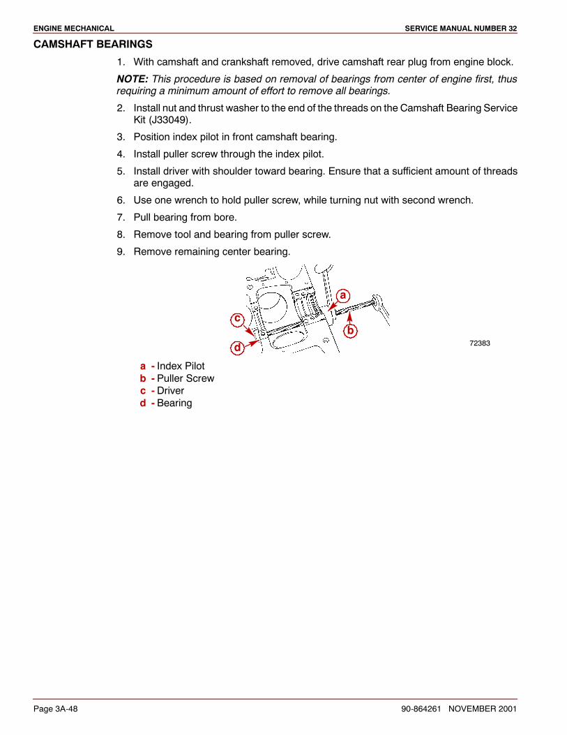
ENGINE MECHANICAL SERVICE MANUAL NUMBER 32
Page 3A-48 90-864261 NOVEMBER 2001
CAMSHAFT BEARINGS
1. With camshaft and crankshaft removed, drive camshaft rear plug from engine block.
NOTE: This procedure is based on removal of bearings from center of engine first, thusrequiring a minimum amount of effort to remove all bearings.
2. Install nut and thrust washer to the end of the threads on the Camshaft Bearing ServiceKit (J33049).
3. Position index pilot in front camshaft bearing.
4. Install puller screw through the index pilot.
5. Install driver with shoulder toward bearing. Ensure that a sufficient amount of threadsare engaged.
6. Use one wrench to hold puller screw, while turning nut with second wrench.
7. Pull bearing from bore.
8. Remove tool and bearing from puller screw.
9. Remove remaining center bearing.
72383d
c
a
b
a - Index Pilotb - Puller Screwc - Driverd - Bearing
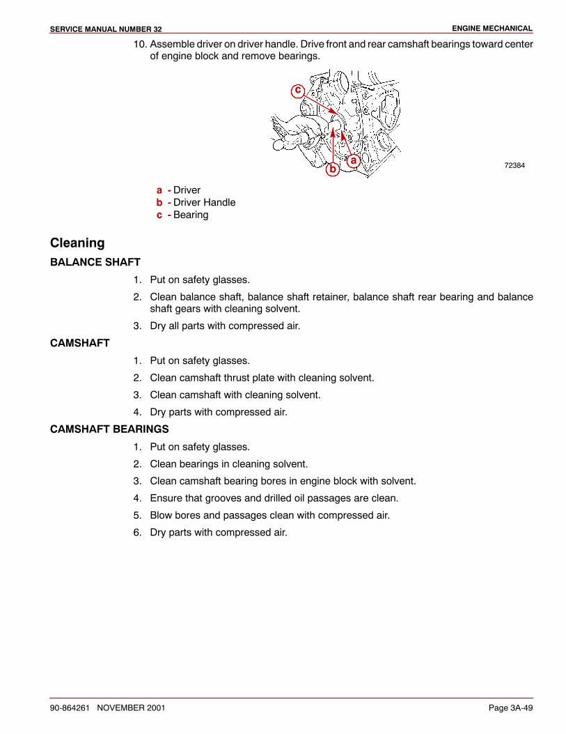
ENGINE MECHANICALSERVICE MANUAL NUMBER 32
90-864261 NOVEMBER 2001 Page 3A-49
10. Assemble driver on driver handle. Drive front and rear camshaft bearings toward centerof engine block and remove bearings.
72384
c
ab
a - Driverb - Driver Handlec - Bearing
CleaningBALANCE SHAFT
1. Put on safety glasses.
2. Clean balance shaft, balance shaft retainer, balance shaft rear bearing and balanceshaft gears with cleaning solvent.
3. Dry all parts with compressed air.
CAMSHAFT
1. Put on safety glasses.
2. Clean camshaft thrust plate with cleaning solvent.
3. Clean camshaft with cleaning solvent.
4. Dry parts with compressed air.
CAMSHAFT BEARINGS
1. Put on safety glasses.
2. Clean bearings in cleaning solvent.
3. Clean camshaft bearing bores in engine block with solvent.
4. Ensure that grooves and drilled oil passages are clean.
5. Blow bores and passages clean with compressed air.
6. Dry parts with compressed air.
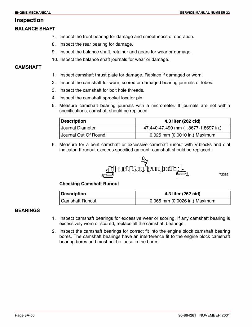
ENGINE MECHANICAL SERVICE MANUAL NUMBER 32
Page 3A-50 90-864261 NOVEMBER 2001
InspectionBALANCE SHAFT
7. Inspect the front bearing for damage and smoothness of operation.
8. Inspect the rear bearing for damage.
9. Inspect the balance shaft, retainer and gears for wear or damage.
10. Inspect the balance shaft journals for wear or damage.
CAMSHAFT
1. Inspect camshaft thrust plate for damage. Replace if damaged or worn.
2. Inspect the camshaft for worn, scored or damaged bearing journals or lobes.
3. Inspect the camshaft for bolt hole threads.
4. Inspect the camshaft sprocket locator pin.
5. Measure camshaft bearing journals with a micrometer. If journals are not withinspecifications, camshaft should be replaced.
Description 4 3 liter (262 cid)Description 4.3 liter (262 cid)Journal Diameter 47.440-47.490 mm (1.8677-1.8697 in.)
Journal Out Of Round 0.025 mm (0.0010 in.) Maximum
6. Measure for a bent camshaft or excessive camshaft runout with V-blocks and dialindicator. If runout exceeds specified amount, camshaft should be replaced.
72382
Checking Camshaft Runout
Description 4.3 liter (262 cid)
Camshaft Runout 0.065 mm (0.0026 in.) Maximum
BEARINGS
1. Inspect camshaft bearings for excessive wear or scoring. If any camshaft bearing isexcessively worn or scored, replace all the camshaft bearings.
2. Inspect the camshaft bearings for correct fit into the engine block camshaft bearingbores. The camshaft bearings have an interference fit to the engine block camshaftbearing bores and must not be loose in the bores.
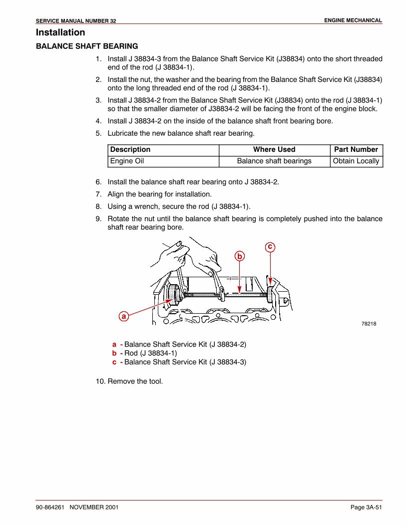
ENGINE MECHANICALSERVICE MANUAL NUMBER 32
90-864261 NOVEMBER 2001 Page 3A-51
InstallationBALANCE SHAFT BEARING
1. Install J 38834-3 from the Balance Shaft Service Kit (J38834) onto the short threadedend of the rod (J 38834-1).
2. Install the nut, the washer and the bearing from the Balance Shaft Service Kit (J38834)onto the long threaded end of the rod (J 38834-1).
3. Install J 38834-2 from the Balance Shaft Service Kit (J38834) onto the rod (J 38834-1)so that the smaller diameter of J38834-2 will be facing the front of the engine block.
4. Install J 38834-2 on the inside of the balance shaft front bearing bore.
5. Lubricate the new balance shaft rear bearing.
Description Where Used Part Number
Engine Oil Balance shaft bearings Obtain Locally
6. Install the balance shaft rear bearing onto J 38834-2.
7. Align the bearing for installation.
8. Using a wrench, secure the rod (J 38834-1).
9. Rotate the nut until the balance shaft bearing is completely pushed into the balanceshaft rear bearing bore.
78218a
bc
a - Balance Shaft Service Kit (J 38834-2)b - Rod (J 38834-1)c - Balance Shaft Service Kit (J 38834-3)
10. Remove the tool.
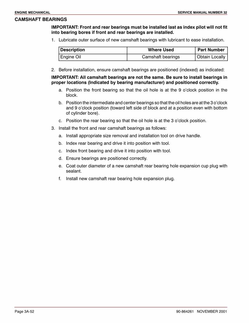
ENGINE MECHANICAL SERVICE MANUAL NUMBER 32
Page 3A-52 90-864261 NOVEMBER 2001
CAMSHAFT BEARINGS
IMPORTANT: Front and rear bearings must be installed last as index pilot will not fitinto bearing bores if front and rear bearings are installed.
1. Lubricate outer surface of new camshaft bearings with lubricant to ease installation.
Description Where Used Part Number
Engine Oil Camshaft bearings Obtain Locally
2. Before installation, ensure camshaft bearings are positioned (indexed) as indicated:
IMPORTANT: All camshaft bearings are not the same. Be sure to install bearings inproper locations (Indicated by bearing manufacturer) and positioned correctly.
a. Position the front bearing so that the oil hole is at the 9 o’clock position in theblock.
b. Position the intermediate and center bearings so that theoil holesare at the 3o’clockand 9 o’clock position (toward left side of block and at a position even with bottomof cylinder bore).
c. Position the rear bearing so that the oil hole is at the 3 o’clock position.
3. Install the front and rear camshaft bearings as follows:
a. Install appropriate size removal and installation tool on drive handle.
b. Index rear bearing and drive it into position with tool.
c. Index front bearing and drive it into position with tool.
d. Ensure bearings are positioned correctly.
e. Coat outer diameter of a new camshaft rear bearing hole expansion cup plug withsealant.
f. Install new camshaft rear bearing hole expansion plug.
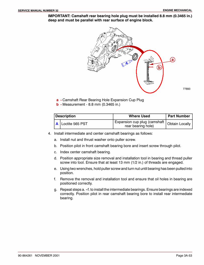
ENGINE MECHANICALSERVICE MANUAL NUMBER 32
90-864261 NOVEMBER 2001 Page 3A-53
IMPORTANT: Camshaft rear bearing hole plug must be installed 8.8 mm (0.3465 in.)deep and must be parallel with rear surface of engine block.
77893
Aa
b
a - Camshaft Rear Bearing Hole Expansion Cup Plugb -Measurement - 8.8 mm (0.3465 in.)
Description Where Used Part Number
A Loctite 565 PST Expansion cup plug (camshaftrear bearing hole) Obtain Locally
4. Install intermediate and center camshaft bearings as follows:
a. Install nut and thrust washer onto puller screw.
b. Position pilot in front camshaft bearing bore and insert screw through pilot.
c. Index center camshaft bearing.
d. Position appropriate size removal and installation tool in bearing and thread pullerscrew into tool. Ensure that at least 13 mm (1/2 in.) of threads are engaged.
e. Using twowrenches, hold puller screwand turn nut until bearing has beenpulled intoposition.
f. Remove the removal and installation tool and ensure that oil holes in bearing arepositioned correctly.
g. Repeat steps a. --f. to install the intermediate bearings. Ensure bearings are indexedcorrectly. Position pilot in rear camshaft bearing bore to install rear intermediatebearing.
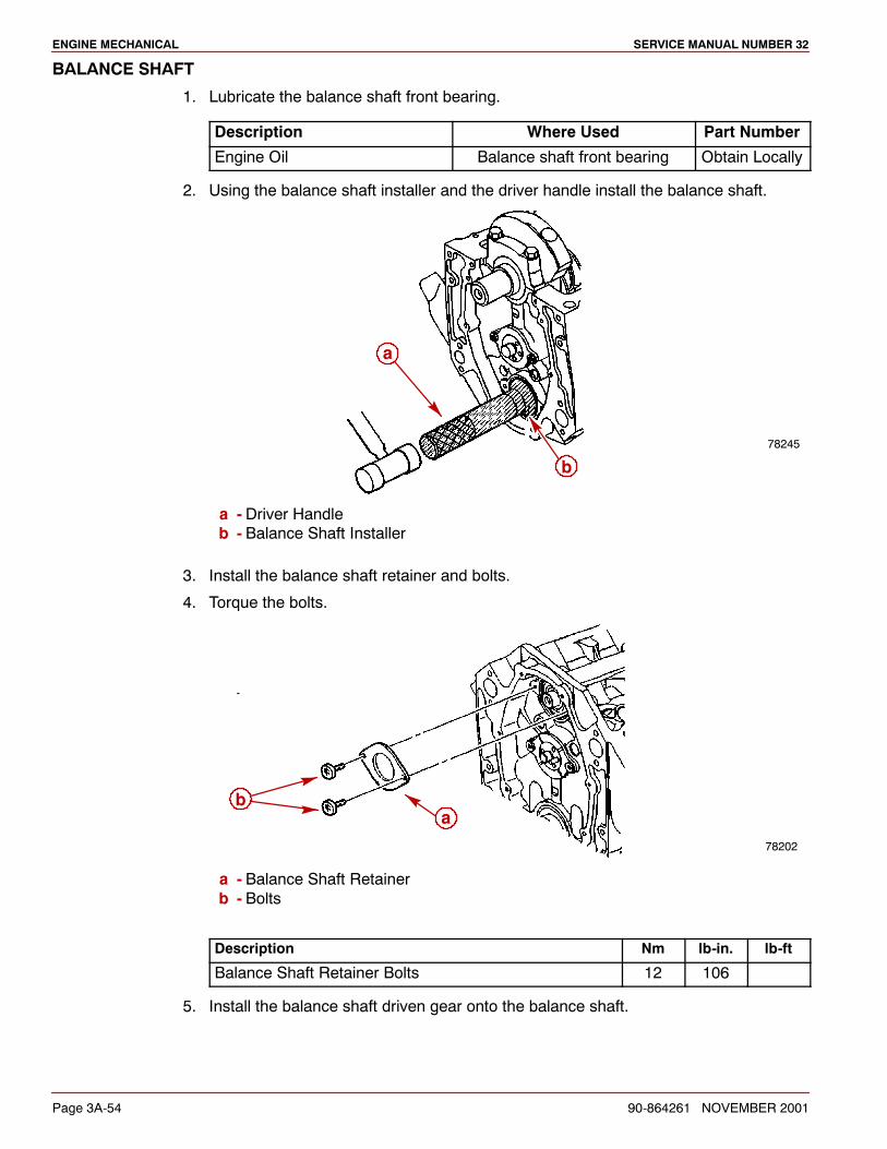
ENGINE MECHANICAL SERVICE MANUAL NUMBER 32
Page 3A-54 90-864261 NOVEMBER 2001
BALANCE SHAFT
1. Lubricate the balance shaft front bearing.
Description Where Used Part Number
Engine Oil Balance shaft front bearing Obtain Locally
2. Using the balance shaft installer and the driver handle install the balance shaft.
78245
a
b
a - Driver Handleb - Balance Shaft Installer
3. Install the balance shaft retainer and bolts.
4. Torque the bolts.
78202
ab
a - Balance Shaft Retainerb - Bolts
Description Nm lb-in. lb-ft
Balance Shaft Retainer Bolts 12 106
5. Install the balance shaft driven gear onto the balance shaft.
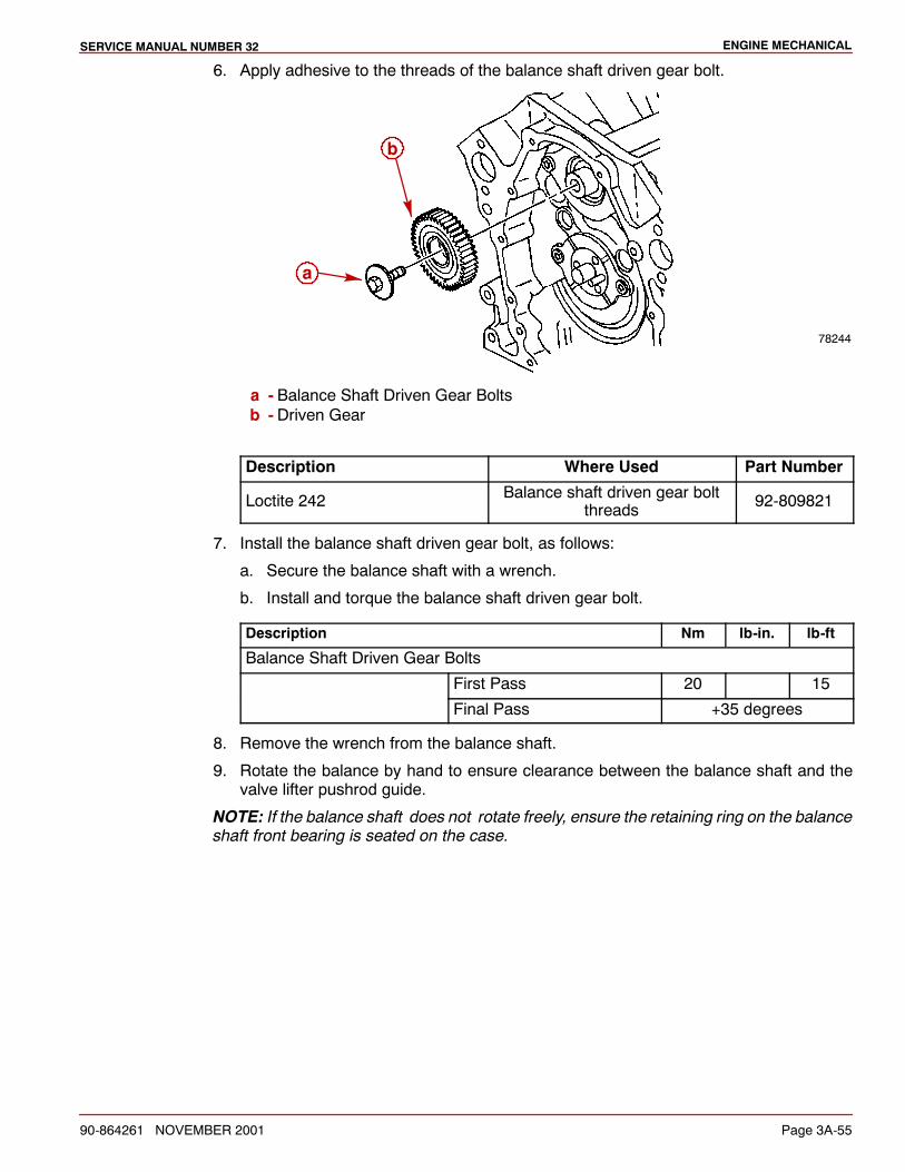
ENGINE MECHANICALSERVICE MANUAL NUMBER 32
90-864261 NOVEMBER 2001 Page 3A-55
6. Apply adhesive to the threads of the balance shaft driven gear bolt.
78244
a
b
a - Balance Shaft Driven Gear Boltsb - Driven Gear
Description Where Used Part Number
Loctite 242 Balance shaft driven gear boltthreads 92-809821
7. Install the balance shaft driven gear bolt, as follows:
a. Secure the balance shaft with a wrench.
b. Install and torque the balance shaft driven gear bolt.
Description Nm lb-in. lb-ft
Balance Shaft Driven Gear Bolts
First Pass 20 15
Final Pass +35 degrees
8. Remove the wrench from the balance shaft.
9. Rotate the balance by hand to ensure clearance between the balance shaft and thevalve lifter pushrod guide.
NOTE: If the balance shaft does not rotate freely, ensure the retaining ring on the balanceshaft front bearing is seated on the case.
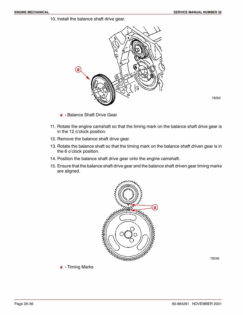
ENGINE MECHANICAL SERVICE MANUAL NUMBER 32
Page 3A-56 90-864261 NOVEMBER 2001
10. Install the balance shaft drive gear.
78252
a
a - Balance Shaft Drive Gear
11. Rotate the engine camshaft so that the timing mark on the balance shaft drive gear isin the 12 o’clock position.
12. Remove the balance shaft drive gear.
13. Rotate the balance shaft so that the timing mark on the balance shaft driven gear is inthe 6 o’clock position.
14. Position the balance shaft drive gear onto the engine camshaft.
15. Ensure that the balance shaft drive gear and the balance shaft driven gear timingmarksare aligned.
78246
a
a - Timing Marks
ENGINE MECHANICALSERVICE MANUAL NUMBER 32
90-864261 NOVEMBER 2001 Page 3A-57
CAMSHAFT
1. Install three 5/16-18 x 5 in. bolts in camshaft bolt holes.
2. Lubricate camshaft journals with engine oil and install camshaft. Be careful not todamage bearings.
Description Where Used Part Number
Engine Oil Camshaft journals Obtain Locally
3. Lubricate camshaft lobes with EP lube or equivalent.
Description Where Used Part Number
Johnson EP Lube Camshafts and camshafts lobes 92-801779
4. Remove the three bolts in camshaft bolt holes.
5. Coat threads of camshaft thrust plate retainer bolts with adhesive.
Description Where Used Part Number
Loctite 242 Threadlocker Camshaft thrust plate retainerbolt 92-809821
6. Install camshaft thrust plate retainer and bolts. Torque bolts.
Description Nm lb-in. lb-ft
Camshaft Thrust Plate (Retainer) Bolts 12 106
7. Install timing chain.
8. Install new crankcase front cover and gasket.
9. Install valve lifters.
10. Install rocker arm assemblies.
11. Adjust valve clearance.
12. Install valve covers.
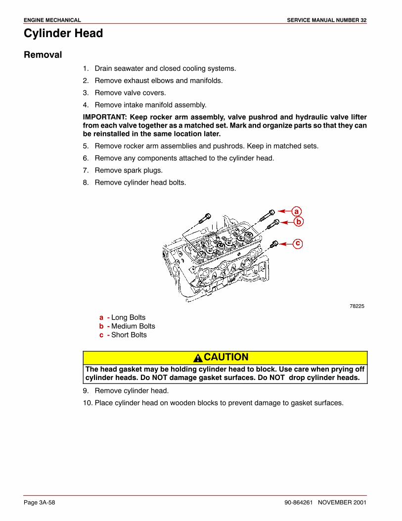
ENGINE MECHANICAL SERVICE MANUAL NUMBER 32
Page 3A-58 90-864261 NOVEMBER 2001
Cylinder Head
Removal1. Drain seawater and closed cooling systems.
2. Remove exhaust elbows and manifolds.
3. Remove valve covers.
4. Remove intake manifold assembly.
IMPORTANT: Keep rocker arm assembly, valve pushrod and hydraulic valve lifterfrom each valve together as a matched set. Mark and organize parts so that they canbe reinstalled in the same location later.
5. Remove rocker arm assemblies and pushrods. Keep in matched sets.
6. Remove any components attached to the cylinder head.
7. Remove spark plugs.
8. Remove cylinder head bolts.
78225
ab
c
a - Long Boltsb -Medium Boltsc - Short Bolts
CAUTIONThe head gasket may be holding cylinder head to block. Use care when prying offcylinder heads. Do NOT damage gasket surfaces. Do NOT drop cylinder heads.
9. Remove cylinder head.
10. Place cylinder head on wooden blocks to prevent damage to gasket surfaces.
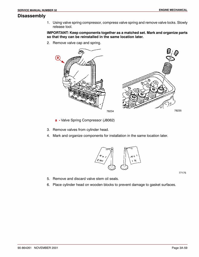
ENGINE MECHANICALSERVICE MANUAL NUMBER 32
90-864261 NOVEMBER 2001 Page 3A-59
Disassembly1. Using valve spring compressor, compress valve spring and remove valve locks. Slowly
release tool.
IMPORTANT: Keep components together as a matched set. Mark and organize partsso that they can be reinstalled in the same location later.
2. Remove valve cap and spring.
78234
a
78235
a - Valve Spring Compressor (J8062)
3. Remove valves from cylinder head.
4. Mark and organize components for installation in the same location later.
77175
5. Remove and discard valve stem oil seals.
6. Place cylinder head on wooden blocks to prevent damage to gasket surfaces.
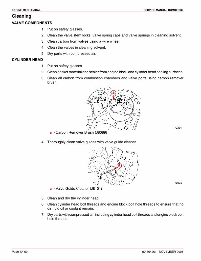
ENGINE MECHANICAL SERVICE MANUAL NUMBER 32
Page 3A-60 90-864261 NOVEMBER 2001
CleaningVALVE COMPONENTS
1. Put on safety glasses.
2. Clean the valve stem locks, valve spring caps and valve springs in cleaning solvent.
3. Clean carbon from valves using a wire wheel.
4. Clean the valves in cleaning solvent.
5. Dry parts with compressed air.
CYLINDER HEAD
1. Put on safety glasses.
2. Clean gasket material and sealer fromengine block and cylinder head sealing surfaces.
3. Clean all carbon from combustion chambers and valve ports using carbon removerbrush.
72334
a
a - Carbon Remover Brush (J8089)
4. Thoroughly clean valve guides with valve guide cleaner.
72335
a
a - Valve Guide Cleaner (J8101)
5. Clean and dry the cylinder head.
6. Clean cylinder head bolt threads and engine block bolt hole threads to ensure that nodirt, old oil or coolant remain.
7. Dry partswith compressedair, including cylinder headbolt threads andengine blockbolthole threads.
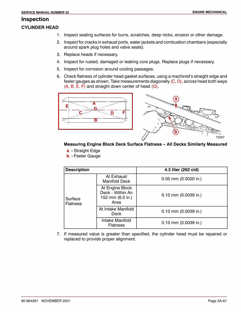
ENGINE MECHANICALSERVICE MANUAL NUMBER 32
90-864261 NOVEMBER 2001 Page 3A-61
InspectionCYLINDER HEAD
1. Inspect sealing surfaces for burrs, scratches, deep nicks, erosion or other damage.
2. Inspect for cracks in exhaust ports, water jackets and combustion chambers (especiallyaround spark plug holes and valve seats).
3. Replace heads if necessary.
4. Inspect for rusted, damaged or leaking core plugs. Replace plugs if necessary.
5. Inspect for corrosion around cooling passages.
6. Check flatness of cylinder head gasket surfaces, using a machinist’s straight edge andfeeler gauges as shown. Takemeasurements diagonally (C, D), across head both ways(A, B, E, F) and straight down center of head (G).
72307
a
b
A
B
C D
EF
G
Measuring Engine Block Deck Surface Flatness -- All Decks Similarly Measureda - Straight Edgeb - Feeler Gauge
Description 4.3 liter (262 cid)
At ExhaustManifold Deck 0.05 mm (0.0020 in.)
SurfaceFlatness
At Engine BlockDeck - Within An152 mm (6.0 in.)
Area
0.10 mm (0.0039 in.)
FlatnessAt Intake Manifold
Deck 0.10 mm (0.0039 in.)
Intake ManifoldFlatness 0.10 mm (0.0039 in.)
7. If measured value is greater than specified, the cylinder head must be repaired orreplaced to provide proper alignment.
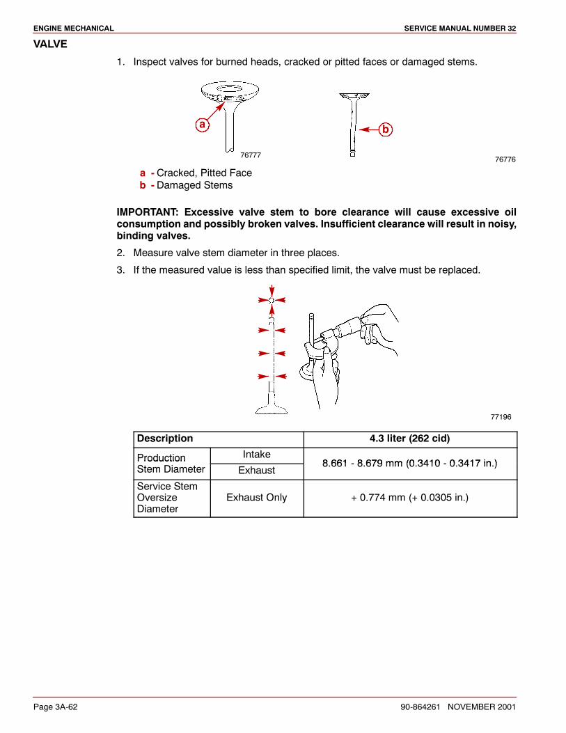
ENGINE MECHANICAL SERVICE MANUAL NUMBER 32
Page 3A-62 90-864261 NOVEMBER 2001
VALVE
1. Inspect valves for burned heads, cracked or pitted faces or damaged stems.
7677676777
a b
a - Cracked, Pitted Faceb - Damaged Stems
IMPORTANT: Excessive valve stem to bore clearance will cause excessive oilconsumption and possibly broken valves. Insufficient clearance will result in noisy,binding valves.
2. Measure valve stem diameter in three places.
3. If the measured value is less than specified limit, the valve must be replaced.
77196
Description 4.3 liter (262 cid)
Production Intake8 661 8 679 mm (0 3410 0 3417 in )Production
Stem Diameter Exhaust8.661 - 8.679 mm (0.3410 - 0.3417 in.)
Service StemOversizeDiameter
Exhaust Only + 0.774 mm (+ 0.0305 in.)
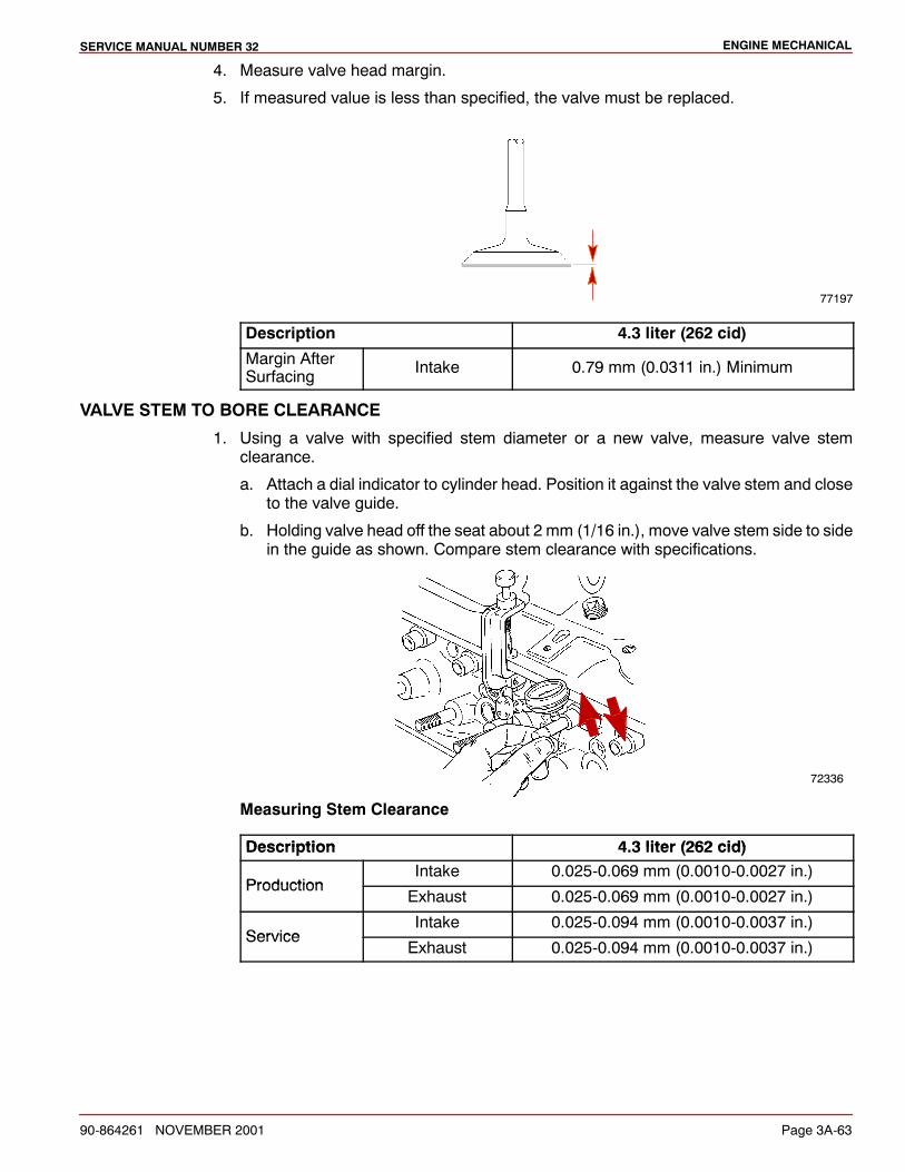
ENGINE MECHANICALSERVICE MANUAL NUMBER 32
90-864261 NOVEMBER 2001 Page 3A-63
4. Measure valve head margin.
5. If measured value is less than specified, the valve must be replaced.
77197
Description 4.3 liter (262 cid)
Margin AfterSurfacing Intake 0.79 mm (0.0311 in.) Minimum
VALVE STEM TO BORE CLEARANCE
1. Using a valve with specified stem diameter or a new valve, measure valve stemclearance.
a. Attach a dial indicator to cylinder head. Position it against the valve stem and closeto the valve guide.
b. Holding valve head off the seat about 2 mm (1/16 in.), move valve stem side to sidein the guide as shown. Compare stem clearance with specifications.
72336
Measuring Stem Clearance
Description 4 3 liter (262 cid)Description 4.3 liter (262 cid)
ProductionIntake 0.025-0.069 mm (0.0010-0.0027 in.)
ProductionExhaust 0.025-0.069 mm (0.0010-0.0027 in.)
ServiceIntake 0.025-0.094 mm (0.0010-0.0037 in.)
ServiceExhaust 0.025-0.094 mm (0.0010-0.0037 in.)
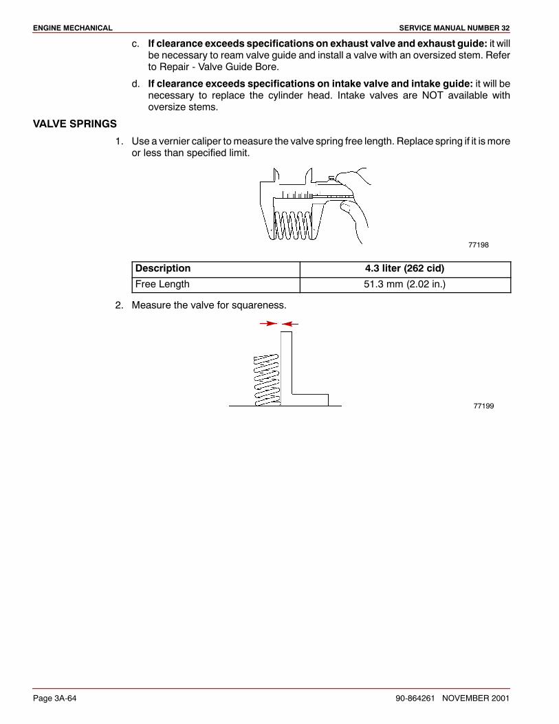
ENGINE MECHANICAL SERVICE MANUAL NUMBER 32
Page 3A-64 90-864261 NOVEMBER 2001
c. If clearance exceeds specifications on exhaust valve and exhaust guide: it willbe necessary to ream valve guide and install a valve with an oversized stem. Referto Repair - Valve Guide Bore.
d. If clearance exceeds specifications on intake valve and intake guide: it will benecessary to replace the cylinder head. Intake valves are NOT available withoversize stems.
VALVE SPRINGS
1. Use a vernier caliper tomeasure the valve spring free length. Replace spring if it ismoreor less than specified limit.
77198
Description 4.3 liter (262 cid)
Free Length 51.3 mm (2.02 in.)
2. Measure the valve for squareness.
77199
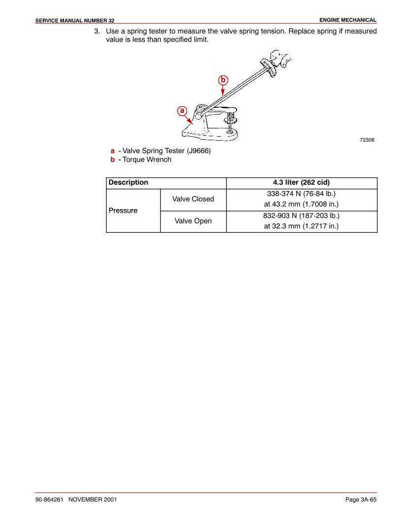
ENGINE MECHANICALSERVICE MANUAL NUMBER 32
90-864261 NOVEMBER 2001 Page 3A-65
3. Use a spring tester to measure the valve spring tension. Replace spring if measuredvalue is less than specified limit.
72308
a
b
a - Valve Spring Tester (J9666)b - Torque Wrench
Description 4.3 liter (262 cid)
Pressure
Valve Closed338-374 N (76-84 lb.)at 43.2 mm (1.7008 in.)
PressureValve Open
832-903 N (187-203 lb.)at 32.3 mm (1.2717 in.)
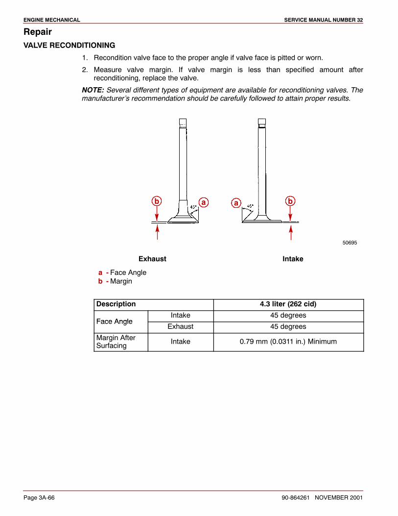
ENGINE MECHANICAL SERVICE MANUAL NUMBER 32
Page 3A-66 90-864261 NOVEMBER 2001
RepairVALVE RECONDITIONING
1. Recondition valve face to the proper angle if valve face is pitted or worn.
2. Measure valve margin. If valve margin is less than specified amount afterreconditioning, replace the valve.
NOTE: Several different types of equipment are available for reconditioning valves. Themanufacturer’s recommendation should be carefully followed to attain proper results.
50695
a ab b
Exhaust Intake
a - Face Angleb -Margin
Description 4.3 liter (262 cid)
Face AngleIntake 45 degrees
Face AngleExhaust 45 degrees
Margin AfterSurfacing Intake 0.79 mm (0.0311 in.) Minimum
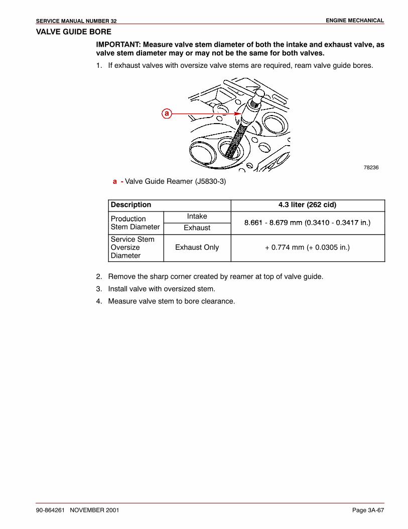
ENGINE MECHANICALSERVICE MANUAL NUMBER 32
90-864261 NOVEMBER 2001 Page 3A-67
VALVE GUIDE BORE
IMPORTANT: Measure valve stem diameter of both the intake and exhaust valve, asvalve stem diameter may or may not be the same for both valves.
1. If exhaust valves with oversize valve stems are required, ream valve guide bores.
78236
a
a - Valve Guide Reamer (J5830-3)
Description 4.3 liter (262 cid)
Production Intake8 661 8 679 mm (0 3410 0 3417 in )Production
Stem Diameter Exhaust8.661 - 8.679 mm (0.3410 - 0.3417 in.)
Service StemOversizeDiameter
Exhaust Only + 0.774 mm (+ 0.0305 in.)
2. Remove the sharp corner created by reamer at top of valve guide.
3. Install valve with oversized stem.
4. Measure valve stem to bore clearance.
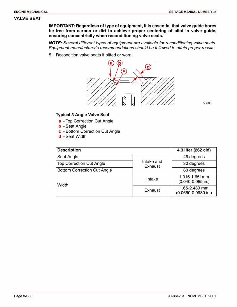
ENGINE MECHANICAL SERVICE MANUAL NUMBER 32
Page 3A-68 90-864261 NOVEMBER 2001
VALVE SEAT
IMPORTANT: Regardless of type of equipment, it is essential that valve guide boresbe free from carbon or dirt to achieve proper centering of pilot in valve guide,ensuring concentricity when reconditioning valve seats.
NOTE: Several different types of equipment are available for reconditioning valve seats.Equipment manufacturer’s recommendations should be followed to attain proper results.
5. Recondition valve seats if pitted or worn.
50668
dc
ba
Typical 3 Angle Valve Seata - Top Correction Cut Angleb - Seat Anglec - Bottom Correction Cut Angled - Seat Width
Description 4.3 liter (262 cid)
Seat AngleI t k d
46 degrees
Top Correction Cut Angle Intake andExhaust
30 degrees
Bottom Correction Cut AngleExhaust
60 degrees
WidthIntake 1.016-1.651mm
(0.040-0.065 in.)Width
Exhaust 1.65-2.489 mm(0.0650-0.0980 in.)
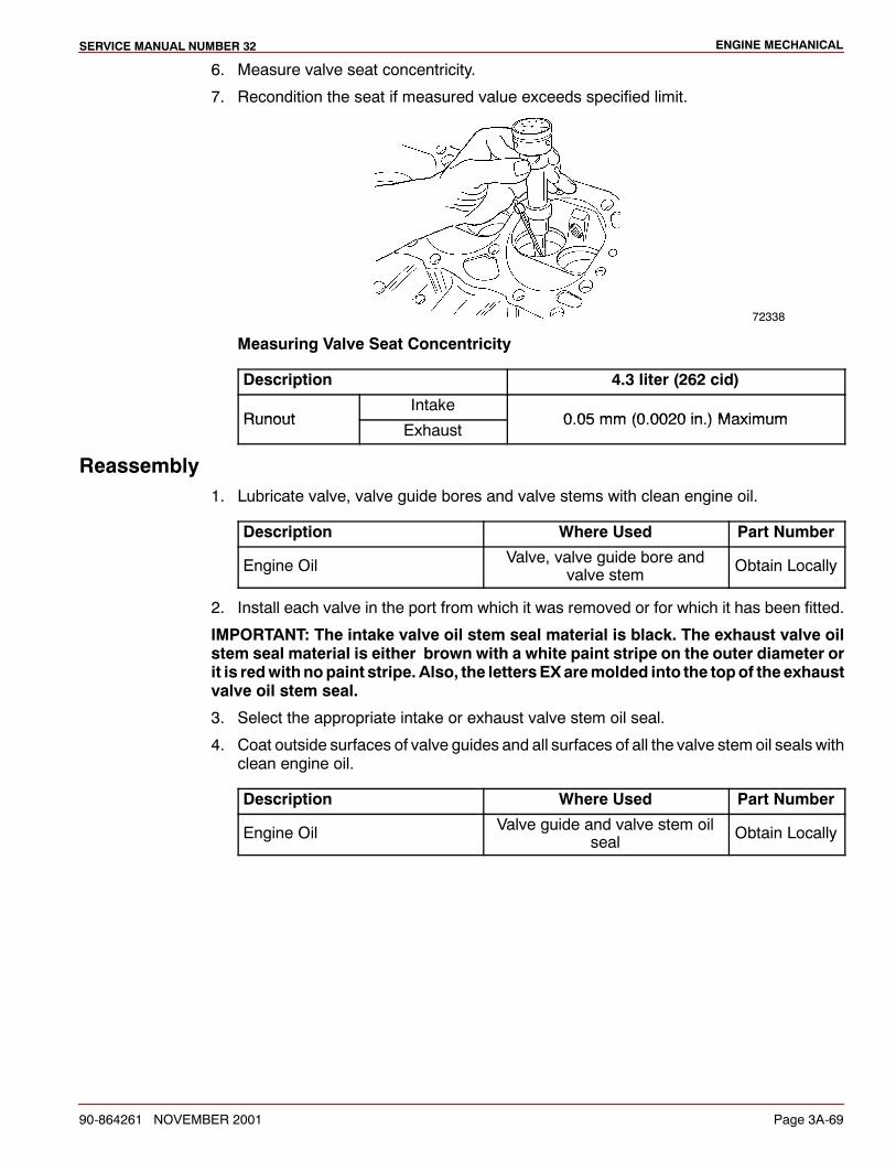
ENGINE MECHANICALSERVICE MANUAL NUMBER 32
90-864261 NOVEMBER 2001 Page 3A-69
6. Measure valve seat concentricity.
7. Recondition the seat if measured value exceeds specified limit.
72338
Measuring Valve Seat Concentricity
Description 4.3 liter (262 cid)
RunoutIntake
0 05 mm (0 0020 in ) MaximumRunoutExhaust
0.05 mm (0.0020 in.) Maximum
Reassembly1. Lubricate valve, valve guide bores and valve stems with clean engine oil.
Description Where Used Part Number
Engine Oil Valve, valve guide bore andvalve stem Obtain Locally
2. Install each valve in the port from which it was removed or for which it has been fitted.
IMPORTANT: The intake valve oil stem seal material is black. The exhaust valve oilstem seal material is either brown with a white paint stripe on the outer diameter orit is redwithnopaint stripe. Also, the lettersEXaremolded into the topof theexhaustvalve oil stem seal.
3. Select the appropriate intake or exhaust valve stem oil seal.
4. Coat outside surfaces of valve guides and all surfaces of all the valve stem oil seals withclean engine oil.
Description Where Used Part Number
Engine Oil Valve guide and valve stem oilseal Obtain Locally
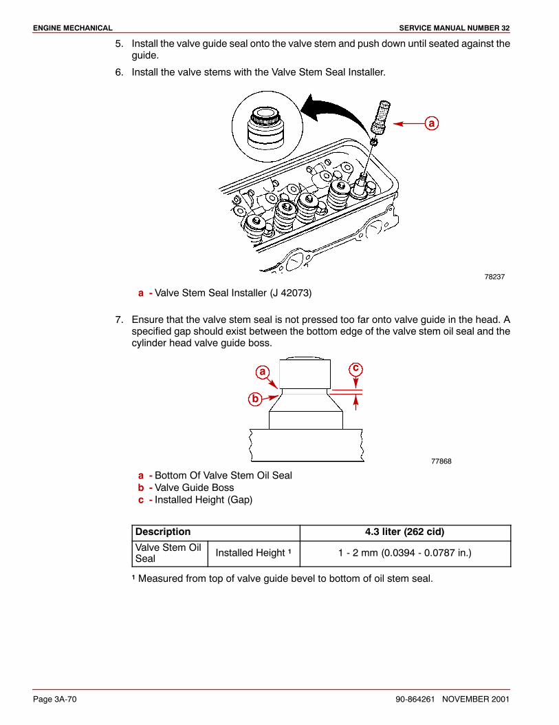
ENGINE MECHANICAL SERVICE MANUAL NUMBER 32
Page 3A-70 90-864261 NOVEMBER 2001
5. Install the valve guide seal onto the valve stem and push down until seated against theguide.
6. Install the valve stems with the Valve Stem Seal Installer.
78237
a
a - Valve Stem Seal Installer (J 42073)
7. Ensure that the valve stem seal is not pressed too far onto valve guide in the head. Aspecified gap should exist between the bottom edge of the valve stem oil seal and thecylinder head valve guide boss.
77868
a
b
c
a - Bottom Of Valve Stem Oil Sealb - Valve Guide Bossc - Installed Height (Gap)
Description 4.3 liter (262 cid)
Valve Stem OilSeal Installed Height 1 1 - 2 mm (0.0394 - 0.0787 in.)
1 Measured from top of valve guide bevel to bottom of oil stem seal.
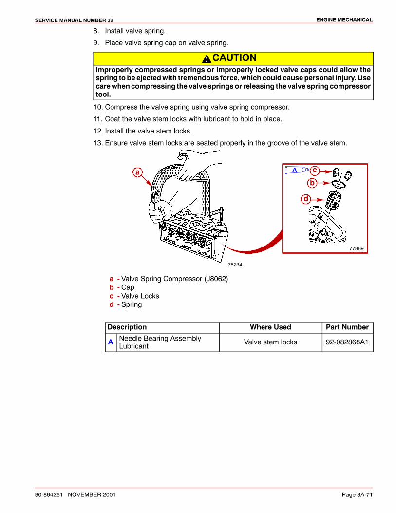
ENGINE MECHANICALSERVICE MANUAL NUMBER 32
90-864261 NOVEMBER 2001 Page 3A-71
8. Install valve spring.
9. Place valve spring cap on valve spring.
CAUTIONImproperly compressed springs or improperly locked valve caps could allow thespring to be ejectedwith tremendous force, which could causepersonal injury. Usecarewhencompressing the valvespringsor releasing thevalve springcompressortool.
10. Compress the valve spring using valve spring compressor.
11. Coat the valve stem locks with lubricant to hold in place.
12. Install the valve stem locks.
13. Ensure valve stem locks are seated properly in the groove of the valve stem.
78234
a
77869
d
b
cA
a - Valve Spring Compressor (J8062)b - Capc - Valve Locksd - Spring
Description Where Used Part Number
A Needle Bearing AssemblyLubricant Valve stem locks 92-082868A1
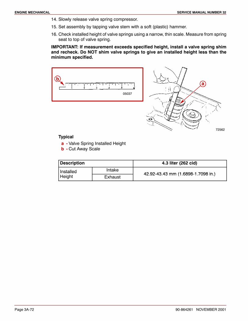
ENGINE MECHANICAL SERVICE MANUAL NUMBER 32
Page 3A-72 90-864261 NOVEMBER 2001
14. Slowly release valve spring compressor.
15. Set assembly by tapping valve stem with a soft (plastic) hammer.
16. Check installed height of valve springs using a narrow, thin scale. Measure from springseat to top of valve spring.
IMPORTANT: If measurement exceeds specified height, install a valve spring shimand recheck. Do NOT shim valve springs to give an installed height less than theminimum specified.
05037
72562
ba
Typicala - Valve Spring Installed Heightb - Cut Away Scale
Description 4.3 liter (262 cid)
Installed Intake42 92 43 43 mm (1 6898 1 7098 in )Installed
Height Exhaust42.92-43.43 mm (1.6898-1.7098 in.)
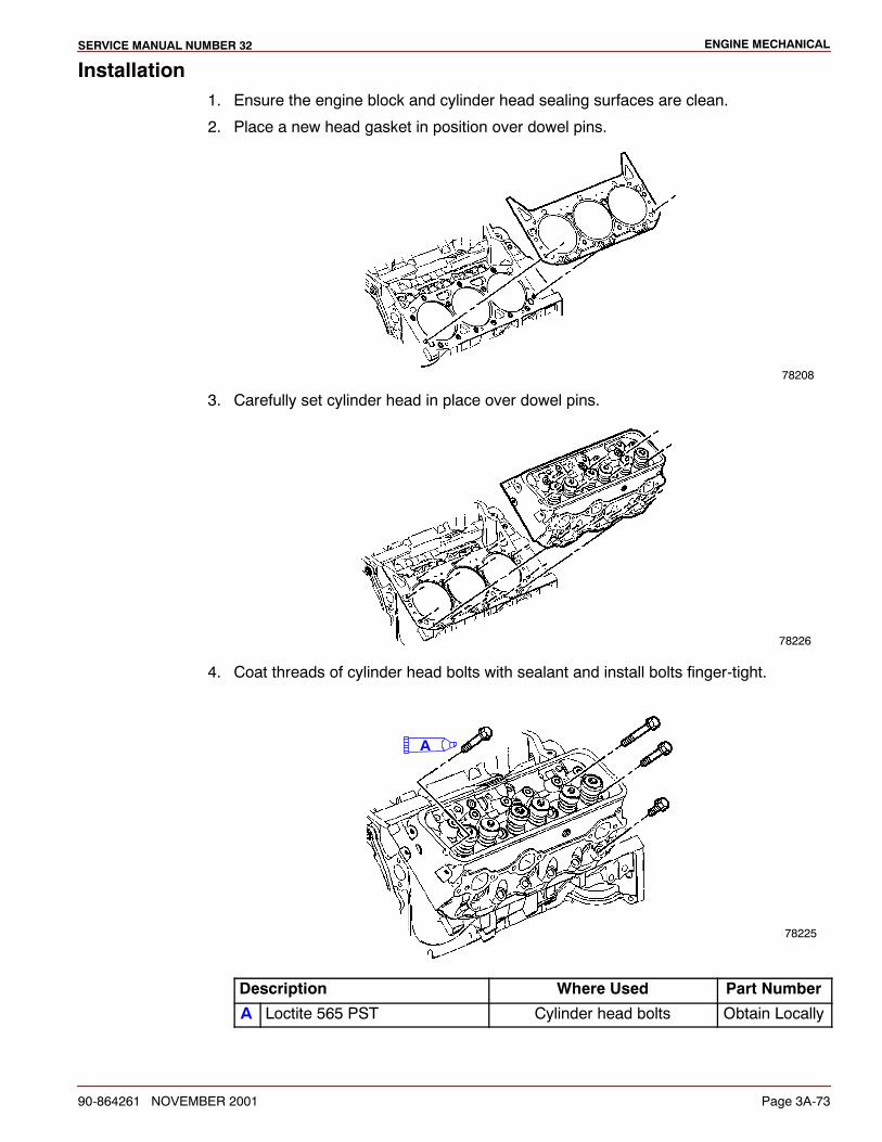
ENGINE MECHANICALSERVICE MANUAL NUMBER 32
90-864261 NOVEMBER 2001 Page 3A-73
Installation1. Ensure the engine block and cylinder head sealing surfaces are clean.
2. Place a new head gasket in position over dowel pins.
78208
3. Carefully set cylinder head in place over dowel pins.
78226
4. Coat threads of cylinder head bolts with sealant and install bolts finger-tight.
78225
A
Description Where Used Part Number
A Loctite 565 PST Cylinder head bolts Obtain Locally
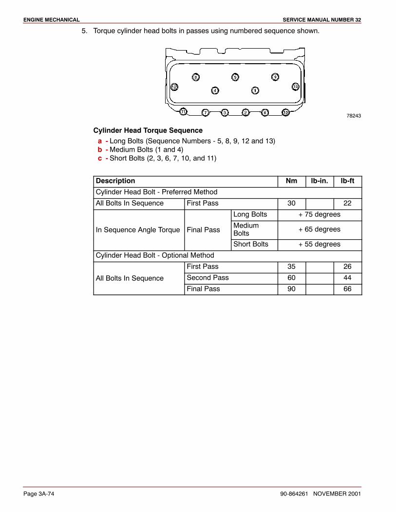
ENGINE MECHANICAL SERVICE MANUAL NUMBER 32
Page 3A-74 90-864261 NOVEMBER 2001
5. Torque cylinder head bolts in passes using numbered sequence shown.
78243
Cylinder Head Torque Sequencea - Long Bolts (Sequence Numbers - 5, 8, 9, 12 and 13)b -Medium Bolts (1 and 4)c - Short Bolts (2, 3, 6, 7, 10, and 11)
Description Nm lb-in. lb-ft
Cylinder Head Bolt - Preferred Method
All Bolts In Sequence First Pass 30 22
Long Bolts + 75 degrees
In Sequence Angle Torque Final PassMediumBolts + 65 degrees
Short Bolts + 55 degrees
Cylinder Head Bolt - Optional Method
First Pass 35 26
All Bolts In Sequence Second Pass 60 44qFinal Pass 90 66
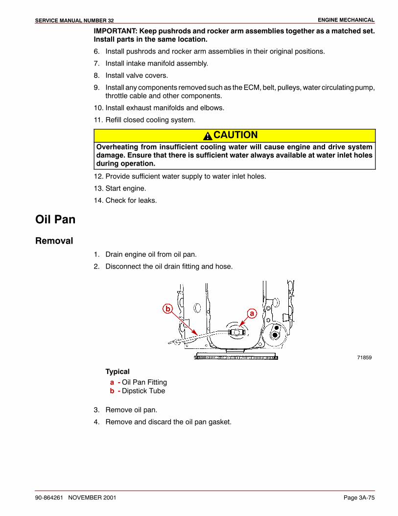
ENGINE MECHANICALSERVICE MANUAL NUMBER 32
90-864261 NOVEMBER 2001 Page 3A-75
IMPORTANT: Keep pushrods and rocker arm assemblies together as a matched set.Install parts in the same location.
6. Install pushrods and rocker arm assemblies in their original positions.
7. Install intake manifold assembly.
8. Install valve covers.
9. Install any components removedsuchas theECM,belt, pulleys,water circulatingpump,throttle cable and other components.
10. Install exhaust manifolds and elbows.
11. Refill closed cooling system.
CAUTIONOverheating from insufficient cooling water will cause engine and drive systemdamage. Ensure that there is sufficient water always available at water inlet holesduring operation.
12. Provide sufficient water supply to water inlet holes.
13. Start engine.
14. Check for leaks.
Oil Pan
Removal1. Drain engine oil from oil pan.
2. Disconnect the oil drain fitting and hose.
71859
ab
Typicala -Oil Pan Fittingb - Dipstick Tube
3. Remove oil pan.
4. Remove and discard the oil pan gasket.
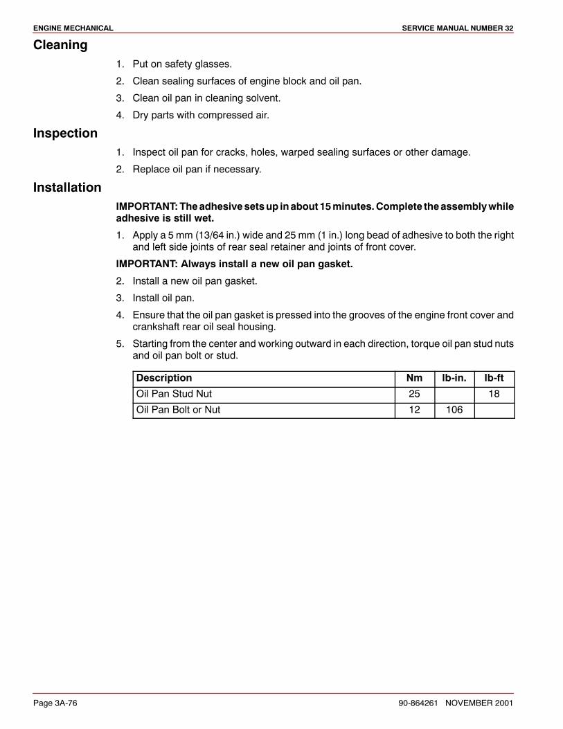
ENGINE MECHANICAL SERVICE MANUAL NUMBER 32
Page 3A-76 90-864261 NOVEMBER 2001
Cleaning1. Put on safety glasses.
2. Clean sealing surfaces of engine block and oil pan.
3. Clean oil pan in cleaning solvent.
4. Dry parts with compressed air.
Inspection1. Inspect oil pan for cracks, holes, warped sealing surfaces or other damage.
2. Replace oil pan if necessary.
InstallationIMPORTANT:Theadhesivesetsup inabout 15minutes.Complete theassemblywhileadhesive is still wet.
1. Apply a 5 mm (13/64 in.) wide and 25 mm (1 in.) long bead of adhesive to both the rightand left side joints of rear seal retainer and joints of front cover.
IMPORTANT: Always install a new oil pan gasket.
2. Install a new oil pan gasket.
3. Install oil pan.
4. Ensure that the oil pan gasket is pressed into the grooves of the engine front cover andcrankshaft rear oil seal housing.
5. Starting from the center and working outward in each direction, torque oil pan stud nutsand oil pan bolt or stud.
Description Nm lb-in. lb-ft
Oil Pan Stud Nut 25 18
Oil Pan Bolt or Nut 12 106
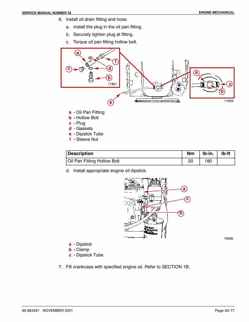
ENGINE MECHANICALSERVICE MANUAL NUMBER 32
90-864261 NOVEMBER 2001 Page 3A-77
6. Install oil drain fitting and hose.
a. Install the plug in the oil pan fitting.
b. Securely tighten plug at fitting.
c. Torque oil pan fitting hollow bolt.
71859
71861
e
a
cb
c d
b
f
a
a -Oil Pan Fittingb - Hollow Boltc - Plugd -Gasketse - Dipstick Tubef - Sleeve Nut
Description Nm lb-in. lb-ft
Oil Pan Fitting Hollow Bolt 20 180
d. Install appropriate engine oil dipstick.
76386
a
c
b
a - Dipstickb - Clampc - Dipstick Tube
7. Fill crankcase with specified engine oil. Refer to SECTION 1B.
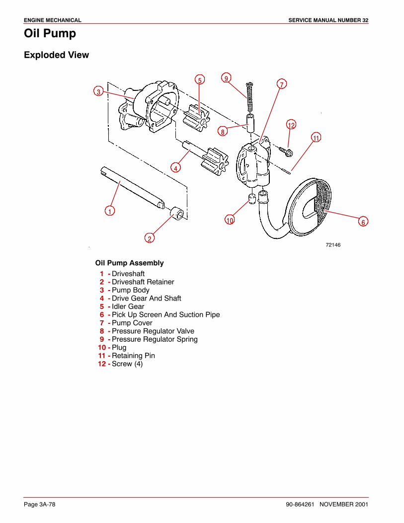
ENGINE MECHANICAL SERVICE MANUAL NUMBER 32
Page 3A-78 90-864261 NOVEMBER 2001
Oil Pump
Exploded View
72146
610
11
12
75 9
8
4
3
1
2
Oil Pump Assembly1 -Driveshaft2 -Driveshaft Retainer3 -Pump Body4 -Drive Gear And Shaft5 - Idler Gear6 -Pick Up Screen And Suction Pipe7 -Pump Cover8 -Pressure Regulator Valve9 -Pressure Regulator Spring10 -Plug11 -Retaining Pin12 -Screw (4)
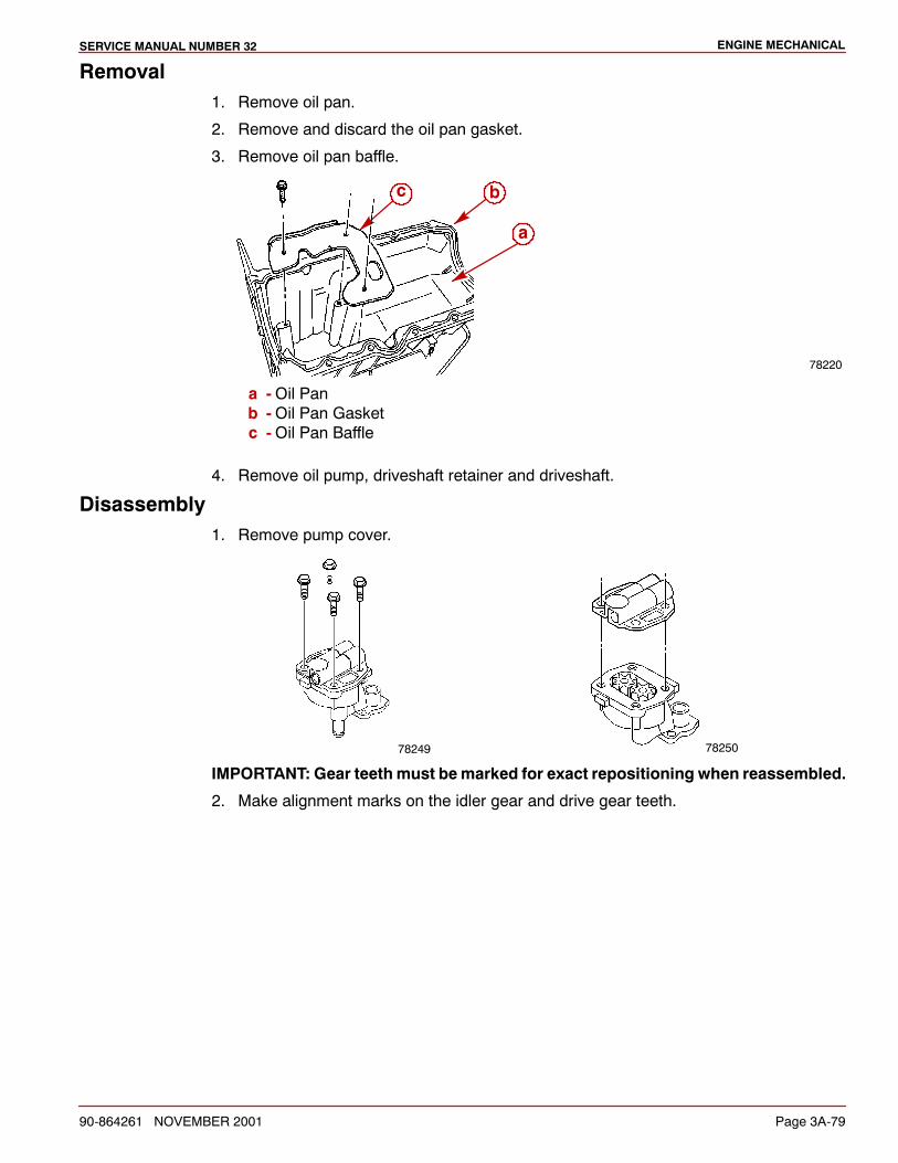
ENGINE MECHANICALSERVICE MANUAL NUMBER 32
90-864261 NOVEMBER 2001 Page 3A-79
Removal1. Remove oil pan.
2. Remove and discard the oil pan gasket.
3. Remove oil pan baffle.
78220
bc
a
a -Oil Panb -Oil Pan Gasketc -Oil Pan Baffle
4. Remove oil pump, driveshaft retainer and driveshaft.
Disassembly1. Remove pump cover.
78249 78250
IMPORTANT: Gear teethmust bemarked for exact repositioning when reassembled.
2. Make alignment marks on the idler gear and drive gear teeth.
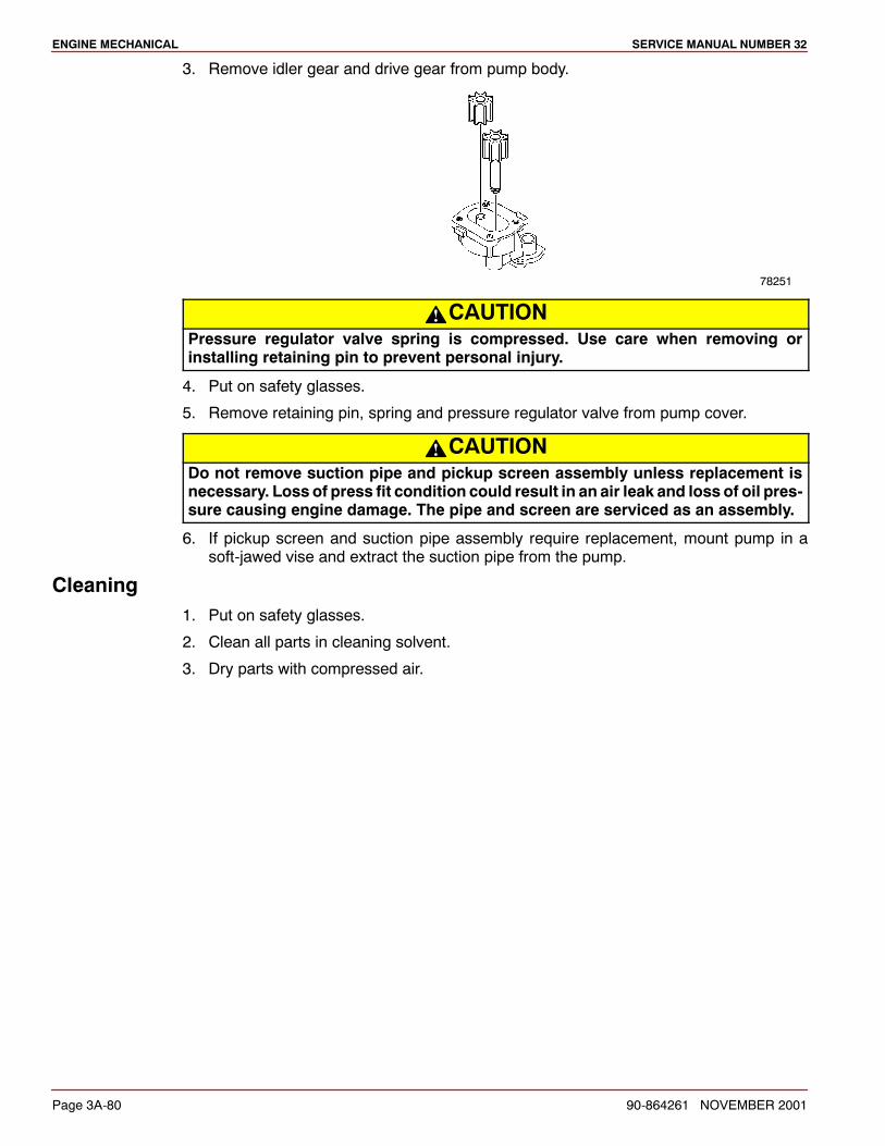
ENGINE MECHANICAL SERVICE MANUAL NUMBER 32
Page 3A-80 90-864261 NOVEMBER 2001
3. Remove idler gear and drive gear from pump body.
78251
CAUTIONPressure regulator valve spring is compressed. Use care when removing orinstalling retaining pin to prevent personal injury.
4. Put on safety glasses.
5. Remove retaining pin, spring and pressure regulator valve from pump cover.
CAUTIONDo not remove suction pipe and pickup screen assembly unless replacement isnecessary. Loss of press fit condition could result in an air leak and loss of oil pres-sure causing engine damage. The pipe and screen are serviced as an assembly.
6. If pickup screen and suction pipe assembly require replacement, mount pump in asoft-jawed vise and extract the suction pipe from the pump.
Cleaning1. Put on safety glasses.
2. Clean all parts in cleaning solvent.
3. Dry parts with compressed air.
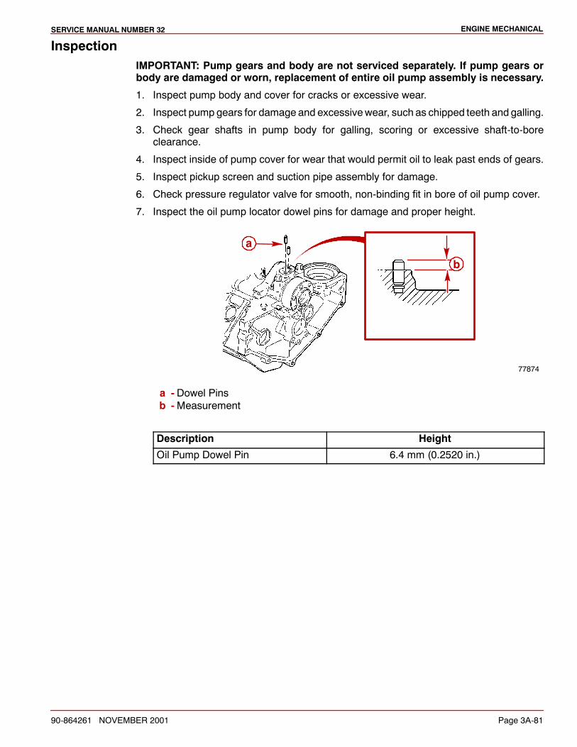
ENGINE MECHANICALSERVICE MANUAL NUMBER 32
90-864261 NOVEMBER 2001 Page 3A-81
InspectionIMPORTANT: Pump gears and body are not serviced separately. If pump gears orbody are damaged or worn, replacement of entire oil pump assembly is necessary.
1. Inspect pump body and cover for cracks or excessive wear.
2. Inspect pump gears for damage and excessivewear, such as chipped teeth and galling.
3. Check gear shafts in pump body for galling, scoring or excessive shaft-to-boreclearance.
4. Inspect inside of pump cover for wear that would permit oil to leak past ends of gears.
5. Inspect pickup screen and suction pipe assembly for damage.
6. Check pressure regulator valve for smooth, non-binding fit in bore of oil pump cover.
7. Inspect the oil pump locator dowel pins for damage and proper height.
77874
a
b
a - Dowel Pinsb -Measurement
Description Height
Oil Pump Dowel Pin 6.4 mm (0.2520 in.)
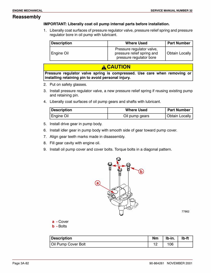
ENGINE MECHANICAL SERVICE MANUAL NUMBER 32
Page 3A-82 90-864261 NOVEMBER 2001
ReassemblyIMPORTANT: Liberally coat oil pump internal parts before installation.
1. Liberally coat surfaces of pressure regulator valve, pressure relief spring and pressureregulator bore in oil pump with lubricant.
Description Where Used Part Number
Engine OilPressure regulator valve,pressure relief spring andpressure regulator bore
Obtain Locally
CAUTIONPressure regulator valve spring is compressed. Use care when removing orinstalling retaining pin to avoid personal injury.
2. Put on safety glasses.
3. Install pressure regulator valve, a new pressure relief spring if reusing existing pumpand retaining pin.
4. Liberally coat surfaces of oil pump gears and shafts with lubricant.
Description Where Used Part Number
Engine Oil Oil pump gears Obtain Locally
5. Install drive gear in pump body.
6. Install idler gear in pump body with smooth side of gear toward pump cover.
7. Align gear teeth marks made in disassembly.
8. Fill gear cavity with engine oil.
9. Install oil pump cover and cover bolts. Torque bolts in a diagonal pattern.
77862
a
b
a - Coverb - Bolts
Description Nm lb-in. lb-ft
Oil Pump Cover Bolt 12 106
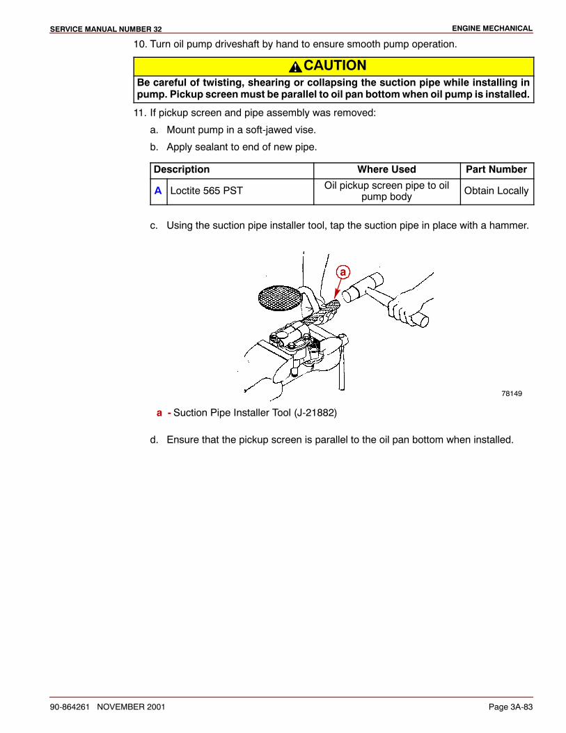
ENGINE MECHANICALSERVICE MANUAL NUMBER 32
90-864261 NOVEMBER 2001 Page 3A-83
10. Turn oil pump driveshaft by hand to ensure smooth pump operation.
CAUTIONBe careful of twisting, shearing or collapsing the suction pipe while installing inpump. Pickup screenmust be parallel to oil pan bottomwhen oil pump is installed.
11. If pickup screen and pipe assembly was removed:
a. Mount pump in a soft-jawed vise.
b. Apply sealant to end of new pipe.
Description Where Used Part Number
A Loctite 565 PST Oil pickup screen pipe to oilpump body Obtain Locally
c. Using the suction pipe installer tool, tap the suction pipe in place with a hammer.
78149
a
a - Suction Pipe Installer Tool (J-21882)
d. Ensure that the pickup screen is parallel to the oil pan bottom when installed.
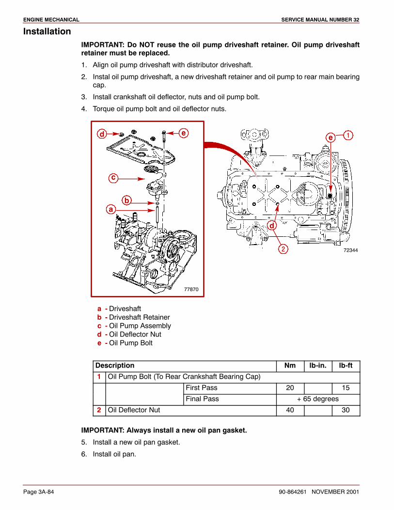
ENGINE MECHANICAL SERVICE MANUAL NUMBER 32
Page 3A-84 90-864261 NOVEMBER 2001
InstallationIMPORTANT: Do NOT reuse the oil pump driveshaft retainer. Oil pump driveshaftretainer must be replaced.
1. Align oil pump driveshaft with distributor driveshaft.
2. Instal oil pump driveshaft, a new driveshaft retainer and oil pump to rear main bearingcap.
3. Install crankshaft oil deflector, nuts and oil pump bolt.
4. Torque oil pump bolt and oil deflector nuts.
72344
1
77870
ab
c
d e e
d
2
a - Driveshaftb - Driveshaft Retainerc -Oil Pump Assemblyd -Oil Deflector Nute -Oil Pump Bolt
Description Nm lb-in. lb-ft
1 Oil Pump Bolt (To Rear Crankshaft Bearing Cap)
First Pass 20 15
Final Pass + 65 degrees
2 Oil Deflector Nut 40 30
IMPORTANT: Always install a new oil pan gasket.
5. Install a new oil pan gasket.
6. Install oil pan.
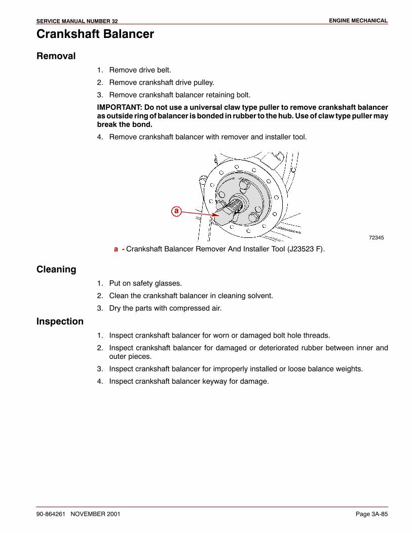
ENGINE MECHANICALSERVICE MANUAL NUMBER 32
90-864261 NOVEMBER 2001 Page 3A-85
Crankshaft Balancer
Removal1. Remove drive belt.
2. Remove crankshaft drive pulley.
3. Remove crankshaft balancer retaining bolt.
IMPORTANT: Do not use a universal claw type puller to remove crankshaft balancerasoutside ringof balancer isbonded in rubber to thehub.Useof claw typepullermaybreak the bond.
4. Remove crankshaft balancer with remover and installer tool.
72345
a
a - Crankshaft Balancer Remover And Installer Tool (J23523 F).
Cleaning1. Put on safety glasses.
2. Clean the crankshaft balancer in cleaning solvent.
3. Dry the parts with compressed air.
Inspection1. Inspect crankshaft balancer for worn or damaged bolt hole threads.
2. Inspect crankshaft balancer for damaged or deteriorated rubber between inner andouter pieces.
3. Inspect crankshaft balancer for improperly installed or loose balance weights.
4. Inspect crankshaft balancer keyway for damage.

ENGINE MECHANICAL SERVICE MANUAL NUMBER 32
Page 3A-86 90-864261 NOVEMBER 2001
InstallationIMPORTANT: The inertia weight section of the crankshaft balancer is bonded to thehub with a rubber type material. The installation procedure (with proper tool) mustbe followed or movement of the inertia weight on the hub will destroy the tuning ofthe crankshaft balancer.
1. Coat seal surface of crankshaft balancer with engine oil.
Description Where Used Part Number
Engine Oil Crankshaft Balancer SealSurface Obtain Locally
2. Replace crankshaft key if it is damaged.
3. To prevent oil leaks, apply sealant to crankshaft balancer keyway.
Description Where Used Part Number
Ultra-Black Loctite 5900 Crankshaft Balancer Keyway 92-809826
4. Align the keyway of the crankshaft balancer with the crankshaft balancer woodruff key.
5. Use theBalancer Remover and Installer Tool J23523-F to press the crankshaft balanceronto the crankshaft.
a. Install the plate and bolts onto the front of the crankshaft balancer and torque thebolts.
Description Nm lb-in. lb-ft
J23523-F Plate Bolts 25 18
b. Install the screw into the end of the crankshaft.
c. Install the bearing, the washer and the nut onto the screw.
d. Rotate the nut clockwise until the crankshaft balancer hub is completely seatedagainst the crankshaft position sensor reluctor ring.
6. Remove the Balancer Remover and Installer Tool.
72346a
a - Crankshaft Balancer Remover And Installer Tool (J23523-F)
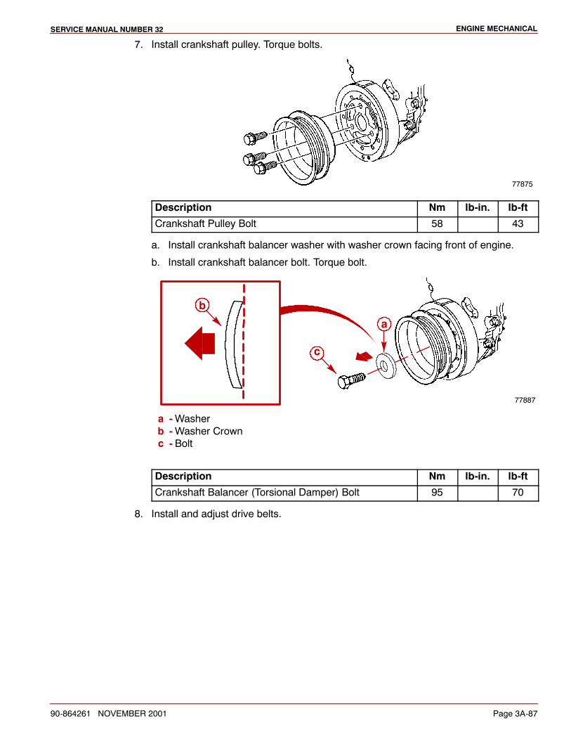
ENGINE MECHANICALSERVICE MANUAL NUMBER 32
90-864261 NOVEMBER 2001 Page 3A-87
7. Install crankshaft pulley. Torque bolts.
77875
Description Nm lb-in. lb-ft
Crankshaft Pulley Bolt 58 43
a. Install crankshaft balancer washer with washer crown facing front of engine.
b. Install crankshaft balancer bolt. Torque bolt.
77887
a
b
c
a -Washerb -Washer Crownc - Bolt
Description Nm lb-in. lb-ft
Crankshaft Balancer (Torsional Damper) Bolt 95 70
8. Install and adjust drive belts.
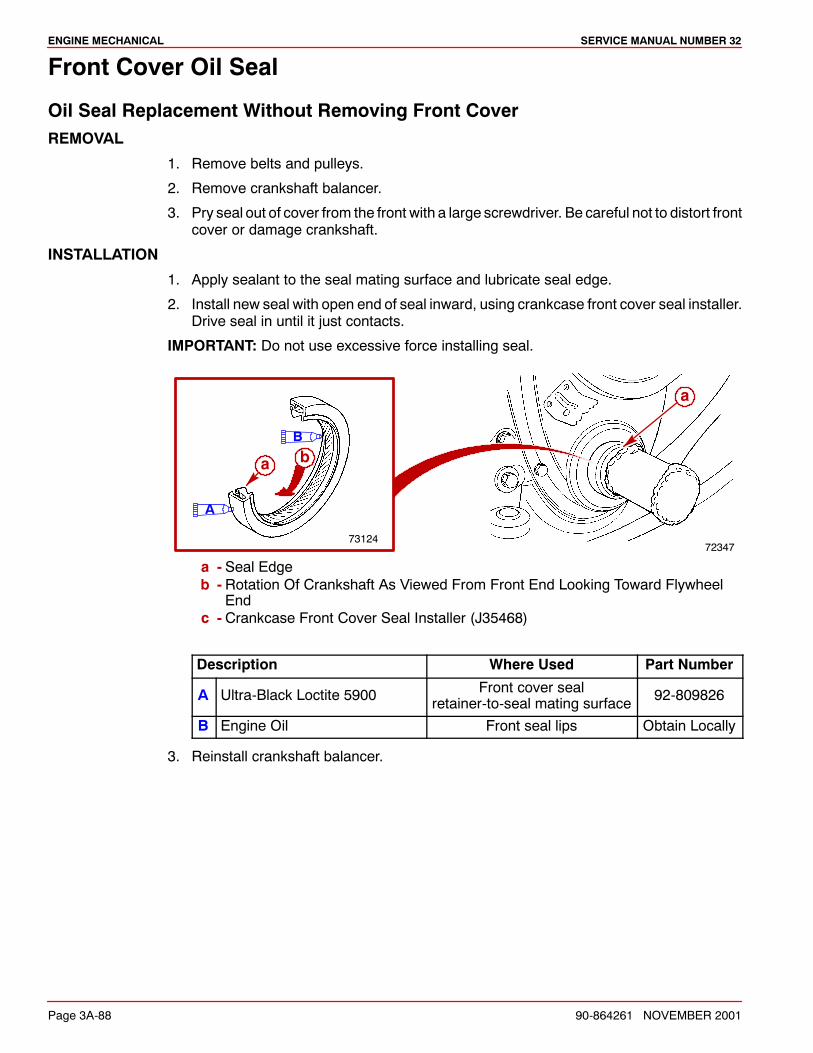
ENGINE MECHANICAL SERVICE MANUAL NUMBER 32
Page 3A-88 90-864261 NOVEMBER 2001
Front Cover Oil Seal
Oil Seal Replacement Without Removing Front CoverREMOVAL
1. Remove belts and pulleys.
2. Remove crankshaft balancer.
3. Pry seal out of cover from the front with a large screwdriver. Be careful not to distort frontcover or damage crankshaft.
INSTALLATION
1. Apply sealant to the seal mating surface and lubricate seal edge.
2. Install new seal with open end of seal inward, using crankcase front cover seal installer.Drive seal in until it just contacts.
IMPORTANT: Do not use excessive force installing seal.
72347
a
73124
ba
B
A
a - Seal Edgeb - Rotation Of Crankshaft As Viewed From Front End Looking Toward Flywheel
Endc - Crankcase Front Cover Seal Installer (J35468)
Description Where Used Part Number
A Ultra-Black Loctite 5900 Front cover sealretainer-to-seal mating surface 92-809826
B Engine Oil Front seal lips Obtain Locally
3. Reinstall crankshaft balancer.
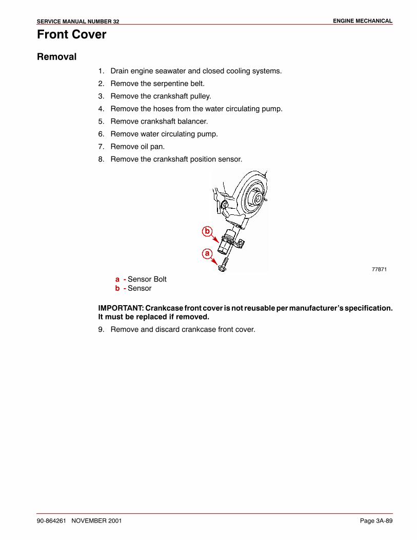
ENGINE MECHANICALSERVICE MANUAL NUMBER 32
90-864261 NOVEMBER 2001 Page 3A-89
Front Cover
Removal1. Drain engine seawater and closed cooling systems.
2. Remove the serpentine belt.
3. Remove the crankshaft pulley.
4. Remove the hoses from the water circulating pump.
5. Remove crankshaft balancer.
6. Remove water circulating pump.
7. Remove oil pan.
8. Remove the crankshaft position sensor.
77871
a
b
a - Sensor Boltb - Sensor
IMPORTANT:Crankcase front cover isnot reusablepermanufacturer’sspecification.It must be replaced if removed.
9. Remove and discard crankcase front cover.
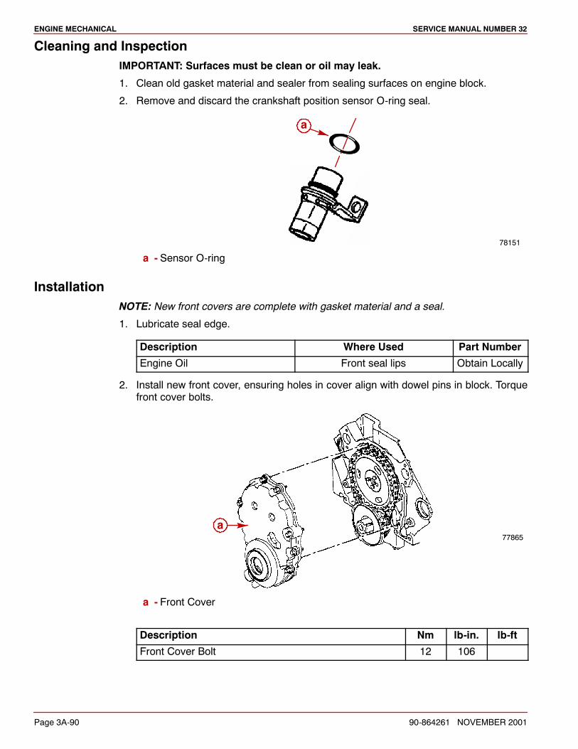
ENGINE MECHANICAL SERVICE MANUAL NUMBER 32
Page 3A-90 90-864261 NOVEMBER 2001
Cleaning and InspectionIMPORTANT: Surfaces must be clean or oil may leak.
1. Clean old gasket material and sealer from sealing surfaces on engine block.
2. Remove and discard the crankshaft position sensor O-ring seal.
78151
a
a - Sensor O-ring
InstallationNOTE: New front covers are complete with gasket material and a seal.
1. Lubricate seal edge.
Description Where Used Part Number
Engine Oil Front seal lips Obtain Locally
2. Install new front cover, ensuring holes in cover align with dowel pins in block. Torquefront cover bolts.
77865a
a - Front Cover
Description Nm lb-in. lb-ft
Front Cover Bolt 12 106
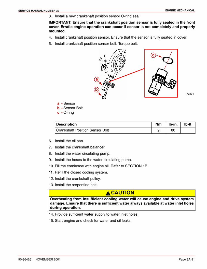
ENGINE MECHANICALSERVICE MANUAL NUMBER 32
90-864261 NOVEMBER 2001 Page 3A-91
3. Install a new crankshaft position sensor O-ring seal.
IMPORTANT: Ensure that the crankshaft position sensor is fully seated in the frontcover. Erratic engine operation can occur if sensor is not completely and properlymounted.
4. Install crankshaft position sensor. Ensure that the sensor is fully seated in cover.
5. Install crankshaft position sensor bolt. Torque bolt.
77871
a
b
c
a - Sensorb - Sensor Boltc -O-ring
Description Nm lb-in. lb-ft
Crankshaft Position Sensor Bolt 9 80
6. Install the oil pan.
7. Install the crankshaft balancer.
8. Install the water circulating pump.
9. Install the hoses to the water circulating pump.
10. Fill the crankcase with engine oil. Refer to SECTION 1B.
11. Refill the closed cooling system.
12. Install the crankshaft pulley.
13. Install the serpentine belt.
CAUTIONOverheating from insufficient cooling water will cause engine and drive systemdamage. Ensure that there is sufficient water always available at water inlet holesduring operation.
14. Provide sufficient water supply to water inlet holes.
15. Start engine and check for water and oil leaks.
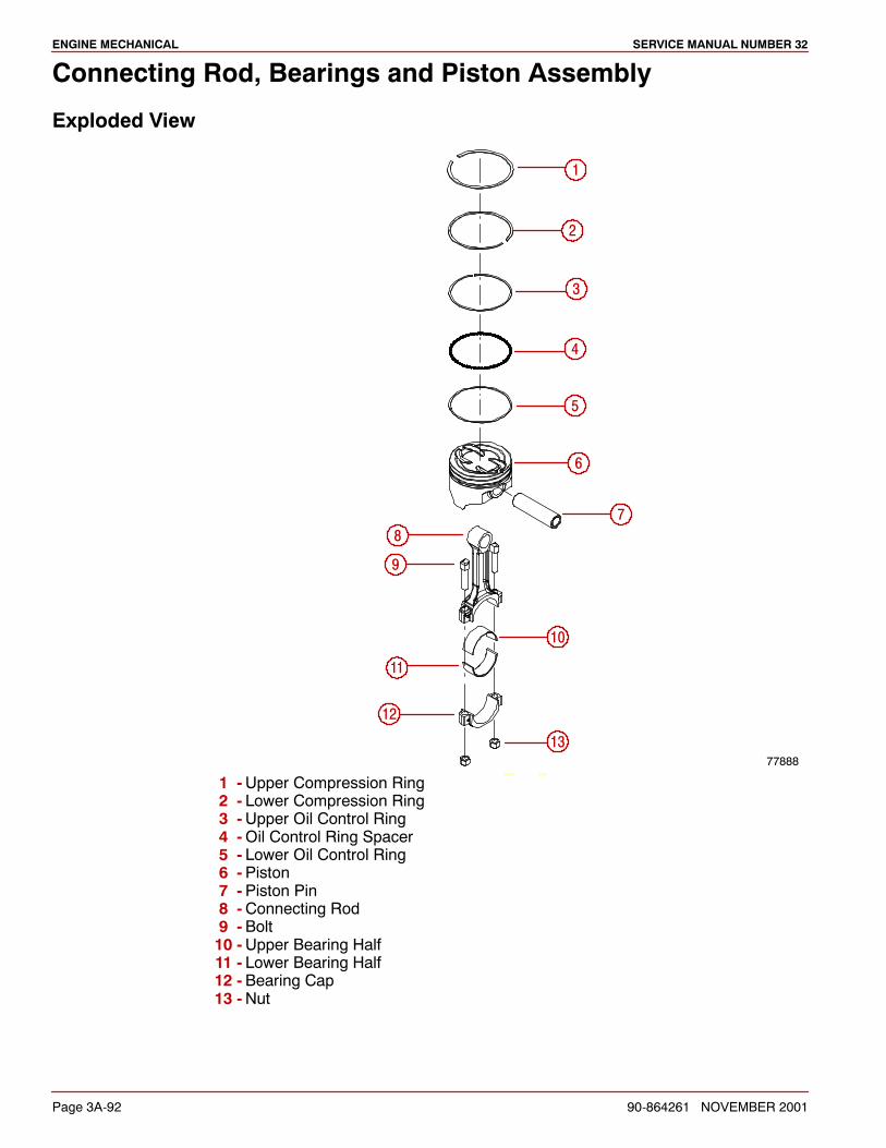
ENGINE MECHANICAL SERVICE MANUAL NUMBER 32
Page 3A-92 90-864261 NOVEMBER 2001
Connecting Rod, Bearings and Piston Assembly
Exploded View
77888SCALE 0.400
1
2
3
4
5
6
7
10
11
12
13
8
9
1 -Upper Compression Ring2 - Lower Compression Ring3 -Upper Oil Control Ring4 -Oil Control Ring Spacer5 - Lower Oil Control Ring6 -Piston7 -Piston Pin8 -Connecting Rod9 -Bolt10 -Upper Bearing Half11 - Lower Bearing Half12 -Bearing Cap13 -Nut
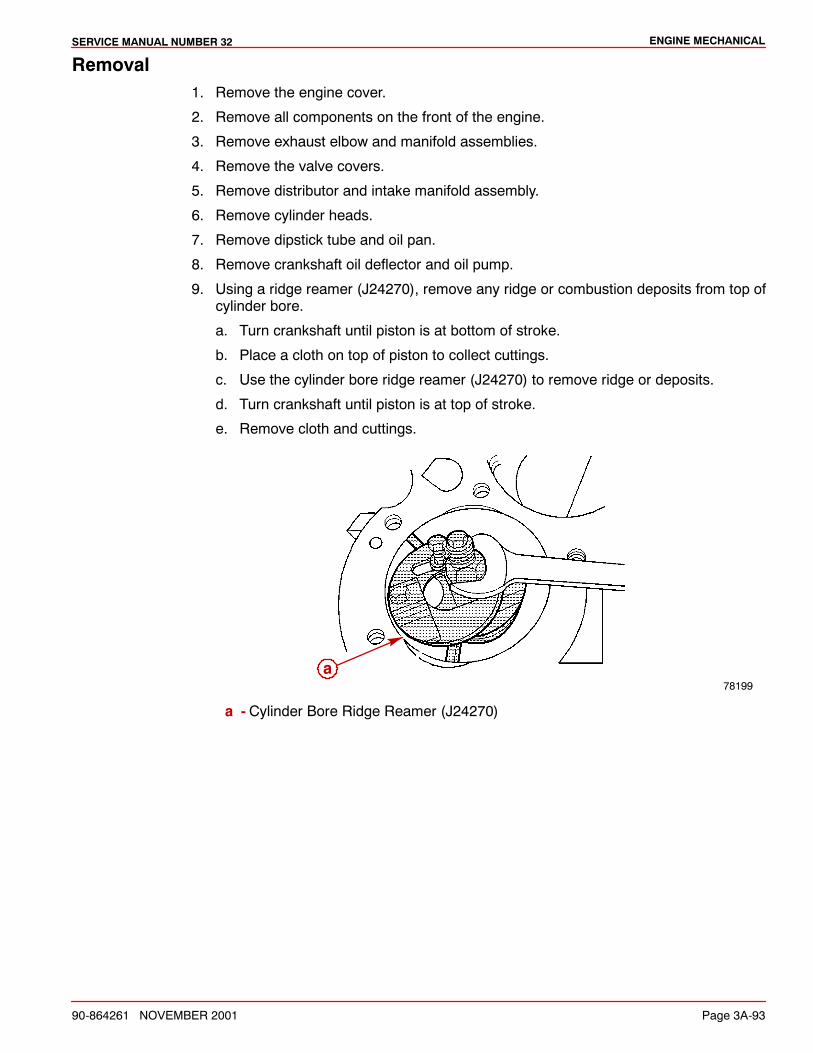
ENGINE MECHANICALSERVICE MANUAL NUMBER 32
90-864261 NOVEMBER 2001 Page 3A-93
Removal1. Remove the engine cover.
2. Remove all components on the front of the engine.
3. Remove exhaust elbow and manifold assemblies.
4. Remove the valve covers.
5. Remove distributor and intake manifold assembly.
6. Remove cylinder heads.
7. Remove dipstick tube and oil pan.
8. Remove crankshaft oil deflector and oil pump.
9. Using a ridge reamer (J24270), remove any ridge or combustion deposits from top ofcylinder bore.
a. Turn crankshaft until piston is at bottom of stroke.
b. Place a cloth on top of piston to collect cuttings.
c. Use the cylinder bore ridge reamer (J24270) to remove ridge or deposits.
d. Turn crankshaft until piston is at top of stroke.
e. Remove cloth and cuttings.
78199a
a - Cylinder Bore Ridge Reamer (J24270)
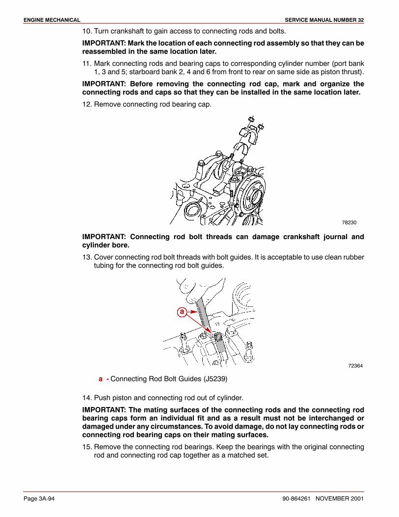
ENGINE MECHANICAL SERVICE MANUAL NUMBER 32
Page 3A-94 90-864261 NOVEMBER 2001
10. Turn crankshaft to gain access to connecting rods and bolts.
IMPORTANT: Mark the location of each connecting rod assembly so that they can bereassembled in the same location later.
11. Mark connecting rods and bearing caps to corresponding cylinder number (port bank1, 3 and 5; starboard bank 2, 4 and 6 from front to rear on same side as piston thrust).
IMPORTANT: Before removing the connecting rod cap, mark and organize theconnecting rods and caps so that they can be installed in the same location later.
12. Remove connecting rod bearing cap.
78230
IMPORTANT: Connecting rod bolt threads can damage crankshaft journal andcylinder bore.
13. Cover connecting rod bolt threads with bolt guides. It is acceptable to use clean rubbertubing for the connecting rod bolt guides.
72364
a
a - Connecting Rod Bolt Guides (J5239)
14. Push piston and connecting rod out of cylinder.
IMPORTANT: The mating surfaces of the connecting rods and the connecting rodbearing caps form an individual fit and as a result must not be interchanged ordamaged under any circumstances. To avoid damage, do not lay connecting rods orconnecting rod bearing caps on their mating surfaces.
15. Remove the connecting rod bearings. Keep the bearings with the original connectingrod and connecting rod cap together as a matched set.
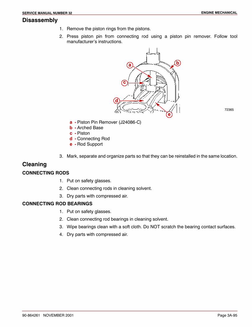
ENGINE MECHANICALSERVICE MANUAL NUMBER 32
90-864261 NOVEMBER 2001 Page 3A-95
Disassembly1. Remove the piston rings from the pistons.
2. Press piston pin from connecting rod using a piston pin remover. Follow toolmanufacturer’s instructions.
72365
b
e
c
d
a
a - Piston Pin Remover (J24086-C)b - Arched Basec - Pistond - Connecting Rode - Rod Support
3. Mark, separate and organize parts so that they can be reinstalled in the same location.
CleaningCONNECTING RODS
1. Put on safety glasses.
2. Clean connecting rods in cleaning solvent.
3. Dry parts with compressed air.
CONNECTING ROD BEARINGS
1. Put on safety glasses.
2. Clean connecting rod bearings in cleaning solvent.
3. Wipe bearings clean with a soft cloth. Do NOT scratch the bearing contact surfaces.
4. Dry parts with compressed air.
ENGINE MECHANICAL SERVICE MANUAL NUMBER 32
Page 3A-96 90-864261 NOVEMBER 2001
PISTONS
IMPORTANT: Do not wire brush any part of a piston.
1. Put on safety glasses.
2. Clean pistons in cleaning solvent.
3. Clean varnish from piston skirts and pins with a suitable cleaning solvent.
4. Clean piston ring grooves.
5. Clean piston oil lubrication holes and slots.
6. Dry parts with compressed air.
PISTON PIN
1. Put on safety glasses.
2. Clean parts in cleaning solvent and dry with compressed air.
3. Dry parts with compressed air.
InspectionIMPORTANT: Measurements should be taken when components are at roomtemperature.
CONNECTING ROD
1. Check for twisted and bent connecting rods.
2. Inspect for nicks and cracks.
3. Inspect for damage to the bearing cap and bolt threads.
CONNECTING ROD BEARINGS
NOTE:Refer toCrankshaft,MainBearings andEngineBlock -MainBearings, for examplesof bearing failures similar to the following.
1. Inspect the connecting rod bearings for craters, pockets or flattened sections.
2. Inspect the connecting rod bearings for excessive scoring, discoloration or damage.
3. Inspect the connecting rod bearings for dirt or debris imbedded in the bearing material.
4. Replace damaged or faulty bearings.
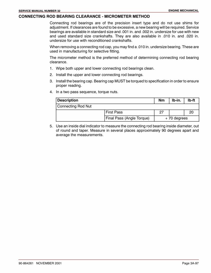
ENGINE MECHANICALSERVICE MANUAL NUMBER 32
90-864261 NOVEMBER 2001 Page 3A-97
CONNECTING ROD BEARING CLEARANCE - MICROMETER METHOD
Connecting rod bearings are of the precision insert type and do not use shims foradjustment. If clearances are found to be excessive, a newbearingwill be required. Servicebearings are available in standard size and .001 in. and .002 in. undersize for use with newand used standard size crankshafts. They are also available in .010 in. and .020 in.undersize for use with reconditioned crankshafts.
When removing a connecting rod cap, youmay find a .010 in. undersize bearing. These areused in manufacturing for selective fitting.
The micrometer method is the preferred method of determining connecting rod bearingclearance.
1. Wipe both upper and lower connecting rod bearings clean.
2. Install the upper and lower connecting rod bearings.
3. Install the bearing cap. Bearing capMUST be torqued to specification in order to ensureproper reading.
4. In a two pass sequence, torque nuts.
Description Nm lb-in. lb-ft
Connecting Rod Nut
First Pass 27 20
Final Pass (Angle Torque) + 70 degrees
5. Use an inside dial indicator to measure the connecting rod bearing inside diameter, outof round and taper. Measure in several places approximately 90 degrees apart andaverage the measurements.
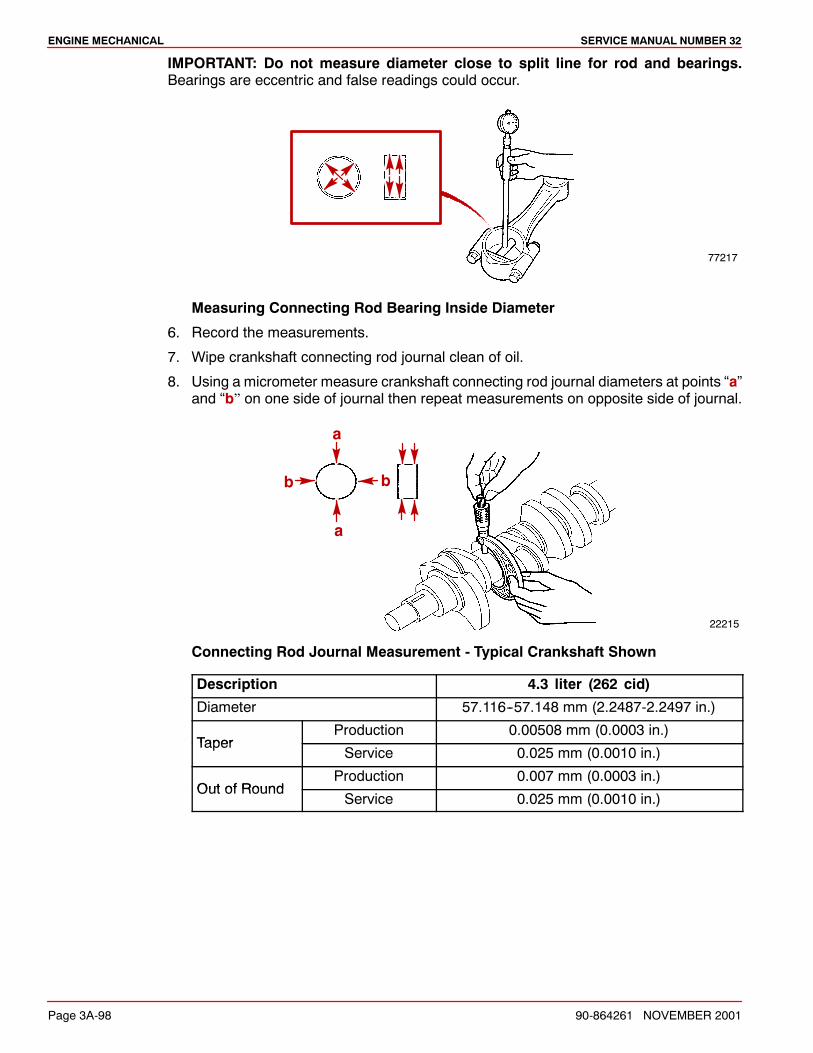
ENGINE MECHANICAL SERVICE MANUAL NUMBER 32
Page 3A-98 90-864261 NOVEMBER 2001
IMPORTANT: Do not measure diameter close to split line for rod and bearings.Bearings are eccentric and false readings could occur.
77217
Measuring Connecting Rod Bearing Inside Diameter
6. Record the measurements.
7. Wipe crankshaft connecting rod journal clean of oil.
8. Using a micrometer measure crankshaft connecting rod journal diameters at points “a”and “b” on one side of journal then repeat measurements on opposite side of journal.
22215
b
a
a
b
Connecting Rod Journal Measurement - Typical Crankshaft Shown
Description 4.3 liter (262 cid)
Diameter 57.116--57.148 mm (2.2487-2.2497 in.)
TaperProduction 0.00508 mm (0.0003 in.)
TaperService 0.025 mm (0.0010 in.)
Out of RoundProduction 0.007 mm (0.0003 in.)
Out of RoundService 0.025 mm (0.0010 in.)
ENGINE MECHANICALSERVICE MANUAL NUMBER 32
90-864261 NOVEMBER 2001 Page 3A-99
9. If journal diameters are not within specifications, replace or recondition the crankshaft.
CAUTIONAvoid bearing failure. If a bearing is being fitted to an out-of-round journal, be sureto fit bearing to the maximum diameter of the journal. If the bearing is fitted to theminimum diameter and the journal is out of round 0.0254 mm (0.001 in.),interference between the bearing and journal will result in rapid bearing failure.
10. If journal diameters are within specifications, determine bearing clearance bysubtracting thecrankshaft connecting rod journal outer diameter from the innerdiameterof the bearing.
Description 4.3 liter (262 cid)
ClearanceProduction 0.038-0.078 mm (0.0015-0.0031 in.)
ClearanceService Limit 0.025-0.063 mm (0.0010-0.0025 in.)
11. If the clearance exceeds specifications, select a new, correct size bearing anddetermine the clearance.
CONNECTING ROD BEARING CLEARANCE -- PLASTIC GAUGE METHOD
The plastic gauge method is an optional method of determining connecting rod bearingclearance. The preferred method use a micrometer.
1. Wipe both upper and lower bearings and crankshaft connecting rod journal clean of oil.
2. Install the bearings in the connecting rod and cap.
CAUTIONAvoid possible engine bearing failure. The connecting rod and upper bearingmustbeseatedagainst theconnecting rod journal before installing the lowerbearingandrodcap.Unreliablemeasurementmay result if the journal andupperbearingarenotfully seated.
3. Rotate the crankshaft or move the connecting rod until the upper bearing is fully seatedagainst the connecting rod journal being measured.
IMPORTANT: Position the gauging plastic on the crankshaft journal in an area thatwill be the middle of the bearing shell.
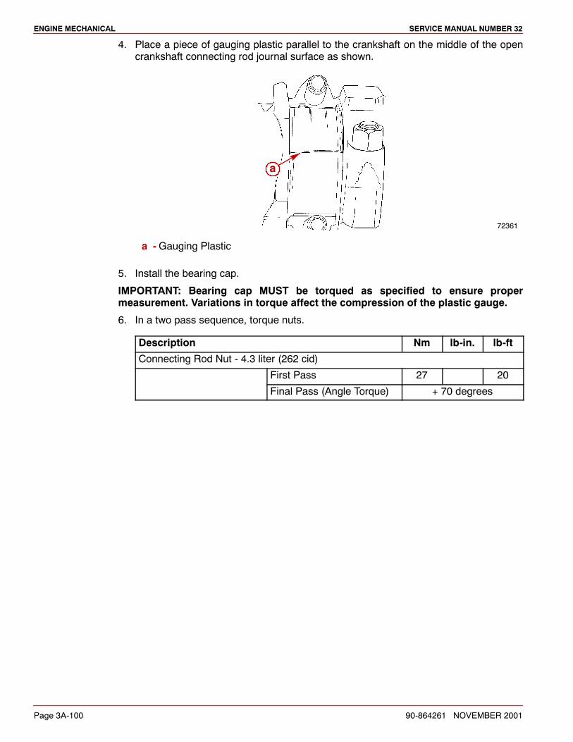
ENGINE MECHANICAL SERVICE MANUAL NUMBER 32
Page 3A-100 90-864261 NOVEMBER 2001
4. Place a piece of gauging plastic parallel to the crankshaft on the middle of the opencrankshaft connecting rod journal surface as shown.
72361
a
a -Gauging Plastic
5. Install the bearing cap.
IMPORTANT: Bearing cap MUST be torqued as specified to ensure propermeasurement. Variations in torque affect the compression of the plastic gauge.
6. In a two pass sequence, torque nuts.
Description Nm lb-in. lb-ft
Connecting Rod Nut - 4.3 liter (262 cid)
First Pass 27 20
Final Pass (Angle Torque) + 70 degrees

ENGINE MECHANICALSERVICE MANUAL NUMBER 32
90-864261 NOVEMBER 2001 Page 3A-101
IMPORTANT: Do not rotate the crankshaft while the gauging plastic is between thebearing and journal.
7. Without rotating crankshaft, remove the bearing cap and use the scale on the gaugingplastic envelope to measure the gauging plastic width at the widest point.
72362
Measuring Connecting Rod Bearing Clearance
Description 4.3 liter (262 cid )
ClearanceProduction 0.038-0.078 mm (0.0015-0.0031 in.)
ClearanceService Limit 0.025-0.063 mm (0.0010-0.0025 in.)
8. If the clearance exceeds specifications, select a new, correct size bearing andremeasure the clearance. A standard and undersized connecting rod bearingcombination may result in the proper clearance.
NOTE: If clearance cannot be brought to within specifications, the crankshaft connectingrod journal will have to be ground undersize. If the connecting rod journal is already atmaximum undersize, replace crankshaft.
9. Coat the selected bearing surface with oil.
10. Install the rod cap.
11. In a two pass sequence, torque nuts.
Description Nm lb-in. lb-ft
Connecting Rod Nut - 4.3 liter (262 cid)
First Pass 27 20
Final Pass (Angle Torque) + 70 degrees
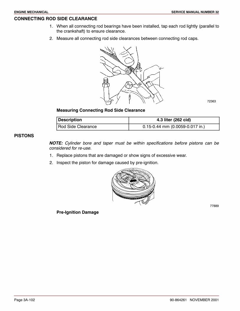
ENGINE MECHANICAL SERVICE MANUAL NUMBER 32
Page 3A-102 90-864261 NOVEMBER 2001
CONNECTING ROD SIDE CLEARANCE
1. When all connecting rod bearings have been installed, tap each rod lightly (parallel tothe crankshaft) to ensure clearance.
2. Measure all connecting rod side clearances between connecting rod caps.
72363
Measuring Connecting Rod Side Clearance
Description 4.3 liter (262 cid)
Rod Side Clearance 0.15-0.44 mm (0.0059-0.017 in.)
PISTONS
NOTE: Cylinder bore and taper must be within specifications before pistons can beconsidered for re-use.
1. Replace pistons that are damaged or show signs of excessive wear.
2. Inspect the piston for damage caused by pre-ignition.
77889
Pre-Ignition Damage
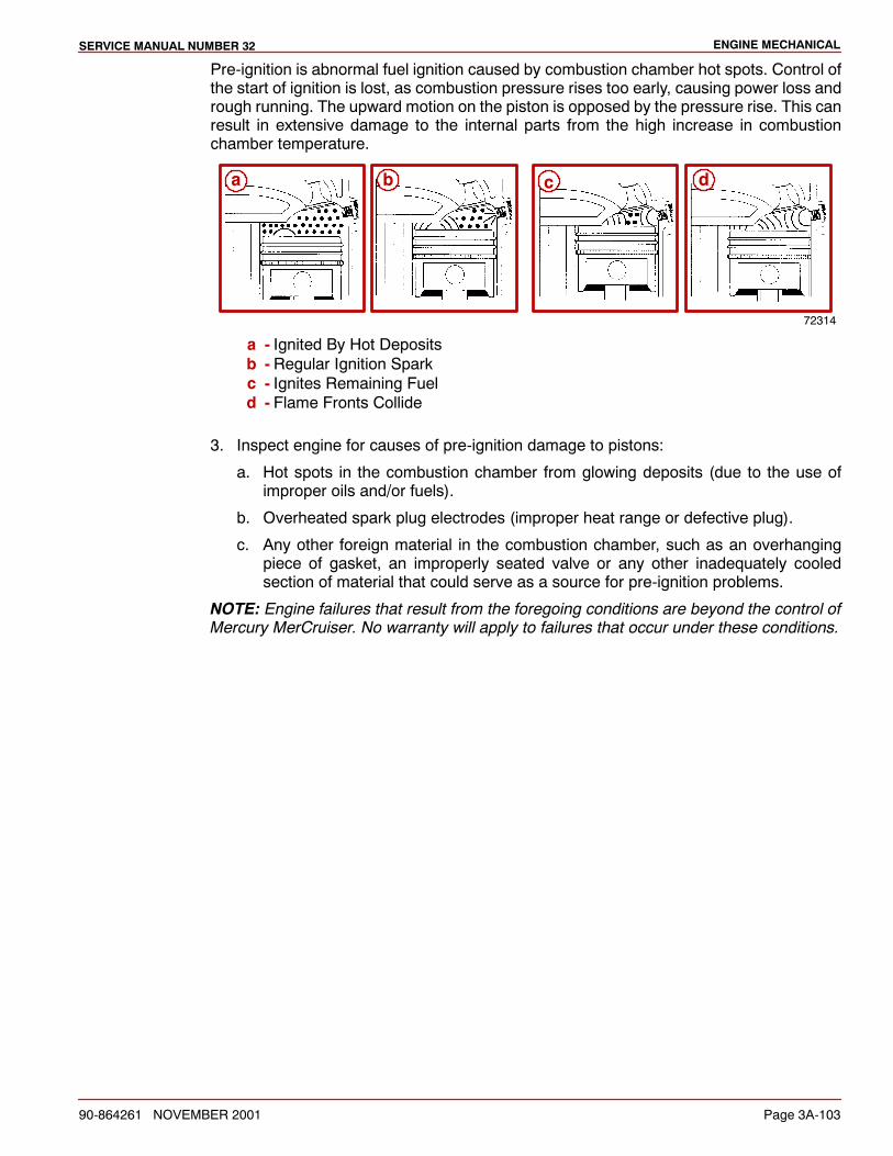
ENGINE MECHANICALSERVICE MANUAL NUMBER 32
90-864261 NOVEMBER 2001 Page 3A-103
Pre-ignition is abnormal fuel ignition caused by combustion chamber hot spots. Control ofthe start of ignition is lost, as combustion pressure rises too early, causing power loss andrough running. The upward motion on the piston is opposed by the pressure rise. This canresult in extensive damage to the internal parts from the high increase in combustionchamber temperature.
72314
a b c d
a - Ignited By Hot Depositsb - Regular Ignition Sparkc - Ignites Remaining Fueld - Flame Fronts Collide
3. Inspect engine for causes of pre-ignition damage to pistons:
a. Hot spots in the combustion chamber from glowing deposits (due to the use ofimproper oils and/or fuels).
b. Overheated spark plug electrodes (improper heat range or defective plug).
c. Any other foreign material in the combustion chamber, such as an overhangingpiece of gasket, an improperly seated valve or any other inadequately cooledsection of material that could serve as a source for pre-ignition problems.
NOTE: Engine failures that result from the foregoing conditions are beyond the control ofMercury MerCruiser. No warranty will apply to failures that occur under these conditions.

ENGINE MECHANICAL SERVICE MANUAL NUMBER 32
Page 3A-104 90-864261 NOVEMBER 2001
4. Inspect the piston for damage caused by detonation.
Detonation, commonly called fuel knock, spark knock or carbon knock, is abnormalcombustion of the fuel causing the fuel to explode violently. The explosion causesoverheating or damage to the spark plugs, pistons, valves and, in severe cases, results inpre-ignition.
77889
Detonation Damage
72315
a b c d
a - Spark Occursb - Combustion Beginsc - Combustion Continuesd - Detonation Occurs
5. Inspect engine for causes of detonation damage to pistons:
IMPORTANT:Useof improper fuelswill causeenginedamageandpoorperformance.
a. Use of low octane gasoline or neglecting engine maintenance.
b. Lean fuelmixture at or near full throttle (could be caused by leaking intakemanifold).
c. Cross-firing spark plugs.
d. Excess accumulation of deposits on piston and/or combustion chamber that resultin higher compression ratio.
e. Inadequate cooling of engine due to deterioration of cooling system.
NOTE: Engine failures that result from the foregoing conditions are beyond the control ofMercury MerCruiser. No warranty will apply to failures that occur under these conditions.
6. Inspect piston for cracked ring lands, skirts and pin bosses, wavy or worn ring lands,scuffed or damaged skirts and eroded areas at top of piston.
7. Inspect ring grooves for nicks and burrs that might cause rings to bind.

ENGINE MECHANICALSERVICE MANUAL NUMBER 32
90-864261 NOVEMBER 2001 Page 3A-105
8. Inspect piston wear by checking clearance as follows:
a. Measure piston diameter 11 mm (0.433 in.) from the bottom of the skirt at a rightangle to the piston pin bore as shown.
72624
Measuring Piston Diameter
b. Measure cylinder bore diameter with a telescope gauge 64 mm (2-1/2 in.) from topof cylinder bore at 90 degrees from crankshaft centerline as follows.
72386
Measuring Cylinder Bore
Description 4.3 liter (262 cid)
Diameter 101.618-101.643 mm(4.0007-4.0017 in.)
Out Of RoundProduction 0.0127 mm (0.0005
in.) MaximumOut Of Round
Service 0.05 mm (0.0020 in.)Maximum
Production -Thrust Side
0.012 mm (0.0005in.) Maximum
TaperProduction -Relief Side
0.025 mm (0.0010in.) Maximum
Service 0.025 mm (0.0010in.) Over Production
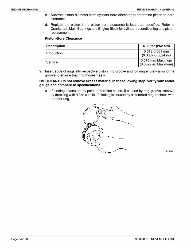
ENGINE MECHANICAL SERVICE MANUAL NUMBER 32
Page 3A-106 90-864261 NOVEMBER 2001
c. Subtract piston diameter from cylinder bore diameter to determine piston-to-boreclearance.
d. Replace the piston if the piston bore clearance is less than specified. Refer toCrankshaft, Main Bearings and Engine Block for cylinder reconditioning and pistonreplacement.
Piston-Bore Clearance
Description 4.3 liter (262 cid)
Production 0.018-0.061 mm(0.0007-0.0024 in.)
Service 0.075 mm Maximum(0.0029 in. Maximum)
9. Insert edge of rings into respective piston ring groove and roll ring entirely around thegroove to ensure that ring moves freely.
IMPORTANT: Do not remove excess material in the following step. Verify with feelergauge and compare to specifications.
a. If binding occurs at any point, determine cause. If caused by ring groove, removeby dressing with a fine cut file. If binding is caused by a distorted ring, recheck withanother ring.
72366
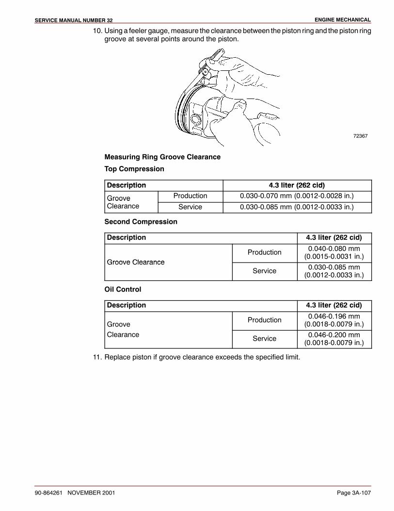
ENGINE MECHANICALSERVICE MANUAL NUMBER 32
90-864261 NOVEMBER 2001 Page 3A-107
10. Using a feeler gauge,measure the clearance between the piston ring and the piston ringgroove at several points around the piston.
72367
Measuring Ring Groove Clearance
Top Compression
Description 4 3 liter (262 cid)Description 4.3 liter (262 cid)
Groove Production 0.030-0.070 mm (0.0012-0.0028 in.)GrooveClearance Service 0.030-0.085 mm (0.0012-0.0033 in.)
Second Compression
Description 4.3 liter (262 cid)
Groove ClearanceProduction 0.040-0.080 mm
(0.0015-0.0031 in.)Groove Clearance
Service 0.030-0.085 mm(0.0012-0.0033 in.)
Oil Control
Description 4.3 liter (262 cid)
GrooveProduction 0.046-0.196 mm
(0.0018-0.0079 in.)Clearance Service 0.046-0.200 mm
(0.0018-0.0079 in.)
11. Replace piston if groove clearance exceeds the specified limit.
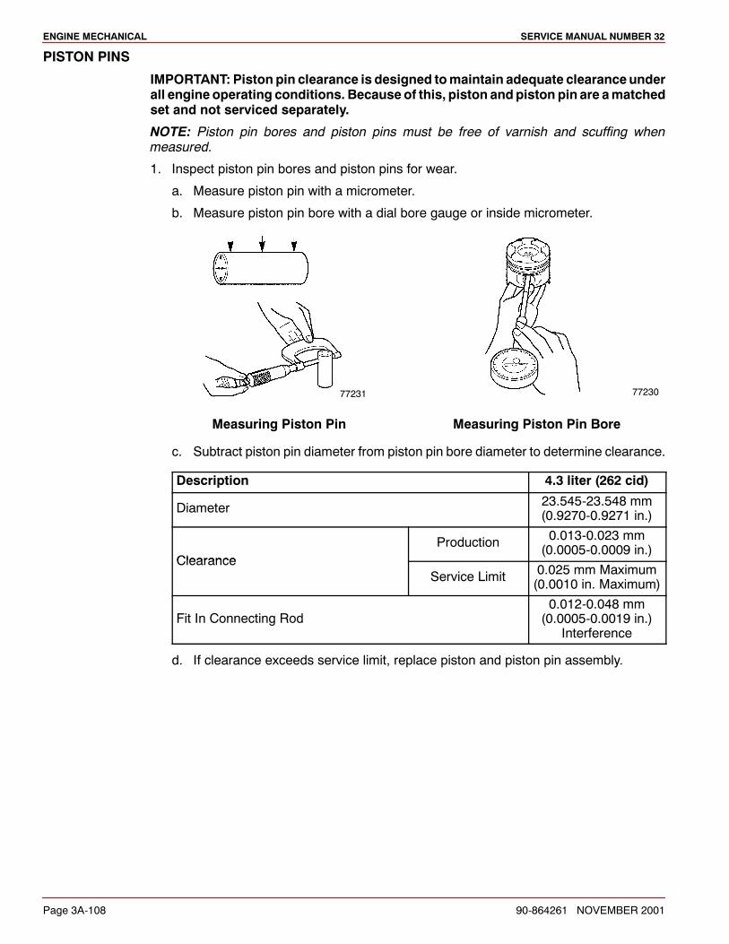
ENGINE MECHANICAL SERVICE MANUAL NUMBER 32
Page 3A-108 90-864261 NOVEMBER 2001
PISTON PINS
IMPORTANT: Piston pin clearance is designed tomaintain adequate clearanceunderall engine operating conditions. Because of this, piston andpiston pin are amatchedset and not serviced separately.
NOTE: Piston pin bores and piston pins must be free of varnish and scuffing whenmeasured.
1. Inspect piston pin bores and piston pins for wear.
a. Measure piston pin with a micrometer.
b. Measure piston pin bore with a dial bore gauge or inside micrometer.
77231 77230
Measuring Piston Pin Measuring Piston Pin Bore
c. Subtract piston pin diameter from piston pin bore diameter to determine clearance.
Description 4.3 liter (262 cid)
Diameter 23.545-23.548 mm(0.9270-0.9271 in.)
ClearanceProduction 0.013-0.023 mm
(0.0005-0.0009 in.)Clearance
Service Limit 0.025 mm Maximum(0.0010 in. Maximum)
Fit In Connecting Rod0.012-0.048 mm(0.0005-0.0019 in.)
Interference
d. If clearance exceeds service limit, replace piston and piston pin assembly.
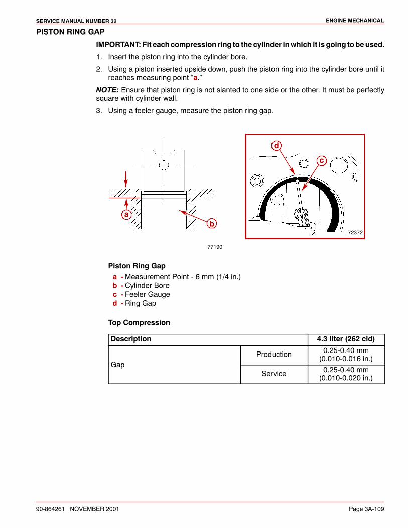
ENGINE MECHANICALSERVICE MANUAL NUMBER 32
90-864261 NOVEMBER 2001 Page 3A-109
PISTON RING GAP
IMPORTANT: Fit eachcompression ring to thecylinder inwhich it is going to beused.
1. Insert the piston ring into the cylinder bore.
2. Using a piston inserted upside down, push the piston ring into the cylinder bore until itreaches measuring point “a.”
NOTE: Ensure that piston ring is not slanted to one side or the other. It must be perfectlysquare with cylinder wall.
3. Using a feeler gauge, measure the piston ring gap.
77190
a
72372
d
c
b
Piston Ring Gapa -Measurement Point - 6 mm (1/4 in.)b - Cylinder Borec - Feeler Gauged - Ring Gap
Top Compression
Description 4.3 liter (262 cid)
GapProduction 0.25-0.40 mm
(0.010-0.016 in.)Gap
Service 0.25-0.40 mm(0.010-0.020 in.)
ENGINE MECHANICAL SERVICE MANUAL NUMBER 32
Page 3A-110 90-864261 NOVEMBER 2001
Second Compression
Description 4.3 liter (262 cid)
GapProduction 0.46-0.66 mm
(0.018-0.026 in.)Gap
Service 0.46-0.90 mm(0.018-0.035 in.)
Oil Control
Description 4.3 liter (262 cid)
GapProduction 0.25-0.76 mm
(0.0098-0.030 in.)Gap
Service 0.25-0.89 mm(0.0098-0.035 in.)
4. Replace ring if gap exceeds service limits. If gap between ends of ring is belowspecifications, remove ring and try another.

ENGINE MECHANICALSERVICE MANUAL NUMBER 32
90-864261 NOVEMBER 2001 Page 3A-111
ReassemblyIMPORTANT: When reassembling pistons and connecting rods, the following mustbe kept in mind.
Piston and pin are machine fitted to each other and must remain together as amatched set. Do not intermix pistons and pins.
If original pistons and/or connecting rods are being used, be sure to assemblepistons and connecting rods so they can be reinstalled in same cylinder fromwhich they were removed.
Connecting rod bearing tangs are always toward outside of engine block.
72368
a
a - Connecting Rod Bearing Tangs
Notch on the piston must be positioned toward the front of the engine (waterpump end).
72369
a
a - Notch
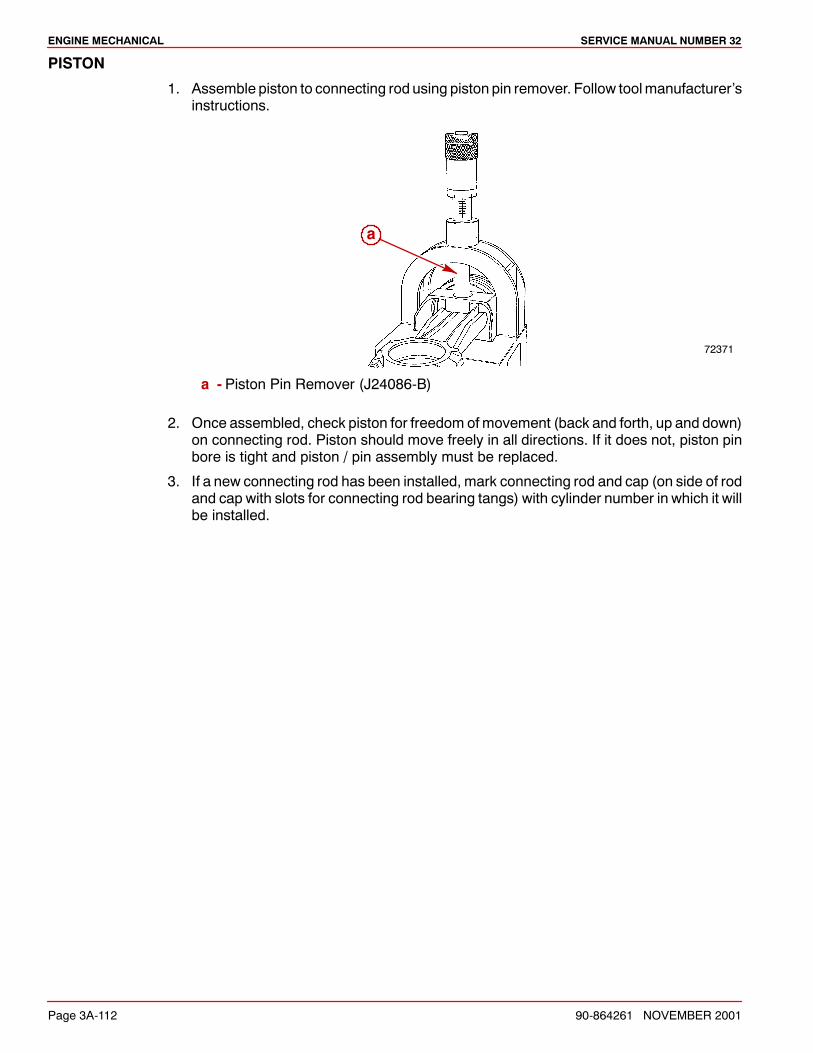
ENGINE MECHANICAL SERVICE MANUAL NUMBER 32
Page 3A-112 90-864261 NOVEMBER 2001
PISTON
1. Assemble piston to connecting rod using piston pin remover. Follow toolmanufacturer’sinstructions.
72371
a
a - Piston Pin Remover (J24086-B)
2. Once assembled, check piston for freedom ofmovement (back and forth, up and down)on connecting rod. Piston should move freely in all directions. If it does not, piston pinbore is tight and piston / pin assembly must be replaced.
3. If a new connecting rod has been installed, mark connecting rod and cap (on side of rodand cap with slots for connecting rod bearing tangs) with cylinder number in which it willbe installed.
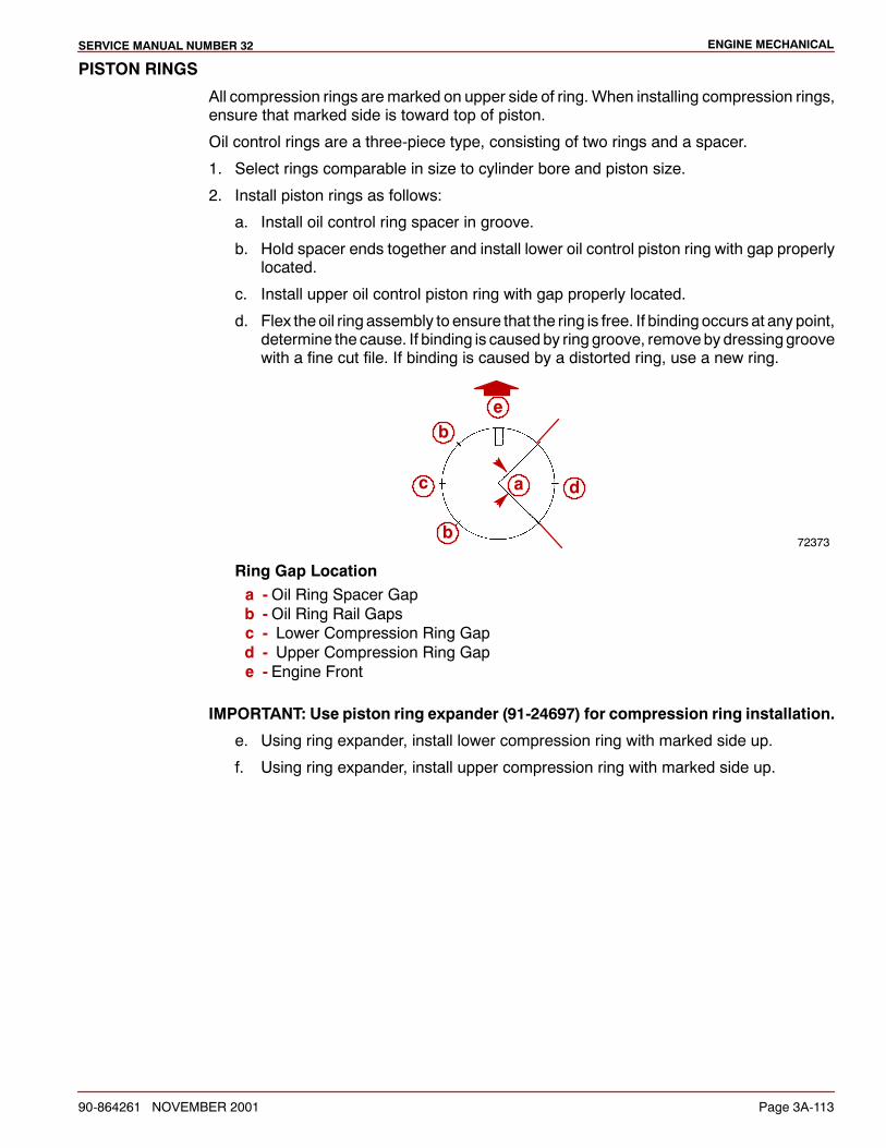
ENGINE MECHANICALSERVICE MANUAL NUMBER 32
90-864261 NOVEMBER 2001 Page 3A-113
PISTON RINGS
All compression rings aremarked on upper side of ring. When installing compression rings,ensure that marked side is toward top of piston.
Oil control rings are a three-piece type, consisting of two rings and a spacer.
1. Select rings comparable in size to cylinder bore and piston size.
2. Install piston rings as follows:
a. Install oil control ring spacer in groove.
b. Hold spacer ends together and install lower oil control piston ring with gap properlylocated.
c. Install upper oil control piston ring with gap properly located.
d. Flex the oil ring assembly to ensure that the ring is free. If binding occurs at any point,determine the cause. If binding is causedby ring groove, removeby dressinggroovewith a fine cut file. If binding is caused by a distorted ring, use a new ring.
72373
b
b
c da
e
Ring Gap Locationa -Oil Ring Spacer Gapb -Oil Ring Rail Gapsc - Lower Compression Ring Gapd - Upper Compression Ring Gape - Engine Front
IMPORTANT: Use piston ring expander (91-24697) for compression ring installation.
e. Using ring expander, install lower compression ring with marked side up.
f. Using ring expander, install upper compression ring with marked side up.
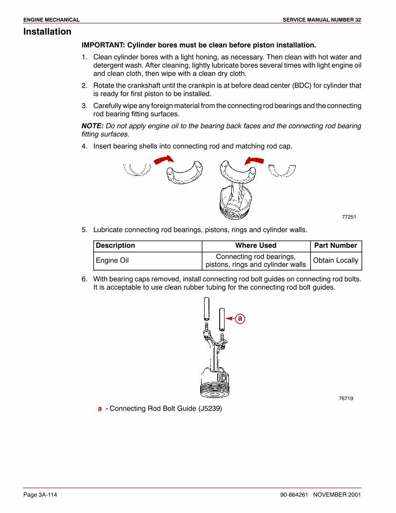
ENGINE MECHANICAL SERVICE MANUAL NUMBER 32
Page 3A-114 90-864261 NOVEMBER 2001
InstallationIMPORTANT: Cylinder bores must be clean before piston installation.
1. Clean cylinder bores with a light honing, as necessary. Then clean with hot water anddetergent wash. After cleaning, lightly lubricate bores several times with light engine oiland clean cloth, then wipe with a clean dry cloth.
2. Rotate the crankshaft until the crankpin is at before dead center (BDC) for cylinder thatis ready for first piston to be installed.
3. Carefullywipe any foreignmaterial from the connecting rodbearingsand theconnectingrod bearing fitting surfaces.
NOTE: Do not apply engine oil to the bearing back faces and the connecting rod bearingfitting surfaces.
4. Insert bearing shells into connecting rod and matching rod cap.
77251
5. Lubricate connecting rod bearings, pistons, rings and cylinder walls.
Description Where Used Part Number
Engine Oil Connecting rod bearings,pistons, rings and cylinder walls Obtain Locally
6. With bearing caps removed, install connecting rod bolt guides on connecting rod bolts.It is acceptable to use clean rubber tubing for the connecting rod bolt guides.
76719
a
a - Connecting Rod Bolt Guide (J5239)
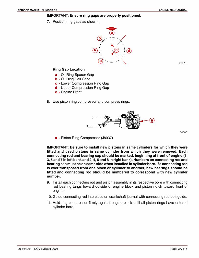
ENGINE MECHANICALSERVICE MANUAL NUMBER 32
90-864261 NOVEMBER 2001 Page 3A-115
IMPORTANT: Ensure ring gaps are properly positioned.
7. Position ring gaps as shown.
72373
b
b
c da
e
Ring Gap Locationa -Oil Ring Spacer Gapb -Oil Ring Rail Gapsc - Lower Compression Ring Gapd - Upper Compression Ring Gape - Engine Front
8. Use piston ring compressor and compress rings.
00000
a
a - Piston Ring Compressor (J8037)
IMPORTANT: Be sure to install new pistons in same cylinders for which they werefitted and used pistons in same cylinder from which they were removed. Eachconnecting rod and bearing cap should be marked, beginning at front of engine (1,3, 5 and 7 in left bank and 2, 4, 6 and 8 in right bank). Numbers on connecting rod andbearing capmust beonsamesidewhen installed in cylinder bore. If a connecting rodis ever transposed from one block or cylinder to another, new bearings should befitted and connecting rod should be numbered to correspond with new cylindernumber.
9. Install each connecting rod and piston assembly in its respective bore with connectingrod bearing tangs toward outside of engine block and piston notch toward front ofengine.
10. Guide connecting rod into place on crankshaft journal with connecting rod bolt guide.
11. Hold ring compressor firmly against engine block until all piston rings have enteredcylinder bore.
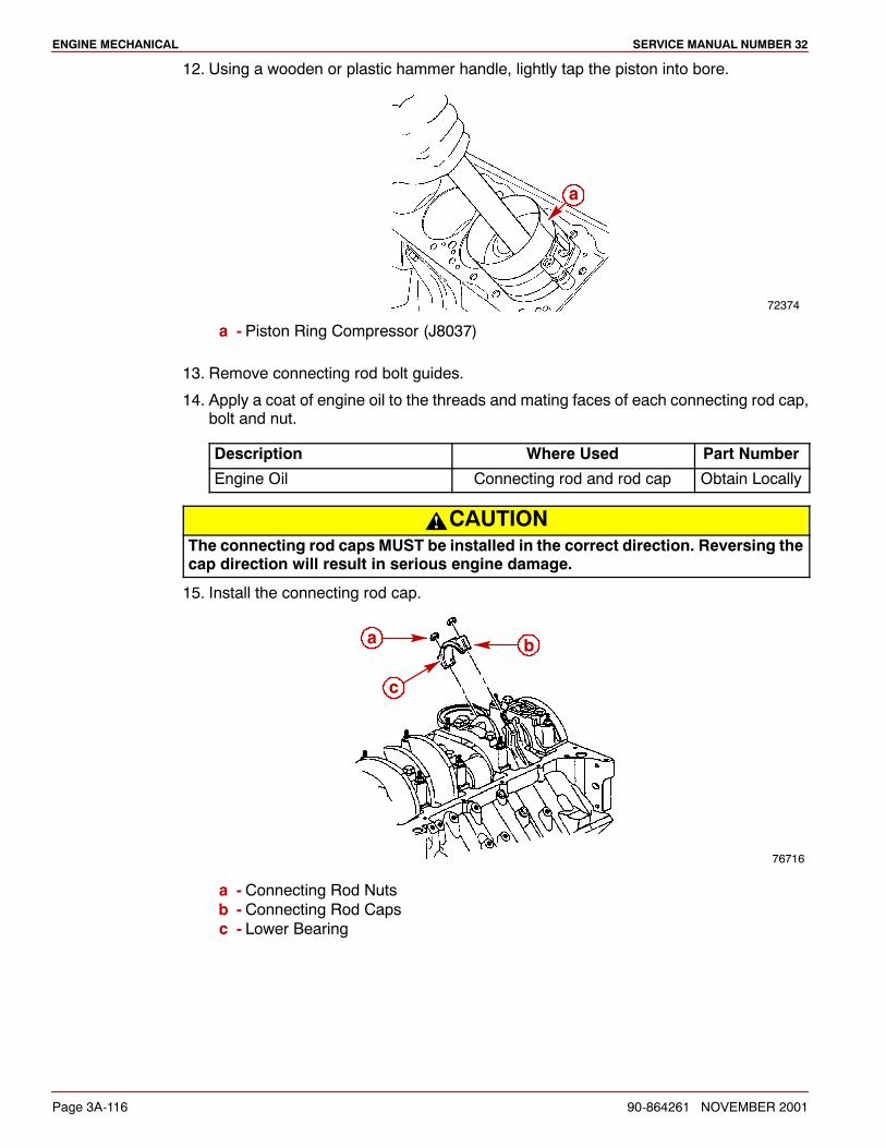
ENGINE MECHANICAL SERVICE MANUAL NUMBER 32
Page 3A-116 90-864261 NOVEMBER 2001
12. Using a wooden or plastic hammer handle, lightly tap the piston into bore.
72374
a
a - Piston Ring Compressor (J8037)
13. Remove connecting rod bolt guides.
14. Apply a coat of engine oil to the threads and mating faces of each connecting rod cap,bolt and nut.
Description Where Used Part Number
Engine Oil Connecting rod and rod cap Obtain Locally
CAUTIONThe connecting rod caps MUST be installed in the correct direction. Reversing thecap direction will result in serious engine damage.
15. Install the connecting rod cap.
76716
a
c
b
a - Connecting Rod Nutsb - Connecting Rod Capsc - Lower Bearing
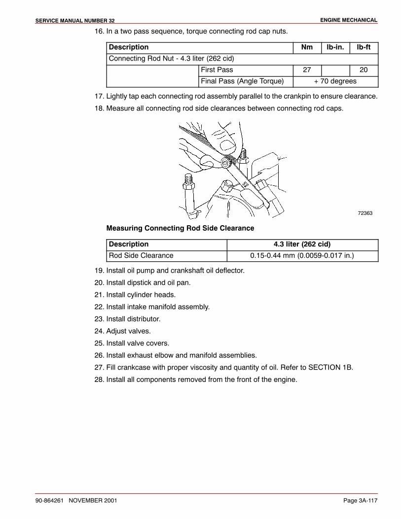
ENGINE MECHANICALSERVICE MANUAL NUMBER 32
90-864261 NOVEMBER 2001 Page 3A-117
16. In a two pass sequence, torque connecting rod cap nuts.
Description Nm lb-in. lb-ft
Connecting Rod Nut - 4.3 liter (262 cid)
First Pass 27 20
Final Pass (Angle Torque) + 70 degrees
17. Lightly tap each connecting rod assembly parallel to the crankpin to ensure clearance.
18. Measure all connecting rod side clearances between connecting rod caps.
72363
Measuring Connecting Rod Side Clearance
Description 4.3 liter (262 cid)
Rod Side Clearance 0.15-0.44 mm (0.0059-0.017 in.)
19. Install oil pump and crankshaft oil deflector.
20. Install dipstick and oil pan.
21. Install cylinder heads.
22. Install intake manifold assembly.
23. Install distributor.
24. Adjust valves.
25. Install valve covers.
26. Install exhaust elbow and manifold assemblies.
27. Fill crankcase with proper viscosity and quantity of oil. Refer to SECTION 1B.
28. Install all components removed from the front of the engine.
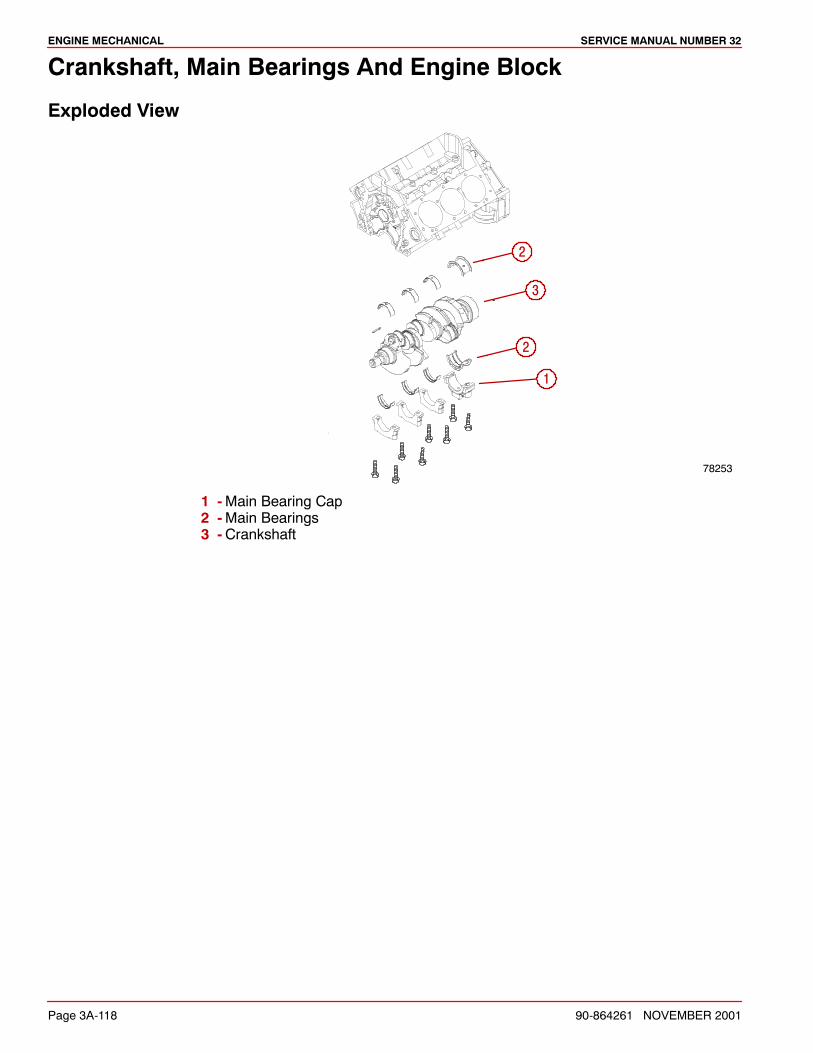
ENGINE MECHANICAL SERVICE MANUAL NUMBER 32
Page 3A-118 90-864261 NOVEMBER 2001
Crankshaft, Main Bearings And Engine Block
Exploded View
78253
2
1
3
2
1 -Main Bearing Cap2 -Main Bearings3 -Crankshaft

ENGINE MECHANICALSERVICE MANUAL NUMBER 32
90-864261 NOVEMBER 2001 Page 3A-119
Removal
NOTICE
If only themain bearings are being serviced refer to Installation - BearingsWithoutCrankshaft Removed.
1. Remove sterndrive unit.
2. Remove engine from boat.
3. Drain crankcase oil.
4. Remove starter.
5. Remove flywheel housing.
6. Remove coupler / drive plate.
7. Remove flywheel.
8. Remove belt.
9. Remove water circulating pump.
10. Remove crankshaft pulley and crankshaft balancer.
11. Remove spark plugs.
12. Remove dipstick tube and oil pan.
13. Remove crankshaft oil deflector and oil pump.
14. Remove crankshaft position sensor. Discard O-ring seal.
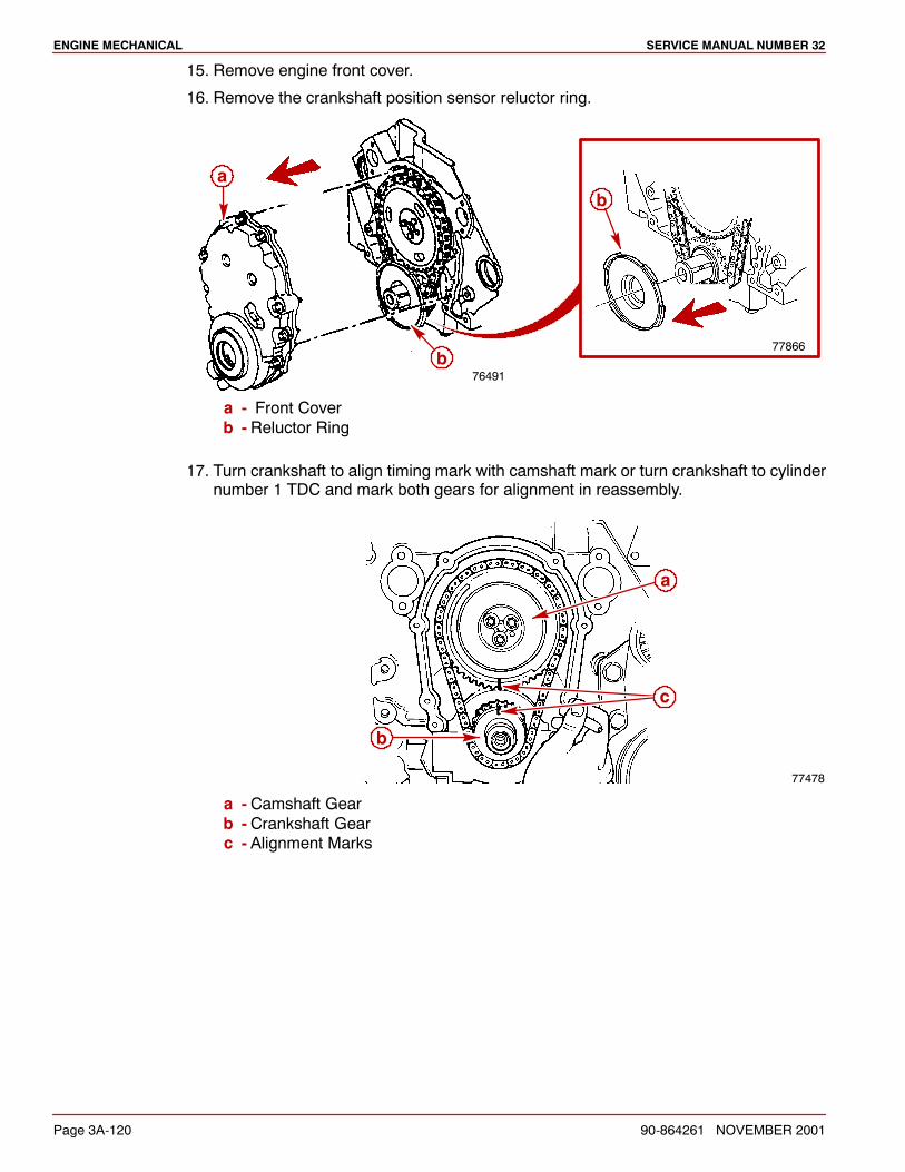
ENGINE MECHANICAL SERVICE MANUAL NUMBER 32
Page 3A-120 90-864261 NOVEMBER 2001
15. Remove engine front cover.
16. Remove the crankshaft position sensor reluctor ring.
76491b
a
77866
b
a - Front Coverb - Reluctor Ring
17. Turn crankshaft to align timing mark with camshaft mark or turn crankshaft to cylindernumber 1 TDC and mark both gears for alignment in reassembly.
77478
a
b
c
a - Camshaft Gearb - Crankshaft Gearc - Alignment Marks
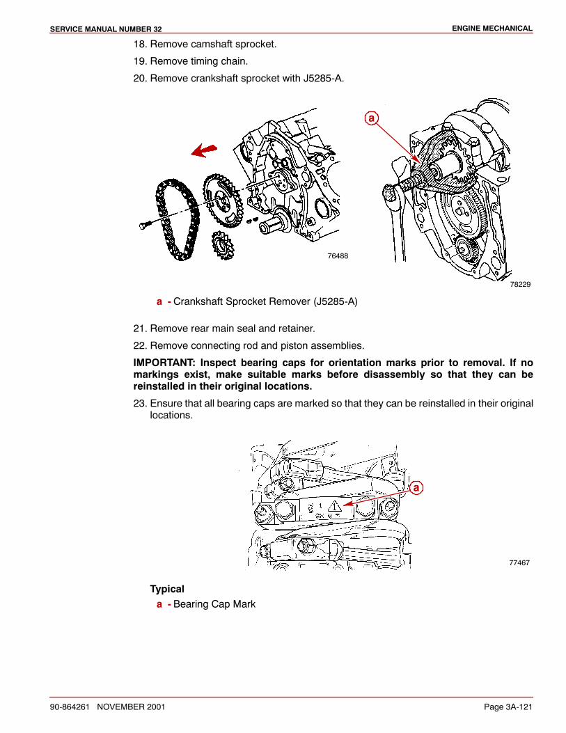
ENGINE MECHANICALSERVICE MANUAL NUMBER 32
90-864261 NOVEMBER 2001 Page 3A-121
18. Remove camshaft sprocket.
19. Remove timing chain.
20. Remove crankshaft sprocket with J5285-A.
78229
76488
a
a - Crankshaft Sprocket Remover (J5285-A)
21. Remove rear main seal and retainer.
22. Remove connecting rod and piston assemblies.
IMPORTANT: Inspect bearing caps for orientation marks prior to removal. If nomarkings exist, make suitable marks before disassembly so that they can bereinstalled in their original locations.
23. Ensure that all bearing caps are marked so that they can be reinstalled in their originallocations.
77467
a
Typicala - Bearing Cap Mark
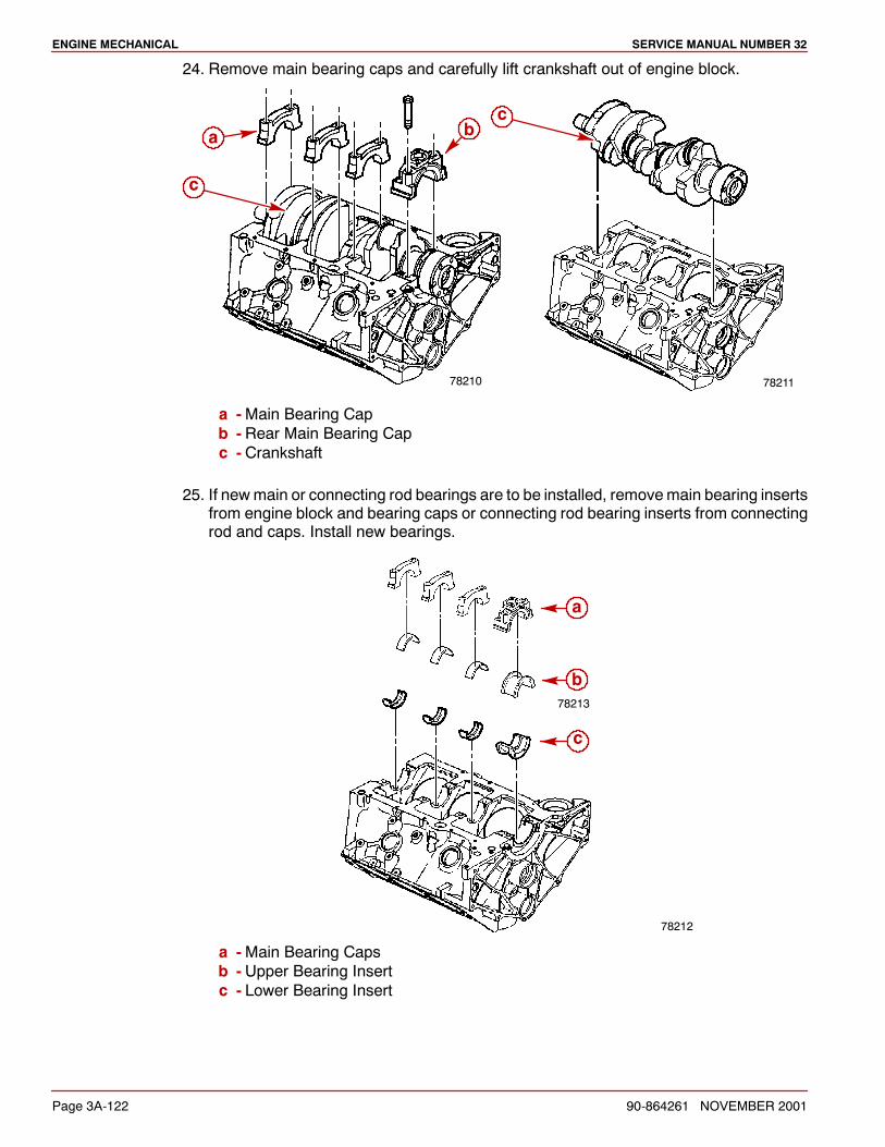
ENGINE MECHANICAL SERVICE MANUAL NUMBER 32
Page 3A-122 90-864261 NOVEMBER 2001
24. Remove main bearing caps and carefully lift crankshaft out of engine block.
78210
a b
c
78211
c
a -Main Bearing Capb - Rear Main Bearing Capc - Crankshaft
25. If newmain or connecting rod bearings are to be installed, removemain bearing insertsfrom engine block and bearing caps or connecting rod bearing inserts from connectingrod and caps. Install new bearings.
78212
78213
a
b
c
a -Main Bearing Capsb - Upper Bearing Insertc - Lower Bearing Insert
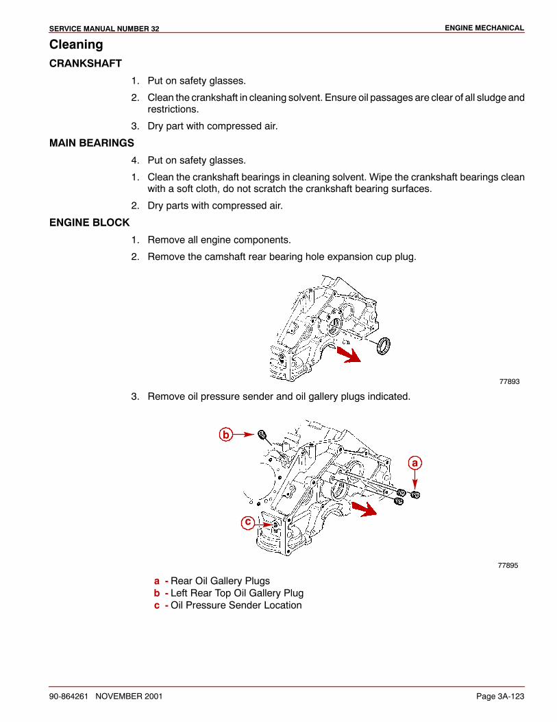
ENGINE MECHANICALSERVICE MANUAL NUMBER 32
90-864261 NOVEMBER 2001 Page 3A-123
CleaningCRANKSHAFT
1. Put on safety glasses.
2. Clean the crankshaft in cleaning solvent. Ensure oil passages are clear of all sludge andrestrictions.
3. Dry part with compressed air.
MAIN BEARINGS
4. Put on safety glasses.
1. Clean the crankshaft bearings in cleaning solvent. Wipe the crankshaft bearings cleanwith a soft cloth, do not scratch the crankshaft bearing surfaces.
2. Dry parts with compressed air.
ENGINE BLOCK
1. Remove all engine components.
2. Remove the camshaft rear bearing hole expansion cup plug.
77893
3. Remove oil pressure sender and oil gallery plugs indicated.
77895
a
b
c
a - Rear Oil Gallery Plugsb - Left Rear Top Oil Gallery Plugc -Oil Pressure Sender Location
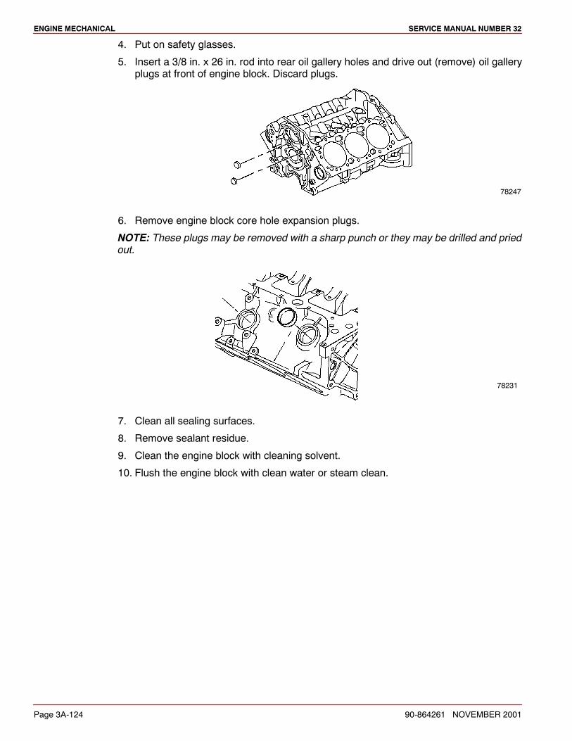
ENGINE MECHANICAL SERVICE MANUAL NUMBER 32
Page 3A-124 90-864261 NOVEMBER 2001
4. Put on safety glasses.
5. Insert a 3/8 in. x 26 in. rod into rear oil gallery holes and drive out (remove) oil galleryplugs at front of engine block. Discard plugs.
78247
6. Remove engine block core hole expansion plugs.
NOTE: These plugs may be removed with a sharp punch or they may be drilled and priedout.
78231
7. Clean all sealing surfaces.
8. Remove sealant residue.
9. Clean the engine block with cleaning solvent.
10. Flush the engine block with clean water or steam clean.
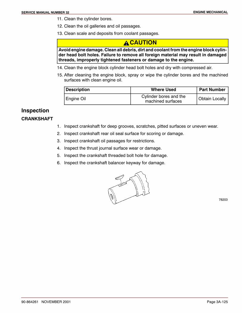
ENGINE MECHANICALSERVICE MANUAL NUMBER 32
90-864261 NOVEMBER 2001 Page 3A-125
11. Clean the cylinder bores.
12. Clean the oil galleries and oil passages.
13. Clean scale and deposits from coolant passages.
CAUTIONAvoidenginedamage.Clean all debris, dirt and coolant from theengineblockcylin-der head bolt holes. Failure to remove all foreign material may result in damagedthreads, improperly tightened fasteners or damage to the engine.
14. Clean the engine block cylinder head bolt holes and dry with compressed air.
15. After cleaning the engine block, spray or wipe the cylinder bores and the machinedsurfaces with clean engine oil.
Description Where Used Part Number
Engine Oil Cylinder bores and themachined surfaces Obtain Locally
InspectionCRANKSHAFT
1. Inspect crankshaft for deep grooves, scratches, pitted surfaces or uneven wear.
2. Inspect crankshaft rear oil seal surface for scoring or damage.
3. Inspect crankshaft oil passages for restrictions.
4. Inspect the thrust journal surface wear or damage.
5. Inspect the crankshaft threaded bolt hole for damage.
6. Inspect the crankshaft balancer keyway for damage.
78203
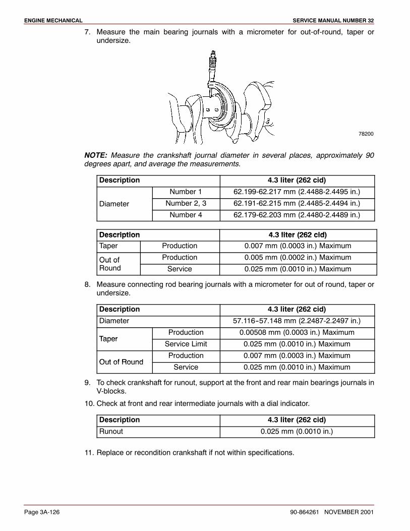
ENGINE MECHANICAL SERVICE MANUAL NUMBER 32
Page 3A-126 90-864261 NOVEMBER 2001
7. Measure the main bearing journals with a micrometer for out-of-round, taper orundersize.
78200
NOTE: Measure the crankshaft journal diameter in several places, approximately 90degrees apart, and average the measurements.
Description 4.3 liter (262 cid)
Number 1 62.199-62.217 mm (2.4488-2.4495 in.)
Diameter Number 2, 3 62.191-62.215 mm (2.4485-2.4494 in.)
Number 4 62.179-62.203 mm (2.4480-2.4489 in.)
Description 4 3 liter (262 cid)Description 4.3 liter (262 cid)Taper Production 0.007 mm (0.0003 in.) Maximum
Out of Production 0.005 mm (0.0002 in.) MaximumOut ofRound Service 0.025 mm (0.0010 in.) Maximum
8. Measure connecting rod bearing journals with a micrometer for out of round, taper orundersize.
Description 4.3 liter (262 cid)
Diameter 57.116--57.148 mm (2.2487-2.2497 in.)
TaperProduction 0.00508 mm (0.0003 in.) Maximum
TaperService Limit 0.025 mm (0.0010 in.) Maximum
Out of RoundProduction 0.007 mm (0.0003 in.) Maximum
Out of RoundService 0.025 mm (0.0010 in.) Maximum
9. To check crankshaft for runout, support at the front and rear main bearings journals inV-blocks.
10. Check at front and rear intermediate journals with a dial indicator.
Description 4.3 liter (262 cid)
Runout 0.025 mm (0.0010 in.)
11. Replace or recondition crankshaft if not within specifications.
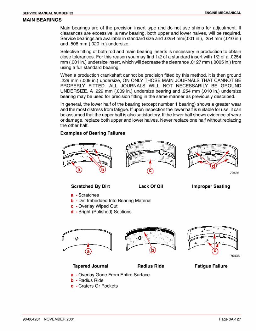
ENGINE MECHANICALSERVICE MANUAL NUMBER 32
90-864261 NOVEMBER 2001 Page 3A-127
MAIN BEARINGS
Main bearings are of the precision insert type and do not use shims for adjustment. Ifclearances are excessive, a new bearing, both upper and lower halves, will be required.Service bearings are available in standard size and .0254 mm(.001 in.), .254 mm (.010 in.)and .508 mm (.020 in.) undersize.
Selective fitting of both rod and main bearing inserts is necessary in production to obtainclose tolerances. For this reason you may find 1/2 of a standard insert with 1/2 of a .0254mm (.001 in.) undersize insert, which will decrease the clearance .0127mm (.0005 in.) fromusing a full standard bearing.
When a production crankshaft cannot be precision fitted by this method, it is then ground.229 mm (.009 in.) undersize, ON ONLY THOSE MAIN JOURNALS THAT CANNOT BEPROPERLY FITTED. ALL JOURNALS WILL NOT NECESSARILY BE GROUNDUNDERSIZE. A .229 mm (.009 in.) undersize bearing and .254 mm (.010 in.) undersizebearing may be used for precision fitting in the same manner as previously described.
In general, the lower half of the bearing (except number 1 bearing) shows a greater wearand themost distress from fatigue. If upon inspection the lower half is suitable for use, it canbe assumed that the upper half is also satisfactory. If the lower half shows evidence of wearor damage, replace both upper and lower halves. Never replace one half without replacingthe other half.
Examples of Bearing Failures
70436a b c
d
Scratched By Dirt Lack Of Oil Improper Seating
a - Scratchesb - Dirt Imbedded Into Bearing Materialc -Overlay Wiped Outd - Bright (Polished) Sections
70436ca b
Tapered Journal Radius Ride Fatigue Failure
a -Overlay Gone From Entire Surfaceb - Radius Ridec - Craters Or Pockets
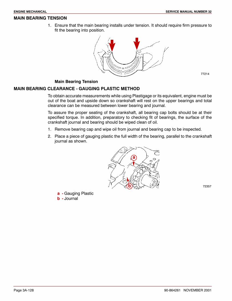
ENGINE MECHANICAL SERVICE MANUAL NUMBER 32
Page 3A-128 90-864261 NOVEMBER 2001
MAIN BEARING TENSION
1. Ensure that the main bearing installs under tension. It should require firm pressure tofit the bearing into position.
77214
Main Bearing Tension
MAIN BEARING CLEARANCE - GAUGING PLASTIC METHOD
To obtain accurate measurements while using Plastigage or its equivalent, engine must beout of the boat and upside down so crankshaft will rest on the upper bearings and totalclearance can be measured between lower bearing and journal.
To assure the proper seating of the crankshaft, all bearing cap bolts should be at theirspecified torque. In addition, preparatory to checking fit of bearings, the surface of thecrankshaft journal and bearing should be wiped clean of oil.
1. Remove bearing cap and wipe oil from journal and bearing cap to be inspected.
2. Place a piece of gauging plastic the full width of the bearing, parallel to the crankshaftjournal as shown.
72357
a
b
a -Gauging Plasticb - Journal
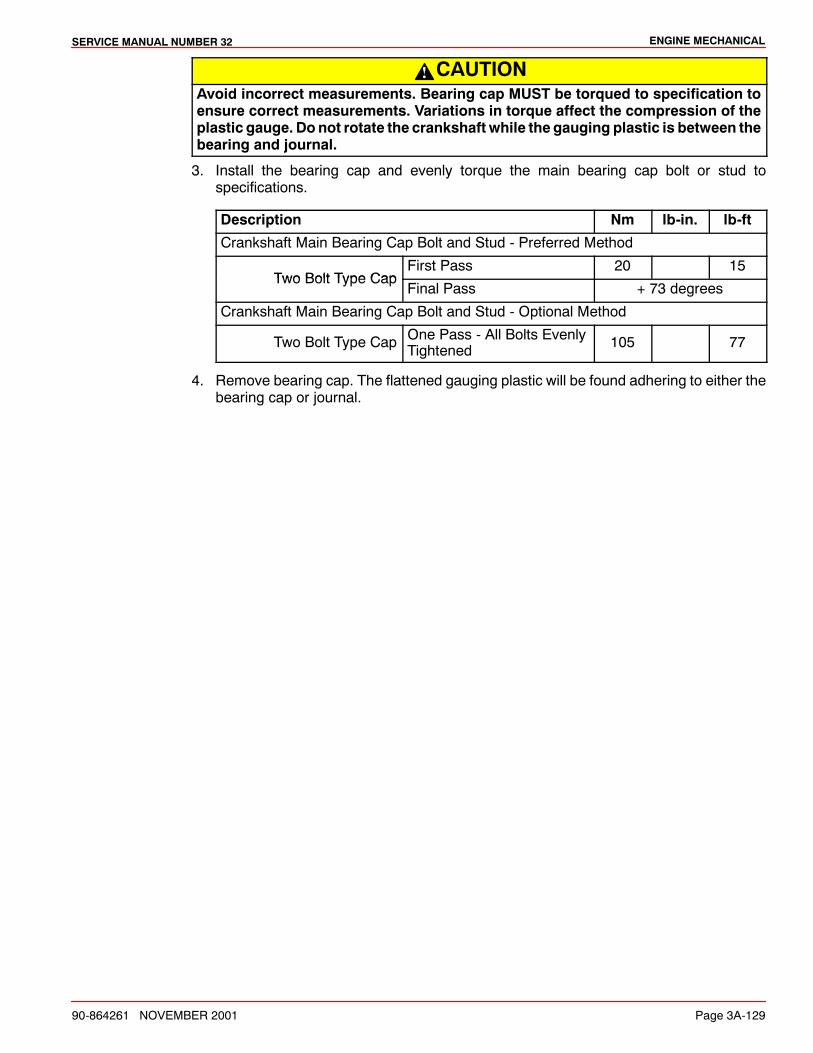
ENGINE MECHANICALSERVICE MANUAL NUMBER 32
90-864261 NOVEMBER 2001 Page 3A-129
CAUTIONAvoid incorrect measurements. Bearing cap MUST be torqued to specification toensure correct measurements. Variations in torque affect the compression of theplastic gauge. Do not rotate the crankshaft while the gauging plastic is between thebearing and journal.
3. Install the bearing cap and evenly torque the main bearing cap bolt or stud tospecifications.
Description Nm lb-in. lb-ft
Crankshaft Main Bearing Cap Bolt and Stud - Preferred Method
Two Bolt Type CapFirst Pass 20 15
Two Bolt Type CapFinal Pass + 73 degrees
Crankshaft Main Bearing Cap Bolt and Stud - Optional Method
Two Bolt Type Cap One Pass - All Bolts EvenlyTightened 105 77
4. Remove bearing cap. The flattened gauging plastic will be found adhering to either thebearing cap or journal.
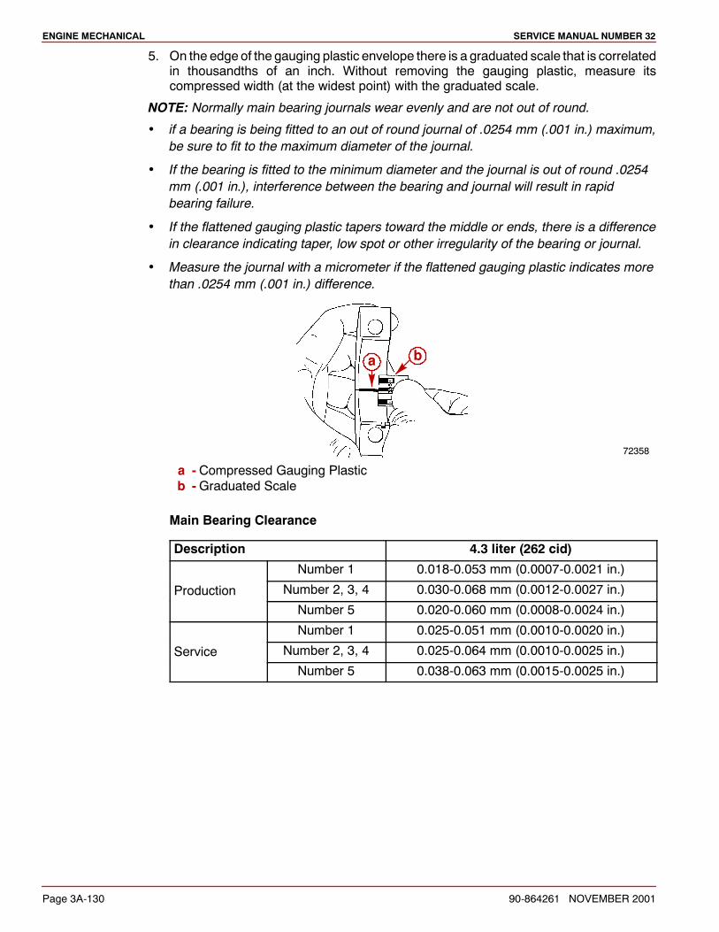
ENGINE MECHANICAL SERVICE MANUAL NUMBER 32
Page 3A-130 90-864261 NOVEMBER 2001
5. On the edge of the gauging plastic envelope there is a graduated scale that is correlatedin thousandths of an inch. Without removing the gauging plastic, measure itscompressed width (at the widest point) with the graduated scale.
NOTE: Normally main bearing journals wear evenly and are not out of round.
if a bearing is being fitted to an out of round journal of .0254 mm (.001 in.) maximum,be sure to fit to the maximum diameter of the journal.
If the bearing is fitted to the minimum diameter and the journal is out of round .0254mm (.001 in.), interference between the bearing and journal will result in rapidbearing failure.
If the flattened gauging plastic tapers toward the middle or ends, there is a differencein clearance indicating taper, low spot or other irregularity of the bearing or journal.
Measure the journal with a micrometer if the flattened gauging plastic indicates morethan .0254 mm (.001 in.) difference.
72358
a b
a - Compressed Gauging Plasticb -Graduated Scale
Main Bearing Clearance
Description 4.3 liter (262 cid)
Number 1 0.018-0.053 mm (0.0007-0.0021 in.)
Production Number 2, 3, 4 0.030-0.068 mm (0.0012-0.0027 in.)
Number 5 0.020-0.060 mm (0.0008-0.0024 in.)
Number 1 0.025-0.051 mm (0.0010-0.0020 in.)
Service Number 2, 3, 4 0.025-0.064 mm (0.0010-0.0025 in.)
Number 5 0.038-0.063 mm (0.0015-0.0025 in.)
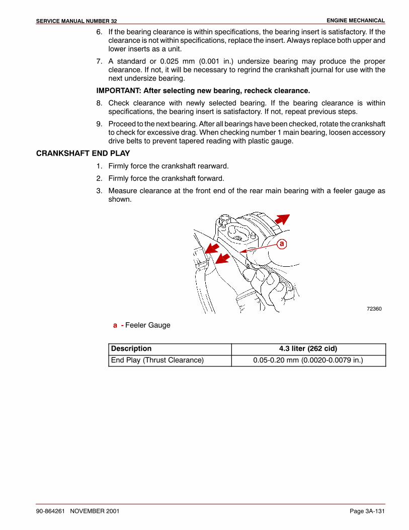
ENGINE MECHANICALSERVICE MANUAL NUMBER 32
90-864261 NOVEMBER 2001 Page 3A-131
6. If the bearing clearance is within specifications, the bearing insert is satisfactory. If theclearance is not within specifications, replace the insert. Always replace both upper andlower inserts as a unit.
7. A standard or 0.025 mm (0.001 in.) undersize bearing may produce the properclearance. If not, it will be necessary to regrind the crankshaft journal for use with thenext undersize bearing.
IMPORTANT: After selecting new bearing, recheck clearance.
8. Check clearance with newly selected bearing. If the bearing clearance is withinspecifications, the bearing insert is satisfactory. If not, repeat previous steps.
9. Proceed to the next bearing. After all bearings havebeen checked, rotate the crankshaftto check for excessive drag. When checking number 1 main bearing, loosen accessorydrive belts to prevent tapered reading with plastic gauge.
CRANKSHAFT END PLAY
1. Firmly force the crankshaft rearward.
2. Firmly force the crankshaft forward.
3. Measure clearance at the front end of the rear main bearing with a feeler gauge asshown.
72360
a
a - Feeler Gauge
Description 4.3 liter (262 cid)
End Play (Thrust Clearance) 0.05-0.20 mm (0.0020-0.0079 in.)

ENGINE MECHANICAL SERVICE MANUAL NUMBER 32
Page 3A-132 90-864261 NOVEMBER 2001
ENGINE BLOCK
1. Inspect the engine block for cracks in coolant jackets.
2. Inspect the cylinder bores for scratches or gouging.
3. Inspect the valve lifter bores for excessive scoring or wear.
4. Inspect the threaded holes, crankshaft bearing caps, bearing bores and engine blockcore hole expansion plug bores for damage.
5. Inspect the engine block, enginemount bosses and crankshaft bearing webs for cracksor damage.
6. Check engine block head gasket surfaces for warp with amachinist’s straight-edge anda feeler gauge. Take measurements diagonally across surfaces (both ways) andstraight down center. If surfaces are warpedmore than specified, engine block must beresurfaced by a machine shop.
72388
a
b
a -Machinist’s Straight-Edgeb - Feeler Gauge
Description 4.3 liter (262 cid)
Cylinder headgasket surfaceflatness
Within An 152 mm(6 in.) Area 0.10 mm (0.0040 in.)
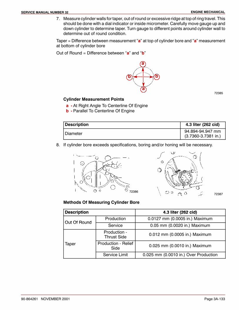
ENGINE MECHANICALSERVICE MANUAL NUMBER 32
90-864261 NOVEMBER 2001 Page 3A-133
7. Measure cylinderwalls for taper, out of roundor excessive ridge at top of ring travel. Thisshould be done with a dial indicator or inside micrometer. Carefully move gauge up anddown cylinder to determine taper. Turn gauge to different points around cylinder wall todetermine out of round condition.
Taper = Difference between measurement “a” at top of cylinder bore and “a” measurementat bottom of cylinder bore
Out of Round = Difference between “a” and “b”
72385
a
bb
a
Cylinder Measurement Pointsa - At Right Angle To Centerline Of Engineb - Parallel To Centerline Of Engine
Description 4.3 liter (262 cid)
Diameter 94.894-94.947 mm(3.7360-3.7381 in.)
8. If cylinder bore exceeds specifications, boring and/or honing will be necessary.
7238672387
Methods Of Measuring Cylinder Bore
Description 4 3 liter (262 cid)Description 4.3 liter (262 cid)
Out Of RoundProduction 0.0127 mm (0.0005 in.) Maximum
Out Of RoundService 0.05 mm (0.0020 in.) Maximum
Production -Thrust Side 0.012 mm (0.0005 in.) Maximum
Taper Production - ReliefSide 0.025 mm (0.0010 in.) Maximum
Service Limit 0.025 mm (0.0010 in.) Over Production
ENGINE MECHANICAL SERVICE MANUAL NUMBER 32
Page 3A-134 90-864261 NOVEMBER 2001
CYLINDER RECONDITIONING
NOTE: Performance of the following operation depends upon engine condition at time ofrepair.
NOTE: If engine block inspection indicates that the block is suitable for continued use, outof round or tapered cylinders can be reconditioned by honing or boring.
1. If cylinders have less than 0.127mm (0.0050 in.) taper or wear, they can be conditionedwith a hone and fitted with high limit standard size piston. A cylinder bore of more than0.127 mm (0.0050 in.) wear or taper may not clean up entirely when fitted to a high limitpiston. To entirely clean up the bore, it will be necessary to bore for an oversize piston.If more than 0.127 mm (0.0050 in.) taper or wear, bore and hone to smallest oversizethat will permit complete resurfacing of all cylinders.
2. When pistons are being fitted and honing is not necessary, cylinder bores may becleaned with a hot water and detergent wash. After cleaning, lightly lubricate cylinderbores with engine oil and a clean cloth and then wipe with a clean dry cloth.
CYLINDER BORING
IMPORTANT: Before using any type of boring bar, file top of engine block to removedirt or burrs. Thispreventsboringbar tilt (theboredcylinderwall is not at right anglesto crankshaft.)
1. File top of engine block to remove dirt and burrs.
2. Measure piston to be fitted with a micrometer, measuring at center of piston skirt andat right angles to piston pin. Bore cylinder to same diameter as piston and hone to givespecified clearance.
NOTE: Hone cylinders as outlined under Cylinder Honing and Piston Selection, following.
3. Carefully observe equipment manufacturer’s instructions.
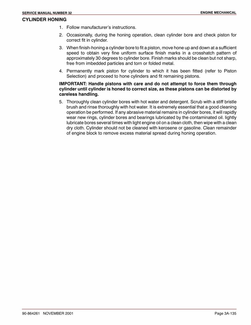
ENGINE MECHANICALSERVICE MANUAL NUMBER 32
90-864261 NOVEMBER 2001 Page 3A-135
CYLINDER HONING
1. Follow manufacturer’s instructions.
2. Occasionally, during the honing operation, clean cylinder bore and check piston forcorrect fit in cylinder.
3. When finish-honing a cylinder bore to fit a piston, move hone up and down at a sufficientspeed to obtain very fine uniform surface finish marks in a crosshatch pattern ofapproximately 30 degrees to cylinder bore. Finishmarks should be clean but not sharp,free from imbedded particles and torn or folded metal.
4. Permanently mark piston for cylinder to which it has been fitted (refer to PistonSelection) and proceed to hone cylinders and fit remaining pistons.
IMPORTANT: Handle pistons with care and do not attempt to force them throughcylinder until cylinder is honed to correct size, as these pistons can be distorted bycareless handling.
5. Thoroughly clean cylinder bores with hot water and detergent. Scrub with a stiff bristlebrush and rinse thoroughly with hot water. It is extremely essential that a good cleaningoperation be performed. If any abrasivematerial remains in cylinder bores, it will rapidlywear new rings, cylinder bores and bearings lubricated by the contaminated oil. lightlylubricate bores several timeswith light engine oil on a clean cloth, thenwipewith a cleandry cloth. Cylinder should not be cleaned with kerosene or gasoline. Clean remainderof engine block to remove excess material spread during honing operation.
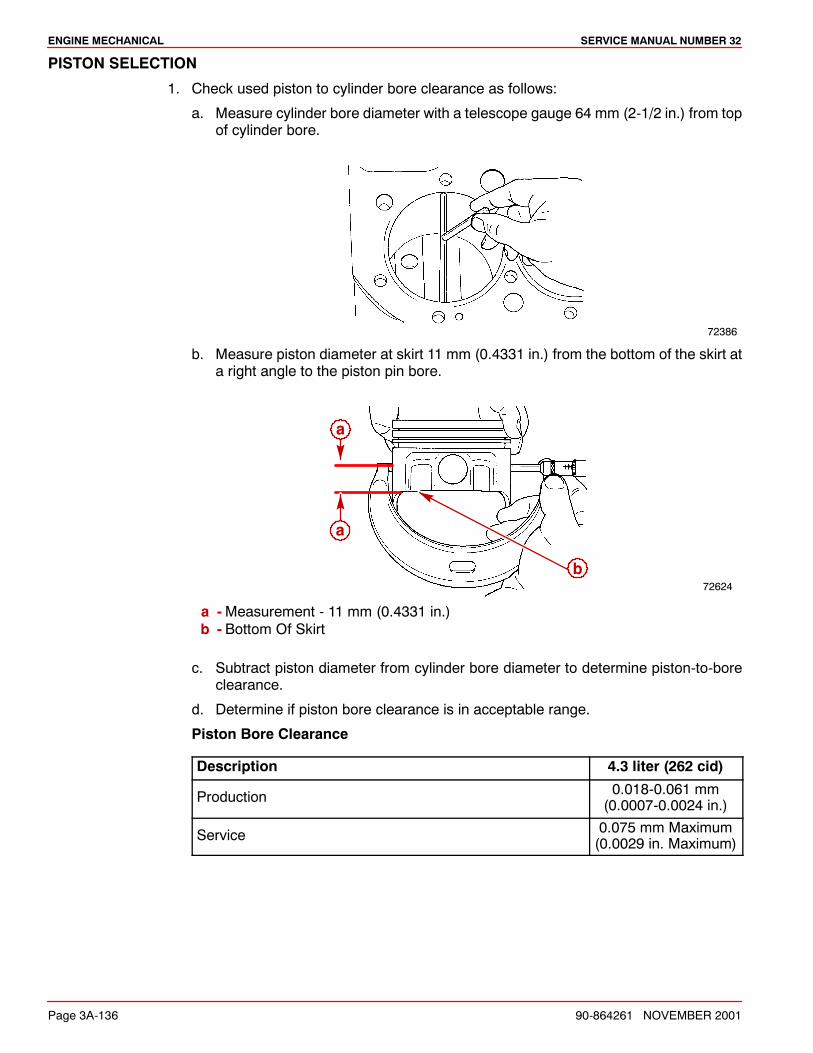
ENGINE MECHANICAL SERVICE MANUAL NUMBER 32
Page 3A-136 90-864261 NOVEMBER 2001
PISTON SELECTION
1. Check used piston to cylinder bore clearance as follows:
a. Measure cylinder bore diameter with a telescope gauge 64 mm (2-1/2 in.) from topof cylinder bore.
72386
b. Measure piston diameter at skirt 11 mm (0.4331 in.) from the bottom of the skirt ata right angle to the piston pin bore.
72624
a
b
a
a -Measurement - 11 mm (0.4331 in.)b - Bottom Of Skirt
c. Subtract piston diameter from cylinder bore diameter to determine piston-to-boreclearance.
d. Determine if piston bore clearance is in acceptable range.
Piston Bore Clearance
Description 4.3 liter (262 cid)
Production 0.018-0.061 mm(0.0007-0.0024 in.)
Service 0.075 mm Maximum(0.0029 in. Maximum)
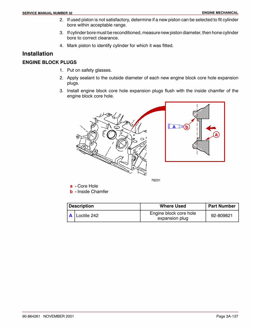
ENGINE MECHANICALSERVICE MANUAL NUMBER 32
90-864261 NOVEMBER 2001 Page 3A-137
2. If used piston is not satisfactory, determine if a new piston can be selected to fit cylinderbore within acceptable range.
3. If cylinder boremust be reconditioned,measurenewpiston diameter, thenhonecylinderbore to correct clearance.
4. Mark piston to identify cylinder for which it was fitted.
InstallationENGINE BLOCK PLUGS
1. Put on safety glasses.
2. Apply sealant to the outside diameter of each new engine block core hole expansionplugs.
3. Install engine block core hole expansion plugs flush with the inside chamfer of theengine block core hole.
ba
78231
A
a - Core Holeb - Inside Chamfer
Description Where Used Part Number
A Loctite 242 Engine block core holeexpansion plug 92-809821
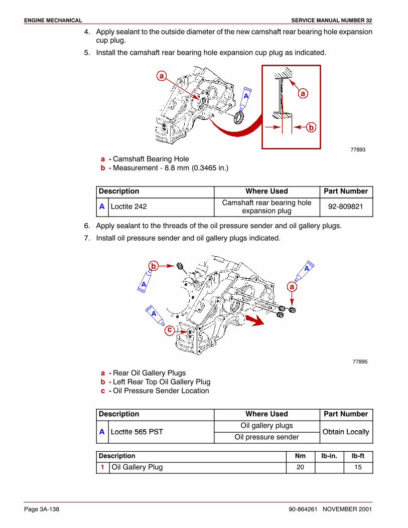
ENGINE MECHANICAL SERVICE MANUAL NUMBER 32
Page 3A-138 90-864261 NOVEMBER 2001
4. Apply sealant to the outside diameter of the new camshaft rear bearing hole expansioncup plug.
5. Install the camshaft rear bearing hole expansion cup plug as indicated.
77893
b
a
aA
a - Camshaft Bearing Holeb -Measurement - 8.8 mm (0.3465 in.)
Description Where Used Part Number
A Loctite 242 Camshaft rear bearing holeexpansion plug 92-809821
6. Apply sealant to the threads of the oil pressure sender and oil gallery plugs.
7. Install oil pressure sender and oil gallery plugs indicated.
77895
a
b
c
A
A
A
a - Rear Oil Gallery Plugsb - Left Rear Top Oil Gallery Plugc -Oil Pressure Sender Location
Description Where Used Part Number
A Loctite 565 PSTOil gallery plugs
Obtain LocallyA Loctite 565 PSTOil pressure sender
Obtain Locally
Description Nm lb-in. lb-ft
1 Oil Gallery Plug 20 15
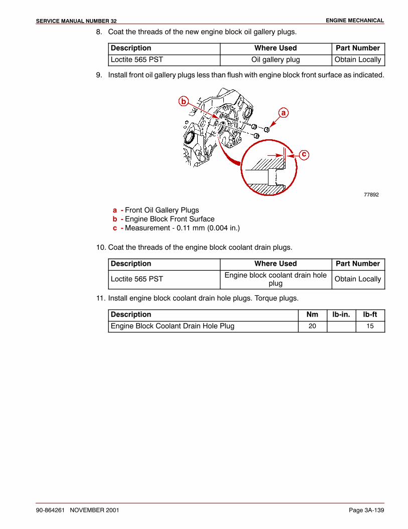
ENGINE MECHANICALSERVICE MANUAL NUMBER 32
90-864261 NOVEMBER 2001 Page 3A-139
8. Coat the threads of the new engine block oil gallery plugs.
Description Where Used Part Number
Loctite 565 PST Oil gallery plug Obtain Locally
9. Install front oil gallery plugs less than flush with engine block front surface as indicated.
c
77892
ab
a - Front Oil Gallery Plugsb - Engine Block Front Surfacec -Measurement - 0.11 mm (0.004 in.)
10. Coat the threads of the engine block coolant drain plugs.
Description Where Used Part Number
Loctite 565 PST Engine block coolant drain holeplug Obtain Locally
11. Install engine block coolant drain hole plugs. Torque plugs.
Description Nm lb-in. lb-ft
Engine Block Coolant Drain Hole Plug 20 15

ENGINE MECHANICAL SERVICE MANUAL NUMBER 32
Page 3A-140 90-864261 NOVEMBER 2001
MAIN BEARINGS - WITHOUT CRANKSHAFT REMOVED
1. Remove the cap on the main bearing requiring replacement.
2. Remove the bearing from the cap.
3. Install the main bearing remover/installer in the oil hole in the crankshaft journal. If thistool is not available, a cotter pin may be bent as shown and used.
72622
b
a
a -Main Bearing Remover/Installer (J8080)b - Cotter Pin
4. Rotate the crankshaft clockwise as viewed from the front of engine. This will roll theupper bearing out of the engine block.
5. Lubricate a new upper bearing.
6. Insert the plain (unnotched) end between the crankshaft and the indented or notchedside of the engine block.
7. Rotate the bearing into place and remove the tool from the oil hole in the crankshaftjournal.
8. Lubricate a new lower bearing and install in bearing cap.
Description Where Used Part Number
Engine Oil Upper Bearing, Lower Bearing Obtain Locally
9. Install themain bearing cap in the original location with themarkings pointing toward thefront of the engine.
77467
a
a - Bearing Cap Marking
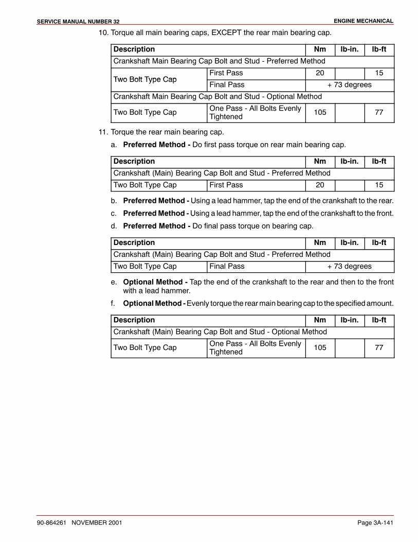
ENGINE MECHANICALSERVICE MANUAL NUMBER 32
90-864261 NOVEMBER 2001 Page 3A-141
10. Torque all main bearing caps, EXCEPT the rear main bearing cap.
Description Nm lb-in. lb-ft
Crankshaft Main Bearing Cap Bolt and Stud - Preferred Method
Two Bolt Type CapFirst Pass 20 15
Two Bolt Type CapFinal Pass + 73 degrees
Crankshaft Main Bearing Cap Bolt and Stud - Optional Method
Two Bolt Type Cap One Pass - All Bolts EvenlyTightened 105 77
11. Torque the rear main bearing cap.
a. Preferred Method - Do first pass torque on rear main bearing cap.
Description Nm lb-in. lb-ft
Crankshaft (Main) Bearing Cap Bolt and Stud - Preferred Method
Two Bolt Type Cap First Pass 20 15
b. PreferredMethod -Using a lead hammer, tap the end of the crankshaft to the rear.
c. PreferredMethod -Using a lead hammer, tap the end of the crankshaft to the front.
d. Preferred Method - Do final pass torque on bearing cap.
Description Nm lb-in. lb-ft
Crankshaft (Main) Bearing Cap Bolt and Stud - Preferred Method
Two Bolt Type Cap Final Pass + 73 degrees
e. Optional Method - Tap the end of the crankshaft to the rear and then to the frontwith a lead hammer.
f. OptionalMethod -Evenly torque the rearmain bearing cap to the specifiedamount.
Description Nm lb-in. lb-ft
Crankshaft (Main) Bearing Cap Bolt and Stud - Optional Method
Two Bolt Type Cap One Pass - All Bolts EvenlyTightened 105 77
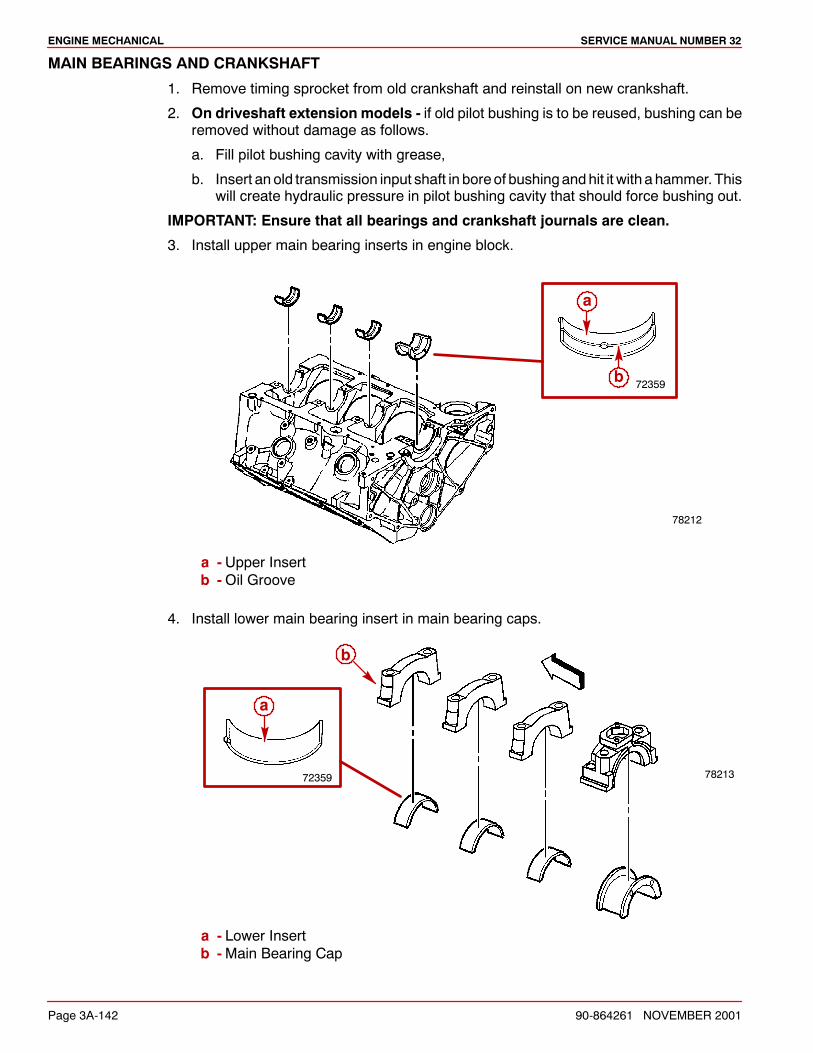
ENGINE MECHANICAL SERVICE MANUAL NUMBER 32
Page 3A-142 90-864261 NOVEMBER 2001
MAIN BEARINGS AND CRANKSHAFT
1. Remove timing sprocket from old crankshaft and reinstall on new crankshaft.
2. On driveshaft extension models - if old pilot bushing is to be reused, bushing can beremoved without damage as follows.
a. Fill pilot bushing cavity with grease,
b. Insert an old transmission input shaft in boreof bushingandhit it with a hammer. Thiswill create hydraulic pressure in pilot bushing cavity that should force bushing out.
IMPORTANT: Ensure that all bearings and crankshaft journals are clean.
3. Install upper main bearing inserts in engine block.
78212
72359b
a
a - Upper Insertb -Oil Groove
4. Install lower main bearing insert in main bearing caps.
78213
a
b
72359
a - Lower Insertb -Main Bearing Cap

ENGINE MECHANICALSERVICE MANUAL NUMBER 32
90-864261 NOVEMBER 2001 Page 3A-143
5. Carefully lower crankshaft into place. Be careful not to damage bearing surfaces.
78211
6. Install main bearing caps in original location with markings pointing toward front ofengine.
77467
a
c
7. Check clearance of each main bearing, following procedure outlined under Inspection- Main Bearing Clearance.
8. When bearing clearances meet specifications, lubricate the main bearings andcrankshaft bearing journals.
Description Where Used Part Number
Engine Oil Main bearings and crankshaftbearing journals Obtain Locally
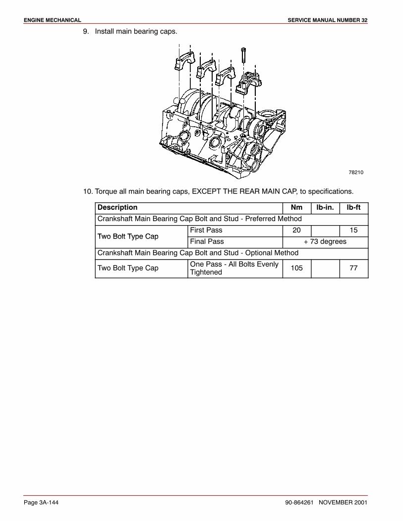
ENGINE MECHANICAL SERVICE MANUAL NUMBER 32
Page 3A-144 90-864261 NOVEMBER 2001
9. Install main bearing caps.
78210
10. Torque all main bearing caps, EXCEPT THE REAR MAIN CAP, to specifications.
Description Nm lb-in. lb-ft
Crankshaft Main Bearing Cap Bolt and Stud - Preferred Method
Two Bolt Type CapFirst Pass 20 15
Two Bolt Type CapFinal Pass + 73 degrees
Crankshaft Main Bearing Cap Bolt and Stud - Optional Method
Two Bolt Type Cap One Pass - All Bolts EvenlyTightened 105 77
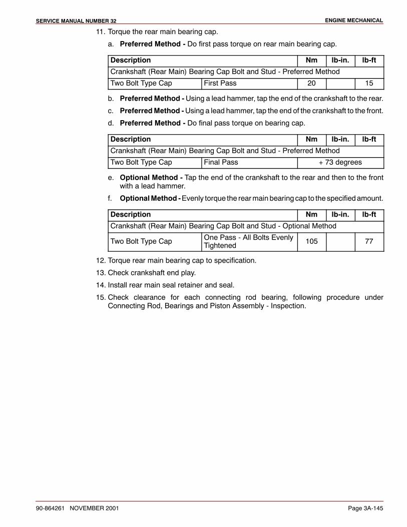
ENGINE MECHANICALSERVICE MANUAL NUMBER 32
90-864261 NOVEMBER 2001 Page 3A-145
11. Torque the rear main bearing cap.
a. Preferred Method - Do first pass torque on rear main bearing cap.
Description Nm lb-in. lb-ft
Crankshaft (Rear Main) Bearing Cap Bolt and Stud - Preferred Method
Two Bolt Type Cap First Pass 20 15
b. PreferredMethod -Using a lead hammer, tap the end of the crankshaft to the rear.
c. PreferredMethod -Using a lead hammer, tap the end of the crankshaft to the front.
d. Preferred Method - Do final pass torque on bearing cap.
Description Nm lb-in. lb-ft
Crankshaft (Rear Main) Bearing Cap Bolt and Stud - Preferred Method
Two Bolt Type Cap Final Pass + 73 degrees
e. Optional Method - Tap the end of the crankshaft to the rear and then to the frontwith a lead hammer.
f. OptionalMethod -Evenly torque the rearmain bearing cap to the specifiedamount.
Description Nm lb-in. lb-ft
Crankshaft (Rear Main) Bearing Cap Bolt and Stud - Optional Method
Two Bolt Type Cap One Pass - All Bolts EvenlyTightened 105 77
12. Torque rear main bearing cap to specification.
13. Check crankshaft end play.
14. Install rear main seal retainer and seal.
15. Check clearance for each connecting rod bearing, following procedure underConnecting Rod, Bearings and Piston Assembly - Inspection.
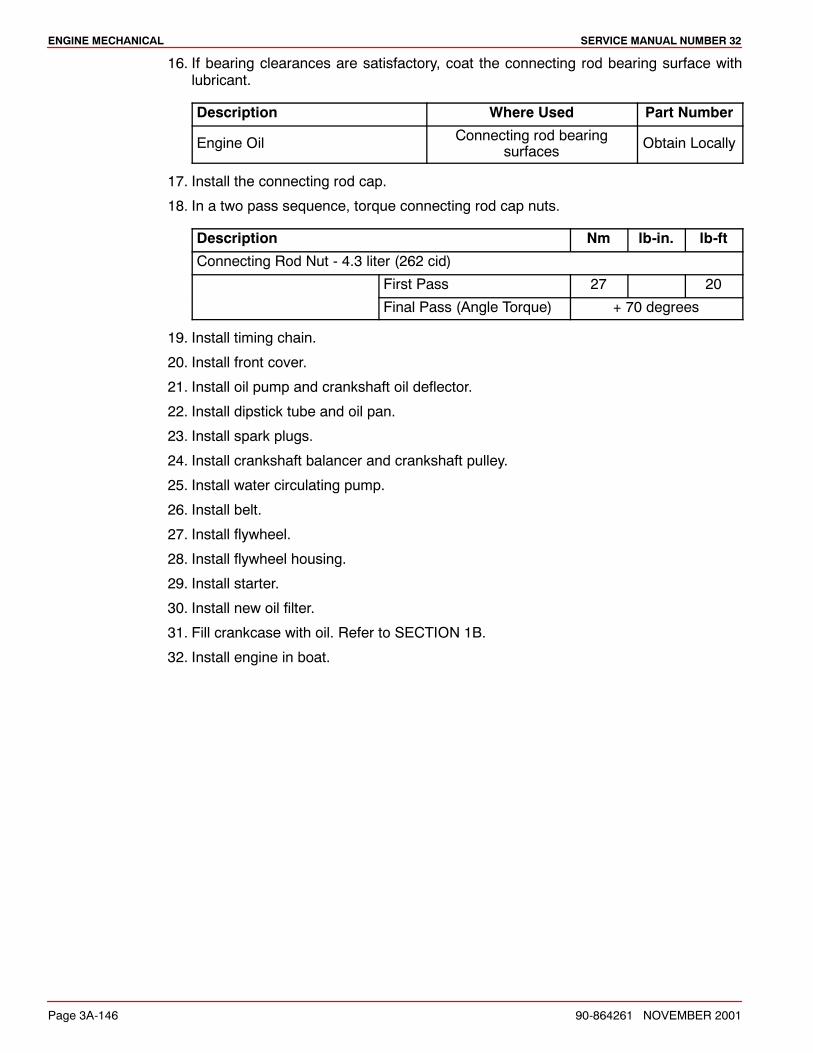
ENGINE MECHANICAL SERVICE MANUAL NUMBER 32
Page 3A-146 90-864261 NOVEMBER 2001
16. If bearing clearances are satisfactory, coat the connecting rod bearing surface withlubricant.
Description Where Used Part Number
Engine Oil Connecting rod bearingsurfaces Obtain Locally
17. Install the connecting rod cap.
18. In a two pass sequence, torque connecting rod cap nuts.
Description Nm lb-in. lb-ft
Connecting Rod Nut - 4.3 liter (262 cid)
First Pass 27 20
Final Pass (Angle Torque) + 70 degrees
19. Install timing chain.
20. Install front cover.
21. Install oil pump and crankshaft oil deflector.
22. Install dipstick tube and oil pan.
23. Install spark plugs.
24. Install crankshaft balancer and crankshaft pulley.
25. Install water circulating pump.
26. Install belt.
27. Install flywheel.
28. Install flywheel housing.
29. Install starter.
30. Install new oil filter.
31. Fill crankcase with oil. Refer to SECTION 1B.
32. Install engine in boat.
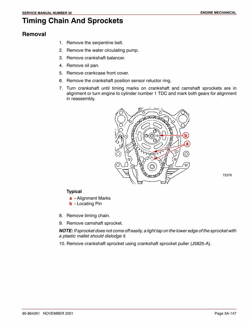
ENGINE MECHANICALSERVICE MANUAL NUMBER 32
90-864261 NOVEMBER 2001 Page 3A-147
Timing Chain And Sprockets
Removal1. Remove the serpentine belt.
2. Remove the water circulating pump.
3. Remove crankshaft balancer.
4. Remove oil pan.
5. Remove crankcase front cover.
6. Remove the crankshaft position sensor reluctor ring.
7. Turn crankshaft until timing marks on crankshaft and camshaft sprockets are inalignment or turn engine to cylinder number 1 TDC and mark both gears for alignmentin reassembly.
72376
b
a
Typicala - Alignment Marksb - Locating Pin
8. Remove timing chain.
9. Remove camshaft sprocket.
NOTE: If sprocket does not comeoff easily, a light tap on the lower edge of the sprocket witha plastic mallet should dislodge it.
10. Remove crankshaft sprocket using crankshaft sprocket puller (J5825-A).
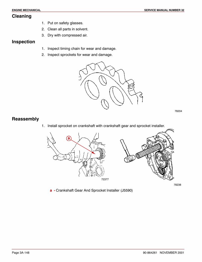
ENGINE MECHANICAL SERVICE MANUAL NUMBER 32
Page 3A-148 90-864261 NOVEMBER 2001
Cleaning1. Put on safety glasses.
2. Clean all parts in solvent.
3. Dry with compressed air.
Inspection1. Inspect timing chain for wear and damage.
2. Inspect sprockets for wear and damage.
78204
Reassembly1. Install sprocket on crankshaft with crankshaft gear and sprocket installer.
72377
a
78238
a - Crankshaft Gear And Sprocket Installer (J5590)
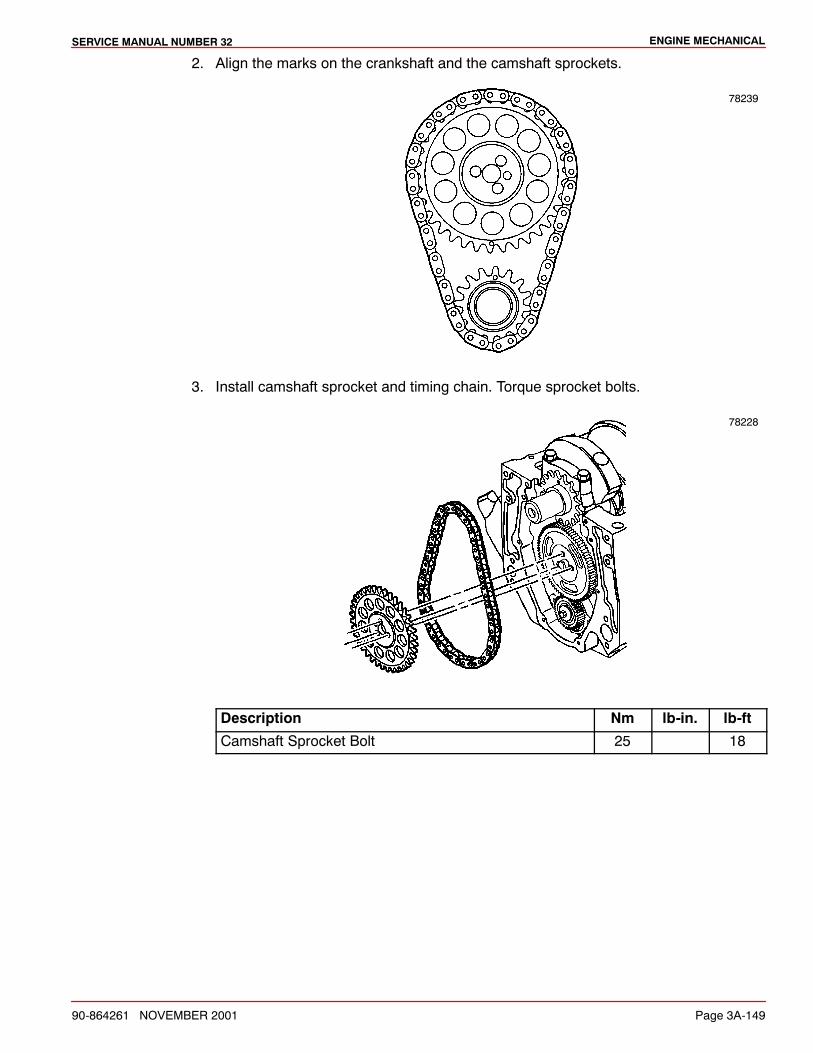
ENGINE MECHANICALSERVICE MANUAL NUMBER 32
90-864261 NOVEMBER 2001 Page 3A-149
2. Align the marks on the crankshaft and the camshaft sprockets.
78239
3. Install camshaft sprocket and timing chain. Torque sprocket bolts.
78228
Description Nm lb-in. lb-ft
Camshaft Sprocket Bolt 25 18
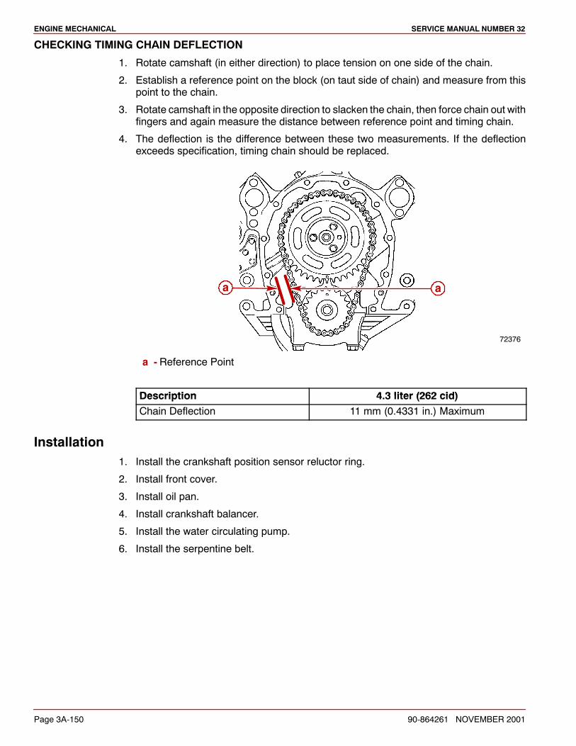
ENGINE MECHANICAL SERVICE MANUAL NUMBER 32
Page 3A-150 90-864261 NOVEMBER 2001
CHECKING TIMING CHAIN DEFLECTION
1. Rotate camshaft (in either direction) to place tension on one side of the chain.
2. Establish a reference point on the block (on taut side of chain) and measure from thispoint to the chain.
3. Rotate camshaft in the opposite direction to slacken the chain, then force chain out withfingers and again measure the distance between reference point and timing chain.
4. The deflection is the difference between these two measurements. If the deflectionexceeds specification, timing chain should be replaced.
72376
a a
a - Reference Point
Description 4 3 liter (262 cid)Description 4.3 liter (262 cid)Chain Deflection 11 mm (0.4331 in.) Maximum
Installation1. Install the crankshaft position sensor reluctor ring.
2. Install front cover.
3. Install oil pan.
4. Install crankshaft balancer.
5. Install the water circulating pump.
6. Install the serpentine belt.
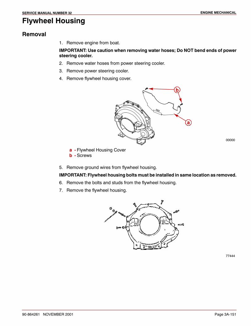
ENGINE MECHANICALSERVICE MANUAL NUMBER 32
90-864261 NOVEMBER 2001 Page 3A-151
Flywheel Housing
Removal1. Remove engine from boat.
IMPORTANT: Use caution when removing water hoses; Do NOT bend ends of powersteering cooler.
2. Remove water hoses from power steering cooler.
3. Remove power steering cooler.
4. Remove flywheel housing cover.
00000
a
b
a - Flywheel Housing Coverb - Screws
5. Remove ground wires from flywheel housing.
IMPORTANT: Flywheel housing boltsmust be installed in same location as removed.
6. Remove the bolts and studs from the flywheel housing.
7. Remove the flywheel housing.
77444
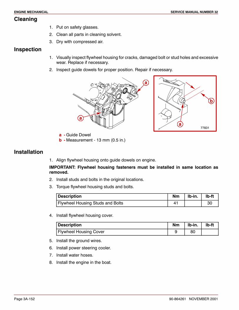
ENGINE MECHANICAL SERVICE MANUAL NUMBER 32
Page 3A-152 90-864261 NOVEMBER 2001
Cleaning1. Put on safety glasses.
2. Clean all parts in cleaning solvent.
3. Dry with compressed air.
Inspection1. Visually inspect flywheel housing for cracks, damaged bolt or stud holes and excessive
wear. Replace if necessary.
2. Inspect guide dowels for proper position. Repair if necessary.
a
77831
b
aa
a -Guide Dowelb -Measurement - 13 mm (0.5 in.)
Installation1. Align flywheel housing onto guide dowels on engine.
IMPORTANT: Flywheel housing fasteners must be installed in same location asremoved.
2. Install studs and bolts in the original locations.
3. Torque flywheel housing studs and bolts.
Description Nm lb-in. lb-ft
Flywheel Housing Studs and Bolts 41 30
4. Install flywheel housing cover.
Description Nm lb-in. lb-ft
Flywheel Housing Cover 9 80
5. Install the ground wires.
6. Install power steering cooler.
7. Install water hoses.
8. Install the engine in the boat.
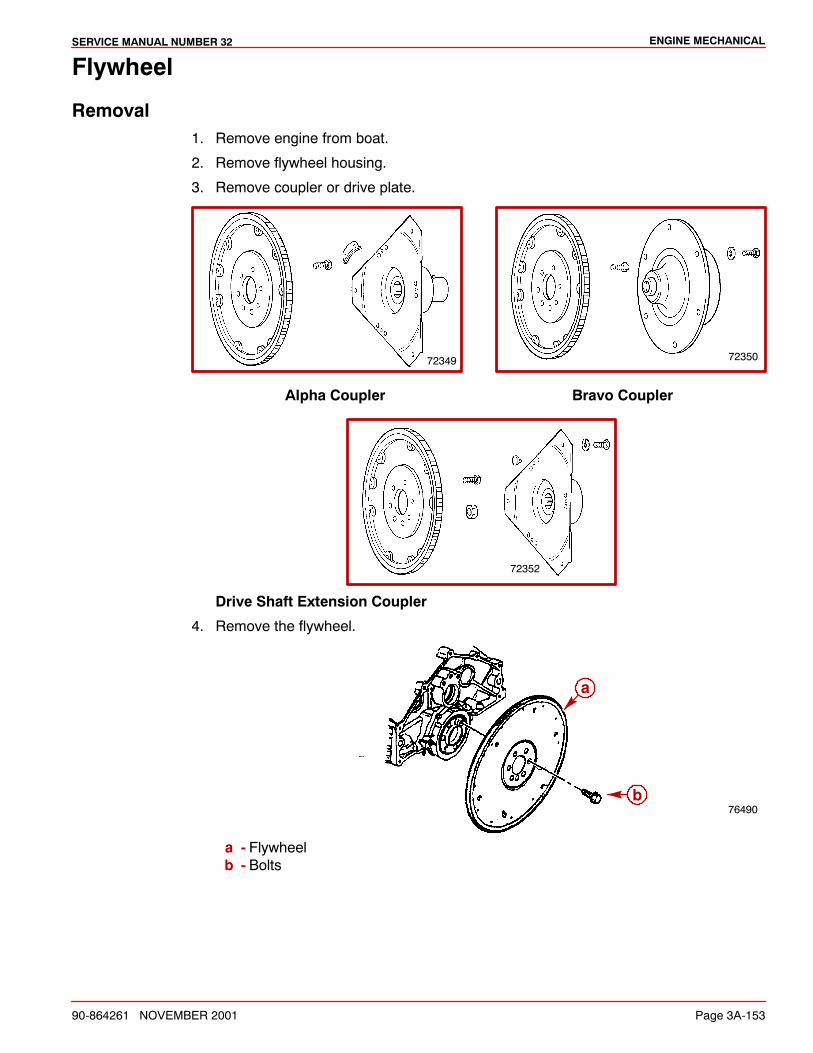
ENGINE MECHANICALSERVICE MANUAL NUMBER 32
90-864261 NOVEMBER 2001 Page 3A-153
Flywheel
Removal1. Remove engine from boat.
2. Remove flywheel housing.
3. Remove coupler or drive plate.
72349 72350
Alpha Coupler Bravo Coupler
72352
Drive Shaft Extension Coupler
4. Remove the flywheel.
76490
a
b
a - Flywheelb - Bolts
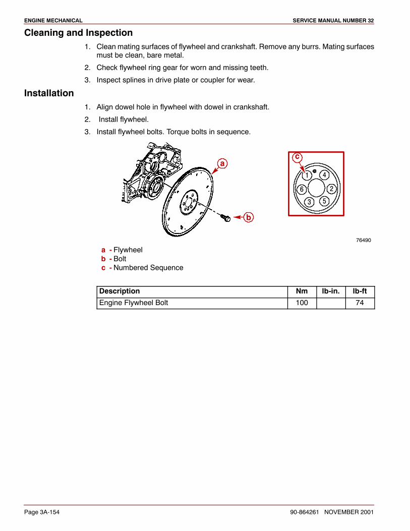
ENGINE MECHANICAL SERVICE MANUAL NUMBER 32
Page 3A-154 90-864261 NOVEMBER 2001
Cleaning and Inspection1. Clean mating surfaces of flywheel and crankshaft. Remove any burrs. Mating surfaces
must be clean, bare metal.
2. Check flywheel ring gear for worn and missing teeth.
3. Inspect splines in drive plate or coupler for wear.
Installation1. Align dowel hole in flywheel with dowel in crankshaft.
2. Install flywheel.
3. Install flywheel bolts. Torque bolts in sequence.
76490
a
b
1
2
3
4
5
6
c
a - Flywheelb - Boltc - Numbered Sequence
Description Nm lb-in. lb-ft
Engine Flywheel Bolt 100 74
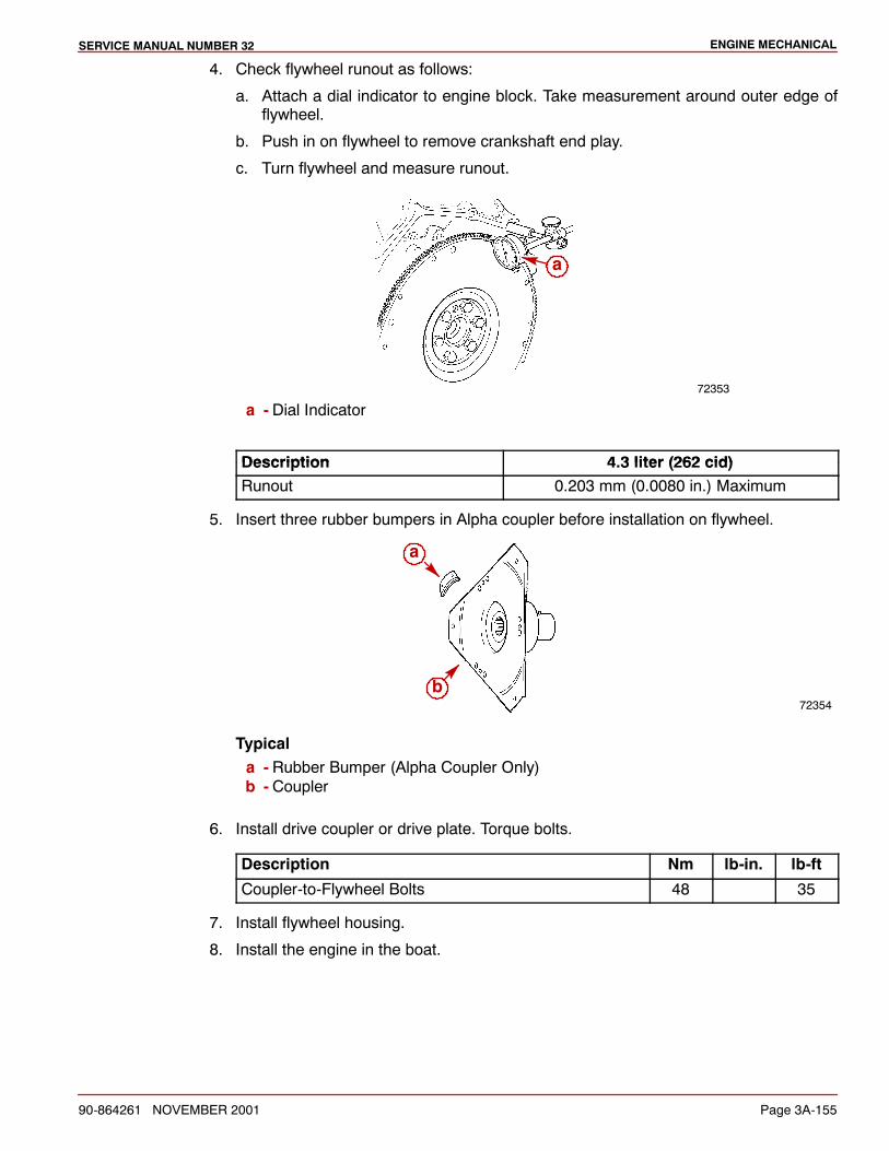
ENGINE MECHANICALSERVICE MANUAL NUMBER 32
90-864261 NOVEMBER 2001 Page 3A-155
4. Check flywheel runout as follows:
a. Attach a dial indicator to engine block. Take measurement around outer edge offlywheel.
b. Push in on flywheel to remove crankshaft end play.
c. Turn flywheel and measure runout.
72353
a
a - Dial Indicator
Description 4 3 liter (262 cid)Description 4.3 liter (262 cid)Runout 0.203 mm (0.0080 in.) Maximum
5. Insert three rubber bumpers in Alpha coupler before installation on flywheel.
72354
a
b
Typicala - Rubber Bumper (Alpha Coupler Only)b - Coupler
6. Install drive coupler or drive plate. Torque bolts.
Description Nm lb-in. lb-ft
Coupler-to-Flywheel Bolts 48 35
7. Install flywheel housing.
8. Install the engine in the boat.
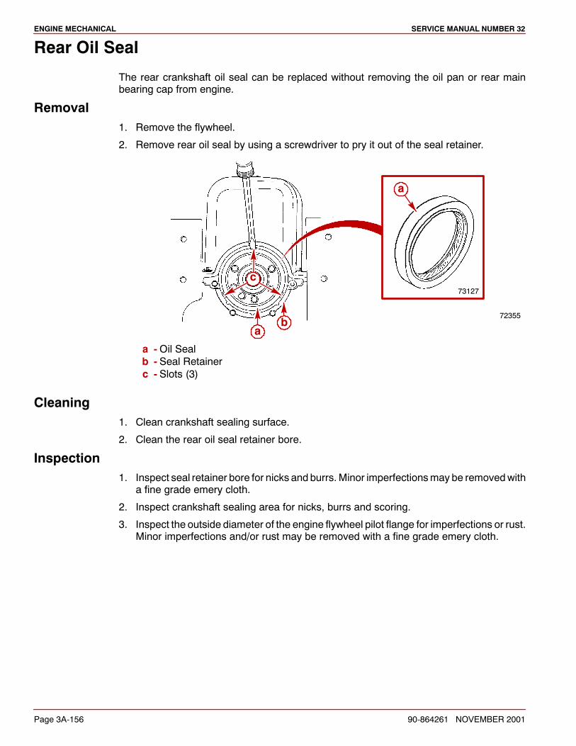
ENGINE MECHANICAL SERVICE MANUAL NUMBER 32
Page 3A-156 90-864261 NOVEMBER 2001
Rear Oil Seal
The rear crankshaft oil seal can be replaced without removing the oil pan or rear mainbearing cap from engine.
Removal1. Remove the flywheel.
2. Remove rear oil seal by using a screwdriver to pry it out of the seal retainer.
72355
c
ab
73127
a
a -Oil Sealb - Seal Retainerc - Slots (3)
Cleaning1. Clean crankshaft sealing surface.
2. Clean the rear oil seal retainer bore.
Inspection1. Inspect seal retainer bore for nicks and burrs.Minor imperfectionsmay be removedwith
a fine grade emery cloth.
2. Inspect crankshaft sealing area for nicks, burrs and scoring.
3. Inspect the outside diameter of the engine flywheel pilot flange for imperfections or rust.Minor imperfections and/or rust may be removed with a fine grade emery cloth.
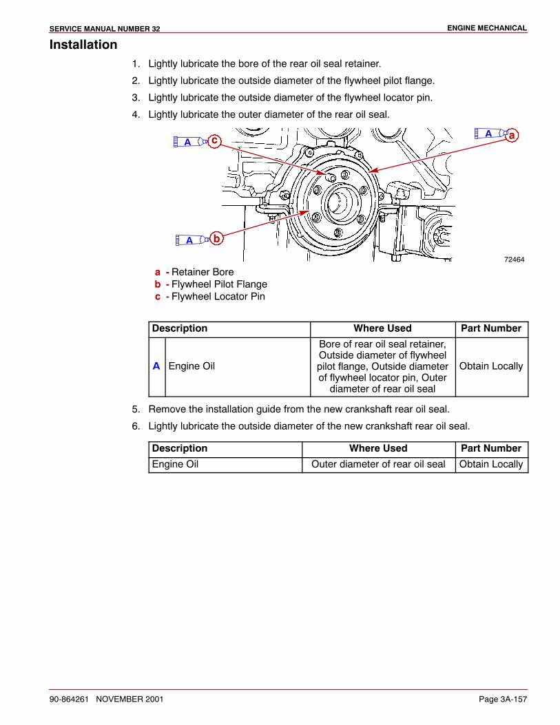
ENGINE MECHANICALSERVICE MANUAL NUMBER 32
90-864261 NOVEMBER 2001 Page 3A-157
Installation1. Lightly lubricate the bore of the rear oil seal retainer.
2. Lightly lubricate the outside diameter of the flywheel pilot flange.
3. Lightly lubricate the outside diameter of the flywheel locator pin.
4. Lightly lubricate the outer diameter of the rear oil seal.
72464
a
b
cA
A
A
a - Retainer Boreb - Flywheel Pilot Flangec - Flywheel Locator Pin
Description Where Used Part Number
A Engine Oil
Bore of rear oil seal retainer,Outside diameter of flywheelpilot flange, Outside diameterof flywheel locator pin, Outerdiameter of rear oil seal
Obtain Locally
5. Remove the installation guide from the new crankshaft rear oil seal.
6. Lightly lubricate the outside diameter of the new crankshaft rear oil seal.
Description Where Used Part Number
Engine Oil Outer diameter of rear oil seal Obtain Locally
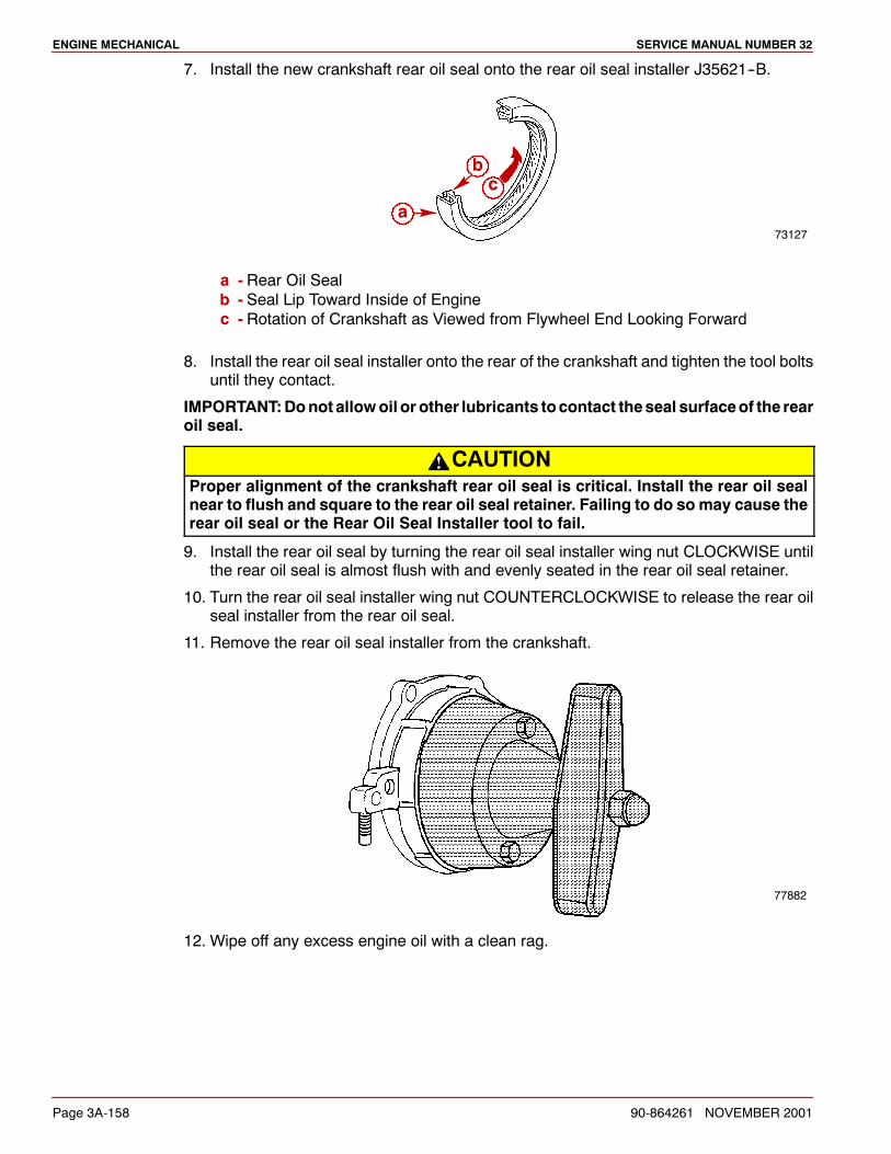
ENGINE MECHANICAL SERVICE MANUAL NUMBER 32
Page 3A-158 90-864261 NOVEMBER 2001
7. Install the new crankshaft rear oil seal onto the rear oil seal installer J35621--B.
73127
c
a
b
a - Rear Oil Sealb - Seal Lip Toward Inside of Enginec - Rotation of Crankshaft as Viewed from Flywheel End Looking Forward
8. Install the rear oil seal installer onto the rear of the crankshaft and tighten the tool boltsuntil they contact.
IMPORTANT:Donot allowoil or other lubricants tocontact theseal surfaceof the rearoil seal.
CAUTIONProper alignment of the crankshaft rear oil seal is critical. Install the rear oil sealnear to flush and square to the rear oil seal retainer. Failing to do somay cause therear oil seal or the Rear Oil Seal Installer tool to fail.
9. Install the rear oil seal by turning the rear oil seal installer wing nut CLOCKWISE untilthe rear oil seal is almost flush with and evenly seated in the rear oil seal retainer.
10. Turn the rear oil seal installer wing nut COUNTERCLOCKWISE to release the rear oilseal installer from the rear oil seal.
11. Remove the rear oil seal installer from the crankshaft.
77882
12. Wipe off any excess engine oil with a clean rag.
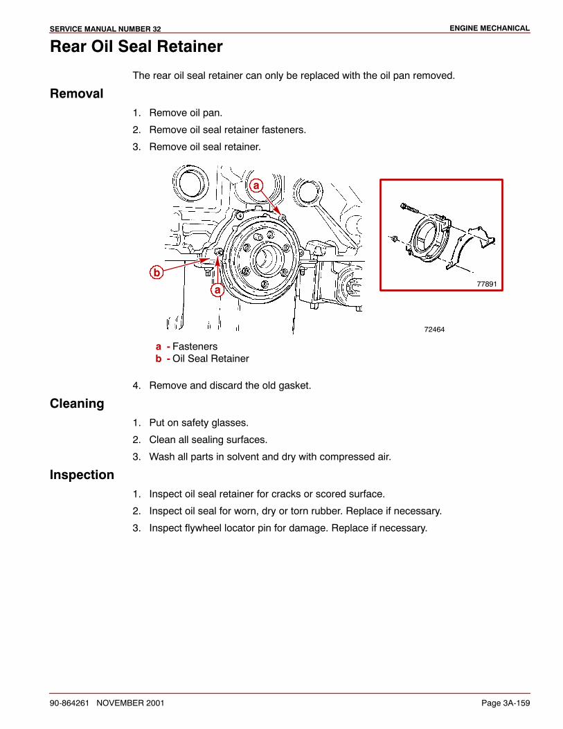
ENGINE MECHANICALSERVICE MANUAL NUMBER 32
90-864261 NOVEMBER 2001 Page 3A-159
Rear Oil Seal Retainer
The rear oil seal retainer can only be replaced with the oil pan removed.
Removal1. Remove oil pan.
2. Remove oil seal retainer fasteners.
3. Remove oil seal retainer.
72464
a
b
a77891
a - Fastenersb -Oil Seal Retainer
4. Remove and discard the old gasket.
Cleaning1. Put on safety glasses.
2. Clean all sealing surfaces.
3. Wash all parts in solvent and dry with compressed air.
Inspection1. Inspect oil seal retainer for cracks or scored surface.
2. Inspect oil seal for worn, dry or torn rubber. Replace if necessary.
3. Inspect flywheel locator pin for damage. Replace if necessary.
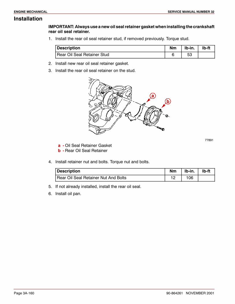
ENGINE MECHANICAL SERVICE MANUAL NUMBER 32
Page 3A-160 90-864261 NOVEMBER 2001
InstallationIMPORTANT:Alwaysuseanewoil seal retainergasketwhen installing thecrankshaftrear oil seal retainer.
1. Install the rear oil seal retainer stud, if removed previously. Torque stud.
Description Nm lb-in. lb-ft
Rear Oil Seal Retainer Stud 6 53
2. Install new rear oil seal retainer gasket.
3. Install the rear oil seal retainer on the stud.
77891
ab
a -Oil Seal Retainer Gasketb - Rear Oil Seal Retainer
4. Install retainer nut and bolts. Torque nut and bolts.
Description Nm lb-in. lb-ft
Rear Oil Seal Retainer Nut And Bolts 12 106
5. If not already installed, install the rear oil seal.
6. Install oil pan.

ENGINE MECHANICALSERVICE MANUAL NUMBER 32
90-864261 NOVEMBER 2001 Page 3A-161
Oil Filter By-Pass Valve and Block Adapter
IMPORTANT: Oil filter by-pass valve and block adapter assembly should beinspected whenever engine is disassembled for major repair or wheneverinadequate oil filtration is suspected.
Exploded View
78162
1
2
3
4
5
6
7
8
9
1 - Filter Adapter Oil Line2 - Fitting/Bushing Oil Line3 - Fitting/Bushing4 -Quad Ring Seal5 -Oil Filter Adapter6 -Seal7 -Bolt8 -Block Adapter And By-Pass Valve9 -Remote Oil Filter and Components
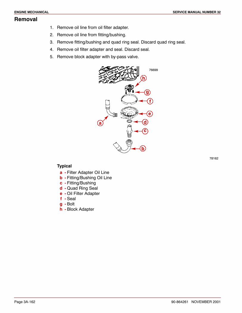
ENGINE MECHANICAL SERVICE MANUAL NUMBER 32
Page 3A-162 90-864261 NOVEMBER 2001
Removal1. Remove oil line from oil filter adapter.
2. Remove oil line from fitting/bushing.
3. Remove fitting/bushing and quad ring seal. Discard quad ring seal.
4. Remove oil filter adapter and seal. Discard seal.
5. Remove block adapter with by-pass valve.
78162
76699
a
b
c
d
e
f
g
h
Typicala - Filter Adapter Oil Lineb - Fitting/Bushing Oil Linec - Fitting/Bushingd -Quad Ring Seale -Oil Filter Adapterf - Sealg - Bolth - Block Adapter
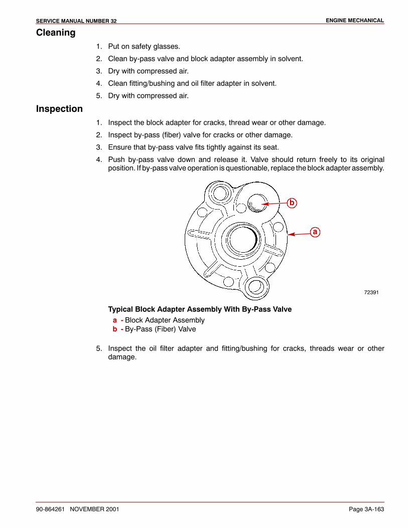
ENGINE MECHANICALSERVICE MANUAL NUMBER 32
90-864261 NOVEMBER 2001 Page 3A-163
Cleaning1. Put on safety glasses.
2. Clean by-pass valve and block adapter assembly in solvent.
3. Dry with compressed air.
4. Clean fitting/bushing and oil filter adapter in solvent.
5. Dry with compressed air.
Inspection1. Inspect the block adapter for cracks, thread wear or other damage.
2. Inspect by-pass (fiber) valve for cracks or other damage.
3. Ensure that by-pass valve fits tightly against its seat.
4. Push by-pass valve down and release it. Valve should return freely to its originalposition. If by-pass valve operation is questionable, replace theblock adapter assembly.
72391
b
a
Typical Block Adapter Assembly With By-Pass Valvea - Block Adapter Assemblyb - By-Pass (Fiber) Valve
5. Inspect the oil filter adapter and fitting/bushing for cracks, threads wear or otherdamage.
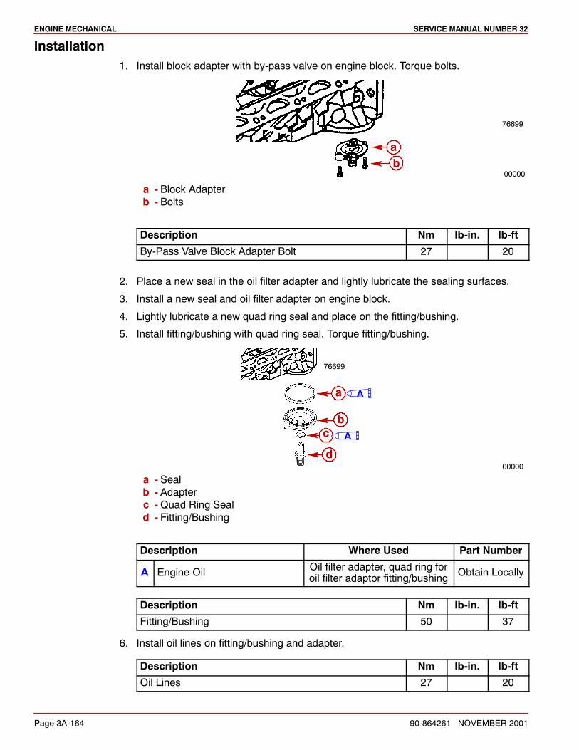
ENGINE MECHANICAL SERVICE MANUAL NUMBER 32
Page 3A-164 90-864261 NOVEMBER 2001
Installation1. Install block adapter with by-pass valve on engine block. Torque bolts.
00000
76699
ab
a - Block Adapterb - Bolts
Description Nm lb-in. lb-ft
By-Pass Valve Block Adapter Bolt 27 20
2. Place a new seal in the oil filter adapter and lightly lubricate the sealing surfaces.
3. Install a new seal and oil filter adapter on engine block.
4. Lightly lubricate a new quad ring seal and place on the fitting/bushing.
5. Install fitting/bushing with quad ring seal. Torque fitting/bushing.
00000
76699
Aa
bc
d
A
a - Sealb - Adapterc -Quad Ring Seald - Fitting/Bushing
Description Where Used Part Number
A Engine Oil Oil filter adapter, quad ring foroil filter adaptor fitting/bushing Obtain Locally
Description Nm lb-in. lb-ft
Fitting/Bushing 50 37
6. Install oil lines on fitting/bushing and adapter.
Description Nm lb-in. lb-ft
Oil Lines 27 20
4A
STARTING SYSTEMSERVICE MANUAL NUMBER 32
90-864261 NOVEMBER 2001 Page 4A-1
ELECTRICAL SYSTEMSection 4A - Starting System
Table of Contents
Identification 4A-2. . . . . . . . . . . . . . . . . . . . . . . . Replacement Parts Warning 4A-2. . . . . . . . . . Precautions 4A-2. . . . . . . . . . . . . . . . . . . . . . . . Typical Starting System Components 4A-3. . Positive Current Flow 4A-4. . . . . . . . . . . . . . . . Battery 4A-4. . . . . . . . . . . . . . . . . . . . . . . . . . . . .
Battery Cable Recommendations 4A-4. . . Delco PG260F1 Starter 4A-5. . . . . . . . . . . . . . Specifications 4A-5. . . . . . . . . . . . . . . . . . . . . . .
Starter Specifications 4A-5. . . . . . . . . . . . . Torque Specifications 4A-5. . . . . . . . . . . . .
Lubricants / Sealants / Adhesives 4A-5. . . . . Description 4A-5. . . . . . . . . . . . . . . . . . . . . . . . .
Testing 4A-6. . . . . . . . . . . . . . . . . . . . . . . . . . Removal 4A-8. . . . . . . . . . . . . . . . . . . . . . . . . . .
Solenoid Switch 4A-9. . . . . . . . . . . . . . . . . . Inspection 4A-9. . . . . . . . . . . . . . . . . . . . . . . . . . Installation 4A-10. . . . . . . . . . . . . . . . . . . . . . . . .
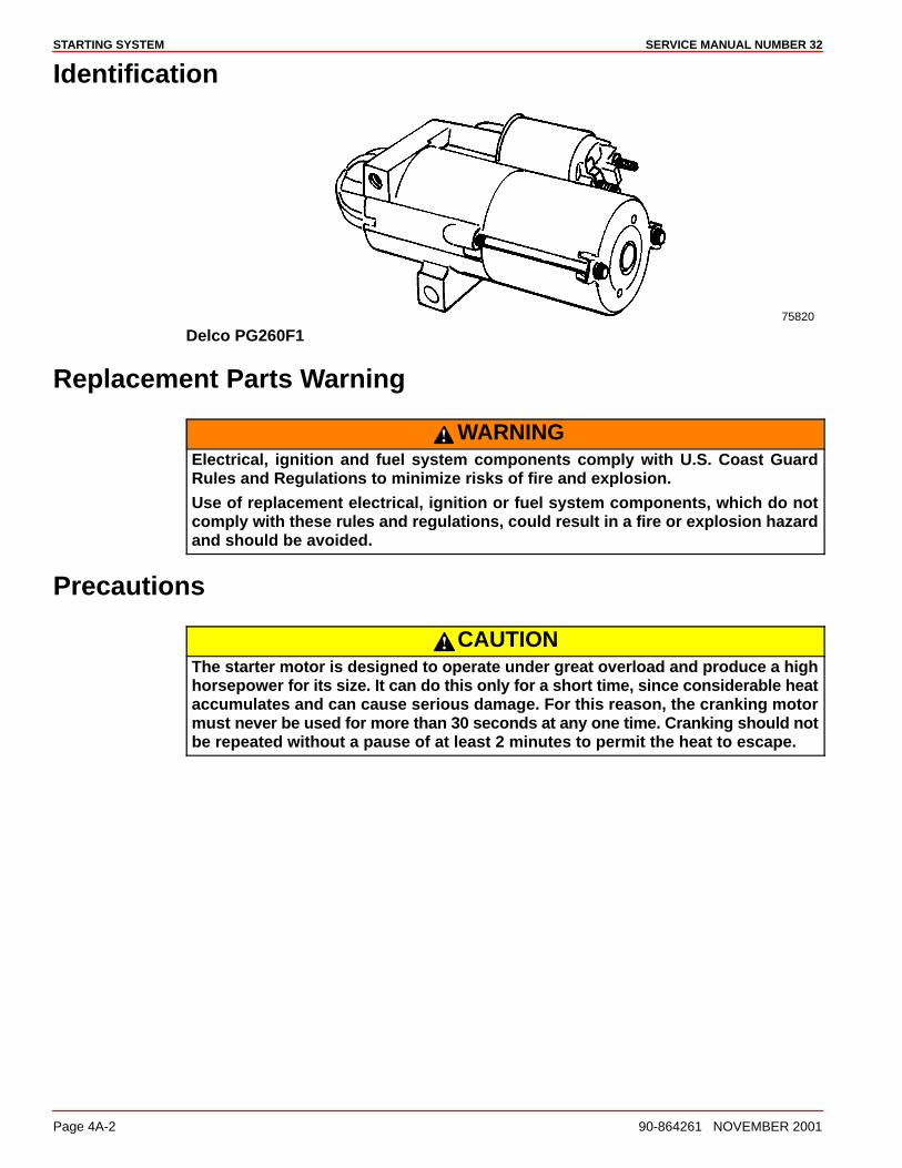
STARTING SYSTEM SERVICE MANUAL NUMBER 32
Page 4A-2 90-864261 NOVEMBER 2001
Identification
75820
Delco PG260F1
Replacement Parts Warning
WARNINGElectrical, ignition and fuel system components comply with U.S. Coast GuardRules and Regulations to minimize risks of fire and explosion.
Use of replacement electrical, ignition or fuel system components, which do notcomply with these rules and regulations, could result in a fire or explosion hazardand should be avoided.
Precautions
CAUTIONThe starter motor is designed to operate under great overload and produce a highhorsepower for its size. It can do this only for a short time, since considerable heataccumulates and can cause serious damage. For this reason, the cranking motormust never be used for more than 30 seconds at any one time. Cranking should notbe repeated without a pause of at least 2 minutes to permit the heat to escape.
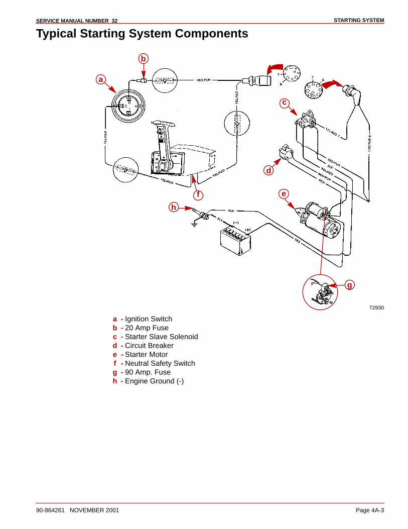
STARTING SYSTEMSERVICE MANUAL NUMBER 32
90-864261 NOVEMBER 2001 Page 4A-3
Typical Starting System Components
72930
BS
I
a
b
c
d
ef
g
h
a - Ignition Switchb - 20 Amp Fusec - Starter Slave Solenoidd - Circuit Breakere - Starter Motorf - Neutral Safety Switchg - 90 Amp. Fuseh - Engine Ground (-)
STARTING SYSTEM SERVICE MANUAL NUMBER 32
Page 4A-4 90-864261 NOVEMBER 2001
Positive Current Flow
This is a general description of the positive current flow from the battery through the systemuntil the starter motor cranks.
NOTE: Ensure that all connections are tight and have the required resistance.
• Battery to the solenoid switch (on starter) (RED battery cable).
• Solenoid switch to the circuit breaker (RED).
• Circuit breaker to the wire junction (RED/PUR).
• Wire junction to the wiring harness plug (RED/PUR) terminal 6.
• Wiring harness plug to the 20 amp fuse (RED/PUR).
• 20 amp fuse to the ignition switch terminal I (RED/PUR). At this point, the ignitionswitch is turned to START.
• Ignition switch terminal I to terminal C.
• Ignition switch terminal C to the neutral start switch (YEL/RED). NEUTRAL STARTSWITCH MUST BE AT NEUTRAL POSITION.
• Neutral start switch to the wiring harness plug terminal 7 (YEL/RED).
• Wiring harness plug to the starter solenoid (small terminal) (YEL/RED). Also, ensurethat the black (small terminal) wire is grounded.
• Starter solenoid is now closed, completing the circuit between the large terminal(RED/PUR) and the other large terminal (YEL/RED), causing the starter motor tocrank.
Battery
Battery Cable RecommendationsIMPORTANT: The terminals must be soldered to the cable ends to ensure goodelectrical contact. Use electrical grade (resin flux) solder only. Do not use acid fluxsolder as it may cause corrosion and failure.
Cable Length Cable Gauge
1.1 m (Up to 3-1/2 ft) 25 mm2 (4)
1.1 - 1.8 m (3-1/2 - 6 ft) 35 mm2 (2)
1.8 - 2.3 m (6 ft - 7-1/2 ft) 50 mm2 (1)
2.3 - 2.9 m (7-1/2 - 9-1/2 ft) 50 mm2 (0)
2.9 - 3.7 m (9-1/2 - 12 ft) 70 mm2 (00)
3.7 - 4.6 m (12 - 15 ft) 95 mm2 (000)
4.6 - 5.8 m (15 - 19 ft) 120 mm2 (0000)
Both positive (+) and negative (–) cables
STARTING SYSTEMSERVICE MANUAL NUMBER 32
90-864261 NOVEMBER 2001 Page 4A-5
Delco PG260F1 Starter
Specifications
Starter Specifications
PG260F1 Starter Motor
Mercury MerCruiser Part Number 50-863007A1
Delco No Load TestDelcoIdentification
Number
EngineRotation Volts Minimum
AmpMaximum
AmpMinimum
rpmMaximum
rpm
9000884 LH 12.0 35 85 2550 4150
Torque Specifications
Description Nm lb-in. lb-ft
Starter Mounting Bolts 41 30
Battery Terminal 9.5 84
Switch Terminal 2.3 20
Resistor Terminal 2.3 20
External Thru-bolt 4.6 41
All Other Fasteners Tighten Securely
Lubricants / Sealants / Adhesives
Description Where Used Part Number
Liquid Neoprene Terminals on the starter solenoid 92-25711--3
Description
The Permanent Magnet Gear Reduction starter motors feature small permanent magnetsmounted inside the field frame (NOTE: The actual configuration of these magnets differsbetween the PG200, PG250 and PG260; the field frames with permanent magnets are notinterchangeable. Otherwise, the units are similar.) These magnets take the place ofcurrent-carrying field coils mounted on iron pole pieces. Internal gear reduction,approximately 4:1 ratio, through planetary gears results in armature speeds in the 7000 rpmrange. The armature and drive shaft are mounted on roller or ball bearings in place ofbushings. The solenoid switch, plunger, return spring, and shift lever are permanentlymounted in the drive housing.
STARTING SYSTEM SERVICE MANUAL NUMBER 32
Page 4A-6 90-864261 NOVEMBER 2001
TestingOther than water damage, low voltage causes most starter motor failures. Low voltagecauses excessive heat to build up in the starter motor. It can also cause starter motorsolenoid contact problems.
IMPORTANT: Perform these tests with a digital voltmeter before removing the starterfrom the engine.
1. Set the digital voltmeter to zero before testing.
2. Ensure that the battery is fully charged.
3. Remove the coil wire from the distributor cap and ground it to prevent the engine fromstarting.
4. Connect the voltmeter positive (+) lead directly to the large, threaded terminal.
5. Connect the voltmeter negative (–) lead directly to an unpainted metal surface on thestarter housing.
6. Crank the engine over with the key switch for 10-15 seconds while watching thevoltmeter.
• A voltmeter reading of 9.5 volts or more indicates that the battery is supplyingsufficient voltage to the starter to operate properly. If the starter does not functionproperly, the starter or the engine are malfunctioning. Remove the spark plugs andtry turning the engine over by hand to rule out an engine problem.
• A voltmeter reading below 9.5 volts indicates a voltage loss between the startermotor and the battery. Example: Voltage measured at the battery posts indicates12.5 volts. Voltage measured at the starter indicates 9 volts. There is a 3.5 volt dropbetween the battery posts and the starter. Corroded battery cables, loose or dirtyconnections, loose battery cable terminal crimps, under size battery cable gauge forlength used in boat, painted surfaces or battery switches could be the cause of thisvoltage drop.
IMPORTANT: The maximum voltage drop allowed is 0.5 volts.
LOW VOLTAGE TEST
1. Test the battery positive (+) cable first. Connect voltmeter positive (+) lead directly to thebattery positive (+) post, not the battery cable ring terminal. Connect voltmeter negative(–) lead directly to the large, threaded starter motor terminal that the battery positive (+)cable is connected to.
NOTE: Remove one voltmeter lead before starter motor is turned off or voltmeter damagemay occur. The starter may produce a voltage spike that can damage a voltmeter.
2. Crank the engine over while watching the voltmeter. The maximum allowed drop is 0.25volts.
STARTING SYSTEMSERVICE MANUAL NUMBER 32
90-864261 NOVEMBER 2001 Page 4A-7
3. To find the point where the resistance is highest, leave the voltmeter positive (+) leadon the battery post and move the voltmeter negative (–) lead to the battery positive (+)cable ring terminal, that is on the threaded starter terminal.
4. Move voltmeter negative (–) lead to the battery cable itself that is inside the crimpedbattery cable ring terminal.
5. Test each battery cable connection in this manner all the way back to the battery positive(+) post. If a battery switch is used, check between the battery cable ring terminal andthe switch’s terminal.
6. Check for voltage drop on battery negative (–) cable. Connect voltmeter negative (–)lead directly to the battery negative (–) post, not the battery cable ring terminal. Connectvoltmeter positive (+) lead to an unpainted surface of the starter housing.
NOTE: Remove one voltmeter lead before starter motor is turned off or voltmeter damagemay occur. The starter may produce a voltage spike that can damage a voltmeter.
7. Crank engine over while looking at the voltmeter.
IMPORTANT: The maximum allowed drop is 0.25 volts.
8. To find the point where the resistance is highest, leave voltmeter negative (–) lead onbattery negative (–) post and move voltmeter positive (+) lead to the ground stud wherethe battery negative (–) cable is connected.
9. Move the voltmeter negative (+) lead to the battery negative (–) cable ring terminal thatis on the ground stud.
10. Move voltmeter positive (+) lead to the battery cable itself that is inside the crimpedbattery cable ring terminal.
11. Test each battery cable connection in this manner back to the battery post.
12. After testing to ensure that the starter motor is getting at least 9.5 volts, test the startermotor solenoid to see if it is getting at least 9.5 volts from the slave solenoid duringcranking. Low voltage at the starter solenoid can cause intermittent operation of thesolenoid contacts and shorten the life of the solenoid.
13. Connect the voltmeter positive (+) lead to the terminal on the starter solenoid that hasthe YEL/RED wire from the slave solenoid connected to it.
14. Connect the voltmeter negative (–) lead to unpainted surface of the starter housing.
15. Crank engine over and watch the voltmeter. If the starter solenoid is not getting 9.5 volts,the YEL/RED wire or the slave solenoid could be the cause of the low voltage.
WATER OR CORROSION INSPECTION
1. Remove the 2 short screws from the end cap and look at the threads.
• If they are clean and gold in color, the starter motor did not have water inside of it.
• If they are dirty and black or gray in color, the starter motor may have had water onthe inside of it and it should be replaced.
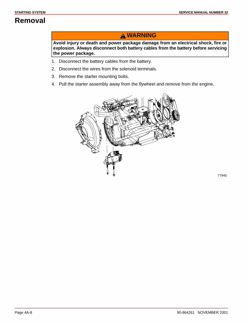
STARTING SYSTEM SERVICE MANUAL NUMBER 32
Page 4A-8 90-864261 NOVEMBER 2001
Removal
WARNINGAvoid injury or death and power package damage from an electrical shock, fire orexplosion. Always disconnect both battery cables from the battery before servicingthe power package.
1. Disconnect the battery cables from the battery.
2. Disconnect the wires from the solenoid terminals.
3. Remove the starter mounting bolts.
4. Pull the starter assembly away from the flywheel and remove from the engine.
77945
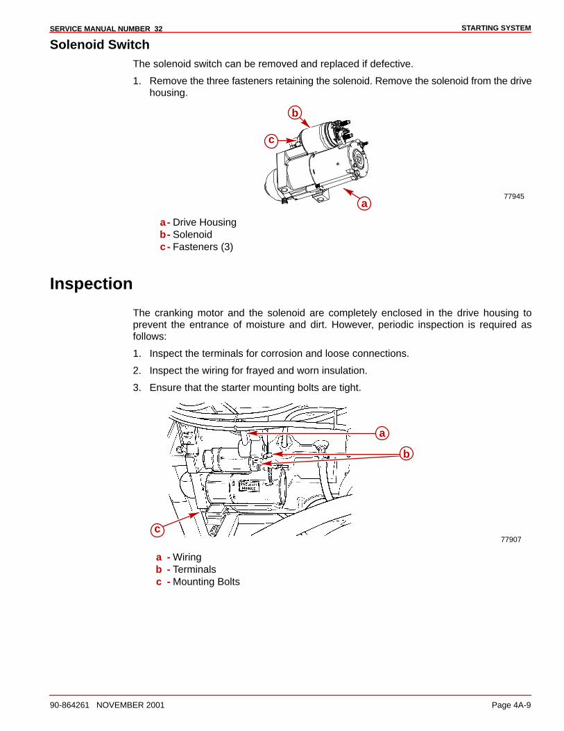
STARTING SYSTEMSERVICE MANUAL NUMBER 32
90-864261 NOVEMBER 2001 Page 4A-9
Solenoid SwitchThe solenoid switch can be removed and replaced if defective.
1. Remove the three fasteners retaining the solenoid. Remove the solenoid from the drivehousing.
77945a
c
b
a- Drive Housingb- Solenoidc- Fasteners (3)
Inspection
The cranking motor and the solenoid are completely enclosed in the drive housing toprevent the entrance of moisture and dirt. However, periodic inspection is required asfollows:
1. Inspect the terminals for corrosion and loose connections.
2. Inspect the wiring for frayed and worn insulation.
3. Ensure that the starter mounting bolts are tight.
77907
a
c
b
a - Wiringb - Terminalsc - Mounting Bolts
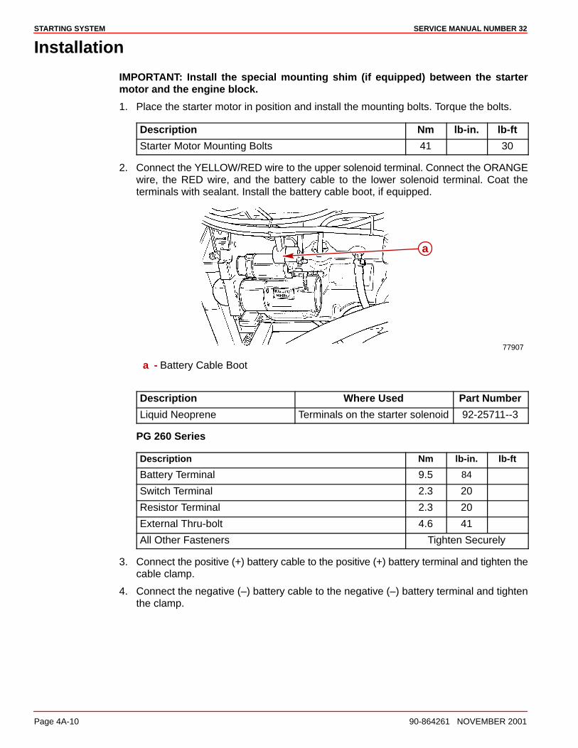
STARTING SYSTEM SERVICE MANUAL NUMBER 32
Page 4A-10 90-864261 NOVEMBER 2001
Installation
IMPORTANT: Install the special mounting shim (if equipped) between the startermotor and the engine block.
1. Place the starter motor in position and install the mounting bolts. Torque the bolts.
Description Nm lb-in. lb-ft
Starter Motor Mounting Bolts 41 30
2. Connect the YELLOW/RED wire to the upper solenoid terminal. Connect the ORANGEwire, the RED wire, and the battery cable to the lower solenoid terminal. Coat theterminals with sealant. Install the battery cable boot, if equipped.
77907
a
a - Battery Cable Boot
Description Where Used Part Number
Liquid Neoprene Terminals on the starter solenoid 92-25711--3
PG 260 Series
Description Nm lb-in. lb-ft
Battery Terminal 9.5 84
Switch Terminal 2.3 20
Resistor Terminal 2.3 20
External Thru-bolt 4.6 41
All Other Fasteners Tighten Securely
3. Connect the positive (+) battery cable to the positive (+) battery terminal and tighten thecable clamp.
4. Connect the negative (–) battery cable to the negative (–) battery terminal and tightenthe clamp.
4B
IGNITION SYSTEMSERVICE MANUAL NUMBER 32
90-864261 NOVEMBER 2001 Page 4B-1
ELECTRICAL SYSTEMSection 4B - Ignition System
Table of Contents
Specifications 4B-2. . . . . . . . . . . . . . . . . . . . . . . . . Spark Plugs 4B-2. . . . . . . . . . . . . . . . . . . . . . . . Distributor 4B-2. . . . . . . . . . . . . . . . . . . . . . . . . Coil 4B-2. . . . . . . . . . . . . . . . . . . . . . . . . . . . . . . Firing Order 4B-2. . . . . . . . . . . . . . . . . . . . . . . .
Torque Specifications 4B-2. . . . . . . . . . . . . . . . . . Lubricants / Sealants / Adhesives 4B-3. . . . . . . Spark Plugs 4B-3. . . . . . . . . . . . . . . . . . . . . . . . . .
Removal 4B-3. . . . . . . . . . . . . . . . . . . . . . . . . . Inspection 4B-3. . . . . . . . . . . . . . . . . . . . . . . . . Replacing 4B-4. . . . . . . . . . . . . . . . . . . . . . . . .
Spark Plug Wires 4B-5. . . . . . . . . . . . . . . . . . . . . . Inspection 4B-5. . . . . . . . . . . . . . . . . . . . . . . . . Replacing 4B-5. . . . . . . . . . . . . . . . . . . . . . . . .
Ignition Coil 4B-7. . . . . . . . . . . . . . . . . . . . . . . . . . . Removal 4B-7. . . . . . . . . . . . . . . . . . . . . . . . . . Installation 4B-8. . . . . . . . . . . . . . . . . . . . . . . . .
Distributor 4B-9. . . . . . . . . . . . . . . . . . . . . . . . . . . . Removal 4B-9. . . . . . . . . . . . . . . . . . . . . . . . . . Disassembly 4B-10. . . . . . . . . . . . . . . . . . . . . . Cleaning and Inspection 4B-12. . . . . . . . . . . . Reassembly 4B-12. . . . . . . . . . . . . . . . . . . . . . Installation 4B-13. . . . . . . . . . . . . . . . . . . . . . . .
IGNITION SYSTEM SERVICE MANUAL NUMBER 32
Page 4B-2 90-864261 NOVEMBER 2001
Specifications
Spark Plugs
Description Specification
Spark PlugAC Platinum
(AC 41-932)0.060 in. Gap
Distributor
Description Part Number
Distributor Not Available at Time of Printing
Coil
Description Specification
Coil Part Number 392-863704
Primary Resistance 0.60 - 0.80 Ohms
Secondary Resistance 9,400-11,700 Ohms
Firing Order
Description Specification
Firing Order 1-6-5-4-3-2
Torque Specifications
Description Nm lb-in. lb-ft
Spark PlugsInitial Installation (NEWCylinder Head)
30 22Spark Plugs
All Subsequent Installations 15 11
Distributor Hold Down Clamp 25 18
Lubricants / Sealants / Adhesives
Description Where Used Part Number
Silicone Dielectric Compound Coil High Tension Lead Tower 92-823506-1
Special Tools
Description Part Number
Multi-Meter / DVA Tester (DMM) 91-99750A1
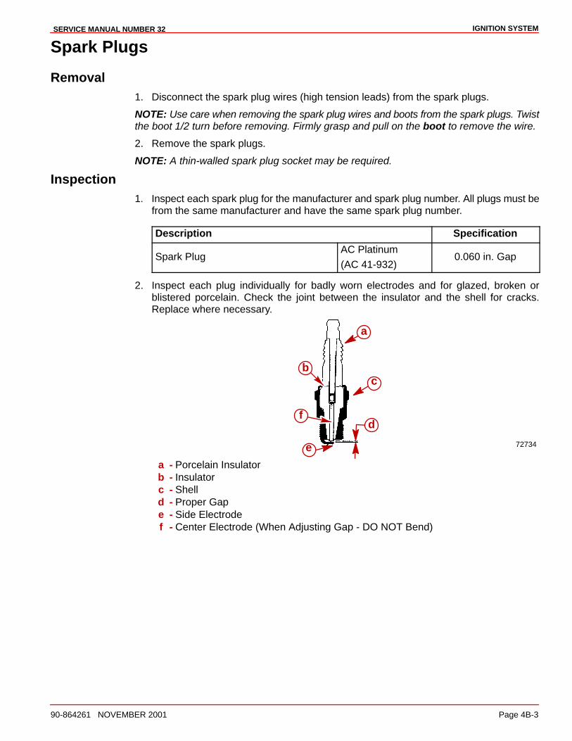
IGNITION SYSTEMSERVICE MANUAL NUMBER 32
90-864261 NOVEMBER 2001 Page 4B-3
Spark Plugs
Removal1. Disconnect the spark plug wires (high tension leads) from the spark plugs.
NOTE: Use care when removing the spark plug wires and boots from the spark plugs. Twistthe boot 1/2 turn before removing. Firmly grasp and pull on the boot to remove the wire.
2. Remove the spark plugs.
NOTE: A thin-walled spark plug socket may be required.
Inspection1. Inspect each spark plug for the manufacturer and spark plug number. All plugs must be
from the same manufacturer and have the same spark plug number.
Description Specification
Spark PlugAC Platinum
(AC 41-932)0.060 in. Gap
2. Inspect each plug individually for badly worn electrodes and for glazed, broken orblistered porcelain. Check the joint between the insulator and the shell for cracks.Replace where necessary.
72734
a
c
d
e
b
f
a - Porcelain Insulatorb - Insulatorc - Shelld - Proper Gape - Side Electrodef - Center Electrode (When Adjusting Gap - DO NOT Bend)
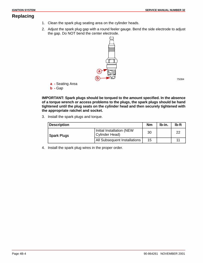
IGNITION SYSTEM SERVICE MANUAL NUMBER 32
Page 4B-4 90-864261 NOVEMBER 2001
Replacing1. Clean the spark plug seating area on the cylinder heads.
2. Adjust the spark plug gap with a round feeler gauge. Bend the side electrode to adjustthe gap. Do NOT bend the center electrode.
75084
a
ba - Seating Areab - Gap
IMPORTANT: Spark plugs should be torqued to the amount specified. In the absenceof a torque wrench or access problems to the plugs, the spark plugs should be handtightened until the plug seats on the cylinder head and then securely tightened withthe appropriate ratchet and socket.
3. Install the spark plugs and torque.
Description Nm lb-in. lb-ft
Spark PlugsInitial Installation (NEWCylinder Head)
30 22Spark Plugs
All Subsequent Installations 15 11
4. Install the spark plug wires in the proper order.
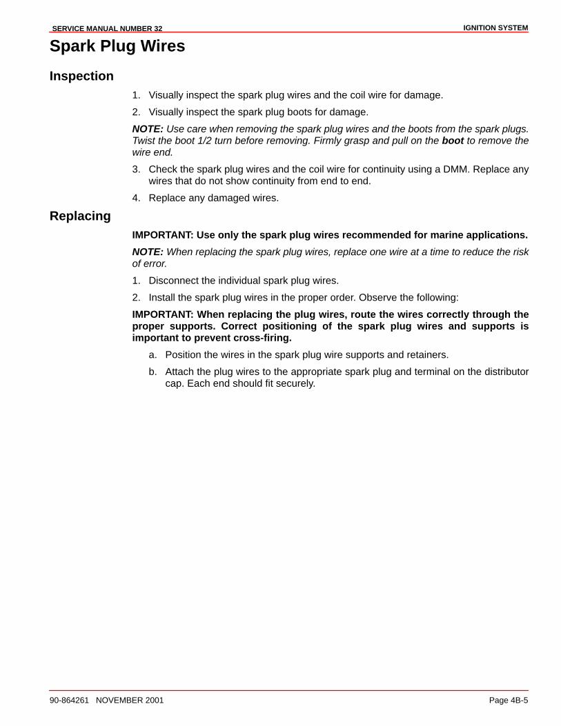
IGNITION SYSTEMSERVICE MANUAL NUMBER 32
90-864261 NOVEMBER 2001 Page 4B-5
Spark Plug Wires
Inspection1. Visually inspect the spark plug wires and the coil wire for damage.
2. Visually inspect the spark plug boots for damage.
NOTE: Use care when removing the spark plug wires and the boots from the spark plugs.Twist the boot 1/2 turn before removing. Firmly grasp and pull on the boot to remove thewire end.
3. Check the spark plug wires and the coil wire for continuity using a DMM. Replace anywires that do not show continuity from end to end.
4. Replace any damaged wires.
ReplacingIMPORTANT: Use only the spark plug wires recommended for marine applications.
NOTE: When replacing the spark plug wires, replace one wire at a time to reduce the riskof error.
1. Disconnect the individual spark plug wires.
2. Install the spark plug wires in the proper order. Observe the following:
IMPORTANT: When replacing the plug wires, route the wires correctly through theproper supports. Correct positioning of the spark plug wires and supports isimportant to prevent cross-firing.
a. Position the wires in the spark plug wire supports and retainers.
b. Attach the plug wires to the appropriate spark plug and terminal on the distributorcap. Each end should fit securely.
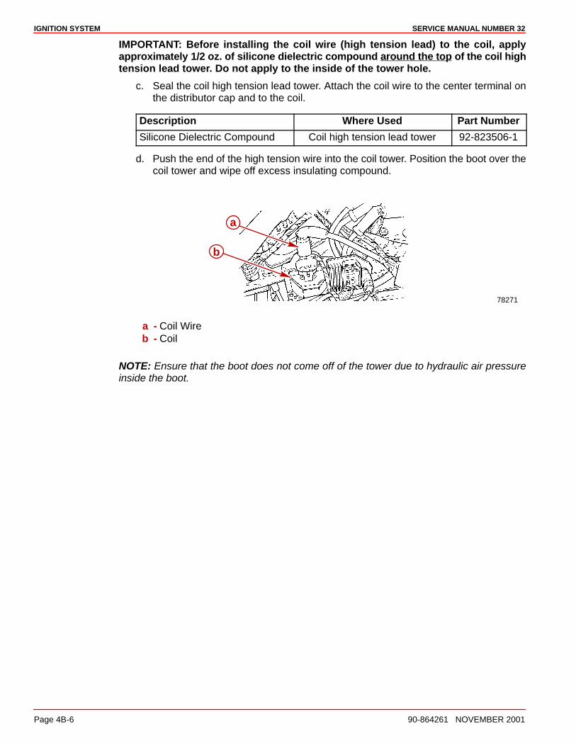
IGNITION SYSTEM SERVICE MANUAL NUMBER 32
Page 4B-6 90-864261 NOVEMBER 2001
IMPORTANT: Before installing the coil wire (high tension lead) to the coil, applyapproximately 1/2 oz. of silicone dielectric compound around the top of the coil hightension lead tower. Do not apply to the inside of the tower hole.
c. Seal the coil high tension lead tower. Attach the coil wire to the center terminal onthe distributor cap and to the coil.
Description Where Used Part Number
Silicone Dielectric Compound Coil high tension lead tower 92-823506-1
d. Push the end of the high tension wire into the coil tower. Position the boot over thecoil tower and wipe off excess insulating compound.
78271
a
b
a - Coil Wireb - Coil
NOTE: Ensure that the boot does not come off of the tower due to hydraulic air pressureinside the boot.
IGNITION SYSTEMSERVICE MANUAL NUMBER 32
90-864261 NOVEMBER 2001 Page 4B-7
Ignition Coil
Removal1. Disconnect the wire harness connector at the coil.
2. Disconnect the ignition module wire harness connector.
3. Remove the high tension coil lead.
78271
c
b
a
a - Coil Wire Harness Connectionb - Ignition Module Wire Connectionc - High Tension Coil Lead Connection
4. Remove the coil bracket fasteners and remove the coil bracket assembly from theengine.
5. Remove the coil from the coil bracket.
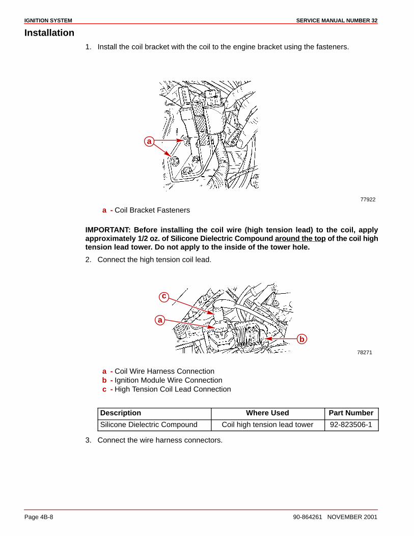
IGNITION SYSTEM SERVICE MANUAL NUMBER 32
Page 4B-8 90-864261 NOVEMBER 2001
Installation1. Install the coil bracket with the coil to the engine bracket using the fasteners.
77922
a
a - Coil Bracket Fasteners
IMPORTANT: Before installing the coil wire (high tension lead) to the coil, applyapproximately 1/2 oz. of Silicone Dielectric Compound around the top of the coil hightension lead tower. Do not apply to the inside of the tower hole.
2. Connect the high tension coil lead.
78271
c
b
a
a - Coil Wire Harness Connectionb - Ignition Module Wire Connectionc - High Tension Coil Lead Connection
Description Where Used Part Number
Silicone Dielectric Compound Coil high tension lead tower 92-823506-1
3. Connect the wire harness connectors.
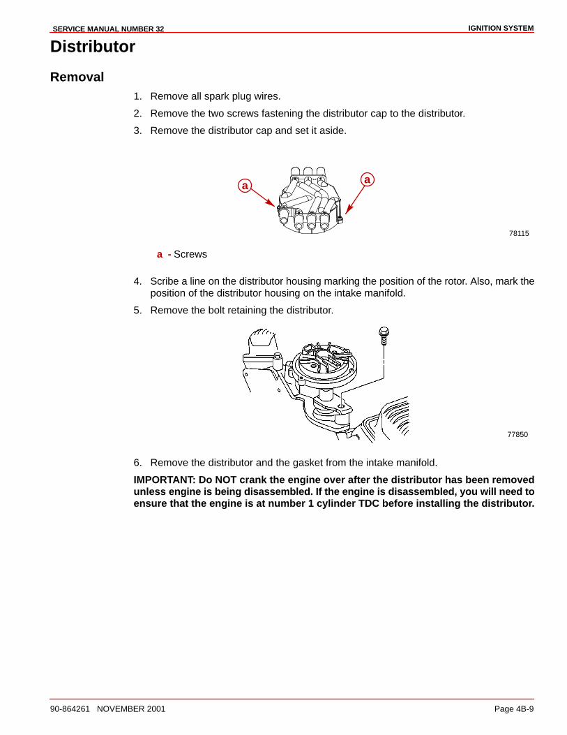
IGNITION SYSTEMSERVICE MANUAL NUMBER 32
90-864261 NOVEMBER 2001 Page 4B-9
Distributor
Removal1. Remove all spark plug wires.
2. Remove the two screws fastening the distributor cap to the distributor.
3. Remove the distributor cap and set it aside.
78115
a a
a - Screws
4. Scribe a line on the distributor housing marking the position of the rotor. Also, mark theposition of the distributor housing on the intake manifold.
5. Remove the bolt retaining the distributor.
77850
6. Remove the distributor and the gasket from the intake manifold.
IMPORTANT: Do NOT crank the engine over after the distributor has been removedunless engine is being disassembled. If the engine is disassembled, you will need toensure that the engine is at number 1 cylinder TDC before installing the distributor.
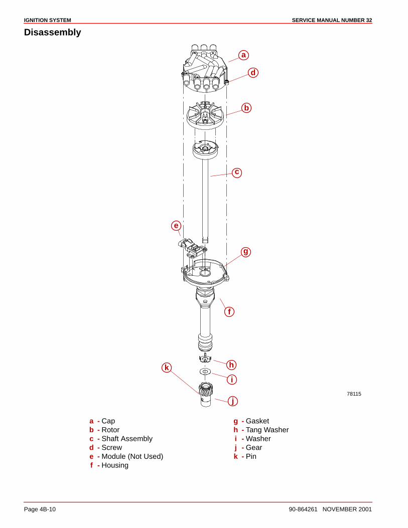
IGNITION SYSTEM SERVICE MANUAL NUMBER 32
Page 4B-10 90-864261 NOVEMBER 2001
Disassembly
i
k
j
i
h
g
f
e
d
c
b
a
78115
a - Capb - Rotorc - Shaft Assemblyd - Screwe - Module (Not Used)f - Housing
g - Gasketh - Tang Washeri - Washerj - Geark - Pin
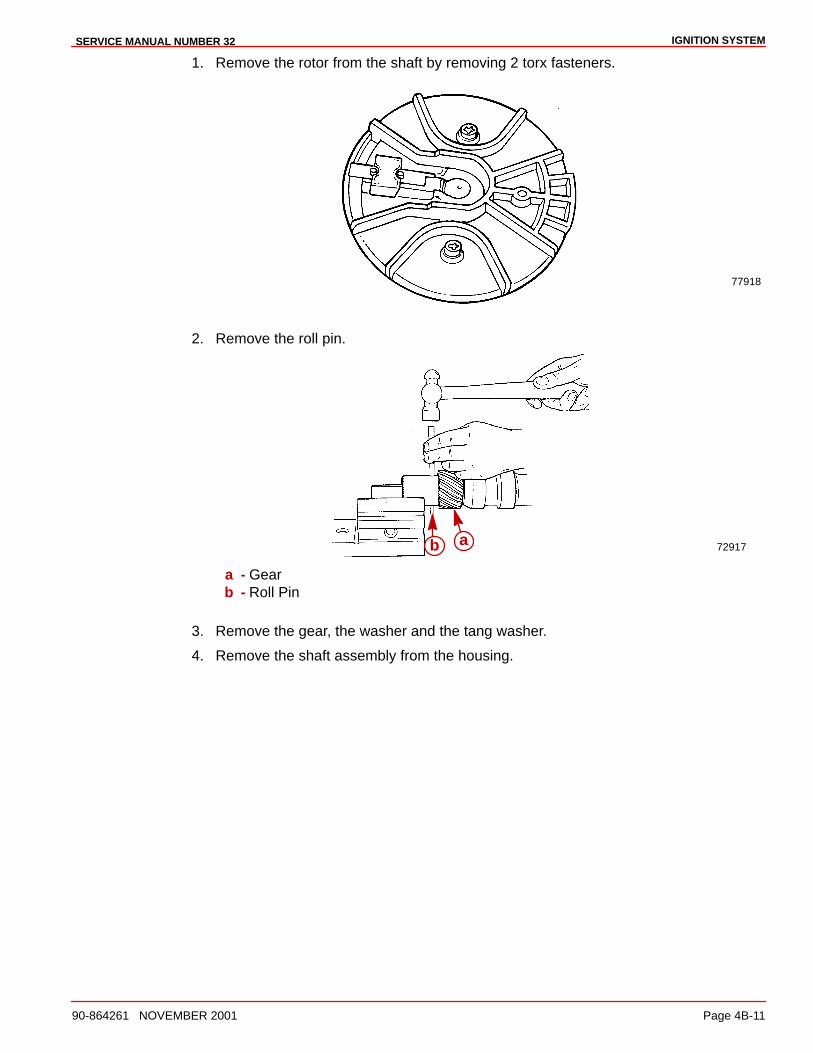
IGNITION SYSTEMSERVICE MANUAL NUMBER 32
90-864261 NOVEMBER 2001 Page 4B-11
1. Remove the rotor from the shaft by removing 2 torx fasteners.
77918
2. Remove the roll pin.
72917b a
a - Gearb - Roll Pin
3. Remove the gear, the washer and the tang washer.
4. Remove the shaft assembly from the housing.
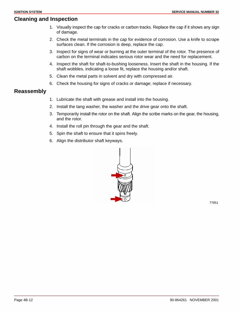
IGNITION SYSTEM SERVICE MANUAL NUMBER 32
Page 4B-12 90-864261 NOVEMBER 2001
Cleaning and Inspection1. Visually inspect the cap for cracks or carbon tracks. Replace the cap if it shows any sign
of damage.
2. Check the metal terminals in the cap for evidence of corrosion. Use a knife to scrapesurfaces clean. If the corrosion is deep, replace the cap.
3. Inspect for signs of wear or burning at the outer terminal of the rotor. The presence ofcarbon on the terminal indicates serious rotor wear and the need for replacement.
4. Inspect the shaft for shaft-to-bushing looseness. Insert the shaft in the housing. If theshaft wobbles, indicating a loose fit, replace the housing and/or shaft.
5. Clean the metal parts in solvent and dry with compressed air.
6. Check the housing for signs of cracks or damage; replace if necessary.
Reassembly1. Lubricate the shaft with grease and install into the housing.
2. Install the tang washer, the washer and the drive gear onto the shaft.
3. Temporarily install the rotor on the shaft. Align the scribe marks on the gear, the housing,and the rotor.
4. Install the roll pin through the gear and the shaft.
5. Spin the shaft to ensure that it spins freely.
6. Align the distributor shaft keyways.
77851
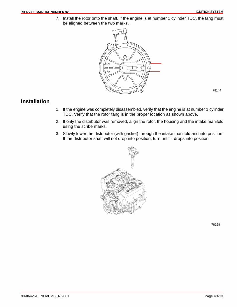
IGNITION SYSTEMSERVICE MANUAL NUMBER 32
90-864261 NOVEMBER 2001 Page 4B-13
7. Install the rotor onto the shaft. If the engine is at number 1 cylinder TDC, the tang mustbe aligned between the two marks.
78144
Installation1. If the engine was completely disassembled, verify that the engine is at number 1 cylinder
TDC. Verify that the rotor tang is in the proper location as shown above.
2. If only the distributor was removed, align the rotor, the housing and the intake manifoldusing the scribe marks.
3. Slowly lower the distributor (with gasket) through the intake manifold and into position.If the distributor shaft will not drop into position, turn until it drops into position.
78268

IGNITION SYSTEM SERVICE MANUAL NUMBER 32
Page 4B-14 90-864261 NOVEMBER 2001
4. Install the hold-down clamp over the distributor and bolt it securely to the engine surface.Torque the bolt.
Description Nm lb-in. lb-ft
Distributor Hold Down Clamp 40 30
5. Install the distributor cap and secure in place with two torx fasteners.
6. Connect the spark plug wires.
78254
a
b
a - Plug Not Usedb - Spark Plug Wires
4C
CHARGING SYSTEMSERVICE MANUAL NUMBER 32
90-864261 NOVEMBER 2001 Page 4C-1
ELECTRICAL SYSTEMSection 4C - Charging System
Table of Contents
Delco Alternator 4C-2. . . . . . . . . . . . . . . . . . . . . Identification 4C-2. . . . . . . . . . . . . . . . . . . . . Replacement Parts Warning 4C-2. . . . . . . Specifications 4C-3. . . . . . . . . . . . . . . . . . . . Torque Specifications 4C-3. . . . . . . . . . . . . Special Tools 4C-3. . . . . . . . . . . . . . . . . . . . .
Precautions 4C-4. . . . . . . . . . . . . . . . . . . . . . . . EFI Electrical System Precautions 4C-4. .
Charging System Components 4C-5. . . . . . . . Periodic Maintenance 4C-5. . . . . . . . . . . . . . . .
Troubleshooting Tests (Alternator on Engine) 4C-5. . . . . . . . . . . . . . .
Charging System 4C-6. . . . . . . . . . . . . . . . . Resistance 4C-7. . . . . . . . . . . . . . . . . . . . . . Circuitry 4C-9. . . . . . . . . . . . . . . . . . . . . . . . .
Removal 4C-11. . . . . . . . . . . . . . . . . . . . . . . . . . . Alternator 4C-11. . . . . . . . . . . . . . . . . . . . . . . . Alternator Bracket 4C-11. . . . . . . . . . . . . . . .
Installation 4C-12. . . . . . . . . . . . . . . . . . . . . . . . . Alternator Bracket 4C-12. . . . . . . . . . . . . . . . Alternator 4C-12. . . . . . . . . . . . . . . . . . . . . . . . Battery Isolator Diagram 4C-14. . . . . . . . . . .
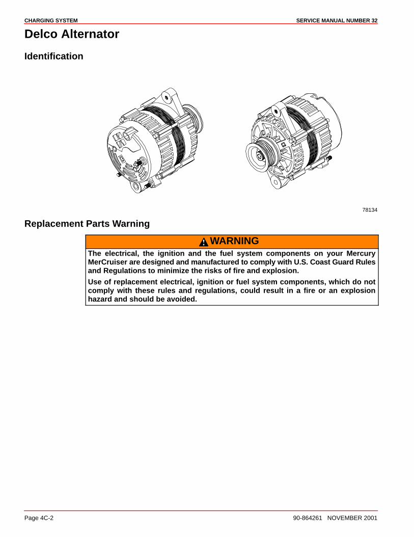
SERVICE MANUAL NUMBER 32CHARGING SYSTEM
Page 4C-2 90-864261 NOVEMBER 2001
Delco Alternator
Identification
78134
Replacement Parts Warning
WARNINGThe electrical, the ignition and the fuel system components on your MercuryMerCruiser are designed and manufactured to comply with U.S. Coast Guard Rulesand Regulations to minimize the risks of fire and explosion.
Use of replacement electrical, ignition or fuel system components, which do notcomply with these rules and regulations, could result in a fire or an explosionhazard and should be avoided.
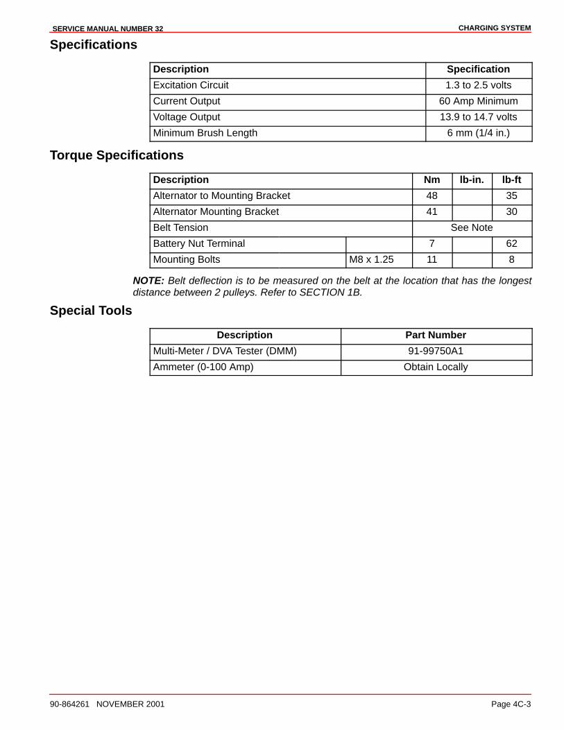
CHARGING SYSTEMSERVICE MANUAL NUMBER 32
90-864261 NOVEMBER 2001 Page 4C-3
Specifications
Description Specification
Excitation Circuit 1.3 to 2.5 volts
Current Output 60 Amp Minimum
Voltage Output 13.9 to 14.7 volts
Minimum Brush Length 6 mm (1/4 in.)
Torque Specifications
Description Nm lb-in. lb-ft
Alternator to Mounting Bracket 48 35
Alternator Mounting Bracket 41 30
Belt Tension See Note
Battery Nut Terminal 7 62
Mounting Bolts M8 x 1.25 11 8
NOTE: Belt deflection is to be measured on the belt at the location that has the longestdistance between 2 pulleys. Refer to SECTION 1B.
Special Tools
Description Part Number
Multi-Meter / DVA Tester (DMM) 91-99750A1
Ammeter (0-100 Amp) Obtain Locally
SERVICE MANUAL NUMBER 32CHARGING SYSTEM
Page 4C-4 90-864261 NOVEMBER 2001
Precautions
The following precautions MUST BE observed when working on the charging system.Failure to observe these precautions may result in serious damage to the alternator orcharging system.
1. Do NOT attempt to polarize the alternator.
2. Do NOT short across or ground any of the terminals on the alternator, except asspecifically instructed in the Troubleshooting Tests.
3. NEVER disconnect the alternator output lead or battery cables when the alternator isoperating.
4. NEVER disconnect the regulator lead from the alternator regulator terminal when thealternator is operating.
5. ALWAYS remove the negative (–) battery cable from the battery before working on thecharging system.
6. When installing the battery, BE SURE to connect the positive (+) battery cable to thepositive (+) battery terminal and the negative (–) (grounded) battery cable to thenegative (–) battery terminal.
7. If a charger or booster battery is to be used, BE SURE to connect it in parallel with theexisting battery (positive to positive; negative to negative).
EFI Electrical System Precautions
CAUTIONAvoid damage to the EFI electrical system and components. Refer to the followingprecautions when working on or around the EFI electrical harness or when addingother electrical accessories:
• DO NOT tap accessories into the engine harness.
• DO NOT puncture wires for testing (Probing).
• DO NOT reverse the battery leads.
• DO NOT splice wires into the harness.
• DO NOT attempt diagnostics without proper, approved Service Tools.
CHARGING SYSTEMSERVICE MANUAL NUMBER 32
90-864261 NOVEMBER 2001 Page 4C-5
Charging System Components
The charging system consists of the alternator, the battery, the ignition switch and the wiringthat connects these components.
Periodic Maintenance
WARNINGAvoid injury or death and power package damage from an electrical shock, fire orexplosion. Always disconnect both battery cables from the battery before servicingthe power package.
1. Inspect the entire alternator system for corroded or loose connectors.
2. Check the wiring for frayed or worn insulation.
3. Check the alternator drive belt for excessive wear, cracks, fraying and glazed surfaces.Also, check the drive belt tension and adjust; refer to SECTION 1B.
4. Check the alternator mounting bolts for adequate tightness.
5. Inspect the flame arrestor screen for debris and clean using compressed air or a cloth.The screen MUST BE clean or the alternator may overheat.
Troubleshooting Tests (Alternator on Engine)
Use the following tests in conjunction with SECTION 1C - Troubleshooting. Beforeproceeding with the tests, perform the following checks to eliminate possible problem areas.Observe the Precautions to prevent damage to the alternator system.
1. An undercharged battery can be caused by excessive current draw, from accessoriesor by operating the engine at low speeds for extended periods.
2. Check the physical condition and the battery charge. The battery MUST BE at least75 percent (1.230 specific gravity) of fully charged to obtain valid results in the followingtests. If not, charge the battery before testing the system.
3. Inspect the entire charging system wiring for defects. Ensure that all connections aresecure and clean.
4. Check the alternator drive belt for excessive wear, cracks, fraying and glazed surfaces.Replace if necessary. Also, check the drive belt tension and adjust if necessary.
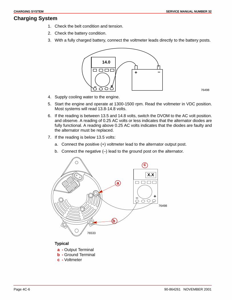
SERVICE MANUAL NUMBER 32CHARGING SYSTEM
Page 4C-6 90-864261 NOVEMBER 2001
Charging System1. Check the belt condition and tension.
2. Check the battery condition.
3. With a fully charged battery, connect the voltmeter leads directly to the battery posts.
14.0
76498+–
–+
4. Supply cooling water to the engine.
5. Start the engine and operate at 1300-1500 rpm. Read the voltmeter in VDC position.Most systems will read 13.8-14.8 volts.
6. If the reading is between 13.5 and 14.8 volts, switch the DVOM to the AC volt position.and observe. A reading of 0.25 AC volts or less indicates that the alternator diodes arefully functional. A reading above 0.25 AC volts indicates that the diodes are faulty andthe alternator must be replaced.
7. If the reading is below 13.5 volts:
a. Connect the positive (+) voltmeter lead to the alternator output post.
b. Connect the negative (–) lead to the ground post on the alternator.
76498
c
76533
a
b
X.X
+–
Typicala - Output Terminalb - Ground Terminalc - Voltmeter
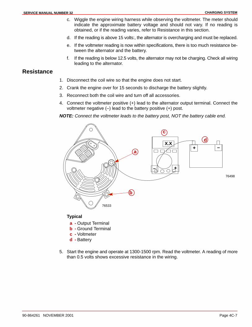
CHARGING SYSTEMSERVICE MANUAL NUMBER 32
90-864261 NOVEMBER 2001 Page 4C-7
c. Wiggle the engine wiring harness while observing the voltmeter. The meter shouldindicate the approximate battery voltage and should not vary. If no reading isobtained, or if the reading varies, refer to Resistance in this section.
d. If the reading is above 15 volts:, the alternator is overcharging and must be replaced.
e. If the voltmeter reading is now within specifications, there is too much resistance be-tween the alternator and the battery.
f. If the reading is below 12.5 volts, the alternator may not be charging. Check all wiringleading to the alternator.
Resistance1. Disconnect the coil wire so that the engine does not start.
2. Crank the engine over for 15 seconds to discharge the battery slightly.
3. Reconnect both the coil wire and turn off all accessories.
4. Connect the voltmeter positive (+) lead to the alternator output terminal. Connect thevoltmeter negative (–) lead to the battery positive (+) post.
NOTE: Connect the voltmeter leads to the battery post, NOT the battery cable end.
76498
c
76533
a
b
+–
–+
dX.X
Typicala - Output Terminalb - Ground Terminalc - Voltmeterd - Battery
5. Start the engine and operate at 1300-1500 rpm. Read the voltmeter. A reading of morethan 0.5 volts shows excessive resistance in the wiring.
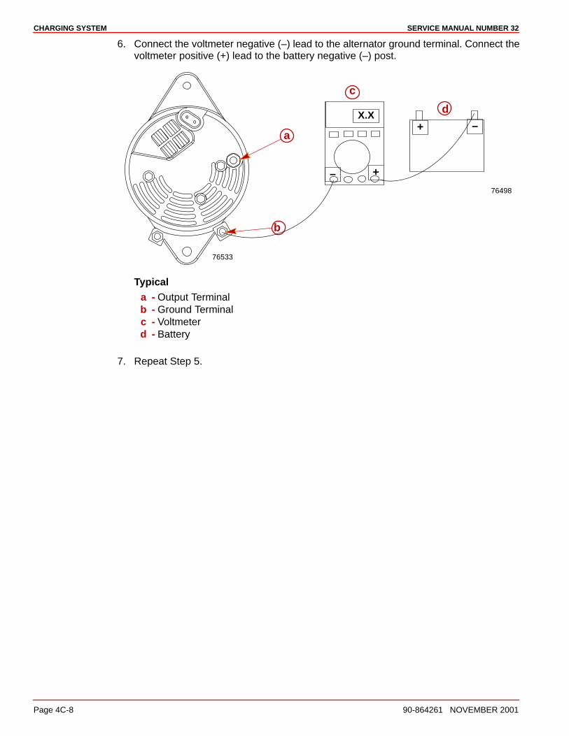
SERVICE MANUAL NUMBER 32CHARGING SYSTEM
Page 4C-8 90-864261 NOVEMBER 2001
6. Connect the voltmeter negative (–) lead to the alternator ground terminal. Connect thevoltmeter positive (+) lead to the battery negative (–) post.
76498
c
76533
a
b
+–
–+
dX.X
Typicala - Output Terminalb - Ground Terminalc - Voltmeterd - Battery
7. Repeat Step 5.
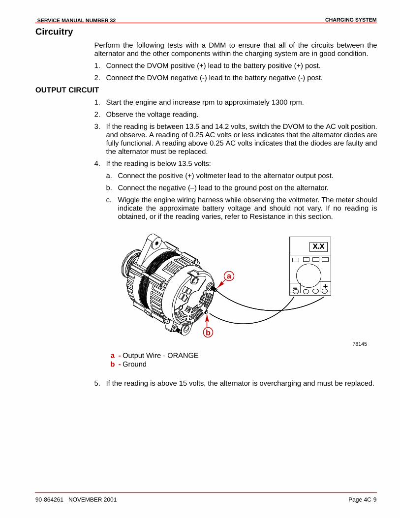
CHARGING SYSTEMSERVICE MANUAL NUMBER 32
90-864261 NOVEMBER 2001 Page 4C-9
CircuitryPerform the following tests with a DMM to ensure that all of the circuits between thealternator and the other components within the charging system are in good condition.
1. Connect the DVOM positive (+) lead to the battery positive (+) post.
2. Connect the DVOM negative (-) lead to the battery negative (-) post.
OUTPUT CIRCUIT
1. Start the engine and increase rpm to approximately 1300 rpm.
2. Observe the voltage reading.
3. If the reading is between 13.5 and 14.2 volts, switch the DVOM to the AC volt position.and observe. A reading of 0.25 AC volts or less indicates that the alternator diodes arefully functional. A reading above 0.25 AC volts indicates that the diodes are faulty andthe alternator must be replaced.
4. If the reading is below 13.5 volts:
a. Connect the positive (+) voltmeter lead to the alternator output post.
b. Connect the negative (–) lead to the ground post on the alternator.
c. Wiggle the engine wiring harness while observing the voltmeter. The meter shouldindicate the approximate battery voltage and should not vary. If no reading isobtained, or if the reading varies, refer to Resistance in this section.
+–
X.X
a
b78145
+–
X.X
a
b
a - Output Wire - ORANGEb - Ground
5. If the reading is above 15 volts, the alternator is overcharging and must be replaced.

SERVICE MANUAL NUMBER 32CHARGING SYSTEM
Page 4C-10 90-864261 NOVEMBER 2001
EXCITATION CIRCUIT
1. Connect the positive (+) voltmeter lead to the tie strap terminal on the alternator and thenegative (–) lead to a ground terminal on the alternator.
2. Turn the ignition switch to the ON position and note the voltmeter reading. The readingshould be 1.3 to 2.5 volts.
3. If no reading is obtained, an open exists in the alternator excitation lead or in theexcitation circuit of the regulator. Unplug the PURPLE lead from the regulator. Connectthe positive voltmeter lead to the PURPLE lead and the negative voltmeter leads to theground. If the voltmeter now indicates the approximate battery voltage, the voltageregulator is defective and must be replaced. If no voltage is indicated, check theexcitation circuit for loose or dirty connections or damaged wiring.
SENSING CIRCUIT
1. Unplug the RED and RED/PUR connector from the alternator.
2. Connect the positive (+) voltmeter lead to the RED/PUR pin and the negative (–)voltmeter lead to the ground terminal.
3. The voltmeter should indicate the battery voltage. If battery voltage is not present, checkthe RED/PUR wire for loose or dirty connection or damaged wiring.
78146
X.Xa
c
b
+–
a - Connector Locationb - RED and RED/PUR Connectorc - Ground
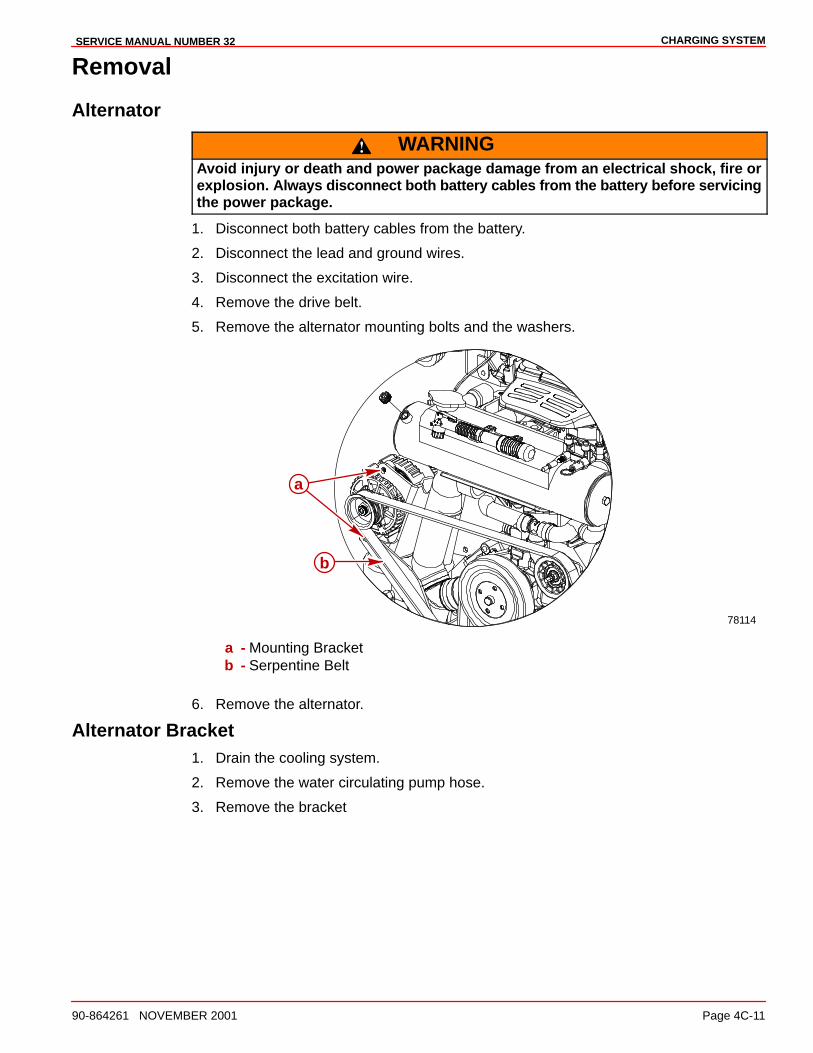
CHARGING SYSTEMSERVICE MANUAL NUMBER 32
90-864261 NOVEMBER 2001 Page 4C-11
Removal
Alternator
WARNINGAvoid injury or death and power package damage from an electrical shock, fire orexplosion. Always disconnect both battery cables from the battery before servicingthe power package.
1. Disconnect both battery cables from the battery.
2. Disconnect the lead and ground wires.
3. Disconnect the excitation wire.
4. Remove the drive belt.
5. Remove the alternator mounting bolts and the washers.
78114
a
b
a - Mounting Bracketb - Serpentine Belt
6. Remove the alternator.
Alternator Bracket1. Drain the cooling system.
2. Remove the water circulating pump hose.
3. Remove the bracket
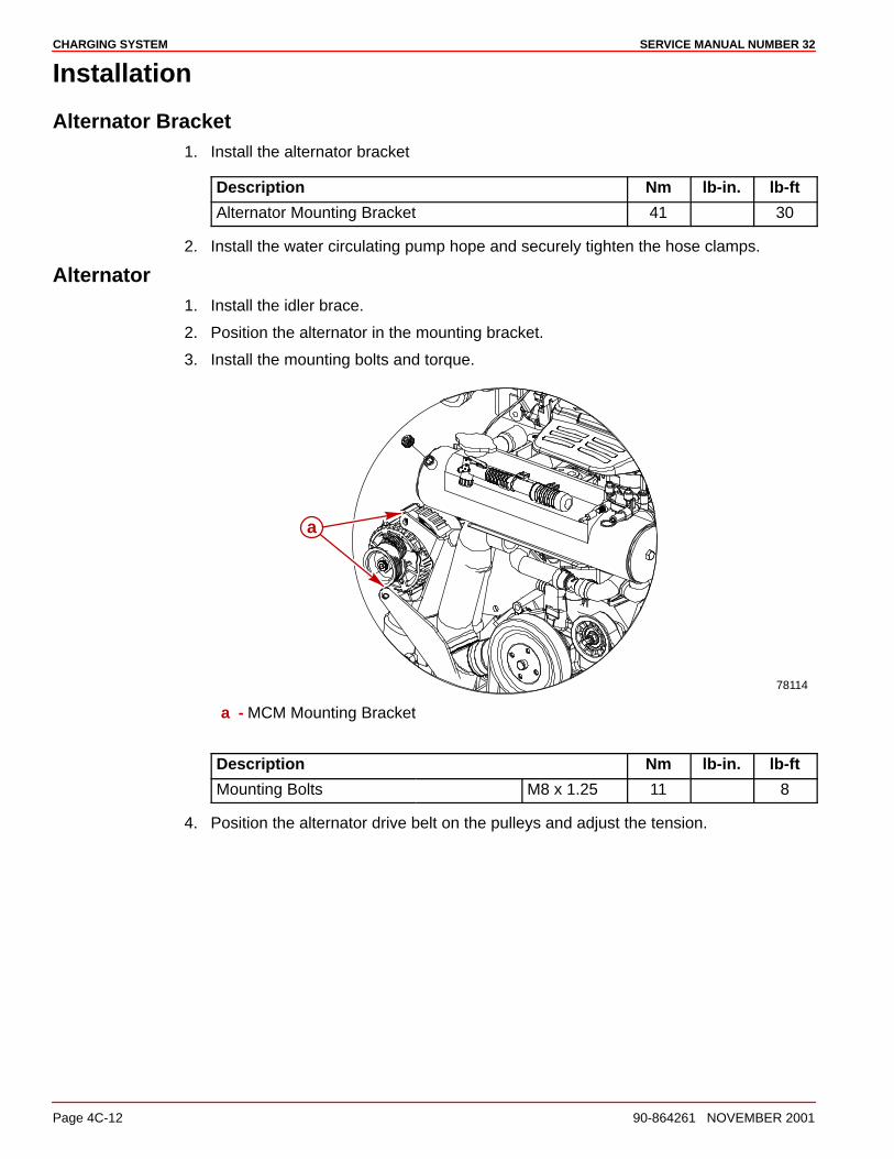
SERVICE MANUAL NUMBER 32CHARGING SYSTEM
Page 4C-12 90-864261 NOVEMBER 2001
Installation
Alternator Bracket1. Install the alternator bracket
Description Nm lb-in. lb-ft
Alternator Mounting Bracket 41 30
2. Install the water circulating pump hope and securely tighten the hose clamps.
Alternator1. Install the idler brace.
2. Position the alternator in the mounting bracket.
3. Install the mounting bolts and torque.
78114
a
a - MCM Mounting Bracket
Description Nm lb-in. lb-ft
Mounting Bolts M8 x 1.25 11 8
4. Position the alternator drive belt on the pulleys and adjust the tension.
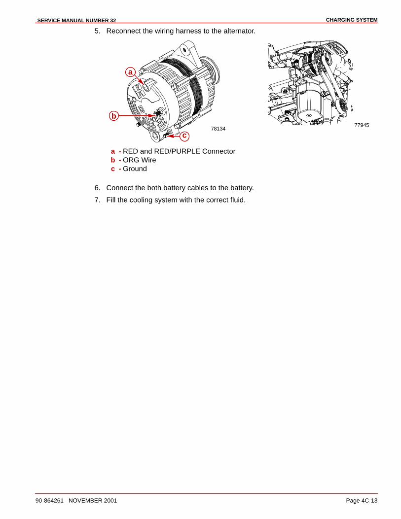
CHARGING SYSTEMSERVICE MANUAL NUMBER 32
90-864261 NOVEMBER 2001 Page 4C-13
5. Reconnect the wiring harness to the alternator.
7813477945
a
c
b
a - RED and RED/PURPLE Connectorb - ORG Wirec - Ground
6. Connect the both battery cables to the battery.
7. Fill the cooling system with the correct fluid.
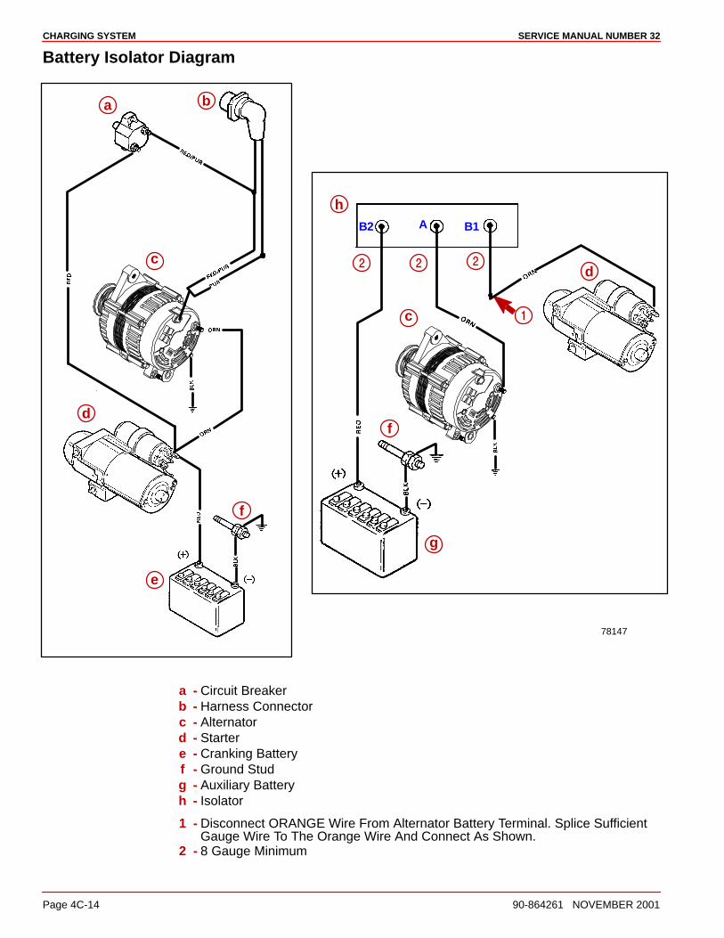
SERVICE MANUAL NUMBER 32CHARGING SYSTEM
Page 4C-14 90-864261 NOVEMBER 2001
Battery Isolator Diagram
78147
a b
c
d
e
f
c
d
g
f
h
�
���
AB B2 1
a - Circuit Breakerb - Harness Connectorc - Alternatord - Startere - Cranking Batteryf - Ground Studg - Auxiliary Batteryh - Isolator
1 - Disconnect ORANGE Wire From Alternator Battery Terminal. Splice SufficientGauge Wire To The Orange Wire And Connect As Shown.
2 - 8 Gauge Minimum
4D
WIRING DIAGRAMSSERVICE MANUAL NUMBER 32
90-864261 NOVEMBER 2001 Page 4D-1
ELECTRICAL SYSTEMSection 4D - Wiring Diagrams
Table of Contents
Instrumentation 4D-2. . . . . . . . . . . . . . . . . . . . . Single Station Installations - Typical 4D-2.
Power Trim System 4D-4. . . . . . . . . . . . . . . . . .
MerCathode System Wiring Diagram 4D-5. . Wiring Diagrams 4D-6. . . . . . . . . . . . . . . . . . . .
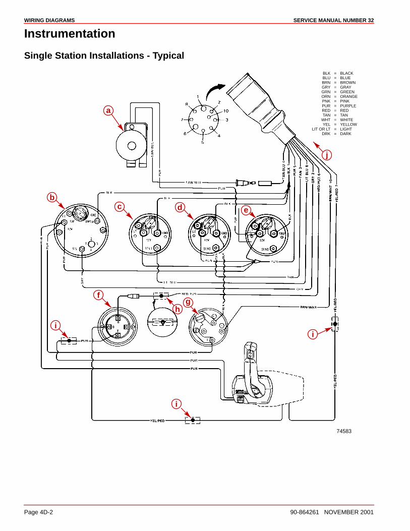
SERVICE MANUAL NUMBER 32WIRING DIAGRAMS
Page 4D-2 90-864261 NOVEMBER 2001
Instrumentation
Single Station Installations - Typical
BLK = BLACKBLU = BLUEBRN = BROWNGRY = GRAYGRN = GREENORN = ORANGEPNK = PINKPUR = PURPLERED = REDTAN = TAN
WHT = WHITEYEL = YELLOW
LIT OR LT = LIGHTDRK = DARK
74583
f
h
i
i
i
a
bc d e
j
g
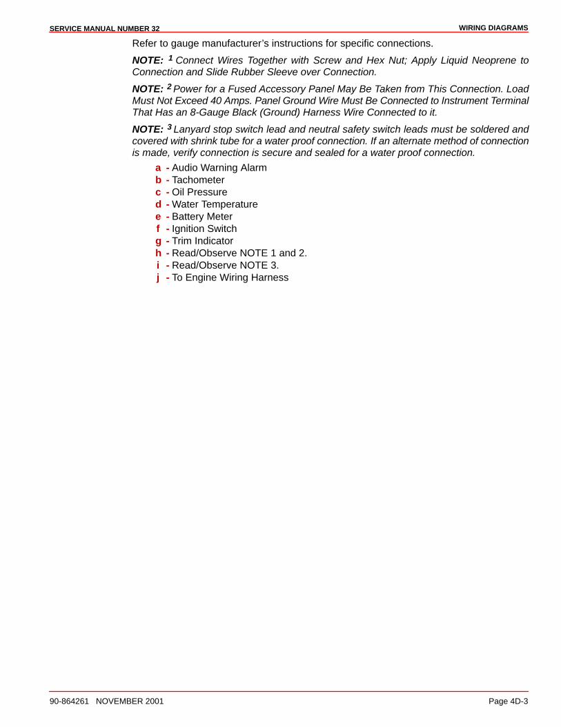
WIRING DIAGRAMSSERVICE MANUAL NUMBER 32
90-864261 NOVEMBER 2001 Page 4D-3
Refer to gauge manufacturer’s instructions for specific connections.
NOTE: 1 Connect Wires Together with Screw and Hex Nut; Apply Liquid Neoprene toConnection and Slide Rubber Sleeve over Connection.
NOTE: 2 Power for a Fused Accessory Panel May Be Taken from This Connection. LoadMust Not Exceed 40 Amps. Panel Ground Wire Must Be Connected to Instrument TerminalThat Has an 8-Gauge Black (Ground) Harness Wire Connected to it.
NOTE: 3 Lanyard stop switch lead and neutral safety switch leads must be soldered andcovered with shrink tube for a water proof connection. If an alternate method of connectionis made, verify connection is secure and sealed for a water proof connection.
a - Audio Warning Alarmb - Tachometerc - Oil Pressured - Water Temperaturee - Battery Meterf - Ignition Switchg - Trim Indicatorh - Read/Observe NOTE 1 and 2.i - Read/Observe NOTE 3.j - To Engine Wiring Harness
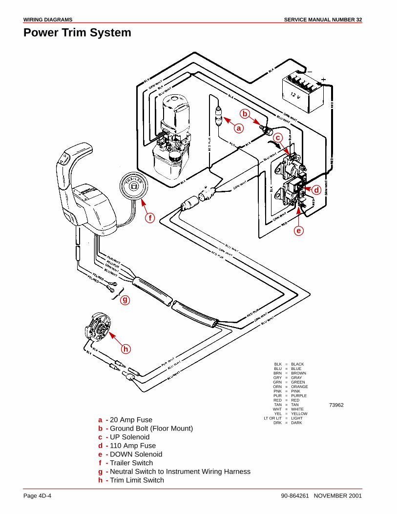
SERVICE MANUAL NUMBER 32WIRING DIAGRAMS
Page 4D-4 90-864261 NOVEMBER 2001
Power Trim System
73962
BLK = BLACKBLU = BLUEBRN = BROWNGRY = GRAYGRN = GREENORN = ORANGEPNK = PINKPUR = PURPLERED = REDTAN = TAN
WHT = WHITEYEL = YELLOW
LT OR LIT = LIGHTDRK = DARK
b
c
d
e
f
g
h
a
a - 20 Amp Fuseb - Ground Bolt (Floor Mount)c - UP Solenoidd - 110 Amp Fusee - DOWN Solenoidf - Trailer Switchg - Neutral Switch to Instrument Wiring Harnessh - Trim Limit Switch
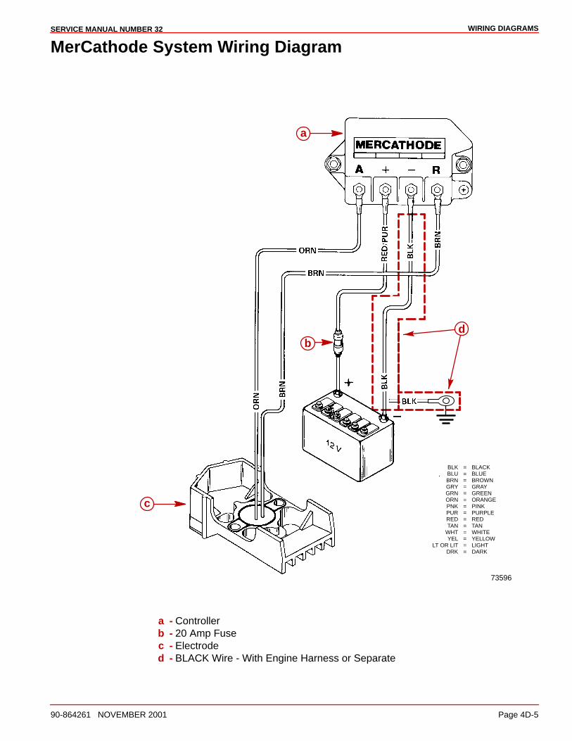
WIRING DIAGRAMSSERVICE MANUAL NUMBER 32
90-864261 NOVEMBER 2001 Page 4D-5
MerCathode System Wiring Diagram
a
b
c
73596
BLK = BLACKBLU = BLUEBRN = BROWNGRY = GRAYGRN = GREENORN = ORANGEPNK = PINKPUR = PURPLERED = REDTAN = TAN
WHT = WHITEYEL = YELLOW
LT OR LIT = LIGHTDRK = DARK
d
a - Controllerb - 20 Amp Fusec - Electroded - BLACK Wire - With Engine Harness or Separate
SERVICE MANUAL NUMBER 32WIRING DIAGRAMS
Page 4D-6 90-864261 NOVEMBER 2001
Wiring Diagrams
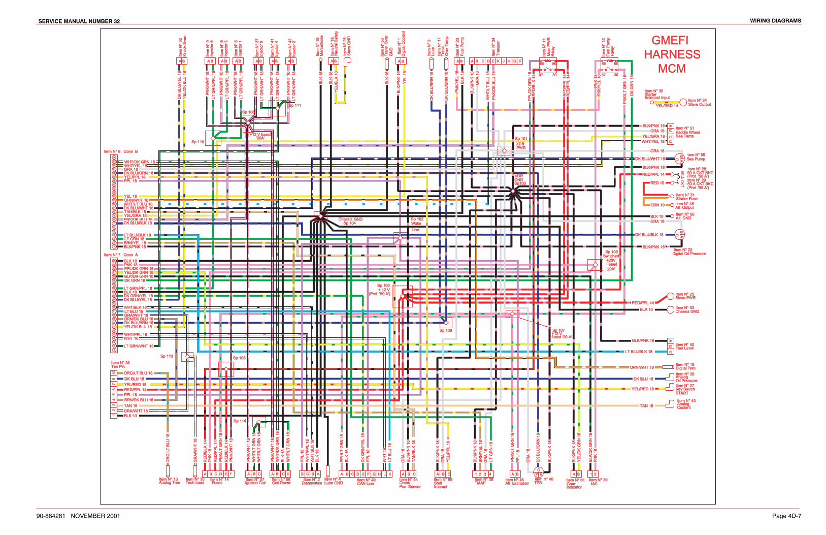
wiring@diagramsservice@manual@number@SR
YPMXVTRVQ@@@nov@@ember@RPPQ pƒ‰‡@TdMW

service@manual@number@SRwiring@diagrams
pƒ‰‡@TdMX YPMXVTRVQ@@@november@RPPQ
this@page@is@intentionally@blank
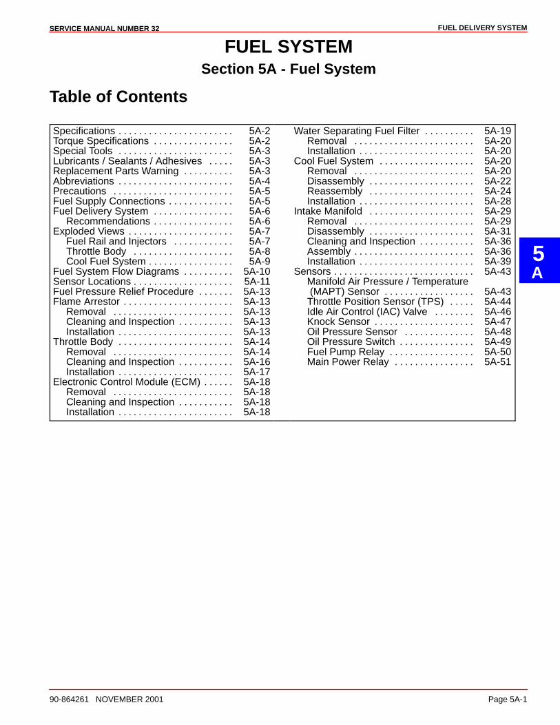
5A
FUEL DELIVERY SYSTEMSERVICE MANUAL NUMBER 32
90-864261 NOVEMBER 2001 Page 5A-1
FUEL SYSTEMSection 5A - Fuel System
Table of Contents
Specifications 5A-2. . . . . . . . . . . . . . . . . . . . . . . Torque Specifications 5A-2. . . . . . . . . . . . . . . . Special Tools 5A-3. . . . . . . . . . . . . . . . . . . . . . . Lubricants / Sealants / Adhesives 5A-3. . . . . Replacement Parts Warning 5A-3. . . . . . . . . . Abbreviations 5A-4. . . . . . . . . . . . . . . . . . . . . . . Precautions 5A-5. . . . . . . . . . . . . . . . . . . . . . . . Fuel Supply Connections 5A-5. . . . . . . . . . . . . Fuel Delivery System 5A-6. . . . . . . . . . . . . . . .
Recommendations 5A-6. . . . . . . . . . . . . . . . Exploded Views 5A-7. . . . . . . . . . . . . . . . . . . . .
Fuel Rail and Injectors 5A-7. . . . . . . . . . . . Throttle Body 5A-8. . . . . . . . . . . . . . . . . . . . Cool Fuel System 5A-9. . . . . . . . . . . . . . . . .
Fuel System Flow Diagrams 5A-10. . . . . . . . . . Sensor Locations 5A-11. . . . . . . . . . . . . . . . . . . . Fuel Pressure Relief Procedure 5A-13. . . . . . . Flame Arrestor 5A-13. . . . . . . . . . . . . . . . . . . . . .
Removal 5A-13. . . . . . . . . . . . . . . . . . . . . . . . Cleaning and Inspection 5A-13. . . . . . . . . . . Installation 5A-13. . . . . . . . . . . . . . . . . . . . . . .
Throttle Body 5A-14. . . . . . . . . . . . . . . . . . . . . . . Removal 5A-14. . . . . . . . . . . . . . . . . . . . . . . . Cleaning and Inspection 5A-16. . . . . . . . . . . Installation 5A-17. . . . . . . . . . . . . . . . . . . . . . .
Electronic Control Module (ECM) 5A-18. . . . . . Removal 5A-18. . . . . . . . . . . . . . . . . . . . . . . . Cleaning and Inspection 5A-18. . . . . . . . . . . Installation 5A-18. . . . . . . . . . . . . . . . . . . . . . .
Water Separating Fuel Filter 5A-19. . . . . . . . . . Removal 5A-20. . . . . . . . . . . . . . . . . . . . . . . . Installation 5A-20. . . . . . . . . . . . . . . . . . . . . . .
Cool Fuel System 5A-20. . . . . . . . . . . . . . . . . . . Removal 5A-20. . . . . . . . . . . . . . . . . . . . . . . . Disassembly 5A-22. . . . . . . . . . . . . . . . . . . . . Reassembly 5A-24. . . . . . . . . . . . . . . . . . . . . Installation 5A-28. . . . . . . . . . . . . . . . . . . . . . .
Intake Manifold 5A-29. . . . . . . . . . . . . . . . . . . . . Removal 5A-29. . . . . . . . . . . . . . . . . . . . . . . . Disassembly 5A-31. . . . . . . . . . . . . . . . . . . . . Cleaning and Inspection 5A-36. . . . . . . . . . . Assembly 5A-36. . . . . . . . . . . . . . . . . . . . . . . . Installation 5A-39. . . . . . . . . . . . . . . . . . . . . . .
Sensors 5A-43. . . . . . . . . . . . . . . . . . . . . . . . . . . . Manifold Air Pressure / Temperature (MAPT) Sensor 5A-43. . . . . . . . . . . . . . . . . . Throttle Position Sensor (TPS) 5A-44. . . . . Idle Air Control (IAC) Valve 5A-46. . . . . . . . Knock Sensor 5A-47. . . . . . . . . . . . . . . . . . . . Oil Pressure Sensor 5A-48. . . . . . . . . . . . . . Oil Pressure Switch 5A-49. . . . . . . . . . . . . . . Fuel Pump Relay 5A-50. . . . . . . . . . . . . . . . . Main Power Relay 5A-51. . . . . . . . . . . . . . . .
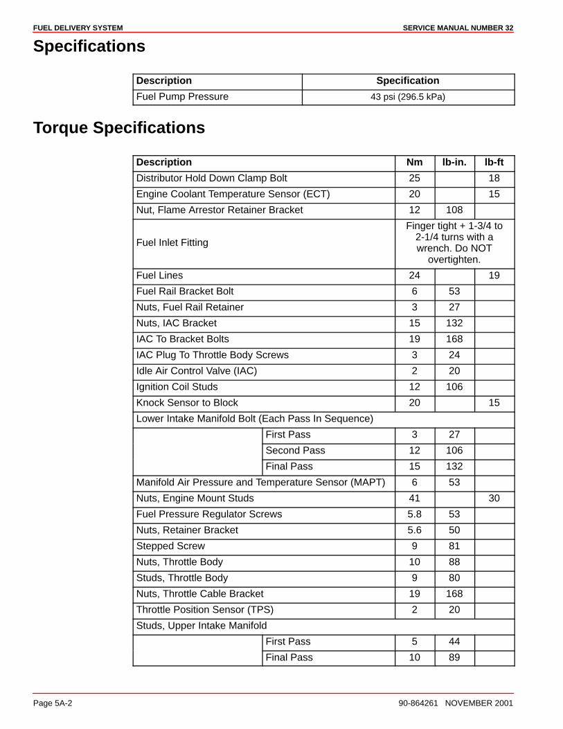
FUEL DELIVERY SYSTEM SERVICE MANUAL NUMBER 32
Page 5A-2 90-864261 NOVEMBER 2001
Specifications
Description Specification
Fuel Pump Pressure 43 psi (296.5 kPa)
Torque Specifications
Description Nm lb-in. lb-ft
Distributor Hold Down Clamp Bolt 25 18
Engine Coolant Temperature Sensor (ECT) 20 15
Nut, Flame Arrestor Retainer Bracket 12 108
Fuel Inlet Fitting
Finger tight + 1-3/4 to2-1/4 turns with awrench. Do NOT
overtighten.
Fuel Lines 24 19
Fuel Rail Bracket Bolt 6 53
Nuts, Fuel Rail Retainer 3 27
Nuts, IAC Bracket 15 132
IAC To Bracket Bolts 19 168
IAC Plug To Throttle Body Screws 3 24
Idle Air Control Valve (IAC) 2 20
Ignition Coil Studs 12 106
Knock Sensor to Block 20 15
Lower Intake Manifold Bolt (Each Pass In Sequence)
First Pass 3 27
Second Pass 12 106
Final Pass 15 132
Manifold Air Pressure and Temperature Sensor (MAPT) 6 53
Nuts, Engine Mount Studs 41 30
Fuel Pressure Regulator Screws 5.8 53
Nuts, Retainer Bracket 5.6 50
Stepped Screw 9 81
Nuts, Throttle Body 10 88
Studs, Throttle Body 9 80
Nuts, Throttle Cable Bracket 19 168
Throttle Position Sensor (TPS) 2 20
Studs, Upper Intake Manifold
First Pass 5 44
Final Pass 10 89
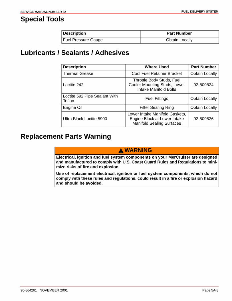
FUEL DELIVERY SYSTEMSERVICE MANUAL NUMBER 32
90-864261 NOVEMBER 2001 Page 5A-3
Special Tools
Description Part Number
Fuel Pressure Gauge Obtain Locally
Lubricants / Sealants / Adhesives
Description Where Used Part Number
Thermal Grease Cool Fuel Retainer Bracket Obtain Locally
Loctite 242Throttle Body Studs, Fuel
Cooler Mounting Studs, LowerIntake Manifold Bolts
92-809824
Loctite 592 Pipe Sealant WithTeflon Fuel Fittings Obtain Locally
Engine Oil Filter Sealing Ring Obtain Locally
Ultra Black Loctite 5900Lower Intake Manifold Gaskets,Engine Block at Lower Intake
Manifold Sealing Surfaces92-809826
Replacement Parts Warning
WARNINGElectrical, ignition and fuel system components on your MerCruiser are designedand manufactured to comply with U.S. Coast Guard Rules and Regulations to mini-mize risks of fire and explosion.
Use of replacement electrical, ignition or fuel system components, which do notcomply with these rules and regulations, could result in a fire or explosion hazardand should be avoided.
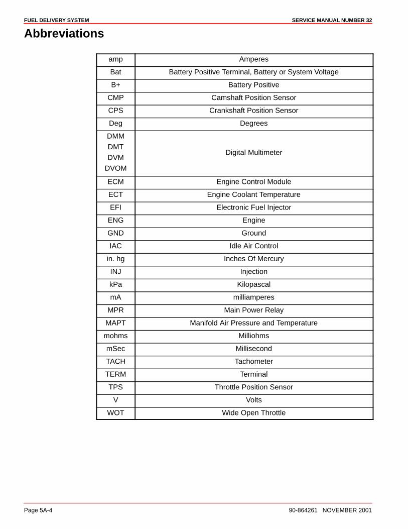
FUEL DELIVERY SYSTEM SERVICE MANUAL NUMBER 32
Page 5A-4 90-864261 NOVEMBER 2001
Abbreviations
amp Amperes
Bat Battery Positive Terminal, Battery or System Voltage
B+ Battery Positive
CMP Camshaft Position Sensor
CPS Crankshaft Position Sensor
Deg Degrees
DMM
DMT
DVM
DVOM
Digital Multimeter
ECM Engine Control Module
ECT Engine Coolant Temperature
EFI Electronic Fuel Injector
ENG Engine
GND Ground
IAC Idle Air Control
in. hg Inches Of Mercury
INJ Injection
kPa Kilopascal
mA milliamperes
MPR Main Power Relay
MAPT Manifold Air Pressure and Temperature
mohms Milliohms
mSec Millisecond
TACH Tachometer
TERM Terminal
TPS Throttle Position Sensor
V Volts
WOT Wide Open Throttle

FUEL DELIVERY SYSTEMSERVICE MANUAL NUMBER 32
90-864261 NOVEMBER 2001 Page 5A-5
Precautions
WARNINGAvoid personal injury or death and power package damage from an electricalshock, fire or explosion. Always disconnect both battery cables from the batterybefore servicing the power package.
WARNINGBe careful when changing fuel system components; gasoline is extremelyflammable and highly explosive under certain conditions. Be sure that ignition keyis OFF. Do NOT smoke or allow sources of spark or flame in the area whilechanging fuel filters. Wipe up any spilled fuel immediately.
WARNINGMake sure that no fuel leaks exist before closing engine hatch.
CAUTIONDo NOT operate engine without cooling water being supplied to seawater pickuppump or pump impeller will be damaged and subsequent overheating damage mayresult.
WARNINGFuel vapors can be present in the engine compartment. Avoid injury or powerpackage damage caused by fuel vapors or explosion. Always ventilate the enginecompartment prior to servicing the power package.
Fuel Supply Connections
WARNINGAvoid gasoline fire or explosion. Improper installation of brass fittings or plugs intofuel pump or fuel filter base can crack casting and/or cause a fuel leak.
• Apply #592 Loctite Pipe Sealant with Teflon to threads of brass fitting or plug. DoNOT use teflon tape.
• Thread brass fitting or plug into fuel pump or fuel filter base until finger tight.
• Tighten fitting or plug an additional 1-3/4 to 2-1/4 turns using a wrench. Do NOTovertighten.
• Install fuel line. To prevent overtightening, hold brass fitting with suitablewrench and tighten fuel line connectors securely.
• Check for fuel leaks.

FUEL DELIVERY SYSTEM SERVICE MANUAL NUMBER 32
Page 5A-6 90-864261 NOVEMBER 2001
Fuel Delivery System
Recommendations
WARNINGBoating standards (NMMA, ABYC, etc.) and Coast Guard regulations must beadhered to when installing fuel delivery system.
The Fuel Tank is an integrated component of the boat. Refer to the special information onservice and maintenance, which you have received from the tank or boat manufacturer.
NOTE: On Ski Boat Applications: If during testing for a particular application, youexperience fuel starvation in sharp high speed turns, baffles or a fuel sump may be neededin the tank to help correct this condition.
All fuel lines must be well secured. The holes where the lines go through the bulkheadsshould be carefully rounded off or protected with rubber grommets. This prevents damageto the lines from abrasion.
The following, but not limited to the following, additional fuel connection related points,applying to all engines unless otherwise stated, must be considered. Refer to boatingstandards (NMMA, ABYC, etc.) and Coast Guard regulations for complete guidelines.
1. Fuel pickup should be at least 25 mm (1 in.) from the bottom of fuel tank to preventpicking up impurities.
2. Fuel lines used must be Coast Guard approved (USCG Type A1).
3. Diameter of fittings and lines must be smaller than 10 mm (3/8 in.) ID.
4. On Multi-Engine Gasoline Installations: It is best to use a fuel pickup and supply linefor each engine. If a single pickup and line is used, the line must be 13 mm (1/2 in.) IDor larger.
5. Larger diameter (than previously specified) lines and fittings must be used oninstallations requiring long lines or numerous fittings.
6. Fuel lines should be installed free of stress and firmly secured to prevent vibration and/orchafing.
7. Sharp bends in fuel lines should be avoided.
8. A flexible fuel line must be used to connect fuel supply line to fuel inlet fitting on engineto absorb deflection when engine is running.
IMPORTANT: Vacuum reading higher than specified can cause vapor locking withsome of today’s fuels. It can also cause poor engine performance due to fuelstarvation.
9. The maximum measured vacuum at engine fuel inlet must not exceed 6.9 kPa (2 in. Hg)at 650, 3000, WOT and idle rpm.
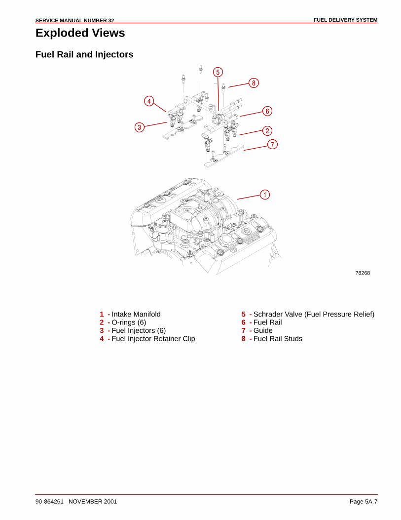
FUEL DELIVERY SYSTEMSERVICE MANUAL NUMBER 32
90-864261 NOVEMBER 2001 Page 5A-7
Exploded Views
Fuel Rail and Injectors
78268
�
�
��
�
�
�
�
1 - Intake Manifold2 - O-rings (6)3 - Fuel Injectors (6)4 - Fuel Injector Retainer Clip
5 - Schrader Valve (Fuel Pressure Relief)6 - Fuel Rail7 - Guide8 - Fuel Rail Studs
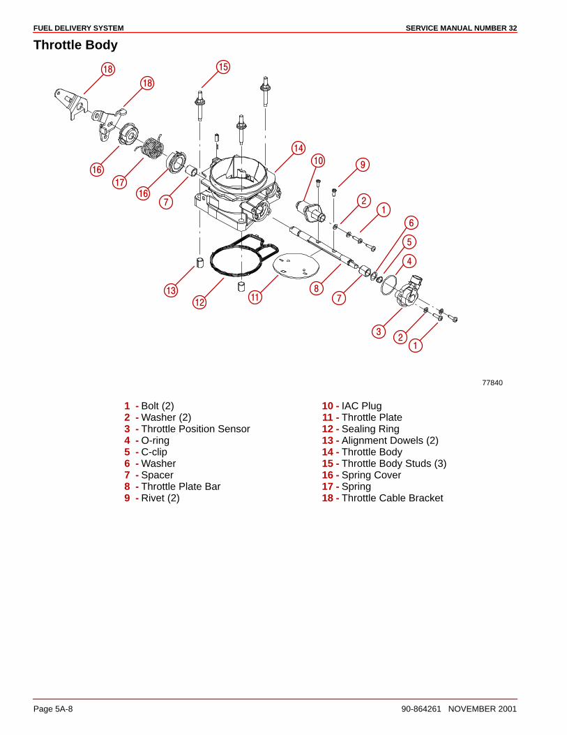
FUEL DELIVERY SYSTEM SERVICE MANUAL NUMBER 32
Page 5A-8 90-864261 NOVEMBER 2001
Throttle Body
77840
�
����
��
��
��
��
��
�
�
�
�
�
�
��
��
�
��
��
��
1 - Bolt (2)2 - Washer (2)3 - Throttle Position Sensor4 - O-ring5 - C-clip6 - Washer7 - Spacer8 - Throttle Plate Bar9 - Rivet (2)
10 - IAC Plug11 - Throttle Plate12 - Sealing Ring13 - Alignment Dowels (2)14 - Throttle Body15 - Throttle Body Studs (3)16 - Spring Cover17 - Spring18 - Throttle Cable Bracket
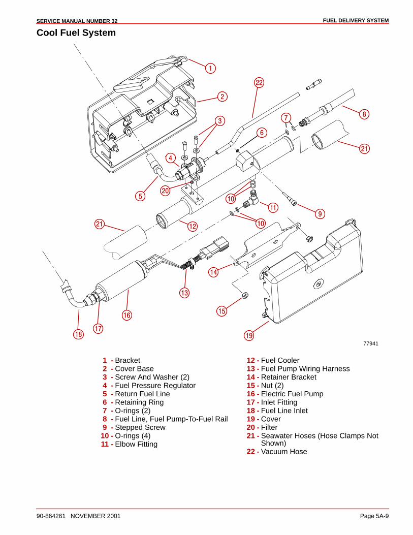
FUEL DELIVERY SYSTEMSERVICE MANUAL NUMBER 32
90-864261 NOVEMBER 2001 Page 5A-9
Cool Fuel System
77941
�
��
��
��
��
����
���� �
�
��
��
�
�
�
�
�
�
��
��
�
1 - Bracket2 - Cover Base3 - Screw And Washer (2)4 - Fuel Pressure Regulator5 - Return Fuel Line6 - Retaining Ring7 - O-rings (2)8 - Fuel Line, Fuel Pump-To-Fuel Rail9 - Stepped Screw
10 - O-rings (4)11 - Elbow Fitting
12 - Fuel Cooler13 - Fuel Pump Wiring Harness14 - Retainer Bracket15 - Nut (2)16 - Electric Fuel Pump17 - Inlet Fitting18 - Fuel Line Inlet19 - Cover20 - Filter21 - Seawater Hoses (Hose Clamps Not
Shown)22 - Vacuum Hose
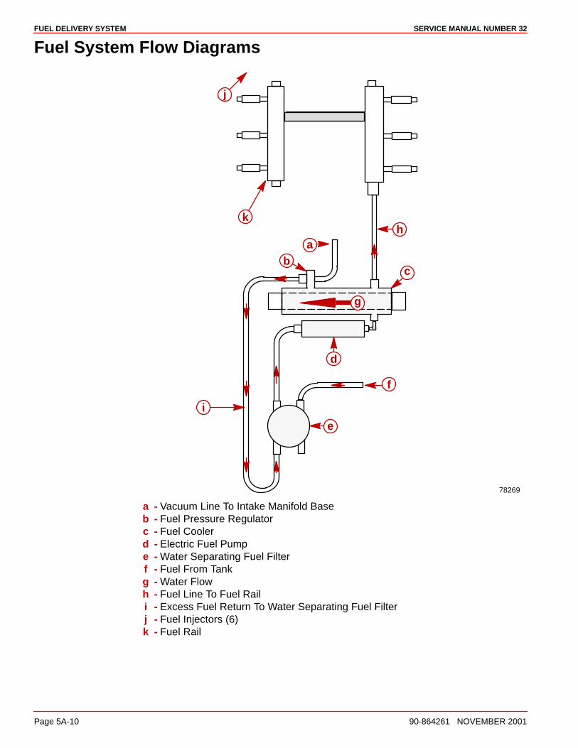
FUEL DELIVERY SYSTEM SERVICE MANUAL NUMBER 32
Page 5A-10 90-864261 NOVEMBER 2001
Fuel System Flow Diagrams
g
78269
ab
c
d
e
f
g
hk
j
i
a - Vacuum Line To Intake Manifold Baseb - Fuel Pressure Regulatorc - Fuel Coolerd - Electric Fuel Pumpe - Water Separating Fuel Filterf - Fuel From Tankg - Water Flowh - Fuel Line To Fuel Raili - Excess Fuel Return To Water Separating Fuel Filterj - Fuel Injectors (6)k - Fuel Rail
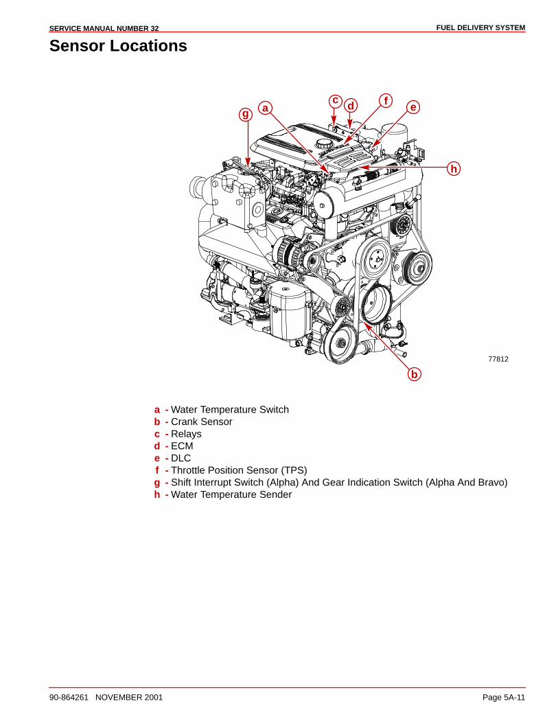
FUEL DELIVERY SYSTEMSERVICE MANUAL NUMBER 32
90-864261 NOVEMBER 2001 Page 5A-11
Sensor Locations
77812
a
b
c d efg
h
a - Water Temperature Switchb - Crank Sensorc - Relaysd - ECMe - DLCf - Throttle Position Sensor (TPS)g - Shift Interrupt Switch (Alpha) And Gear Indication Switch (Alpha And Bravo)h - Water Temperature Sender
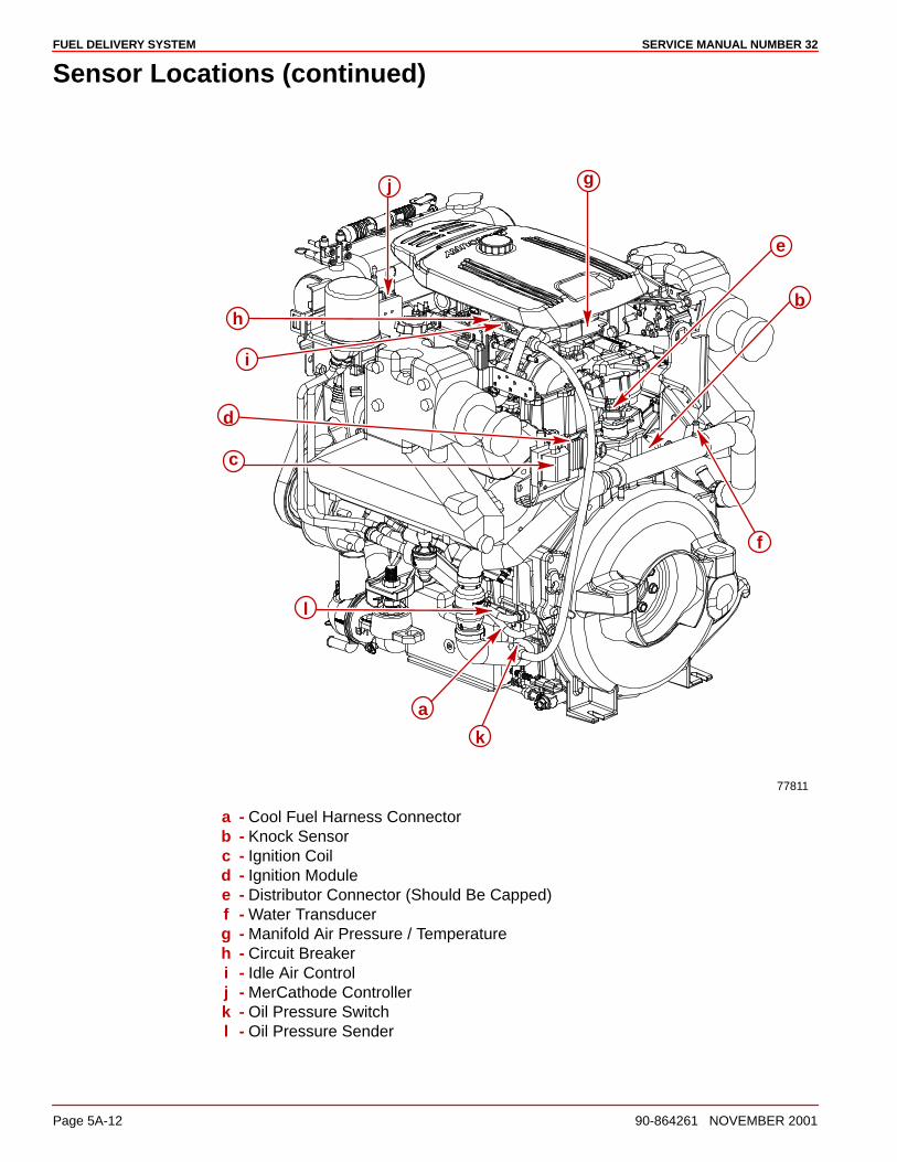
FUEL DELIVERY SYSTEM SERVICE MANUAL NUMBER 32
Page 5A-12 90-864261 NOVEMBER 2001
Sensor Locations (continued)
77811
a
b
c
d
gj
e
h
i
k
l
f
a - Cool Fuel Harness Connectorb - Knock Sensorc - Ignition Coild - Ignition Modulee - Distributor Connector (Should Be Capped)f - Water Transducerg - Manifold Air Pressure / Temperatureh - Circuit Breakeri - Idle Air Controlj - MerCathode Controllerk - Oil Pressure Switchl - Oil Pressure Sender
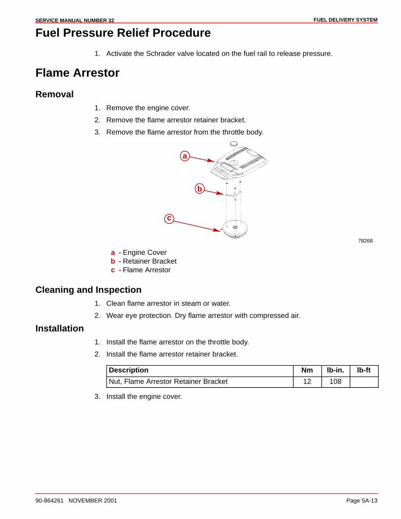
FUEL DELIVERY SYSTEMSERVICE MANUAL NUMBER 32
90-864261 NOVEMBER 2001 Page 5A-13
Fuel Pressure Relief Procedure
1. Activate the Schrader valve located on the fuel rail to release pressure.
Flame Arrestor
Removal1. Remove the engine cover.
2. Remove the flame arrestor retainer bracket.
3. Remove the flame arrestor from the throttle body.
78268
a
b
c
a - Engine Coverb - Retainer Bracketc - Flame Arrestor
Cleaning and Inspection1. Clean flame arrestor in steam or water.
2. Wear eye protection. Dry flame arrestor with compressed air.
Installation1. Install the flame arrestor on the throttle body.
2. Install the flame arrestor retainer bracket.
Description Nm lb-in. lb-ft
Nut, Flame Arrestor Retainer Bracket 12 108
3. Install the engine cover.
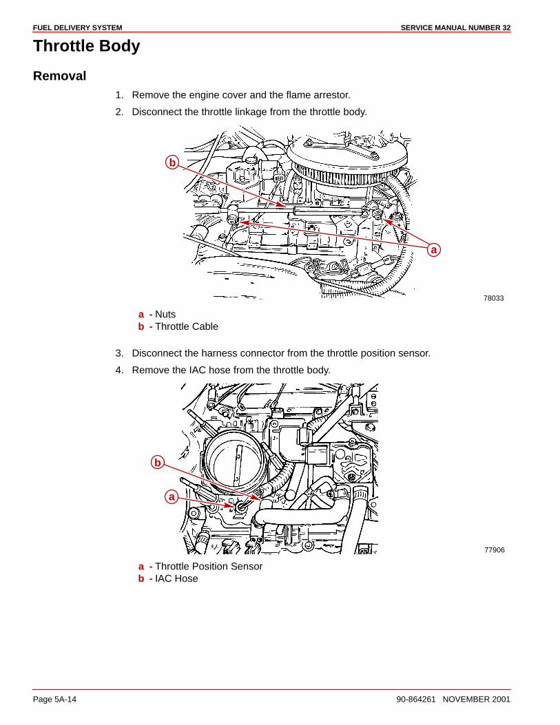
FUEL DELIVERY SYSTEM SERVICE MANUAL NUMBER 32
Page 5A-14 90-864261 NOVEMBER 2001
Throttle Body
Removal1. Remove the engine cover and the flame arrestor.
2. Disconnect the throttle linkage from the throttle body.
78033
a
b
a - Nutsb - Throttle Cable
3. Disconnect the harness connector from the throttle position sensor.
4. Remove the IAC hose from the throttle body.
77906
a
b
a - Throttle Position Sensorb - IAC Hose
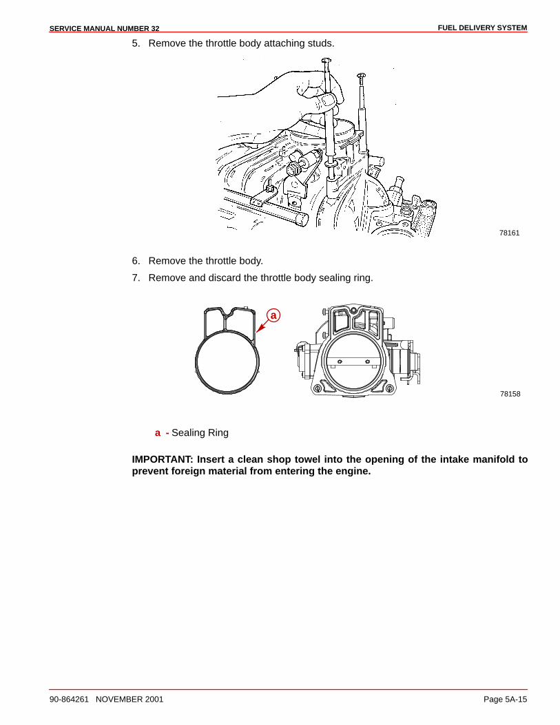
FUEL DELIVERY SYSTEMSERVICE MANUAL NUMBER 32
90-864261 NOVEMBER 2001 Page 5A-15
5. Remove the throttle body attaching studs.
78161
6. Remove the throttle body.
7. Remove and discard the throttle body sealing ring.
78158
a
a - Sealing Ring
IMPORTANT: Insert a clean shop towel into the opening of the intake manifold toprevent foreign material from entering the engine.
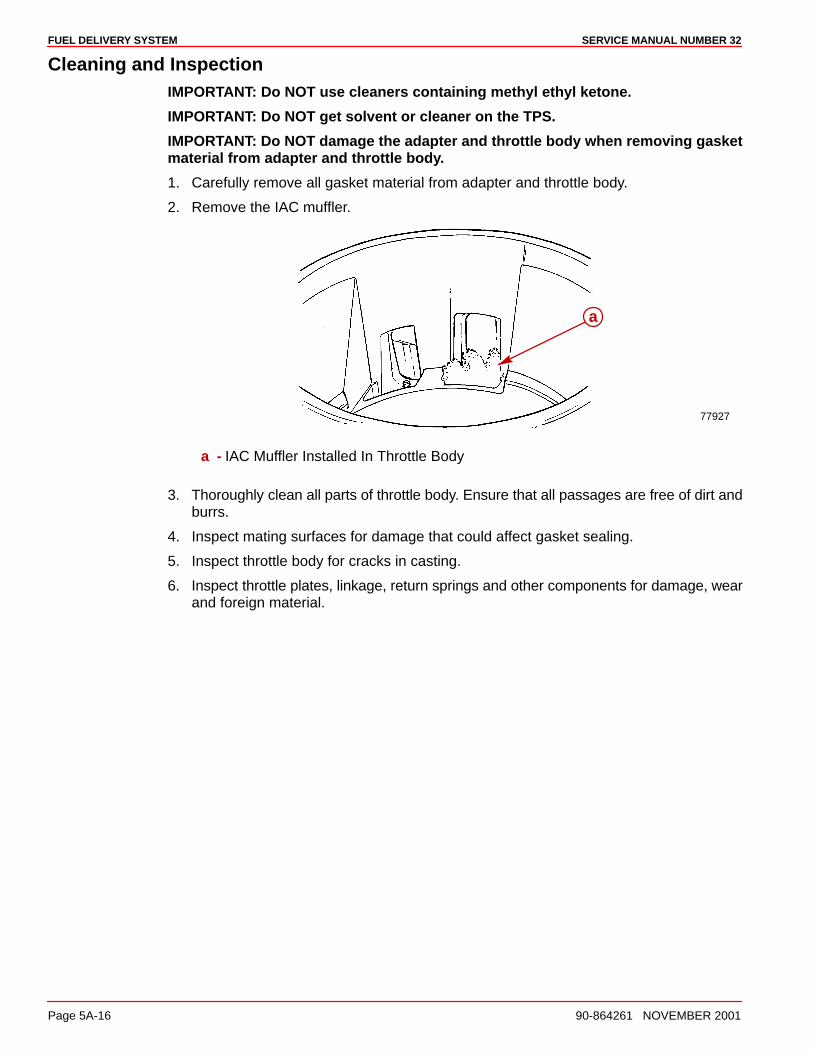
FUEL DELIVERY SYSTEM SERVICE MANUAL NUMBER 32
Page 5A-16 90-864261 NOVEMBER 2001
Cleaning and InspectionIMPORTANT: Do NOT use cleaners containing methyl ethyl ketone.
IMPORTANT: Do NOT get solvent or cleaner on the TPS.
IMPORTANT: Do NOT damage the adapter and throttle body when removing gasketmaterial from adapter and throttle body.
1. Carefully remove all gasket material from adapter and throttle body.
2. Remove the IAC muffler.
77927
a
a - IAC Muffler Installed In Throttle Body
3. Thoroughly clean all parts of throttle body. Ensure that all passages are free of dirt andburrs.
4. Inspect mating surfaces for damage that could affect gasket sealing.
5. Inspect throttle body for cracks in casting.
6. Inspect throttle plates, linkage, return springs and other components for damage, wearand foreign material.
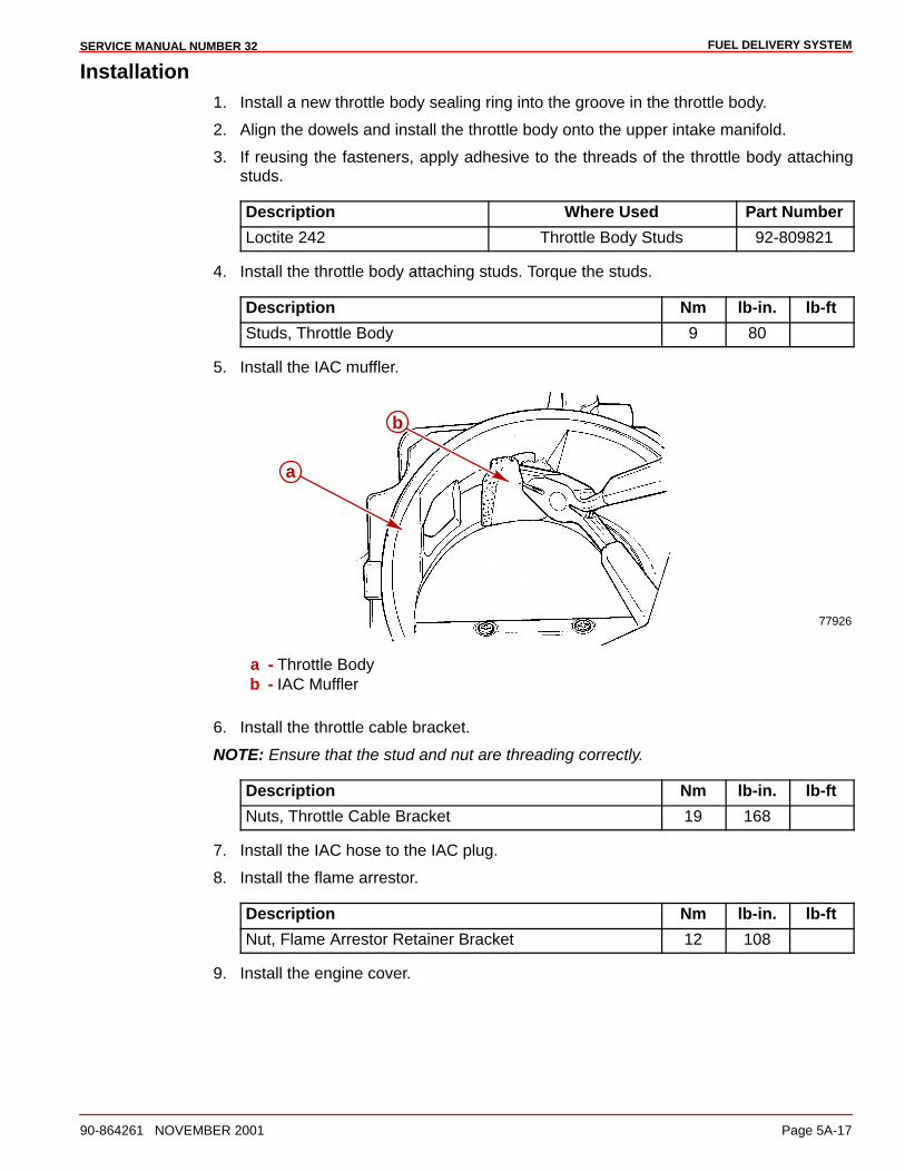
FUEL DELIVERY SYSTEMSERVICE MANUAL NUMBER 32
90-864261 NOVEMBER 2001 Page 5A-17
Installation1. Install a new throttle body sealing ring into the groove in the throttle body.
2. Align the dowels and install the throttle body onto the upper intake manifold.
3. If reusing the fasteners, apply adhesive to the threads of the throttle body attachingstuds.
Description Where Used Part Number
Loctite 242 Throttle Body Studs 92-809821
4. Install the throttle body attaching studs. Torque the studs.
Description Nm lb-in. lb-ft
Studs, Throttle Body 9 80
5. Install the IAC muffler.
77926
b
a
a - Throttle Bodyb - IAC Muffler
6. Install the throttle cable bracket.
NOTE: Ensure that the stud and nut are threading correctly.
Description Nm lb-in. lb-ft
Nuts, Throttle Cable Bracket 19 168
7. Install the IAC hose to the IAC plug.
8. Install the flame arrestor.
Description Nm lb-in. lb-ft
Nut, Flame Arrestor Retainer Bracket 12 108
9. Install the engine cover.
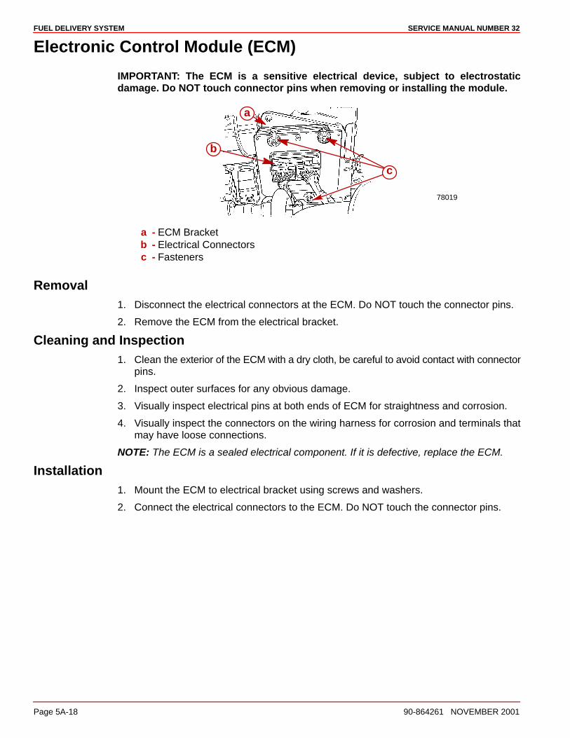
FUEL DELIVERY SYSTEM SERVICE MANUAL NUMBER 32
Page 5A-18 90-864261 NOVEMBER 2001
Electronic Control Module (ECM)
IMPORTANT: The ECM is a sensitive electrical device, subject to electrostaticdamage. Do NOT touch connector pins when removing or installing the module.
78019
a
b
c
a - ECM Bracketb - Electrical Connectorsc - Fasteners
Removal1. Disconnect the electrical connectors at the ECM. Do NOT touch the connector pins.
2. Remove the ECM from the electrical bracket.
Cleaning and Inspection1. Clean the exterior of the ECM with a dry cloth, be careful to avoid contact with connector
pins.
2. Inspect outer surfaces for any obvious damage.
3. Visually inspect electrical pins at both ends of ECM for straightness and corrosion.
4. Visually inspect the connectors on the wiring harness for corrosion and terminals thatmay have loose connections.
NOTE: The ECM is a sealed electrical component. If it is defective, replace the ECM.
Installation1. Mount the ECM to electrical bracket using screws and washers.
2. Connect the electrical connectors to the ECM. Do NOT touch the connector pins.
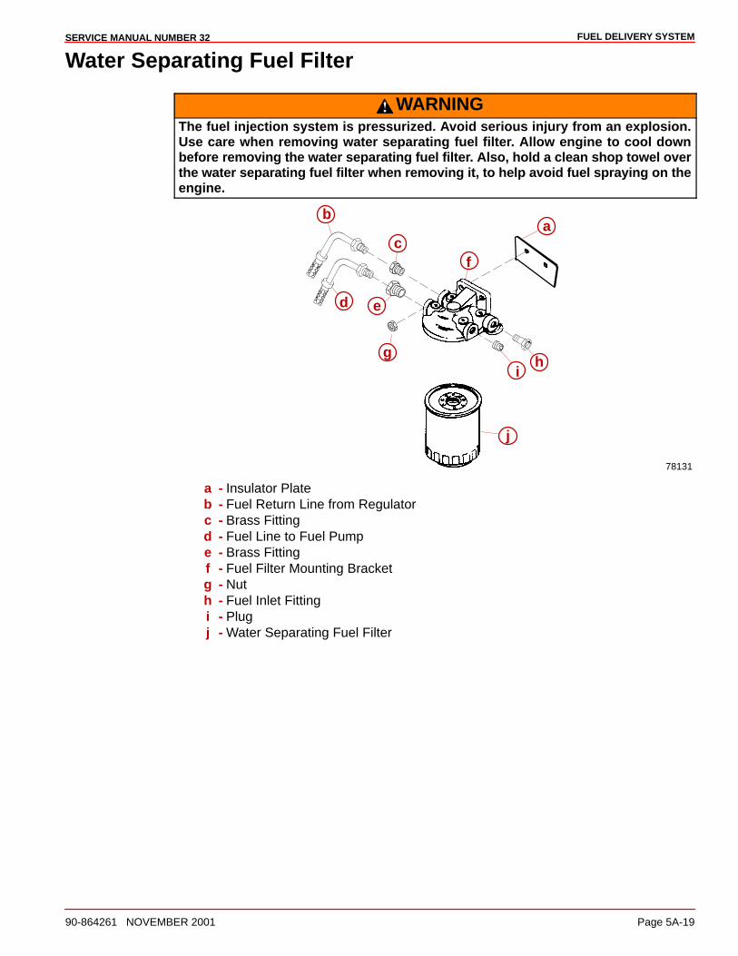
FUEL DELIVERY SYSTEMSERVICE MANUAL NUMBER 32
90-864261 NOVEMBER 2001 Page 5A-19
Water Separating Fuel Filter
WARNINGThe fuel injection system is pressurized. Avoid serious injury from an explosion.Use care when removing water separating fuel filter. Allow engine to cool downbefore removing the water separating fuel filter. Also, hold a clean shop towel overthe water separating fuel filter when removing it, to help avoid fuel spraying on theengine.
ab
c
d e
f
gh
i
j
78131
a - Insulator Plateb - Fuel Return Line from Regulatorc - Brass Fittingd - Fuel Line to Fuel Pumpe - Brass Fittingf - Fuel Filter Mounting Bracketg - Nuth - Fuel Inlet Fittingi - Plugj - Water Separating Fuel Filter

FUEL DELIVERY SYSTEM SERVICE MANUAL NUMBER 32
Page 5A-20 90-864261 NOVEMBER 2001
Removal
WARNINGAvoid injury or death and power package damage from an electrical shock, fire orexplosion. Always disconnect both battery cables from the battery before servicingthe power package.
1. Disconnect both battery cables from the battery.
2. Activate the Schrader valve to relieve fuel pressure.
3. Remove the fuel filter from the base. A filter wrench may be needed.
Installation1. Lubricate sealing ring of new filter with engine oil.
Description Where Used Part Number
Engine Oil Sealing Ring Obtain Locally
2. Install a new filter. Tighten securely by hand.
3. Connect both battery cables to the battery.
4. Supply water to cooling system.
5. Start engine.
6. Check for fuel leaks.
Cool Fuel System
Removal
WARNINGAvoid injury or death and power package damage from an electrical shock, fire orexplosion. Always disconnect both battery cables from the battery before servicingthe power package.
1. Disconnect both battery cables from the battery.
CAUTIONIf boat is to remain in the water, the seacock, if equipped, must remain closed untilengine is to be restarted to prevent water from flowing back into seawater coolingsystem. If boat is not fitted with a seacock, water inlet hose must be disconnectedand plugged to prevent water from flowing into cooling system and/or boat.
2. Close the seacock, if equipped. If boat is not equipped with a seacock, remove and plugthe seawater inlet hose.
3. Drain the seawater system. Refer to SECTION 1B.
4. Disconnect the seawater hoses from the fuel cooler.
IMPORTANT: Plug open ends of fuel line connections to prevent fuel leaks and entryof water or contaminates into lines while working.
5. Close fuel shut off valve, if equipped, and remove the fuel tank inlet line from the waterseparating fuel filter. If boat is not equipped with a fuel tank shut off valve, remove thefuel tank inlet line at the water separating fuel filter and plug the line.
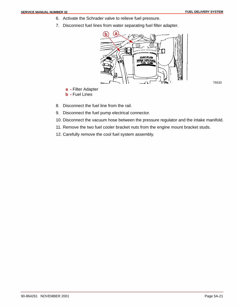
FUEL DELIVERY SYSTEMSERVICE MANUAL NUMBER 32
90-864261 NOVEMBER 2001 Page 5A-21
6. Activate the Schrader valve to relieve fuel pressure.
7. Disconnect fuel lines from water separating fuel filter adapter.
75533
b a
a - Filter Adapterb - Fuel Lines
8. Disconnect the fuel line from the rail.
9. Disconnect the fuel pump electrical connector.
10. Disconnect the vacuum hose between the pressure regulator and the intake manifold.
11. Remove the two fuel cooler bracket nuts from the engine mount bracket studs.
12. Carefully remove the cool fuel system assembly.
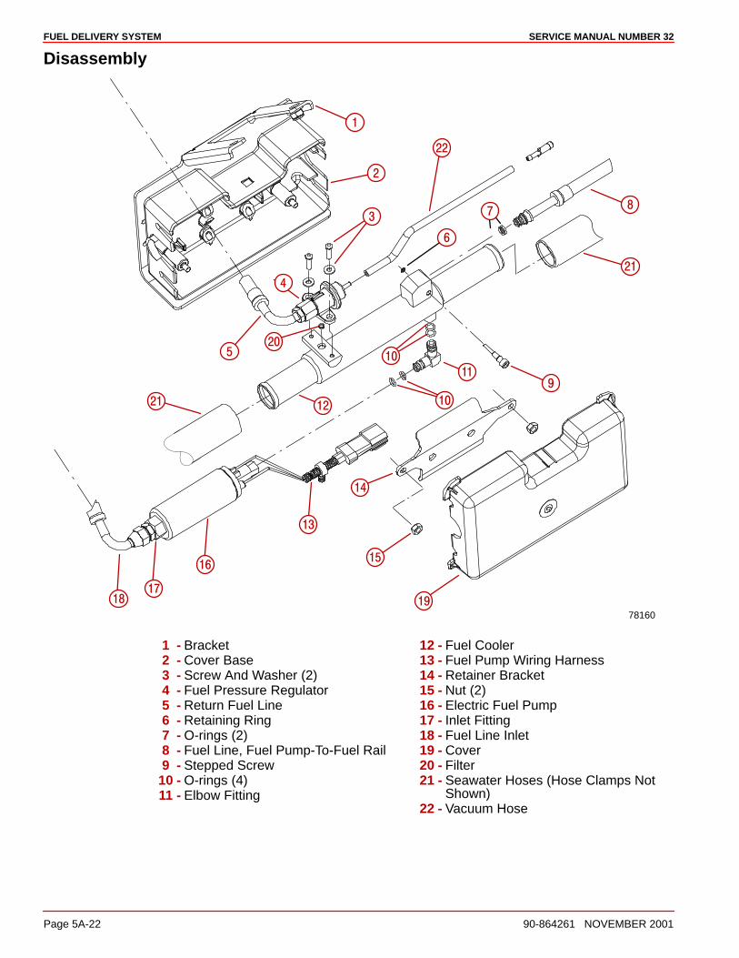
FUEL DELIVERY SYSTEM SERVICE MANUAL NUMBER 32
Page 5A-22 90-864261 NOVEMBER 2001
Disassembly
78160
�
��
��
��
��
����
���� �
�
��
��
�
�
�
�
�
�
��
��
�
1 - Bracket2 - Cover Base3 - Screw And Washer (2)4 - Fuel Pressure Regulator5 - Return Fuel Line6 - Retaining Ring7 - O-rings (2)8 - Fuel Line, Fuel Pump-To-Fuel Rail9 - Stepped Screw
10 - O-rings (4)11 - Elbow Fitting
12 - Fuel Cooler13 - Fuel Pump Wiring Harness14 - Retainer Bracket15 - Nut (2)16 - Electric Fuel Pump17 - Inlet Fitting18 - Fuel Line Inlet19 - Cover20 - Filter21 - Seawater Hoses (Hose Clamps Not
Shown)22 - Vacuum Hose
FUEL DELIVERY SYSTEMSERVICE MANUAL NUMBER 32
90-864261 NOVEMBER 2001 Page 5A-23
NOTE: Retain all fasteners and hardware unless instructed otherwise.
1. Remove the cool fuel system cover.
2. Remove the two nuts from the cool fuel retaining bracket studs.
3. Remove the retainer bracket.
4. Unclip the wiring harness from the cover base.
5. Remove the fuel cooler and the electric fuel pump assembly from the cover base.
IMPORTANT: To prevent loss of the stepped screw used to secure the fuelcooler-to-fuel rail fuel line, a retainer ring is provided. Do not remove the retainer ringor stepped screw.
6. Loosen the stepped screw and remove the fuel line.
7. Hold the fuel line and fuel pump or fuel cooler fittings securely and remove the fuel lines.
8. Disconnect the elbow fitting and fuel pump from the fuel cooler assembly by pullingfirmly.
9. Remove the elbow fitting from the fuel pump by pulling firmly.
10. Hold the fuel line and regulator fittings securely and remove the fuel line.
11. Remove the fuel line fitting from the fuel pressure regulator.
12. Remove the two screws and washers retaining the fuel pressure regulator to the fuelcooler.
13. Remove the regulator.
14. Remove the conical filter from the fuel cooler.
15. Disconnect the vacuum hose from the regulator by pulling firmly.
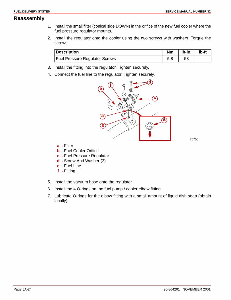
FUEL DELIVERY SYSTEM SERVICE MANUAL NUMBER 32
Page 5A-24 90-864261 NOVEMBER 2001
Reassembly1. Install the small filter (conical side DOWN) in the orifice of the new fuel cooler where the
fuel pressure regulator mounts.
2. Install the regulator onto the cooler using the two screws with washers. Torque thescrews.
Description Nm lb-in. lb-ft
Fuel Pressure Regulator Screws 5.8 53
3. Install the fitting into the regulator. Tighten securely.
4. Connect the fuel line to the regulator. Tighten securely.
75708
e
a
b
f
a
c
d
a - Filterb - Fuel Cooler Orificec - Fuel Pressure Regulatord - Screw And Washer (2)e - Fuel Linef - Fitting
5. Install the vacuum hose onto the regulator.
6. Install the 4 O-rings on the fuel pump / cooler elbow fitting.
7. Lubricate O-rings for the elbow fitting with a small amount of liquid dish soap (obtainlocally).
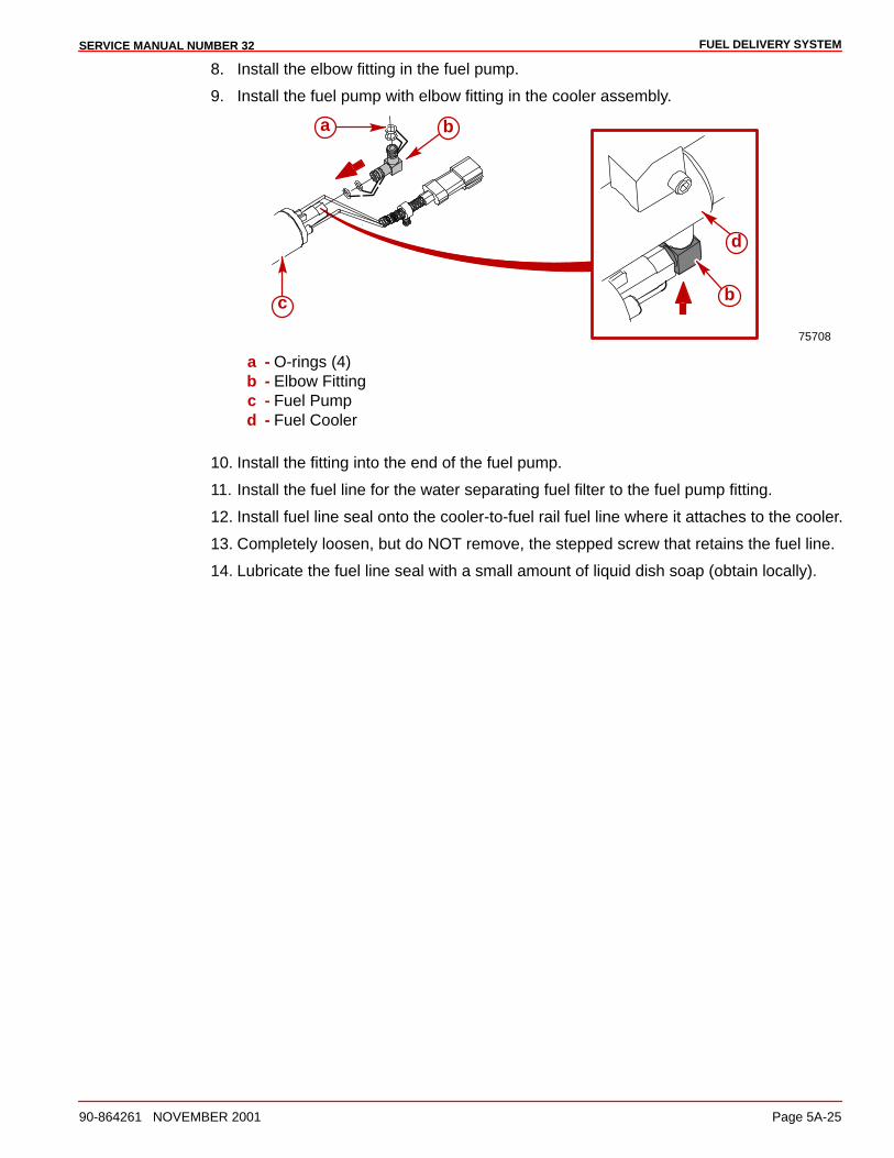
FUEL DELIVERY SYSTEMSERVICE MANUAL NUMBER 32
90-864261 NOVEMBER 2001 Page 5A-25
8. Install the elbow fitting in the fuel pump.
9. Install the fuel pump with elbow fitting in the cooler assembly.
75708
d
bc
a b
a - O-rings (4)b - Elbow Fittingc - Fuel Pumpd - Fuel Cooler
10. Install the fitting into the end of the fuel pump.
11. Install the fuel line for the water separating fuel filter to the fuel pump fitting.
12. Install fuel line seal onto the cooler-to-fuel rail fuel line where it attaches to the cooler.
13. Completely loosen, but do NOT remove, the stepped screw that retains the fuel line.
14. Lubricate the fuel line seal with a small amount of liquid dish soap (obtain locally).
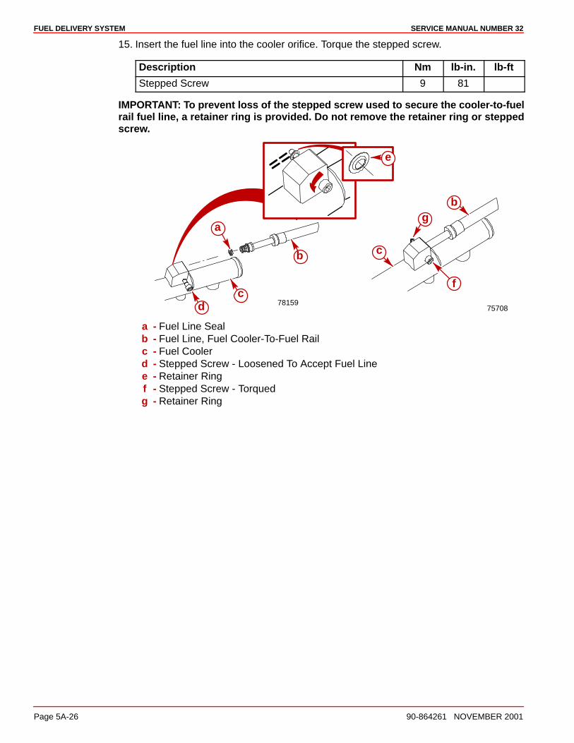
FUEL DELIVERY SYSTEM SERVICE MANUAL NUMBER 32
Page 5A-26 90-864261 NOVEMBER 2001
15. Insert the fuel line into the cooler orifice. Torque the stepped screw.
Description Nm lb-in. lb-ft
Stepped Screw 9 81
IMPORTANT: To prevent loss of the stepped screw used to secure the cooler-to-fuelrail fuel line, a retainer ring is provided. Do not remove the retainer ring or steppedscrew.
78159
e
a
b
dc
75708
b
c
f
g
a - Fuel Line Sealb - Fuel Line, Fuel Cooler-To-Fuel Railc - Fuel Coolerd - Stepped Screw - Loosened To Accept Fuel Linee - Retainer Ringf - Stepped Screw - Torquedg - Retainer Ring
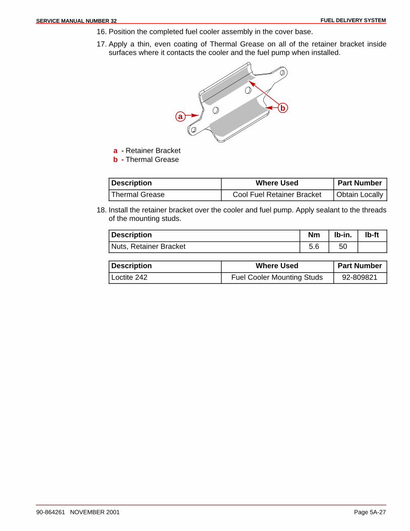
FUEL DELIVERY SYSTEMSERVICE MANUAL NUMBER 32
90-864261 NOVEMBER 2001 Page 5A-27
16. Position the completed fuel cooler assembly in the cover base.
17. Apply a thin, even coating of Thermal Grease on all of the retainer bracket insidesurfaces where it contacts the cooler and the fuel pump when installed.
ab
a - Retainer Bracketb - Thermal Grease
Description Where Used Part Number
Thermal Grease Cool Fuel Retainer Bracket Obtain Locally
18. Install the retainer bracket over the cooler and fuel pump. Apply sealant to the threadsof the mounting studs.
Description Nm lb-in. lb-ft
Nuts, Retainer Bracket 5.6 50
Description Where Used Part Number
Loctite 242 Fuel Cooler Mounting Studs 92-809821
FUEL DELIVERY SYSTEM SERVICE MANUAL NUMBER 32
Page 5A-28 90-864261 NOVEMBER 2001
Installation1. Place the cool fuel assembly on the engine mount studs. Install the two nuts.
Description Nm lb-in. lb-ft
Nuts, Engine Mount Studs 41 30
2. Connect the fuel lines to the fuel filter adapter and tighten securely.
Description Nm lb-in. lb-ft
Fuel Lines 24 19
3. Connect fuel line to the fuel rail.
4. Connect vacuum line to intake manifold.
5. Attach engine harness electrical connector to fuel pump harness connector.
6. Clip fuel pump harness to cool fuel base.
CAUTIONDO NOT operate engine without cooling water being supplied to seawater pickuppump, or pump impeller will be damaged and subsequent overheating damage mayresult.
7. Connect seawater hoses to cool fuel system. Tighten hose clamps securely.
8. Unplug and connect seawater inlet hose. Open seacock, if equipped.
9. Unplug and connect fuel tank inlet line. Tighten hose clamp securely. Open fuel shut offvalve, if equipped.
CAUTIONWhen installing battery, be sure to connect POSITIVE (+) battery cable to POSITIVE(+) battery terminal FIRST, and NEGATIVE (–) battery cable to NEGATIVE (–) batteryterminal LAST. If battery cables are reversed, or connection order is reversed,electrical system damage will result.
10. Clean battery cable clamps and terminals and connect battery cables to the battery.Secure each cable clamp when connecting. Coat terminals with a battery terminalanti-corrosion spray to help retard corrosion.
11. Start the engine; check for fuel and water leaks. Stop the engine immediately if any leaksexist. Make necessary corrections.
12. Install cool fuel system cover.
WARNINGEnsure that no leaks exist before closing engine hatch.
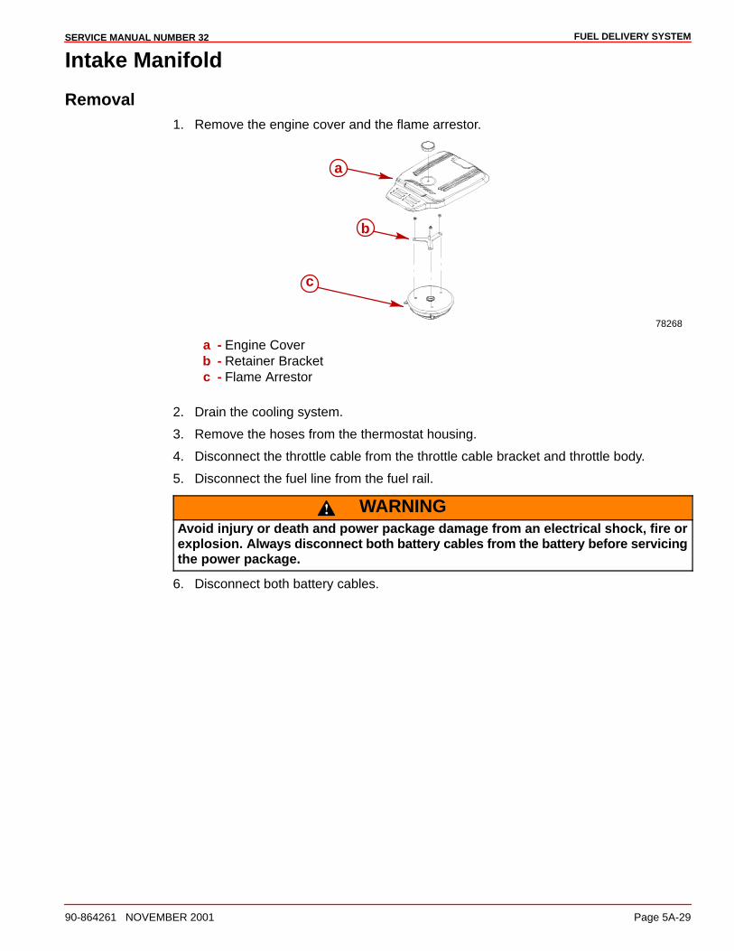
FUEL DELIVERY SYSTEMSERVICE MANUAL NUMBER 32
90-864261 NOVEMBER 2001 Page 5A-29
Intake Manifold
Removal1. Remove the engine cover and the flame arrestor.
78268
a
b
c
a - Engine Coverb - Retainer Bracketc - Flame Arrestor
2. Drain the cooling system.
3. Remove the hoses from the thermostat housing.
4. Disconnect the throttle cable from the throttle cable bracket and throttle body.
5. Disconnect the fuel line from the fuel rail.
WARNINGAvoid injury or death and power package damage from an electrical shock, fire orexplosion. Always disconnect both battery cables from the battery before servicingthe power package.
6. Disconnect both battery cables.
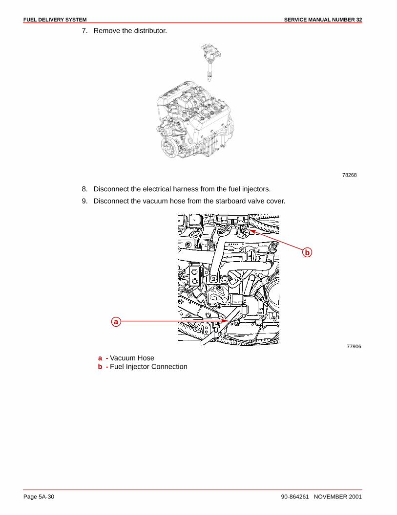
FUEL DELIVERY SYSTEM SERVICE MANUAL NUMBER 32
Page 5A-30 90-864261 NOVEMBER 2001
7. Remove the distributor.
78268
8. Disconnect the electrical harness from the fuel injectors.
9. Disconnect the vacuum hose from the starboard valve cover.
77906
a
b
a - Vacuum Hoseb - Fuel Injector Connection
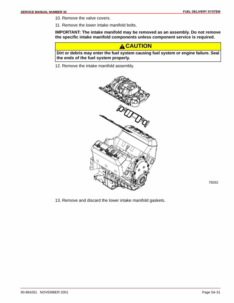
FUEL DELIVERY SYSTEMSERVICE MANUAL NUMBER 32
90-864261 NOVEMBER 2001 Page 5A-31
10. Remove the valve covers.
11. Remove the lower intake manifold bolts.
IMPORTANT: The intake manifold may be removed as an assembly. Do not removethe specific intake manifold components unless component service is required.
CAUTIONDirt or debris may enter the fuel system causing fuel system or engine failure. Sealthe ends of the fuel system properly.
12. Remove the intake manifold assembly.
78262
13. Remove and discard the lower intake manifold gaskets.
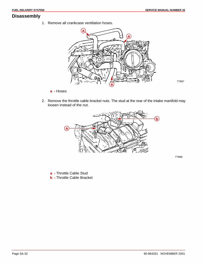
FUEL DELIVERY SYSTEM SERVICE MANUAL NUMBER 32
Page 5A-32 90-864261 NOVEMBER 2001
Disassembly1. Remove all crankcase ventilation hoses.
77997
aa
a
a - Hoses
2. Remove the throttle cable bracket nuts. The stud at the rear of the intake manifold mayloosen instead of the nut.
77998
a
b
a - Throttle Cable Studb - Throttle Cable Bracket
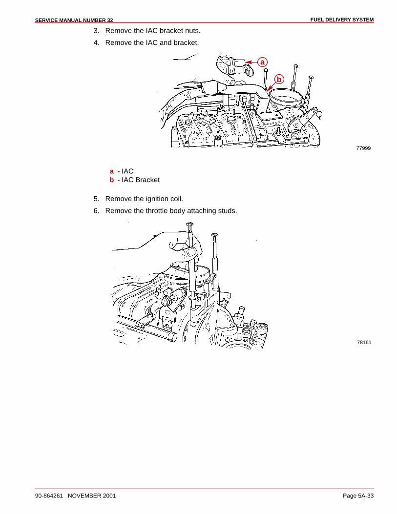
FUEL DELIVERY SYSTEMSERVICE MANUAL NUMBER 32
90-864261 NOVEMBER 2001 Page 5A-33
3. Remove the IAC bracket nuts.
4. Remove the IAC and bracket.
77999
a
b
a - IACb - IAC Bracket
5. Remove the ignition coil.
6. Remove the throttle body attaching studs.
78161
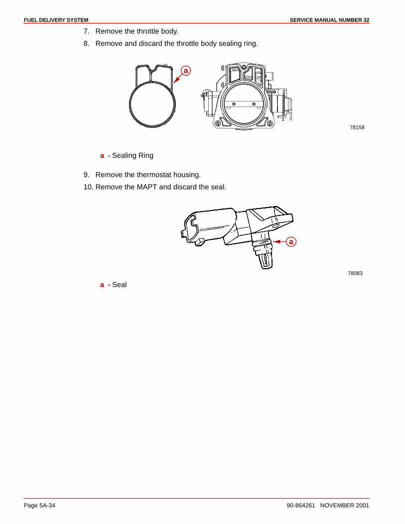
FUEL DELIVERY SYSTEM SERVICE MANUAL NUMBER 32
Page 5A-34 90-864261 NOVEMBER 2001
7. Remove the throttle body.
8. Remove and discard the throttle body sealing ring.
78158
a
a - Sealing Ring
9. Remove the thermostat housing.
10. Remove the MAPT and discard the seal.
78083
a
a - Seal
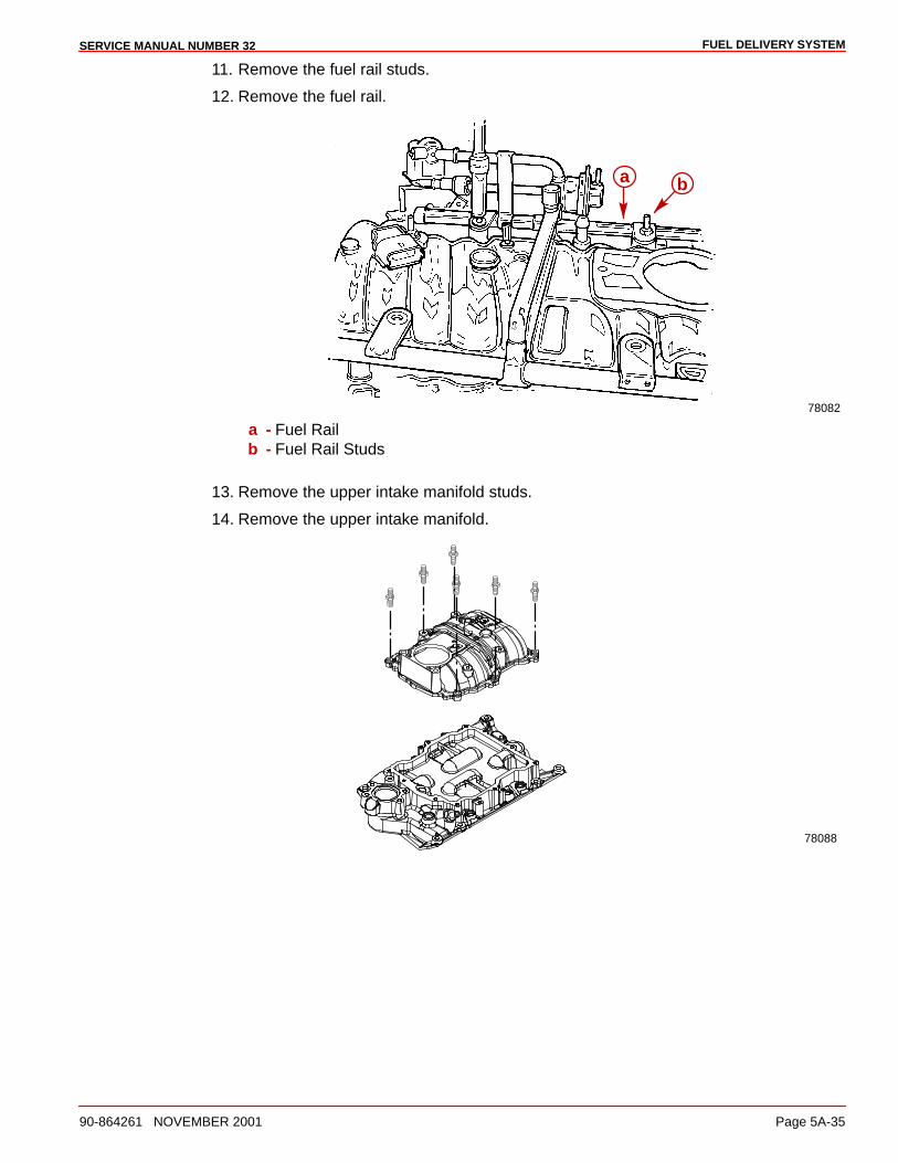
FUEL DELIVERY SYSTEMSERVICE MANUAL NUMBER 32
90-864261 NOVEMBER 2001 Page 5A-35
11. Remove the fuel rail studs.
12. Remove the fuel rail.
78082
a b
a - Fuel Railb - Fuel Rail Studs
13. Remove the upper intake manifold studs.
14. Remove the upper intake manifold.
78088
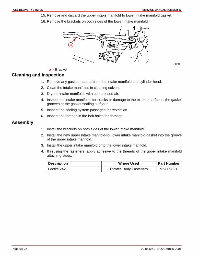
FUEL DELIVERY SYSTEM SERVICE MANUAL NUMBER 32
Page 5A-36 90-864261 NOVEMBER 2001
15. Remove and discard the upper intake manifold to lower intake manifold gasket.
16. Remove the brackets on both sides of the lower intake manifold.
78085
a
a - Bracket
Cleaning and Inspection1. Remove any gasket material from the intake manifold and cylinder head.
2. Clean the intake manifolds in cleaning solvent.
3. Dry the intake manifolds with compressed air.
4. Inspect the intake manifolds for cracks or damage to the exterior surfaces, the gasketgrooves or the gasket sealing surfaces.
5. Inspect the cooling system passages for restriction.
6. Inspect the threads in the bolt holes for damage.
Assembly1. Install the brackets on both sides of the lower intake manifold.
2. Install the new upper intake manifold-to- lower intake manifold gasket into the grooveof the upper intake manifold.
3. Install the upper intake manifold onto the lower intake manifold.
4. If reusing the fasteners, apply adhesive to the threads of the upper intake manifoldattaching studs.
Description Where Used Part Number
Loctite 242 Throttle Body Fasteners 92-809821
FUEL DELIVERY SYSTEMSERVICE MANUAL NUMBER 32
90-864261 NOVEMBER 2001 Page 5A-37
5. Install the upper intake manifold attaching studs.
6. Torque the upper intake manifold attaching studs.
Description Nm lb-in. lb-ft
Studs, Upper Intake Manifold
First Pass 5 44
SecondPass 10 89
7. Install the fuel rail and injectors on the intake manifold.
8. If reusing the fasteners, apply adhesive to the threads of the fuel rail bolt.
Description Where Used Part Number
Loctite 242 Throttle Body Fasteners 92-809821
9. Install the fuel rail studs.
10. Torque the fuel rail nuts.
Description Nm lb-in. lb-ft
Nuts, Fuel Rail Retainer 3 27
11. Install a new MAPT sensor seal onto the MAPT sensor.
12. Apply 1 drop of clean engine oil to the MAPT sensor seal.
13. Install the MAPT sensor into the upper intake manifold.
Description Nm lb-in. lb-ft
MAPT Fasteners 6 53
14. Install the ignition coil and the studs.
15. Torque the ignition coil studs.
Description Nm lb-in. lb-ft
Studs, Ignition Coil 12 106
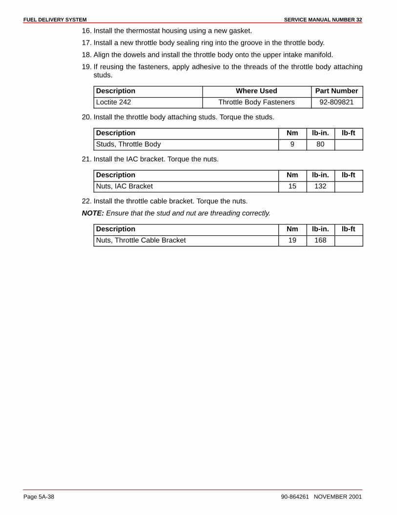
FUEL DELIVERY SYSTEM SERVICE MANUAL NUMBER 32
Page 5A-38 90-864261 NOVEMBER 2001
16. Install the thermostat housing using a new gasket.
17. Install a new throttle body sealing ring into the groove in the throttle body.
18. Align the dowels and install the throttle body onto the upper intake manifold.
19. If reusing the fasteners, apply adhesive to the threads of the throttle body attachingstuds.
Description Where Used Part Number
Loctite 242 Throttle Body Fasteners 92-809821
20. Install the throttle body attaching studs. Torque the studs.
Description Nm lb-in. lb-ft
Studs, Throttle Body 9 80
21. Install the IAC bracket. Torque the nuts.
Description Nm lb-in. lb-ft
Nuts, IAC Bracket 15 132
22. Install the throttle cable bracket. Torque the nuts.
NOTE: Ensure that the stud and nut are threading correctly.
Description Nm lb-in. lb-ft
Nuts, Throttle Cable Bracket 19 168
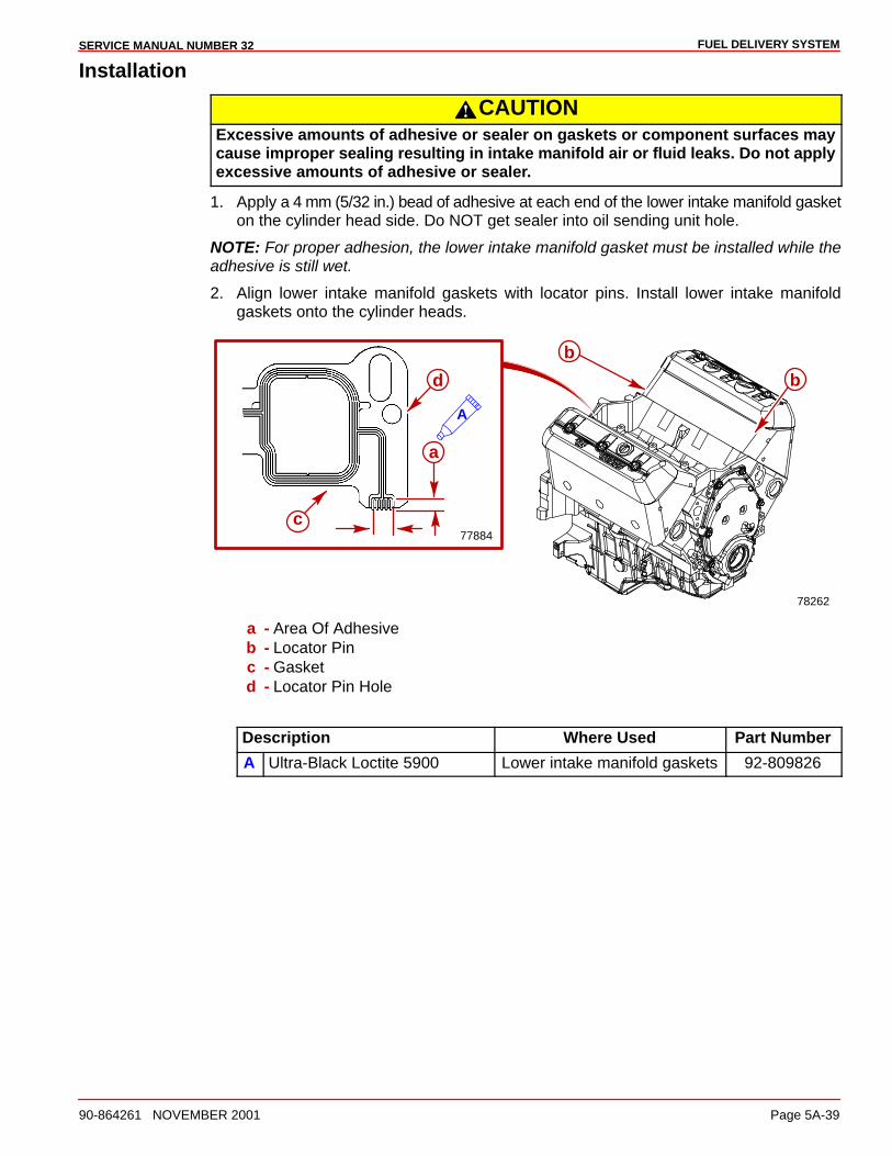
FUEL DELIVERY SYSTEMSERVICE MANUAL NUMBER 32
90-864261 NOVEMBER 2001 Page 5A-39
Installation
CAUTIONExcessive amounts of adhesive or sealer on gaskets or component surfaces maycause improper sealing resulting in intake manifold air or fluid leaks. Do not applyexcessive amounts of adhesive or sealer.
1. Apply a 4 mm (5/32 in.) bead of adhesive at each end of the lower intake manifold gasketon the cylinder head side. Do NOT get sealer into oil sending unit hole.
NOTE: For proper adhesion, the lower intake manifold gasket must be installed while theadhesive is still wet.
2. Align lower intake manifold gaskets with locator pins. Install lower intake manifoldgaskets onto the cylinder heads.
77884
a
b
b
c
d
78262
A
a - Area Of Adhesiveb - Locator Pinc - Gasketd - Locator Pin Hole
Description Where Used Part Number
A Ultra-Black Loctite 5900 Lower intake manifold gaskets 92-809826
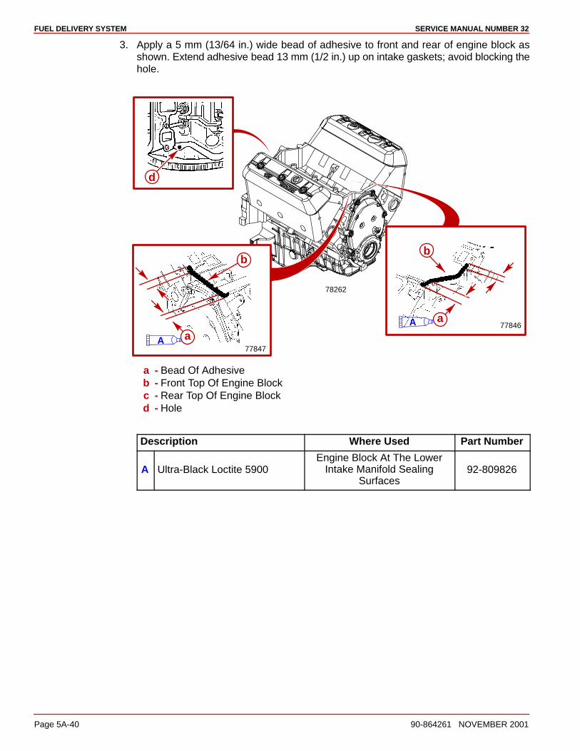
FUEL DELIVERY SYSTEM SERVICE MANUAL NUMBER 32
Page 5A-40 90-864261 NOVEMBER 2001
3. Apply a 5 mm (13/64 in.) wide bead of adhesive to front and rear of engine block asshown. Extend adhesive bead 13 mm (1/2 in.) up on intake gaskets; avoid blocking thehole.
78262
77847A
d
a
b
77846
b
aA
a - Bead Of Adhesiveb - Front Top Of Engine Blockc - Rear Top Of Engine Blockd - Hole
Description Where Used Part Number
A Ultra-Black Loctite 5900Engine Block At The Lower
Intake Manifold SealingSurfaces
92-809826

FUEL DELIVERY SYSTEMSERVICE MANUAL NUMBER 32
90-864261 NOVEMBER 2001 Page 5A-41
4. Coat threads of the lower intake manifold bolts with sealant.
5. Carefully install lower intake manifold, or intake manifold assembly, onto the engineblock.
CAUTIONAvoid engine damage. Crankshaft bearing bore alignment may become distortedresulting in damage to the crankshaft bearings if intake manifold fastener tighten-ing sequence and torque are done improperly. Always torque the bolts in sequenceto the specified amount in each of the three passes required.
6. Torque lower intake manifold bolts in sequence and passes indicated.
72878
1
2
3
4
5
6
7
8
FRONT
A a
78172
a - Intake Manifold Bolts
Description Where Used Part Number
A Loctite 242 Lower Intake Manifold Bolt 92-809821
Description Nm lb-in. lb-ft
Lower Intake Manifold Bolt (Each Pass In Sequence)
First Pass 3 27
Second Pass 12 106
Final Pass 15 132
FUEL DELIVERY SYSTEM SERVICE MANUAL NUMBER 32
Page 5A-42 90-864261 NOVEMBER 2001
7. Install the valve covers.
8. Connect all ignition and electrical leads.
9. Connect hoses to thermostat housing.
10. Install fuel line to fuel rail.
11. Connect crankcase ventilation hoses.
12. Install the distributor.
Description Nm lb-in. lb-ft
Distributor Hold Down Clamp Bolt 25 18
13. Install the ignition coil wire.
14. Install other ignition components and reconnect wires.
15. Connect any items that were disconnected.
16. Refill closed cooling system, if equipped.
CAUTIONOverheating caused by insufficient cooling water will result in engine and drive sys-tem damage. Ensure that there is sufficient water always available at water inletholes during operation.
17. Provide cooling water to the engine.
18. Start engine.
19. Check hose connections, gaskets and seals for leaks.
20. Inspect fuel line connections for fuel leaks.
21. Install the flame arrestor.
Description Nm lb-in. lb-ft
Nut, Flame Arrestor Retainer Bracket 12 108
22. Install engine cover.
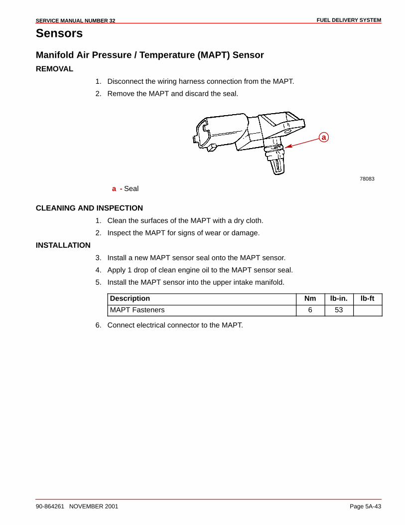
FUEL DELIVERY SYSTEMSERVICE MANUAL NUMBER 32
90-864261 NOVEMBER 2001 Page 5A-43
Sensors
Manifold Air Pressure / Temperature (MAPT) SensorREMOVAL
1. Disconnect the wiring harness connection from the MAPT.
2. Remove the MAPT and discard the seal.
78083
a
a - Seal
CLEANING AND INSPECTION
1. Clean the surfaces of the MAPT with a dry cloth.
2. Inspect the MAPT for signs of wear or damage.
INSTALLATION
3. Install a new MAPT sensor seal onto the MAPT sensor.
4. Apply 1 drop of clean engine oil to the MAPT sensor seal.
5. Install the MAPT sensor into the upper intake manifold.
Description Nm lb-in. lb-ft
MAPT Fasteners 6 53
6. Connect electrical connector to the MAPT.
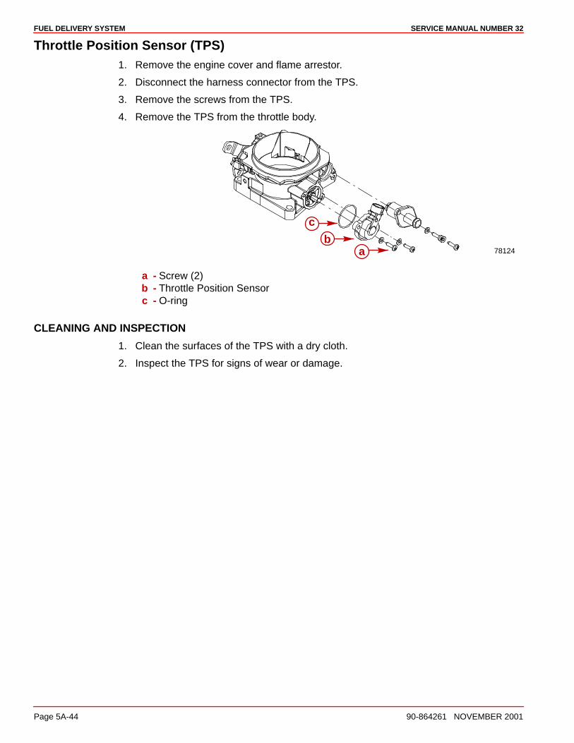
FUEL DELIVERY SYSTEM SERVICE MANUAL NUMBER 32
Page 5A-44 90-864261 NOVEMBER 2001
Throttle Position Sensor (TPS)1. Remove the engine cover and flame arrestor.
2. Disconnect the harness connector from the TPS.
3. Remove the screws from the TPS.
4. Remove the TPS from the throttle body.
78124a
c
b
a - Screw (2)b - Throttle Position Sensorc - O-ring
CLEANING AND INSPECTION
1. Clean the surfaces of the TPS with a dry cloth.
2. Inspect the TPS for signs of wear or damage.
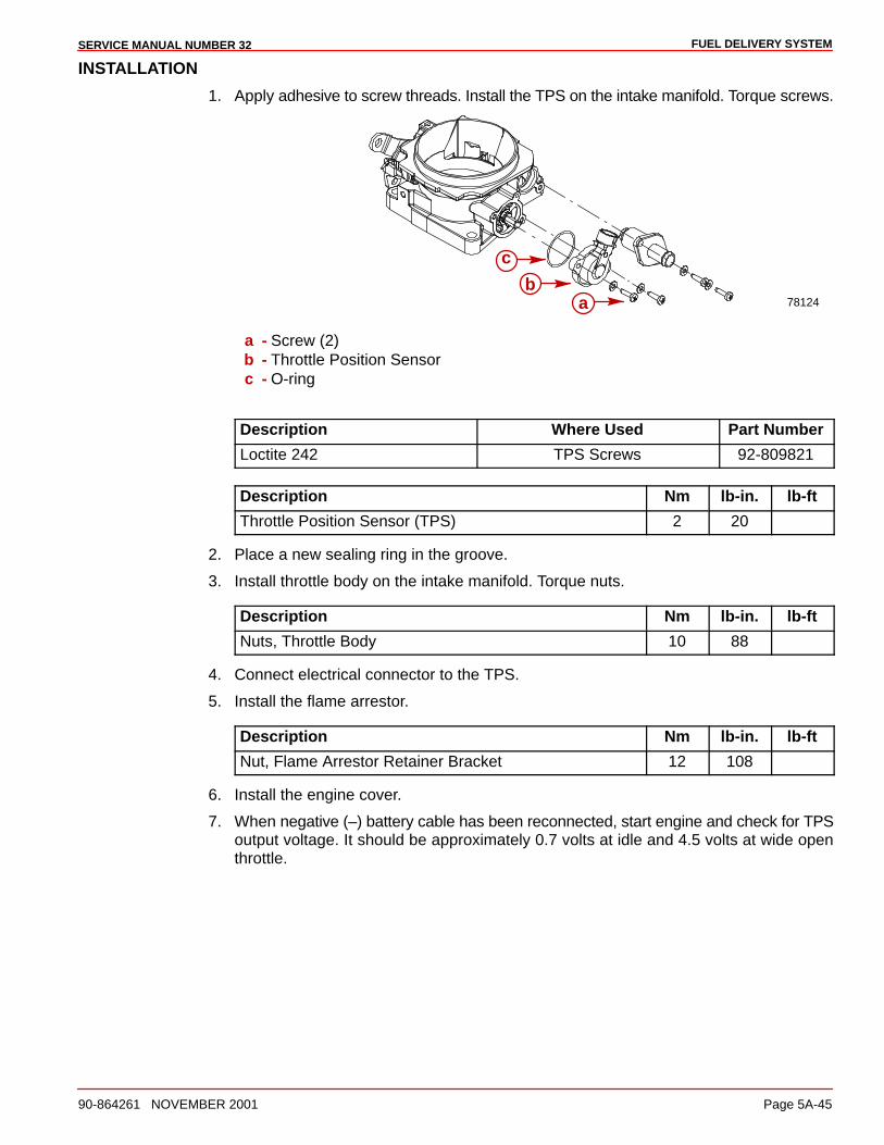
FUEL DELIVERY SYSTEMSERVICE MANUAL NUMBER 32
90-864261 NOVEMBER 2001 Page 5A-45
INSTALLATION
1. Apply adhesive to screw threads. Install the TPS on the intake manifold. Torque screws.
78124a
c
b
a - Screw (2)b - Throttle Position Sensorc - O-ring
Description Where Used Part Number
Loctite 242 TPS Screws 92-809821
Description Nm lb-in. lb-ft
Throttle Position Sensor (TPS) 2 20
2. Place a new sealing ring in the groove.
3. Install throttle body on the intake manifold. Torque nuts.
Description Nm lb-in. lb-ft
Nuts, Throttle Body 10 88
4. Connect electrical connector to the TPS.
5. Install the flame arrestor.
Description Nm lb-in. lb-ft
Nut, Flame Arrestor Retainer Bracket 12 108
6. Install the engine cover.
7. When negative (–) battery cable has been reconnected, start engine and check for TPSoutput voltage. It should be approximately 0.7 volts at idle and 4.5 volts at wide openthrottle.
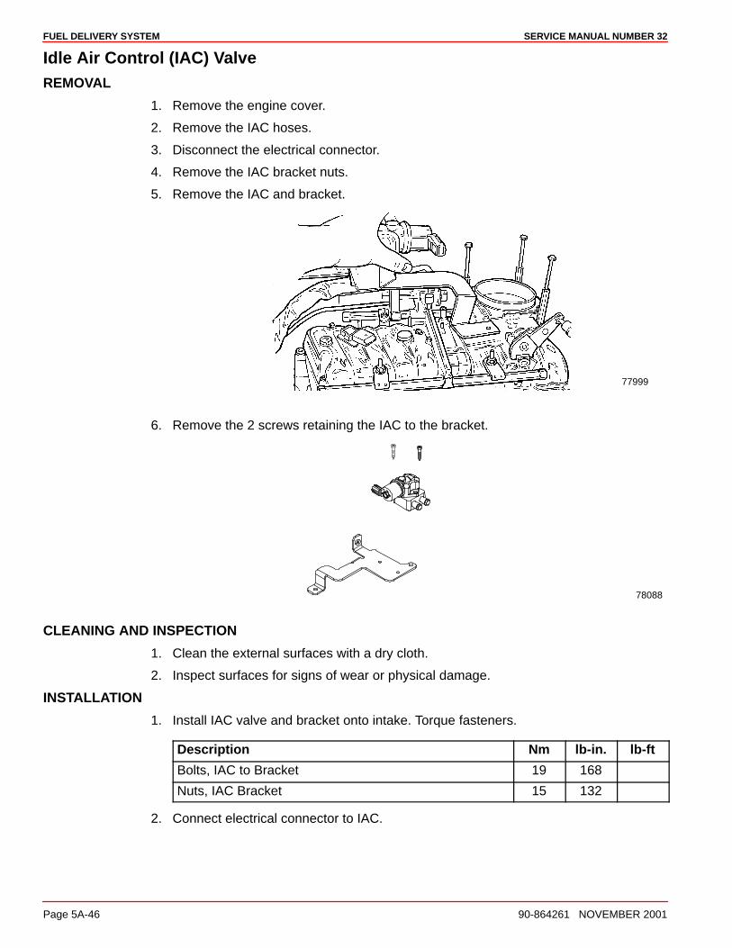
FUEL DELIVERY SYSTEM SERVICE MANUAL NUMBER 32
Page 5A-46 90-864261 NOVEMBER 2001
Idle Air Control (IAC) ValveREMOVAL
1. Remove the engine cover.
2. Remove the IAC hoses.
3. Disconnect the electrical connector.
4. Remove the IAC bracket nuts.
5. Remove the IAC and bracket.
77999
6. Remove the 2 screws retaining the IAC to the bracket.
78088
CLEANING AND INSPECTION
1. Clean the external surfaces with a dry cloth.
2. Inspect surfaces for signs of wear or physical damage.
INSTALLATION
1. Install IAC valve and bracket onto intake. Torque fasteners.
Description Nm lb-in. lb-ft
Bolts, IAC to Bracket 19 168
Nuts, IAC Bracket 15 132
2. Connect electrical connector to IAC.
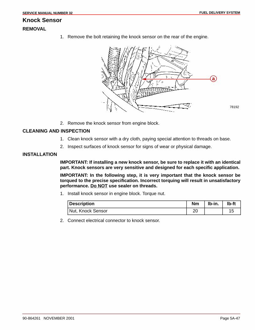
FUEL DELIVERY SYSTEMSERVICE MANUAL NUMBER 32
90-864261 NOVEMBER 2001 Page 5A-47
Knock SensorREMOVAL
1. Remove the bolt retaining the knock sensor on the rear of the engine.
78192
a
2. Remove the knock sensor from engine block.
CLEANING AND INSPECTION
1. Clean knock sensor with a dry cloth, paying special attention to threads on base.
2. Inspect surfaces of knock sensor for signs of wear or physical damage.
INSTALLATION
IMPORTANT: If installing a new knock sensor, be sure to replace it with an identicalpart. Knock sensors are very sensitive and designed for each specific application.
IMPORTANT: In the following step, it is very important that the knock sensor betorqued to the precise specification. Incorrect torquing will result in unsatisfactoryperformance. Do NOT use sealer on threads.
1. Install knock sensor in engine block. Torque nut.
Description Nm lb-in. lb-ft
Nut, Knock Sensor 20 15
2. Connect electrical connector to knock sensor.

FUEL DELIVERY SYSTEM SERVICE MANUAL NUMBER 32
Page 5A-48 90-864261 NOVEMBER 2001
Oil Pressure SensorREMOVAL
1. Disconnect the electrical connector.
78192
a
2. Remove the oil pressure sensor from the engine block.
CLEANING AND INSPECTION
1. Clean the external surfaces with a dry cloth.
2. Inspect surfaces for signs of wear or physical damage.
INSTALLATION
1. Install the sensor into the engine block.
Description Nm lb-in. lb-ft
Oil Pressure Sensor 20 15
2. Connect the electrical connector.
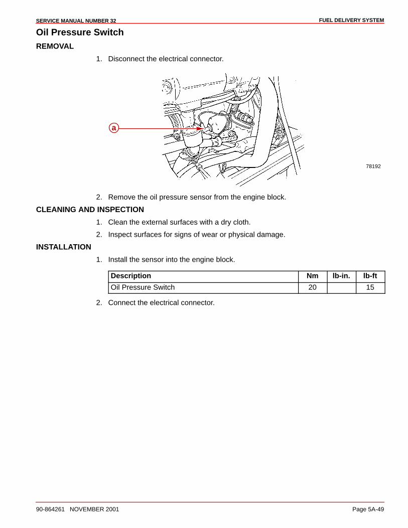
FUEL DELIVERY SYSTEMSERVICE MANUAL NUMBER 32
90-864261 NOVEMBER 2001 Page 5A-49
Oil Pressure SwitchREMOVAL
1. Disconnect the electrical connector.
78192
a
2. Remove the oil pressure sensor from the engine block.
CLEANING AND INSPECTION
1. Clean the external surfaces with a dry cloth.
2. Inspect surfaces for signs of wear or physical damage.
INSTALLATION
1. Install the sensor into the engine block.
Description Nm lb-in. lb-ft
Oil Pressure Switch 20 15
2. Connect the electrical connector.
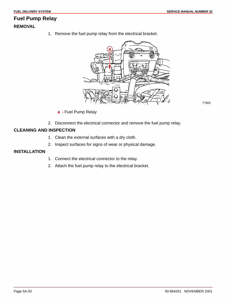
FUEL DELIVERY SYSTEM SERVICE MANUAL NUMBER 32
Page 5A-50 90-864261 NOVEMBER 2001
Fuel Pump RelayREMOVAL
1. Remove the fuel pump relay from the electrical bracket.
77905
a
a - Fuel Pump Relay
2. Disconnect the electrical connector and remove the fuel pump relay.
CLEANING AND INSPECTION
1. Clean the external surfaces with a dry cloth.
2. Inspect surfaces for signs of wear or physical damage.
INSTALLATION
1. Connect the electrical connector to the relay.
2. Attach the fuel pump relay to the electrical bracket.
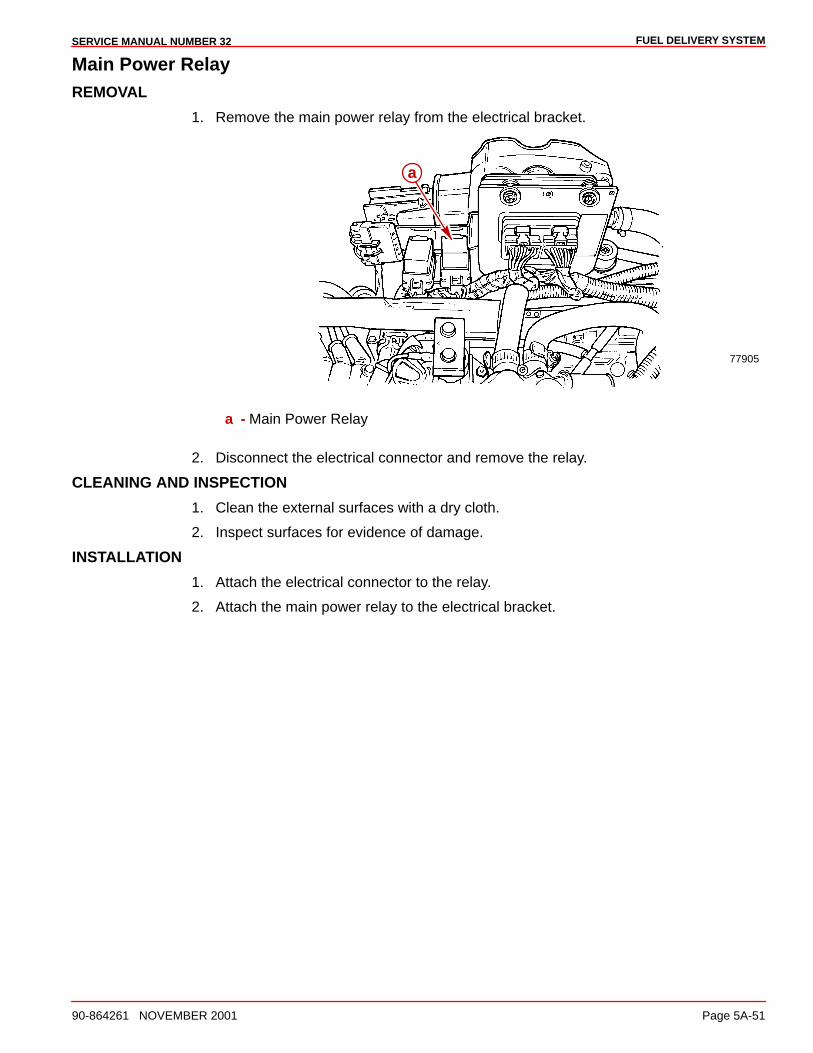
FUEL DELIVERY SYSTEMSERVICE MANUAL NUMBER 32
90-864261 NOVEMBER 2001 Page 5A-51
Main Power RelayREMOVAL
1. Remove the main power relay from the electrical bracket.
77905
a
a - Main Power Relay
2. Disconnect the electrical connector and remove the relay.
CLEANING AND INSPECTION
1. Clean the external surfaces with a dry cloth.
2. Inspect surfaces for evidence of damage.
INSTALLATION
1. Attach the electrical connector to the relay.
2. Attach the main power relay to the electrical bracket.
6A
ALL MODELSSERVICE MANUAL NUMBER 32
90-864261 NOVEMBER 2001 Page 6A-1
COOLING SYSTEMSection 6A - All Models
Table of Contents
Torque Specifications 6A-2. . . . . . . . . . . . . . . . Lubricants / Sealants / Adhesives 6A-2. . . . . Seawater Inlet Recommendations 6A-3. . . . .
Seacock (Seawater Inlet Valve) 6A-3. . . . . Seawater Strainer 6A-3. . . . . . . . . . . . . . . .
Seawater Pickups 6A-4. . . . . . . . . . . . . . . . . . . Through the Hull Mounted 6A-4. . . . . . . . . Transom Mounted 6A-6. . . . . . . . . . . . . . . .
Quicksilver Sea Strainer 6A-8. . . . . . . . . . . . . . Removal 6A-8. . . . . . . . . . . . . . . . . . . . . . . . Cleaning and Inspection 6A-9. . . . . . . . . . . Installation 6A-10. . . . . . . . . . . . . . . . . . . . . . .
Auxiliary Hot Water Heater Installation 6A-11. Supply Hose Connection 6A-11. . . . . . . . . . Return Hose Connection 6A-12. . . . . . . . . .
Seawater Pump 6A-12. . . . . . . . . . . . . . . . . . . . . Output Test 6A-12. . . . . . . . . . . . . . . . . . . . . . Removal 6A-14. . . . . . . . . . . . . . . . . . . . . . . . Disassembly 6A-15. . . . . . . . . . . . . . . . . . . . . Cleaning and Inspection 6A-16. . . . . . . . . . . Reassembly 6A-16. . . . . . . . . . . . . . . . . . . . . Installation 6A-19. . . . . . . . . . . . . . . . . . . . . . .
Water Circulating Pump 6A-20. . . . . . . . . . . . . . Removal 6A-20. . . . . . . . . . . . . . . . . . . . . . . . Cleaning and Inspection 6A-21. . . . . . . . . . . Installation 6A-22. . . . . . . . . . . . . . . . . . . . . . .
Water Distribution Housing 6A-23. . . . . . . . . . . Removal 6A-23. . . . . . . . . . . . . . . . . . . . . . . . Cleaning And Inspection 6A-23. . . . . . . . . . . Installation 6A-23. . . . . . . . . . . . . . . . . . . . . . .
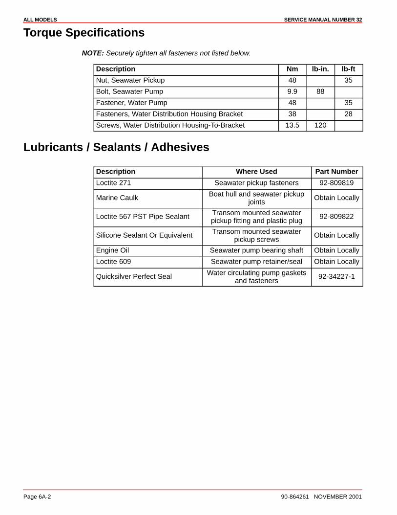
ALL MODELS SERVICE MANUAL NUMBER 32
Page 6A-2 90-864261 NOVEMBER 2001
Torque Specifications
NOTE: Securely tighten all fasteners not listed below.
Description Nm lb-in. lb-ft
Nut, Seawater Pickup 48 35
Bolt, Seawater Pump 9.9 88
Fastener, Water Pump 48 35
Fasteners, Water Distribution Housing Bracket 38 28
Screws, Water Distribution Housing-To-Bracket 13.5 120
Lubricants / Sealants / Adhesives
Description Where Used Part Number
Loctite 271 Seawater pickup fasteners 92-809819
Marine Caulk Boat hull and seawater pickupjoints
Obtain Locally
Loctite 567 PST Pipe Sealant Transom mounted seawaterpickup fitting and plastic plug
92-809822
Silicone Sealant Or Equivalent Transom mounted seawaterpickup screws
Obtain Locally
Engine Oil Seawater pump bearing shaft Obtain Locally
Loctite 609 Seawater pump retainer/seal Obtain Locally
Quicksilver Perfect Seal Water circulating pump gasketsand fasteners
92-34227-1
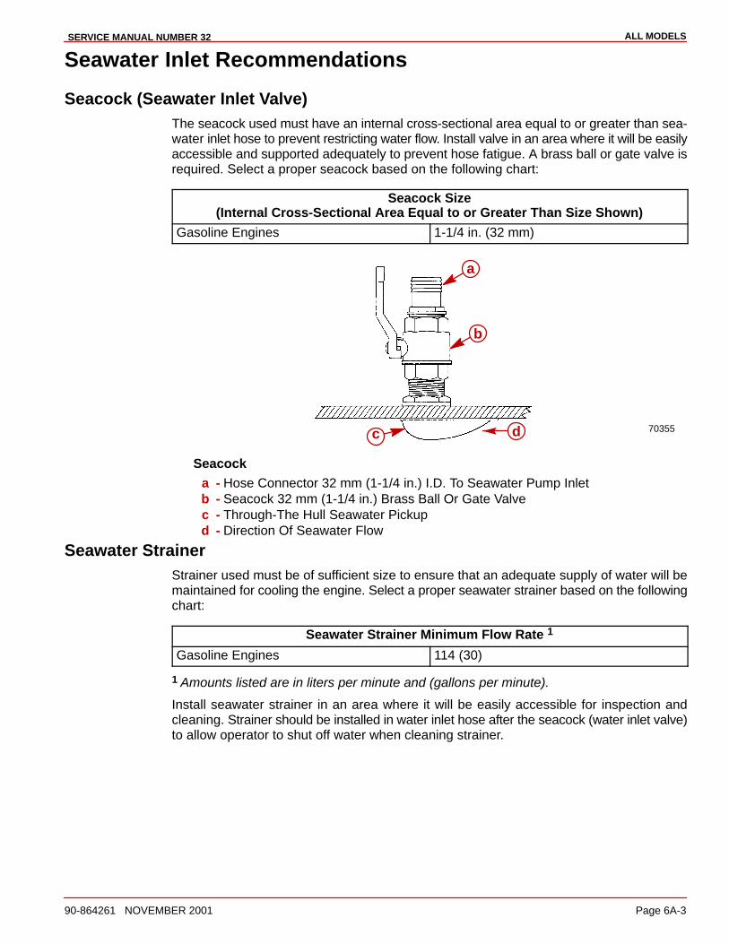
ALL MODELSSERVICE MANUAL NUMBER 32
90-864261 NOVEMBER 2001 Page 6A-3
Seawater Inlet Recommendations
Seacock (Seawater Inlet Valve)The seacock used must have an internal cross-sectional area equal to or greater than sea-water inlet hose to prevent restricting water flow. Install valve in an area where it will be easilyaccessible and supported adequately to prevent hose fatigue. A brass ball or gate valve isrequired. Select a proper seacock based on the following chart:
Seacock Size(Internal Cross-Sectional Area Equal to or Greater Than Size Shown)
Gasoline Engines 1-1/4 in. (32 mm)
70355
a
b
c d
Seacocka - Hose Connector 32 mm (1-1/4 in.) I.D. To Seawater Pump Inletb - Seacock 32 mm (1-1/4 in.) Brass Ball Or Gate Valvec - Through-The Hull Seawater Pickupd - Direction Of Seawater Flow
Seawater StrainerStrainer used must be of sufficient size to ensure that an adequate supply of water will bemaintained for cooling the engine. Select a proper seawater strainer based on the followingchart:
Seawater Strainer Minimum Flow Rate 1
Gasoline Engines 114 (30)
1 Amounts listed are in liters per minute and (gallons per minute).
Install seawater strainer in an area where it will be easily accessible for inspection andcleaning. Strainer should be installed in water inlet hose after the seacock (water inlet valve)to allow operator to shut off water when cleaning strainer.

ALL MODELS SERVICE MANUAL NUMBER 32
Page 6A-4 90-864261 NOVEMBER 2001
Seawater Pickups
NOTICE
Refer to the manufacturer’s instructions for information on removal and installationof other than Quicksilver Seawater Pickups.
IMPORTANT: Seal the inside edges of any hole made through the hull with a suitablesealant to prevent water absorption and deterioration.
Through the Hull Mounted
72639a
b
c
d
a - Seawater Pickupb - Seawater Inlet Slotsc - Mounting Screw Holesd - Nut
1. Seal the inside edges of the 44 mm (1-3/4 in.) hole in the hull using a suitable sealer.
2. Apply marine caulking (sealer) to the mounting surface on the seawater pickup wherethe hull contact will occur when installed.

ALL MODELSSERVICE MANUAL NUMBER 32
90-864261 NOVEMBER 2001 Page 6A-5
IMPORTANT: The seawater inlet slots must face forward - parallel with the flow ofwater.
3. Ensure that the slots in the seawater pickup are facing forward (toward the bow of theboat) and install the seawater pickup through the hull.
4. Fasten the pickup with mounting screws.
5. Apply sealant as needed inside the boat. Apply adhesive to the threads of the nut.
6. Install on the pickup and torque.
7. Ensure that the seawater inlet holes face forward.
Description Where Used Part Number
Loctite 271 Seawater pickup fasteners 92-809819
Marine Caulk Boat hull and seawater pickupjoints
Obtain Locally
Description Nm lb-in. lb-ft
Nut, Seawater Pickup 48 35
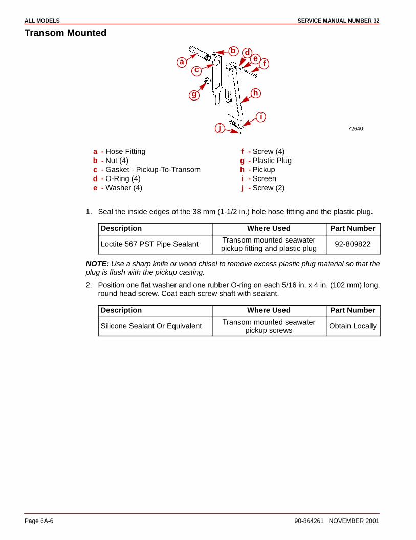
ALL MODELS SERVICE MANUAL NUMBER 32
Page 6A-6 90-864261 NOVEMBER 2001
Transom Mounted
72640
b de
f
g h
ij
ac
a - Hose Fittingb - Nut (4)c - Gasket - Pickup-To-Transomd - O-Ring (4)e - Washer (4)
f - Screw (4)g - Plastic Plugh - Pickupi - Screenj - Screw (2)
1. Seal the inside edges of the 38 mm (1-1/2 in.) hole hose fitting and the plastic plug.
Description Where Used Part Number
Loctite 567 PST Pipe Sealant Transom mounted seawaterpickup fitting and plastic plug
92-809822
NOTE: Use a sharp knife or wood chisel to remove excess plastic plug material so that theplug is flush with the pickup casting.
2. Position one flat washer and one rubber O-ring on each 5/16 in. x 4 in. (102 mm) long,round head screw. Coat each screw shaft with sealant.
Description Where Used Part Number
Silicone Sealant Or Equivalent Transom mounted seawaterpickup screws
Obtain Locally
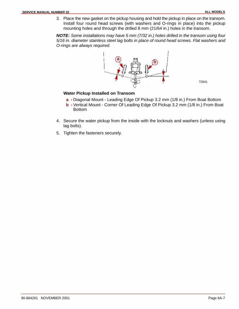
ALL MODELSSERVICE MANUAL NUMBER 32
90-864261 NOVEMBER 2001 Page 6A-7
3. Place the new gasket on the pickup housing and hold the pickup in place on the transom.Install four round head screws (with washers and O-rings in place) into the pickupmounting holes and through the drilled 8 mm (21/64 in.) holes in the transom.
NOTE: Some installations may have 5 mm (7/32 in.) holes drilled in the transom using four5/16 in. diameter stainless steel lag bolts in place of round head screws. Flat washers andO-rings are always required.
72641
ab
Water Pickup Installed on Transoma - Diagonal Mount - Leading Edge Of Pickup 3.2 mm (1/8 in.) From Boat Bottomb - Vertical Mount - Corner Of Leading Edge Of Pickup 3.2 mm (1/8 in.) From Boat
Bottom
4. Secure the water pickup from the inside with the locknuts and washers (unless usinglag bolts).
5. Tighten the fasteners securely.
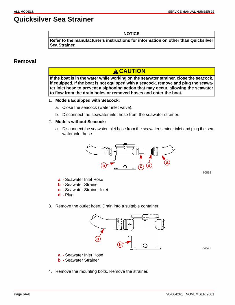
ALL MODELS SERVICE MANUAL NUMBER 32
Page 6A-8 90-864261 NOVEMBER 2001
Quicksilver Sea Strainer
NOTICE
Refer to the manufacturer’s instructions for information on other than QuicksilverSea Strainer.
Removal
CAUTIONIf the boat is in the water while working on the seawater strainer, close the seacock,if equipped. If the boat is not equipped with a seacock, remove and plug the seawa-ter inlet hose to prevent a siphoning action that may occur, allowing the seawaterto flow from the drain holes or removed hoses and enter the boat.
1. Models Equipped with Seacock:
a. Close the seacock (water inlet valve).
b. Disconnect the seawater inlet hose from the seawater strainer.
2. Models without Seacock:
a. Disconnect the seawater inlet hose from the seawater strainer inlet and plug the sea-water inlet hose.
70062
ab c d
a - Seawater Inlet Hoseb - Seawater Strainerc - Seawater Strainer Inletd - Plug
3. Remove the outlet hose. Drain into a suitable container.
72643
ab
a - Seawater Inlet Hoseb - Seawater Strainer
4. Remove the mounting bolts. Remove the strainer.
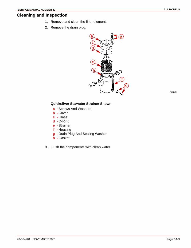
ALL MODELSSERVICE MANUAL NUMBER 32
90-864261 NOVEMBER 2001 Page 6A-9
Cleaning and Inspection1. Remove and clean the filter element.
2. Remove the drain plug.
72673
ab
c
d
e
f
g
h
Quicksilver Seawater Strainer Showna - Screws And Washersb - Coverc - Glassd - O-Ringe - Strainerf - Housingg - Drain Plug And Sealing Washerh - Gasket
3. Flush the components with clean water.

ALL MODELS SERVICE MANUAL NUMBER 32
Page 6A-10 90-864261 NOVEMBER 2001
InstallationIMPORTANT: Mount the seawater strainer in a vibration-free location. Never mountit on the engine or the transmission. Hoses must not be kinked or allowed to comein contact with hot or moving engine or transmission parts.
1. Mount the seawater strainer. The arrow indicates the required water flow direction andmust point toward the seawater pump. Tighten the mounting bolts securely.
72644
b
c c
a
a - Seawater Strainerb - Arrowc - Mounting Bolt Hole Location (Bolts Not Shown)
2. Remove the plug from the seawater inlet hose (if installed previously) and install thehose on the strainer. Install the seawater outlet hose. Use two hose clamps on eachhose connection. Tighten the clamps securely.
72645
a
bcc
a - Seawater Inlet Hoseb - Seawater Outlet Hosec - Double Hose Clamps
3. Check the drain plug and the lens cover bolts. Tighten securely. Do not overtighten thecover bolts or the cover may warp and leak water into the boat.
72644
a
b
a - Drain Plugb - Lens Cover Bolts (2, One Not Shown In This View)
4. Open the seacock, if equipped.
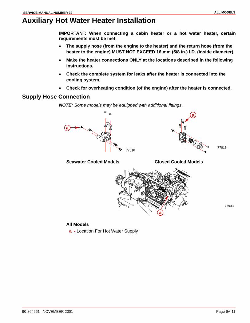
ALL MODELSSERVICE MANUAL NUMBER 32
90-864261 NOVEMBER 2001 Page 6A-11
Auxiliary Hot Water Heater Installation
IMPORTANT: When connecting a cabin heater or a hot water heater, certainrequirements must be met:
• The supply hose (from the engine to the heater) and the return hose (from theheater to the engine) MUST NOT EXCEED 16 mm (5/8 in.) I.D. (inside diameter).
• Make the heater connections ONLY at the locations described in the followinginstructions.
• Check the complete system for leaks after the heater is connected into thecooling system.
• Check for overheating condition (of the engine) after the heater is connected.
Supply Hose ConnectionNOTE: Some models may be equipped with additional fittings.
7781677815
a
a
Seawater Cooled Models Closed Cooled Models
77933
a
All Modelsa - Location For Hot Water Supply
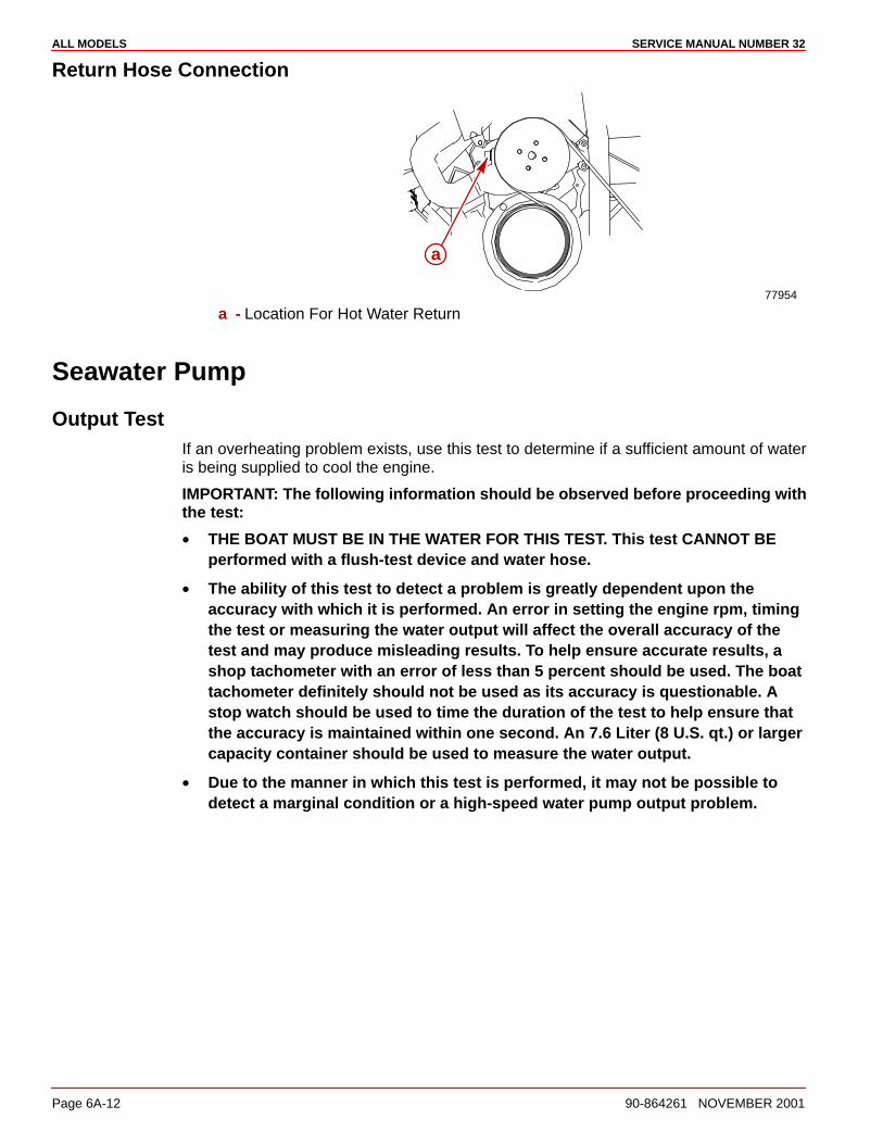
ALL MODELS SERVICE MANUAL NUMBER 32
Page 6A-12 90-864261 NOVEMBER 2001
Return Hose Connection
77954
a
a - Location For Hot Water Return
Seawater Pump
Output TestIf an overheating problem exists, use this test to determine if a sufficient amount of wateris being supplied to cool the engine.
IMPORTANT: The following information should be observed before proceeding withthe test:
• THE BOAT MUST BE IN THE WATER FOR THIS TEST. This test CANNOT BEperformed with a flush-test device and water hose.
• The ability of this test to detect a problem is greatly dependent upon theaccuracy with which it is performed. An error in setting the engine rpm, timingthe test or measuring the water output will affect the overall accuracy of thetest and may produce misleading results. To help ensure accurate results, ashop tachometer with an error of less than 5 percent should be used. The boattachometer definitely should not be used as its accuracy is questionable. Astop watch should be used to time the duration of the test to help ensure thatthe accuracy is maintained within one second. An 7.6 Liter (8 U.S. qt.) or largercapacity container should be used to measure the water output.
• Due to the manner in which this test is performed, it may not be possible todetect a marginal condition or a high-speed water pump output problem.
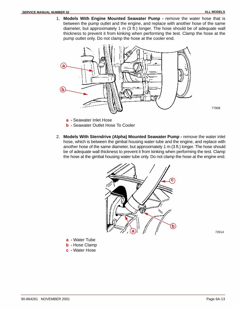
ALL MODELSSERVICE MANUAL NUMBER 32
90-864261 NOVEMBER 2001 Page 6A-13
1. Models With Engine Mounted Seawater Pump - remove the water hose that isbetween the pump outlet and the engine, and replace with another hose of the samediameter, but approximately 1 m (3 ft.) longer. The hose should be of adequate wallthickness to prevent it from kinking when performing the test. Clamp the hose at thepump outlet only. Do not clamp the hose at the cooler end.
77908
a
b
a - Seawater Inlet Hoseb - Seawater Outlet Hose To Cooler
2. Models With Sterndrive (Alpha) Mounted Seawater Pump - remove the water inlethose, which is between the gimbal housing water tube and the engine, and replace withanother hose of the same diameter, but approximately 1 m (3 ft.) longer. The hose shouldbe of adequate wall thickness to prevent it from kinking when performing the test. Clampthe hose at the gimbal housing water tube only. Do not clamp the hose at the engine end.
72614
ba
c
a - Water Tubeb - Hose Clampc - Water Hose
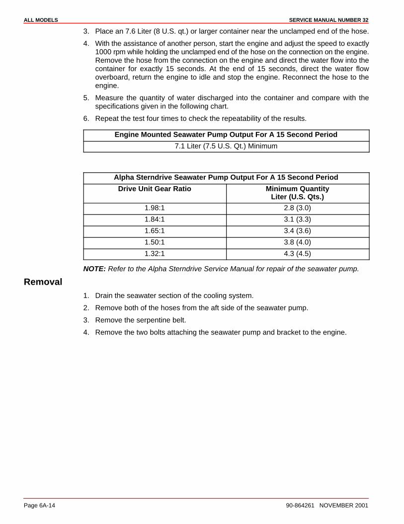
ALL MODELS SERVICE MANUAL NUMBER 32
Page 6A-14 90-864261 NOVEMBER 2001
3. Place an 7.6 Liter (8 U.S. qt.) or larger container near the unclamped end of the hose.
4. With the assistance of another person, start the engine and adjust the speed to exactly1000 rpm while holding the unclamped end of the hose on the connection on the engine.Remove the hose from the connection on the engine and direct the water flow into thecontainer for exactly 15 seconds. At the end of 15 seconds, direct the water flowoverboard, return the engine to idle and stop the engine. Reconnect the hose to theengine.
5. Measure the quantity of water discharged into the container and compare with thespecifications given in the following chart.
6. Repeat the test four times to check the repeatability of the results.
Engine Mounted Seawater Pump Output For A 15 Second Period
7.1 Liter (7.5 U.S. Qt.) Minimum
Alpha Sterndrive Seawater Pump Output For A 15 Second Period
Drive Unit Gear Ratio Minimum QuantityLiter (U.S. Qts.)
1.98:1 2.8 (3.0)
1.84:1 3.1 (3.3)
1.65:1 3.4 (3.6)
1.50:1 3.8 (4.0)
1.32:1 4.3 (4.5)
NOTE: Refer to the Alpha Sterndrive Service Manual for repair of the seawater pump.
Removal1. Drain the seawater section of the cooling system.
2. Remove both of the hoses from the aft side of the seawater pump.
3. Remove the serpentine belt.
4. Remove the two bolts attaching the seawater pump and bracket to the engine.

ALL MODELSSERVICE MANUAL NUMBER 32
90-864261 NOVEMBER 2001 Page 6A-15
Disassembly1. Press off the pulley.
2. Remove the six bolts from the rear of the seawater pump.
3. Remove and discard the O-ring.
4. Remove the impeller.
5. Remove the retainer/seal from the front of the seawater pump.
6. Remove the retainer ring.
7. From the impeller side, press the bearing shaft out of the housing.
8. Remove the rear oil seal from the housing.
78136
a
b
c
d
e
f
g
h
i
a - Seawater Pump Backplateb - O-ringc - Impellerd - Seawater Pump Bearing Housinge - Rear Oil Sealf - Bearing Shaft Assemblyg - Tolerance Ringh - Retainer/Seali - Pulley
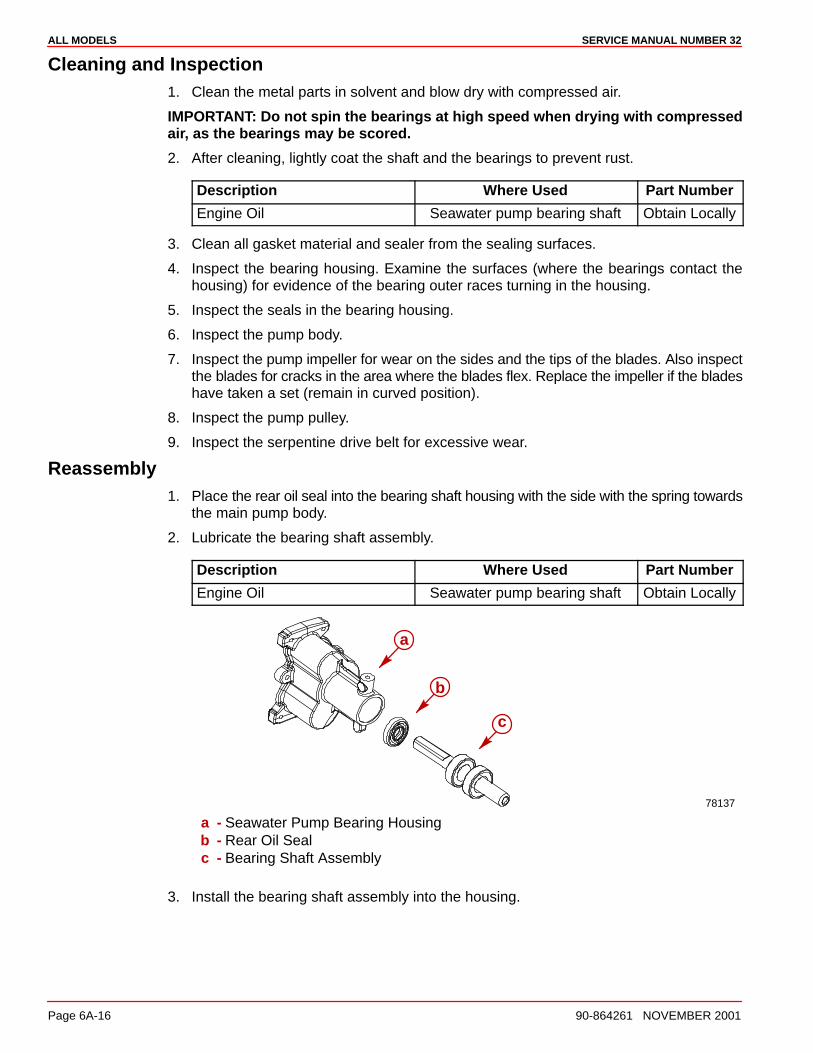
ALL MODELS SERVICE MANUAL NUMBER 32
Page 6A-16 90-864261 NOVEMBER 2001
Cleaning and Inspection1. Clean the metal parts in solvent and blow dry with compressed air.
IMPORTANT: Do not spin the bearings at high speed when drying with compressedair, as the bearings may be scored.
2. After cleaning, lightly coat the shaft and the bearings to prevent rust.
Description Where Used Part Number
Engine Oil Seawater pump bearing shaft Obtain Locally
3. Clean all gasket material and sealer from the sealing surfaces.
4. Inspect the bearing housing. Examine the surfaces (where the bearings contact thehousing) for evidence of the bearing outer races turning in the housing.
5. Inspect the seals in the bearing housing.
6. Inspect the pump body.
7. Inspect the pump impeller for wear on the sides and the tips of the blades. Also inspectthe blades for cracks in the area where the blades flex. Replace the impeller if the bladeshave taken a set (remain in curved position).
8. Inspect the pump pulley.
9. Inspect the serpentine drive belt for excessive wear.
Reassembly1. Place the rear oil seal into the bearing shaft housing with the side with the spring towards
the main pump body.
2. Lubricate the bearing shaft assembly.
Description Where Used Part Number
Engine Oil Seawater pump bearing shaft Obtain Locally
78137
a
c
b
a - Seawater Pump Bearing Housingb - Rear Oil Sealc - Bearing Shaft Assembly
3. Install the bearing shaft assembly into the housing.
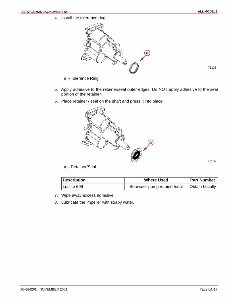
ALL MODELSSERVICE MANUAL NUMBER 32
90-864261 NOVEMBER 2001 Page 6A-17
4. Install the tolerance ring.
78138
a
a - Tolerance Ring
5. Apply adhesive to the retainer/seal outer edges. Do NOT apply adhesive to the sealportion of the retainer.
6. Place retainer / seal on the shaft and press it into place.
78139
a
a - Retainer/Seal
Description Where Used Part Number
Loctite 609 Seawater pump retainer/seal Obtain Locally
7. Wipe away excess adhesive.
8. Lubricate the impeller with soapy water.
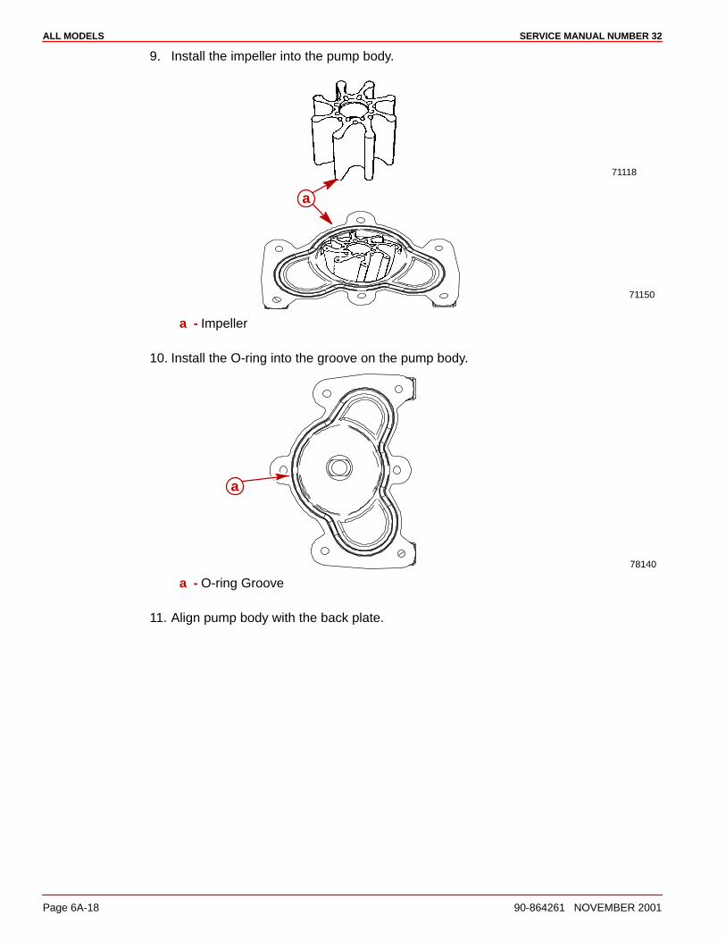
ALL MODELS SERVICE MANUAL NUMBER 32
Page 6A-18 90-864261 NOVEMBER 2001
9. Install the impeller into the pump body.
71118
71150
a
a - Impeller
10. Install the O-ring into the groove on the pump body.
78140
a
a - O-ring Groove
11. Align pump body with the back plate.
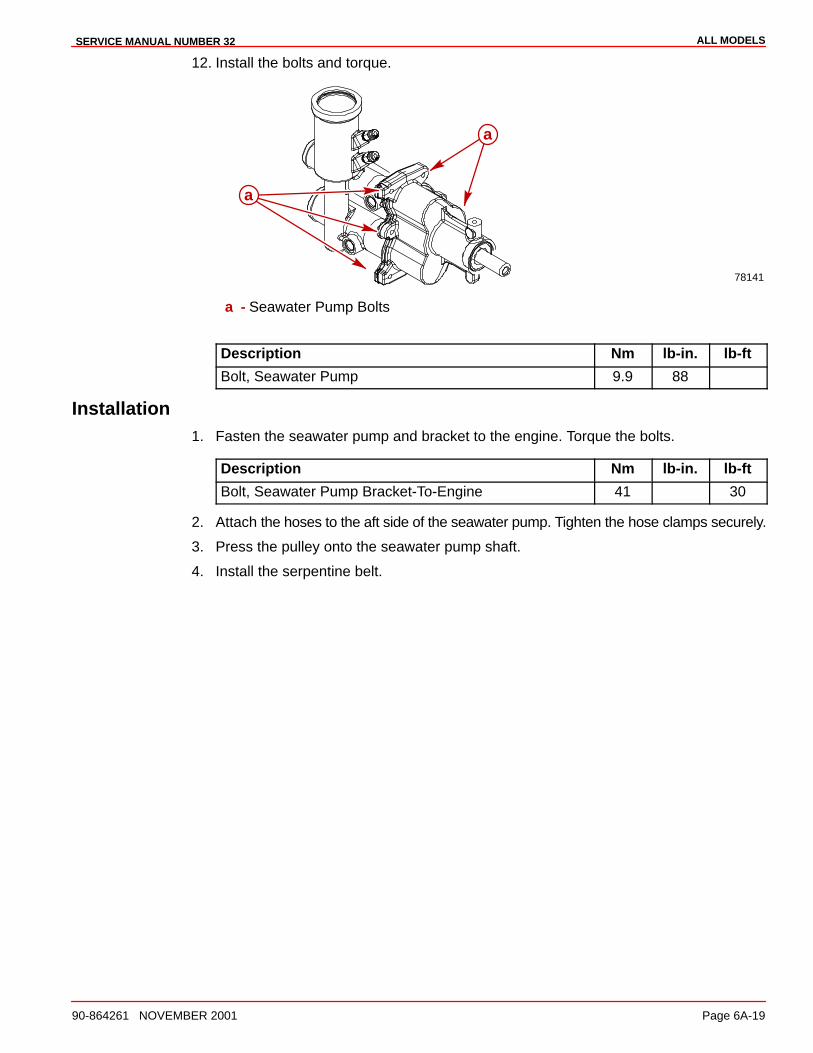
ALL MODELSSERVICE MANUAL NUMBER 32
90-864261 NOVEMBER 2001 Page 6A-19
12. Install the bolts and torque.
78141
a
a
a - Seawater Pump Bolts
Description Nm lb-in. lb-ft
Bolt, Seawater Pump 9.9 88
Installation1. Fasten the seawater pump and bracket to the engine. Torque the bolts.
Description Nm lb-in. lb-ft
Bolt, Seawater Pump Bracket-To-Engine 41 30
2. Attach the hoses to the aft side of the seawater pump. Tighten the hose clamps securely.
3. Press the pulley onto the seawater pump shaft.
4. Install the serpentine belt.

ALL MODELS SERVICE MANUAL NUMBER 32
Page 6A-20 90-864261 NOVEMBER 2001
Water Circulating Pump
Removal1. Allow engine to cool.
2. Drain the seawater and closed cooling (if equipped) sections of the engine.
3. Remove serpentine belt.
4. Remove the hoses attached to the water circulating pump.
5. Remove bolts and water pump pulley.
77954
a
a - Water Circulating Pump Pulley
6. Remove the fasteners and the water circulating pump.
a
b
a - Water Circulating Pumpb - Fasteners
7. Remove and discard the old gaskets.
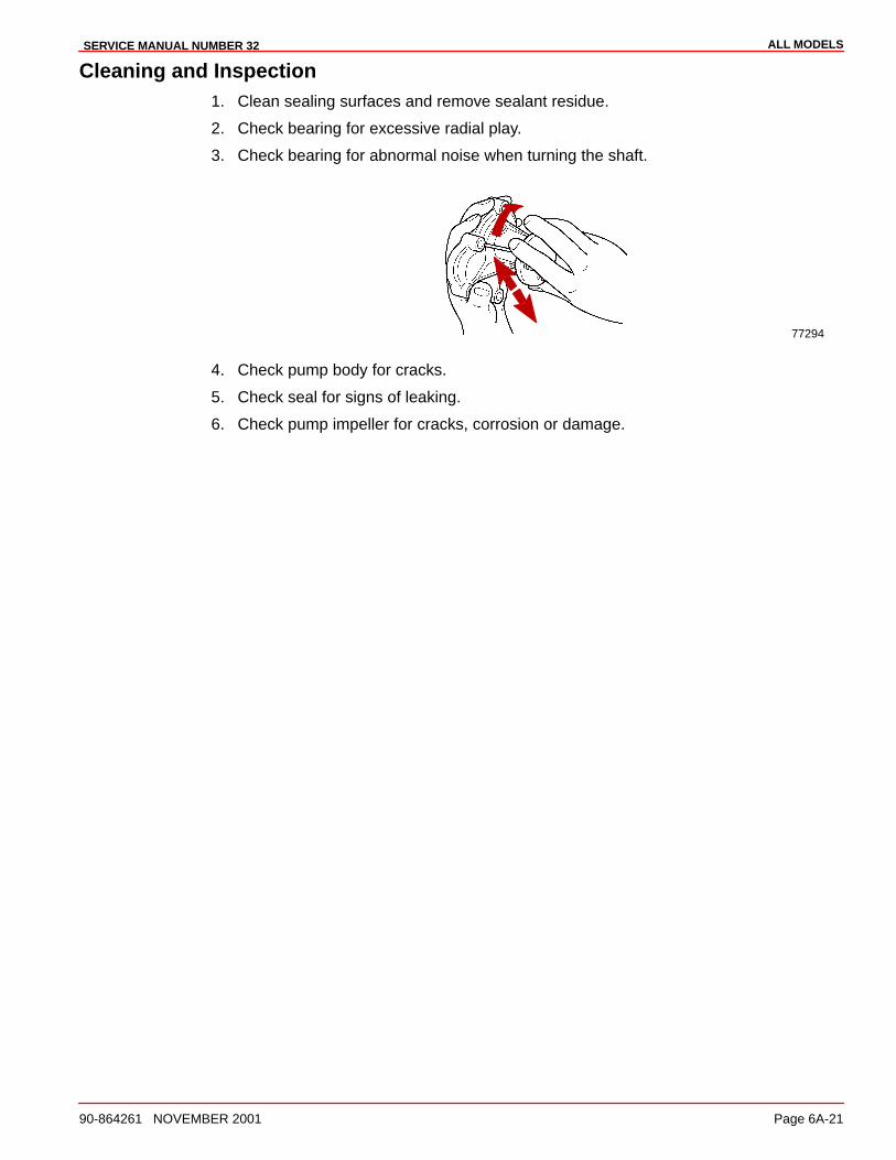
ALL MODELSSERVICE MANUAL NUMBER 32
90-864261 NOVEMBER 2001 Page 6A-21
Cleaning and Inspection1. Clean sealing surfaces and remove sealant residue.
2. Check bearing for excessive radial play.
3. Check bearing for abnormal noise when turning the shaft.
77294
4. Check pump body for cracks.
5. Check seal for signs of leaking.
6. Check pump impeller for cracks, corrosion or damage.
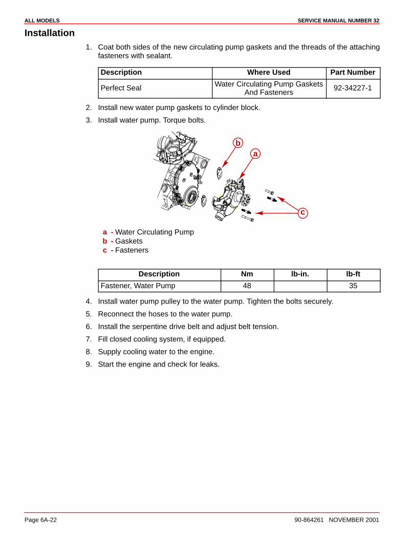
ALL MODELS SERVICE MANUAL NUMBER 32
Page 6A-22 90-864261 NOVEMBER 2001
Installation1. Coat both sides of the new circulating pump gaskets and the threads of the attaching
fasteners with sealant.
Description Where Used Part Number
Perfect Seal Water Circulating Pump GasketsAnd Fasteners
92-34227-1
2. Install new water pump gaskets to cylinder block.
3. Install water pump. Torque bolts.
ab
c
a - Water Circulating Pumpb - Gasketsc - Fasteners
Description Nm lb-in. lb-ft
Fastener, Water Pump 48 35
4. Install water pump pulley to the water pump. Tighten the bolts securely.
5. Reconnect the hoses to the water pump.
6. Install the serpentine drive belt and adjust belt tension.
7. Fill closed cooling system, if equipped.
8. Supply cooling water to the engine.
9. Start the engine and check for leaks.
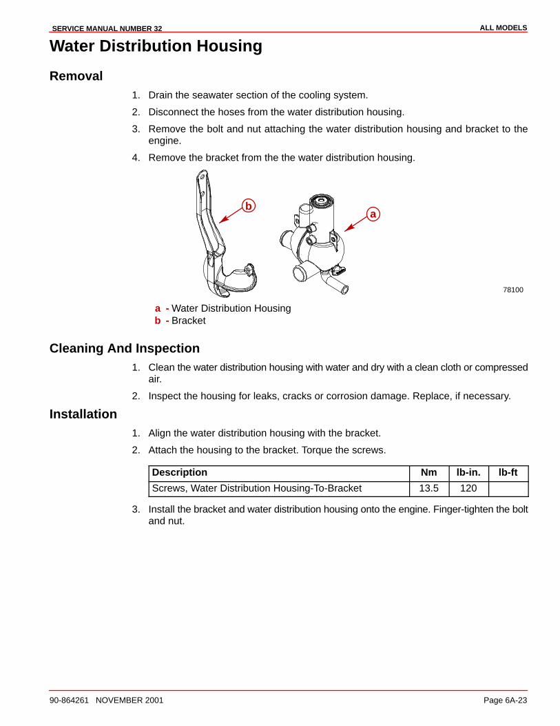
ALL MODELSSERVICE MANUAL NUMBER 32
90-864261 NOVEMBER 2001 Page 6A-23
Water Distribution Housing
Removal1. Drain the seawater section of the cooling system.
2. Disconnect the hoses from the water distribution housing.
3. Remove the bolt and nut attaching the water distribution housing and bracket to theengine.
4. Remove the bracket from the the water distribution housing.
78100
ab
a - Water Distribution Housingb - Bracket
Cleaning And Inspection1. Clean the water distribution housing with water and dry with a clean cloth or compressed
air.
2. Inspect the housing for leaks, cracks or corrosion damage. Replace, if necessary.
Installation1. Align the water distribution housing with the bracket.
2. Attach the housing to the bracket. Torque the screws.
Description Nm lb-in. lb-ft
Screws, Water Distribution Housing-To-Bracket 13.5 120
3. Install the bracket and water distribution housing onto the engine. Finger-tighten the boltand nut.
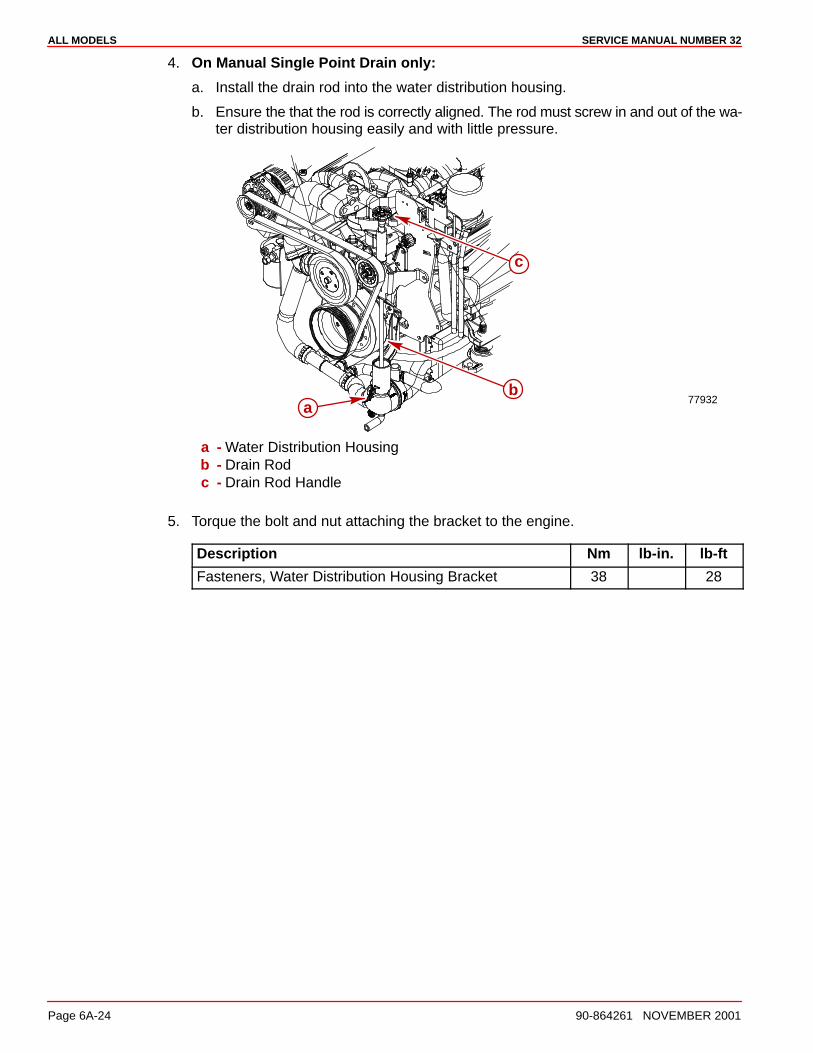
ALL MODELS SERVICE MANUAL NUMBER 32
Page 6A-24 90-864261 NOVEMBER 2001
4. On Manual Single Point Drain only:
a. Install the drain rod into the water distribution housing.
b. Ensure the that the rod is correctly aligned. The rod must screw in and out of the wa-ter distribution housing easily and with little pressure.
77932a
b
c
a - Water Distribution Housingb - Drain Rodc - Drain Rod Handle
5. Torque the bolt and nut attaching the bracket to the engine.
Description Nm lb-in. lb-ft
Fasteners, Water Distribution Housing Bracket 38 28
6B
SEAWATER COOLED MODELSSERVICE MANUAL NUMBER 32
90-864261 NOVEMBER 2001 Page 6B-1
COOLING SYSTEMSection 6B - Seawater Cooled Models
Table of Contents
Torque Specifications 6B-2. . . . . . . . . . . . . . . . Lubricants / Sealants / Adhesives 6B-2. . . . . Specifications 6B-2. . . . . . . . . . . . . . . . . . . . . . .
Seawater Cooling System Capacity 6B-2. Thermostat 6B-2. . . . . . . . . . . . . . . . . . . . . .
Flushing Seawater Cooling System 6B-3. . . . Thermostat 6B-3. . . . . . . . . . . . . . . . . . . . . . . . .
Removal 6B-3. . . . . . . . . . . . . . . . . . . . . . . . Testing 6B-4. . . . . . . . . . . . . . . . . . . . . . . . . . Installation 6B-5. . . . . . . . . . . . . . . . . . . . . . .
Water Flow Diagrams 6B-6. . . . . . . . . . . . . . . . Seawater Cooled Models With An Engine Mounted Seawater Pump 6B-6Seawater Cooled Models Without An Engine Mounted Seawater Pump 6B-7
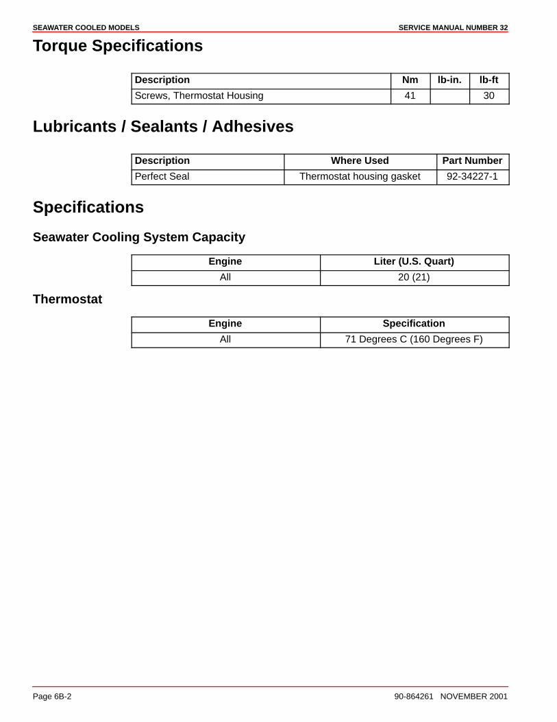
SEAWATER COOLED MODELS SERVICE MANUAL NUMBER 32
Page 6B-2 90-864261 NOVEMBER 2001
Torque Specifications
Description Nm lb-in. lb-ft
Screws, Thermostat Housing 41 30
Lubricants / Sealants / Adhesives
Description Where Used Part Number
Perfect Seal Thermostat housing gasket 92-34227-1
Specifications
Seawater Cooling System Capacity
Engine Liter (U.S. Quart)
All 20 (21)
Thermostat
Engine Specification
All 71 Degrees C (160 Degrees F)
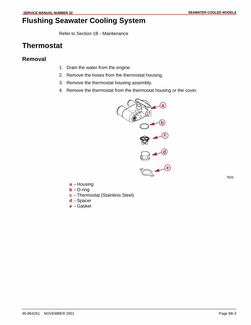
SEAWATER COOLED MODELSSERVICE MANUAL NUMBER 32
90-864261 NOVEMBER 2001 Page 6B-3
Flushing Seawater Cooling System
Refer to Section 1B - Maintenance
Thermostat
Removal1. Drain the water from the engine.
2. Remove the hoses from the thermostat housing.
3. Remove the thermostat housing assembly.
4. Remove the thermostat from the thermostat housing or the cover.
7825
a
b
c
e
d
a - Housingb - O-ringc - Thermostat (Stainless Steel)d - Spacere - Gasket

SEAWATER COOLED MODELS SERVICE MANUAL NUMBER 32
Page 6B-4 90-864261 NOVEMBER 2001
Testing1. Remove the thermostat.
2. Place the thermostat on blocks in a container.
3. Completely submerge the thermostat in water.
4. Heat the water.
5. Stir the water constantly to avoid direct heat being applied to the thermostat.
6. Refer to Specifications:
a. Check the thermostat initial opening temperature.
b. Check the thermostat full opening temperature.
c. Check valve lift at fully open position.
77724
a
b
dd
c
a - Thermometerb - Agitating Rodc - Wooden Blocksd - Thermostat
7. Replace if specifications are not met or damage is discovered during inspection.
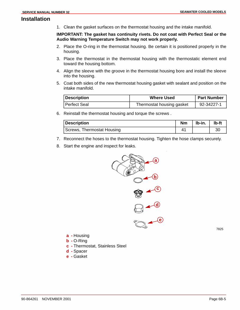
SEAWATER COOLED MODELSSERVICE MANUAL NUMBER 32
90-864261 NOVEMBER 2001 Page 6B-5
Installation1. Clean the gasket surfaces on the thermostat housing and the intake manifold.
IMPORTANT: The gasket has continuity rivets. Do not coat with Perfect Seal or theAudio Warning Temperature Switch may not work properly.
2. Place the O-ring in the thermostat housing. Be certain it is positioned properly in thehousing.
3. Place the thermostat in the thermostat housing with the thermostatic element endtoward the housing bottom.
4. Align the sleeve with the groove in the thermostat housing bore and install the sleeveinto the housing.
5. Coat both sides of the new thermostat housing gasket with sealant and position on theintake manifold.
Description Where Used Part Number
Perfect Seal Thermostat housing gasket 92-34227-1
6. Reinstall the thermostat housing and torque the screws .
Description Nm lb-in. lb-ft
Screws, Thermostat Housing 41 30
7. Reconnect the hoses to the thermostat housing. Tighten the hose clamps securely.
8. Start the engine and inspect for leaks.
7825
a
b
c
e
d
a - Housingb - O-Ringc - Thermostat, Stainless Steeld - Spacere - Gasket
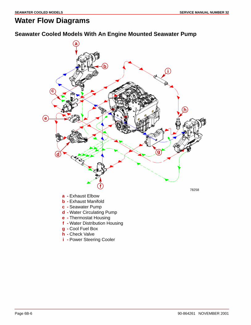
SEAWATER COOLED MODELS SERVICE MANUAL NUMBER 32
Page 6B-6 90-864261 NOVEMBER 2001
Water Flow Diagrams
Seawater Cooled Models With An Engine Mounted Seawater Pump
78258
a
b
c
f
g
h
i
e
d
a - Exhaust Elbowb - Exhaust Manifoldc - Seawater Pumpd - Water Circulating Pumpe - Thermostat Housingf - Water Distribution Housingg - Cool Fuel Boxh - Check Valvei - Power Steering Cooler
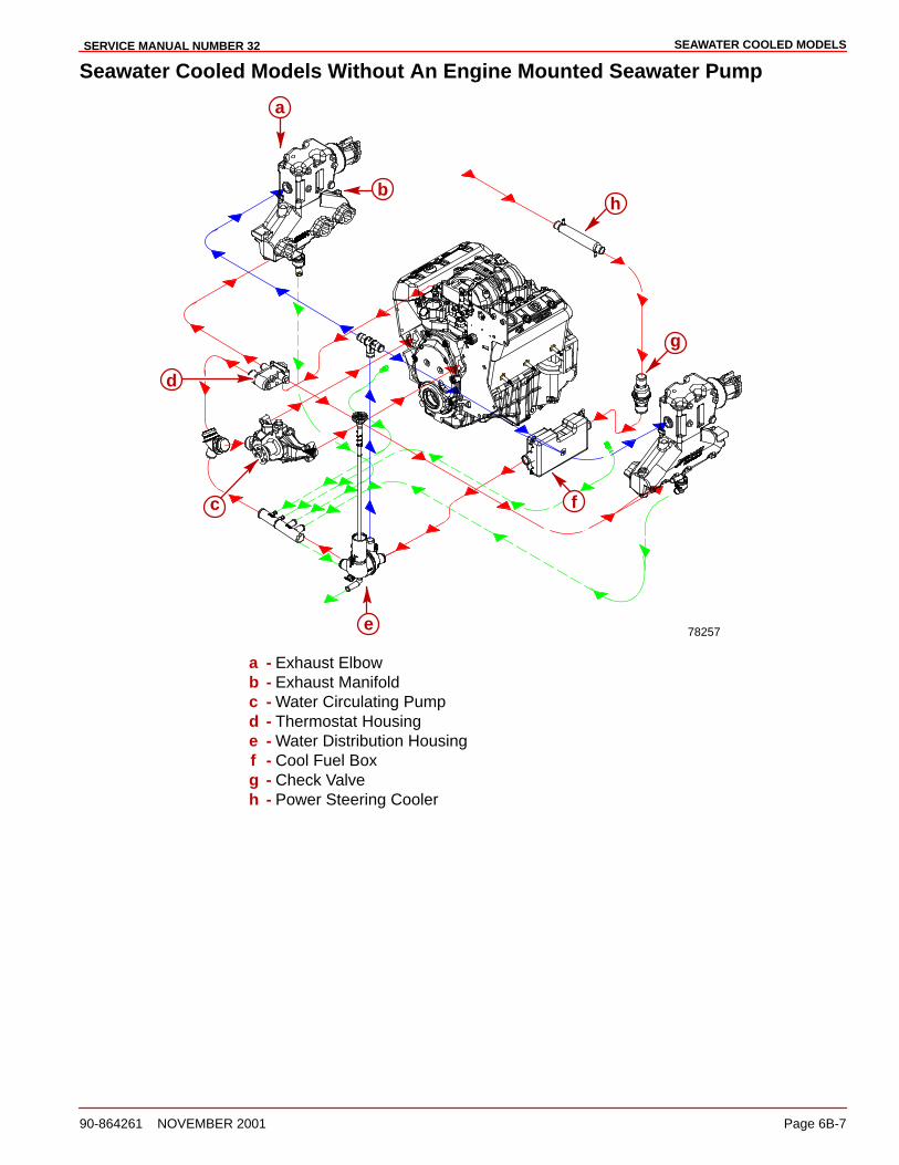
SEAWATER COOLED MODELSSERVICE MANUAL NUMBER 32
90-864261 NOVEMBER 2001 Page 6B-7
Seawater Cooled Models Without An Engine Mounted Seawater Pump
78257
a
b
f
g
h
e
d
c
a - Exhaust Elbowb - Exhaust Manifoldc - Water Circulating Pumpd - Thermostat Housinge - Water Distribution Housingf - Cool Fuel Boxg - Check Valveh - Power Steering Cooler
6C
CLOSED COOLED MODELSSERVICE MANUAL NUMBER 32
90-864261 NOVEMBER 2001 Page 6C-1
COOLING SYSTEMSection 6C - Closed Cooled Models
Table of Contents
Torque Specifications 6C-2. . . . . . . . . . . . . . . . Lubricants / Sealants / Adhesives 6C-2. . . . . Specifications 6C-2. . . . . . . . . . . . . . . . . . . . . . .
Closed Cooling System Capacity 6C-2. . . Coolant Specification 6C-2. . . . . . . . . . . . . . Thermostat 6C-2. . . . . . . . . . . . . . . . . . . . . . Pressure Cap Rating 6C-2. . . . . . . . . . . . . .
Description 6C-3. . . . . . . . . . . . . . . . . . . . . . . . . Coolant Recommendations 6C-3. . . . . . . . . . . Maintaining Coolant Level 6C-4. . . . . . . . . . . . Pressure Cap Maintenance 6C-5. . . . . . . . . . . Testing Closed Cooling System 6C-6. . . . . . .
Testing Coolant for Alkalinity 6C-6. . . . . . . Pressure Testing System 6C-7. . . . . . . . . . Testing for Cylinder Head Gasket Leak 6C-9. . . . . . . . . . . . . . . . . . . . . Testing Pressure Cap 6C-10. . . . . . . . . . . . .
Thermostat 6C-12. . . . . . . . . . . . . . . . . . . . . . . . . Removal 6C-12. . . . . . . . . . . . . . . . . . . . . . . . . Testing 6C-12. . . . . . . . . . . . . . . . . . . . . . . . . . Installation 6C-14. . . . . . . . . . . . . . . . . . . . . . .
Heat Exchanger 6C-15. . . . . . . . . . . . . . . . . . . . . Testing 6C-15. . . . . . . . . . . . . . . . . . . . . . . . . . Removal 6C-15. . . . . . . . . . . . . . . . . . . . . . . . . Disassembly 6C-16. . . . . . . . . . . . . . . . . . . . . Cleaning And Inspection 6C-16. . . . . . . . . . . Repair 6C-16. . . . . . . . . . . . . . . . . . . . . . . . . . . Assembly 6C-17. . . . . . . . . . . . . . . . . . . . . . . . Installation 6C-18. . . . . . . . . . . . . . . . . . . . . . .
Heat Exchanger Bracket Hardware 6C-19. . . . Heat Exchanger Hose Connections 6C-20. . . . Closed Cooling System Water Flow Diagram 6C-21. . . . . . . . . . . . . . . . . . . . . . . . . . .
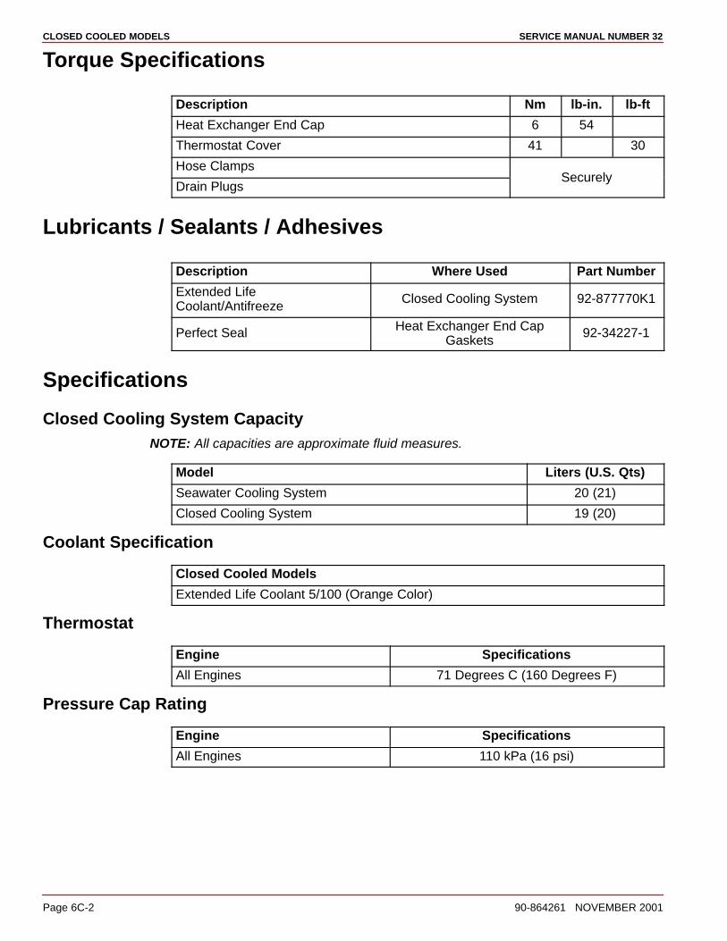
CLOSED COOLED MODELS SERVICE MANUAL NUMBER 32
Page 6C-2 90-864261 NOVEMBER 2001
Torque Specifications
Description Nm lb-in. lb-ft
Heat Exchanger End Cap 6 54
Thermostat Cover 41 30
Hose Clamps
Drain PlugsSecurely
Lubricants / Sealants / Adhesives
Description Where Used Part Number
Extended LifeCoolant/Antifreeze
Closed Cooling System 92-877770K1
Perfect Seal Heat Exchanger End CapGaskets
92-34227-1
Specifications
Closed Cooling System CapacityNOTE: All capacities are approximate fluid measures.
Model Liters (U.S. Qts)
Seawater Cooling System 20 (21)
Closed Cooling System 19 (20)
Coolant Specification
Closed Cooled Models
Extended Life Coolant 5/100 (Orange Color)
Thermostat
Engine Specifications
All Engines 71 Degrees C (160 Degrees F)
Pressure Cap Rating
Engine Specifications
All Engines 110 kPa (16 psi)
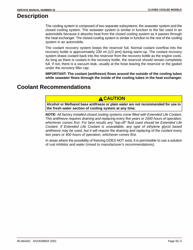
CLOSED COOLED MODELSSERVICE MANUAL NUMBER 32
90-864261 NOVEMBER 2001 Page 6C-3
Description
The cooling system is composed of two separate subsystems: the seawater system and theclosed cooling system. The seawater system is similar in function to the fan used in anautomobile because it absorbs heat from the closed cooling system as it passes throughthe heat exchanger. The closed cooling system is similar in function to the rest of the coolingsystem in an automobile.
The coolant recovery system keeps the reservoir full. Normal coolant overflow into therecovery bottle is approximately 230 ml (1/2 pint) during warm-up. The coolant recoverysystem draws coolant back into the reservoir from the recovery bottle as the engine cools.As long as there is coolant in the recovery bottle, the reservoir should remain completelyfull. If not, there is a vacuum leak, usually at the hose leaving the reservoir or the gasketunder the recovery filler cap.
IMPORTANT: The coolant (antifreeze) flows around the outside of the cooling tubeswhile seawater flows through the inside of the cooling tubes in the heat exchanger.
Coolant Recommendations
CAUTIONAlcohol or Methanol base antifreeze or plain water are not recommended for use inthe fresh water section of cooling system at any time.
NOTE: All factory installed closed cooling systems come filled with Extended Life Coolant.This antifreeze requires draining and replacing every five years or 1000 hours of operation,whichever comes first. For best results any “top-off” fluid used should be Extended LifeCoolant. If Extended Life Coolant is unavailable, any type of ethylene glycol basedantifreeze may be used, but it will require the draining and replacing of the coolant everytwo years or 400 hours of operation, whichever comes first.
In areas where the possibility of freezing DOES NOT exist, it is permissible to use a solutionof rust inhibitor and water (mixed to manufacturer’s recommendations).
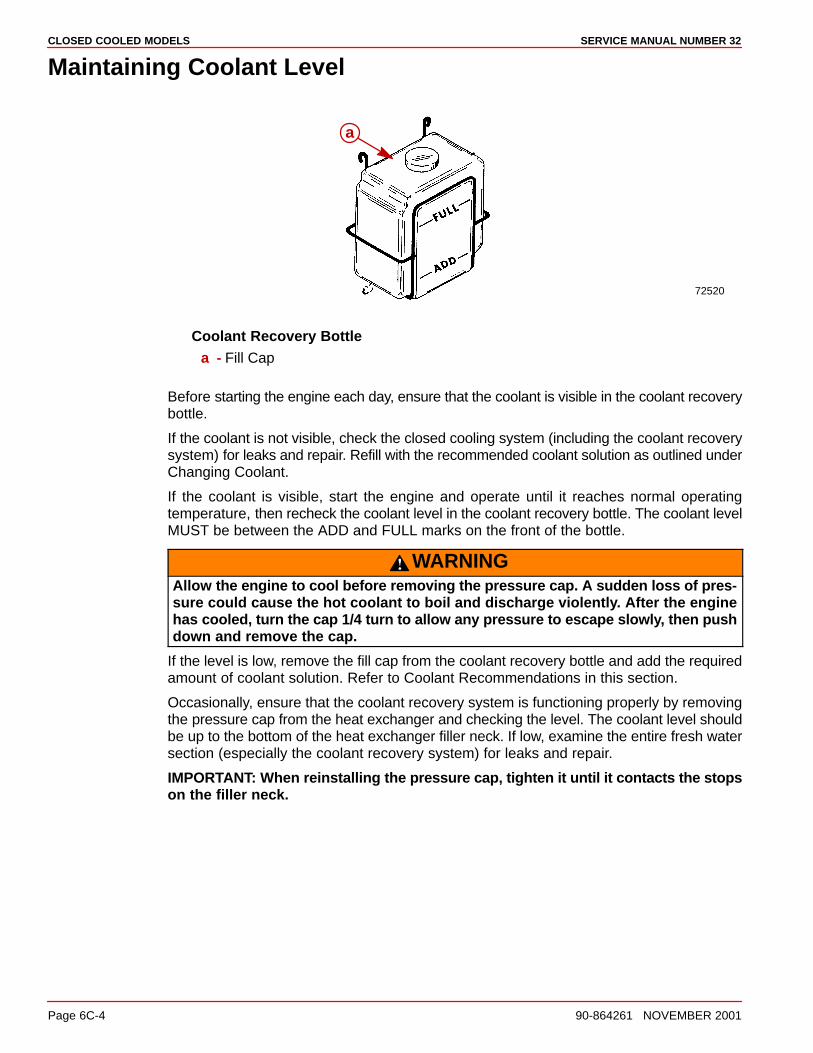
CLOSED COOLED MODELS SERVICE MANUAL NUMBER 32
Page 6C-4 90-864261 NOVEMBER 2001
Maintaining Coolant Level
72520
a
Coolant Recovery Bottlea - Fill Cap
Before starting the engine each day, ensure that the coolant is visible in the coolant recoverybottle.
If the coolant is not visible, check the closed cooling system (including the coolant recoverysystem) for leaks and repair. Refill with the recommended coolant solution as outlined underChanging Coolant.
If the coolant is visible, start the engine and operate until it reaches normal operatingtemperature, then recheck the coolant level in the coolant recovery bottle. The coolant levelMUST be between the ADD and FULL marks on the front of the bottle.
WARNINGAllow the engine to cool before removing the pressure cap. A sudden loss of pres-sure could cause the hot coolant to boil and discharge violently. After the enginehas cooled, turn the cap 1/4 turn to allow any pressure to escape slowly, then pushdown and remove the cap.
If the level is low, remove the fill cap from the coolant recovery bottle and add the requiredamount of coolant solution. Refer to Coolant Recommendations in this section.
Occasionally, ensure that the coolant recovery system is functioning properly by removingthe pressure cap from the heat exchanger and checking the level. The coolant level shouldbe up to the bottom of the heat exchanger filler neck. If low, examine the entire fresh watersection (especially the coolant recovery system) for leaks and repair.
IMPORTANT: When reinstalling the pressure cap, tighten it until it contacts the stopson the filler neck.
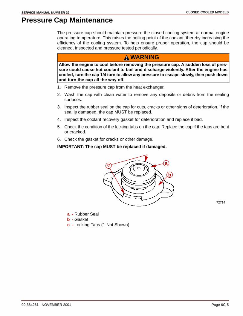
CLOSED COOLED MODELSSERVICE MANUAL NUMBER 32
90-864261 NOVEMBER 2001 Page 6C-5
Pressure Cap Maintenance
The pressure cap should maintain pressure the closed cooling system at normal engineoperating temperature. This raises the boiling point of the coolant, thereby increasing theefficiency of the cooling system. To help ensure proper operation, the cap should becleaned, inspected and pressure tested periodically.
WARNINGAllow the engine to cool before removing the pressure cap. A sudden loss of pres-sure could cause hot coolant to boil and discharge violently. After the engine hascooled, turn the cap 1/4 turn to allow any pressure to escape slowly, then push downand turn the cap all the way off.
1. Remove the pressure cap from the heat exchanger.
2. Wash the cap with clean water to remove any deposits or debris from the sealingsurfaces.
3. Inspect the rubber seal on the cap for cuts, cracks or other signs of deterioration. If theseal is damaged, the cap MUST be replaced.
4. Inspect the coolant recovery gasket for deterioration and replace if bad.
5. Check the condition of the locking tabs on the cap. Replace the cap if the tabs are bentor cracked.
6. Check the gasket for cracks or other damage.
IMPORTANT: The cap MUST be replaced if damaged.
72714
a
b
c
a - Rubber Sealb - Gasketc - Locking Tabs (1 Not Shown)
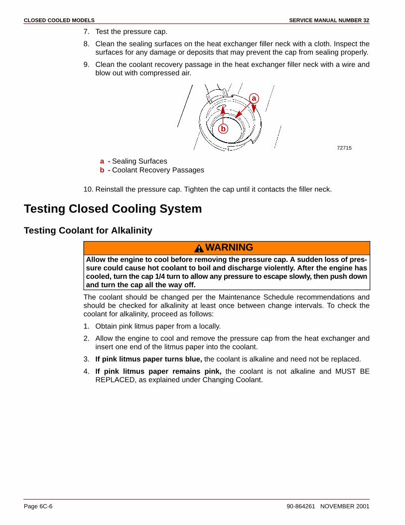
CLOSED COOLED MODELS SERVICE MANUAL NUMBER 32
Page 6C-6 90-864261 NOVEMBER 2001
7. Test the pressure cap.
8. Clean the sealing surfaces on the heat exchanger filler neck with a cloth. Inspect thesurfaces for any damage or deposits that may prevent the cap from sealing properly.
9. Clean the coolant recovery passage in the heat exchanger filler neck with a wire andblow out with compressed air.
72715
a
b
a - Sealing Surfacesb - Coolant Recovery Passages
10. Reinstall the pressure cap. Tighten the cap until it contacts the filler neck.
Testing Closed Cooling System
Testing Coolant for Alkalinity
WARNINGAllow the engine to cool before removing the pressure cap. A sudden loss of pres-sure could cause hot coolant to boil and discharge violently. After the engine hascooled, turn the cap 1/4 turn to allow any pressure to escape slowly, then push downand turn the cap all the way off.
The coolant should be changed per the Maintenance Schedule recommendations andshould be checked for alkalinity at least once between change intervals. To check thecoolant for alkalinity, proceed as follows:
1. Obtain pink litmus paper from a locally.
2. Allow the engine to cool and remove the pressure cap from the heat exchanger andinsert one end of the litmus paper into the coolant.
3. If pink litmus paper turns blue, the coolant is alkaline and need not be replaced.
4. If pink litmus paper remains pink, the coolant is not alkaline and MUST BEREPLACED, as explained under Changing Coolant.
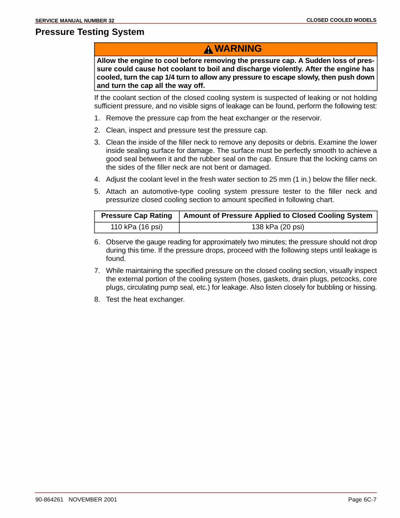
CLOSED COOLED MODELSSERVICE MANUAL NUMBER 32
90-864261 NOVEMBER 2001 Page 6C-7
Pressure Testing System
WARNINGAllow the engine to cool before removing the pressure cap. A Sudden loss of pres-sure could cause hot coolant to boil and discharge violently. After the engine hascooled, turn the cap 1/4 turn to allow any pressure to escape slowly, then push downand turn the cap all the way off.
If the coolant section of the closed cooling system is suspected of leaking or not holdingsufficient pressure, and no visible signs of leakage can be found, perform the following test:
1. Remove the pressure cap from the heat exchanger or the reservoir.
2. Clean, inspect and pressure test the pressure cap.
3. Clean the inside of the filler neck to remove any deposits or debris. Examine the lowerinside sealing surface for damage. The surface must be perfectly smooth to achieve agood seal between it and the rubber seal on the cap. Ensure that the locking cams onthe sides of the filler neck are not bent or damaged.
4. Adjust the coolant level in the fresh water section to 25 mm (1 in.) below the filler neck.
5. Attach an automotive-type cooling system pressure tester to the filler neck andpressurize closed cooling section to amount specified in following chart.
Pressure Cap Rating Amount of Pressure Applied to Closed Cooling System
110 kPa (16 psi) 138 kPa (20 psi)
6. Observe the gauge reading for approximately two minutes; the pressure should not dropduring this time. If the pressure drops, proceed with the following steps until leakage isfound.
7. While maintaining the specified pressure on the closed cooling section, visually inspectthe external portion of the cooling system (hoses, gaskets, drain plugs, petcocks, coreplugs, circulating pump seal, etc.) for leakage. Also listen closely for bubbling or hissing.
8. Test the heat exchanger.
CLOSED COOLED MODELS SERVICE MANUAL NUMBER 32
Page 6C-8 90-864261 NOVEMBER 2001
9. If no leakage could be found in the above steps, the engine is leaking internally. Leakingmay be caused by one or more of the following: loose cylinder head bolts or damagedgasket, loose intake manifold bolts or damaged gasket, loose exhaust elbow ordistribution block retaining nuts or damaged gasket, cracked or porous cylinder heador block or cracked or porous exhaust manifold. Proceed as follows until the location ofthe internal leak is found.
a. Start the engine. Re-pressurize the system to the previously specified amount andobserve the pressure gauge on the tester. If the needle in the gauge vibrates, thecompression or the combustion is leaking into the closed cooling section from a leakin the combustion chamber. Exact cylinders where the leakage is taking place cansometimes be found by removing the spark plug wires (one at a time) whileobserving the pressure gauge. Vibration will decrease or stop when the plug wireis removed from the leaking cylinder. Stop the engine.
b. Remove the spark plugs (one at a time) from the cylinders and examine for thepresence of coolant. A spark plug that is perfectly clean or milky appearing is a sureindication of a leak.
c. Drain the oil from the engine and examine for coolant. Oil will usually be milky ifcoolant is present. If coolant is present, remove the engine from the boat and dropthe oil pan. With the engine in the upright position, re-pressurize the closed coolingsection to the previously specified amount and examine the internal surfaces of theengine to locate the leak.
d. If no leakage can be found in the above steps, the entire engine must bedisassembled and inspected for leaks.
CLOSED COOLED MODELSSERVICE MANUAL NUMBER 32
90-864261 NOVEMBER 2001 Page 6C-9
Testing for Cylinder Head Gasket LeakA leaking head gasket will cause combustion gas to be forced into the cooling system. Themixture of coolant and tiny air bubbles is a poor heat conductor and will overheat an enginequickly. Compression tests or cooling system pressure check normally will not detect theleak because the test pressure is far below the combustion pressures that cause the leak.An effective test is as follows:
IMPORTANT: Operate the boat in the water for this test. It is best to operate the engineat or above cruising speed during this test. Usually a failed head gasket will not causethe engine to overheat below cruising speed.
1. Install a clear plastic hose between the reservoir and the coolant recovery bottle. Usea 610-910 mm (2-3 ft) long hose for this test.
2. Route this hose so a U is formed.
3. Put enough coolant into the hose to fill the center 100-130 mm (4-5 in.) of the U-shape.
4. Observe the U-shape while the engine is operating.
a. During Idle and Warm-Up: Some coolant and/or air will leave the reservoir.
b. During Cruising Speed (2500-3500 rpm): Coolant and/or air leaving the reservoirshould stop after approximately five minutes operating at a given rpm. A leakinghead gasket will produce air bubbling through the U-shape, going to the coolantrecovery bottle. The frequency and size of the bubbles will depend on the size of theleak.
c. At Higher Speeds (4000+ rpm): Normal operation is the same as described above.A failed head gasket will cause the bubbles to come faster and may be accompaniedby violent, intermittent bursts of coolant.
Do not confuse normal warm-up expansion with a failed head gasket. Normal warm-upproduces an intermittent flow of coolant that will stop within approximately five minutes ata given rpm. A head gasket leak will not stop because the one thing that marks a failed headgasket is the continued passage of air. This may be accompanied by violent, intermittentbursts of coolant leaving the reservoir. If coolant flows evenly from the reservoir at cruisingspeed, something other than the head gasket is causing the engine to overheat.
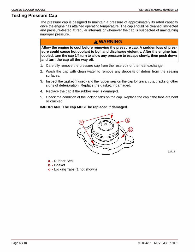
CLOSED COOLED MODELS SERVICE MANUAL NUMBER 32
Page 6C-10 90-864261 NOVEMBER 2001
Testing Pressure CapThe pressure cap is designed to maintain a pressure of approximately its rated capacityonce the engine has attained operating temperature. The cap should be cleaned, inspectedand pressure-tested at regular intervals or whenever the cap is suspected of maintainingimproper pressure.
WARNINGAllow the engine to cool before removing the pressure cap. A sudden loss of pres-sure could cause hot coolant to boil and discharge violently. After the engine hascooled, turn the cap 1/4 turn to allow any pressure to escape slowly, then push downand turn the cap all the way off.
1. Carefully remove the pressure cap from the reservoir or the heat exchanger.
2. Wash the cap with clean water to remove any deposits or debris from the sealingsurfaces.
3. Inspect the gasket (if used) and the rubber seal on the cap for tears, cuts, cracks or othersigns of deterioration. Replace the gasket, if damaged.
4. Replace the cap if the rubber seal is damaged.
5. Check the condition of the locking tabs on the cap. Replace the cap if the tabs are bentor cracked.
IMPORTANT: The cap MUST be replaced if damaged.
72714
a
b
c
a - Rubber Sealb - Gasketc - Locking Tabs (1 not shown)
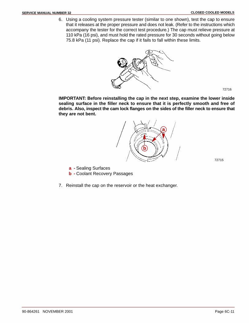
CLOSED COOLED MODELSSERVICE MANUAL NUMBER 32
90-864261 NOVEMBER 2001 Page 6C-11
6. Using a cooling system pressure tester (similar to one shown), test the cap to ensurethat it releases at the proper pressure and does not leak. (Refer to the instructions whichaccompany the tester for the correct test procedure.) The cap must relieve pressure at110 kPa (16 psi), and must hold the rated pressure for 30 seconds without going below75.8 kPa (11 psi). Replace the cap if it fails to fall within these limits.
72716
IMPORTANT: Before reinstalling the cap in the next step, examine the lower insidesealing surface in the filler neck to ensure that it is perfectly smooth and free ofdebris. Also, inspect the cam lock flanges on the sides of the filler neck to ensure thatthey are not bent.
72715
a
b
a - Sealing Surfacesb - Coolant Recovery Passages
7. Reinstall the cap on the reservoir or the heat exchanger.
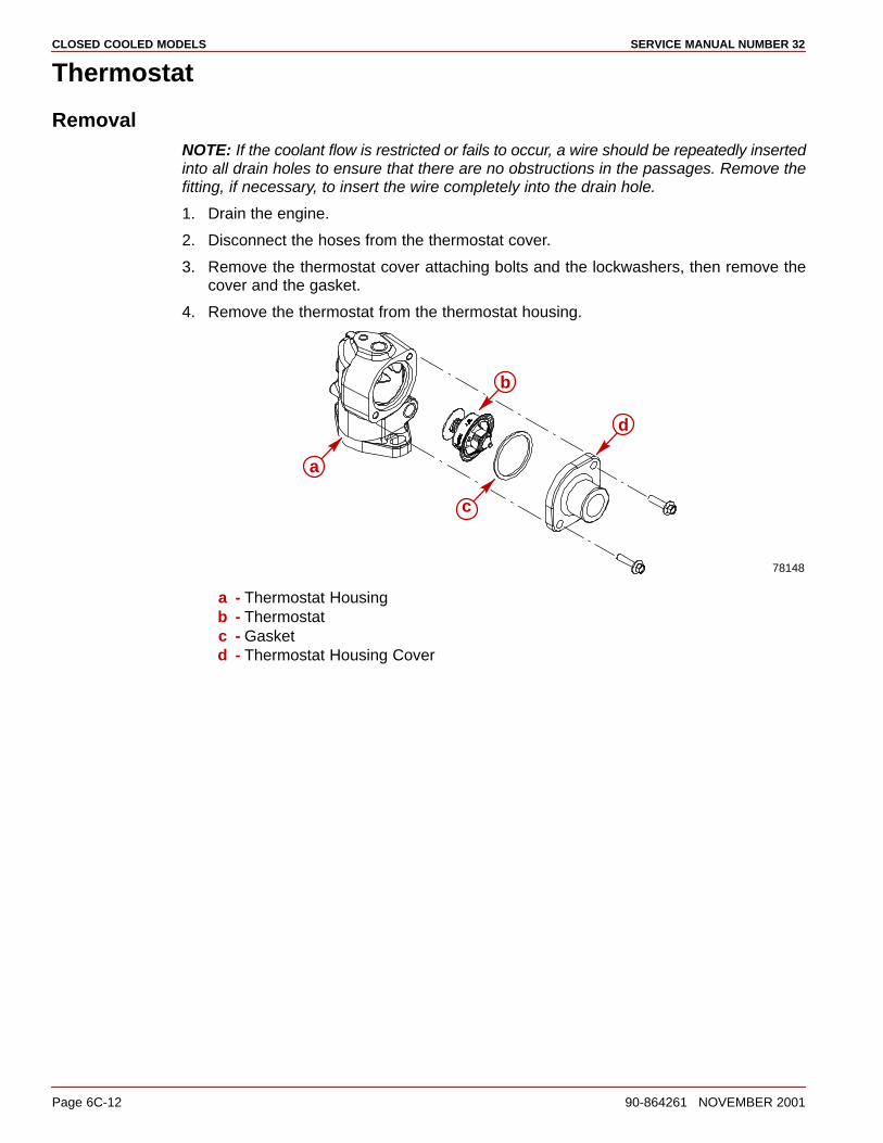
CLOSED COOLED MODELS SERVICE MANUAL NUMBER 32
Page 6C-12 90-864261 NOVEMBER 2001
Thermostat
RemovalNOTE: If the coolant flow is restricted or fails to occur, a wire should be repeatedly insertedinto all drain holes to ensure that there are no obstructions in the passages. Remove thefitting, if necessary, to insert the wire completely into the drain hole.
1. Drain the engine.
2. Disconnect the hoses from the thermostat cover.
3. Remove the thermostat cover attaching bolts and the lockwashers, then remove thecover and the gasket.
4. Remove the thermostat from the thermostat housing.
a
c
b
d
78148
a - Thermostat Housingb - Thermostatc - Gasketd - Thermostat Housing Cover
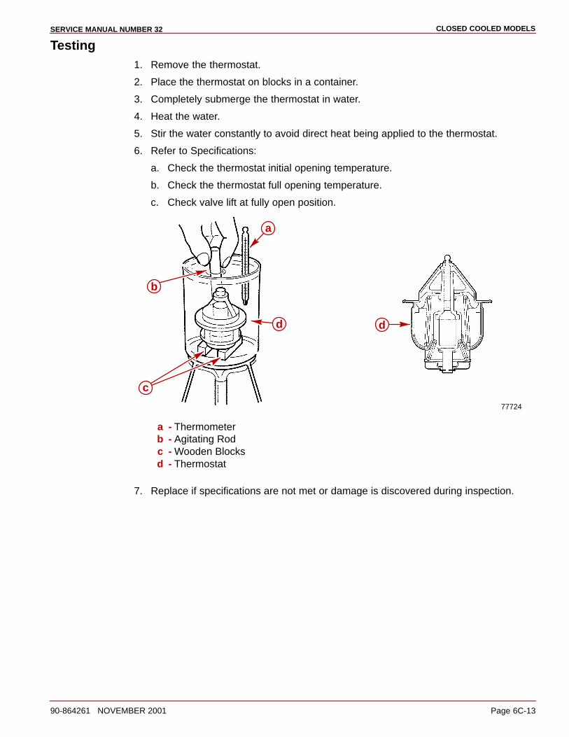
CLOSED COOLED MODELSSERVICE MANUAL NUMBER 32
90-864261 NOVEMBER 2001 Page 6C-13
Testing1. Remove the thermostat.
2. Place the thermostat on blocks in a container.
3. Completely submerge the thermostat in water.
4. Heat the water.
5. Stir the water constantly to avoid direct heat being applied to the thermostat.
6. Refer to Specifications:
a. Check the thermostat initial opening temperature.
b. Check the thermostat full opening temperature.
c. Check valve lift at fully open position.
77724
a
b
dd
c
a - Thermometerb - Agitating Rodc - Wooden Blocksd - Thermostat
7. Replace if specifications are not met or damage is discovered during inspection.

CLOSED COOLED MODELS SERVICE MANUAL NUMBER 32
Page 6C-14 90-864261 NOVEMBER 2001
Installation
CAUTIONAvoid seawater pickup pump impeller damage. DO NOT operate the engine withoutcooling water being supplied to the seawater pickup pump.
1. Remove the thermostat housing and the gaskets. Discard the gaskets.
2. Clean the gasket surfaces on the thermostat cover, the thermostat housing and theintake manifold.
3. Position the gasket on the intake manifold. Place the thermostat housing on the gasket.
IMPORTANT: If the gasket has continuity rivets, do NOT coat with Perfect Seal, or theaudio warning temperature switch may not work properly.
4. Install the thermostat into the thermostat housing.
5. Position the gasket on the thermostat and reinstall the thermostat cover. Torque thebolts.
a
c
b
d
78148
a - Thermostat Housingb - Thermostatc - Gasketd - Thermostat Housing Cover
Description Nm lb-in. lb-ft
Bolt, Thermostat Cover 41 30
6. Connect the hoses to the thermostat cover. Tighten the hose clamps securely.
7. Supply cooling water start the engine and inspect for leaks.
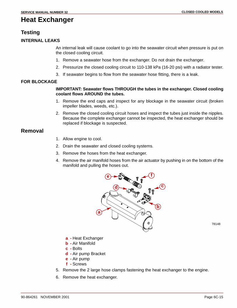
CLOSED COOLED MODELSSERVICE MANUAL NUMBER 32
90-864261 NOVEMBER 2001 Page 6C-15
Heat Exchanger
TestingINTERNAL LEAKS
An internal leak will cause coolant to go into the seawater circuit when pressure is put onthe closed cooling circuit.
1. Remove a seawater hose from the exchanger. Do not drain the exchanger.
2. Pressurize the closed cooling circuit to 110-138 kPa (16-20 psi) with a radiator tester.
3. If seawater begins to flow from the seawater hose fitting, there is a leak.
FOR BLOCKAGE
IMPORTANT: Seawater flows THROUGH the tubes in the exchanger. Closed coolingcoolant flows AROUND the tubes.
1. Remove the end caps and inspect for any blockage in the seawater circuit (brokenimpeller blades, weeds, etc.).
2. Remove the closed cooling circuit hoses and inspect the tubes just inside the nipples.Because the complete exchanger cannot be inspected, the heat exchanger should bereplaced if blockage is suspected.
Removal1. Allow engine to cool.
2. Drain the seawater and closed cooling systems.
3. Remove the hoses from the heat exchanger.
4. Remove the air manifold hoses from the air actuator by pushing in on the bottom of themanifold and pulling the hoses out.
78148
a
cd
e f
b
a - Heat Exchangerb - Air Manifoldc - Boltsd - Air pump Brackete - Air pumpf - Screws
5. Remove the 2 large hose clamps fastening the heat exchanger to the engine.
6. Remove the heat exchanger.
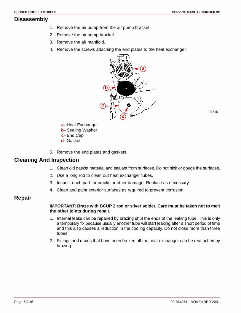
CLOSED COOLED MODELS SERVICE MANUAL NUMBER 32
Page 6C-16 90-864261 NOVEMBER 2001
Disassembly1. Remove the air pump from the air pump bracket.
2. Remove the air pump bracket.
3. Remove the air manifold.
4. Remove the screws attaching the end plates to the heat exchanger.
71515
b
c
d
a
a- Heat Exchangerb- Sealing Washerc- End Capd- Gasket
5. Remove the end plates and gaskets.
Cleaning And Inspection1. Clean old gasket material and sealant from surfaces. Do not nick or gouge the surfaces.
2. Use a long rod to clean out heat exchanger tubes.
3. Inspect each part for cracks or other damage. Replace as necessary.
4. Clean and paint exterior surfaces as required to prevent corrosion.
RepairIMPORTANT: Braze with BCUP 2 rod or silver solder. Care must be taken not to meltthe other joints during repair.
1. Internal leaks can be repaired by brazing shut the ends of the leaking tube. This is onlya temporary fix because usually another tube will start leaking after a short period of timeand this also causes a reduction in the cooling capacity. Do not close more than threetubes.
2. Fittings and drains that have been broken off the heat exchanger can be reattached bybrazing.
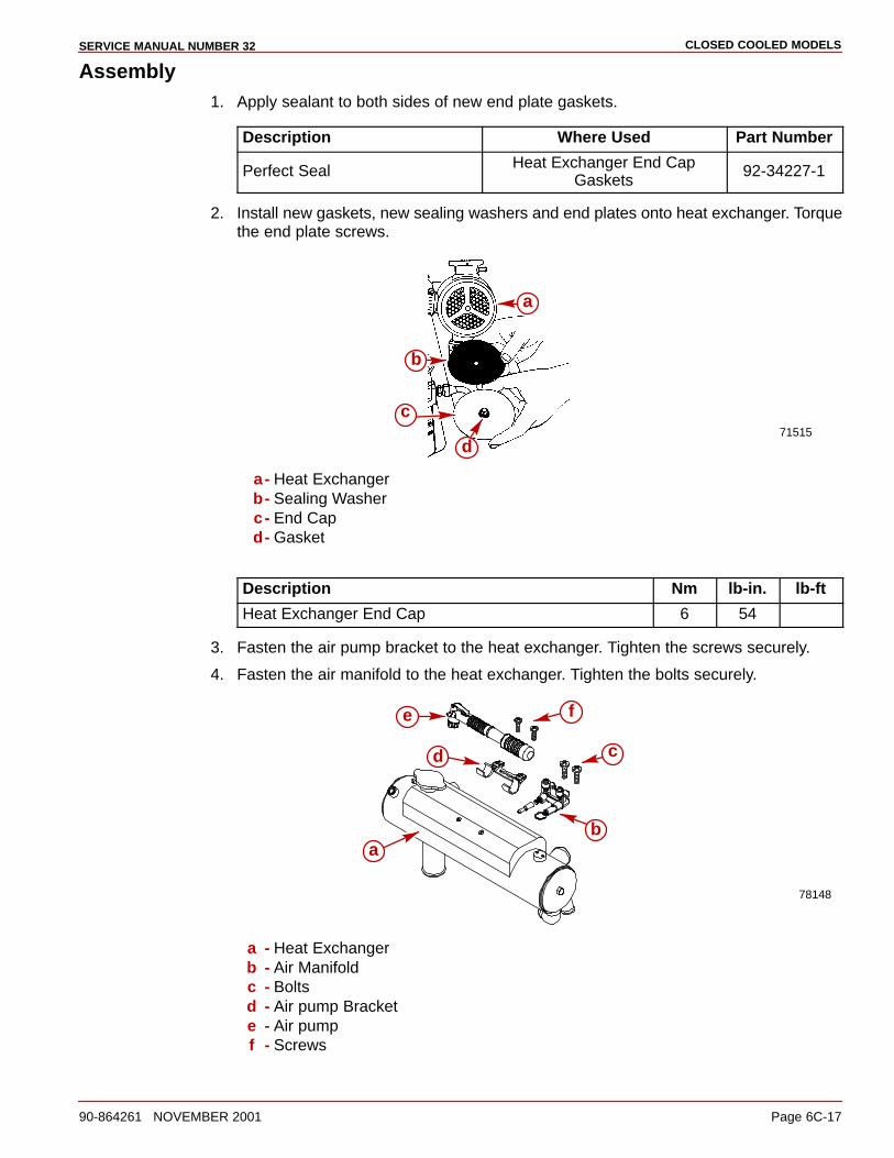
CLOSED COOLED MODELSSERVICE MANUAL NUMBER 32
90-864261 NOVEMBER 2001 Page 6C-17
Assembly1. Apply sealant to both sides of new end plate gaskets.
Description Where Used Part Number
Perfect Seal Heat Exchanger End CapGaskets
92-34227-1
2. Install new gaskets, new sealing washers and end plates onto heat exchanger. Torquethe end plate screws.
71515
b
c
d
a
a- Heat Exchangerb- Sealing Washerc- End Capd- Gasket
Description Nm lb-in. lb-ft
Heat Exchanger End Cap 6 54
3. Fasten the air pump bracket to the heat exchanger. Tighten the screws securely.
4. Fasten the air manifold to the heat exchanger. Tighten the bolts securely.
78148
a
cd
e f
b
a - Heat Exchangerb - Air Manifoldc - Boltsd - Air pump Brackete - Air pumpf - Screws
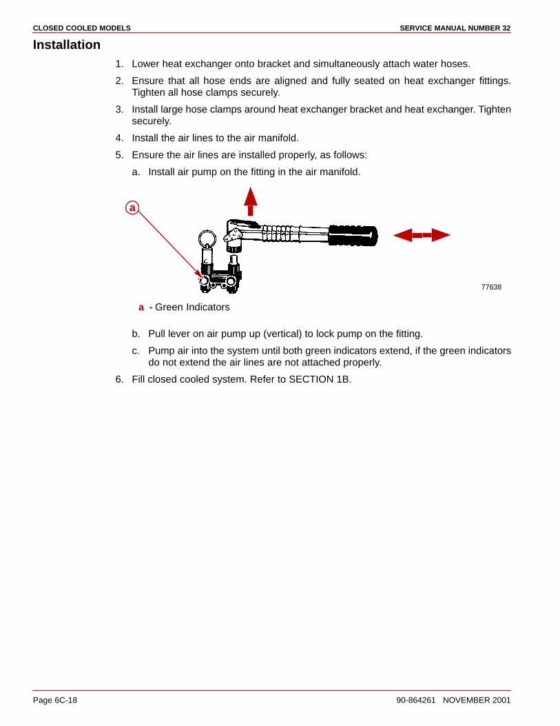
CLOSED COOLED MODELS SERVICE MANUAL NUMBER 32
Page 6C-18 90-864261 NOVEMBER 2001
Installation1. Lower heat exchanger onto bracket and simultaneously attach water hoses.
2. Ensure that all hose ends are aligned and fully seated on heat exchanger fittings.Tighten all hose clamps securely.
3. Install large hose clamps around heat exchanger bracket and heat exchanger. Tightensecurely.
4. Install the air lines to the air manifold.
5. Ensure the air lines are installed properly, as follows:
a. Install air pump on the fitting in the air manifold.
77638
a
a - Green Indicators
b. Pull lever on air pump up (vertical) to lock pump on the fitting.
c. Pump air into the system until both green indicators extend, if the green indicatorsdo not extend the air lines are not attached properly.
6. Fill closed cooled system. Refer to SECTION 1B.
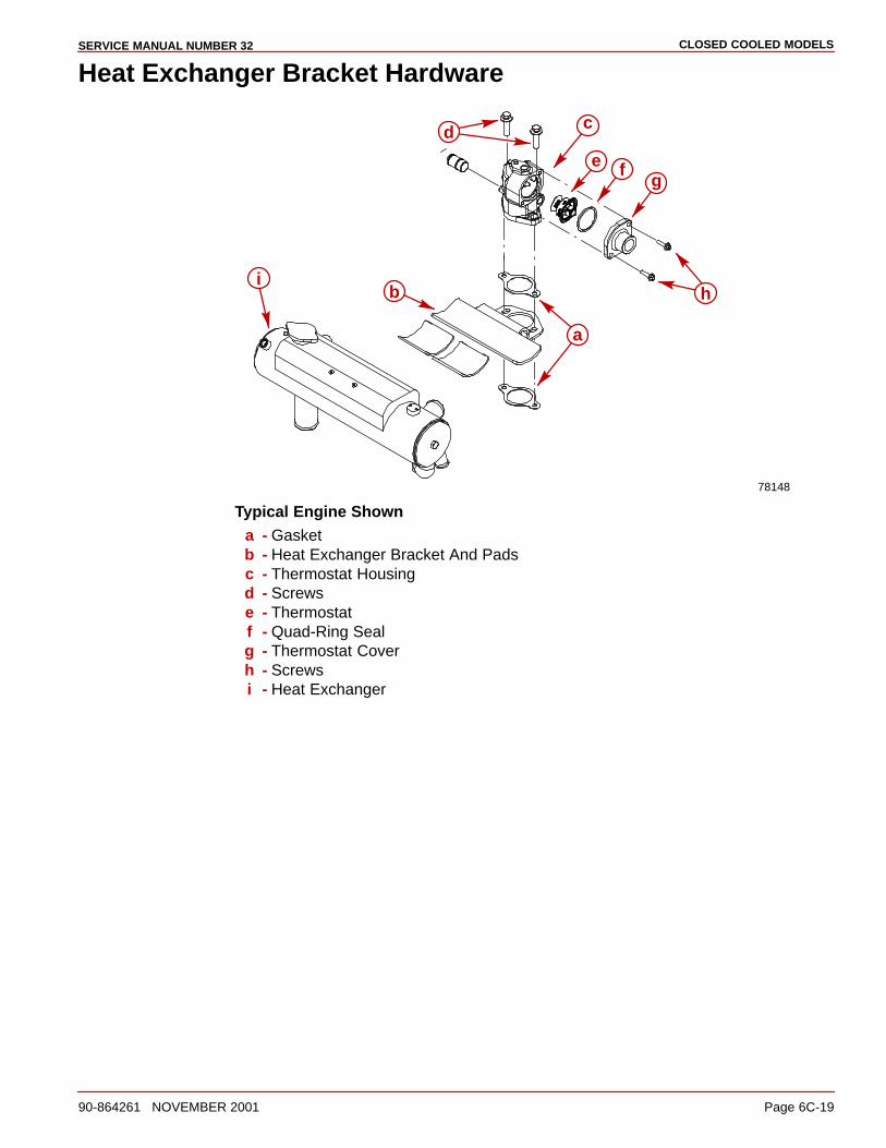
CLOSED COOLED MODELSSERVICE MANUAL NUMBER 32
90-864261 NOVEMBER 2001 Page 6C-19
Heat Exchanger Bracket Hardware
78148
a
d
b
c
fg
i
e
h
Typical Engine Showna - Gasketb - Heat Exchanger Bracket And Padsc - Thermostat Housingd - Screwse - Thermostatf - Quad-Ring Sealg - Thermostat Coverh - Screwsi - Heat Exchanger

CLOSED COOLED MODELS SERVICE MANUAL NUMBER 32
Page 6C-20 90-864261 NOVEMBER 2001
Heat Exchanger Hose Connections
77954
a
b
c
d
e
f
g
Typical Engine Showna - Heat Exchangerb - Starboard Heat Exchanger-To-Exhaust Manifold Hosec - Water Circulating Pump Hosed - Port Heat Exchanger-To-Exhaust Manifold Hose (MCM)e - Cool Fuel System-To-Heat Exchanger Hosef - Heat Exchanger Bypass Hoseg - Coolant Identification Decalh - Thermostat Housing-To-Heat Exchanger Hose (Not Visible)
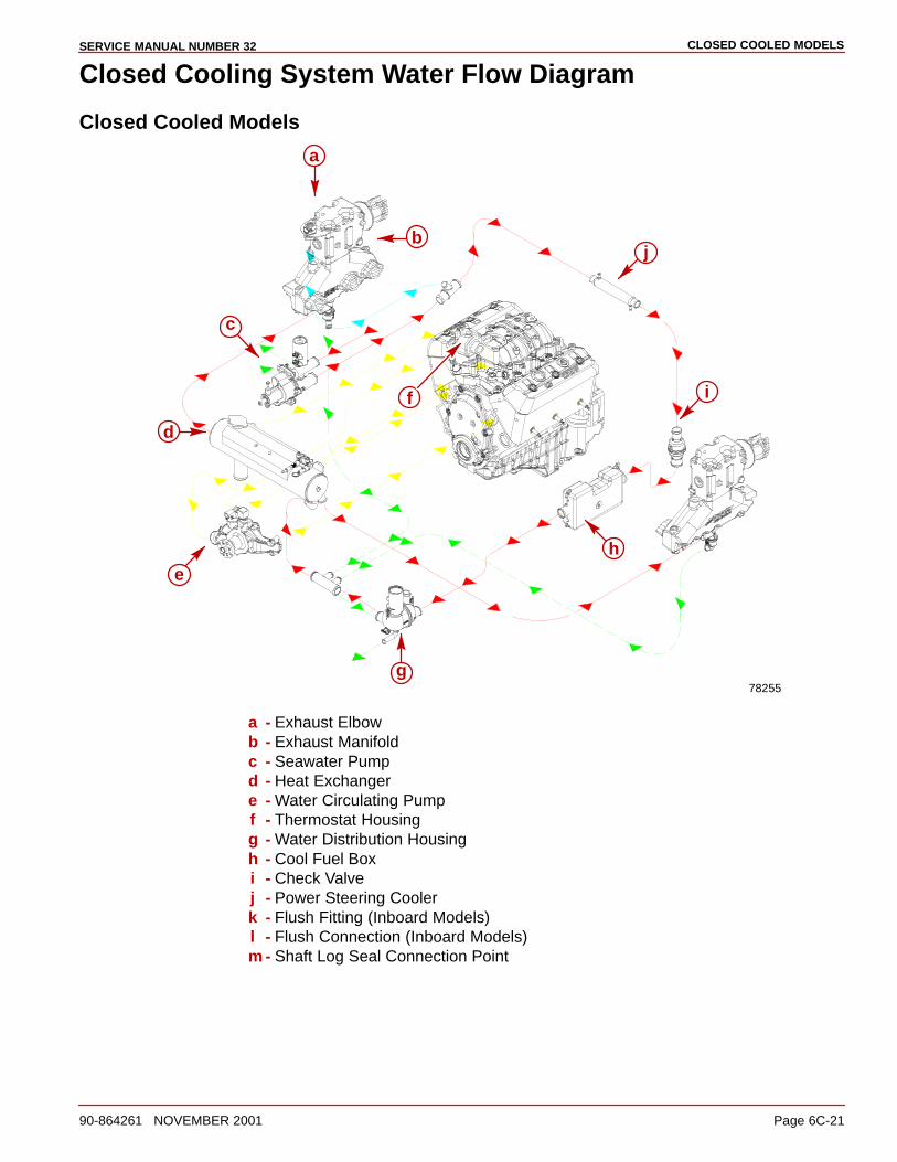
CLOSED COOLED MODELSSERVICE MANUAL NUMBER 32
90-864261 NOVEMBER 2001 Page 6C-21
Closed Cooling System Water Flow Diagram
Closed Cooled Models
78255
a
b
c
e
f
h
i
j
d
g
a - Exhaust Elbowb - Exhaust Manifoldc - Seawater Pumpd - Heat Exchangere - Water Circulating Pumpf - Thermostat Housingg - Water Distribution Housingh - Cool Fuel Boxi - Check Valvej - Power Steering Coolerk - Flush Fitting (Inboard Models)l - Flush Connection (Inboard Models)m - Shaft Log Seal Connection Point
7A
MANIFOLDS, ELBOWS AND RISERSSERVICE MANUAL NUMBER 32
90-864261 NOVEMBER 2001 Page 7A-1
EXHAUST SYSTEMSSection 7A - Manifolds, Elbows And Risers
Table of Contents
Torque Specifications 7A-2. . . . . . . . . . . . . . . . . . Lubricants / Sealants / Adhesives 7A-2. . . . . . . Exploded View 7A-3. . . . . . . . . . . . . . . . . . . . . . . . Removal 7A-5. . . . . . . . . . . . . . . . . . . . . . . . . . . . .
Cleaning and Inspection 7A-6. . . . . . . . . . . . . . . . Manifold Leak Test 7A-7. . . . . . . . . . . . . . . . . . . . Installation 7A-7. . . . . . . . . . . . . . . . . . . . . . . . . . .
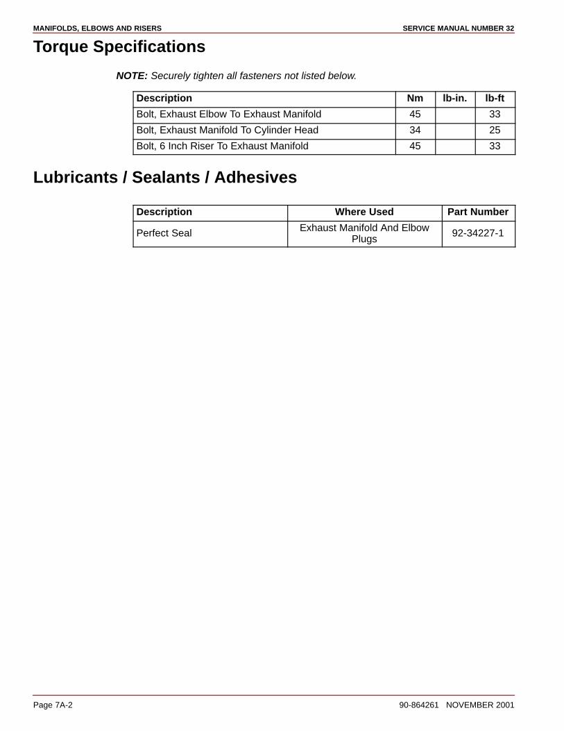
MANIFOLDS, ELBOWS AND RISERS SERVICE MANUAL NUMBER 32
Page 7A-2 90-864261 NOVEMBER 2001
Torque Specifications
NOTE: Securely tighten all fasteners not listed below.
Description Nm lb-in. lb-ft
Bolt, Exhaust Elbow To Exhaust Manifold 45 33
Bolt, Exhaust Manifold To Cylinder Head 34 25
Bolt, 6 Inch Riser To Exhaust Manifold 45 33
Lubricants / Sealants / Adhesives
Description Where Used Part Number
Perfect Seal Exhaust Manifold And ElbowPlugs
92-34227-1
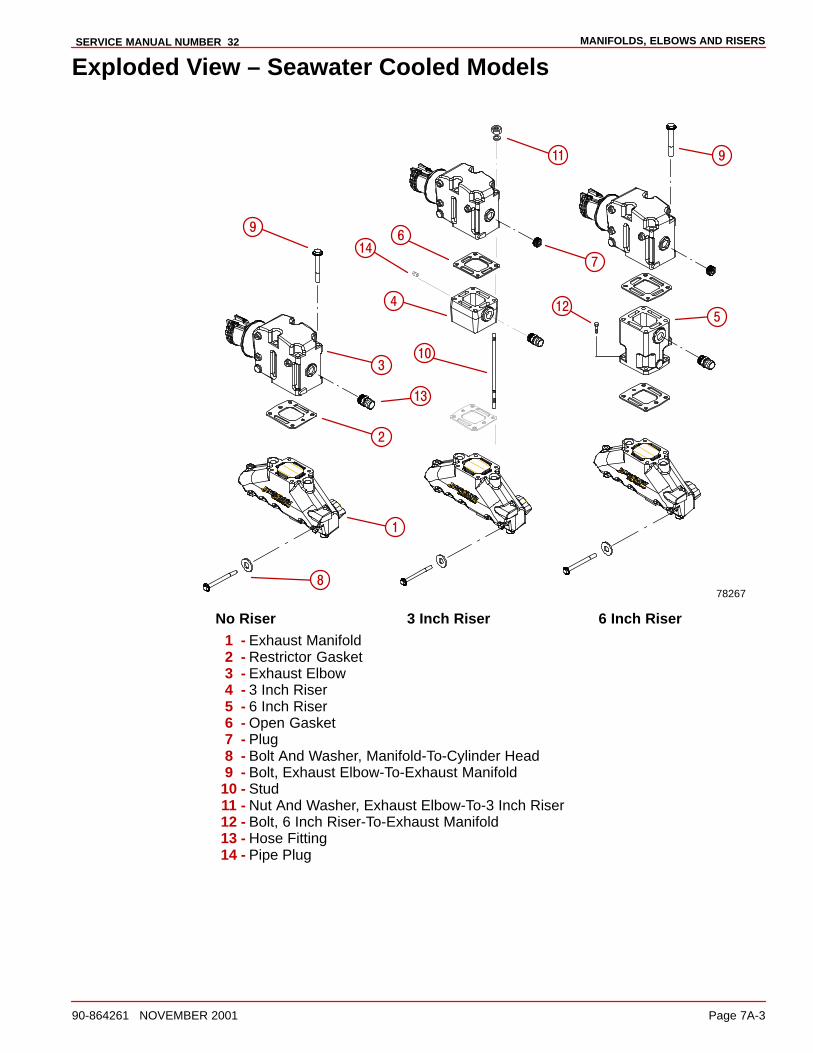
MANIFOLDS, ELBOWS AND RISERSSERVICE MANUAL NUMBER 32
90-864261 NOVEMBER 2001 Page 7A-3
Exploded View – Seawater Cooled Models
78267
Ê
ÊÊ
�
�
���
��
��
��
��
�
�
�
�
No Riser 3 Inch Riser 6 Inch Riser1 - Exhaust Manifold2 - Restrictor Gasket3 - Exhaust Elbow4 - 3 Inch Riser5 - 6 Inch Riser6 - Open Gasket7 - Plug8 - Bolt And Washer, Manifold-To-Cylinder Head9 - Bolt, Exhaust Elbow-To-Exhaust Manifold
10 - Stud11 - Nut And Washer, Exhaust Elbow-To-3 Inch Riser12 - Bolt, 6 Inch Riser-To-Exhaust Manifold13 - Hose Fitting14 - Pipe Plug
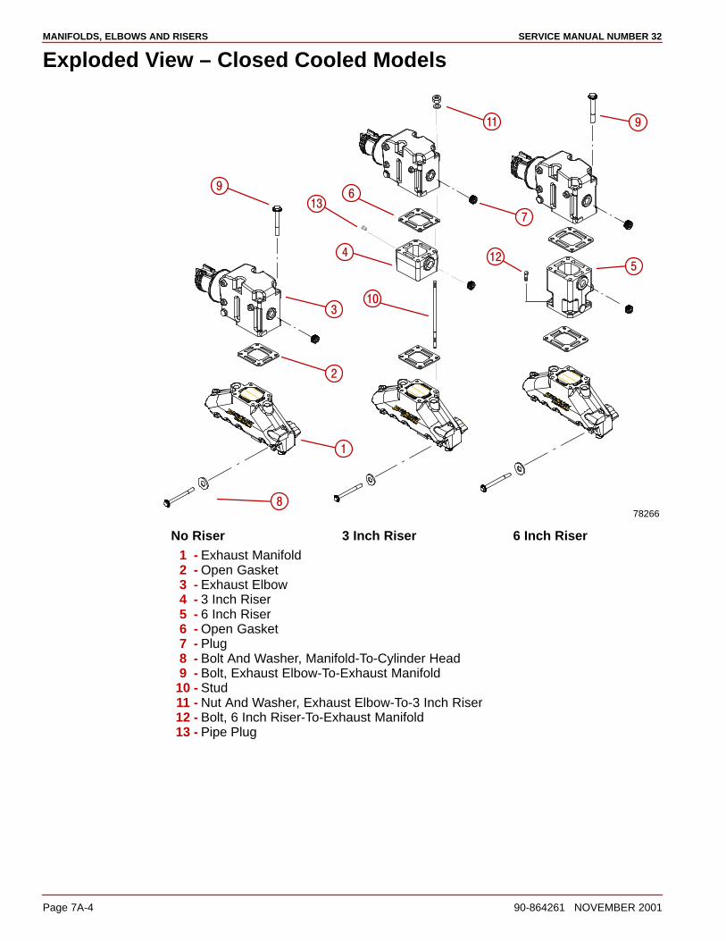
MANIFOLDS, ELBOWS AND RISERS SERVICE MANUAL NUMBER 32
Page 7A-4 90-864261 NOVEMBER 2001
Exploded View – Closed Cooled Models
78266
Ê
ÊÊ
�
�
���
��
��
��
�
�
�
�
No Riser 3 Inch Riser 6 Inch Riser1 - Exhaust Manifold2 - Open Gasket3 - Exhaust Elbow4 - 3 Inch Riser5 - 6 Inch Riser6 - Open Gasket7 - Plug8 - Bolt And Washer, Manifold-To-Cylinder Head9 - Bolt, Exhaust Elbow-To-Exhaust Manifold
10 - Stud11 - Nut And Washer, Exhaust Elbow-To-3 Inch Riser12 - Bolt, 6 Inch Riser-To-Exhaust Manifold13 - Pipe Plug
MANIFOLDS, ELBOWS AND RISERSSERVICE MANUAL NUMBER 32
90-864261 NOVEMBER 2001 Page 7A-5
Removal
WARNINGAvoid possible injury or damage to equipment should wires be accidentallyshorted. Disconnect BOTH battery cables from the battery before proceeding.
1. Disconnect both battery cables from the battery.
CAUTIONTo avoid severe engine damage, exhaust elbows and manifolds MUST BE drainedto prevent water from entering the combustion chambers when the exhaust elbowsare removed.
2. Drain the seawater section of the engine. Refer to SECTION 1B.
3. Disconnect the exhaust hoses and the cooling hoses from the exhaust manifold andelbow.
4. Remove the shift plate.
5. Remove the ECM and the ECM bracket.
6. Remove any other components that are mounted to the manifold, the elbow and theriser.
7. Remove the elbow and the riser.
8. Remove the exhaust manifold and discard the gaskets.
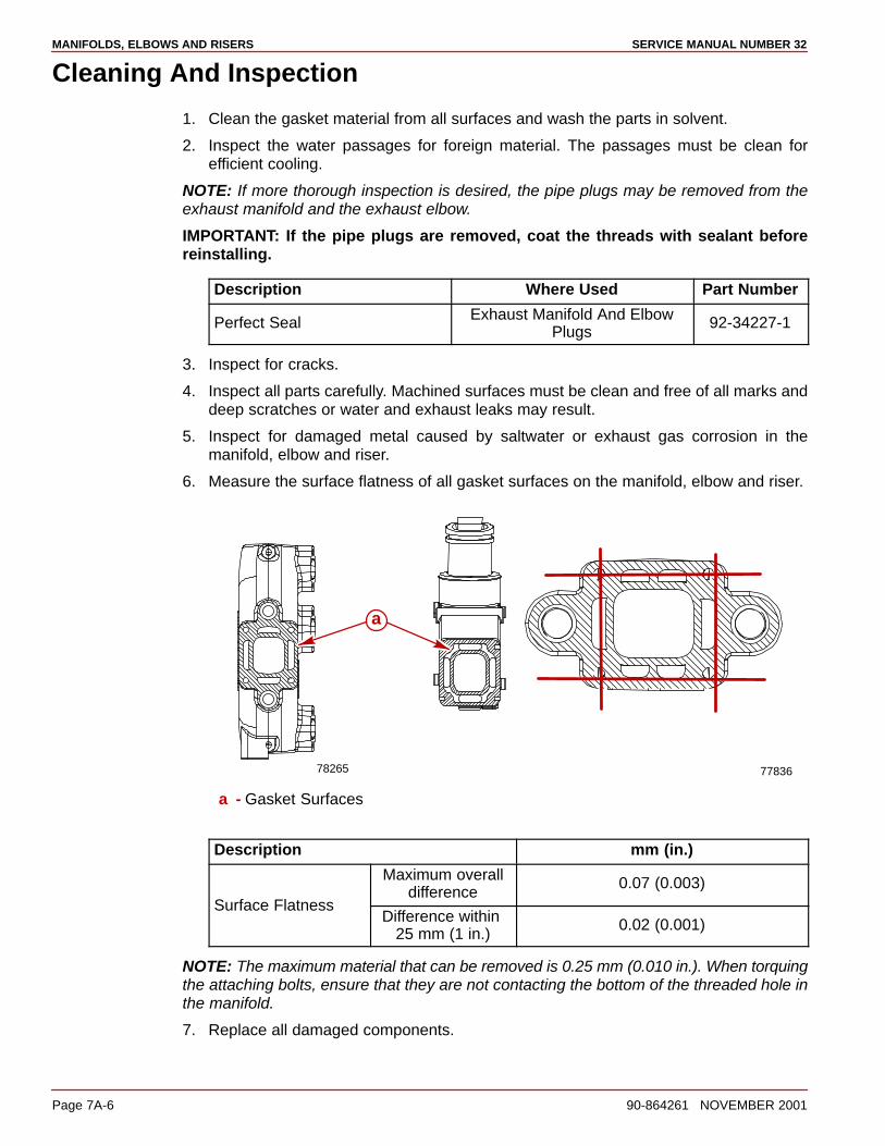
MANIFOLDS, ELBOWS AND RISERS SERVICE MANUAL NUMBER 32
Page 7A-6 90-864261 NOVEMBER 2001
Cleaning And Inspection
1. Clean the gasket material from all surfaces and wash the parts in solvent.
2. Inspect the water passages for foreign material. The passages must be clean forefficient cooling.
NOTE: If more thorough inspection is desired, the pipe plugs may be removed from theexhaust manifold and the exhaust elbow.
IMPORTANT: If the pipe plugs are removed, coat the threads with sealant beforereinstalling.
Description Where Used Part Number
Perfect Seal Exhaust Manifold And ElbowPlugs
92-34227-1
3. Inspect for cracks.
4. Inspect all parts carefully. Machined surfaces must be clean and free of all marks anddeep scratches or water and exhaust leaks may result.
5. Inspect for damaged metal caused by saltwater or exhaust gas corrosion in themanifold, elbow and riser.
6. Measure the surface flatness of all gasket surfaces on the manifold, elbow and riser.
77836
a
78265
a - Gasket Surfaces
Description mm (in.)
Maximum overalldifference
0.07 (0.003)Surface Flatness
Difference within 25 mm (1 in.)
0.02 (0.001)
NOTE: The maximum material that can be removed is 0.25 mm (0.010 in.). When torquingthe attaching bolts, ensure that they are not contacting the bottom of the threaded hole inthe manifold.
7. Replace all damaged components.
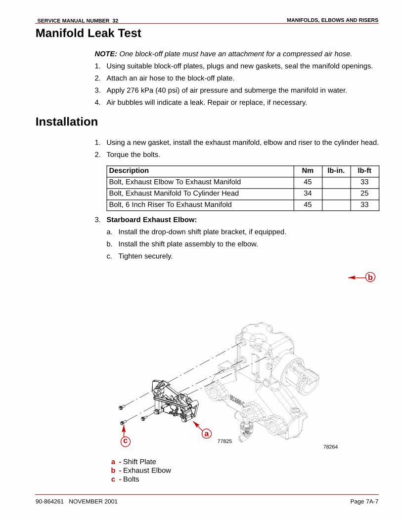
MANIFOLDS, ELBOWS AND RISERSSERVICE MANUAL NUMBER 32
90-864261 NOVEMBER 2001 Page 7A-7
Manifold Leak Test
NOTE: One block-off plate must have an attachment for a compressed air hose.
1. Using suitable block-off plates, plugs and new gaskets, seal the manifold openings.
2. Attach an air hose to the block-off plate.
3. Apply 276 kPa (40 psi) of air pressure and submerge the manifold in water.
4. Air bubbles will indicate a leak. Repair or replace, if necessary.
Installation
1. Using a new gasket, install the exhaust manifold, elbow and riser to the cylinder head.
2. Torque the bolts.
Description Nm lb-in. lb-ft
Bolt, Exhaust Elbow To Exhaust Manifold 45 33
Bolt, Exhaust Manifold To Cylinder Head 34 25
Bolt, 6 Inch Riser To Exhaust Manifold 45 33
3. Starboard Exhaust Elbow:
a. Install the drop-down shift plate bracket, if equipped.
b. Install the shift plate assembly to the elbow.
c. Tighten securely.
77825a
b
c78264
a - Shift Plateb - Exhaust Elbowc - Bolts
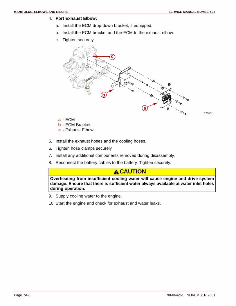
MANIFOLDS, ELBOWS AND RISERS SERVICE MANUAL NUMBER 32
Page 7A-8 90-864261 NOVEMBER 2001
4. Port Exhaust Elbow:
a. Install the ECM drop-down bracket, if equipped.
b. Install the ECM bracket and the ECM to the exhaust elbow.
c. Tighten securely.
77825
a
b
c
a - ECMb - ECM Bracketc - Exhaust Elbow
5. Install the exhaust hoses and the cooling hoses.
6. Tighten hose clamps securely.
7. Install any additional components removed during disassembly.
8. Reconnect the battery cables to the battery. Tighten securely.
CAUTIONOverheating from insufficient cooling water will cause engine and drive systemdamage. Ensure that there is sufficient water always available at water inlet holesduring operation.
9. Supply cooling water to the engine.
10. Start the engine and check for exhaust and water leaks.

8A
POWER STEERING PUMPSERVICE MANUAL NUMBER 32
90-864261 NOVEMBER 2001 Page 8A-1
POWER STEERINGSection 8A - Power Steering Pump
Table of Contents
Torque Specifications 8A-2. . . . . . . . . . . . . . . . Lubricants / Sealants / Adhesives 8A-2. . . . . Special Tools 8A-2. . . . . . . . . . . . . . . . . . . . . . . Precautions 8A-3. . . . . . . . . . . . . . . . . . . . . . . . Power Steering Pump And ComponentsExploded View 8A-4. . . . . . . . . . . . . . . . . . . . . . Power Steering Pump Pulley Replacement 8A-5. . . . . . . . . . . . . . . . .
Removal 8A-5. . . . . . . . . . . . . . . . . . . . . . . . . Installation 8A-5. . . . . . . . . . . . . . . . . . . . . . .
Power Steering Pump 8A-6. . . . . . . . . . . . . . . . Removal 8A-6. . . . . . . . . . . . . . . . . . . . . . . . . Flow Control Valve Servicing 8A-7. . . . . . . Pump Shaft Oil Seal Replacement 8A-8. . Installation 8A-10. . . . . . . . . . . . . . . . . . . . . . .
Replacing Belt And/Or Adjusting Tension 8A-11Filling And Bleeding 8A-11. . . . . . . . . . . . . . . . . Checking Fluid Level 8A-11. . . . . . . . . . . . . . . . . Hydraulic Hoses And Fluid Cooler 8A-12. . . . .
High Pressure Hose (Pump-To-Control Valve) 8A-12. . . . . . . . . . Low Pressure Hose (Pump-To-Fluid Cooler) 8A-14. . . . . . . . . . . Low Pressure Hose (Control Valve-To-Fluid Cooler) 8A-16. . . .
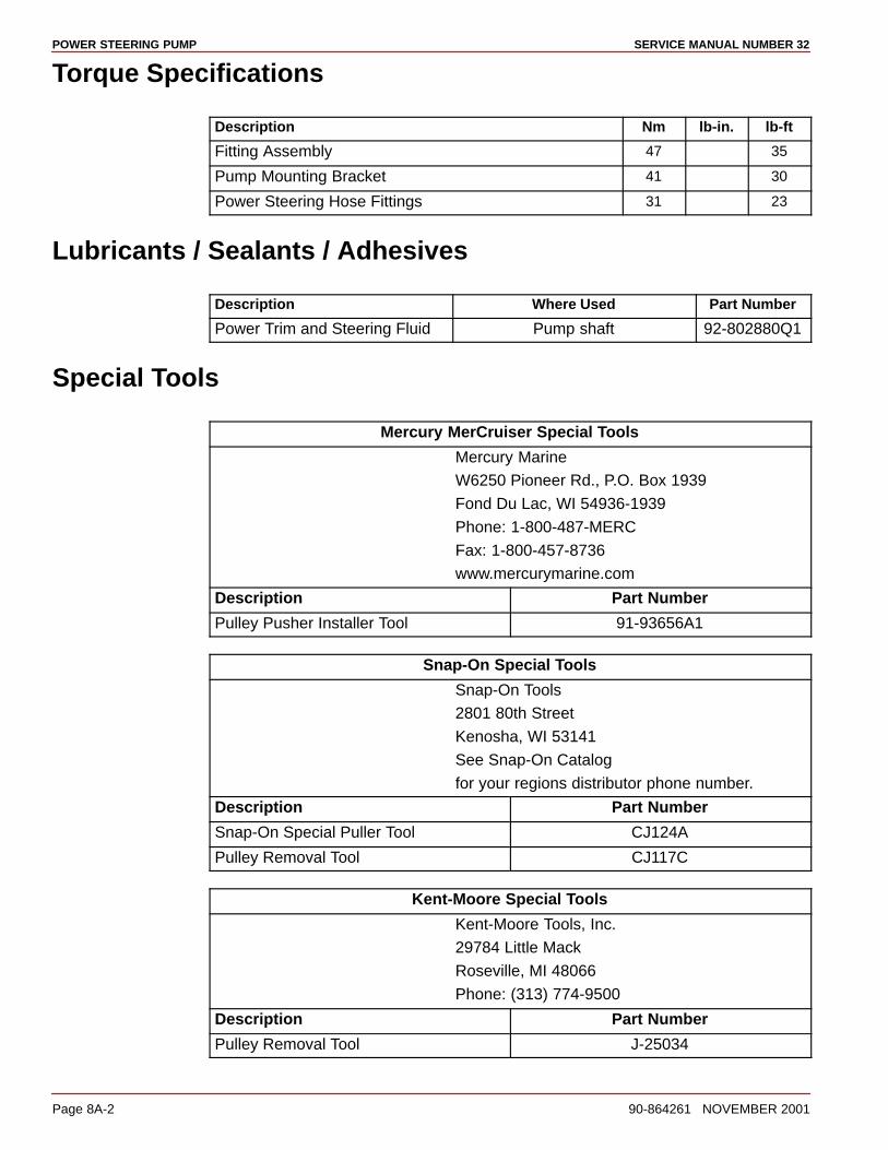
POWER STEERING PUMP SERVICE MANUAL NUMBER 32
Page 8A-2 90-864261 NOVEMBER 2001
Torque Specifications
Description Nm lb-in. lb-ft
Fitting Assembly 47 35
Pump Mounting Bracket 41 30
Power Steering Hose Fittings 31 23
Lubricants / Sealants / Adhesives
Description Where Used Part Number
Power Trim and Steering Fluid Pump shaft 92-802880Q1
Special Tools
Mercury MerCruiser Special Tools
Mercury Marine
W6250 Pioneer Rd., P.O. Box 1939
Fond Du Lac, WI 54936-1939
Phone: 1-800-487-MERC
Fax: 1-800-457-8736
www.mercurymarine.com
Description Part Number
Pulley Pusher Installer Tool 91-93656A1
Snap-On Special Tools
Snap-On Tools
2801 80th Street
Kenosha, WI 53141
See Snap-On Catalog
for your regions distributor phone number.
Description Part Number
Snap-On Special Puller Tool CJ124A
Pulley Removal Tool CJ117C
Kent-Moore Special Tools
Kent-Moore Tools, Inc.
29784 Little Mack
Roseville, MI 48066
Phone: (313) 774-9500
Description Part Number
Pulley Removal Tool J-25034
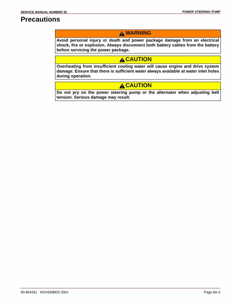
POWER STEERING PUMPSERVICE MANUAL NUMBER 32
90-864261 NOVEMBER 2001 Page 8A-3
Precautions
WARNINGAvoid personal injury or death and power package damage from an electricalshock, fire or explosion. Always disconnect both battery cables from the batterybefore servicing the power package.
CAUTIONOverheating from insufficient cooling water will cause engine and drive systemdamage. Ensure that there is sufficient water always available at water inlet holesduring operation.
CAUTIONDo not pry on the power steering pump or the alternator when adjusting belttension. Serious damage may result.
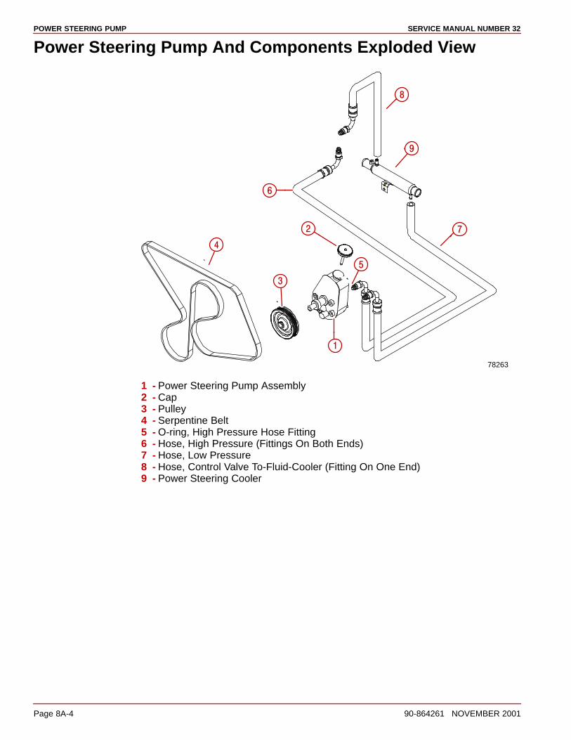
POWER STEERING PUMP SERVICE MANUAL NUMBER 32
Page 8A-4 90-864261 NOVEMBER 2001
Power Steering Pump And Components Exploded View
78263
�
�
�
�
�
�
�
�
1 - Power Steering Pump Assembly2 - Cap3 - Pulley4 - Serpentine Belt5 - O-ring, High Pressure Hose Fitting6 - Hose, High Pressure (Fittings On Both Ends)7 - Hose, Low Pressure8 - Hose, Control Valve To-Fluid-Cooler (Fitting On One End)9 - Power Steering Cooler
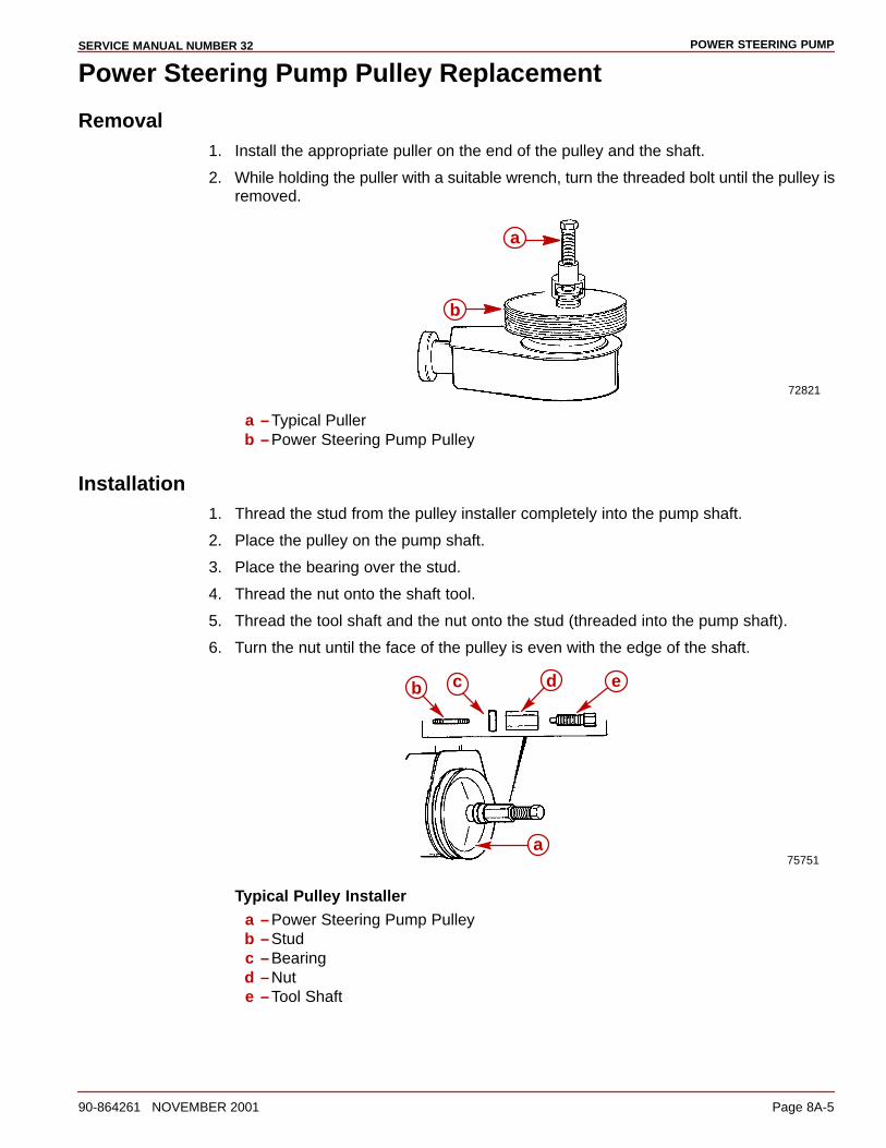
POWER STEERING PUMPSERVICE MANUAL NUMBER 32
90-864261 NOVEMBER 2001 Page 8A-5
Power Steering Pump Pulley Replacement
Removal1. Install the appropriate puller on the end of the pulley and the shaft.
2. While holding the puller with a suitable wrench, turn the threaded bolt until the pulley isremoved.
72821
b
a
a –Typical Pullerb –Power Steering Pump Pulley
Installation1. Thread the stud from the pulley installer completely into the pump shaft.
2. Place the pulley on the pump shaft.
3. Place the bearing over the stud.
4. Thread the nut onto the shaft tool.
5. Thread the tool shaft and the nut onto the stud (threaded into the pump shaft).
6. Turn the nut until the face of the pulley is even with the edge of the shaft.
75751
b
a
ec d
Typical Pulley Installera –Power Steering Pump Pulleyb –Studc –Bearingd –Nute –Tool Shaft
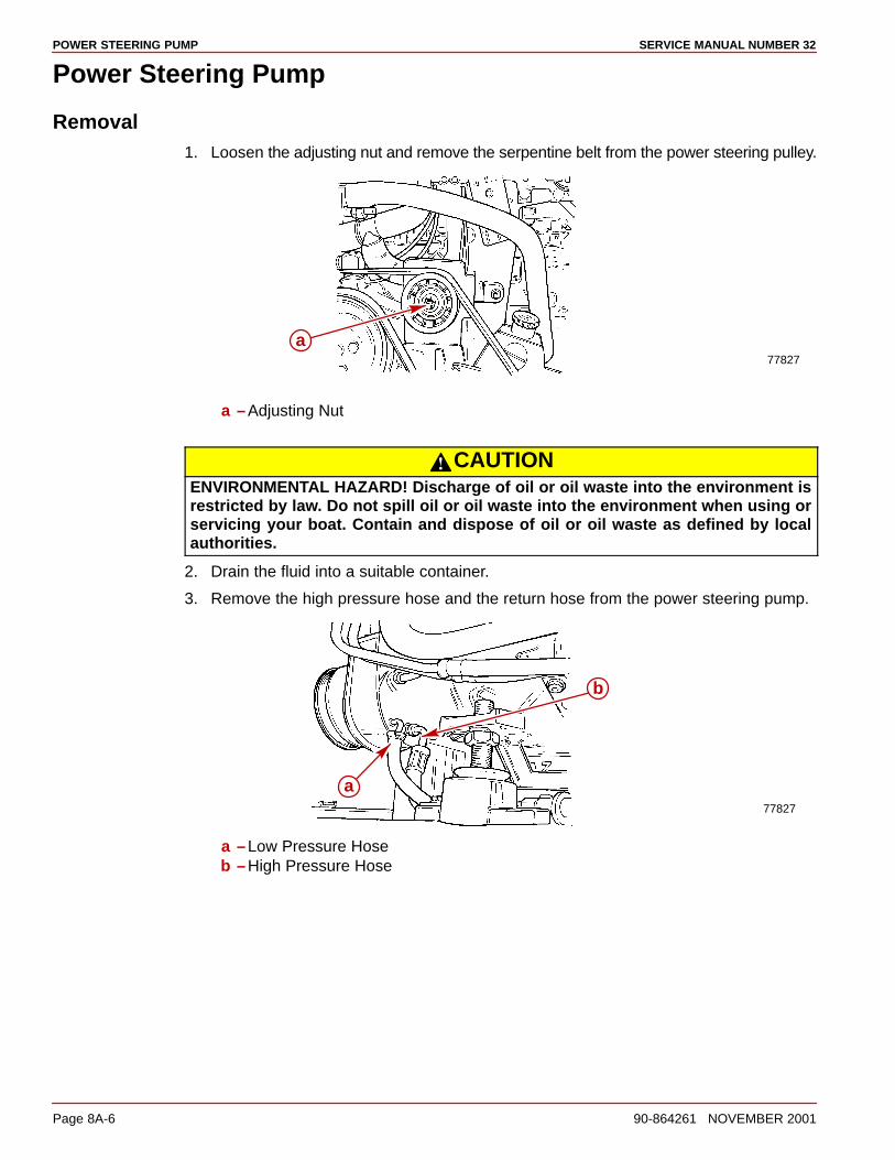
POWER STEERING PUMP SERVICE MANUAL NUMBER 32
Page 8A-6 90-864261 NOVEMBER 2001
Power Steering Pump
Removal1. Loosen the adjusting nut and remove the serpentine belt from the power steering pulley.
77827
a
a –Adjusting Nut
CAUTIONENVIRONMENTAL HAZARD! Discharge of oil or oil waste into the environment isrestricted by law. Do not spill oil or oil waste into the environment when using orservicing your boat. Contain and dispose of oil or oil waste as defined by localauthorities.
2. Drain the fluid into a suitable container.
3. Remove the high pressure hose and the return hose from the power steering pump.
77827
a
b
a –Low Pressure Hoseb –High Pressure Hose

POWER STEERING PUMPSERVICE MANUAL NUMBER 32
90-864261 NOVEMBER 2001 Page 8A-7
4. Remove the mounting fasteners from the pump.
77829 77830
b
a
a –Nutb –Bolts
5. Remove the front bracket from the pump.
6. Remove the power steering pump from the bracket.
Flow Control Valve Servicing1. Drain the fluid from the pump.
2. Remove the high pressure fitting assembly.
a b cd d
76869
a –High Pressure Fittingb –Control Valve Assemblyc –Flow Control Springd –O-rings
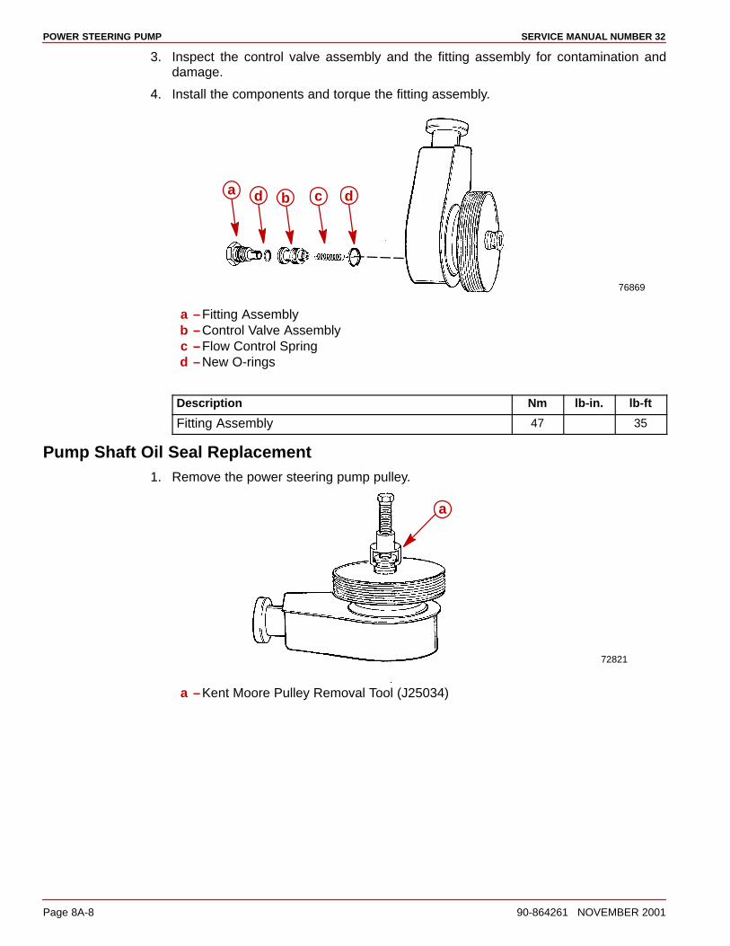
POWER STEERING PUMP SERVICE MANUAL NUMBER 32
Page 8A-8 90-864261 NOVEMBER 2001
3. Inspect the control valve assembly and the fitting assembly for contamination anddamage.
4. Install the components and torque the fitting assembly.
a b cd d
76869
a –Fitting Assemblyb –Control Valve Assemblyc –Flow Control Springd –New O-rings
Description Nm lb-in. lb-ft
Fitting Assembly 47 35
Pump Shaft Oil Seal Replacement1. Remove the power steering pump pulley.
a
72821
a –Kent Moore Pulley Removal Tool (J25034)
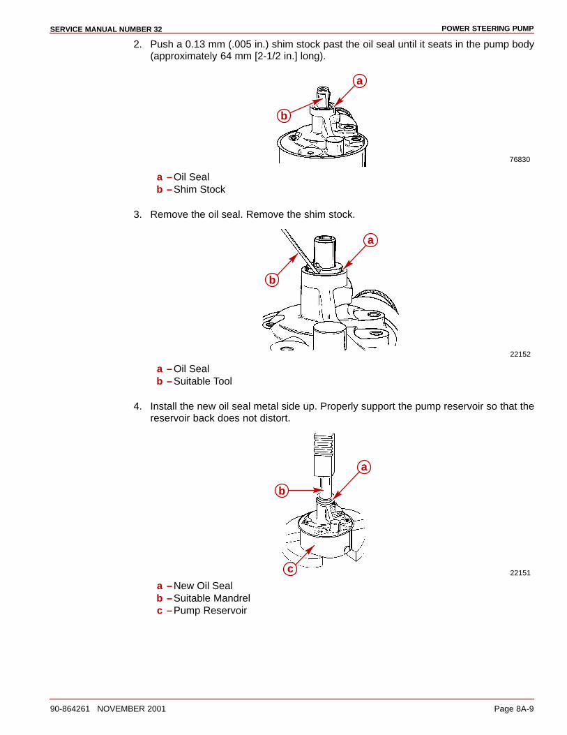
POWER STEERING PUMPSERVICE MANUAL NUMBER 32
90-864261 NOVEMBER 2001 Page 8A-9
2. Push a 0.13 mm (.005 in.) shim stock past the oil seal until it seats in the pump body(approximately 64 mm [2-1/2 in.] long).
76830
a
b
a –Oil Sealb –Shim Stock
3. Remove the oil seal. Remove the shim stock.
22152
b
a
a –Oil Sealb –Suitable Tool
4. Install the new oil seal metal side up. Properly support the pump reservoir so that thereservoir back does not distort.
22151
b
a
c
a –New Oil Sealb –Suitable Mandrelc –Pump Reservoir
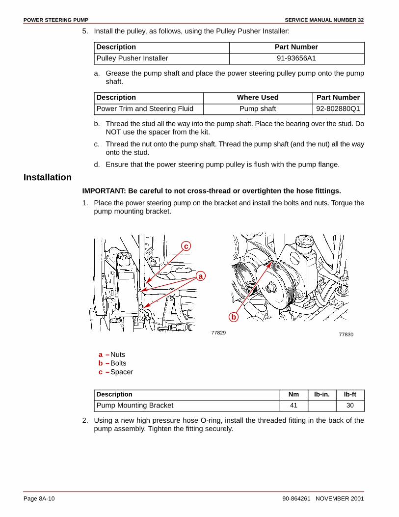
POWER STEERING PUMP SERVICE MANUAL NUMBER 32
Page 8A-10 90-864261 NOVEMBER 2001
5. Install the pulley, as follows, using the Pulley Pusher Installer:
Description Part Number
Pulley Pusher Installer 91-93656A1
a. Grease the pump shaft and place the power steering pulley pump onto the pumpshaft.
Description Where Used Part Number
Power Trim and Steering Fluid Pump shaft 92-802880Q1
b. Thread the stud all the way into the pump shaft. Place the bearing over the stud. DoNOT use the spacer from the kit.
c. Thread the nut onto the pump shaft. Thread the pump shaft (and the nut) all the wayonto the stud.
d. Ensure that the power steering pump pulley is flush with the pump flange.
InstallationIMPORTANT: Be careful to not cross-thread or overtighten the hose fittings.
1. Place the power steering pump on the bracket and install the bolts and nuts. Torque thepump mounting bracket.
77829 77830
a
b
c
a –Nutsb –Boltsc –Spacer
Description Nm lb-in. lb-ft
Pump Mounting Bracket 41 30
2. Using a new high pressure hose O-ring, install the threaded fitting in the back of thepump assembly. Tighten the fitting securely.
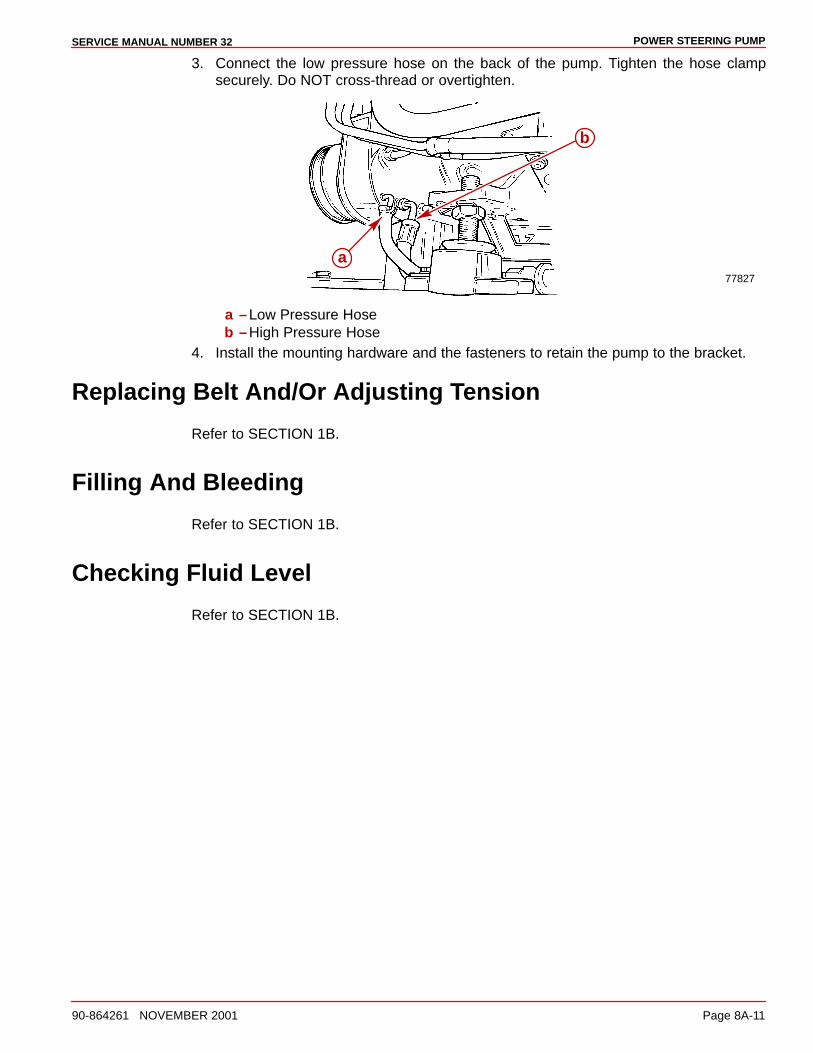
POWER STEERING PUMPSERVICE MANUAL NUMBER 32
90-864261 NOVEMBER 2001 Page 8A-11
3. Connect the low pressure hose on the back of the pump. Tighten the hose clampsecurely. Do NOT cross-thread or overtighten.
77827
a
b
a –Low Pressure Hoseb –High Pressure Hose
4. Install the mounting hardware and the fasteners to retain the pump to the bracket.
Replacing Belt And/Or Adjusting Tension
Refer to SECTION 1B.
Filling And Bleeding
Refer to SECTION 1B.
Checking Fluid Level
Refer to SECTION 1B.
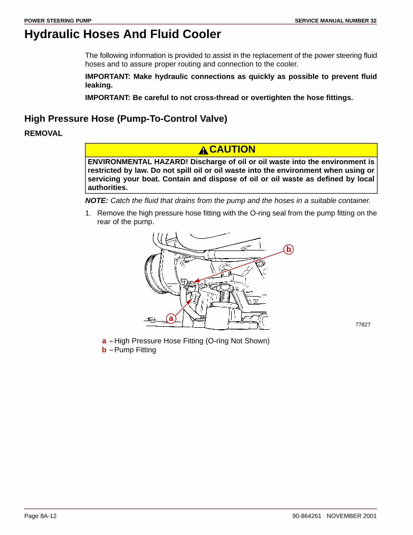
POWER STEERING PUMP SERVICE MANUAL NUMBER 32
Page 8A-12 90-864261 NOVEMBER 2001
Hydraulic Hoses And Fluid Cooler
The following information is provided to assist in the replacement of the power steering fluidhoses and to assure proper routing and connection to the cooler.
IMPORTANT: Make hydraulic connections as quickly as possible to prevent fluidleaking.
IMPORTANT: Be careful to not cross-thread or overtighten the hose fittings.
High Pressure Hose (Pump-To-Control Valve)
REMOVAL
CAUTIONENVIRONMENTAL HAZARD! Discharge of oil or oil waste into the environment isrestricted by law. Do not spill oil or oil waste into the environment when using orservicing your boat. Contain and dispose of oil or oil waste as defined by localauthorities.
NOTE: Catch the fluid that drains from the pump and the hoses in a suitable container.
1. Remove the high pressure hose fitting with the O-ring seal from the pump fitting on therear of the pump.
77827a
b
a –High Pressure Hose Fitting (O-ring Not Shown)b –Pump Fitting

POWER STEERING PUMPSERVICE MANUAL NUMBER 32
90-864261 NOVEMBER 2001 Page 8A-13
2. Remove the hose where routed and secured (port or starboard side), across the top ofthe engine, near the valve cover.
3. Remove the fitting from the control valve at the transom. Remove the hose.
77845
a
a –Power Steering Hose FittingINSTALLATION
CAUTIONRoute the hoses exactly as shown below. This will help avoid stress on the hosefittings and will help avoid kinks in the hoses.
IMPORTANT: Be careful to not cross-thread or overtighten the hose fittings.
1. Route the hose in the same position as prior to removal. Install the power steering hosefitting and torque. Do NOT cross-thread or overtighten.
77845a
a –Power Steering Hose Fitting
Description Nm lb-in. lb-ft
Power Steering Hose Fitting 31 23
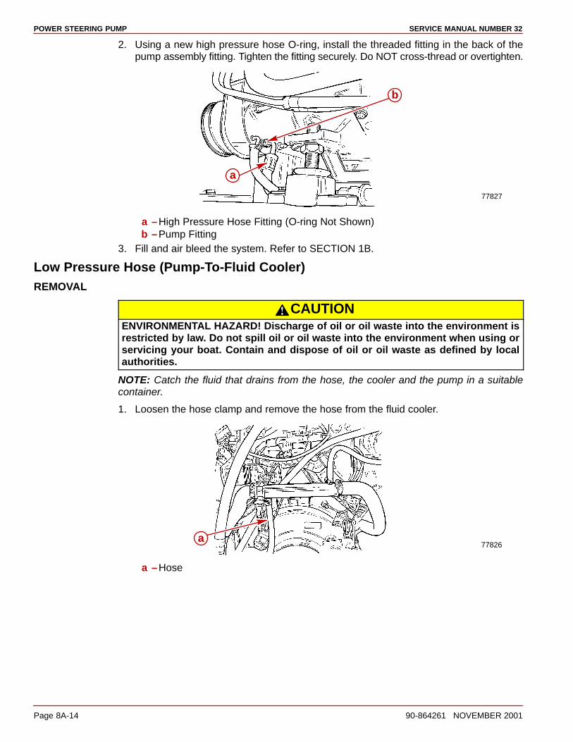
POWER STEERING PUMP SERVICE MANUAL NUMBER 32
Page 8A-14 90-864261 NOVEMBER 2001
2. Using a new high pressure hose O-ring, install the threaded fitting in the back of thepump assembly fitting. Tighten the fitting securely. Do NOT cross-thread or overtighten.
77827
a
b
a –High Pressure Hose Fitting (O-ring Not Shown)b –Pump Fitting
3. Fill and air bleed the system. Refer to SECTION 1B.
Low Pressure Hose (Pump-To-Fluid Cooler)REMOVAL
CAUTIONENVIRONMENTAL HAZARD! Discharge of oil or oil waste into the environment isrestricted by law. Do not spill oil or oil waste into the environment when using orservicing your boat. Contain and dispose of oil or oil waste as defined by localauthorities.
NOTE: Catch the fluid that drains from the hose, the cooler and the pump in a suitablecontainer.
1. Loosen the hose clamp and remove the hose from the fluid cooler.
77826a
a –Hose
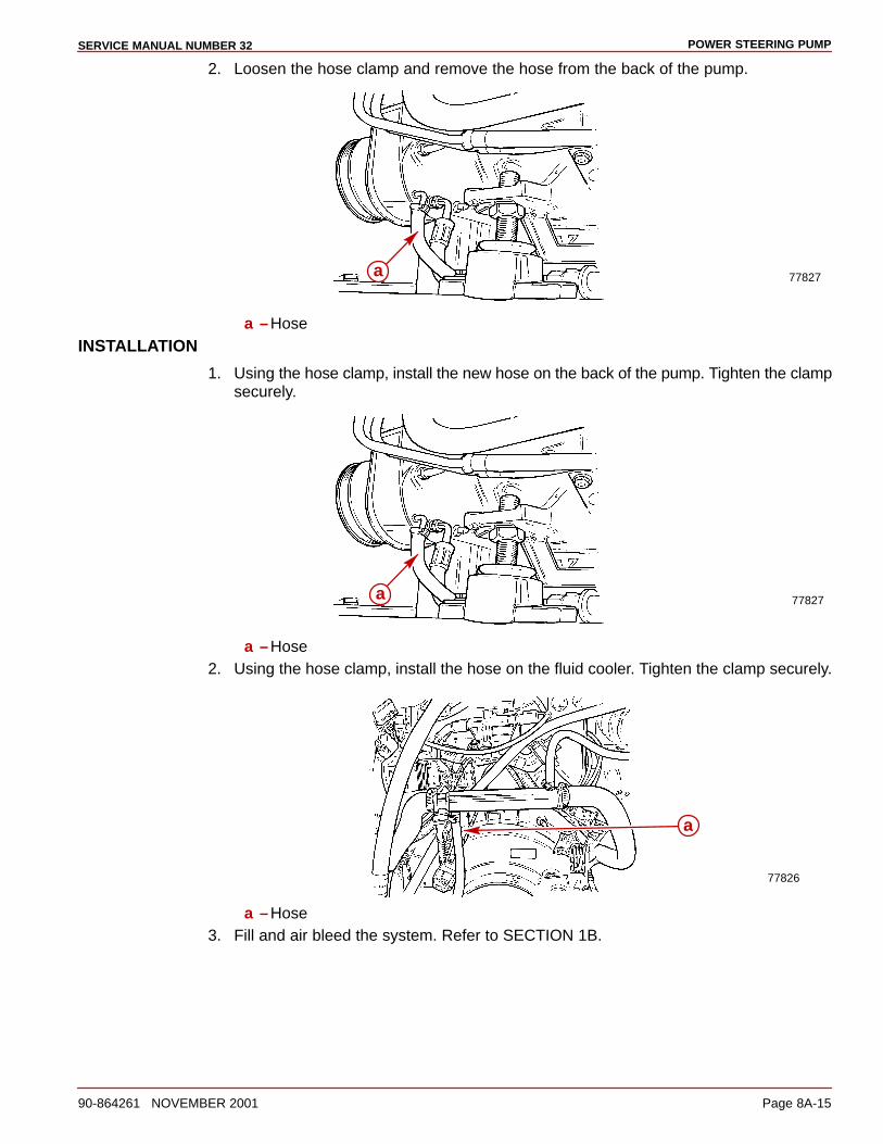
POWER STEERING PUMPSERVICE MANUAL NUMBER 32
90-864261 NOVEMBER 2001 Page 8A-15
2. Loosen the hose clamp and remove the hose from the back of the pump.
77827a
a –HoseINSTALLATION
1. Using the hose clamp, install the new hose on the back of the pump. Tighten the clampsecurely.
77827a
a –Hose2. Using the hose clamp, install the hose on the fluid cooler. Tighten the clamp securely.
77826
a
a –Hose3. Fill and air bleed the system. Refer to SECTION 1B.

POWER STEERING PUMP SERVICE MANUAL NUMBER 32
Page 8A-16 90-864261 NOVEMBER 2001
Low Pressure Hose (Control Valve-To-Fluid Cooler)
REMOVAL
CAUTIONENVIRONMENTAL HAZARD! Discharge of oil or oil waste into the environment isrestricted by law. Do not spill oil or oil waste into the environment when using orservicing your boat. Contain and dispose of oil or oil waste as defined by localauthorities.
NOTE: Catch the fluid that drains from the hose, the cooler and the pump in a suitablecontainer.
1. Loosen the hose clamp and remove the hose from the fluid cooler.
a
77826
a –Hose2. Remove the fitting from the control valve at the transom. Remove the hose.
77845a
a –Power Steering Hose Fitting
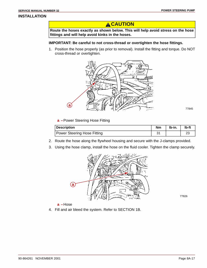
POWER STEERING PUMPSERVICE MANUAL NUMBER 32
90-864261 NOVEMBER 2001 Page 8A-17
INSTALLATION
CAUTIONRoute the hoses exactly as shown below. This will help avoid stress on the hosefittings and will help avoid kinks in the hoses.
IMPORTANT: Be careful to not cross-thread or overtighten the hose fittings.
1. Position the hose properly (as prior to removal). Install the fitting and torque. Do NOTcross-thread or overtighten.
77845a
a –Power Steering Hose Fitting
Description Nm lb-in. lb-ft
Power Steering Hose Fitting 31 23
2. Route the hose along the flywheel housing and secure with the J-clamps provided.
3. Using the hose clamp, install the hose on the fluid cooler. Tighten the clamp securely.
a
77826
a –Hose4. Fill and air bleed the system. Refer to SECTION 1B.