combined security camera led floodlight system security camera led floodlight system guardcam led...
TRANSCRIPT
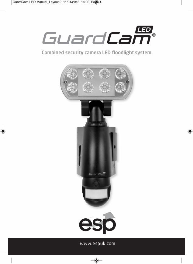
Combined security camera LED floodlight system
GuardCam LED Manual_Layout 2 11/04/2013 14:02 Page 1

2
The requirement to install back up batteries has now been removed from thelatest version of GuardCam. Time and date settings will now be maintainedduring mains power outages for a minimum of 72 hours.
The minimum requirements of a PC / Laptop required to provide accuratereading and re-writing of an SD card used within the GuardCam is as follows:
CPU Minimum 1GBRAM Minimum 2GBOS Windows 2000 / XP / Vista / 7 SD card Must have a capacity of 2GB or higher (maximum 32GB)
Formatting the SD card� It is good practice to Format the SD card using the PC / Laptop you intend
to use for viewing captured images each time any of the following eventsoccur
� After a mains power removal from the GuardCam� When changing the selected image capture option from Video to photo� When changing the selected image capture option from photo to video� After removing the SD card for viewing prior to replacing in the GuardCam
To format the SD cardPlease ensure to save any required images to an alternative folder priorto formatting.� Place it in the SD / USB adaptor supplied � Place the adaptor in a spare USB port on your PC / Laptop � Right click on the SD card location � Select Format � Ensure the correct file system is selected FAT16 ( or FAT ) for SD and
FAT32 for SDHC� Ensure the Quick Format option is NOT selected� Select "Start"Following these simple points will ensure correct operation of GuardCam andshould be considered as part of its maintenance schedule.
IMPORTANT NOTES - PLEASE READ
GuardCam LED Manual_Layout 2 11/04/2013 14:02 Page 2

Table of contentsContents of package . . . . . . . . . . . . . . . . . . . . . . . . . . . . . . . . . . . . . . . . . . . . . . . . 3GuardCam LED Motion Light with Video Camera . . . . . . . . . . . . . . . . . . . . . . . 4Step 1 - Insert/remove SD Card . . . . . . . . . . . . . . . . . . . . . . . . . . . . . . . . . . . . . . 4Step 2 - Installing the GuardCam LED . . . . . . . . . . . . . . . . . . . . . . . . . . . . . . . . . 5Step 3 - Mounting the GuardCam LED . . . . . . . . . . . . . . . . . . . . . . . . . . . . . . . . 6Step 4 - Adjusting the settings . . . . . . . . . . . . . . . . . . . . . . . . . . . . . . . . . . . . . . 7Step 5 - Setting the Date and Time and Video Mode . . . . . . . . . . . . . . . . . . . 9Step 6 - Viewing Video . . . . . . . . . . . . . . . . . . . . . . . . . . . . . . . . . . . . . . . . . . . . 10Technical Specifications . . . . . . . . . . . . . . . . . . . . . . . . . . . . . . . . . . . . . . . . . . . 11General Information and Safety . . . . . . . . . . . . . . . . . . . . . . . . . . . . . . . . . . . . . 12
Contents of package
GuardCam LED MotionLight with Video Camera
1 x Allen key2 x screws
2 x plastic masonry plugs
SD USB card reader
2G SD card and
3
User Manual
GuardCam LED Manual_Layout 2 11/04/2013 14:02 Page 3
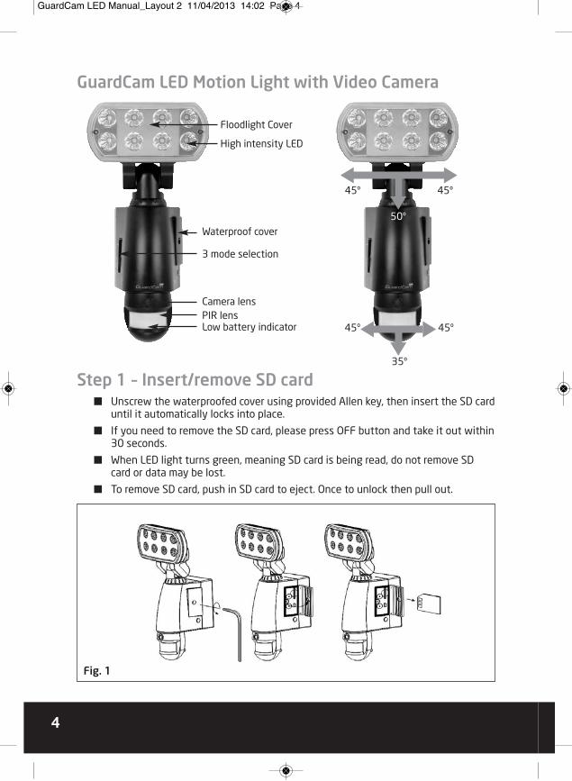
GuardCam LED Motion Light with Video Camera
Step 1 – Insert/remove SD card� Unscrew the waterproofed cover using provided Allen key, then insert the SD card
until it automatically locks into place.
� If you need to remove the SD card, please press OFF button and take it out within30 seconds.
� When LED light turns green, meaning SD card is being read, do not remove SDcard or data may be lost.
� To remove SD card, push in SD card to eject. Once to unlock then pull out.
High intensity LED
45º
45º
35º
45º
45º
50ºWaterproof cover
3 mode selection
Camera lensPIR lensLow battery indicator
Floodlight Cover
Fig. 1
4
GuardCam LED Manual_Layout 2 11/04/2013 14:02 Page 4

Step 2 - Installing the GuardCam LED
IMPORTANT - IF IN ANY DOUBT ABOUT THE INSTALLATION OF THIS PRODUCT,CONSULT A QUALIFIED ELECTRICIAN� This product must be earthed� Do not mount the unit against inflammable surfaces� The motion detector will not operate correctly if it is installed:
- Near the outlet of a central heating boiler - Near air conditioning plant - Pointing directly at moving vehicles - Within sight of reflections from moving water - Where other lamps could shine on the detector
BEFORE ATTEMPTING ANY INSTALLATION OR MAINTENANCE, ENSURE THAT THEELECTRICAL SUPPLY IS SWITCHED OFF AND THE CIRCUIT FUSES REMOVED OR THECIRCUIT BREAKER IS IN THE OFF POSITION.
Please make sure the voltage and polarity are correct before connection. Incorrectvoltage may cause electric shock. If you are not sure, please contact your retailer.
Note: It is recommend to mount GuardCam LED 2M above the ground foroptimum performance, do not mount the fixture below 1.2M. See Fig. 2 for details of performance range.
5
Detection range: 12M x 160° (see Fig. 2)
2m
2m
4m 6m 8m 10m 12m
12m
Fig. 2
GuardCam LED Manual_Layout 2 11/04/2013 14:02 Page 5

Fig. 5
Fig. 3
Fig. 4
Step 3 - Mounting your GuardCam LED1. 1. Place plastic masonry plugs into
desired surface aligning holes asshown below. Using an electricscrewdriver, fasten mounting platedirectly to surface using screws E.
2. Feed the cable through the backmounting box and bush the cableentry to avoid abrasion to the cable.
3. Wire the unit as follows: (Ensure allwires are connected securely andthat no loose strands are exposed)
4. Make sure the polarity is correct.Double check the connections afterwiring. Errors may damage themotion sensor or cause a fire hazard.
5. Attach the unit to the mountingplate. You will first need to anglethe unit back so that the catch atthe top of the mounting plate fitsinto slot on the back of the unit.Next lower the unit until holes atthe bottom of the mounting plateand unit are flush. Then screw(screw A) into this hole, tightening carefully.
Please allow 1 minute warm-up timeafter switching on.� Push the RESET button after
switching on.Remove plastic lens cover fromcamera after installation. (see Fig. 5)
6
INCOMING SUPPLY
EARTH (Green & Yellow) EARTH (Green & Yellow)
NEUTRAL (Blue or Black)
LIVE (Brown or Red)
NEUTRAL (Blue or Black)
LIVE (Brown or Red)
TO FITTING
GuardCam LED Manual_Layout 2 11/04/2013 14:02 Page 6
7
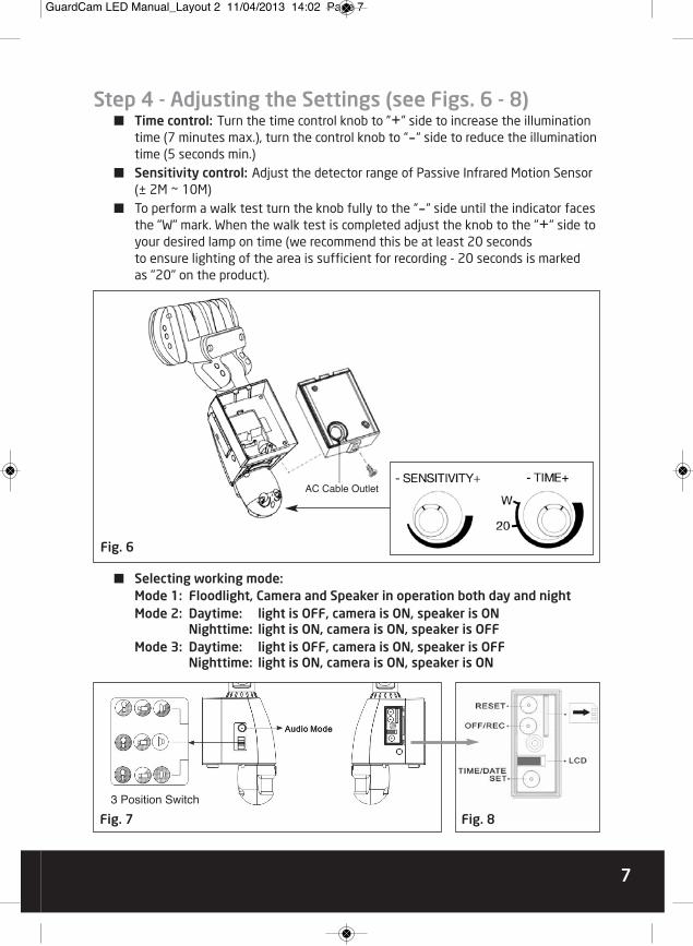
Fig. 7 Fig. 8
3 Position Switch
Step 4 - Adjusting the Settings (see Figs. 6 - 8)� Time control: Turn the time control knob to ”+” side to increase the illumination
time (7 minutes max.), turn the control knob to “-“ side to reduce the illuminationtime (5 seconds min.)
� Sensitivity control: Adjust the detector range of Passive Infrared Motion Sensor(± 2M ~ 10M)
� To perform a walk test turn the knob fully to the “-“ side until the indicator facesthe "W" mark. When the walk test is completed adjust the knob to the "+" side toyour desired lamp on time (we recommend this be at least 20 seconds to ensure lighting of the area is sufficient for recording - 20 seconds is marked as "20" on the product).
� Selecting working mode:Mode 1: Floodlight, Camera and Speaker in operation both day and nightMode 2: Daytime: light is OFF, camera is ON, speaker is ON
Nighttime: light is ON, camera is ON, speaker is OFFMode 3: Daytime: light is OFF, camera is ON, speaker is OFF
Nighttime: light is ON, camera is ON, speaker is ON
Fig. 6
AC Cable Outlet
GuardCam LED Manual_Layout 2 11/04/2013 14:02 Page 7
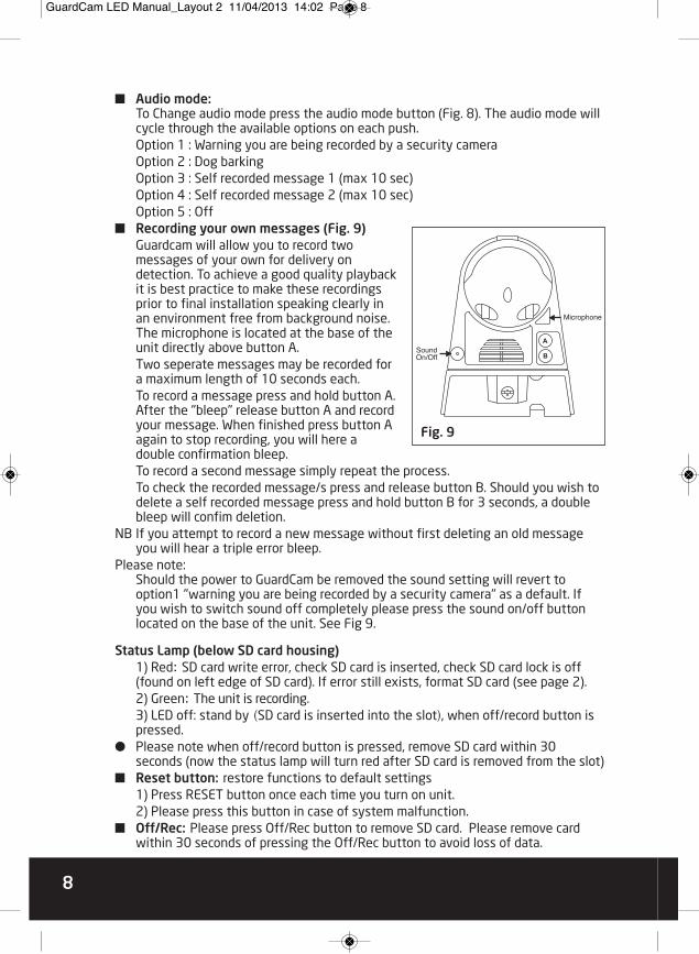
� Audio mode:To Change audio mode press the audio mode button (Fig. 8). The audio mode willcycle through the available options on each push.Option 1 : Warning you are being recorded by a security camera Option 2 : Dog barkingOption 3 : Self recorded message 1 (max 10 sec)Option 4 : Self recorded message 2 (max 10 sec)Option 5 : Off
� Recording your own messages (Fig. 9)Guardcam will allow you to record twomessages of your own for delivery ondetection. To achieve a good quality playbackit is best practice to make these recordingsprior to final installation speaking clearly inan environment free from background noise.The microphone is located at the base of theunit directly above button A.Two seperate messages may be recorded fora maximum length of 10 seconds each.To record a message press and hold button A.After the "bleep" release button A and recordyour message. When finished press button Aagain to stop recording, you will here adouble confirmation bleep. To record a second message simply repeat the process.To check the recorded message/s press and release button B. Should you wish todelete a self recorded message press and hold button B for 3 seconds, a doublebleep will confim deletion.
NB If you attempt to record a new message without first deleting an old messageyou will hear a triple error bleep.
Please note:Should the power to GuardCam be removed the sound setting will revert tooption1 "warning you are being recorded by a security camera" as a default. Ifyou wish to switch sound off completely please press the sound on/off buttonlocated on the base of the unit. See Fig 9.
Status Lamp (below SD card housing)1) Red: SD card write error, check SD card is inserted, check SD card lock is off(found on left edge of SD card). If error still exists, format SD card (see page 2).2) Green: The unit is recording.3) LED off: stand by (SD card is inserted into the slot), when off/record button ispressed.
� Please note when off/record button is pressed, remove SD card within 30seconds (now the status lamp will turn red after SD card is removed from the slot)
� Reset button: restore functions to default settings1) Press RESET button once each time you turn on unit.2) Please press this button in case of system malfunction.
� Off/Rec: Please press Off/Rec button to remove SD card. Please remove cardwithin 30 seconds of pressing the Off/Rec button to avoid loss of data.
8
Fig. 9
Microphone
SoundOn/Off
GuardCam LED Manual_Layout 2 11/04/2013 14:02 Page 8
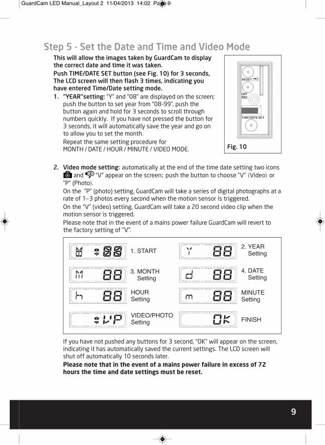
9
2. Video mode setting: automatically at the end of the time date setting two iconsand “V” appear on the screen; push the button to choose ”V” (Video) or
”P” (Photo). On the ”P” (photo) setting, GuardCam will take a series of digital photographs at arate of 1–3 photos every second when the motion sensor is triggered.On the "V" (video) setting, GuardCam will take a 20 second video clip when themotion sensor is triggered. Please note that in the event of a mains power failure GuardCam will revert tothe factory setting of "V".
If you have not pushed any buttons for 3 second, “OK” will appear on the screen,indicating it has automatically saved the current settings. The LCD screen willshut off automatically 10 seconds later.Please note that in the event of a mains power failure in excess of 72hours the time and date settings must be reset.
1. START
3. MONTHSetting
2. YEARSetting
4. DATESetting
MINUTESetting
FINISH
HOURSetting
VIDEO/PHOTOSetting
Step 5 - Set the Date and Time and Video ModeThis will allow the images taken by GuardCam to displaythe correct date and time it was taken. Push TIME/DATE SET button (see Fig. 10) for 3 seconds,The LCD screen will then flash 3 times, indicating youhave entered Time/Date setting mode. 1. “YEAR”setting: ”Y” and “08” are displayed on the screen;
push the button to set year from “08-99”, push thebutton again and hold for 3 seconds to scroll throughnumbers quickly. If you have not pressed the button for3 seconds, it will automatically save the year and go onto allow you to set the month.Repeat the same setting procedure forMONTH / DATE / HOUR / MINUTE / VIDEO MODE. Fig. 10
GuardCam LED Manual_Layout 2 11/04/2013 14:02 Page 9

Step 6 - Viewing VideoViewing image by computer through USB card reader supplied (see Fig. 11) � Open SD card housing with allen key supplied� Press OFF/REC button and remove SD card from the slot.� Put the SD card into the USB card reader supplied, then insert the card reader
into PC via a USB port and open Windows Media Player to view the video.
10
Fig. 11
GuardCam LED Manual_Layout 2 11/04/2013 14:02 Page 10

Technical SpecificationsFeatures and specification:� PIR detection angle 160 Deg and detection range up to 10M� Records 20 seconds image recording for image stream: 10fps at 480*640 Pixels� Built in SD card slot for SD memory card� SD card slot for additional storage, max memory size up to 32GB� SD card spec.: FAT16 (SD) / FAT 32(SDHC� Automatic exposure control, white balance and sharpness � Auto Date & Time stamp� Effective viewing angle: 60 deg� Effective viewing distance: 8M� Image format: JPEG AVI File� Powered by AC 100V to 240V(subject to requirement)� 8pcs 1W Nichia super power white LED� Auto light sensor� Sensitivity control� Floodlight time delay control
11
GuardCam LED Manual_Layout 2 11/04/2013 14:02 Page 11

General Information and SafetySPECIAL CARE INSTRUCTIONS� The GuardCam LED Motion Light with Video Camera is designed to be weather
resistant. Never attempt to immerse the unit in water or any other liquid. This willdamage the unit and void the warranty.
� This product is designed to illuminate, video, and make verbal announcements. It will not prevent the commission of any act, legal or illegal. The manufacturerassumes no liability for any damage to property, injury to person, or death.
� Use a soft lens cloth for cleaning lens. Avoid touching lens with fingers.� Remove dirt or stains with a soft cloth dampened with water or neutral
detergent. Keep the GuardCam LED Motion Light with Video Camera in a dry andcool dust-free environment or container when it is NOT used
� Do not open the GuardCam LED Motion Light with Video Camera for unauthorizedservice. This could cause serious damage to the unit and will void the warranty.
� This GuardCam LED Motion Light with Video Camera is a precision electronicdevice. Do not attempt to service this camera yourself, as opening or removingcovers may expose you to the danger of electric shock or other risks.
� To avoid risk of burns due to high temperature do not touch the floodlight whenit is turned on.
Elite Security ProductsUnit 7, Target Park, Shawbank RdLakeside, Redditch B98 8YN
Telephone: 01527 515150Fax: 01527 515143
email: [email protected]
GuardCam LED Manual_Layout 2 11/04/2013 14:02 Page 12