combined loadings thin-walled pressure vessels cylindrical pressure vesselspherical pressure vessel
Post on 20-Dec-2015
381 views
TRANSCRIPT
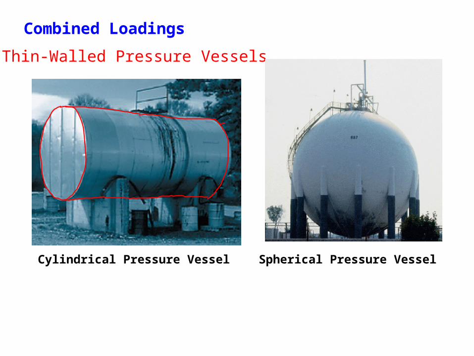
Combined Loadings
Thin-Walled Pressure Vessels
Cylindrical Pressure Vessel Spherical Pressure Vessel

What is Thin?


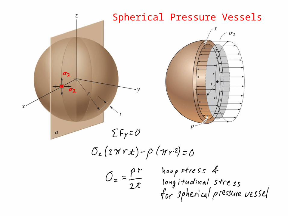
Spherical Pressure Vessels

Guidelines for Determining the Stress State caused by Combined Loadings
Internal Loading
– find internal normal & shear forces and bending and torsional moments – forces act through centroid & moments about centroidal axes
Average Normal Stress
– compute stress associated with each internal load – represent stress acting an element or distribution over cross section
Normal Force
– internal normal force due to uniform stress distribution
Shear Force
– internal shear force in a member subjected to bending is due to a shear-stress distribution determined from the shear formula
Bending Moment
– for straight members, internal bending moment is due to a normal stress distribution determined from the flexure formula

Torsional Moment
– for circular shafts and tubes, the torque is due to a shear stress distribution determined from the torsional formula
Thin-Walled Pressure Vessels
– for cylindrical vessels, the internal pressure causes a biaxial state of stress with hoop and circumferential components
– for spherical vessels, the biaxial state of stress is represented by two equivalent components
Superposition
– use principle of superposition to determine the resultant normal and shear stress components
– show resultants on an element of material located at the point, or show results as a distribution of stress acting over the member’s cross-sectional area
Guidelines for Determining the Stress State caused by Combined Loadings - continued

8-43 Known: The uniform sign is supported by the pipe AB, and is subjected a uniform wind pressure.Find: Determine the state of stress at points C and D. Show the results on a differential volume element located at each of these points.Data: The sign weighs 1500 lb. Pipe AB has an inner radius of 2.75 in. and an outer radius of 3.00 in. The uniform wind pressure p = 150 lb/ft2.Assumptions: Neglect the thickness of the sign, and assume that it is supported along the outside edge of the pipe.
