combined effect of ground presence and heaving motion on a race car wing
DESCRIPTION
MSc Thesis, Matteo de GiovanettiTRANSCRIPT

Combined Effect of Ground
Presence and Heaving Motion on
a Race Car Wing
Matteo de’Giovanetti
Faculty of Engineering and the Environment
University of Southampton
A thesis submitted for the degree of
Master of Science in Race Car Aerodynamics
2013 09

To Time

Abstract
The purpose of this thesis is to investigate, experimentally, the be-
haviour of an inverted wing in ground effect undergoing a sinusoidal
oscillatory motion. In order to do so, a rigid structure has been built
and connected to an existing 80% model of a F1 front wing mainplane.
The experimental procedure has been validated against existing data
and values computed from widely accepted theories.
The tests included the acquisition of time-history of the aerodynamic
loads for three cases: clean wing, wing with a Gurney flap, wing with
a Gurney flap and transition fixed on the suction side. The inde-
pendent variables included Reynolds number, reduced frequency and
ride height. When possible, the results for lift and drag, average and
fluctuation, were compared with computational analyses carried out
on a similar layout, and good agreement was shown. The phase shift
between motion and lift coefficient was studied at different amplitudes
as well. It was possible also to shed light on the effects triggered by
the presence of a Gurney flap on lift and drag, as an increased bene-
ficial effect was observed at very low frequencies, with respect to the
clean wing case.

Non exiguum temporis habemus,
sed multum perdidimus.
Lucio Anneo Seneca, De Brevitate Vitae

vi
Acknowledgements
There is not a single achievement, in the history of mankind, that was reached by a
man on his own. When a theorem, a discovery, a formula is named after someone,
we are forgetting all the people that made it possible. Every time we meet another
element of our species, that individual shapes who we are and what we think, for
the best or the worst, in a sort of large-scale interpretation of quantum mechanics.
It is my intention to mention, in the next paragraphs, all the people that helped
me, in the most diverse manners, throughout this year.
My sincerest gratitude goes to my supervisors, Professor Xin Zhang and Dr. Dave
Marshall, the first for his invaluable insights and life lessons, the second for his
continuous support and feedback on every topic of the project. Similarly, this
thesis as such would not have been possible without the help of Dr. Oksana
Stalnov, Mr. Dave Cardwell, Mr. Mike Thomas.
On a more personal note, the final days of this project have been incredibly
stressful for me. As my laptop and hard drive were stolen from my house, all the
thesis had to be rewritten in the short span of ten days, while re-analysing all
the wind tunnel data. There are not any words in the English dictionary, or any
other dictionary on this planet, that can describe the encouragement, assistance
and backing that I received from my family, and my parents in particular. As it
is my precise purpose of referring to them as a single entity, I have to thank them
for always being a propulsive force behind my actions, a guidance and a model. I
should also be grateful to my sisters, for they to have always been there. As far as
family goes, I also have to thank Mac, for teaching me that there is always time
to play with a ball, and He-Who-Shall-Not-Be-Named, for he knows why.
Many thanks to the few true friends I can count on, and in particular to the one
who bears my same name, and who shared the (few) crests and (many) valleys
of this year, and the greatness of a forgotten Italian painter. I would like also to
thank my coursemates, for they sharing ideas, knowledge and occasionally despair.
Last but not least, it is my firm intention to mention the name that will be echoed
in eternity: BUZZINI!
i

ii

Contents
List of Figures v
1 Introduction 1
1.1 Background and Motivations . . . . . . . . . . . . . . . . . . . . . 2
1.2 Project Objectives . . . . . . . . . . . . . . . . . . . . . . . . . . 3
1.3 Dissertation Layout . . . . . . . . . . . . . . . . . . . . . . . . . . 4
2 Literature Review 7
2.1 Aerodynamics of Racing Cars . . . . . . . . . . . . . . . . . . . . 8
2.2 Inverted Wings in Ground Effect . . . . . . . . . . . . . . . . . . 10
2.3 Unsteady Aerodynamics of Wings . . . . . . . . . . . . . . . . . . 16
2.4 Combined Effect of Oscillations and Ground Presence . . . . . . . 26
3 Research Description 29
3.1 General Approach . . . . . . . . . . . . . . . . . . . . . . . . . . . 29
3.2 Test Programme . . . . . . . . . . . . . . . . . . . . . . . . . . . 30
3.3 Assumptions . . . . . . . . . . . . . . . . . . . . . . . . . . . . . . 32
3.4 Experimental Setup . . . . . . . . . . . . . . . . . . . . . . . . . . 34
4 Results and Discussion 43
4.1 Preliminary Study . . . . . . . . . . . . . . . . . . . . . . . . . . 43
4.2 Clean Wing . . . . . . . . . . . . . . . . . . . . . . . . . . . . . . 47
4.3 Gurney Flap . . . . . . . . . . . . . . . . . . . . . . . . . . . . . . 56
5 Conclusions and Further Work 61
iii

CONTENTS
References 65
iv

List of Figures
2.1 Chaparral 2C . . . . . . . . . . . . . . . . . . . . . . . . . . . . . 10
2.2 Modified pressure distribution for double-element wing in ground
effect . . . . . . . . . . . . . . . . . . . . . . . . . . . . . . . . . . 11
2.3 Spanwise velocity vectors for wing in ground effect . . . . . . . . . 12
2.4 Time-averaged momentum in the wake of a plunging aerofoil in
freestream . . . . . . . . . . . . . . . . . . . . . . . . . . . . . . . 16
2.5 Dynamic stall mechanism for pitching aerofoil . . . . . . . . . . . 20
2.6 Phase shift as a function of reduced frequencies at different ride
heights . . . . . . . . . . . . . . . . . . . . . . . . . . . . . . . . . 28
3.1 CAD rendering of entire wing assembly . . . . . . . . . . . . . . . 35
3.2 Wing in the wind tunnel . . . . . . . . . . . . . . . . . . . . . . . 36
3.3 Example of task decomposition . . . . . . . . . . . . . . . . . . . 38
3.4 Block diagram for Labview software . . . . . . . . . . . . . . . . . 41
4.1 FFT of vertical-force signal . . . . . . . . . . . . . . . . . . . . . 44
4.2 Lift signal . . . . . . . . . . . . . . . . . . . . . . . . . . . . . . . 45
4.3 Example of lift signal post-processing . . . . . . . . . . . . . . . . 46
4.4 CD and CL vs. wind speed, freestream . . . . . . . . . . . . . . . 47
4.5 Phase shift between lift and motion, comparison between experi-
mental and computed values . . . . . . . . . . . . . . . . . . . . . 48
4.6 Lift coefficient, comparison between experimental and computed
values . . . . . . . . . . . . . . . . . . . . . . . . . . . . . . . . . 48
4.7 Lift and drag coefficients vs. ground clearance . . . . . . . . . . . 49
4.8 Efficiency vs. ground clearance . . . . . . . . . . . . . . . . . . . 50
v

LIST OF FIGURES
4.9 Average lift coefficient vs. frequency and Reynolds number . . . . 51
4.10 Average drag coefficient vs. frequency and Reynolds number . . . 53
4.11 Average lift coefficient vs. reduced frequency and ride height . . . 54
4.12 Phase shift vs. reduced frequency . . . . . . . . . . . . . . . . . . 55
4.13 Phase shift vs. motion amplitude . . . . . . . . . . . . . . . . . . 56
4.14 Lift and drag coefficients vs. wind speed, GF and TFX . . . . . . 57
4.15 Non-dimensional oscillation factor, lift and drag, GF and TFX . . 58
4.16 Non-dimensional lift and drag vs. reduced frequency, GF and TFX 59
4.17 Phase shift vs. reduced frequency for different cases . . . . . . . . 60
vi

Glossary
CAD Computer Aided Design
CFD Computational Fluid Dynamics
GF Gurney Flap
F1 Formula 1
FFT Fast Fourier Transform
FW Front Wing
KVS Karman Vortex Street
LDA Laser Doppler Anemometry
LE Leading Edge
MAV Micro Aerial Vehicle
PIV Particle Image Velocimetry
RVKS Reverse Karman Vortex Street
TE Trailing Edge
TFX Transition fixed
UAV Unmanned Aerial Vehicle

LIST OF FIGURES
Nomenclature
α0 Geometric angle of attack ◦
αeff Effective angle of attack ◦
a Motion amplitude mm
C(k) Theodorsen function
CDD
1/2ρSU∞Drag coefficient
CLL
1/2ρSU∞Lift coefficient
c Wing chord mm
D Drag N
E Young’s modulus Mpa
E Average increase in energy per unit time W
f Motion frequency Hz
k πfcU∞
Reduced frequency
h/c Non-dimensional ground clearance
h Wing position
h −cos(φ) Non-dimensional phase shift
h ac
Non-dimensional motion amplitude
L Lift N
q Freestream dynamic pressure Pa
M U∞c
Mach number
Px Propulsive power W
viii

LIST OF FIGURES
φ Phase shift ◦
Re ρU∞xν
Reynolds Number
ρ Flow density
S Planform area m2
σ Standard deviation
t Time s
Tu√u′2
U∞Turbulence intensity
U∞ρU∞xν
Freestream velocity m/s
u′ Velocity fluctuation m/s
W Weight kg
W Average power W
y Half length of the strut mm
ix

LIST OF FIGURES
x

1
Introduction
Without any doubt, the best researcher in the world is Nature itself. There is
not a more decisive incentive for improvement and advancement than the quest
for survival, which requires animals, and most of the living creatures, to be-
come faster, stronger, tougher as time goes by, and while Nature itself, with
the evolutionary process, provides their predators with increasingly powerful and
dangerous weapons to ultimately kill them. This mechanism is not unlike any
sport, where the smallest detail can make the difference between winning and
losing, rather than living or dying.
It is therefore sensible to look with curious and inquisitive eye at what Nature
shows us, and try to extract all the lessons we can. In science and engineering
especially, Nature can represent an incredible and invaluable source of inspiration
and provide the basis for technological breakthroughs. Fluid mechanics makes no
exception, as the first to gain an insight from biological creatures was arguably
Leonardo da Vinci himself, who tried, somehow successfully, to reproduce the
wing of a bird and to understand the mechanisms that allow such beautiful crea-
tures to fly and glide. Nowadays, many features of living creatures are being
studied in an attempt to improve both our knowledge and our resource man-
agement; for what concerns fluids, it is valuable to mention the studies on the
compliant surfaces of dolphins (1) (2) (3), rough surfaces (riblets) on sharks (4)
(5) (6), wavy leading edges on whales (7) (8) (9) (10), and the overall dynamics
of flight, from the sheer speed of the peregrine falcon to the gracious nimbleness
of the swallow.
1
1. INTRODUCTION
Regarding biological flight, many attempts have been made to comprehend and
reproduce it in laboratory, both from a dynamical and structural point of view.
For the former, it is possible to state that the wing motion for a bird is a combi-
nation of heaving, pitching and fore-aft motion, commonly referred as flapping.
Applications of these findings range from nano-UAVs (Unmanned Aerial Vehi-
cles), to small MAVs (Micro Aerial Vehicles) and larger-sized UAVs; recently, the
influence of these types of motion has been studied in relation with even larger
structures, including racing cars, with the final aim of improving efficiency and
performance.
1.1 Background and Motivations
The influence of aerodynamics in the design of racing cars has steadily increased
in the last decades, and, nowadays, is doubtlessly the most influential factor for
performance. The front wing is one of the most important devices on the entire
car, and is responsible for the production of downforce, as well as being the only
element to encounter freestream conditions. The wing is generally static, and
is rigidly connected to the rest of the car through two pillars mounted at the
centre of the wing. Apparently, the safety factors employed in the dimensioning
of these pillars are not high, as it has been proven by a number of failures in
these components (see for example Alonso at Sepang 2013). As a matter of
fact, the high levels of downforce produced by the wing, as well as the internal
compliance of carbon fibre, induce modifications in the shape at high speeds:
the wing endplates tend to get closer to the ground, introducing a curvature in
the wing. Another effect that can be triggered is the vibration of the wing, as a
further consequence of the flow-structure interaction coupled with the anisotropic
stiffness of carbon fibre. It is therefore interesting to investigate the influence
that these vibrations-oscillations can induce, from two standpoints mainly: one
is the gain in pure performance, the other is on the maximum forces that can be
generated, in order to prevent dramatic failures.
The topic of heaving and pitching wings has been widely investigated from the
point of view of applicability to Micro Aerial Vehicles (MAVs), small and light
devices that operate in Reynolds numbers in the order of magnitude of 102−103:
2
1.2 Project Objectives
unsteady effects are exploited to produce thrust, without any other streamwise-
aligned power device to generate motion. The related increase in lift, with respect
to static conditions, is also a research subject. Many of the inspirations for the
design of these small devices come from biological flyers, such as dragonflies,
similar insects and small birds.
Very few studies have been realised merging these two topics, or with particular
focus on motorsport applications; moreover, CFD has always been the preferred
method to carry out these investigations. The combined influence of unsteady
aerodynamics and ground effect on a generic race car front wing has not been
widely explored yet from an experimental point of view, especially in the range of
Reynolds number of 105. This deficiency has been the main driving force behind
the project.
1.2 Project Objectives
The principal target of this project is to improve the existing knowledge on the
behaviour of an inverted wing in close proximity to the ground while undergo-
ing oscillatory motion, with the employment of wind tunnel testing. The results
are to be referred to F1 cars and, more broadly, to motorsport applications.
This requires a careful assessment of the suitability and feasibility of wind tunnel
testing for such a case, with specific reference to Reynolds number and motion
frequency, and the technological bounds that are posed by state-of-the-art facil-
ities. The main goals can only be achieved if some intermediate objectives are
met, as listed below:
1. As the nature of this project is completely experimental, the required layout
has to be specified and, if necessary, designed and built. Since the wind
tunnel to be used was known from the start, the first goal was to prepare an
experimental setup capable of providing the required data: this involves all
the aspects connected with experimental testing, such as physical models,
control software and data acquisition.
2. The second objective is strictly connected with the first and indeed intrinsic
to the primary intent as well: understanding the current state of knowledge
3

1. INTRODUCTION
in the field of unsteady aerodynamics, in particular for the cases of ground
effect and heaving motion. This entails the careful review of existing liter-
ature of the subject, in order to correctly steer the ensuing research.
3. Once the first two objectives are completed, the actual testing can begin.
The acquisition of a coherent, consistent and accurate set of data is con-
sidered as an inevitable step and objective, and one not to be overlooked.
It is to be noted how an initial appraisal of wind tunnel capabilities is
of the foremost importance. This will entail the comparison of a simple
case to existing theories, to the positive outcome of which all the following
investigation is subordinated.
4. All the data acquired need to be analysed, taking into account what was
defined in the second step as of primary importance. Again, only a well-
documented and precise data processing can lead to meaningful results. The
objective here is therefore to prepare a programme capable of handling all
the data in a consistent and unique way, and to return significant quantities
and results, as required by the specific objectives outlined in the previous
steps.
5. The final and foremost objective is to draw conclusions based on the infor-
mations from the previous step, compare them with what was extracted in
step two and provide the reader with brief conclusions and suggestions to
steer further work.
1.3 Dissertation Layout
Where possible, this dissertation tries to follow a logical order in the first place,
and a chronological one where not possible, in order to make it as understandable
as possible. This document is consequently structured as follows:
• The second chapter is a survey of the relevant literature. A quick overview
of the influence of aerodynamics on racing cars serves as the introduction to
the two main features that pertain to this study: inverted wings in ground
effect and wings undergoing one or two-degree-of freedom motion, mainly
4

1.3 Dissertation Layout
heaving. A review of the few articles dealing with these two configurations
in conjunction follows.
• The third chapter involves an explanation of all the main facilities, models
and data processing techniques employed during the entire course of the
project. Relevant assumptions for the validity of the study and the testing
programme respectively open and close the chapter.
• The fourth chapter is a comprehensive account of all the results obtained,
both for the preliminary investigation and the main one, including addi-
tional testing.
• The fifth chapter winds up the dissertation by presenting the conclusions
and suggestions for further work. It can be observed how the objectives
described in the previous section and the chapters contents are very similar,
which allows every part to be logically meaningful as a stand-alone section.
5

1. INTRODUCTION
6

2
Literature Review
This chapter presents an overview of the available literature that can be helpful
in building the fundamentals of the project. Given the inclination of this study
towards motorsport applications, a brief overview of the history and current role
of aerodynamics in racing cars is offered. The remainder of the chapter is more
pertinent to the actual physics of this study, and is divided into three sections:
the first presents an introduction to the ground effect for inverted wings, and
effort was made in order to cover every and each of the significant points of this
topic. The second section is an account of the recent progress made in the field
of unsteady aerodynamics, when plunging and pitching wings are considered. In
contrast with the previous part, it was deemed as unreasonably time-consuming
and verbose to display all the research carried out with regards to the aforemen-
tioned problems, as a comprehensive review would encompass the entire field of
unsteady aerodynamics. In attempt to be both exhaustive and concise, the fun-
damentals of the discipline are presented, which date back to the 1920s and 1930s.
Afterwards, the main research of the last 15-20 years is put forward, in order to
illustrate the most recent findings; obviously this means that, time-wise, a gap is
present, but care was made to bridge it with small introductory paragraphs. The
third and final section details the little existing research already carried out on
the combination of these two broader topics.
7

2. LITERATURE REVIEW
2.1 Aerodynamics of Racing Cars
The field of aerodynamics can be considered relatively young, especially when
compared to the subjects of solid and fluid mechanics in general. Aerodynamics
as a separate subject became relevant as aircraft technology advanced, and the
main findings have been successfully applied to race cars in the last 50 years.
More recently, the particular conditions in which a race car finds itself, i.e. being
in contact with a surface that constrains the flow under the car, has justified
the existence of research specifically focused on this topic. It is worth mention-
ing that, as a consequence of the increased attention and awareness towards the
environment, in the last years a number of studies have been carried out on pas-
senger cars as well, mainly aimed at reducing the drag at moderate speed, to cut
large-scale fuel consumption.
Taking a step back in time, at the very beginning of automotive history, aero-
dynamic effects were not considered to be an issue of any sort for cars, given,
basically, the very low speeds that were involved. As technology progressed, these
vehicles were able to attain higher speeds, with the first car to actually break the
100 km/h barrier being the Jamais Contente, driven by Camille Jenatzy (11). In
these early days, the only aerodynamic-driven focus was to reduce the drag as
much as possible, which meant that cars were shaped as bullets or even styled as
raindrops, an example of this being the well-known A.L.F.A. 40-60 HP Castagna
Siluro Aerodinamica commissioned by Count Ricotti in 1914 (12). Perhaps the
first man to understand the potential of aerodynamic loads perpendicular to the
ground produced by a car, Ettore Bugatti designed the 1923 Type 32 Tank de
Tours to be fitted with an aerofoil-shaped bodywork, which produced lift. The
intuition was bright, the application was not. Many incidents, and even notable
fatalities, were triggered by aerodynamic effects, in particular when land speed
record were attempted and the speeds quickly rose up to 400 km/h and beyond,
the most famous case being the death of Auto Union driver Bernd Rosemeyer.
The main instance continued to be drag reduction, and even the studies by two
pioneers of automotive aerodynamics, Dr. Wunibald Kamm and Baron Reinhard
von Koenig-Fachsenfeld (13), were focused on this matter exclusively.
Despite an early, soon-to-be-forgotten attempt made by Opel, it was not until
8

2.1 Aerodynamics of Racing Cars
the 1960s that effective aerodynamic device were fitted to a racing car, the first
example being the number of features that appeared in a short time on the Cha-
parral 2 (14). Specifically, the 2C is more often than not believed to have started
the legacy that still endures today, with the introduction of air dams at the front
and an adjustable, inverted wing at the rear end. This car, and its successors,
enjoyed such a number of victories that the idea of inverted wings was picked up
by Formula 1 teams in 1968, and by the end of this year all the cars on the grid
were equipped with these devices. In order to improve balance, a further wing
was added to the front end, close to the ground (15). The first wings were im-
ported directly from aeronautical industry: this procedure proved to be initially
effective, but engineers soon realised that working condition on aeroplanes and
racing cars were very much diverse (16).
The second big aerodynamic revolution in F1 was represented by the increasing
comprehension of ground effect, with the first car designed around this concept
being the Lotus 78, which was then perfected and raced as the iconic Lotus 79.
The introduction of skirts, that sealed the underbody creating perfect channels
under the car, made possible to reach massive amount of downforce and conse-
quently cornering speeds (17).
The influence of aerodynamic devices on modern F1 cars performance is higher
than any other component, be it the engine, suspensions or electronics. The
downforce generated in high-speed bends can reach up to 3 or 4 times the weight
of the car, and the aerodynamic efficiency is well above three, depending on track
characteristics; wings and diffuser play a major role in the downforce genera-
tion process. It is interesting to point out that also the location of the centre of
pressure can highly affect the performance of the car, making the aerodynamic
balance another significant parameter to monitor during the design process (18).
A number of researches have been carried out on particular components of racing
cars, in an attempt to utilise an academic approach to an industrial problem,
consequently focusing not only on the pure performance, but also on the funda-
mental physics and features governing the flow: besides several articles published
on front wings, studies have been published on diffusers (19) (20) (21) (22) and
on wheels (23) (24), also with reference to their influence on the front wing (25)
9

2. LITERATURE REVIEW
(26). It is anyway clear how the research into new concepts, and the continu-
ous, systematic betterment of the known ones, is pushed to the limit, and even
infinitesimal improvements can make the difference on track. It is consequently
clear how this dissertation places itself into this continuous strive for advance.
Figure 2.1: Chaparral 2C
2.2 Inverted Wings in Ground Effect
The purposes of a front wing are mainly three: increase the total downforce of
the car, bring the centre of pressure forward, and shape the flow in a beneficial
way for the downstream components, such as diffusers, sidepods and rear wing.
The front wing of a racing car produces a considerable portion of the total down-
force generated by the car, and in general can be assumed to be around 30% and
40% of this value (27) (28). The wing is placed very close to the ground, with
distances that are normally lower than 100 mm (29), and therefore smaller than
the chord of the wing itself. This means that the effect of the ground cannot
be neglected, and that the influence of this wall on wing performance is of the
highest importance.
First mention of the modified pressure distribution of an inverted wing in prox-
imity of a wall is to be found in Zahm and Bear (30), who noticed how both lift
and drag substantially increased with respect to free-stream conditions. It was
not until the 1980s that systematic investigations of inverted wings in ground
effect began. A quantitative description of the modified pressure field for a wing
10

2.2 Inverted Wings in Ground Effect
Figure 2.2: Modified pressure distribution for double-element wing in ground ef-
fect, from (18)
and flap configuration can be found in Dominy (31), who also stresses the impor-
tance of tip effects and consequently the necessity of endplates. The influence of
the aspect ratio of the wing has been studied by Katz (32) (33), who showed a
remarkable influence of finite-span effects, while the effects of wing geometrical
parameters, such as thickness and camber, has been explored by Coulliete and
Plotkin (34).
The first comprehensive set of tests on a wing in ground effect was carried out
by Ranzenbach and Barlow: a number of experimental and computational simu-
lations was carried out, both on single-element wings (35) (36) (37) and double-
element wings (38). The influence of ride height on wing performance was ex-
plored, at a constant angle of attack. The point of maximum downforce was
found to be at a non-dimensional ride height of 0.08, for a single element. The
reason for the subsequent downforce reduction was believed to be the merging
of aerofoil and ground boundary layers. It is to be noted how the wind tunnel
used in these tests employed a fixed ground, meaning a thicker boundary layer is
formed. This could have affected the transferability of results to race conditions.
The first introduction of a moving ground is linked to Knowles et al. (39), but the
results obtained are of little interest for real-case scenarios, as three-dimensional
effects are not discussed. It is worth mentioning that the incompressibility limit
11

2. LITERATURE REVIEW
Figure 2.3: Spanwise velocity vectors for wing in ground effect, from (41)
for ground effect is M = 0.15, as detailed by Doig et al. (40); shockwaves appear
from M = 0.4 onwards. These former results on the effect of compressibility
can help to explain the discrepancies that sometimes are observed between ex-
perimental and computational studies: at very low ground heights and Mach
numbers in the order of 0.1, an underprediction of force coefficients is a char-
acteristics of incompressible solvers, that are often used in order to make the
computational cases quicker to solve. The most complete set of studies in this
field was published as a result of the research completed by Zhang and Zerihan.
This study included a single-element wing (41) (42) and a double-element wing
(43) and (44). Subsequent overviews of the characteristics of the wake for these
two cases were performed by Mahon and Zhang (45) (46). The influence of inflow
conditions was investigated by Soso and Wilson (47) (48). Remarkable results
were obtained; only the ones regarding the particular geometry used in this study
will be reported.
For a single element wing, three clear regions, depending on ground clearance,
were pointed out: force enhancement, enhancement slowdown, force reduction
(41). The first is related to the downforce growth experienced by the wing when
moving closer to the ground; at a certain distance, depending on other parame-
ters such as angle of attack and Reynolds number, the rate of downforce increase
is reduced. The enhancement slowdown region ranges from 0.15c to 0.3c, with
the latter value valid for a near-stall angle of attack. The maximum downforce
is obtained at ride heights between 0.1 and 0.15, with the gains in downforce
being more relevant at lower angles of attack. After this peak, the values for
downforce drop systematically: the reason for this is postulated to be the in-
12

2.2 Inverted Wings in Ground Effect
creasingly large adverse pressure gradient encountered by the flow on the suction
side, with regions of separated flow appearing at the trailing edge. Drag is found
to grow continuously when reducing ride height, and the rate of increase is ac-
tually larger in the force reduction region: it is therefore clear that this region
should be avoided, as the wing performance drops dramatically. From the point
of view of flow features and aerodynamic coefficient, the presence of the ground
can be modelled to work analogously to an increased angle of attack for a wing
in freestream (49).
Two main features are believed to affect the force generation process: the Venturi-
like channel formed between the suction side and the ground, and the edge vortex
that is being formed beneath the two spanwise extremities of the wing. The first
is responsible for the further acceleration experienced by the fluid shortly down-
stream of the leading edge, as the region between the lowest point of the wing and
the trailing edge effectively forms a diffuser, thus increasing the suction peak by
means of pressure pumping. Another significant feature is represented, as said,
by the lower edge vortices, which effectiveness can be enhanced by the presence
of endplates. As a matter of fact, the pressure differential across the two sides of
the endplate attracts fluid from the external side, fluid that rolls up and forms a
vortex beneath the wing itself, further reducing the pressure. The separation on
the suction surface is also delayed as a consequence of the increased mixing gener-
ated by this vortex. Induced drag is also raised by this flow feature. Overall, this
type of flowfield is remarkably different from the almost two-dimensional one that
can be observed at centre span. As the ground height is further reduced, the vor-
tex moves inboard and grows in size (42). Vortex meandering is observed in the
enhancement slowdown region, and the vortex ultimately breaks down right after
the maximum downforce peak, triggering instantaneous and large-scale separa-
tion. The interaction existing between the lower and upper edge vortices created
by the endplate has been studied by Galoul and Barber (50): they showed how
the lower vortex has a strength remarkably higher than the upper one, which is
in turn bent downwards. At a certain point the two vortices merge.
Reynolds number effect on lift and drag was investigated by Jasinski and Selig
(51), who performed a comprehensive analysis including various type of wings
from Champ cars and F1 cars. They showed how an increase in this parameter
13

2. LITERATURE REVIEW
corresponds to a slight reduction in drag and a marginal increase in lift. De-
spite mentioning that, at low angles, the net positive changes in induced drag
are actually lower than the reductions in profile drag, they also proceed to state
that, when a flap is installed, front wing drag generation is dominated by in-
duced effects; no definitive conclusion seems to be reached. A reduction in peak
downforce has been found as the Reynolds number decreases (41), as well as an
increase in drag at all ride heights.
A further analysis on the Tyrrell 026 wing in ground effect was put forward by
Vogt and Barber (52), in particular on the pressure distribution on the wing: the
stagnation point was measured to move towards the ground as the wing is low-
ered. Consistently with previous research, an increase in suction on the pressure
side was shown; the pressure on the upper side is almost unchanged as the wing
approaches the ground, especially with respect to the suction side.
2.2.1 Gurney Flap
The Gurney flap is a small device generally fitted to the trailing edge of the last
element of a wing, in order to increase maximum lift. It consist of a strip that is
mounted perpendicular to pressure side, with a size between 1% and 5% of the
wing chord. Documents showing a device of this type appeared across the 30s
and 40s (53) (54). It was Dan Gurney, an American driver, who first introduced
this strip on racing cars in the 1960s, and it was then widely adopted by teams all
over the world, taking the name of the inventor. Despite its broad employment,
the reasons for improved performance are not yet a clear phenomenon.
One of the very first investigations on the Gurney flap was carried out by Liebeck
(55), who performed wind tunnel testing, observed a decrease in drag and, at the
same time, an increase in lift. Reversed flow was also detected over the back sur-
face of the Gurney flap, as well as behind it. Two little counter-rotating vortices
are supposed to be the source of this latter flow reversal. The actual improve-
ments in performance are indicated to be a function of aerofoil thickness and
trailing edge shape, as already suggested by Duddy (54). Further research (56)
(57) showed that the Gurney flap has the same effect as increasing the camber of
the aerofoil, changing the angle of attack of zero lift, but not modifying the slope
14

2.2 Inverted Wings in Ground Effect
of the lift curve. Furthermore, the Kutta condition is not valid when the flap
is fitted (58); its effectiveness is higher when its height is equal to the boundary
layer thickness at the trailing edge, on the pressure surface (59). The increase
in lift has been explained with the fact that the wake is turned downwards by
the presence of the flap. Additionally, a decrease in pressure on the suction side,
coupled with an increase on the pressure side, was detected.
A more recent research showed that the drag is slightly increased by the presence
of the Gurney flap, associated with a growth in maximum lift coefficient. An
investigation into three-dimensional wings showed that an inboard placement is
more effective that an outboard one.
The first study to include a time-history visualization of the flow structures of
a Gurney flap was carried out by Jeffrey et al. (60), opposed to the previous
ones, that focused solely on time-averaged data. Vortex shedding is observed to
take place, as a consequence of the interaction between the free-shear layers; the
separation point on the pressure side is fixed, whereas it moves upstream on the
suction side as the angle of attack increases: this is believed to affect the size and
motion of the shed vortices, but indeed not their presence in the wake. More-
over, the finite distance existing between the two surfaces at the trailing edge is
designated as the cause for the increase in circulation, and ensuing increase in
lift. The increase in lift is also believed to be a direct consequence of the vortex
shedding, which enhance the suction peak on the lower surface. The maximum
improvement in lift coefficient was measured to be +90% at null angle of attack,
and around +30% at stall angle, for a 4% Gurney flap. Drag increased as well,
but did not overshadow the gain obtained in lift, meaning that increased effi-
ciency was measured. These improvements are not directly proportional to the
height of the Gurney flap, as a 0.5% GF shows already remarkable enhancement
with respect to the baseline; the rate of increase of lift reduces as the height is
raised. It is postulated that beyond a height of 0.05 times the chord, the benefits
of further increasing Gurney flap dimensions would be negligible. The beneficial
effect measured on single-element wings is generally replicated by double-element
wings (61), even thus the maximum increase in downforce is somewhat lower in
this latter case.
An examination on the effects of the aerofoil on the effectiveness of Gurney flaps
15

2. LITERATURE REVIEW
Figure 2.4: Time-averaged momentum in the wake of a plunging aerofoil in
freestream, from (63)
has been carried out by Cole et al. (62): profiles that feature a very early sepa-
ration on the suction surface show a lower rate of lift growth, or even a reduction
in lift coefficient. This is in accordance to what observed before on the effect of
vortex shedding on the suction peak of the wing.
2.3 Unsteady Aerodynamics of Wings
The literature on heaving-pitching wings is vast and spans within a disparate
range of Reynolds numbers, shapes, applications and so on. Where possible, only
16

2.3 Unsteady Aerodynamics of Wings
the aspects relevant to this study have been investigated. Analytical expressions
for potential flow involving heaving and pitching motion for an aerofoil have been
developed by Theodorsen (64) and Garrick (65) respectively, and constitute the
basis for all subsequent studies.
The first aspect related to a moving wing is the reduction in drag that can ul-
timately result in drag reversal and thrust production, a phenomenon that was
first observed by Knoller (66) and Betz (67) independently. Karman and Burgess
(68) proceeded to postulate the dependence of this force on the the structure of
the wake, and in particular on the presence of alternate vortices behind the wing.
The existence of a vortex sheet downstream of a heaving wing has been therefore
studied and then decisively proven in a number of articles (69) (70) (71). The
presence of vortices in the wake is not only related to heaving motion but can
take place also for a stationary aerofoil because of a number of causes, all leading
to shear instabilities at the trailing edge (72). In the case of a Karman Vortex
Street (KVS), vortices that are shed in the wake are aligned in such a away to pro-
duce a momentum deficit, thus generating drag. Heaving and pitching motions
have the potential to modify the relative distribution of these vortices, leading to
different wake structures. This changes can lead to a RKVS (Reverse Karman
Vortex Street), where the time-averaged momentum shows a jet-like momentum
gain, which defines thrust production. In particular, the vortex with positive
circulation is moved to the upper part of the wake, and the one with negative
circulation is moved to the lower part (73). Young and Lai (74) also noticed how
the VKS can actually be substituted by a wake containing multiple vortices per
cycle, thus denying the fact that the non-dimensional amplitude kh can be used
as the only parametre to assess the type of wake structure.
The dependence of the wake structure on the Strouhal number St was proposed
by Lai and Platzer (75); experimental tests performed using this similarity pa-
rameter for comparison yielded good accordance to the computational efforts of
Triantafyllou and Grosenbaugh (76). Both computational and experimental ap-
proaches have been tried to understand the complicate process of drag reversal.
It is to be noted how the VKS is an intrinsically unsteady process, with all the
vorticity concentrated in different points in the wake, thus making modelling a
very complicated matter (77).
17

2. LITERATURE REVIEW
Interestingly, the range of St capable of producing constant and well-behaved
thrust is exactly the one in which fish and biological flyers operate, as detailed
by Drucker (78) and Wolgang et al.(79).
The actual parameters governing the drag-thrust transition have been widely
discussed, and still represent a partially open question. Godoy-Diana et al. (80)
studied the wake of a flapping aerofoil by means of PIV, at Re in the order of 103.
It was found that the type of the wake closely depends on two parameters, these
being the Strouhal number St and the amplitude AD of the motion itself. For
neutral and reverse wake to take place both the values should be above a certain
threshold, measured to be 0.1 for StA and 0.5 for AD. The regions containing
the same wake are delimited by curves similar to parabolae. This result justifies
the introduction of a new parameter, the amplitude-based Strouhal number StA,
capable of containing both informations at the same time: the sole value of StA
is enough to mark the lower boundary for thrust production. Another feature
indicated by PIV is the deflection of the wake as the frequency and amplitude of
motion are further increased. The existence of a neutral type of wake, with per-
fectly aligned vortices and negligible drag has been confirmed by He et al. (81).
The deflection of the wake at St > 0.5 has been observed by von Ellenrieder et al.
(63), who postulated that the onset of asymmetric wake depends on both reduced
frequency and non-dimensional heave velocity. Results were in accordance with
what already proposed by Lewin and Haj-Hariri (82). Wake deflection seems to
dependent on the initial motion (whether upwards or downwards) and influenced
by the flow features in the very first moments of the heaving motion. They also
confirmed the results obtained previously by Liang et al. (83), who discovered a
positive correlation between deflection angle and Re at fixed St.
It is worthwhile to mention that the vast majority of these studies is computa-
tional, and has been carried out on two-dimensional models. Three dimensional
effects include the suppression of vortex shedding for very low aspect ratio wings.
Another effect triggered by a vertical motion of a wing is the dynamic stall,
which includes the dramatic increase in post-stall lift as the wing pitches and
plunges. This effected is believed to be triggered by the existence of a Leading
Edge Vortex (LEV), consisting of a small spanwise vortex close to leading edge
18
2.3 Unsteady Aerodynamics of Wings
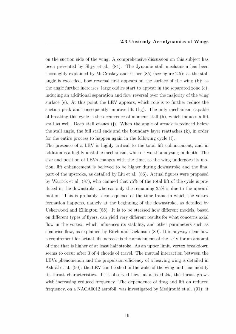
on the suction side of the wing. A comprehensive discussion on this subject has
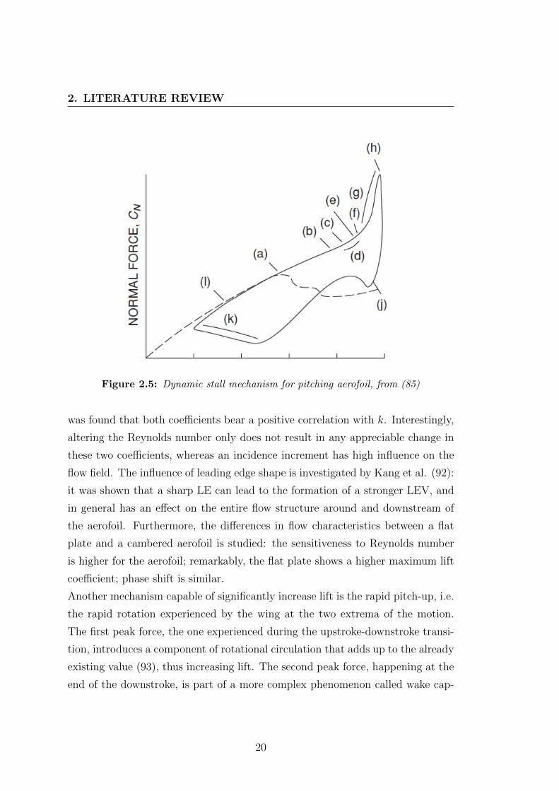
been presented by Shyy et al. (84). The dynamic stall mechanism has been
thoroughly explained by McCroskey and Fisher (85) (see figure 2.5): as the stall
angle is exceeded, flow reversal first appears on the surface of the wing (b); as
the angle further increases, large eddies start to appear in the separated zone (c),
inducing an additional separation and flow reversal over the majority of the wing
surface (e). At this point the LEV appears, which role is to further reduce the
suction peak and consequently improve lift (f-g). The only mechanism capable
of breaking this cycle is the occurrence of moment stall (h), which induces a lift
stall as well. Deep stall ensues (j). When the angle of attack is reduced below
the stall angle, the full stall ends and the boundary layer reattaches (k), in order
for the entire process to happen again in the following cycle (l).
The presence of a LEV is highly critical to the total lift enhancement, and in
addition is a highly unstable mechanism, which is worth analysing in depth. The
size and position of LEVs changes with the time, as the wing undergoes its mo-
tion; lift enhancement is believed to be higher during downstroke and the final
part of the upstroke, as detailed by Liu et al. (86). Actual figures were proposed
by Warrick et al. (87), who claimed that 75% of the total lift of the cycle is pro-
duced in the downstroke, whereas only the remaining 25% is due to the upward
motion. This is probably a consequence of the time frame in which the vortex
formation happens, namely at the beginning of the downstroke, as detailed by
Usherwood and Ellington (88). It is to be stressed how different models, based
on different types of flyers, can yield very different results for what concerns axial
flow in the vortex, which influences its stability, and other parameters such as
spanwise flow, as explained by Birch and Dickinson (89). It is anyway clear how
a requirement for actual lift increase is the attachment of the LEV for an amount
of time that is higher of at least half stroke. As an upper limit, vortex breakdown
seems to occur after 3 of 4 chords of travel. The mutual interaction between the
LEVs phenomenon and the propulsion efficiency of a heaving wing is detailed in
Ashraf et al. (90): the LEV can be shed in the wake of the wing and thus modify
its thrust characteristics. It is observed how, at a fixed kh, the thrust grows
with increasing reduced frequency. The dependence of drag and lift on reduced
frequency, on a NACA0012 aerofoil, was investigated by Medjroubi et al. (91): it
19
2. LITERATURE REVIEW
Figure 2.5: Dynamic stall mechanism for pitching aerofoil, from (85)
was found that both coefficients bear a positive correlation with k. Interestingly,
altering the Reynolds number only does not result in any appreciable change in
these two coefficients, whereas an incidence increment has high influence on the
flow field. The influence of leading edge shape is investigated by Kang et al. (92):
it was shown that a sharp LE can lead to the formation of a stronger LEV, and
in general has an effect on the entire flow structure around and downstream of
the aerofoil. Furthermore, the differences in flow characteristics between a flat
plate and a cambered aerofoil is studied: the sensitiveness to Reynolds number
is higher for the aerofoil; remarkably, the flat plate shows a higher maximum lift
coefficient; phase shift is similar.
Another mechanism capable of significantly increase lift is the rapid pitch-up, i.e.
the rapid rotation experienced by the wing at the two extrema of the motion.
The first peak force, the one experienced during the upstroke-downstroke transi-
tion, introduces a component of rotational circulation that adds up to the already
existing value (93), thus increasing lift. The second peak force, happening at the
end of the downstroke, is part of a more complex phenomenon called wake cap-
20

2.3 Unsteady Aerodynamics of Wings
ture. All the effects due to the interaction between the wing and the wake fall
under the wake capture nomenclature: in particular, the features that influence
flow characteristics on the suction surface are hereby discussed. The increase
in lift during this inversion is considered to be a consequence of the increased
velocity on the suction side (94); some doubts still exist on the real nature of
this force peak, as detailed in Sunada and Ellington (95), who postulate that this
improvement is only a consequence of the added mass effect.
The relative magnitude and influence of various flow phenomena, at different St,
has been studied by Andro et Jacquin (96): when the Strouhal number is lower
than 0.1, the only significant lift enhancement mechanism is represented by the
presence of the leading edge vortex, which accounts for a quasi steady circulatory
force. As St in increased, both added mass and wake capture start to play a
relevant role too. As St is beyond 0.5, the acceleration grows accordingly, thus
increasing the importance of the added mass effect, which becomes the only sig-
nificant source of lift enhancement. Moreover, the wake capture seems to work
best at St = 0.4, and as this value is surpassed, the vortices being shed decrease
in size, thus reducing the mean lift.
Another important factor in the process of leading edge vortices shedding is the
thickness of the wing, which strongly affects both the formation and the shedding
timing. As explained by Yu et al. (97), aerofoil below a certain thickness do not
shed the LEV in the wake; instead, the LEVs remain close to the leading edge
for the entire cycle. This introduces an aperiodic component in the aerodynamic
loads, and in particular in the thrust production.
2.3.1 Theodorsen’s Theory
In 1935, Theodore Theodorsen performed a comprehensive theoretical analysis
of the unsteady aerodynamics of an aerofoil and aerofoil-aileron (sic), using non-
stationary potential flow theory and applying the Kutta condition at the trailing
edge. A theory based on infinitely small oscillations was developed, which should
not be affected by the aerofoil characteristics such as thickness and camber. Three
forces were considered, as explained by Theodorsen himself: the inertia forces,
the restraining forces and the air forces. A rigorous mathematical tractation of
21

2. LITERATURE REVIEW
Theodorsen theory will not be put forward here, as the referenced paper already
contains it, and it is widely available. Only the relevant steps will be presented.
For the non-circulatory part, six potential velocities are introduced to completely
model the flow around the aerofoil: these velocities are computed from a number
of sources placed around the geometry. Once the velocity potentials are known,
it is possible to compute pressures and therefore, by integration, obtain the forces
and moments acting on the aerofoil. The circulatory flow is solved through the
introduction as a vortex element moving with respect to the aerofoil; Kutta con-
dition is used to determine the total circulation. Vertical forces and moments are
then derived.
The Theodorsen function C is introduced as the ratio of the integrals introduced
in the circulatory component computation. Furthermore C is defined as being a
function of the reduced frequency only, hence
C = C(k)
The Theodorsen function is further divided into two terms such as
C(k) = F (k) + iG(k)
The function can also be expressed as the ratio of Hankel functions, which in
turn are complex combinations of Bessels functions. The role of the Theodorsen
function is to return the lift variation, with respect to static conditions, as a
function of the reduced frequency only. Moreover, it is possible to derive the
phase shift with respect to the oscillation. The total lift, for a heaving and
pitching wing, can be written as
CL = π[h+ α− aα
]+ 2π
[α + h+ α
(1
2− a)]
C(k) (2.1)
as detailed by Brunton and Rowley (98). The first term accounts for the added-
mass effect, whereas the second is an expression of the quasi-steady lift compo-
nent. The term a represents the position of the pitch axis. For the case of pure
heaving, the total lift can be written as
L =1
4πρc2y + πρU2
∞cC(k)y
22
2.3 Unsteady Aerodynamics of Wings
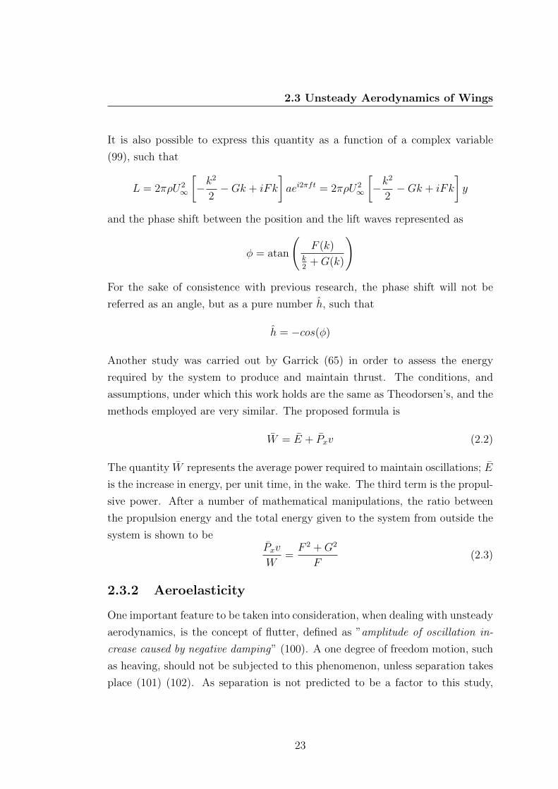
It is also possible to express this quantity as a function of a complex variable
(99), such that
L = 2πρU2∞
[−k
2
2−Gk + iFk
]aei2πft = 2πρU2
∞
[−k
2
2−Gk + iFk
]y
and the phase shift between the position and the lift waves represented as
φ = atan
(F (k)
k2
+G(k)
)
For the sake of consistence with previous research, the phase shift will not be
referred as an angle, but as a pure number h, such that
h = −cos(φ)
Another study was carried out by Garrick (65) in order to assess the energy
required by the system to produce and maintain thrust. The conditions, and
assumptions, under which this work holds are the same as Theodorsen’s, and the
methods employed are very similar. The proposed formula is
W = E + Pxv (2.2)
The quantity W represents the average power required to maintain oscillations; E
is the increase in energy, per unit time, in the wake. The third term is the propul-
sive power. After a number of mathematical manipulations, the ratio between
the propulsion energy and the total energy given to the system from outside the
system is shown to bePxv
W=F 2 +G2
F(2.3)
2.3.2 Aeroelasticity
One important feature to be taken into consideration, when dealing with unsteady
aerodynamics, is the concept of flutter, defined as ”amplitude of oscillation in-
crease caused by negative damping” (100). A one degree of freedom motion, such
as heaving, should not be subjected to this phenomenon, unless separation takes
place (101) (102). As separation is not predicted to be a factor to this study,
23

2. LITERATURE REVIEW
given the expected ride heights and angles of attack, flutter can be considered
not to be an issue. Conversely, static aeroelasticity has to be taken into account.
An aeroelastic analysis of the structure employed in this study will developed
from the examples presented by Hodges and Pierce (103).
The model can be considered to be a cantilever beam hinged to the top of the
wind tunnel, with the beam perpendicular to the flow. For a static condition, the
focus is on the deflection angle induced by the compliance of the structure, which
adds up to geometric angle of attack, and can induce failure of the structure,
if the moment induced by pitching becomes uncontrolled. The total deflection
angle is
θ = θF + θM
with
θF =F0 (2y)2
2EI; θM =
M0 (2y)
EI
with F0 and M0 being the horizontal force and the moment due to the strut
internal stiffness, if 2y is the total length of the strut. A further vertical force
introduced by the strut can be called R0. Horizontal balance gives only
D − F0 = 0 (2.4)
where D is the drag. Vertical balance yields
L+R0 +W = 0
with L being the lift, pointing upwards, and W being the weight. It is to be
noted how this equation does not contain any term including the deflection angle.
Momentum balance gives:
M0 − 2Wysinβ −Mac = 0 (2.5)
with β being the angle between the strut vertical and the line passing through
the hinge and the centre of mass. Mac is the moment due to aerodynamic forces.
Drag and moment appear in the previous equations. It is decided, given the low
overall incidence and the presence of ground effect, to assume the first as linear,
24
2.3 Unsteady Aerodynamics of Wings
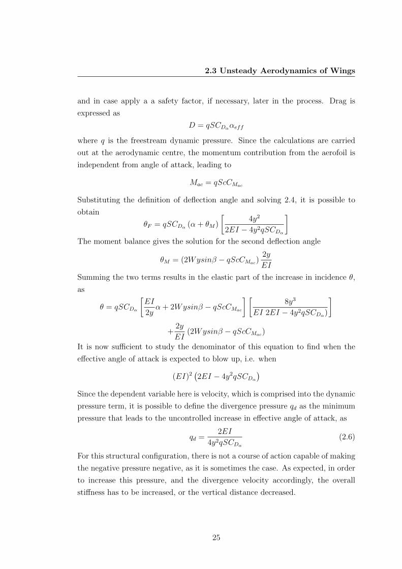
and in case apply a a safety factor, if necessary, later in the process. Drag is
expressed as
D = qSCDααeff
where q is the freestream dynamic pressure. Since the calculations are carried
out at the aerodynamic centre, the momentum contribution from the aerofoil is
independent from angle of attack, leading to
Mac = qScCMac
Substituting the definition of deflection angle and solving 2.4, it is possible to
obtain
θF = qSCDα (α + θM)
[4y2
2EI − 4y2qSCDα
]The moment balance gives the solution for the second deflection angle
θM = (2Wysinβ − qScCMac)2y
EI
Summing the two terms results in the elastic part of the increase in incidence θ,
as
θ = qSCDα
[EI
2yα + 2Wysinβ − qScCMac
] [8y3
EI 2EI − 4y2qSCDα)
]+
2y
EI(2Wysinβ − qScCMac)
It is now sufficient to study the denominator of this equation to find when the
effective angle of attack is expected to blow up, i.e. when
(EI)2(2EI − 4y2qSCDα
)Since the dependent variable here is velocity, which is comprised into the dynamic
pressure term, it is possible to define the divergence pressure qd as the minimum
pressure that leads to the uncontrolled increase in effective angle of attack, as
qd =2EI
4y2qSCDα(2.6)
For this structural configuration, there is not a course of action capable of making
the negative pressure negative, as it is sometimes the case. As expected, in order
to increase this pressure, and the divergence velocity accordingly, the overall
stiffness has to be increased, or the vertical distance decreased.
25
2. LITERATURE REVIEW
2.4 Combined Effect of Oscillations and Ground
Presence
The studies presented in the previous subsection cannot be fully applied to the
conditions of this study, since they lack in two fundamental features: ground
presence and Reynolds number. This last quantity is generally limited to 104 in
the best case, as a result of experimental constraints and researchers’ interest.
As proven by Isaac (104), the extrapolation of high Re results from low Re flows
would be completely inaccurate, as a consequence of the particular flow features
involved.
Indeed, the topic of an inverted wing in ground effect undergoing an oscillatory
motion has enjoyed little popularity: just a few articles exist. Some interest has
been displayed in the phenomenon of hysteresis, under which name fall all the
effects connected with the differences observed at a certain ground clearance de-
pending on the direction of approach, i.e. whether moving upwards or downwards.
It is to be remarked how this behaviour is different from an harmonic, oscillatory
motion, from both the standpoints of flow physics and aerodynamic loads. An
early study was carried out by Moryossef and Levi (105), using a one-equation
turbulence model coupled with a Euler/Navier-Stokes flow solver. It was found
that the average downforce was very close to the static value at the same ground
clearance, whereas the amplitudes of oscillation for both lift and drag increase as
the reduced frequency grows. Only the first mode is found to be important for
lift, whereas, for drag, higher modes (generally second and third) are of the same
order of magnitude of the first, and can not be neglected.
Two comprehensive articles have been published by Molina and Zhang (99) and
Molina et al. (106), investigating both the magnitude of lift and drag coeffi-
cients, and their behaviour in time with respect to the oscillatory motion. From
the point of view of lift, the proximity to the ground seems to yield more increase
in downforce at higher frequencies than at lower ones; furthermore, it is estab-
lished that if k < 1.09 the frequency variations do not have any tangible effect.
Thrust in freestream is said to be generated at k = 2.31, a value that rapidly
increases as the wing is brought close to the ground: at h/c = 0.33, the boundary
between drag and thrust is beyond k = 4. Peak forces are shown to increase as
26

2.4 Combined Effect of Oscillations and Ground Presence
reduced frequency increases and ground effect decreases. Peak to peak amplitude
increases as well, and for some conditions (provided k > 2) positive lift can be
produced in some parts of the cycle. Instantaneous switch from lift to drag can
take place at reduced frequencies as low as 0.34, with this value strongly depend-
ing upon the ride height.
Another parameter to be taken into account is the phase shift between motion
and downforce waves. This is influenced both by the initial position of the aero-
foil (its mean ground height) and the reduced frequency. Three main effects can
be isolated: ground presence, increased angle of attack and added mass; the last
two are already present in Theodorsen’s theory and account for the circulatory
and non-circulatory elements respectively.
At very low reduced frequencies, the flow can be considered quasi-stationary, and
the downforce generated at each position depends only on this quantity, as no
dynamic effects play a role; the boundary between quasi-stationary and unsteady
regions is set at k = 0.11. In this range of frequencies the ground presence is
therefore the only element that affects performance. As the reduced frequency is
increased, the velocity at the central point of the motion starts to be significant,
introducing an effective angle of attack, defined as
αeff = α0 + atan
[dhdt
U∞
](2.7)
The role of this increased angle of attack is to increase the lift of the wing, thus
moving the point of maximum downforce towards the centre of the motion, with
a null phase shift. The magnitude of maximum phase shift depends on both
reduced frequency and ride height: as the wing is moved closer to the ground, its
presence is more influential, therefore bringing the two waves closer and increasing
the reduced frequency at which this is reached. The limiting case is when the
motion occurs for the most part in the force reduction region, and the effect of
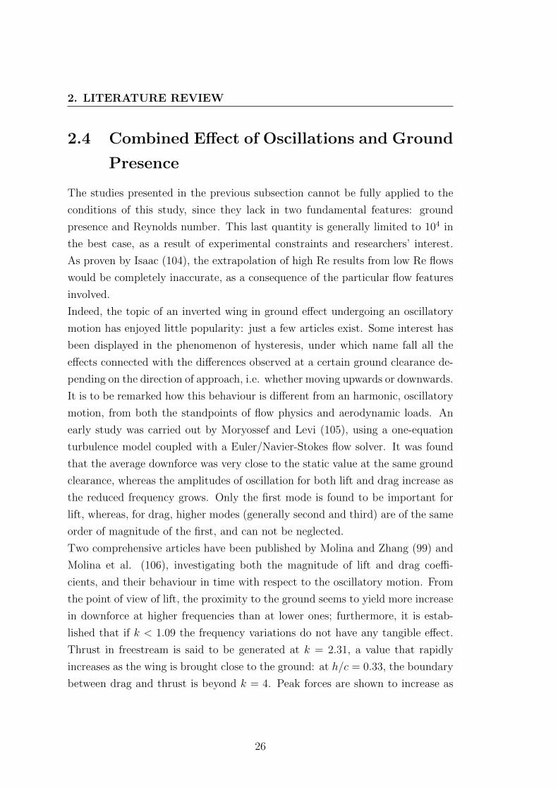
increased incidence induces a different shape in the h vs. k plot, as detailed in
figure 2.6. Since the presence of the α0 term in the previous equation, it is clear
that the geometrical characteristics of the wing, and its initial angle of attack,
can influence the effectiveness of the increased angle of attack phenomenon. As a
matter of fact, an α0 close to stall angle could trigger a separation-reattachment
27
2. LITERATURE REVIEW
Figure 2.6: Phase shift as a function of reduced frequencies at different ride
heights, from (99)
cycle different from free-stream, as the ground would both worsen the effect of
separation and reduce the effectiveness of the diffuser. As the reduced frequency
is further increased, an inviscid effect starts to move the phase shift back to 0,
and therefore the point of maximum downforce back to the lowest position of the
oscillatory motion, this time regardless of the initial ground height. The added
mass effect is related with the amount of fluid that has to be displaced by the wing
during its movement; the force generated by this phenomenon is proportional to
the acceleration of the wing, with the following law:
Fmass = ρθd2h
dt2(2.8)
Depending on the frequency, at the beginning of the upstroke a positive lift can
be experienced by the wing; in racing conditions, this would mean that the car
is highly unstable and almost impossible to drive. It is to be noted how this
phenomenon has the same effect on all the ride heights, meaning that all the
curves in Molina merge at a reduced frequency higher than 1.01.
28

3
Research Description
This chapter presents a description of the methods used in this research, including
the overall methodology, the relevant assumptions, an account of the model and
software used, as well as the initial programme for the wind tunnel testing. This
chapter is conceived as a series of information that can help understanding the
following one, and as a reference in case similar experiments are to be repeated.
3.1 General Approach
It has already been mentioned how, to the best knowledge of the author, this is
one the first experimental studies of a heaving wing in ground effect at a Reynolds
number in the order of 105. A careful planification is therefore highly necessary,
as well as a clear definition of the objectives.
As customary with experimental testing, the first variable to consider was the
availability, and in second order the specifications, of a wind tunnel. The RJ
Mitchell wind tunnel at the University of Southampton features is commonly
used for motorsport, aeronautical and sport-related research, making this the
preferred choice. The dimensions and principal characteristics of this facility are
described later in this same chapter. Once this is settled, the actual model to
be employed has to be decided. Contemporary F1 front wings are extremely
refined, and feature an incredible numbers of flaps, appendages and other micro-
aerodynamic devices. Beside the obvious manufacturing complication of building
such a model, two main problems exist: the first is to actually get a blueprint for
29

3. RESEARCH DESCRIPTION
such a component, and the second is to eventually discern the main factors that
influence performance. As a consequence, a simple single-element wing model
was used, for which static experimental validation (for the stationary case) and
computational validation for dynamic cases, is available in literature. The rela-
tive simplicity of this model makes possible to eliminate non-fundamental flow
features and force behaviours, and to concentrate only on the desired variables.
The validation data available constitute the baseline cases as well, to which the
following results are to be compared, when possible. The selection of the model
allows to design all the relevant components that need to transmit the alternate
motion to the motor to the wing, transforming it into a linear, vertical, displace-
ment. The role of this structure is also to ensure the required rigidity and stiffness
at design conditions.
The last part of this preliminary analysis is to determine what are the quanti-
ties to be analysed. As flow visualization techniques are not available, the focus
is shifted on the investigation of drag and lift principally, and their dynamic
behaviour. The independent variables to be changed are four: ground height,
wind speed, motion amplitude and motion frequency; these, in turn, define other
non-dimensional parameters such as reduced frequency, Reynolds number and
Strouhal number. The actual test programme is presented in the next subsec-
tion.
3.2 Test Programme
The test programme was prepared bearing in mind that one of the principal ob-
jectives was to reach a reduced frequency as high as possible, which can be done
by varying two quantities: wind speed and motion frequency. In particular, an
increase in frequency and a decrease in speed will obtain the same net change.
Both the quantities are indeed limited by practical constraints: the motor needs
a finite amount of time to invert its motion, and the wind tunnel speed is only
constant throughout the entire cross-section at a determinate value. This latter
was placed at 5 m/s, which was is considered to be the lower operational limit of
the wind tunnel, where the maximum frequency that was possible to obtain from
the motor (with an amplitude of 10 mm) was of 5 Hz. These two restrictions,
30
3.2 Test Programme
along with the chord of the wing, limited the maximum attainable reduced fre-
quency to 0.73.
Another objective was to examine the influence of different parameters on lift and
drag: namely, the ride height, the Reynolds number (governed by the wind speed
only) and the motion frequency. It was therefore decided that a comprehensive
set of test was needed. The wind tunnel velocities spanned between 5 and 40 m/s,
with steps of 5 m/s, the ride heights went from the lowest allowed by geometric
constraints (0.45) to one almost in free-stream (1.35), with three intermediate
values to bridge the gap (0.60, 0.75 and 0.90). Once this grid had been created,
all the different speed/clearance configurations were explored at various motion
frequencies, from 1 to 5 Hz, with 1 Hz steps, thus creating a three-dimensional
matrix.
Additional tests were performed with a 2.2% Gurney flap fitted to the trailing
edge of the wing and a rough strip on the suction side, as already listed in the
relevant section. Only two motion frequencies (3 and 5 Hz) beside the static con-
figuration, were investigated. Moreover, at a fixed frequency of 3 Hz, the effect of
different amplitudes, and therefore different Strouhal numbers, was studied. The
angle of attack of the wing was kept constant at 0.5◦ for all the duration of the
experiments, since it was not possible to alter it, as the geometry of the motor
plate did not allow to design a structure that could implement a mechanism to
modify this quantity. Further details are presented where relevant in the next
chapter.
Once in the wind tunnel, after the initial static tests, it was decided to start from
the lowest speed and then build up to the higher ones. For every speed, data
for all the frequencies were sampled at a given ride height; after this, the ride
height was changed. Gurney flap and transition-fixed runs were performed after
the initial set of tests was completed. Repeatability tests were performed both
in the same day at different times, and at different days. The condition chosen
to perform these tests was at a wind speed of 10 m/s, frequency of 2 Hz and
lower ride height. Lift and drag coefficients were both with a ±1% boundary of
the initial measurement.
31
3. RESEARCH DESCRIPTION
3.3 Assumptions
As it always happens when dealing with physical components, the overall layout
of the experiment is just a model of the conditions that are to be analysed, and
some assumptions are made, in order for the experiment to be meaningful. In
particular, a number of assumptions are worth mentioning for this study, from
different point of views:
• The motion input was designed to be a sinusoidal wave. As obvious, this
means that the actual motion transmitted to the wing is the sum of very
small discrete movements of the motor, and it is not a perfect sinusoidal
wave; nonetheless, the frequency at which the motor transmits the motion is
at least two orders of magnitude higher than the motion to be transmitted,
which allows the wave to be treated as sinusoidal.
This assumptions also involves the hypothesis that the oscillatory motion in
a racing car is purely sinusoidal: although not exactly so, this is still a good
approximation that does not interfere with the validity of the outcome.
• Similarly, the sampling procedure is assumed to be continuous: the actual
sampling frequency (1000 Hz) is again much higher than the maximum
frequency of any physical feature the flow is expected to show.
• The impact of the plates, struts and stings on the flow characteristics around
the wing is assumed to be negligible. A great effort was made to isolate the
wing from external influences as much as possible, for example by stream-
lining the vertical struts and designing the horizontal ones far away from
the pressure side. It is here to be recalled that on racing cars pillars exist to
support the wing, and that in ground effect the most significant features are
due to the pressure distribution on the suction side, which is barely affected
by any structure above the wing. Therefore, the aerodynamic loads were
deemed to be solely a result of the wing interaction with the flow. Cali-
bration runs were carried out to assess the drag of the structure (without
the wing), assuming that the drag generated by it and by the wing were
actually independent, and therefore the system to be linear in these two
components.
32
3.3 Assumptions
• All the forces reported in this study were measured by an overhead bal-
ance, which has already been calibrated, and is habitually used for similar
configurations. This assumed that the structure is perfectly rigid. As a
consequence of the material used (carbon fibre is very anisotropic), the
structure is effectively rigid to vertical loads (lift), whereas cannot be con-
sidered completely as such when streamwise forces are taken into account.
Therefore, maximum care was taken to design mountings capable of re-
straining the rotation motion around the central joint, thus reducing the
degrees of freedom.
• From the point of view of applicability of this study to racing cars, a couple
of distinguo need to be made. First, the maximum Reynolds number en-
countered in race conditions are normally higher than what can be obtained
in a wind tunnel, for a number of reason, and are of the order of 106. Sec-
ond, the flow around a wing is influenced by the components downstream,
primarily the wheels. Despite these two differences, the results can be ex-
trapolated to have relevance for these practical conditions as well. At the
same time, the flow has a very low turbulence intensity, a conditions that
can cease to exist if the wake of a preceding car is present. Again, this is
a singular case that cannot be analysed in a wind tunnel, but is still worth
remembering.
3.3.1 Sources of Error
It is useful to also discuss the sources of error that could have affected
the accuracy of the tests. First of all, the Re was computed from the
wind speed, which has an intrinsic fluctuation due to the fan motion, of
±0.3 m/s. At the same time, the ground is supposed to move at wind
speed. Ground speed uncertainty was measured to be ±0.1 m/s. Besides,
the pressure transducers, from which the wind speed is measured, have an
accuracy of ±0.15%. As a consequence, the maximum discrepancy between
ground and wind speed, at 30 m/s, is ±0.45 m/s, and decreases at lower
speeds. Other sources of error include the measurement of the angle of
33
3. RESEARCH DESCRIPTION
attack, performed with an inclinometer with an accuracy of ±0.1◦. The ride
height was initially measured using a ruler, perpendicular to the ground,
with a resolution of 1 mm. Only the minimum ride height was measured,
and then all the other ground clearances were obtained by displacing the
wing, using the electric motor, by a known quantity. The resolution of the
motor is much better than the ruler, and will not me discussed, since the
inaccuracies due to it would be negligible. Since all the quantities were
measured through the overhead balance, the accuracy of this component
has to be taken into account as well. It is anyway postulated that this
represents only a small part of the total errors.
3.4 Experimental Setup
3.4.1 Wing Assembly
The tests wee performed on an untwisted, untapered single element rectangular
wing. The wing profile is derived from the main element of the front wing used in
the 1998 Tyrrel 026 Formula 1 car. This aerofoil was developed starting from a
NASA GA(W)-1 profile, type LS(1)-0413, in order to reduce the magnitude of the
wake, by changing the position of the suction point, which was moved upstream
(41). A finite trailing edge has been introduced as well. The wing used was the
test is an 80% model, with a chord of 233 mm and a span of 1100 mm, with a
corresponding aspect ratio close to 5. The model is hollow and made of carbon
fibre. This wing was used for testing in ground effect a number of times already,
and validation data is widely available. Specifically, since its first appearance
this profile has quickly become the reference for the niche of inverted wings for
motorsport applications, and the vast majority of research on this topic has been
carried out on it.
A 2.2% Gurney flap was added after the first round of wind tunnel runs; it
consisted of an L-shaped aluminium strip that was glued, on one side, to the
wing. An adhesive stripe covered with grit was subsequently added to induce
transition on the suction side, this being centred at 10% of the chord, and with
a width of 4% of the chord approximately. Two aluminium-made, 2-mm thick
34
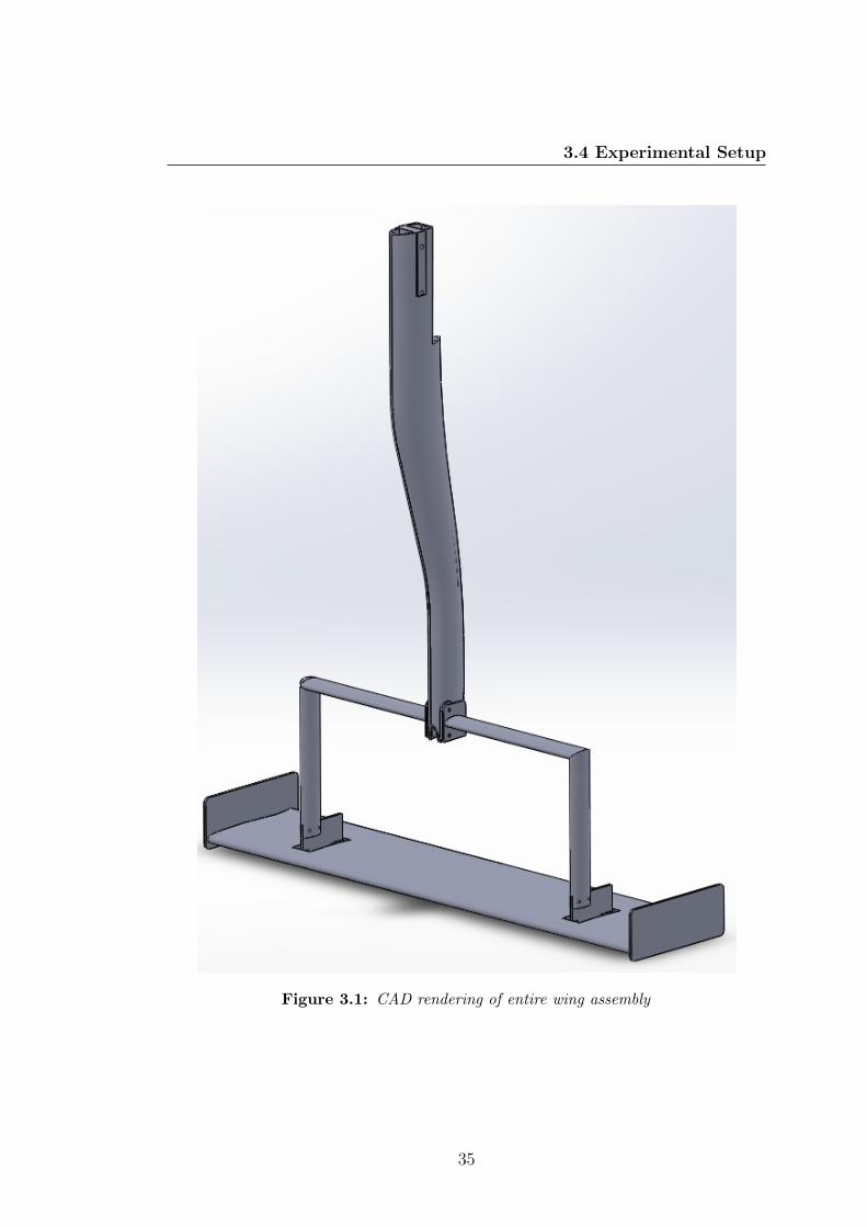
3.4 Experimental Setup
Figure 3.1: CAD rendering of entire wing assembly
35

3. RESEARCH DESCRIPTION
endplates were fitted at each end of the wing, with a length of 250 mm and a
height of 100 mm; the lower edge of the endplate was placed at 1 mm from the
lowest point of the suction side.
The existing parts were reverse-engineered and translated into a CAD file, from
which the mountings were developed: the connection between the horizontal
struts and the wing was designed to be performed using two aluminium plates,
bolted to the wing using two existing cavities on the pressure surface, at a distance
of 32% of the span from the centre point. These were connected through two
streamlined struts to a carbon fibre sting, which aim was to transmit the motion
from the motor to the wing. The cavities on the wing were covered with tape
during testing, to prevent any unwanted interaction with the incoming flow.
3.4.2 Wind Tunnel
Figure 3.2: Wing in the wind tunnel
All the tests were performed in the RJ Mitchell Wind Tunnel at the University
of Southampton, which has been already employed for industrial, motorsport
(Formula 1 and Indycar) and academic research. This wind tunnel features a
return circuit design and a closed test section, with cross-sectional dimensions of
36

3.4 Experimental Setup
3.6 x 2.5 m (11” x 8”). The test section is approximately 10.5 m long. On the
four corners of the testing section side fillets, with an angle of 45◦, are present.
The speed range of the wind tunnel is between 5 and 40 m/s, and the maximum
turbulence intensity, defined as
Tu =
√u′2
U∞
is of 0.2%. A moving ground is present, capable of velocities up to 40 m/s,
and with dimension of 4.0 x 1.9 m. A moving belt is the only known way to
correctly simulate real-life conditions and ground effect. The belt is made of
polyurethane and PVC, which makes is possible to keep a flat and predictable
road surface (107); lifting is avoided by means of suction under the belt. The
movement is transmitted by a roller system, which keeps the belt under tension
and in the right position in the middle of the test section. A separate cooling
system is employed to keep the belt temperature low, both for safety reasons and
in order not to change the test conditions. The wind tunnel itself is equipped
with a system to keep constant temperature in the test section. A double-staged
boundary layer removal device exists, with suction applied to small slots drilled
in an aluminium plate right upstream of the belt. The bulk of the incoming
boundary layer is removed by a forward-facing step placed further upstream,
which has incorporated suction. This boundary layer control allows a velocity
correspondent to 99.8% of free-stream at only 2 mm from the belt itself.
A 6-component balance is mounted above the test section and connected to the
wing through an ad hoc strut. The motion is generated by an electric motor,
already present in the wind tunnel, and connected to a eight-hole plate that
moves vertically. The motor is connected to a National Instruments chassis, that
can be controlled by a Labview programme. Specifically, the chassis is a PXI-
1044 model, and it is connected to the motor through a 3-axis PXI-7350 Motion
Controller port. The chassis also acquires the readings from the overhead balance,
through a PXI-4472 port.
37

3. RESEARCH DESCRIPTION
Figure 3.3: Example of task decomposition
3.4.3 Software
Two different softwares were employed in this study: Labview and Matlab. The
first one was used in situ to control the wing motion and acquire the desired data,
while the second was the preferred tool for data analysis. It is useful to present
a brief summary on their relevance in the tests.
As already mentioned, two main functionalities were needed in the wind tunnel:
motion control and data acquisition. This meant that a programme capable of
performing both tasks was needed. The approach followed in order to meet this
goal was the so-called functional decomposition (or top-down approach), which
is a standard in computer science: this involves breaking down big tasks into
smaller commands, and iterating this process until the basic instructions can be
easily written. The opposite process was carried out to build the entire software,
with the linkages between these constitutive parts being provided by the logic of
the software, that was conceived separately. In some sense, the entire procedure is
not dissimilar from the analysis-synthesis dichotomy, used throughout all fields of
science, and inspired by Descartes himself. An example of the first approach can
be found in figure 3.3, while the building process, along with the interface between
the two major software blocks, is visually represented in figure 3.4. Everything
was prepared with the objective of minimising human intervention and therefore
reducing the possibility of errors.
The actual data processing required the capability of handling massive amount
of data in an ordered, consistent and time-effective manner. The huge potential
38

3.4 Experimental Setup
of Matlab, which couples user-friendly interface and endless possibilities for plots
and figures with the potential of user-defined functions, made it the first choice
for this task. Since a number of manipulations was carried out on each file to
extract the relevant informations, an example of this procedure will be detailed
hereafter, in order to make next chapter more comprehensible to the reader.
1. The output file of the Labview programme is a .txt file with the various
columns representing the readings of the overhead balance. The first step
is therefore to isolate the sets of data that are to be examined later: the
output file is imported into Matlab using the built-in textscan function,
implemented into another ad hoc function. Three vectors are then obtained,
corresponding to the total vertical force, total horizontal force and vertical
position of the wing. This last value is important to compute the phase
shift between wing motion and lift generation, as detailed in the previous
chapter.
2. These vectors are then processed in order to obtain the steady part of the
measurement, for the static case, or the stable one for dynamic tests. This
involves applying a windowing procedure, that produces a coherent set of
data that can further manipulated later. Broadly speaking, the objective
is to get rid of the initial overshoot and correlated effects, and make sure
that the oscillations have taken place within certain boundaries. It is to
be noted how the settling period of the lift and drag signals was generally
lower than two cycles. This step produces two additional vectors, called Lift
and Drag, that can assume the required length, which cannot be, obviously,
higher than the original one.
3. It is then necessary to isolate the aerodynamic loads from the inertial effects.
The inertia force is computed from solid mechanics: for a sinusoidal motion
Finertia = mappk2Ax
where k is the frequency in Hz, A the amplitude in m , and x is the
normalised position of the wing (between -1 and 1). It is to be noted that the
39

3. RESEARCH DESCRIPTION
apparent mass was computed from runs carried out at no wind conditions,
and was different for all frequencies and amplitudes, since it did depend on
internal, non-linear resistances of the motor as well as the actual mass of the
components. Therefore, calibration runs for frequencies and amplitude were
carried out before the dynamic and wind-on tests. The actual accuracy of
this procedure was tested for freestream conditions at various frequencies,
comparing the results with what predicted by Theodorsen theory.
After the inertia is computed, a simple subtraction provides the actual
aerodynamic load, provided all the undesired effects are included into the
vector accounting for inertial effects. This step is needed for Lift only, as
the Drag vector is assumed to carry values due to the wing drag only, since
no horizontal motion takes place. The result is the Aero vector.
4. The Aero vector contains the values of the vertical aerodynamic load. It
is now possible to compute all the statistical quantities that are needed,
such as the average values meanlift and meandrag, as well as the motion
amplitudes peaklift and peakdrag.
5. At this point, a further step involves the interpolation of the Aero vector in
order to obtain an actual sinusoidal wave. This wave is then re-normalised
used the maximum value for the inertia vector, and then the phase shift
between the two waves is computed.
All these steps were unified in a single function, that needed as inputs only
the initial text file and the motion characteristics, and produced the mentioned
quantities, plus other that were used for other considerations. This highly au-
tomatised method has the potential to allow great flexibility in examining the
inter-dependence of different quantities.
40
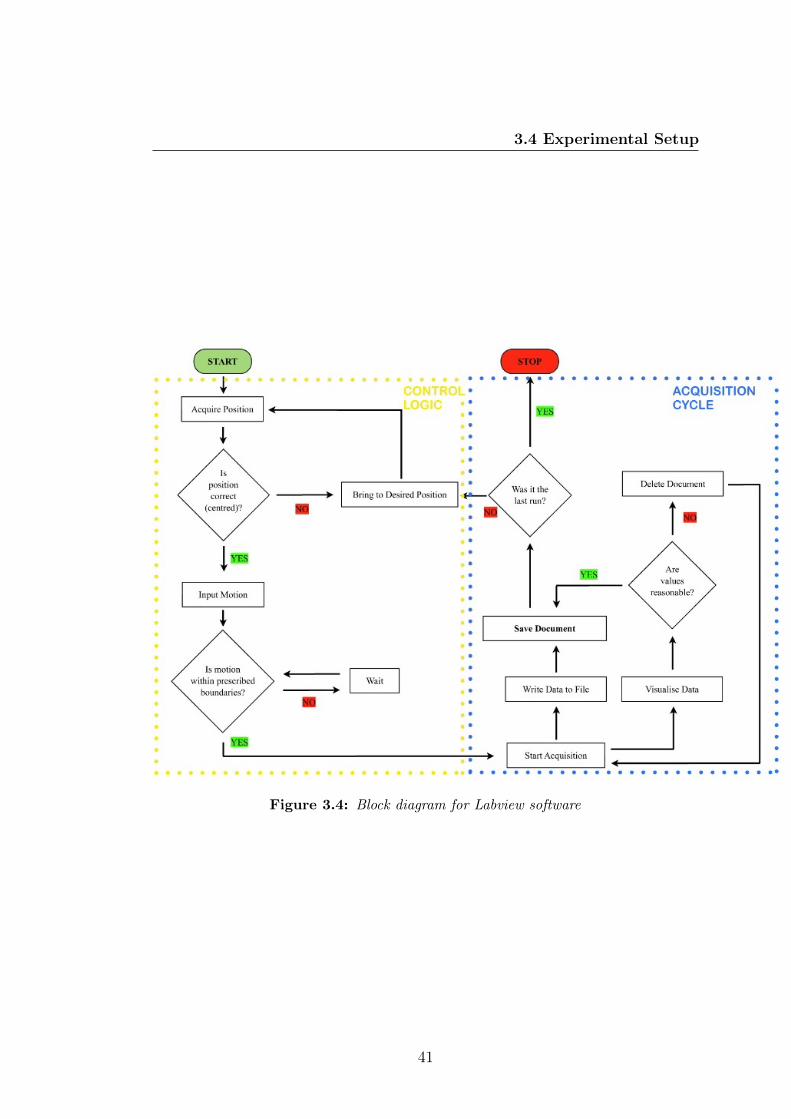
3.4 Experimental Setup
Figure 3.4: Block diagram for Labview software
41

3. RESEARCH DESCRIPTION
42

4
Results and Discussion
This chapter deals with the experimental results obtained in the wind tunnel. It
is to be stressed that more than 200 runs were carried out, with the independent
variables being altered as detailed in Chapter 3. After the data were processed,
the main results were selected and reported in this chapter, with the obvious or
non-relevant outcomes being neglected, for the sake of conciseness.
The preliminary results, used to validate the experimental set-up, in situ acqui-
sition and motion control software, and data processing technique are shown in
the first section. Next, the outcome of the main part of the experiments are
displayed. A brief account of the additional testing on Gurney flap influence and
transition fixing ensues.
4.1 Preliminary Study
As anticipated, a preliminary study was carried out in order to assess the suit-
ability of the experimental conditions to this case, and to prepare and verify the
Matlab functions that are required to extract the desired quantities, as detailed
in Chapter 3. It was not possible to employ the wing that has been used for the
subsequent tests, since the manufacturing process was not concluded yet. Instead,
a similar wing was mounted in the wind tunnel, with same profile but slightly
different dimensions; in any case, the purpose of this initial runs was not to find
values that could be compared with following data, but of appraising the capa-
bilities of the wind tunnel, motion and acquisition programmes, and overhead
43
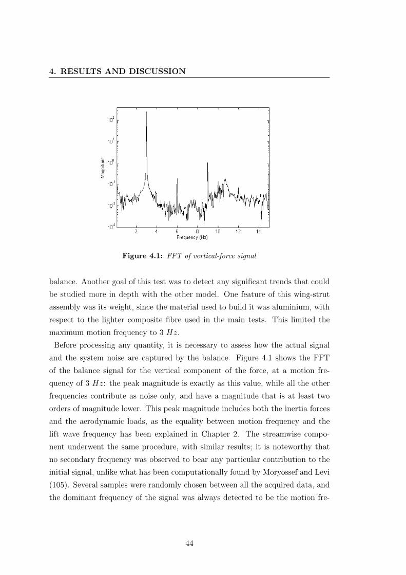
4. RESULTS AND DISCUSSION
Figure 4.1: FFT of vertical-force signal
balance. Another goal of this test was to detect any significant trends that could
be studied more in depth with the other model. One feature of this wing-strut
assembly was its weight, since the material used to build it was aluminium, with
respect to the lighter composite fibre used in the main tests. This limited the
maximum motion frequency to 3 Hz.
Before processing any quantity, it is necessary to assess how the actual signal
and the system noise are captured by the balance. Figure 4.1 shows the FFT
of the balance signal for the vertical component of the force, at a motion fre-
quency of 3 Hz: the peak magnitude is exactly as this value, while all the other
frequencies contribute as noise only, and have a magnitude that is at least two
orders of magnitude lower. This peak magnitude includes both the inertia forces
and the aerodynamic loads, as the equality between motion frequency and the
lift wave frequency has been explained in Chapter 2. The streamwise compo-
nent underwent the same procedure, with similar results; it is noteworthy that
no secondary frequency was observed to bear any particular contribution to the
initial signal, unlike what has been computationally found by Moryossef and Levi
(105). Several samples were randomly chosen between all the acquired data, and
the dominant frequency of the signal was always detected to be the motion fre-
44

4.1 Preliminary Study
Figure 4.2: Lift signal
quency, by a margin of at least an order of magnitude, two in most cases. Once it
was established that the signal was correctly captured by the overhead balance, it
was deemed as non necessary to perform this analysis for all signals, as it would
have been incredibly time-consuming. Since the order of magnitude of the forces
did not change throughout the entire study, and the frequencies were in the range
from 1 to 5 Hz, this is a reasonable conclusion.
The balance signal for lift can be observed in figure 4.2. As explained previously,
this reading comprises all the forces that are generated by the moving structure,
i.e. inertia and aerodynamic. The post-processing procedure for this signal has
been detailed in Chapter 3, but a couple of remarks need to be made. First, it
can be observed that the acquisition started before the motion, and ended after.
This was eventually made to measure any changes in the static values for lift and
drag immediately after the wing was stopped. Since no significant change was
observed, this approach was dropped after all ride heights were deemed not to be
influenced by previous history, in order to save time. Secondly, it is interesting to
see exactly how the analysed quantities were extracted from the original vectors,
as shown in figure 4.3. The initial reading is shown as Vertical Force. The inertial
force is then computed from the position of the wing and its apparent mass at a
45

4. RESULTS AND DISCUSSION
Figure 4.3: Example of lift signal post-processing
determined frequency (measured in the no-wind runs), as detailed in the previ-
ous chapter. A simple subtraction gives the aerodynamic load. The Interpolated
Aerodynamic Load curve is obtain either by means of simple interpolations (with
an ad hoc function) or by ensemble averaging, this last used as a confirmation.
Last, this curve is normalised by centring it at 0 and rescaling it to the same
amplitude of inertial force. This is only an intermediate step used to measure the
phase shift between the two curves. Once this value is known in time, it is enough
to know the frequency for the value of h can be computed. The only passage that
needs validation is when the aerodynamic load is obtained, as explained later in
this section. It was also decided to investigate the dependence of lift and drag
coefficients on speed, as shown in figure 4.4, in order to check that the correct
gain factors and calibrations were made by the programme. The expected trends
are recognised, with both the quantities depending in different measure on wind
speed: the lift changes marginally, whereas the drag notably diminishes. The
technique used to obtain the lift from the initial measurement has been detailed
already, and is based on strong arguments. Nonetheless, validating these results
could further reaffirm the correctness of this method. Theodorsen’s theory was
used for this purpose, as the expectations were to see a good agreement between
theoretical predictions and experimental measurements, both in trends and val-
ues. The phase shift can be observed in figure 4.5, and good concordance is
found: the experimental values seem moved to the right by a small distance, and
46
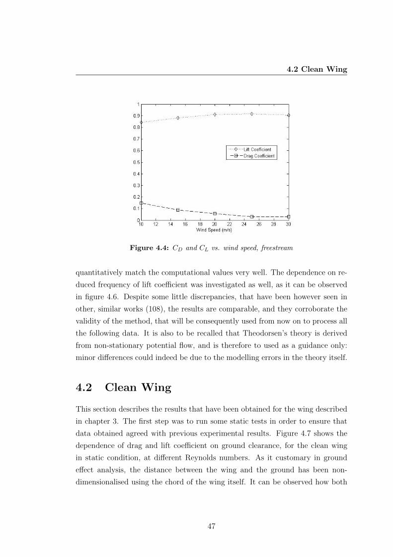
4.2 Clean Wing
Figure 4.4: CD and CL vs. wind speed, freestream
quantitatively match the computational values very well. The dependence on re-
duced frequency of lift coefficient was investigated as well, as it can be observed
in figure 4.6. Despite some little discrepancies, that have been however seen in
other, similar works (108), the results are comparable, and they corroborate the
validity of the method, that will be consequently used from now on to process all
the following data. It is also to be recalled that Theodorsen’s theory is derived
from non-stationary potential flow, and is therefore to used as a guidance only:
minor differences could indeed be due to the modelling errors in the theory itself.
4.2 Clean Wing
This section describes the results that have been obtained for the wing described
in chapter 3. The first step was to run some static tests in order to ensure that
data obtained agreed with previous experimental results. Figure 4.7 shows the
dependence of drag and lift coefficient on ground clearance, for the clean wing
in static condition, at different Reynolds numbers. As it customary in ground
effect analysis, the distance between the wing and the ground has been non-
dimensionalised using the chord of the wing itself. It can be observed how both
47

4. RESULTS AND DISCUSSION
Figure 4.5: Phase shift between lift and motion, comparison between experimental
and computed values
Figure 4.6: Lift coefficient, comparison between experimental and computed values
the coefficients show the known behaviour, i.e. they increase noticeably, with the
drag showing a steeper slope as it approaches lower heights. The actual mag-
nitudes of the two coefficients are very close, if not matching perfectly, existing
48

4.2 Clean Wing
Figure 4.7: Lift and drag coefficients vs. ground clearance
values for the same wing (41). The increase in lift is due to the Venturi-like effect
in particular, while the higher drag is due to induced effects mainly. It is here
worth mentioning that the actual figures for drag have been corrected already,
with the drag generated by the bodies in the wind tunnel being subtracted by
the balance reading, in order to derive the drag produced by the wing only. From
a ground clearance point of view, it was unfortunately not possible to enter the
force-reduction zone, as a consequence of the geometrical constraints in the as-
sembly itself. It is also interesting to show that the overall efficiency drops for
all cases when the wing approaches the ground (figure 4.8). Reynolds number
dependence is consistent with what is generally found in literature: an increase of
this parameter is matched by a slight reduction in both coefficients, and induces
a small benefit as efficiency is concerned, at least for the range of ride heights
here investigated. The differences encountered by changing Re are believed to be
a consequence of the different size and position of the separation bubble on the
suction surface.
Once the actual accuracy of the experimental layout was assessed, the focus was
shifted on the dynamic behaviour. The experimental plan was prepared in a
way that could allow to investigate the effect of three different quantities on
a given value, chiefly lift or drag; mathematically speaking, this means having
three independent variables (namely motion frequency, Reynolds number and
49
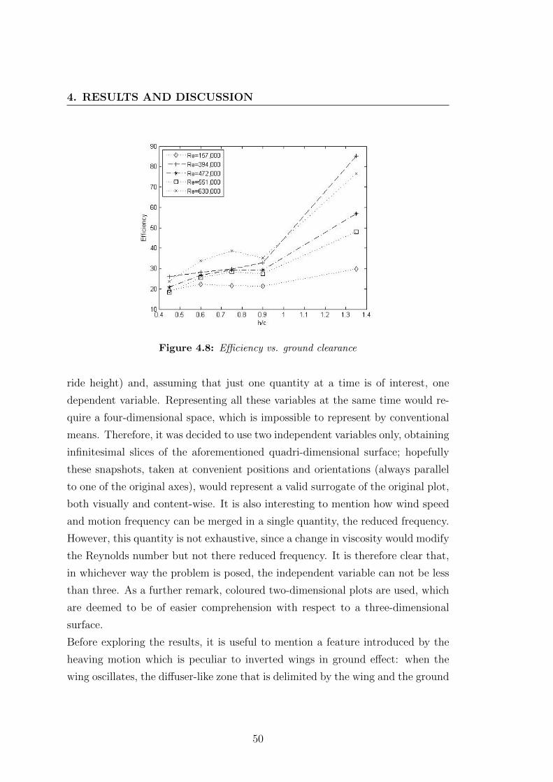
4. RESULTS AND DISCUSSION
Figure 4.8: Efficiency vs. ground clearance
ride height) and, assuming that just one quantity at a time is of interest, one
dependent variable. Representing all these variables at the same time would re-
quire a four-dimensional space, which is impossible to represent by conventional
means. Therefore, it was decided to use two independent variables only, obtaining
infinitesimal slices of the aforementioned quadri-dimensional surface; hopefully
these snapshots, taken at convenient positions and orientations (always parallel
to one of the original axes), would represent a valid surrogate of the original plot,
both visually and content-wise. It is also interesting to mention how wind speed
and motion frequency can be merged in a single quantity, the reduced frequency.
However, this quantity is not exhaustive, since a change in viscosity would modify
the Reynolds number but not there reduced frequency. It is therefore clear that,
in whichever way the problem is posed, the independent variable can not be less
than three. As a further remark, coloured two-dimensional plots are used, which
are deemed to be of easier comprehension with respect to a three-dimensional
surface.
Before exploring the results, it is useful to mention a feature introduced by the
heaving motion which is peculiar to inverted wings in ground effect: when the
wing oscillates, the diffuser-like zone that is delimited by the wing and the ground
50
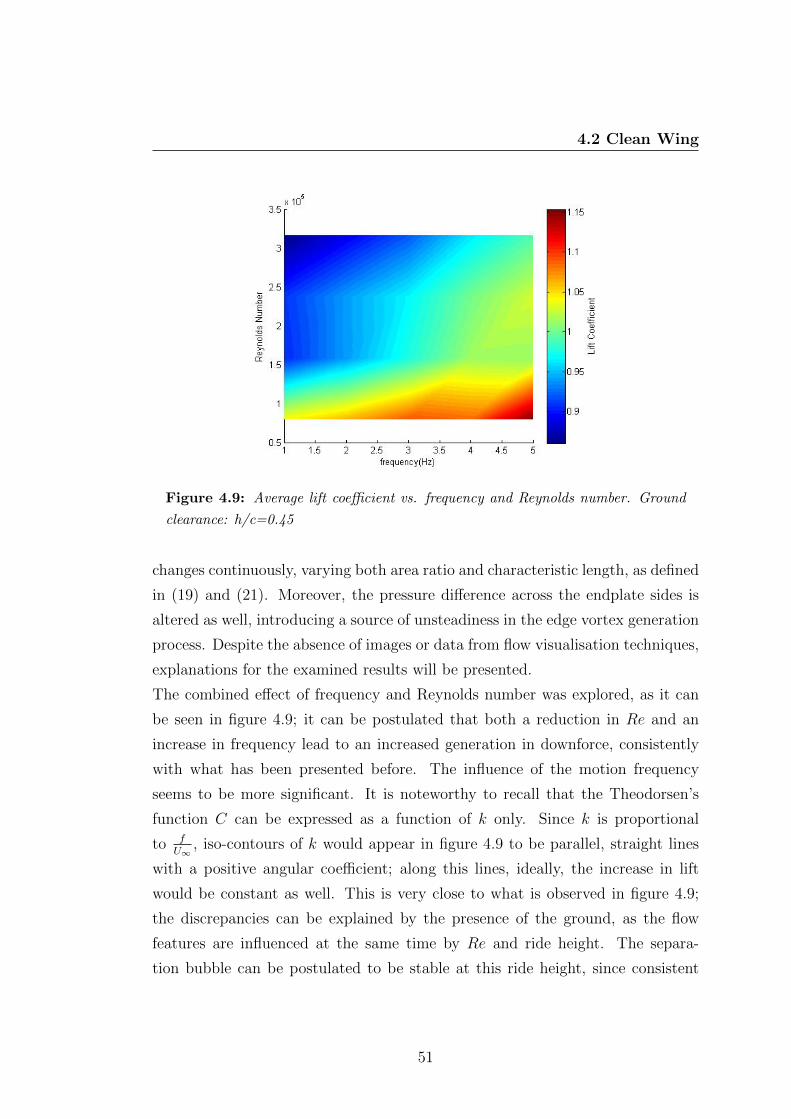
4.2 Clean Wing
Figure 4.9: Average lift coefficient vs. frequency and Reynolds number. Ground
clearance: h/c=0.45
changes continuously, varying both area ratio and characteristic length, as defined
in (19) and (21). Moreover, the pressure difference across the endplate sides is
altered as well, introducing a source of unsteadiness in the edge vortex generation
process. Despite the absence of images or data from flow visualisation techniques,
explanations for the examined results will be presented.
The combined effect of frequency and Reynolds number was explored, as it can
be seen in figure 4.9; it can be postulated that both a reduction in Re and an
increase in frequency lead to an increased generation in downforce, consistently
with what has been presented before. The influence of the motion frequency
seems to be more significant. It is noteworthy to recall that the Theodorsen’s
function C can be expressed as a function of k only. Since k is proportional
to fU∞
, iso-contours of k would appear in figure 4.9 to be parallel, straight lines
with a positive angular coefficient; along this lines, ideally, the increase in lift
would be constant as well. This is very close to what is observed in figure 4.9;
the discrepancies can be explained by the presence of the ground, as the flow
features are influenced at the same time by Re and ride height. The separa-
tion bubble can be postulated to be stable at this ride height, since consistent
51

4. RESULTS AND DISCUSSION
improvements are achieved. Apparently, the heaving motion is beneficial to the
development of this bubble, since higher improvements in downforce are obtained
at low Reynolds numbers. As the ride height is increased, the Reynolds number
effect becomes less important, and the heaving motion plays a more significant
role. At h/c = 1.35 the effects due to Re on lift generation are almost negligi-
ble if compared with the benefits deriving from the heaving motion. It is to be
noted that, if a larger angle of attack was reached, as a result of either a higher
geometric incidence or motion-induced effects, a higher Reynolds number could
help to prevent large-scale separation and maintain the lift at a pre-stall level.
On the other side, it is possible that in the force reduction zone an increased Re,
along with a higher motion frequency, could disrupt the beneficial flow features,
such as the edge vortex; as a consequence, the lift peak would take place further
away from the ground. Despite being an apparently negative result, this could
actually help when the ground height is fixed by regulations, if the minimum
allowed clearance is still in the force enhancement (or enhancement slowdown)
zone.
The drag coefficient shows a different behaviour, as it is almost negligibly affected
by the motion, and it is more significantly affected by the Reynolds number. The
plot almost represent an extension of the line seen for the line in figure 4.7, with
little to none frequency effects. As a matter of fact, the reduced frequencies here
are deemed to be too low to actually play a noticeable role. Indeed, as already
mentioned in literature (105), a low reduced frequency can actually increase the
drag, in close proximity to the ground. A similar behaviour was observed at
higher ride heights.
Subsequently, the combined effects of ground clearance and reduced frequency
is analysed, as shown in figure 4.11: the remarkable improvements prove how
these two variables can work together to increase downforce, consistently with
what observed before. At low Reynolds number the benefit seems to be higher in
free-stream, whereas at higher Re the improvement is larger for low ride heights.
It can be postulated that this behaviour is due to the different performance of
the diffuser-like effect, as a higher Re induces an improved lift coefficient at all
ride heights. Again, the ability of entering the force reduction zone could pro-
vide a valuable insight on the unsteady phenomena connected with this feature.
52

4.2 Clean Wing
Figure 4.10: Average drag coefficient vs. frequency and Reynolds number. Ground
clearance: h/c=0.45
The overall impact of reduced frequency seems to be more significant at a lower
Reynolds number, at most ride heights, also as a consequence of what previously
presented. For this particular testing configuration, in which the Re is defined
only by the wind speed (as chord, density and viscosity are almost constant), a
reduction in this variable would entail a higher effective angle of attack, at con-
stant motion frequency (see equation 2.5). Moreover, the benefits at a position
closer to the ground, at Re = 448, 00, are slightly higher than what it would be
expected from Theodorsen’s theory. Again, a beneficial interaction between the
ground effect and the heaving motion is detected.
The phase shift was measured as well, and it is presented in figure 4.12, showing
again good agreement with known computational data. The point of maximum
downforce moves to the centre point of the motion as the reduced frequency is
increased. After a maximum, that is reached at a value depending on the ground
clearance, the maximum downforce tends to be generated again closer to the
ground, as a consequence of the added mass effect.
Amplitude effects on the phase shift were investigated as well, at fixed frequency
and ground height. From figure 4.13, it can be observed that the trend, at a given
53

4. RESULTS AND DISCUSSION
Figure 4.11: Average lift coefficient vs. reduced frequency and ride height.
Reynolds number: 79,000 (left), 448,000 (right)
reduced frequency, is increasing as the amplitude is enlarged, regardless of the
frequency: this is postulated to happen as a result of the increased angle of attack
at the mid-point: in fact, αeff depends on the velocity as shown in equation 2.5
αeff = α0 + atan
[dhdt
U∞
](4.1)
For an harmonic sinusoidal oscillation, velocity can be expressed as
dh
dt= x(t) = afcos(ft) (4.2)
From 4.1 and 4.2
αeff = α0 + atan
[afcos(ft)
U∞
]which entails that the effective angle of attack is maximum for cos(ωt) = 1
(central point of oscillations) and equal to the geometrical one for cos(ωt) =
0 (extrema of oscillation). It is possible to plug in the definition of reduced
frequency k = πfcU∞
to obtain
αeff = α0 + atan
[akcos(ft)
πc
](4.3)
thus introducing a direct dependence on reduced frequency, at least for a sinu-
soidal motion; it is possible to reproduce this derivation every time the motion
54

4.2 Clean Wing
Figure 4.12: Phase shift vs. reduced frequency, h/c=0.45
can be defined as a continuous function. It is also to notice how the introduction
of a new variable, namely
h =a
c
could non-dimensionalise the motion amplitude with respect to the chord, in order
to obtain a further similarity parameter. The behaviour in 4.13 can be explained
from 4.3, as the phase shift is dependent on reduced frequency, at least in the
range of k were the increased angle of attack is expected to play a significant role.
Moreover, an increment in the maximum amplitude shows an analogous response;
both are non-linear effects since the presence of the trigonometric function.
The effective angle of attack at a given position can be derived by knowing the
quantitykh
π
which is just a rescaling of the Strouhal number. It would be anyway inaccurate
to use only this parameter to compute the phase shift, as the added mass effect
has a different dependence. From 2.6
Fmass = ρθd2h
dt2
55

4. RESULTS AND DISCUSSION
Figure 4.13: Phase shift vs. motion amplitude
In a similar fashiond2h
dt2= x(t) = −af 2sin(ft)
and
Fmass = −ρθaf 2sin(ft)
Following these steps, the expression for the added mass force is found, depend-
ing only on the known parameters ρθaf 2. If the reduced frequency and non-
dimensional amplitude are introduced
Fmass = −ρθ hkU∞fπ
sin(ft)
It is clear that the added mass effect cannot be derived from non-dimensional
parameters only, but that some other quantities need to be known as well.
4.3 Gurney Flap
As additional tests, it was decided to fit the wing with a Gurney flap placed on
the trailing edge. The dimension of the flap was approximately 2.2% of the chord,
56
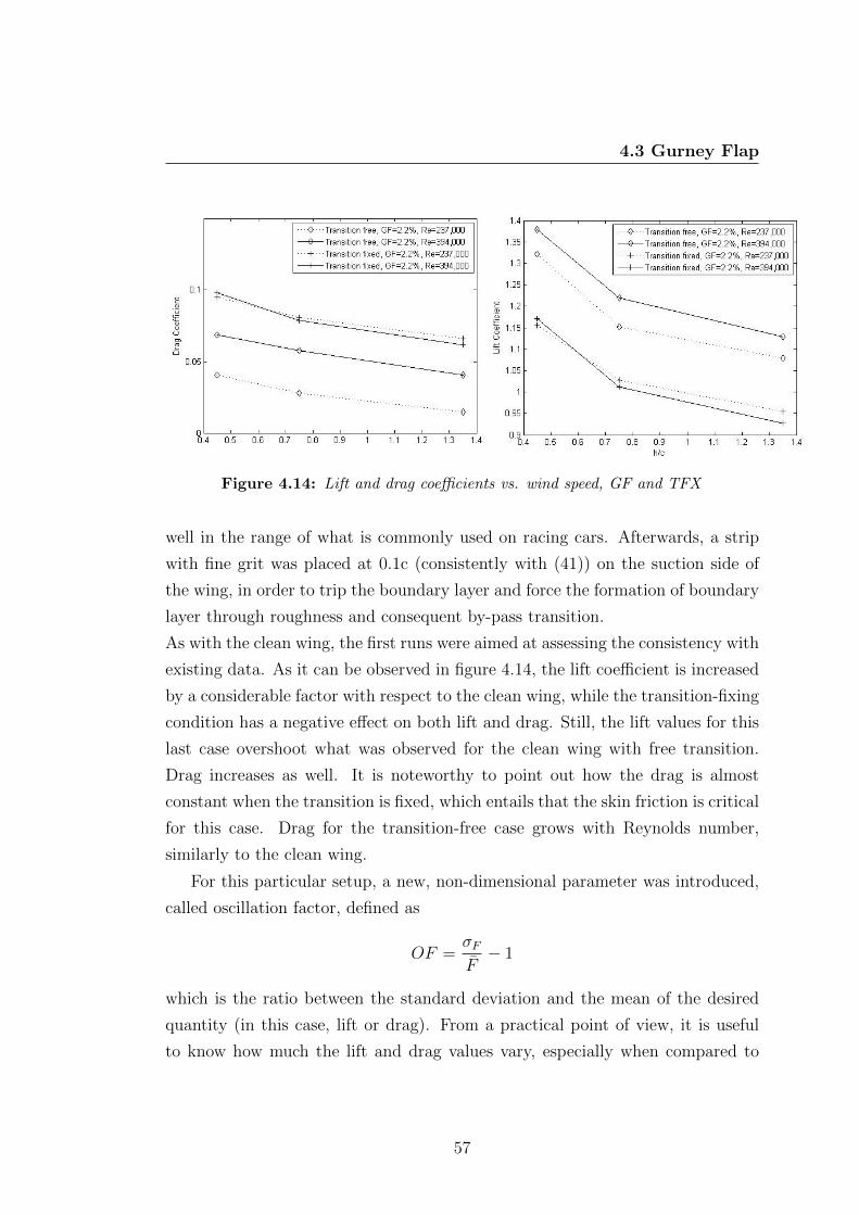
4.3 Gurney Flap
Figure 4.14: Lift and drag coefficients vs. wind speed, GF and TFX
well in the range of what is commonly used on racing cars. Afterwards, a strip
with fine grit was placed at 0.1c (consistently with (41)) on the suction side of
the wing, in order to trip the boundary layer and force the formation of boundary
layer through roughness and consequent by-pass transition.
As with the clean wing, the first runs were aimed at assessing the consistency with
existing data. As it can be observed in figure 4.14, the lift coefficient is increased
by a considerable factor with respect to the clean wing, while the transition-fixing
condition has a negative effect on both lift and drag. Still, the lift values for this
last case overshoot what was observed for the clean wing with free transition.
Drag increases as well. It is noteworthy to point out how the drag is almost
constant when the transition is fixed, which entails that the skin friction is critical
for this case. Drag for the transition-free case grows with Reynolds number,
similarly to the clean wing.
For this particular setup, a new, non-dimensional parameter was introduced,
called oscillation factor, defined as
OF =σFF− 1
which is the ratio between the standard deviation and the mean of the desired
quantity (in this case, lift or drag). From a practical point of view, it is useful
to know how much the lift and drag values vary, especially when compared to
57
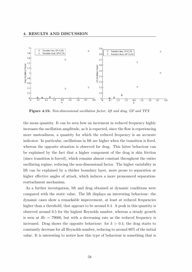
4. RESULTS AND DISCUSSION
Figure 4.15: Non-dimensional oscillation factor, lift and drag, GF and TFX
the mean quantity. It can be seen how an increment in reduced frequency highly
increases the oscillation amplitude, as it is expected, since the flow is experiencing
more unsteadiness, a quantity for which the reduced frequency is an accurate
indicator. In particular, oscillations in lift are higher when the transition is fixed,
whereas the opposite situation is observed for drag. This latter behaviour can
be explained by the fact that a higher component of the drag is skin friction
(since transition is forced), which remains almost constant throughout the entire
oscillating regime, reducing the non-dimensional factor. The higher variability in
lift can be explained by a thicker boundary layer, more prone to separation at
higher effective angles of attack, which induces a more pronounced separation-
reattachment mechanism.
As a further investigation, lift and drag obtained at dynamic conditions were
compared with the static value. The lift displays an interesting behaviour: the
dynamic cases show a remarkable improvement, at least at reduced frequencies
higher than a threshold, that appears to be around 0.4. A peak in this quantity is
observed around 0.5 for the highest Reynolds number, whereas a steady growth
is seen at Re = 79000, but with a decreasing rate as the reduced frequency is
increased. Drag shows the opposite behaviour: for k > 0.4, the drag starts to
constantly decrease for all Reynolds number, reducing to around 80% of the initial
value. It is interesting to notice how this type of behaviour is something that is
58

4.3 Gurney Flap
Figure 4.16: Non-dimensional lift and drag vs. reduced frequency, GF and TFX
encountered at higher reduced frequencies for a clean wing, which would suggest
that the addition of a Gurney flap can be considered, in some sense, similar to
an increase in reduced frequency. It is to be remembered that the wake of a
wing equipped with a Gurney flap features a discrete vortex shedding in static
conditions already. The reduction in drag can be explained with the different
alignment of shed vortices when an oscillatory motion is applied, a situation that
does not take place with the clean wing at reduced frequencies below 1. The
role of the Gurney flap in this drag reduction is therefore indirect, as it is simply
needed to trigger the vortex shedding in the wake. It is indeed more complicated
to explain the increase in lift; it can be postulated that the pressure difference
at the trailing edge is increased by the oscillatory motion, thus inducing a higher
base suction.
Figure 4.17 shows the phase shift for all the three main cases considered, at a
constant ride height h/c = 0.45 . It is observed that the peak is both anticipated
and increased, as the increased angle of attack plays a more prominent role at
a lower reduced frequency: the presence of Gurney flap induces a higher lift as
the effective incidence grows. The slope is also steeper, for the same reason.
The presence of transition fixing can introduce separation at the trailing edge,
introducing new flow features in this zone, especially if the presence of the Gurney
flap is considered. As a consequence, at low reduced frequencies the behaviour
59
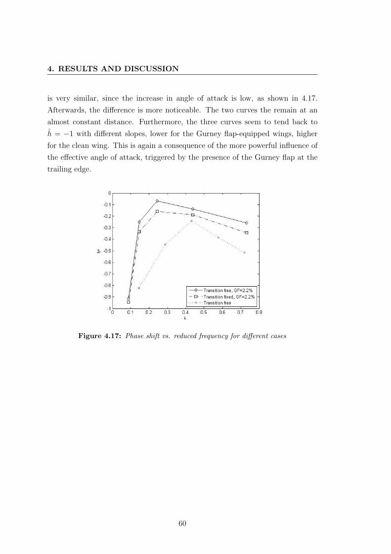
4. RESULTS AND DISCUSSION
is very similar, since the increase in angle of attack is low, as shown in 4.17.
Afterwards, the difference is more noticeable. The two curves the remain at an
almost constant distance. Furthermore, the three curves seem to tend back to
h = −1 with different slopes, lower for the Gurney flap-equipped wings, higher
for the clean wing. This is again a consequence of the more powerful influence of
the effective angle of attack, triggered by the presence of the Gurney flap at the
trailing edge.
Figure 4.17: Phase shift vs. reduced frequency for different cases
60

5
Conclusions and Further Work
The present study falls in the line of a research sector aimed at shedding light on
the possible improvements attainable by introducing unsteady flow features, by
means of externally-actuated motion on a lifting surface, such as a wing. Specifi-
cally, the focus of the project was to assess the suitability of wind tunnel testing to
the case of a planar, rectangular wing in heaving motion, at Reynolds numbers in
the order of 105. Subsequently, to investigate the influence of ground presence on
the aerodynamic loads produced by the wing itself, at different Reynolds number,
frequencies and wind speeds, with particular reference to the available literature.
A model capable of carrying the predicted loads has been designed and built, as
shown in Chapter 3. The preliminary tests, aimed at appraising the suitability of
the available facilities, have been undertaken as a necessary step towards the com-
pletion of the project. In particular, lift measurements for a wing in freestream
conditions were compared with what is predicted by the Theodorsen theory, in
order to validate the procedure that has been followed in the following tests.
Good agreement was found between the two sets of data, at least for the range of
reduced frequency that were permitted by the intrinsic limits posed by the avail-
able facilities, wind tunnel and electric motor in primis. It is worth mentioning
that one of the main constraints of wind tunnel testing for similar cases is the
upper boundary of reduced frequency, which is limited by the maximum motion
frequency that can be transmitted to the wing, and the minimum wind tunnel
speed at which a steady flow is obtained. These two technological bounds are
61
5. CONCLUSIONS AND FURTHER WORK
remarkably difficult to overcome, especially if the importance of Reynolds num-
ber is considered: an hypothetically smaller, and therefore lighter, model would
allow for higher frequencies to be reached; however, this would mean lowering the
Reynolds number. As a matter of fact, the trade-off between these two quantities
is something to be carefully considered when preparing a test programme, or even
defining project objectives.
An important step of the project was to assess the suitability of the selected wind
tunnel for this type of research, by comparing the theoretical values predicted by
Theodorsen’s theory with the experimental results. Once this was done, it was
possible to move the wing closer to the ground, in order to investigate ground
influence. The relative influence of three quantities on lift and drag coefficients
was studied: Reynolds number, ride height and reduced frequency. It was found
that all variables can play a significant role, and their combined influence was
assessed as well. The magnitude of force fluctuations is found to be qualitatively
similar to what was observed with CFD; the phase shift showed good agreement
as well. The dependence of the effective angle of attack on the Strouhal number
was demonstrated. Additional tests were performed on the same wing, adding a
Gurney flap at first, and then placing a rough strip on the suction side to trip
the boundary layer. The maximum phase shift (expressed as h) was observed to
increase, while the reduced frequency at which it occurs decreased. A beneficial
effect of increasing the reduced frequency was discovered on both lift and drag, as
a consequence of the vortex shedding introduced by Gurney flap presence even at
k < 1. The maximum oscillation in lift and drag was observed to be dependent
on reduced frequency too, as predicted.
Overall, the project proved the possibility of performing tests on non-stationary
wings at Re in the order of 105, and M in the order of 0.1. The calibration proce-
dure, to obtain the inertial forces, was validated against theoretical results. The
effectiveness of oscillatory motion to reduce drag is negligible, at least for k < 1,
as from existing literature. Conversely, it was first shown that the presence of a
Gurney flap, which induces significant vortex shedding even at very low frequen-
cies, can help to reduce drag and improve downforce, as the vortices respective
positions are modified by the wing motion, with respect to the static condi-
tions. The distribution of vorticity could lead to thrust characteristics at a much
62

lower value of reduced frequency than a clean wing. The contribution towards
downforce generation of the increased angle of attack effect grows in magnitude.
Similar trends, quantitatively less marked, are observed when the boundary layer
is tripped on the suction surface. In particular, a lower sensitivity to the effective
angle of attack and Reynolds number can be detected. Finally, from the results
of this investigation, improvements in aerodynamic efficiency and performance
in racing conditions are deemed as definitely possible; the study performed on
Gurney flap presence are particularly encouraging from this standpoint.
This research showed very promising result, especially for what concerns the
employment of experimental-based procedures for unsteady analysis, at a scale
significantly bigger than what is commonly employed. One of the limits, as men-
tioned, is the relatively low reduced frequency that can be achieved. To increase
this, the simplest method would be to have a higher motion frequency, which
could be attained with either a different motor or a lighter model. Covering up
to k = 3 would mean increasing the motion frequency to 15 Hz, at fixed chord
and wind speed. Another extension would be to build a model that could inves-
tigate lower ride heights, and eventually go as low as the force reduction zone.
Furthermore, a more comprehensive analysis of the influence of motion ampli-
tude would help to shed more light on the phenomenon. Eventually, the effect of
non-sinusoidal and even random oscillations is to be taken into consideration.
This project, for the most part, considered the effect of oscillatory motion and
ground presence from the standpoint of two quantities, lift and drag. Employing
visualisation techniques to explore the flow features in the wake of the wing is
of primary importance, given the importance of vortex shedding for this partic-
ular case. Pressure measurements on the two wing surfaces would arguably be
helpful as well. From the point of view of actual results, further studies on the
contemporaneous effect of Gurney flap and oscillatory motion is surely required,
as it was observed to be very promising and carrying a lot of potential, as it could
result in a much improved aerodynamic efficiency with a very little mechanical
input from the outside. Further research would, ideally, include double-element
wings, or even more complex layouts, in order to approach actual F1 wings.
63

5. CONCLUSIONS AND FURTHER WORK
64
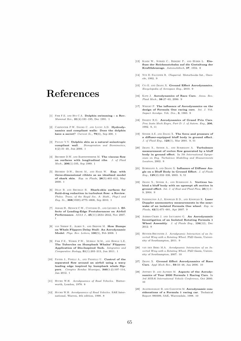
References
[1] Fish F.E. and Hui C.A. Dolphin swimming - a Rev.
Mammal Rev., 21(4):181–195, Dec 1991. 1
[2] Carpenter P.W. Davies C. and Lucey A.D. Hydrody-
namics and compliant walls: Does the dolphin
have a secret? Current Sc., 79(6), Sep 200. 1
[3] Pavlov V.V. Dolphin skin as a natural anisotropic
compliant wall. Bionspiration and Biomimetics,
1(2):31–40, Jun 2006. 1
[4] Bechert D.W. and Bartenwerfer M. The viscous flow
on surfaces with longitudinal ribs. J. of Fluid
Mech., 206(1):105, Sep 1989. 1
[5] Bechert D.W., Bruse M., and Hage W. Exp. with
three-dimensional riblets as an idealized model
of shark skin. Exp. in Fluids, 28(5):403–412, May
2000. 1
[6] Dean B. and Bhushan B. Shark-skin surfaces for
fluid-drag reduction in turbulent flow: a Review.
Philos. Trans. of the Royal Soc. A: Math., Phys.l and
Eng. Sc., 368(1929):4775–4806, Sep 2010. 1
[7] Johari H., Henoch C.W., Custodio D., and Levshin A. Ef-
fects of Leading-Edge Protuberances on Airfoil
Performance. AIAA J., 45(11):2634–2642, Nov 2007.
1
[8] van Nierop E., Alben S., and Brenne M. How Bumps
on Whale Flippers Delay Stall: An Aerodynamic
Model. Phys. Rev. Letters, 100(5), Feb 2008. 1
[9] Fish F.E., Weber P.W., Murray M.M., and Howle L.E.
The Tubercles on Humpback Whales’ Flippers:
Application of Bio-Inspired Tech. Integrative and
Comparative Biology, 51(1):203–213, Jun 2011. 1
[10] Favier J., Pinelli A., and Piomelli U. Control of the
separated flow around an airfoil using a wavy
leading edge inspired by humpback whale flip-
pers. Comptes Rendus Mcanique, 340(1-2):107–114,
Jan 2012. 1
[11] Hucho W.H. Aerodynamics of Road Vehicles. Butter-
worth, London, 1978. 8
[12] Hucho W.H. Aerodynamics of Road Vehicles. SAE Inter-
national, Warren, 4th edition, 1998. 8
[13] Kamm W., Schmid C., Riekert P., and Huber L. Ein-
fluss der Reichsautobahn auf die Gestaltung der
Kraftfahrzeuge. Automobiltech, 37, 1934. 8
[14] Nye D. Falconer R. Chaparral. Motorbooks Int., Osce-
ole, 1992. 9
[15] Cui E. and Zhang X. Ground Effect Aerodynamics.
Encyclopedia of Aerospace Eng., 2010. 9
[16] Katz J. Aerodynamics of Race Cars. Annu. Rev.
Fluid Mech., 38:27–63, 2996. 9
[17] Wright P. The influence of Aerodynamics on the
design of Formula One racing cars. Int. J. Veh.
Impact Aerodyn. Veh. Des., 3, 1983. 9
[18] Dominy R.G. Aerodynamics of Grand Prix Cars.
Proc Instn Mech Engrs, Part D: J. of Autom. Eng., 206,
1992. 9, 11
[19] Senior A.E. and Zhang X. The force and pressure of
a diffuser-equipped bluff body in ground effect.
J. of Fluid Eng., 123(1), Mar 2001. 9, 51
[20] Zhang X., Senior A., and Rurhmann A. Turbulence
measurement of vortex flow generated by a bluff
body in ground effect. In 5th International Sympo-
sium on Eng. Turbulence Modelling and Measurements
Location, 2002. 9
[21] Ruhrmann A. and Zhang X. Influence of Diffuser An-
gle on a Bluff Body in Ground Effect. J. of Fluids
Eng., 125(2):332–338, 2003. 9, 51
[22] Zhang X., Senior A., and Rurhmann A. Vortices be-
hind a bluff body with an upswept aft section in
ground effect. Int. J. of Heat and Fluid Flow, 25(1):1–
9, 2004. 9
[23] Saddington A.J., Knowles R D., and Knowles K. Laser
Doppler anemometry measurements in the near-
wake of an isolated Formula One wheel. Exp. in
Fluids, 42(5):671–681, Apr 2007. 9
[24] Axerio-Cilies J. and Iaccarino G. An Aerodynamic
Investigation of an Isolated Rotating Formula 1
Wheel Assembly. J. of Fluids Eng., 134(12), Dec
2012. 9
[25] Heyder-Bruckner J. Aerodynamic Interaction of an In-
verted Wing with a Rotating Wheel. PhD thesis, Univer-
sity of Southampton, 2011. 9
[26] van den Berg M.A. Aerodynamic Interaction of an In-
verted Wing with a Rotating Wheel. PhD thesis, Univer-
sity of Southampton, 2007. 10
[27] Zhang X. Ground Effect Aerodynamics of Race
Cars. Appl Mech Rev., 59:33–48, Jan 2006. 10
[28] Jeffrey D. and Alperin M. Aspects of the Aerody-
namics of Year 2000 Formula 1 Racing Cars. In
3rd MIRAl International Vehicle Conference, Oct 2000.
10
[29] Agathangelou B. and Gascoyne M. Aerodynamic con-
siderations of a Formula 1 racing car. Technical
Report 980399, SAE, Warrendale, 1998. 10
65
REFERENCES
[30] Zahm A.F. and Bear R.M. Ground-plane influence
on airplane wings. J. Franklin Inst, 191(5):687–693,
1921. 10
[31] Dominy J.A. and Dominy R.G. Aerodynamic influ-
ences on the performance of the Grand Prix rac-
ing car. Proc Instn Mech Engrs, Part D: J. of Autom.
Eng., 198:1–7, 1984. 11
[32] Katz J. Calculation of the aerodynamic forces on
automotive lifting surfaces. ASME J. Fluids Eng.,
107(4):438–443, 1985. 11
[33] Katz J. Aerodynamics of high-lift, low aspect-
ratio unswept wings. AIAA J., 27(8):1123–1124,
1989. 11
[34] Coulliette C. and Plotkin A. Aerofoil ground effect
revisited. Aeronaut. J., pages 65–74, 1996. 11
[35] Ranzenbach R. and Barlow J. B. Two-Dimensional
Airfoil in Ground Effect, An Experimental and
Computational Study. SAE Paper, 1(94-2509):241–
249. 11
[36] Ranzenbach R. and Barlow J. B. Cambered Airfoil
in Ground Effect: Wind tunnel and road condi-
tions. SAE Paper, 1(95-1909):269–276, Jun 1995. 11
[37] Ranzenbach R. and Barlow J. B. Cambered Airfoil
in Ground Effect - An Experimental and Com-
putational Study. SAE Paper, 1(96-0909):269–276.
11
[38] Diaz R. H. Ranzenbach R., Barlow J. B. Multi-Element
Airfoil in Ground Effect An Experimental and
Computational Study. AIAA Paper, (97-2238), Jun
1997. 11
[39] Knowles K., Donahue D. T., , and Finnis M. V. A Study
of Wings in Ground. In Loughborough University
Conference on Vehicle Aerodynamics, 1994. 11
[40] Neely A.J. Doig G, Barber T.J. The Influence of Com-
pressibility on the Aerodynamics of an Inverted
Wing in Ground Effect. J. Fluids Eng., 133(06110),
Jun 2011. 12
[41] Zerihan J. and Zhang X. Aerodynamics of a Single-
Element Wing- in-Ground Effect. J. of Aircraft,
37(6):1058–1064, 2000. 12, 14, 34, 49, 57
[42] Zhang X. and Zerihan J. Off-Surface Aerodynamic
Measurements of a Wing in Ground Effect. J. of
Aircraft, 40(4):716–725, Jul-Aug 2003. 12, 13
[43] Zhang X. and Zerihan J. Aerodynamics of a Double-
Element Wing in Ground Effect. AIAA J.,
41(6):1007–1016, Jun 2003. 12
[44] Zhang X. and Zerihan J. Edge Vortices of a Dou-
ble Element Wing in Ground Effect. J. of Aircraft,
41(5):1127–1137, Sep 2004. 12
[45] Mahon S. and Zhang X. Computational Analysis of
Pressure and Wake Characteristics of an Aero-
foil in Ground Effect. J. Fluids Eng., 127:289–297,
mar 2005. 12
[46] Mahon S. and Zhang X. Computational Analysis of a
Inverted Double-Element Airfoil in Ground Ef-
fect. J. Fluids Eng., 128. 12
[47] Soso M.D. and Wilson P.A. Aerodynamics of a wing
in ground effect in generic racing car wake flows.
Proc Instn Mech Engrs, Part D: J. of Autom. Eng., 220.
12
[48] Soso M.D. and Wilson P.A. The influence of an up-
stream diffuser on a downstream wing in ground
effect. Proc Instn Mech Engrs, Part D: J. of Autom.
Eng., 127. 12
[49] Zerihan J. An investigation into the aerodynamics of
wings in ground effect. PhD thesis, University of
Southampton, 2001. 13
[50] Galoul V. and Barber T.J. A study of and inverted
wing with endplates in ground effect. In 16th Aus-
tralasian Fluid Mech. Conference, Oct 2007. 13
[51] Jasinski W.J. and Selig M.S. Experimental Study of
Open-Wheel Race-Car Front Wings. SAE Paper,
Nov. 13
[52] Vogt J.W. and Barber T.J. Ground effect phenom-
ena about lift and downforce generating cam-
bered aerofoils. Int.l J. of Numerical Methods for Heat
& Fluid Flow, 22(2), 2012. 14
[53] Gruschwitz E. and Schrenk O. Uber eine Ein-
fache Moglichkeit zur Auftiebserhohung von
Tragugeln. Zeitschrift fur Flugtechnik und Motor-
luftschiffahrt, 20, Oct 1932. 14
[54] Duddy R.R. High Lift Devices and Their Uses. J.
of the Royal Aeronautical Soc., 53(465):859–900, 1949.
14
[55] Liebeck R.H. Design of Subsonic Airfoils for High
Lift. J. of Aircraft, 15(9):547–561, Sep 1978. 14
[56] Myose R., Papadakis M., and Heron I. Gurney Flap
Exp. on Airfoils, Wings, and Reflection Plane
Model. J. of Aircraft, 35(2):206–211, Mar 1998. 14
[57] Storms B.L. and Jang C.S. Lift enhancement of an
airfoil using a Gurney flap and vortex genera-
tors. J. of Aircraft, 31(3):542–547, May 1994. 14
[58] Jang C.S., Ross J.C., and Cummings R.M. Computa-
tional evaluation of an airfoil with a Gurney flap.
AIAA Paper, (92-2708), Jan 1992. 15
[59] Giguere P., Lemay J., , and G. Dumas. Gurney flap ef-
fects and scaling for low-speed airfoils. In 13th
Applied Aerodynamics Conference, Jun 1995. 15
[60] Jeffrey D., Zhang X., and Hurst D.W. Aerodynamics
of Gurney Flaps on a Single-Element High-Lift
Wing. J. of Aircraft, 37(2):295–301, Mar 2000. 15
[61] Jeffrey D., Zhang X., and Hurst D.W. Some As-
pects of the Aerodynamics of Gurney Flaps on a
Double-Element Wing. J. of Fluids Eng., 123(1):99,
2001. 15
66

REFERENCES
[62] Cole J.A., Vieira B.A.O., Coder J.G., Premi A., and
Maughmer M.D. Experimental Investigation into
the Effect of Gurney Flaps on Various Airfoils.
J. of Aircraft, 50(4):1287–1294, Jul 2013. 16
[63] Ellenrieder K. D. and Pothos S. PIV measurements
of the asymmetric wake of a two dimensional
heaving hydrofoil. Exp. in Fluids, 44(5):733–745,
May 2008. 16, 18
[64] Theodorsen T. General theory of aerodynamic in-
stability and the mechanism of flutter. (NACA
Tech Report 496), 1935. 17
[65] Garrick I.E. Propulsion of a flapping and oscil-
lating airfoil. (NACA Tech Report 567), 1937. 17,
23
[66] Knoller R. Die gesetze des luftwiderstandes. Flug-
und Motortechnik, 3:1–9, 1909. 17
[67] Betz A. Ein beitrag zur erklarung des segelfluges.
Z. Flugtech. Motorluftschiffahrt, 3:269–272, 1912. 17
[68] von Karman and Burgess J.M. General aerodynamic the-
ory: perfect fluids. Springer, 1935. 17
[69] Ohashi H. and Ishikawa N. Visualisation study of flow
near the trailing edge of an oscillating airfoil. Bul-
lettin of the Jap. Soc. of Mech. Eng., 15:840–845, 1972.
17
[70] Oshima T. and Oshima K. Vortical flow behind an
oscillating airfoil. In Proceedings of the 15th Interna-
tional Congress, Int. U. of Theor. and App. Mech., pages
357–368, 1980. 17
[71] Freymuth P. Propulsive vortical signature of
plunging and pitching airfoils. AIAA J., 26:8881–
883, 1988. 17
[72] Triantafyllou G.S., Triantafyllou M.S., and M.A.
Grosenbaugh. Optimal thrust development in os-
cillating foils with application to fish propulsion.
J. of Fluids and Structures, 7:205–224, 1993. 17
[73] Koochesfahani M. Vortical Patterns in the wake of
an oscillating airfoil. AIAA J., 27, 1989. 17
[74] Young J. and Lai J.C.S. Oscillation Frequency and
Amplitude Effects on the Wake of a Plunging
Airfoil. AIAA J., 42(10):2042–2052, Oct 2004. 17
[75] Lai J.C.S. and Platzer M.F. Jet Characteristics of a
Plunging Airfoil. AIAA J., 37(12):1529–1537, 1999.
17
[76] Triantafyllou M.S. and Grosenbaugh M.A. Prediction
of vortex-induced vibrations in sheared flows. In
6th International Conference on Flow-Induced Vibration,
pages 73–82, 1995. 17
[77] Streitlien J. and Triantafyllou G.S. On thrust esti-
mates for flapping foils. J. of Fluids and Structures,
12:47–55, 1998. 17
[78] Drucker G.E. and Lauder G.V. Locomotor function
of the dorsal fin in teleost fishes: experimental
analysis of wake forces in sunfish. J. Exp. Biol.,
204(17):2943–2958, 2001. 18
[79] Wolgang M.J., Amnderson J.M., Grosenbaugh M.A., Yue
D.K.P., and Triantafyllou M.S. Near-body flow dy-
namics in swimming fish. J. Exp. Biol., 202:2303–
2327, 1999. 18
[80] Godoy-Diana R., Aider J.-L., and Wesfreid J.E. Transi-
tions in the wake of a flapping foil. Physical Rev.
E, 77(1), Jan 2008. 18
[81] He G.-Y., Wang Q., Zhang X., and Zhang S.-G. Nu-
merical analysis on transitions and symmetry-
breaking in the wake of a flapping foil. Acta Me-
chanica Sinica, 28(6):1551–1556, Dec 2012. 18
[82] Lewin G.C. and Haj-Hariri H. Modelling thrust gen-
eration of a two-dimensional heaving airfoil in
a viscous flow. J. of Fluid Mech., 492:339–362, Oct
2003. 18
[83] Liang H., Zhou L., Zong Z., and Sun L. An analyti-
cal investigation of two-dimensional and three-
dimensional biplanes operating in the vicinity of
a free surface. J. of Mar. Sc. and Tech., 18(1):12–31,
Mar 2013. 18
[84] Shyy et al. Aerodynamics of Low Reynolds Number Fly-
ers. Cambridge Aerospace Series, 2008. 19
[85] McCroskey W.J. and Fisher R.K. Detailed aerody-
namic measurements on a model rotor in the
blade stall regime. J. Amer. Helic. Soc., 17:20–30,
1972. 19, 20
[86] Liu H. Simulation-based biological fluid dynamics
in animal locomotion. App. Mech. Rev., 58:269–282,
2005. 19
[87] Warrick D.R., Tobalske B.W., and D.R. Powers. Aero-
dynamics of the hovering hummingbird. Nature,
435:1094–1097, 2005. 19
[88] Usherwood J.R. and Ellington C.P. The aerodynam-
ics of revolving wings I. Model hawkmoth wings.
J. Exp. Biol., 205:1547–1564, 2002. 19
[89] Birch J.M. and Dickinson M.H. Spanwise flow and the
attachment of the leading-edge vortex on insect
wings. Nature, 412:729–733, 2001. 19
[90] Ashraf M. A., Young J., and Lai J.C.S. Oscillation Fre-
quency and Amplitude Effects on Plunging Air-
foil Propulsion and Flow Periodicity. AIAA J.,
50(11):2308–2324, Nov 2012. 19
[91] Medjroubi W., Stoevesandt B., Carmo B., and Peinke
J. High-order numerical simulations of the flow
around a heaving airfoil. Computers and Fluids,
51(1):68–84, Dec 2011. 19
[92] Kang C., Aono H., Sik Baik Y., Bernal L.P., and Shyy W.
Fluid Dynamics of Pitching and Plunging Flat
Plate at Intermediate Reynolds Numbers. AIAA
J., 51(2):315–329, Feb 2013. 20
67
REFERENCES
[93] Kramer M. Die Zunahme des Maximalauftriebes
von Tragflugeln bei plotzlicher Anstellwinkelver-
grosserung (Boeneffect). Zeitschrift fur Flugtechnik
und Motorluftschiffahrt, 27(7):185–189, 1932. 20
[94] Dickinson M.H., Lehmann F.-O., and Sane S.P. Wing ro-
tation and the aerodynamic basis of insect flight.
Sc., 284:1954–1960, 1999. 21
[95] Sunada S. and Ellington C.P. Approximate added-
mass method for estimationg induced power for
flapping fightt. AIAA J., 38:1313–1321, 2000. 21
[96] Andro J.-Y. and Jacquin L. Frequency effects on the
aerodynamic mechanisms of a heaving airfoil in
a forward flight configuration. Aerospace Sc. and
Tech., 13(1):71–80, Jan 2009. 21
[97] Yu M., Wang Z.J., and Hu H. Airfoil Thickness Effects
on the Thrust Generation of Plunging Airfoils. J.
of Aircraft, 49(5):1434–1439, Sep 2012. 21
[98] Brunton S.L. and Rowley C.W. Empirical state-space
representations for Theodorsen’s lift model. J. of
Fluids and Structures, submitted, 2012. 22
[99] Molina J. and Zhang X. Aerodynamics of a Heaving
Airfoil in Ground Effect. AIAA J., 49(6):1168–1179,
Jun 2011. 23, 26, 28
[100] Gulcat U. Fundamentals of Unsteady Aerodynamics.
Springer, 2010. 23
[101] Dowell E.H. et al. Stall flutter. In: Solid Mech. and Its
Applications. Kluwer Academic Publisher, 2004. 23
[102] Dimitriadis G. and Li J. Bifurcation behavior of air-
foil undergoing stall flutter oscillations in low-
speed wind tunnel. AIAA J., 47:2577–2596, 2009.
23
[103] Hodges D.H. and Pierce G.A. Introduction to strc-
tural dynamics and aeroelasticity. 2001. 24
[104] Isaac K.M., Colozza A., and Rolwes J. Force Measure-
ments on a Flapping and Pitching Wing at Low
Reynolds Numbers. In 44th AIAA Aerospace Sc.s
Meeting and Exhibit, 2006. 26
[105] Moryossef Y. and Levy Y. Effect of Oscillations on
Airfoils in Close Proximity to the Ground. AIAA
J., 42(9):1755–1764, Sep 2004. 26, 44, 52
[106] Molina J., Zhang X, and Angland D. On the un-
steady motion and stability of a heaving airfoil in
ground effect. Acta Mechanica Sinica, 27(2):164–178,
Apr 2011. 26
[107] Burgin K., Adey P.C., and Beatham J.P. Wind tun-
nel tests on road vehicles models using a moving
belt simulation of ground effect. J. of Wind Eng.
and Industr. Aerod., 22:227–236, 1986. 37
[108] Halfman R.L. Experimental Aerodynamic deriva-
tives of a sinusoidally oscillating airfoil in two-
dimensional flowl. (NACA Tech Report 1108), 1952.
47
68

69

70