combinational logic - wordpress.com materials on "combinational logic" by- mohammed abdul...
TRANSCRIPT

1010101010101010101010101010101010101010101010101010101010101010101010101010101010
1010101010101010101010101010101010101010101010101010101010101010101010101010101010
1010101010101010101010101010101010101010101010101010101010101010101010101010101010
1010101010101010101010101010101010101010101010101010101010101010101010101010101010
1010101010101010101010101010101010101010101010101010101010101010101010101010101010
1010101010101010101010101010101010101010101010101010101010101010101010101010101010
1010101010101010101010101010101010101010101010101010101010101010101010101010101010
1010101010101010101010101010101010101010101010101010101010101010101010101010101010
1010101010101010101010101010101010101010101010101010101010101010101010101010101010
1010101010101010101010101010101010101010101010101010101010101010101010101010101010
1010101010101010101010101010101010101010101010101010101010101010101010101010101010
1010101010101010101010101010101010101010101010101010101010101010101010101010101010
1010101010101010101010101010101010101010101010101010101010101010101010101010101010
1010101010101010101010101010101010101010101010101010101010101010101010101010101010
1010101010101010101010101010101010101010101010101010101010101010101010101010101010
1010101010101010101010101010101010101010101010101010101010101010101010101010101010
1010101010101010101010101010101010101010101010101010101010101010101010101010101010
101010101010101010101010101010101010101010101010101010101010101001010101010101010
1010101010101010101010101010101010101010101010101010101010101010101010101010101010
1010101010101010101010101010101010101010101010101010101010101010101010101010101010
1010101010101010101010101010101010101010101010101010101010101010101010101010101010
1010101010101010101010101010101010101010101010101010101010101010101010101010101010
1010101010101010101010101010101010101010101010101010101010101010101010101010101010
Contents:
Combinational and Sequential digital circuits.
Design Procedure of combinational circuit.
Adders: Half adder and Full adder.
Subtractors: Half Subtractor and Full Subtractor.
Code converter: BCD to excess-3.
BCD to 7-segment decoder.
Multilevel NAND and NOR circuits.
Combinational Logic
Course Instructor
Mohammed Abdul kader
Assistant Professor, EEE, IIUC

Logic circuits for digital systems may be combinational or sequential.
A combinational circuit consists of logic gates whose outputs at any time are
determined directly from the present combination of inputs without regard to previous
inputs i.e. it has no memory element to hold the previous inputs/outputs.
The outputs of a sequential circuit depend not only on present inputs, but also on past
inputs, and the circuit behavior must be specified by a time sequence of inputs and
internal states. Sequential circuits employ memory elements in addition to logic gates.
Lecture materials on "Combinational Logic" By- Mohammed Abdul Kader, Assistant Professor, EEE, IIUC 2
Combinational and Sequential Logic circuits 101010101010101010101010101010101010101010101010101010101010101010101010101010101010101010101010101010101010101010101010101
010101010101010101010101010101010101010101010101010101010101010101010101010101010101010101010101010101010101010101010101010
010101010101010101010101010101010101010101010101010101010101010101010101010101010101010101010101010101010101010101010
010101010101010101010101010101010101010101010101010101010101010101010101010101010101010101010101010101010101010101010

Steps in design Procedure
The procedure involves following steps:
The problem is stated.
The number of available input variables and required output variables is determined.
The input and output variables are assigned letter symbols.
The truth table that defines the required relationships between inputs and outputs is
derived.
The simplified Boolean function for each output is obtained.
The logic diagram is drawn.
Constraints in practical design method
(1) minimum number of gates, (2) minimum number of inputs to a gate, (3) minimum
propagation time of the signal through the circuit, (4) minimum number of
interconnections and (5) limitations of the driving capabilities of each gate.
Lecture materials on "Combinational Logic" By- Mohammed Abdul Kader, Assistant Professor, EEE, IIUC 3
Design Procedure of combinational circuit 101010101010101010101010101010101010101010101010101010101010101010101010101010101010101010101010101010101010101010101010101
010101010101010101010101010101010101010101010101010101010101010101010101010101010101010101010101010101010101010101010101010
010101010101010101010101010101010101010101010101010101010101010101010101010101010101010101010101010101010101010101010
010101010101010101010101010101010101010101010101010101010101010101010101010101010101010101010101010101010101010101010

Adders
Digital computer perform a variety of information-processing tasks. Among the basic
functions encountered are the various arithmetic operations. The most basic arithmetic
operation is the addition of two binary digits.
Half adder: A combinational circuit that performs the addition of two bits is called a
half-adder.
Full adder: Combinational circuit that performs the addition of three bits (two
significant bits and a previous carry) is a full adder.
Lecture materials on "Combinational Logic" By- Mohammed Abdul Kader, Assistant Professor, EEE, IIUC 4
Adders 101010101010101010101010101010101010101010101010101010101010101010101010101010101010101010101010101010101010101010101010101
010101010101010101010101010101010101010101010101010101010101010101010101010101010101010101010101010101010101010101010101010
010101010101010101010101010101010101010101010101010101010101010101010101010101010101010101010101010101010101010101010
010101010101010101010101010101010101010101010101010101010101010101010101010101010101010101010101010101010101010101010

0+0=0, 0+1=1, 1+0=1, 1+1=10
The circuits needs two binary input variable: augend (x) and addend (y) bits, and two
binary output variable: sum (S) and carry (C).
Boolean function representations of Half-adder:
Lecture materials on "Combinational Logic" By- Mohammed Abdul Kader, Assistant Professor, EEE, IIUC 5
Half-Adder 101010101010101010101010101010101010101010101010101010101010101010101010101010101010101010101010101010101010101010101010101
010101010101010101010101010101010101010101010101010101010101010101010101010101010101010101010101010101010101010101010101010
010101010101010101010101010101010101010101010101010101010101010101010101010101010101010101010101010101010101010101010
010101010101010101010101010101010101010101010101010101010101010101010101010101010101010101010101010101010101010101010
Inputs Outputs
augend addend carry sum
x y C S
0 0 0 0
0 1 0 1
1 0 0 1
1 1 1 0
(a) S=xy+xy [truth table] C=xy
(b) S= (x+y) (x +y ) C= xy
(c) S = x y +xy [truth table]
S= (x y +xy) = (C+x y ) C= xy
(d) S = (x+y) (x +y )
C= (x +y )
(e) S= xy, C= xy
Truth Table

Lecture materials on "Combinational Logic" By- Mohammed Abdul Kader, Assistant Professor, EEE, IIUC 6
Half-Adder 101010101010101010101010101010101010101010101010101010101010101010101010101010101010101010101010101010101010101010101010101
010101010101010101010101010101010101010101010101010101010101010101010101010101010101010101010101010101010101010101010101010
010101010101010101010101010101010101010101010101010101010101010101010101010101010101010101010101010101010101010101010
010101010101010101010101010101010101010101010101010101010101010101010101010101010101010101010101010101010101010101010

Lecture materials on "Combinational Logic" By- Mohammed Abdul Kader, Assistant Professor, EEE, IIUC 7
Full-Adder 101010101010101010101010101010101010101010101010101010101010101010101010101010101010101010101010101010101010101010101010101
010101010101010101010101010101010101010101010101010101010101010101010101010101010101010101010101010101010101010101010101010
010101010101010101010101010101010101010101010101010101010101010101010101010101010101010101010101010101010101010101010
010101010101010101010101010101010101010101010101010101010101010101010101010101010101010101010101010101010101010101010
The circuits needs three binary input variable: augend (x), addend (y) bits and carry
from previous stage or carry input (z)
and two binary output variable:
sum (S) and output carry (C).
Inputs Outputs
augen
d
adden
d
Input
carry
output
Carry
sum
x y z C S
0 0 0 0 0
0 0 1 0 1
0 1 0 0 1
0 1 1 1 0
1 0 0 0 1
1 0 1 1 0
1 1 0 1 0
1 1 1 1 1
x
yz x
yz
S= xy z+x yz +xy z +xyz C= xy +xz +yz

Lecture materials on "Combinational Logic" By- Mohammed Abdul Kader, Assistant Professor, EEE, IIUC 8
Full-Adder 101010101010101010101010101010101010101010101010101010101010101010101010101010101010101010101010101010101010101010101010101
010101010101010101010101010101010101010101010101010101010101010101010101010101010101010101010101010101010101010101010101010
010101010101010101010101010101010101010101010101010101010101010101010101010101010101010101010101010101010101010101010
010101010101010101010101010101010101010101010101010101010101010101010101010101010101010101010101010101010101010101010
Implementation of full adder in sum of products
S= xy z+x yz +xy z +xyz
C= xy +xz +yz

Lecture materials on "Combinational Logic" By- Mohammed Abdul Kader, Assistant Professor, EEE, IIUC 9
Full-Adder 101010101010101010101010101010101010101010101010101010101010101010101010101010101010101010101010101010101010101010101010101
010101010101010101010101010101010101010101010101010101010101010101010101010101010101010101010101010101010101010101010101010
010101010101010101010101010101010101010101010101010101010101010101010101010101010101010101010101010101010101010101010
010101010101010101010101010101010101010101010101010101010101010101010101010101010101010101010101010101010101010101010
Implementation of full adder with two half-adders and an OR gate
S = xy z+x yz +xy z +xyz
= xy z +x yz + xyz+ xy z
= z (xy +x y) +z ( xy+ xy )
= z (xy +x y) + z (xy +x y) [XOR and XNOR are complement to each other]
= z (xy)+ z(xy)
= z (x y)
C= xy z +x yz+xy [from truth table]
= z(xy +x y)+xy = z (x y) +xy
x yz

Lecture materials on "Combinational Logic" By- Mohammed Abdul Kader, Assistant Professor, EEE, IIUC 10
Subtractors 101010101010101010101010101010101010101010101010101010101010101010101010101010101010101010101010101010101010101010101010101
010101010101010101010101010101010101010101010101010101010101010101010101010101010101010101010101010101010101010101010101010
010101010101010101010101010101010101010101010101010101010101010101010101010101010101010101010101010101010101010101010
010101010101010101010101010101010101010101010101010101010101010101010101010101010101010101010101010101010101010101010
Subtractors
The subtraction of two binary numbers may be accomplished by taking the
complement of the subtrahend and adding it to the minuend. By this way subtraction
becomes an addition operation requiring full adders for its implementation.
It is possible to implement subtraction with a logic circuits in a direct manner. By
this method, each subtrahend bit of the number is subtracted from its corresponding
significant minuend bit to form a difference bit. If minuend bit is smaller than the
subtrahend bit, a 1 is borrowed from the next significant position.
A half-subtractor is a combinational circuit that subtracts two bits and produces their
difference.
A full-subtractor is a combinational circuit that performs a subtraction between two
bits, taking into account that a 1 may have been borrowed by a lower significant stage.

Lecture materials on "Combinational Logic" By- Mohammed Abdul Kader, Assistant Professor, EEE, IIUC 11
Subtractors: Half-Subtractor 101010101010101010101010101010101010101010101010101010101010101010101010101010101010101010101010101010101010101010101010101
010101010101010101010101010101010101010101010101010101010101010101010101010101010101010101010101010101010101010101010101010
010101010101010101010101010101010101010101010101010101010101010101010101010101010101010101010101010101010101010101010
010101010101010101010101010101010101010101010101010101010101010101010101010101010101010101010101010101010101010101010
Half-Subtractor
Input Variables: Minuend (x) and subtrahend (y)
Output Variables: Borrow (B) and difference (D) Inputs Outputs
Minue
nd
Subtra
hend
Borrow Differe
nce
x y B D
0 0 0 0
0 1 1 1
1 0 0 1
1 1 0 0
D=xy+xy [truth table]
B=x y
x
y B
D
Interesting to note that, inclusion of a not gate
can convert a half-adder into half-subtractor

Lecture materials on "Combinational Logic" By- Mohammed Abdul Kader, Assistant Professor, EEE, IIUC 12
Subtractors: Full-Subtractor 101010101010101010101010101010101010101010101010101010101010101010101010101010101010101010101010101010101010101010101010101
010101010101010101010101010101010101010101010101010101010101010101010101010101010101010101010101010101010101010101010101010
010101010101010101010101010101010101010101010101010101010101010101010101010101010101010101010101010101010101010101010
010101010101010101010101010101010101010101010101010101010101010101010101010101010101010101010101010101010101010101010
Full-Subtractor
Input Variables: Minuend (x), subtrahend (y) and
previous borrow (z)
Output Variables: Output Borrow (B) and difference
(D).
Inputs Outputs
Minuen
d
Subtrah
end
Input
Borrow
Output
Borrow
Differe
nce
x Y z B D
0 0 0 0 0
0 0 1 1 1
0 1 0 1 1
0 1 1 1 0
1 0 0 0 1
1 0 1 0 0
1 1 0 0 0
1 1 1 1 1
D= xy z+x yz +xy z +xyz (Similar to full adder)
B= x y +x z +yz (similar to full adder except
x is complemented)
Note: It is possible to convert a full-adder into full-subtractor by merely complementing input x prior
to its application to the gates that form the carry output
x yz
x
yz

Lecture materials on "Combinational Logic" By- Mohammed Abdul Kader, Assistant Professor, EEE, IIUC 13
Subtractors: Full-Subtractor 101010101010101010101010101010101010101010101010101010101010101010101010101010101010101010101010101010101010101010101010101
010101010101010101010101010101010101010101010101010101010101010101010101010101010101010101010101010101010101010101010101010
010101010101010101010101010101010101010101010101010101010101010101010101010101010101010101010101010101010101010101010
010101010101010101010101010101010101010101010101010101010101010101010101010101010101010101010101010101010101010101010
Implementation of full subtractor with two half-subtractor and an OR gate
D = xy z+x yz +xy z +xyz
= xy z +x yz + xyz+ xy z
= z (xy +x y) +z ( xy+ xy )
= z (xy +x y) + z (xy +x y) [XOR and XNOR are complement to each other]
= z (xy)+ z(xy)
= z (x y)
B= xyz +xyz+xy [from truth table]
= z(xy +x y)+xy = z (x y) +xy
x
y
z
x
yz

Lecture materials on "Combinational Logic" By- Mohammed Abdul Kader, Assistant Professor, EEE, IIUC 14
Code Conversion 101010101010101010101010101010101010101010101010101010101010101010101010101010101010101010101010101010101010101010101010101
010101010101010101010101010101010101010101010101010101010101010101010101010101010101010101010101010101010101010101010101010
010101010101010101010101010101010101010101010101010101010101010101010101010101010101010101010101010101010101010101010
010101010101010101010101010101010101010101010101010101010101010101010101010101010101010101010101010101010101010101010
Importance of Code Conversion
The availability of a large variety of codes for the same discrete elements of information
results in the use of different codes by different digital systems. It is sometimes necessary
to use the output of one system as the input to another. A conversion circuit must be
inserted between the two systems if each uses different codes for the same information.
Code Converter
A code converter is a combinational circuit that makes the two systems compatible even
though each uses a different binary code.
Code Converter Binary
Code A
Binary
Code B

Lecture materials on "Combinational Logic" By- Mohammed Abdul Kader, Assistant Professor, EEE, IIUC 15
Code Converter Example: BCD to excess-3 code 101010101010101010101010101010101010101010101010101010101010101010101010101010101010101010101010101010101010101010101010101
010101010101010101010101010101010101010101010101010101010101010101010101010101010101010101010101010101010101010101010101010
010101010101010101010101010101010101010101010101010101010101010101010101010101010101010101010101010101010101010101010
010101010101010101010101010101010101010101010101010101010101010101010101010101010101010101010101010101010101010101010
BCD to excess-3 code converter
Since each code uses four bits to represent a decimal digit, there must be four input
variables and four output variables. Truth Table
w= ∑ (5,6,7,8,9)
x= ∑ (1,2,3,4,9)
y= ∑ (0,3,4,7,8)
z= ∑ (0,2,4,6,8)
Note that four binary
variables have 16
combinations, only 10 of
which are listed in the truth
table. The other 6 is not
listed can be considered as
don’t care.
d= ∑ (10,11,12,13,14,15)
Lecture materials on "Combinational Logic" By- Mohammed Abdul Kader, Assistant Professor, EEE, IIUC 16
Code Converter Example: BCD to excess-3 code (Cont.) 101010101010101010101010101010101010101010101010101010101010101010101010101010101010101010101010101010101010101010101010101
010101010101010101010101010101010101010101010101010101010101010101010101010101010101010101010101010101010101010101010101010
010101010101010101010101010101010101010101010101010101010101010101010101010101010101010101010101010101010101010101010
010101010101010101010101010101010101010101010101010101010101010101010101010101010101010101010101010101010101010101010
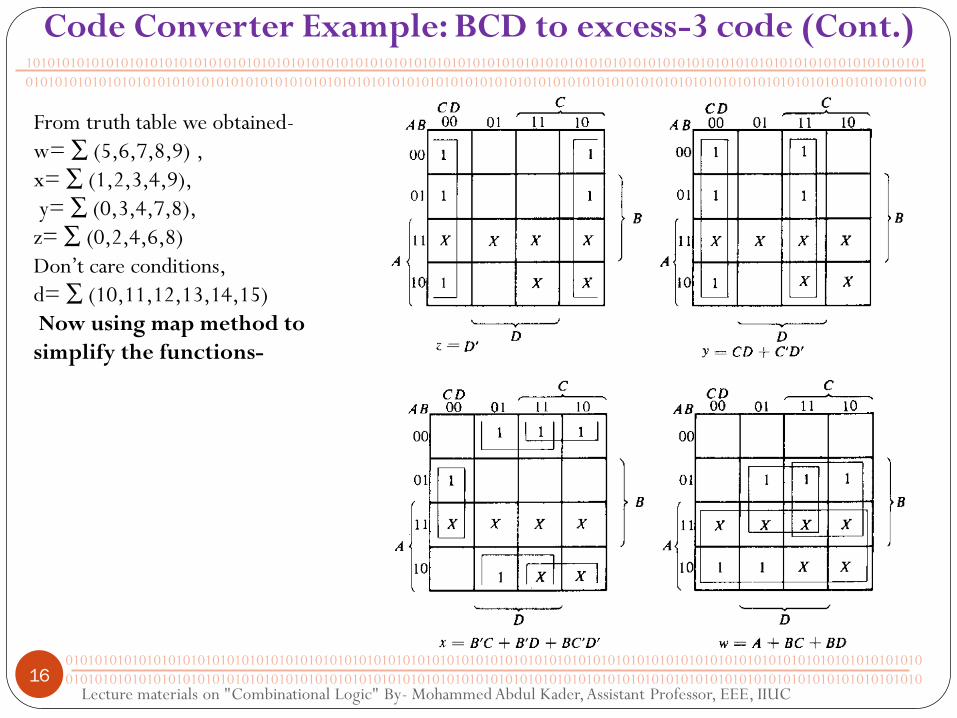
From truth table we obtained-
w= ∑ (5,6,7,8,9) ,
x= ∑ (1,2,3,4,9),
y= ∑ (0,3,4,7,8),
z= ∑ (0,2,4,6,8)
Don’t care conditions,
d= ∑ (10,11,12,13,14,15)
Now using map method to
simplify the functions-

Lecture materials on "Combinational Logic" By- Mohammed Abdul Kader, Assistant Professor, EEE, IIUC 17
101010101010101010101010101010101010101010101010101010101010101010101010101010101010101010101010101010101010101010101010101
010101010101010101010101010101010101010101010101010101010101010101010101010101010101010101010101010101010101010101010101010
010101010101010101010101010101010101010101010101010101010101010101010101010101010101010101010101010101010101010101010
010101010101010101010101010101010101010101010101010101010101010101010101010101010101010101010101010101010101010101010
Code Converter Example: BCD to excess-3 code (Cont.)
Logic Diagram of BCD to excess-3 code converter

Lecture materials on "Combinational Logic" By- Mohammed Abdul Kader, Assistant Professor, EEE, IIUC 18
101010101010101010101010101010101010101010101010101010101010101010101010101010101010101010101010101010101010101010101010101
010101010101010101010101010101010101010101010101010101010101010101010101010101010101010101010101010101010101010101010101010
010101010101010101010101010101010101010101010101010101010101010101010101010101010101010101010101010101010101010101010
010101010101010101010101010101010101010101010101010101010101010101010101010101010101010101010101010101010101010101010
BCD to Seven-segment Decoder
a: Segment designation b: Numerical designation for display
Exercise: 4-14
A BCD to seven-segment decoder is a combinational circuit that accepts a decimal digit in BCD and
generates the appropriate outputs for the selection of segments in a display indicator used for displaying
the decimal digit. The seven output of the decoder (a,b,c,d,e,f,g) select the corresponding segments in
the display as shown in figure a. The numeric designation chosen to represent the decimal digit is shown
in figure b. Design the BCD to seven segment decoder circuit.

Lecture materials on "Combinational Logic" By- Mohammed Abdul Kader, Assistant Professor, EEE, IIUC 19
101010101010101010101010101010101010101010101010101010101010101010101010101010101010101010101010101010101010101010101010101
010101010101010101010101010101010101010101010101010101010101010101010101010101010101010101010101010101010101010101010101010
010101010101010101010101010101010101010101010101010101010101010101010101010101010101010101010101010101010101010101010
010101010101010101010101010101010101010101010101010101010101010101010101010101010101010101010101010101010101010101010
BCD to Seven-segment Decoder
From truth table we obtained-
a= ∑ (0,2,3,5,6,7,8,9)
b= ∑ (0,1,2,3,4,7,8,9)
c= ∑ (0,1,3,4,5,6,7,8,9)
d= ∑ (0,2,3,5,6,8,9)
e= ∑ (0,2,6,8)
f= ∑ (0,4,5,6,8,9)
g= ∑ (2,3,4,5,6,8,9)
Don’t care conditions,
d= ∑ (10,11,12,13,14,15)

Lecture materials on "Combinational Logic" By- Mohammed Abdul Kader, Assistant Professor, EEE, IIUC 20
101010101010101010101010101010101010101010101010101010101010101010101010101010101010101010101010101010101010101010101010101
010101010101010101010101010101010101010101010101010101010101010101010101010101010101010101010101010101010101010101010101010
010101010101010101010101010101010101010101010101010101010101010101010101010101010101010101010101010101010101010101010
010101010101010101010101010101010101010101010101010101010101010101010101010101010101010101010101010101010101010101010
BCD to Seven-segment Decoder
From truth table we obtained-
a= ∑ (0,2,3,5,6,7,8,9) b= ∑ (0,1,2,3,4,7,8,9) c= ∑ (0,1,3,4,5,6,7,8,9) d= ∑ (0,2,3,5,6,8,9)
e= ∑ (0,2,6,8) f= ∑ (0,4,5,6,8,9) g= ∑ (2,3,4,5,6,8,9) Don’t care , d= ∑ (10,11,12,13,14,15)
X X X X
X X
AB
CD
X X X X
X X
AB CD
a= A+C+BD+BD
X X X X
X X
AB CD
b= B +CD+CD c= B +C+D d= A +BD+BC+BCD+CD
X X X X
X X
AB CD
X X X X
X X
AB CD
e= BD+CD
AB CD
X X X X
X X
f= A+CD+BD+BC g= A+BC+BC+BD
AB CD
X X X X
X X

Lecture materials on "Combinational Logic" By- Mohammed Abdul Kader, Assistant Professor, EEE, IIUC 21
101010101010101010101010101010101010101010101010101010101010101010101010101010101010101010101010101010101010101010101010101
010101010101010101010101010101010101010101010101010101010101010101010101010101010101010101010101010101010101010101010101010
010101010101010101010101010101010101010101010101010101010101010101010101010101010101010101010101010101010101010101010
010101010101010101010101010101010101010101010101010101010101010101010101010101010101010101010101010101010101010101010
BCD to Seven-segment Decoder
a= A+C+BD+BD
b= B +CD+CD
c= B +C+D
d= A +BD+BC+BCD+CD
f= A+CD+BD+BC
g= A+BC+BC+BD
e= BD+CD
A B C D
a
b
c
d
e
f
g

Lecture materials on "Combinational Logic" By- Mohammed Abdul Kader, Assistant Professor, EEE, IIUC 22
101010101010101010101010101010101010101010101010101010101010101010101010101010101010101010101010101010101010101010101010101
010101010101010101010101010101010101010101010101010101010101010101010101010101010101010101010101010101010101010101010101010
010101010101010101010101010101010101010101010101010101010101010101010101010101010101010101010101010101010101010101010
010101010101010101010101010101010101010101010101010101010101010101010101010101010101010101010101010101010101010101010
BCD to Seven-segment Decoder
Exercise: 4-12
Design a combinational circuit that detects an error in the representation
of a decimal digit in BCD. The output of the circuit must be equal to
logic-1 when the inputs contain any one of the six unused bit
combinations in the BCD code.
A B C D E
0 0 0 0 0
0 0 0 1 0
0 0 1 0 0
0 0 1 1 0
0 1 0 0 0
0 1 0 1 0
0 1 1 0 0
0 1 1 1 0
1 0 0 0 0
1 0 0 1 0
1 0 1 0 1
1 0 1 1 1
1 1 0 0 1
1 1 0 1 1
1 1 1 0 1
1 1 1 1 1
Tru
th T
able
E= AB+ AC
A
B
C

Lecture materials on "Simplification of Boolean Functions" By- Mohammed abdul kader, Assistant Professor, EEE, IIUC 23
Implementation of basic gates by NAND gate
101010101010101010101010101010101010101010101010101010101010101010101010101010101010101010101010101010101010101010101010101
010101010101010101010101010101010101010101010101010101010101010101010101010101010101010101010101010101010101010101010101010
010101010101010101010101010101010101010101010101010101010101010101010101010101010101010101010101010101010101010101010
010101010101010101010101010101010101010101010101010101010101010101010101010101010101010101010101010101010101010101010
x x
x y
(xy) ((xy)) = xy
x
y
x
y
(xy) = x+y
NOT gate by NAND
gate
AND gate by NAND
gate
OR gate by NAND gate
Multilevel NAND Circuits
The NAND gate is said to be a universal gate because any digital system can be implemented with
it. Combinational circuits and sequential circuits as well can be constructed with this gate because the
flip-flop circuit can constructed from two NAND gates connected back to back.

Lecture materials on "Simplification of Boolean Functions" By- Mohammed abdul kader, Assistant Professor, EEE, IIUC 24
Procedure of Boolean function Implementation-Block Diagram method
101010101010101010101010101010101010101010101010101010101010101010101010101010101010101010101010101010101010101010101010101
010101010101010101010101010101010101010101010101010101010101010101010101010101010101010101010101010101010101010101010101010
010101010101010101010101010101010101010101010101010101010101010101010101010101010101010101010101010101010101010101010
010101010101010101010101010101010101010101010101010101010101010101010101010101010101010101010101010101010101010101010
Multilevel NAND Circuits
1. From the given algebric expression, draw the logic diagram with AND, OR and NOT gates.
Assume that both the normal and complement inputs are available.
2. Draw a second logic diagram with the equivalent NAND logic, substitute for each AND, OR
and NOT gate.
3. Remove any two cascaded inverters from the diagram, since double inversion does not
perform a logic function. Remove inverters connected to a single external inputs and
complement the corresponding input variable. The new logic diagram obtained is the required
NAND gate implementation.
4. The procedure is illustrated in the next slide.

Lecture materials on "Simplification of Boolean Functions" By- Mohammed abdul kader, Assistant Professor, EEE, IIUC 25
Implementation of F=A(B+CD)+BC with NAND gates
101010101010101010101010101010101010101010101010101010101010101010101010101010101010101010101010101010101010101010101010101
010101010101010101010101010101010101010101010101010101010101010101010101010101010101010101010101010101010101010101010101010
010101010101010101010101010101010101010101010101010101010101010101010101010101010101010101010101010101010101010101010
010101010101010101010101010101010101010101010101010101010101010101010101010101010101010101010101010101010101010101010
Multilevel NAND Circuits

Lecture materials on "Simplification of Boolean Functions" By- Mohammed abdul kader, Assistant Professor, EEE, IIUC 26
Implementation of F=(A+B ) (CD+E) with NAND gates
101010101010101010101010101010101010101010101010101010101010101010101010101010101010101010101010101010101010101010101010101
010101010101010101010101010101010101010101010101010101010101010101010101010101010101010101010101010101010101010101010101010
010101010101010101010101010101010101010101010101010101010101010101010101010101010101010101010101010101010101010101010
010101010101010101010101010101010101010101010101010101010101010101010101010101010101010101010101010101010101010101010
Multilevel NAND Circuits

Lecture materials on "Simplification of Boolean Functions" By- Mohammed abdul kader, Assistant Professor, EEE, IIUC 27
Implementation of basic gates by NOR gate
101010101010101010101010101010101010101010101010101010101010101010101010101010101010101010101010101010101010101010101010101
010101010101010101010101010101010101010101010101010101010101010101010101010101010101010101010101010101010101010101010101010
010101010101010101010101010101010101010101010101010101010101010101010101010101010101010101010101010101010101010101010
010101010101010101010101010101010101010101010101010101010101010101010101010101010101010101010101010101010101010101010
x x
x
y
(x+y)
((x+y)) = x+y
x
y
x
y
(x+y) = xy
NOT gate by NOR
gate
OR gate by NOR
gate
AND gate by NOR
gate
Multilevel NOR Circuits
The NOR gate is also called universal gate because all basic gates, combinational circuit as well as
sequential circuit can be constructed with NOR gate

Lecture materials on "Simplification of Boolean Functions" By- Mohammed abdul kader, Assistant Professor, EEE, IIUC 28
Implementation of F=A(B+CD)+BC with NOR gates
101010101010101010101010101010101010101010101010101010101010101010101010101010101010101010101010101010101010101010101010101
010101010101010101010101010101010101010101010101010101010101010101010101010101010101010101010101010101010101010101010101010
010101010101010101010101010101010101010101010101010101010101010101010101010101010101010101010101010101010101010101010
010101010101010101010101010101010101010101010101010101010101010101010101010101010101010101010101010101010101010101010
Multilevel NOR Circuits