com600 series 5.1 master protocols (ethernet) and applications technical reference manual ·...
TRANSCRIPT
—COM600 series 5.1Master Protocols (Ethernet) and ApplicationsTechnical Reference Manual


Contents:
1. About this manual .................................................................................. 9
1.1. Copyright ........................................................................................ 91.2. Disclaimer ..................................................................................... 91.3. Conformity ................................................................................... 101.4. Trademarks .................................................................................. 101.5. General information ..................................................................... 101.6. Document conventions ................................................................ 111.7. Use of symbols ............................................................................ 121.8. Terminology .................................................................................. 121.9. Abbreviations ............................................................................... 141.10. Related documents ...................................................................... 151.11. Document revisions ..................................................................... 15
2. Introduction ........................................................................................... 16
2.1. General information about the COM600 series ........................... 162.2. COM600 product series variants and rationale ........................... 162.3. Functional overview ..................................................................... 172.4. Master protocol OPC server features .......................................... 19
2.4.1. IEC 61850 OPC Server features ................................... 192.4.2. IEC 60870-5-104 OPC Server features ........................ 202.4.3. DNP 3.0 OPC Server features ...................................... 202.4.4. Modbus OPC Server features ....................................... 212.4.5. External OPC Server features ..................................... 222.4.6. SNMP features .............................................................. 222.4.7. SNTP features .............................................................. 23
3. IEC 61850 Master .................................................................................. 24
3.1. About this section ......................................................................... 243.2. IEC 61850 OPC server data object modeling .............................. 24
3.2.1. Common data attribute types ........................................ 243.2.2. IEC 61850 quality .......................................................... 243.2.3. Mapping quality value to OPC ...................................... 253.2.4. Mapping of DetailedQuality ........................................... 263.2.5. Analogue value (AnalogueValue) .................................. 263.2.6. Configuration of analogue value
(ScaledValueConfig) ..................................................... 273.2.7. Range configuration (RangeConfig) ............................. 273.2.8. Step position with transient indication
(ValWithTrans) .............................................................. 283.2.9. Pulse configuration (PulseConfig) ................................. 283.2.10. Originator ...................................................................... 283.2.11. Unit ................................................................................ 293.2.12. Vector ............................................................................ 293.2.13. TimeStamp .................................................................... 29
3
COM600 series 5.11MRS758690
Master Protocols (Ethernet) and Applications TechnicalReference Manual
Issued: 12.4.2018Version: B/12.04.2018
3.2.14. AbbCommandBitmask .................................................. 303.2.15. Common data class specifications for status
information .................................................................... 313.2.15.1. Single point status (SPS) ........................... 313.2.15.2. Double point status (DPS) .......................... 313.2.15.3. Integer status (INS) .................................... 323.2.15.4. Enumerated Status (ENS) .......................... 333.2.15.5. Protection activation information (ACT) ...... 333.2.15.6. Directional protection activation information
(ACD) .......................................................... 343.2.15.7. Security violation counter (SEC) ................ 353.2.15.8. Binary counter reading (BCR) .................... 36
3.2.16. Common data class specifications for measuredinformation .................................................................... 373.2.16.1. Measured value (MV) ................................. 373.2.16.2. Complex measured value (CMV) ............... 383.2.16.3. Sampled value (SAV) ................................. 393.2.16.4. WYE ........................................................... 403.2.16.5. Delta (DEL) ................................................. 403.2.16.6. Sequence (SEQ) ........................................ 41
3.2.17. Common data class specifications for controllable statusinformation .................................................................... 423.2.17.1. Controllable single point (SPC) .................. 423.2.17.2. Controllable double point (DPC) ................. 443.2.17.3. Controllable integer status (INC) ................ 473.2.17.4. Controllable Enumerated Status (ENC) ..... 483.2.17.5. Binary controlled step position information
(BSC) .......................................................... 503.2.17.6. Integer controlled step position information
(ISC) ........................................................... 523.2.18. Common data class specifications for controllable
analogue information .................................................... 543.2.18.1. Analog set point (APC) ............................... 54
3.2.19. Common data class specifications for statussettings .......................................................................... 563.2.19.1. Single point setting (SPG) .......................... 563.2.19.2. Integer status setting (ING) ........................ 56
3.2.20. Common data class specifications for analoguesettings .......................................................................... 573.2.20.1. Analogue setting (ASG) .............................. 573.2.20.2. Setting curve (CURVE) ............................... 58
3.2.21. Common data class specifications for descriptioninformation .................................................................... 593.2.21.1. Device name plate (DPL) ........................... 593.2.21.2. Logical node name plate (LPL) .................. 59
3.2.22. Application error codes ................................................. 603.3. Attributes ...................................................................................... 61
3.3.1. General information about attributes ............................. 61
4
1MRS758690COM600 series 5.1
Master Protocols (Ethernet) and Applications TechnicalReference Manual

3.3.2. Server attributes ............................................................ 613.3.3. IEC 61850 subnetwork attributes .................................. 633.3.4. IEC 61850 device attributes .......................................... 663.3.5. Transparent XSAT ......................................................... 703.3.6. IEC 61850 logical device attributes ............................... 73
3.4. IEC 61850 File transfer ................................................................ 733.4.1. General information about IEC 61850 File Transfer ..... 733.4.2. File Transfer attributes .................................................. 743.4.3. File Transfer services .................................................... 753.4.4. File Transfer service codes ........................................... 80
3.5. ACSI conformance statement ...................................................... 813.5.1. General information about ACSI conformance
statement ...................................................................... 813.5.2. ACSI basic conformance statement .............................. 823.5.3. ACSI models conformance statement .......................... 823.5.4. ACSI service conformance statement ........................... 84
4. IEC 104 OPC server .............................................................................. 89
4.1. About this section ....................................................................... 1154.2. IEC 61850 data modeling ............................................................ 89
4.2.1. General information about IEC 61850 data modeling .... 894.2.2. Single point status (SPS) .............................................. 894.2.3. Double point status (DPS) ............................................ 904.2.4. Integer status (INS) ....................................................... 904.2.5. Enumerated Status (ENS) ............................................ 904.2.6. Protection activation information (ACT) ........................ 914.2.7. Directional protection activation information (ACD) ...... 914.2.8. Binary counter reading (BCR) ....................................... 924.2.9. Measured value (MV) .................................................... 924.2.10. Complex measured value (CMV) .................................. 934.2.11. WYE .............................................................................. 934.2.12. Delta (DEL) ................................................................... 944.2.13. Controllable single point (SPC) ..................................... 944.2.14. Controllable double point (DPC) ................................... 944.2.15. Controllable integer status (INC) ................................... 954.2.16. Controllable Enumerated Status (ENC) ........................ 954.2.17. Binary controlled step position information (BSC) ........ 964.2.18. Integer controlled step position information (ISC) ......... 964.2.19. Analogue set point (APC) ............................................. 96
4.3. Status codes ................................................................................ 974.3.1. Introduction ................................................................... 974.3.2. Link layer status codes ................................................. 974.3.3. Application layer status codes ...................................... 97
4.4. Attributes ...................................................................................... 984.4.1. Server attributes ............................................................ 984.4.2. Channel attributes ......................................................... 994.4.3. Device attributes ......................................................... 100
5
COM600 series 5.11MRS758690
Master Protocols (Ethernet) and Applications TechnicalReference Manual

5. DNP3 LAN/WAN OPC server .............................................................. 102
5.1. About this section ....................................................................... 1155.2. IEC 61850 data modeling .......................................................... 102
5.2.1. General information about IEC 61850 data modeling .. 1025.2.2. Single point status (SPS) ............................................ 1025.2.3. Double point status (DPS) .......................................... 1035.2.4. Integer status (INS) ..................................................... 1035.2.5. Enumerated Status (ENS) .......................................... 1035.2.6. Protection activation information (ACT) ...................... 1045.2.7. Directional protection activation information (ACD) .... 1045.2.8. Binary counter reading (BCR) ..................................... 1055.2.9. Device name plate (DPL) ............................................ 1055.2.10. Logical node name plate (LPL) ................................... 1055.2.11. Measured value (MV) .................................................. 1065.2.12. Complex measured value (CMV) ................................ 1065.2.13. WYE ............................................................................ 1075.2.14. Delta (DEL) ................................................................. 1105.2.15. Controllable single point (SPC) ................................... 1115.2.16. Controllable double point (DPC) ................................. 1125.2.17. Controllable integer status (INC) ................................. 1125.2.18. Controllable Enumerated Status (ENC) ...................... 1125.2.19. Binary controlled step position information (BSC) ...... 1135.2.20. Integer controlled step position information (ISC) ....... 1135.2.21. Analogue set point (APC) ........................................... 113
6. MODBUS TCP server .......................................................................... 115
6.1. About this section ....................................................................... 1156.2. IEC 61850 data modeling .......................................................... 115
6.2.1. General information about IEC 61850 data modeling .. 1156.2.2. Data objects for status information ............................. 115
6.2.2.1. Single point status (SPS) ......................... 1156.2.2.2. Double point status (DPS) ........................ 1166.2.2.3. Integer status (INS) .................................. 1166.2.2.4. Enumerated Status (ENS) ........................ 1166.2.2.5. Protection activation information (ACT) .... 1176.2.2.6. Binary counter reading (BCR) .................. 1176.2.2.7. Device name plate (DPL) ......................... 1186.2.2.8. Logical node name plate (LPL) ................ 118
6.2.3. Data objects for measured information ....................... 1186.2.3.1. Measured value (MV) ............................... 1186.2.3.2. WYE ......................................................... 1196.2.3.3. Delta (DEL) ............................................... 121
6.2.4. Data objects for controllable status information .......... 1236.2.4.1. Controllable single point (SPC) ................ 1236.2.4.2. Controllable double point (DPC) ............... 1236.2.4.3. Controllable integer status (INC) .............. 124
6
1MRS758690COM600 series 5.1
Master Protocols (Ethernet) and Applications TechnicalReference Manual

6.2.4.4. Controllable Enumerated Status (ENC) .... 1246.2.4.5. Binary controlled step position information
(BSC) ........................................................ 1256.2.4.6. Integer controlled step position information
(ISC) ......................................................... 1256.2.5. Data objects for controllable analogue information ..... 125
6.2.5.1. Analogue set point (APC) ......................... 1256.3. Attributes .................................................................................... 126
6.3.1. Server attributes .......................................................... 1266.3.2. Modbus channel attributes .......................................... 1276.3.3. Modbus Device attributes ........................................... 128
6.4. Status codes .............................................................................. 1296.4.1. Status codes ............................................................... 129
7. Redundant OPC server ...................................................................... 131
7.1. Introduction ................................................................................ 1317.2. Redundant OPC Server Properties ........................................... 1317.3. Redundant Subnet Properties ................................................... 1317.4. Redundant IED Properties ......................................................... 1327.5. Redundant Data Object Properties ............................................ 134
8. Appendix 1 ......................................................................................... 136
8.1. Interoperability list for IEC104 OPC Server ............................... 136
9. Appendix 2 ......................................................................................... 152
9.1. Device profile ............................................................................. 152
Index ............................................................................................................ 161
7
COM600 series 5.11MRS758690
Master Protocols (Ethernet) and Applications TechnicalReference Manual

8

About this manual1.
Copyright1.1.
This document and parts thereof must not be reproduced or copied without written per-mission from ABB, and the contents thereof must not be imparted to a third party, norused for any unauthorized purpose.
The software or hardware described in this document is furnished under a license andmay be used, copied, or disclosed only in accordance with the terms of such license.
Warranty
Please inquire about the terms of warranty from your nearest ABB representative.
http://www.abb.com/substationautomation
Disclaimer1.2.
The data, examples and diagrams in this manual are included solely for the concept orproduct description and are not to be deemed as a statement of guaranteed properties.All persons responsible for applying the equipment addressed in this manual must satisfythemselves that each intended application is suitable and acceptable, including that anyapplicable safety or other operational requirements are complied with. In particular, anyrisks in applications where a system failure and/ or product failure would create a riskfor harm to property or persons (including but not limited to personal injuries or death)shall be the sole responsibility of the person or entity applying the equipment, and thoseso responsible are hereby requested to ensure that all measures are taken to exclude ormitigate such risks.
This product is designed to be connected and to communicate information and data viaa network interface, which should be connected to a secure network. It is sole responsib-ility of person or entity responsible for network administration to ensure a secure connec-tion to the network and to establish and maintain any appropriate measures (such as butnot limited to the installation of firewalls, application of authentication measures,encryption of data, installation of anti virus programs, etc) to protect the product, thenetwork, its system and the interface against any kind of security breaches, unauthorizedaccess, interference, intrusion, leakage and/or theft of data or information. ABB is notliable for damages and/or losses related to such security breaches, unauthorized access,interference, intrusion, leakage and/or theft of data or information.
This document has been carefully checked by ABB but deviations cannot be completelyruled out. In case any errors are detected, the reader is kindly requested to notify themanufacturer. Other than under explicit contractual commitments, in no event shall ABB
9
COM600 series 5.11MRS758690
Master Protocols (Ethernet) and Applications Technical Refer-ence Manual

be responsible or liable for any loss or damage resulting from the use of this manual orthe application of the equipment.
Conformity1.3.
This product complies with the directive of the Council of the European Communitieson the approximation of the laws of the Member States relating to electromagneticcompatibility (EMC Directive 2004/108/EC) and concerning electrical equipment foruse within specified voltage limits (Low-voltage directive 2006/95/EC). This conformityis the result of tests conducted by ABB in accordance with the product standards EN50263 and EN 60255-26 for the EMC directive, and with the product standards EN60255-1 and EN 60255-27 for the low voltage directive. The product is designed inaccordance with the international standards of the IEC 60255 series.
Trademarks1.4.
ABB is a registered trademark of ABB Group. All other brand or product names men-tioned in this document may be trademarks or registered trademarks of their respectiveholders.
General information1.5.
This manual provides thorough information on all the Ethernet-based Master protocolssupported by the COM600 and and their central concepts. You find instructions on howto configure the related objects belonging to the different Ethernet-based master protocolservers. The basic operation procedures are also discussed.
Information in this user’s manual is intended for application engineers.
As a prerequisite, you should understand the basic principles of the different Ethernet-based master protocols and the IEC 61850 standard.
This user’s manual is divided into following sections:
Introduction
This section gives an overview of the Ethernet based master protocol servers andtheir features.
10
1MRS758690COM600 series 5.1
Master Protocols (Ethernet) and Applications Technical Refer-ence Manual

Configuration
In this section you will find an overview of configuration. You are given instructionson how to configure Master Protocol OPC Server related objects and the model of asubstation or system.
Operation
This section covers the basic operation procedures you can carry out when transferringor activating COM600 with new configurations.
You are also given instructions on how to monitor and control the conditions of substationcommunication network.
Technical reference
This section contains a list of status codes and information about the IEC 61850 datamodeling.
Document conventions1.6.
The following conventions are used for the presentation of material:• The words in names of screen elements (for example, the title in the title bar of a
window, the label for a field of a dialog box) are initially capitalized.• Capital letters are used for the name of a keyboard key if it is labeled on the keyboard.
For example, press the ENTER key.• Lowercase letters are used for the name of a keyboard key that is not labeled on the
keyboard. For example, the space bar, comma key, and so on.• Press CTRL+C indicates that you must hold down the CTRL key while pressing
the C key (to copy a selected object in this case).• Press ESC E C indicates that you press and release each key in sequence (to copy
a selected object in this case).• The names of push and toggle buttons are boldfaced. For example, click OK.• The names of menus and menu items are boldfaced. For example, the File menu.
• The following convention is used for menu operations: MenuName > Menu-Item > CascadedMenuItem. For example: select File > New > Type.
• The Start menu name always refers to the Start menu on the Windows taskbar.• System prompts/messages and user responses/input are shown in the Courier font.
For example, if you enter a value out of range, the following message is displayed:
Entered value is not valid. The value must be 0 - 30 .
• You can be asked to enter the string MIF349 in a field. The string is shown as followsin the procedure:
11
COM600 series 5.11MRS758690
Master Protocols (Ethernet) and Applications Technical Refer-ence Manual

MIF349• Variables are shown using lowercase letters:
sequence name
Use of symbols1.7.
This publication includes warning, caution, and information icons that point out safety-related conditions or other important information. It also includes tip icons to point outuseful information to the reader. The corresponding icons should be interpreted as follows.
The electrical warning icon indicates the presence of a hazardwhich could result in electrical shock.
The warning icon indicates the presence of a hazard whichcould result in personal injury.
The caution icon indicates important information or warningrelated to the concept discussed in the text. It may indicatethe presence of a hazard which could result in corruption ofsoftware or damage to equipment or property.
The information icon alerts the reader to relevant facts andconditions.
The tip icon indicates advice on, for example, how to designyour project or how to use a certain function.
Terminology1.8.
DescriptionTerm
An abnormal state of a condition.Alarm
An OPC service for providing information about alarms andevents to OPC clients.
Alarms and Events; AE
COM600 as a generic name for COM600S IEC and COM600FANSI products
COM600 Series; COM600
12
1MRS758690COM600 series 5.1
Master Protocols (Ethernet) and Applications Technical Refer-ence Manual

DescriptionTerm
An OPC service for providing information about process data toOPC clients.
Data Access; DA
Part of a logical node object representing specific information,for example, status, or measurement. From an object-orientedpoint of view, a data object is an instance of a class data object.DOs are normally used as transaction objects; that is, they aredata structures.
Data Object; DO
The data set is the content basis for reporting and logging. Thedata set contains references to the data and data attribute val-ues.
Data Set
A physical device that behaves as its own communication nodein the network, for example, protection relay.
Device
Change of process data or an OPC internal value. Normally, anevent consists of value, quality, and timestamp.
Event
A physical IEC 61850 device that behaves as its own commu-nication node in the IEC 61850 protocol.
Intelligent Electronic Device
Representation of a group of functions. Each function is definedas a logical node. A physical device consists of one or severalLDs.
Logical Device; LD
The smallest part of a function that exchanges data. An LN isan object defined by its data and methods.
Logical Node; LN
Series of standards specifications aiming at open connectivityin industrial automation and the enterprise systems that supportindustry.
OPC
Representation of a connection to the data source within theOPC server. An OPC item is identified by a string <objectpath>:<property name>. Associated with each OPC item areValue, Quality, and Time Stamp.
OPC item
Named data item.Property
The report control block controls the reporting processes forevent data as they occur. The reporting process continues aslong as the communication is available.
Report Control Block
ABB proprietary communication protocol used in substationautomation.
SPA
Protection and/or Control Product supporting the SPA protocolversion 2.5 or earlier.
SPA device
XML-based description language for configurations of electricalsubstation IEDs. Defined in IEC 61850 standard.
Substation Configuration Lan-guage; SCL
13
COM600 series 5.11MRS758690
Master Protocols (Ethernet) and Applications Technical Refer-ence Manual

Abbreviations1.9.
The following is a list of abbreviations associated with COM600 that you should befamiliar with. See also 1.8, Terminology.
DescriptionAbbreviation
Alarms and EventsAE
Application Service Data UnitASDU
Buffered Report Control BlockBRCB
Data AccessDA
Data Message Code DefinitionDMCD
Data ObjectDO
Gateway, component connecting two communication networks togetherGW
Web Human Machine InterfaceWebHMI
International Electrotechnical CommissionIEC
Intelligent Electronic DeviceIED
Local Area NetworkLAN
Logical DeviceLD
Logical NodeLN
Network Control CenterNCC
Norwegian User ConventionNUC
Object Linking and EmbeddingOLE
OLE for Process ControlOPC
Protection & ControlP&C
Programmable Logic ControllerPLC
Program Organization UnitPOU
Request To SendRTS
Substation AutomationSA
Substation Configuration DescriptionSCD
Substation Configuration LanguageSCL
Sequential Function ChartSFC
Single Line DiagramSLD
Simple Network Management ProtocolSNMP
Simple Network Time ProtocolSNTP
Report Control BlockRCB
Unbuffered Report Control BlockURCB
eXtended Markup LanguageXML
14
1MRS758690COM600 series 5.1
Master Protocols (Ethernet) and Applications Technical Refer-ence Manual
Related documents1.10.
MRS numberName of the manual
1MRS756125COM600 User’s Manual
Document revisions1.11.
HistoryProduct revisionDocument version/date
Document created5.0A/24.5.2017
Document revised5.1B/12.4.2018
15
COM600 series 5.11MRS758690
Master Protocols (Ethernet) and Applications Technical Refer-ence Manual

Introduction2.
General information about the COM600 series2.1.
The COM600 product series are versatile Substation Management Units that help realizesmart substation and grid automation solutions in industrial and utility distribution net-works.
They get deployed together with protection and control IEDs, substation devices suchas RTUs, meters and PLCs in dedicated cabinets and switchgear.
The COM600 product is an all-in-one unit that functions as:• Communication gateway• Web Human Machine Interface (WebHMI)• Automation controller• Real-time and historical data management unit
The COM600 product series use process information and device data, acquired overEthernet or serial communication protocol interfaces to execute specific substationfunctions and applications. Thus, they are critical building blocks to realize substationsecondary system solutions and in the process solving diverse customer needs.
COM600 product series variants and rationale2.2.
To facilitate substation and grid automation solutions in IEC and ANSI market areas, avariant-based system similar to Relion® 615 and 620 series is being followed fromCOM600 5.0 release.
The main reasons for such an approach are the following:
• To ensure all COM600 product series features are advantageously used in end-cus-tomer projects in the medium voltage substation automation domain.
• To ensure an optimum feature set to be bundled together to realize specific applica-tions required in IEC and ANSI market areas.
• To ensure a future-proof product approach.
This release then comprises of two variants, based on the primary intent or applicationare defined as follows:• COM600S IEC – COM600 for substation automation, analysis and data management
(for IEC markets)• COM600S IEC is a substation automation, analyzer and data management unit
that integrates devices, facilitates operations, manages communication and runsanalysis applications pertinent to equipment or operations in utility or industrialdistribution substations.
• COM600F ANSI – COM600 as distribution automation controller (for ANSI markets)
16
1MRS758690COM600 series 5.1
Master Protocols (Ethernet) and Applications Technical Refer-ence Manual

• COM600F is a dedicated distribution automation controller unit that runs dis-tributed grid and feeder applications for ANSI power networks and inherits allcore features of the COM600 series.
Functional overview2.3.
The COM600 supports multiple master communication protocols by which it exchangesdata with field devices such as protection and control IEDs, meters or other devices suchstation controllers, Ethernet switches and WebHMIs. The data communication can beaccomplished using Ethernet or serial interfaces such as RS 232 or RS 485. The followingmaster protocols are supported by the COM600:
1. Ethernet-based protocols• IEC 61850-8-1• IEC 60870-5-104• DNP 3.0 LAN/WAN• Modbus• OPC• SNMP
2. Serial interface-based protocols• IEC 60870-5-101• IEC 60870-5-103• DNP 3.0 Serial• Modbus• SPA
The COM600 converts all field data, acquired using above communication protocols,into OPC. An OPC server is dedicated to every supported protocol. This OPC serverenables other OPC clients (internal) to access process data from slave devices.
This manual specifically covers the above listed Ethernet based master protocols.
17
COM600 series 5.11MRS758690
Master Protocols (Ethernet) and Applications Technical Refer-ence Manual

SysConf.bmp
Figure 2.3-1 System overview
1. Network Control Center (NCC), Distributed Control System (DCS)2. Station Automation Builder 600 (SAB600)3. COM600 with Ethernet-based OPC Server (IEC 61850/IEC 60878-5-104/DNP3.0-
LAN/MODBUS-TCP/OPC/SNMP/SNTP)4. Ethernet switch (SNMP compliant)5. Field devices like protection and control devices, meters etc. using respective master
protocols.
The protocol handling, that is, configuration and operation aspects comprise of genericand specific aspects. These generic and specific parts will be described separately in thismanual.
Handling in brief:
All master (client) protocols have two common aspects
• An OPC server layer• Data modeling based on IEC 61850
While the OPC server layer provides access to data from the slave devices, the IEC61850 data model creates a common and protocol-independent data interface betweenthe OPC server and the Master protocol (client) layer. All the 3 layers together are referredas a ‘Master protocol OPC server’. Each master protocol OPC server is a separate identity.
18
1MRS758690COM600 series 5.1
Master Protocols (Ethernet) and Applications Technical Refer-ence Manual

handling_in_brief.png
Figure 2.3-2
The master protocol and OPC server layers are runtime software components. The IEC61850 data model is built based on the imported SCL file using Station AutomationBuilder 600 (SAB600). To simplify the protocol conversion and the signal mapping,each master protocol OPC server uses the same common data modeling (common dataclasses and services) specified in the IEC 61850 standard. The COM600 configurationdata is also in SCL (XML-based) format.
After the master protocol OPC server is launched, it reads the configuration data andestablishes communication with the slave devices through the master (client) protocolstack. Configured slave devices and their data are then exposed to OPC clients (WebServer, slave protocols etc.) through the master protocol OPC server. The slave devices’reported data changes together with Data Access subscription are reported to the sub-scribing OPC clients.
The Master protocol OPC server component handles the data transfer and conversionbetween the underlying master protocol communication stack and OPC interfaces.
Master protocol OPC server features2.4.
IEC 61850 OPC Server features2.4.1.
The IEC 61850 standard is a set of specifications, which detail a layered approach tosubstation communication architecture. It specifies the usage of Manufacturing MessageSpecification (MMS, ISO 9506) between the IEC 61850 server (slave devices) and IEC61850 client (IEC 61850 OPC Server, master). The COM600 IEC 61850 OPC servercan subscribe to both MMS and GOOSE based data. However, it can only send MMSbased command information to the slave devices.
The IEC 61850 OPC Server supports the following features:
19
COM600 series 5.11MRS758690
Master Protocols (Ethernet) and Applications Technical Refer-ence Manual

• OPC Data Access v. 1.0/2.0• OPC Alarms and Events specifications v. 1.10• Communication diagnostics• IEC 61850 data modeling• System supervision:
• IEC 61850 device communication• Command handling:
• The IEC 61850 OPC Server supports the IEC 61850 command services.• • SPS, DPS, INS, ACT, ACD, SEC, BCR, MV, CMV, SAV, WYE, DEL, SEQ,
SPC, DPC, BSC, ISC, APC, SPG, ING, ASG, CURVE, DPL, LPL.• IEC 61850 buffered and unbuffered reporting services• IEC 61850 File Transfer• IEC 61850 GOOSE receive (received GOOSE data updated to OPC)• Automatic Disturbance Recording upload using IEC 61850 file transfer or FTP• SPA TCP• SPA Parameter access (configured with Parameter Filtering Tool)• Time synchronization:
• The IEC 61850 OPC Server can act as an SNTP client and server for time syn-chronization. When the IEC 61850 OPC Server is configured for receiving timesynchronization, it updates the operating system time of the PC.
• Multiple instance support• GOOSE Analyzer support
IEC 60870-5-104 OPC Server features2.4.2.
The IEC 60870-5-104 (IEC 104) protocol is a standard for power system monitoring,control and associated communications for telecontrol, protection and associated tele-communications for electric power systems. The IEC 104 master protocol implementationin the COM600 uses a TCP/IP interface for substation LAN (Local Area Network)connectivity and thereby to field slave devices supporting IEC 104. The application layerof IEC 104 is preserved same as that of IEC 101.
The IEC 104 OPC Server supports the following features:• OPC Data Access v. 1.0/2.0• OPC Alarms and Events specification v. 1.10• IEC 61850 data modeling• System supervision:
• IEC 104 channel supervision• IEC 104 device communication
• Supported IEC 60870-5-104 data types and functions.
DNP 3.0 OPC Server features2.4.3.
DNP3 (Distributed Network Protocol) is a de-facto communication protocol for commu-nication between SCADA master stations (control centres), RTUs, protection and control
20
1MRS758690COM600 series 5.1
Master Protocols (Ethernet) and Applications Technical Refer-ence Manual

devices and meters. It is used mainly in electric and water utilities. The COM600 incor-porates the DNP 3.0 master LAN/WAN for Ethernet based communication with stationdevices.
The DNP LAN/WAN OPC Server supports the following features:• OPC Data Access v. 1.0/2.0• OPC Alarms and Events specifications v. 1.10• IEC 61850 data modeling• System supervision:
• DNP channel communication• DNP device communication
• Level of DNP implementation
Modbus OPC Server features2.4.4.
Modbus is a de-facto standard communication protocol used in electrical and industrialprocess data exchange between substation devices such as IEDs, meters or PLCs withCOM600.
The Modbus OPC Server is intended for connecting simple Modbus devices like energymeters and input/ouput modules. As the protocol is based on scanning the state of theinputs of the device, it depends on the scan rate how short signal transients are registered.No events or time stamps are supported.
The Modbus messaging service provides a client/server communication between devicesconnected on an Ethernet TCP/IP network. This model is based on four types of messages:request, confirmation, indication, and response.
A system using Modbus TCP/IP can include different types of devices. There can beModbusTCP/IP client and server devices connected to an TCP/IP network. There canalso be devices such as bridges, routers and gateways for connections between the TCP/IPnetwork and a serial line sub-network, permitting connections to Modbus serial line clientand server end devices.
The Modbus OPC Server supports the following features:
• OPC Data Access v. 1.0/2.0• OPC Alarms and Events specifications v. 1.10• IEC 61850 data modeling• System supervision:
• Modbus channel communication• Modbus device communication
Supported transmission modes:• Modbus RTU• Modbus ASCII
21
COM600 series 5.11MRS758690
Master Protocols (Ethernet) and Applications Technical Refer-ence Manual

Table 2.4.4-1 The function codes supported by Modbus OPC ServerMemory areaDescriptionFunction code
00001 - 09999Read coil status01
10001 - 19999Read input status02
40001 - 49999Read holding register03
30001 - 39999Read input registers04
00001 - 09999Force single coil05
40001 - 49999Write single register06
40001 - 49999Write multiple registers16
60001 - 65535Write General Reference21
The following data formats are supported:• Bit, one coil, or input status• Word, one register in IED's memory. The data is used in an unsigned form• Integer, one register in IED's memory. The MSB bit is used as a sign bit• Long MSW last, signed 32-bit object, which needs two registers from IED's memory
in lsw-msw order• Long MSW first, signed 32-bit object which needs two registers from IED's memory
in msw-lsw order.• Float MSW last, floating point type which needs two input registers from IED's
memory in lsw-msw order• Float MSW first, floating point type which needs two input registers from IED's
memory in msw-lsw order.
External OPC Server features2.4.5.
OPC Data Access is used for continuous, real-time data communication betweenPLC/DCS systems and COM600 communicating real-time data from data acquisitiondevices such as PLCs to display and interface devices like Web Human-Machine Inter-faces (WebHMI). OPC DA is also used for inter-process communication in COM600.
SNMP features2.4.6.
The Simple Network Management Protocol (SNMP) is used to manage network con-nectivity of substation devices in the substation LAN network.
The SNMP OPC Server is intended for providing methods for OPC clients to monitornetwork-attached devices.
The SNMP OPC Server supports the following features:• SNMP V1, SNMPv2c and SNMPV3 network monitoring
22
1MRS758690COM600 series 5.1
Master Protocols (Ethernet) and Applications Technical Refer-ence Manual

• IEC 61850 data modeling• System supervision
• SNMP channel communication• SNMP device communication
SNTP features2.4.7.
The Simple Network Time Protocol (SNTP) is used for clock synchronization betweensubstation devices. Specifically, COM600 can act as an SNTP master to synchronize theinternal clocks of the protection and control IEDs (SNTP slaves), in the absence of adedicated GPS (SNTP server).
The SNTP OPC Server supports the following features:• OPC Data Access Server v. 1.0/2.0• OPC Alarms and Events server v. 1.10• SNTP client and server for time synchronization
23
COM600 series 5.11MRS758690
Master Protocols (Ethernet) and Applications Technical Refer-ence Manual
IEC 61850 Master3.
About this section3.1.
This document describes how IEC 61850 data objects according to IEC 61850-7-3 aremapped to OPC nodes and item tags.
In general it is done by using an OPC node to represent an IEC 61850 object, and OPCitem tags to represent the attributes of the object. Most objects are single-level (that is,use only on node) but some are hierarchical and use several nodes.
This section provides reference information about the following issues:• IEC 61850 data object modeling• IEC 61850 OPC Server data object modeling• Attributes• Status codes
IEC 61850 OPC server data object modeling3.2.
Common data attribute types3.2.1.
The following sections describe how the IEC 61850 data object attributes and servicesare presented on the OPC server name space.
The columns in the tables have the following content types:• Name specifies the OPC item name of the attribute or service.• Type specifies the IEC 61850 type of the attribute.• Value/Value range specifies the allowed values and ranges of the attribute or service.• Mandatory/Optional specifies whether the attribute is considered as mandatory or
optional according to the IEC 61850 standard.• OPC data type specifies the OPC data type used for the OPC item.• Bit specifies how many bits the attribute takes.• Description describes the data type and access and gives useful information.
IEC 61850 quality3.2.2.
The following table defines the mapping of quality in MMS (IEC 61850 7-3). Only 14bits (LSB) in quality are valid.
24
1MRS758690COM600 series 5.1
Master Protocols (Ethernet) and Applications Technical Refer-ence Manual

Table 3.2.2-1 IEC 61850 qualityBitM/O/CValue/Value
rangeTypeName
0-1Mgood (0) | invalid(1) | reserved (2)| questionable (3)
2bitvalidity
2MFALSE (0) |TRUE (1)
1bitoverflow
3MFALSE (0) |TRUE (1)
1bitoutOfRange
4MFALSE (0) |TRUE (1)
1bitbadReference
5MFALSE (0) |TRUE (1)
1bitoscillatory
6MFALSE (0) |TRUE (1)
1bitfailure
7MFALSE (0) |TRUE (1)
1bitoldData
8MFALSE (0) |TRUE (1)
1bitinconsistent
9MFALSE (0) |TRUE (1)
1bitinaccurate
10-11Mprocess (0) | sub-stituted (1)
2bitsource
12MFALSE (0) |TRUE (1)
1bittest
13MFALSE (0) |TRUE (1)
1bitoperatorBlocked
Mapping quality value to OPC3.2.3.
The value of validity is presented as the value of the quality attribute. The other valuesare presented as OPC properties of the quality in the OPC namespace.
Table 3.2.3-1 Mapping quality value to OPCOPC Data TypeM/O/CValue/ Value
rangeTypeName
VT_I4Mgood (0) | invalid(1) | reserved (2)| questionable (3)
Validity
VT_I4MDetailedQualityDetailQuality
VT_I4Mprocess (0) | sub-stituted (1)
Source
25
COM600 series 5.11MRS758690
Master Protocols (Ethernet) and Applications Technical Refer-ence Manual

OPC Data TypeM/O/CValue/ Valuerange
TypeName
VT_BOOLMFALSE (0) |TRUE (1)
Test
VT_BOOLMFALSE (0) |TRUE (1)
OperatorBlocked
Mapping of DetailedQuality3.2.4.
The value of DetailQuality is mapped to a DetailedQuality bitmap.
Table 3.2.4-1 Mapping of DetailedQualityBitM/O/CValue/ Value
rangeTypeName
0MFALSE (0) |TRUE (1)
1bitoverflow
1MFALSE (0) |TRUE (1)
1bitoutOfRange
2MFALSE (0) |TRUE (1)
1bitbadReference
3MFALSE (0) |TRUE (1)
1bitoscillatory
4MFALSE (0) |TRUE (1)
1bitfailure
5MFALSE (0) |TRUE (1)
1bitoldData
6MFALSE (0) |TRUE (1)
1bitinconsistent
7MFALSE (0) |TRUE (1)
1bitinaccurate
Example:
DetailQuality = 1d = 00000001b > overflow = true
DetailQuality = 16d = 00010000b > failure = true
Analogue value (AnalogueValue)3.2.5.
Analogue values are always presented as 32-bit float values (VT_R4) so that the .f and.i extensions are discarded from the attribute names to simplify the OPC namespace. Ifa device only supports integer values, the value is converted to a floating point present-ation of the value according to its configuration and the following formula, refer to3.2.6, Configuration of analogue value (ScaledValueConfig).
26
1MRS758690COM600 series 5.1
Master Protocols (Ethernet) and Applications Technical Refer-ence Manual

ƒ×10units.multiplier = (¡×scaleFactor)+offset
Table 3.2.5-1 Analogue value (AnalogueValue)OPC Data TypeM/O/CValue/ Value
rangeTypeName
Not UsedNot Usedinteger valueINT32i
Not UsedNot Usedfloating pointvalue
FLOAT32f
Example:
MV: mag.f (VT_R4) & mag.i (VT_I4) > mag (VT_R4)
Configuration of analogue value (ScaledValueConfig)3.2.6.
The following table defines the mapping of configuration of analogue value (ScaledValue-Config).
Table 3.2.6-1 Configuration of analogue value (ScaledValueConfig)OPC Data TypeM/O/CValue/ Value
rangeTypeName
VT_R4Mfloating pointvalue
FLOAT32scaleFactor
VT_R4Mfloating pointvalue
FLOAT32offset
Range configuration (RangeConfig)3.2.7.
The following table defines the mapping of range configuration (RangeConfig).
Table 3.2.7-1 Range configuration (RangeConfig)OPC Data TypeM/O/CValue/ Value
rangeTypeName
VT_R4Mfloating pointvalue
AnalogueValuehhLim
VT_R4Mfloating pointvalue
AnalogueValuehLim
VT_R4Mfloating pointvalue
AnalogueValuelLim
VT_R4Mfloating pointvalue
AnalogueValuellLim
VT_R4Mfloating pointvalue
AnalogueValuemin
27
COM600 series 5.11MRS758690
Master Protocols (Ethernet) and Applications Technical Refer-ence Manual
OPC Data TypeM/O/CValue/ Valuerange
TypeName
VT_R4Mfloating pointvalue
AnalogueValuemax
hhLim, hLim, lLim, llLim: These attributes are configuration parameters used in thecontext with the range attribute.
min: The min (minimum) attribute represents the minimum process measurement forwhich values of i or f are considered within process limits.
max: The max (maximum) attribute represents the maximum process measurement forwhich values of i or f are considered within process limits.
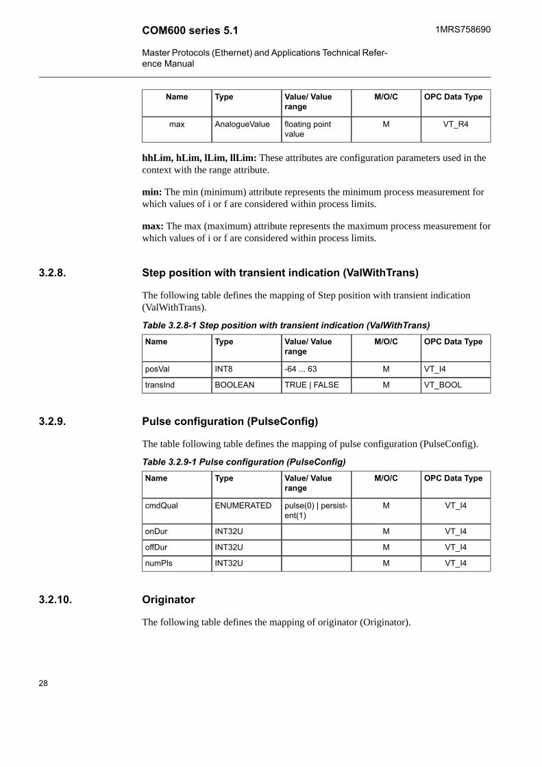
Step position with transient indication (ValWithTrans)3.2.8.
The following table defines the mapping of Step position with transient indication(ValWithTrans).
Table 3.2.8-1 Step position with transient indication (ValWithTrans)OPC Data TypeM/O/CValue/ Value
rangeTypeName
VT_I4M-64 ... 63INT8posVal
VT_BOOLMTRUE | FALSEBOOLEANtransInd
Pulse configuration (PulseConfig)3.2.9.
The table following table defines the mapping of pulse configuration (PulseConfig).
Table 3.2.9-1 Pulse configuration (PulseConfig)OPC Data TypeM/O/CValue/ Value
rangeTypeName
VT_I4Mpulse(0) | persist-ent(1)
ENUMERATEDcmdQual
VT_I4MINT32UonDur
VT_I4MINT32UoffDur
VT_I4MINT32UnumPls
Originator3.2.10.
The following table defines the mapping of originator (Originator).
28
1MRS758690COM600 series 5.1
Master Protocols (Ethernet) and Applications Technical Refer-ence Manual

Table 3.2.10-1 OriginatorOPC Data TypeM/O/CValue/ Value
rangeTypeName
VT_I4Mnot-supported(0)| bay-control(1) |station-control(2)| remote-con-trol(3) | automatic-bay(4) | auto-matic-station(5) |automatic-remote(6) | main-tenance(7) | pro-cess(8)
ENUMERATEDorCat
VT_BSTRMTRUE | FALSEOCTETSTRING64
orident
Unit3.2.11.
The following table defines the mapping of unit (Unit).
Table 3.2.11-1 UnitOPC Data TypeM/O/CValue/ Value
rangeTypeName
VT_I4MENUMERATEDSIUnit
VT_I4OENUMERATEDmultiplier
Vector3.2.12.
The following table defines the mapping of vector (Vector).
Table 3.2.12-1 VectorOPC Data TypeM/O/CValue/ Value
rangeTypeName
VT_R4Mfloating pointvalue
AnalogueValuemag
VT_R4Ofloating pointvalue
AnalogueValueang
TimeStamp3.2.13.
The timestamp OPC attributes are presented as OPC type VT_DATE. It is implementedusing an 8-byte floating-point number. Days are represented by whole number increments
29
COM600 series 5.11MRS758690
Master Protocols (Ethernet) and Applications Technical Refer-ence Manual

starting with 30 December 1899, midnight as time zero. Hour values are expressed asthe absolute value of the fractional part of the number.
AbbCommandBitmask3.2.14.
The following table defines the mapping of AbbCommandBitmask. This ABB-specificcontrol value is a bitmask value of a command to a device. This value is applicable toABB extension control attributes.
Table 3.2.14-1 AbbCommandBitmaskBit PositionM/O/CValue/ Value
rangeTypeName
0MFALSE (0) |TRUE (1)
1bitNormalControl
1MFALSE (0) |TRUE (1)
1bitInterlockOverride
2MFALSE (0) |TRUE (1)
1bitSynchrocheck-Override
3MFALSE (0) |TRUE (1)
1bitTestCommand
4-7Mnot-supported(0)| bay-control(1) |station-control(2)| remote-con-trol(3) | automatic-bay(4) | auto-matic-station(5) |automatic-remote(6) | main-tenance(7) | pro-cess(8)
4bitOriginator
8-31MnbitControlValue
NormalControl: True = normal operation, false = inverse operation (for example, On> Off).
InterlockOverride: True = interlockcheck > false
SynchrocheckOverride : True = syncrocheck > false
TestCommand: True = test command
Originator: Command originator (= Originator.orCat)
30
1MRS758690COM600 series 5.1
Master Protocols (Ethernet) and Applications Technical Refer-ence Manual

Common data class specifications for status information3.2.15.
Single point status (SPS)3.2.15.1.
The following table defines the common data class of single point status.
Table 3.2.15.1-1 Single point status (SPS)OPC DataType
M/OValue/ Valuerange
FCTypeName
VT_BOOLMTRUE |FALSE
STBOOLEANstVal
VT_I4MSTQualityq
VT_DATEMSTTimeStampt
VT_BOOLOSVBOOLEANsubEna
VT_BOOLOTRUE |FALSE
SVBOOLEANsubVal
VT_I4OSVQualitysubQ
VT_BSTROSVVISIBLESTRING64
subID
VT_BSTROTextDCVISIBLESTRING64
d
VT_BSTRODCUNICODESTRING255
dU
VT_BSTROEXVISIBLESTRING255
cdcNs
VT_BSTROEXVISIBLESTRING255
cdcName
VT_BSTROEXVISIBLESTRING255
dataNs
Double point status (DPS)3.2.15.2.
The following table defines the common data class of double point status.
Table 3.2.15.2-1 Double point status (DPS)OPC DataType
M/OValue/ Valuerange
FCTypeName
VT_I4Mintermediate-state (0) | off(1) | on (2) |bad-state (3)
STCODEDENUM
stVal
VT_I4MSTQualityq
31
COM600 series 5.11MRS758690
Master Protocols (Ethernet) and Applications Technical Refer-ence Manual

OPC DataType
M/OValue/ Valuerange
FCTypeName
VT_DATEMSTTimeStampt
VT_BOOLOSVBOOLEANsubEna
VT_I4Ointermediate-state (0) | off(1) | on (2) |bad-state (3)
SVCODEDENUM
subVal
VT_I4OSVQualitysubQ
VT_BSTROSVVISIBLESTRING64
subID
VT_BSTROTextDCVISIBLESTRING255
d
VT_BSTRODCUNICODESTRING255
dU
VT_BSTROEXVISIBLESTRING255
cdcNs
VT_BSTROEXVISIBLESTRING255
cdcName
VT_BSTROEXVISIBLESTRING255
dataNs
Integer status (INS)3.2.15.3.
The following table defines the common data class of integer status.
Table 3.2.15.3-1 Integer status (INS)OPC DataType
M/OValue/ Valuerange
FCTypeName
VT_I4MSTINT32stVal
VT_I4MSTQualityq
VT_DATEMSTTimeStampt
VT_BOOLOSVBOOLEANsubEna
VT_I4OSVINT32subVal
VT_I4OSVQualitysubQ
VT_BSTROSVVISIBLESTRING64
subID
VT_BSTRODCVISIBLESTRING255
d
VT_BSTRODCUNICODESTRING255
dU
32
1MRS758690COM600 series 5.1
Master Protocols (Ethernet) and Applications Technical Refer-ence Manual

OPC DataType
M/OValue/ Valuerange
FCTypeName
VT_BSTROEXVISIBLESTRING255
cdcNs
VT_BSTROEXVISIBLESTRING255
cdcName
VT_BSTROEXVISIBLESTRING255
dataNs
Enumerated Status (ENS)3.2.15.4.
OPC datatype
M/OValue/Valuerange
FCTypeName
MSTENUMER-ATED
stVal
VT_I4MSTQualityq
VT_I4MSTTimestampt
VT_BOOLOSVBOOLEANsubEna
VT_I4OSVINT32subVal
VT_I4OSVQualitysubQ
VT_BSTROTextSVVISIBLESTRING64
subID
VT_BSTROTextDCVISIBLESTRING 255
d
VT_BSTRODCUNICODESTRING 255
dU
VT_BSTROEXVISIBLESTRING 255
cdcNs
VT_BSTROEXVISIBLESTRING 255
cdcName
VT_BSTROEXVISIBLESTRING 255
dataNs
Protection activation information (ACT)3.2.15.5.
The following table defines the common data class of protection activation information.
Table 3.2.15.5-1 Protection activation information (ACT)OPC DataType
M/OValue/ Valuerange
FCTypeName
VT_BOOLMSTBOOLEANgeneral
33
COM600 series 5.11MRS758690
Master Protocols (Ethernet) and Applications Technical Refer-ence Manual

OPC DataType
M/OValue/ Valuerange
FCTypeName
VT_BOOLOSTBOOLEANphsA
VT_BOOLOSTBOOLEANphsB
VT_BOOLOSTBOOLEANphsC
VT_BOOLOSTBOOLEANneut
VT_I4MSTQualityq
VT_DATEMSTTimeStampt
VT_DATEOCFTimeStampoperTm
VT_BSTROTextDCVISIBLESTRING255
d
VT_BSTRODCUNICODESTRING255
dU
VT_BSTROEXVISIBLESTRING255
cdcNs
VT_BSTROEXVISIBLESTRING255
cdcName
VT_BSTROEXVISIBLESTRING255
dataNs
Directional protection activation information (ACD)3.2.15.6.
The following table defines the common data class of directional protection activationinformation.
Table 3.2.15.6-1 Directional protection activation information (ACD)OPC DataType
M/OValue/ Valuerange
FCTypeName
VT_BOOLMSTBOOLEANgeneral
Munknown (3) |forward (1) |backward (2)
STENUMER-ATED
dirGeneral
VT_BOOLOSTBOOLEANphsA
Ounknown (3) |forward (1) |backward (2)
STENUMER-ATED
dirPhsA
VT_BOOLOSTBOOLEANphsB
Ounknown (3) |forward (1) |backward (2)
STENUMER-ATED
dirPhsB
VT_BOOLOSTBOOLEANphsC
34
1MRS758690COM600 series 5.1
Master Protocols (Ethernet) and Applications Technical Refer-ence Manual

OPC DataType
M/OValue/ Valuerange
FCTypeName
Ounknown (3) |forward (1) |backward (2)
STENUMER-ATED
dirPhsC
VT_BOOLOSTBOOLEANneut
Ounknown (3) |forward (1) |backward (2)
STENUMER-ATED
dirNeut
VT_I4MSTQualityq
VT_DATEMSTTimeStampt
VT_BSTROTextDCVISIBLESTRING255
d
VT_BSTRODCUNICODESTRING255
dU
VT_BSTROEXVISIBLESTRING255
cdcNs
VT_BSTROEXVISIBLESTRING255
cdcName
VT_BSTROEXVISIBLESTRING255
dataNs
Security violation counter (SEC)3.2.15.7.
The following table defines the common data class of security violation counting.
Table 3.2.15.7-1 Security violation counting (SEC)OPC DataType
M/OValue/ Valuerange
FCTypeName
VT_I4MSTINT32Ucnt
VT_I4Munknown (0) |critical (1) |major (2) |minor (3) |warning (4)
STENUMER-ATED
sev
VT_DATEMSTTimeStampt
VT_BSTROSTOCTETSTRING64
addr
VT_BSTROSTVISIBLESTRING64
addInfo
VT_BSTROTextDCVISIBLESTRING255
d
35
COM600 series 5.11MRS758690
Master Protocols (Ethernet) and Applications Technical Refer-ence Manual
OPC DataType
M/OValue/ Valuerange
FCTypeName
VT_BSTRODCUNICODESTRING255
dU
VT_BSTROEXVISIBLESTRING255
cdcNs
VT_BSTROEXVISIBLESTRING255
cdcName
VT_BSTROEXVISIBLESTRING255
dataNs
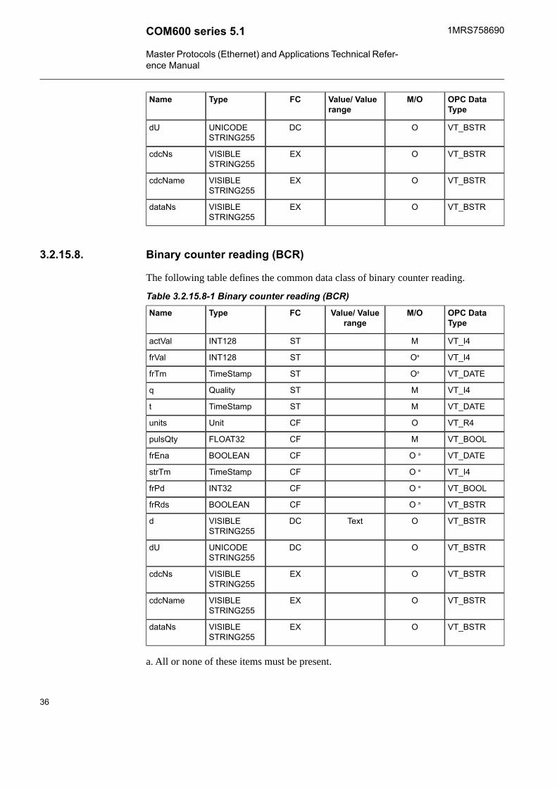
Binary counter reading (BCR)3.2.15.8.
The following table defines the common data class of binary counter reading.
Table 3.2.15.8-1 Binary counter reading (BCR)OPC DataType
M/OValue/ Valuerange
FCTypeName
VT_I4MSTINT128actVal
VT_I4OaSTINT128frVal
VT_DATEOaSTTimeStampfrTm
VT_I4MSTQualityq
VT_DATEMSTTimeStampt
VT_R4OCFUnitunits
VT_BOOLMCFFLOAT32pulsQty
VT_DATEO aCFBOOLEANfrEna
VT_I4O aCFTimeStampstrTm
VT_BOOLO aCFINT32frPd
VT_BSTRO aCFBOOLEANfrRds
VT_BSTROTextDCVISIBLESTRING255
d
VT_BSTRODCUNICODESTRING255
dU
VT_BSTROEXVISIBLESTRING255
cdcNs
VT_BSTROEXVISIBLESTRING255
cdcName
VT_BSTROEXVISIBLESTRING255
dataNs
a. All or none of these items must be present.
36
1MRS758690COM600 series 5.1
Master Protocols (Ethernet) and Applications Technical Refer-ence Manual

Common data class specifications for measured information3.2.16.
Measured value (MV)3.2.16.1.
The following table defines the common data class of measured value.
Table 3.2.16.1-1 Measured value (MV)OPC DataType
M/OValue/ Valuerange
FCTypeName
VT_R4OMXAnalogue-Value
instMag
VT_R4MMXAnalogue-Value
mag
VT_I4Onormal (0) |high (1) | low(2) | high-high(3) | low-low(4) | ...
MXENUMER-ATED
range
VT_I4MMXQualityq
VT_DATEMMXTimeStampt
VT_BOOLOSVBOOLEANsubEna
VT_R4OSVAnalogue-Value
subVal
VT_I4OSVQualitysubQ
VT_BSTROSVVISIBLESTRING64
subID
OCFUnitunits
VT_I4O0...100 000CFINT32Udb
VT_I4O0...100 000CFINT32UzeroDb
OCFScaledValue-Config
sVC
OCFRangeConfigrangeC
VT_I4OCFINT32UsmpRate
VT_BSTROTextDCVISIBLESTRING255
d
VT_BSTRODCUNICODESTRING255
dU
VT_BSTROEXVISIBLESTRING255
cdcNs
VT_BSTROEXVISIBLESTRING255
cdcName
37
COM600 series 5.11MRS758690
Master Protocols (Ethernet) and Applications Technical Refer-ence Manual

OPC DataType
M/OValue/ Valuerange
FCTypeName
VT_BSTROEXVISIBLESTRING255
dataNs
Complex measured value (CMV)3.2.16.2.
The following table defines the common data class of measured value.
Table 3.2.16.2-1 Complex measured value (CMV)OPC DataType
M/OValue/ Valuerange
FCTypeName
OMXVectorinstCVal
MMXVectorcVal
VT_I4Onormal (0) |high (1) | low(2) | high-high(3) | low-low(4) | ...
MXENUMER-ATED
range
VT_I4MMXQualityq
VT_DATEMMXTimeStampt
VT_BOOLOSVBOOLEANsubEna
OSVVectorsubVal
VT_I4OSVQualitysubQ
VT_BSTROSVVISIBLESTRING64
subID
OCFUnitunits
VT_I4O0...100 000CFINT32Udb
VT_I4O0...100 000CFINT32UzeroDb
OCFRangeConfigrangeC
OScaledValue-Config
magSVC
OScaledValue-Config
angSVC
VT_I4OV | A | other ...CFENUMER-ATED
angRef
VT_I4OCFINT32UsmpRate
VT_BSTROTextDCVISIBLESTRING255
d
VT_BSTRODCUNICODESTRING255
dU
38
1MRS758690COM600 series 5.1
Master Protocols (Ethernet) and Applications Technical Refer-ence Manual

OPC DataType
M/OValue/ Valuerange
FCTypeName
VT_BSTROEXVISIBLESTRING255
cdcNs
VT_BSTROEXVISIBLESTRING255
cdcName
VT_BSTROEXVISIBLESTRING255
dataNs
Sampled value (SAV)3.2.16.3.
The following table defines the common data class of sampled value.
Table 3.2.16.3-1 Sampled value (SAV)OPC DataType
M/OValue/ Valuerange
FCTypeName
VT_R4MMXAnalogue-Value
instMag
VT_I4MMXQualityq
VT_DATEMMXTimeStampt
OCFUnitunits
OCFScaledValue-Config
sVC
VT_R4OCFAnalogue-Value
min
VT_R4OCFAnalogue-Value
max
VT_BSTROTextDCVISIBLESTRING255
d
VT_BSTRODCUNICODESTRING255
dU
VT_BSTROEXVISIBLESTRING255
cdcNs
VT_BSTROEXVISIBLESTRING255
cdcName
VT_BSTROEXVISIBLESTRING255
dataNs
39
COM600 series 5.11MRS758690
Master Protocols (Ethernet) and Applications Technical Refer-ence Manual

WYE3.2.16.4.
The following table defines the common data class of WYE. This class is a collectionof simultaneous measurements of values in a three phase system that represent phase toground values.
Table 3.2.16.4-1 WYEOPC DataType
M/OValue/ Valuerange
FCTypeName
OaMXCMVphsA
OaMXCMVphsB
OaMXCMVphsC
OaMXCMVneut
OaMXCMVnet
OaMXCMVres
VT_I4OVa (0) | Vb (1)| Vc (2) | Aa(3) | Ab (4) |Ac (5) | Vab(6) | Vbc (7) |Vca (8) |Vother (9) |Aother (10)
CFENUMER-ATEDe
angRef
VT_BSTROTextDCVISIBLESTRING255
d
VT_BSTRODCUNICODESTRING255
dU
VT_BSTROEXVISIBLESTRING255
cdcNs
VT_BSTROEXVISIBLESTRING255
cdcName
VT_BSTROEXVISIBLESTRING255
dataNs
a. One or more of these items (1 - 6) must be present.
Delta (DEL)3.2.16.5.
The following table defines the common data class of delta. This class is a collection ofmeasurements of values in a three phase system that represent phase to phase values.
40
1MRS758690COM600 series 5.1
Master Protocols (Ethernet) and Applications Technical Refer-ence Manual

Table 3.2.16.5-1 Delta (DEL)OPC DataType
M/OValue/ Valuerange
FCTypeName
O aMXCMVphsAB
O aMXCMVphsBC
O aMXCMVphsCA
VT_I4OVa (0) | Vb (1)| Vc (2) | Aa(3) | Ab (4) |Ac (5) | Vab(6) | Vbc (7) |Vca (8) |Vother (9) |Aother (10)
CFENUMER-ATED
angRef
VT_BSTROTextDCVISIBLESTRING255
d
VT_BSTRODCUNICODESTRING255
dU
VT_BSTROEXVISIBLESTRING255
cdcNs
VT_BSTROEXVISIBLESTRING255
cdcName
VT_BSTROEXVISIBLESTRING255
dataNs
a. One or more of these groups (1 - 3) must be present.
Sequence (SEQ)3.2.16.6.
The following table defines the common data class of sequence.
Table 3.2.16.6-1 Sequence (SEQ)OPC DataType
M/OValue/ Valuerange
FCTypeName
O aMXCMVc1
O aMXCMVc2
O aMXCMVc3
VT_I4Opos-neg-zero(0) | dir-quad-zero (1)
CFENUMER-ATED
seqT
VT_I4A (0) | B (1) |C (2) | ...
CFENUMER-ATED
phsRef
41
COM600 series 5.11MRS758690
Master Protocols (Ethernet) and Applications Technical Refer-ence Manual

OPC DataType
M/OValue/ Valuerange
FCTypeName
VT_BSTROTextDCVISIBLESTRING255
d
VT_BSTRODCUNICODESTRING255
dU
VT_BSTROEXVISIBLESTRING255
cdcNs
VT_BSTROEXVISIBLESTRING255
cdcName
VT_BSTROEXVISIBLESTRING255
dataNs
a. One or more of these groups (1 - 3) must be present.
Common data class specifications for controllable statusinformation
3.2.17.
Controllable single point (SPC)3.2.17.1.
The following table defines the common data class of controllable single point.
Table 3.2.17.1-1 Controllable single point (SPC)OPC DataType
M/OValue/ Valuerange
FCTypeName
VT_I4Refer to3.2.22, Applica-tion errorcodes
ApplicationErr-orCode
lastApplError
VT_BOOLMoff (FALSE) |on (TRUE)
COBOOLEANctlVal
VT_DATEOCOTimeStampoperTm
CO, STOriginatororigin
VT_I4O0..255CO, STINT8UctlNum
VT_BOOLMFALSE |TRUE
STBOOLEANstVal
VT_I4MSTQualityq
VT_DATEMSTTimeStampt
VT_BOOLOFALSE |TRUE
STBOOLEANstSeld
VT_BOOLOSVBOOLEANsubEna
42
1MRS758690COM600 series 5.1
Master Protocols (Ethernet) and Applications Technical Refer-ence Manual

OPC DataType
M/OValue/ Valuerange
FCTypeName
VT_BOOLOFALSE |TRUE
SVBOOLEANsubVal
VT_I4OSVQualitysubQ
VT_BSTROSVVISIBLESTRIN64
subID
OCFPulseConfigpulseConfig
VT_I4MStatus-only (0)| direct-with-normal-secur-ity (1) | sbo-with-normal-security (2) |direct-with-enhanced-security (3) |sbo-with-enhanced-security (4)
CFENUMER-ATED
ctlModel
VT_I4OCFINT32UsboTimeout
VT_I4Ooperate-once(0) | operate-many (1)
CFENUMER-ATED
sboClass
VT_BSTROTextDCVISIBLESTRING255
d
VT_BSTRODCUNICODESTRING255
dU
VT_BSTROEXVISIBLESTRING255
cdcNs
VT_BSTROEXVISIBLESTRING255
cdcName
VT_BSTROEXVISIBLESTRING255
dataNs
Mapping of controls
Direct Control with Normal Security: ctlVal: MMS Write.request to Oper structure with value.
SBO with Normal Security:• ctlVal: MMS Write.request to ctlVal with value. IEC 61850 OPC Server will do the
select before operate.
Direct Control with Enhanced Security:• tlVal: MMS Write.request to Oper structure with value.
43
COM600 series 5.11MRS758690
Master Protocols (Ethernet) and Applications Technical Refer-ence Manual

SBO with Enhanced Security:• ctlVal: MMS Write.request to ctlVal with value. IEC 61850 OPC Server will do the
select before operate.
Controllable double point (DPC)3.2.17.2.
The following table defines the common data class of controllable double point.
Table 3.2.17.2-1 Controllable double point (DPC)OPC DataType
M/OValue/ Valuerange
FCTypeName
VT_I4MAbbCommand-Bitmask
ctlSelOn
VT_I4MAbbCommand-Bitmask
ctlSelOff
VT_I4MAbbCommand-Bitmask
ctlOperOn
VT_I4MAbbCommand-Bitmask
ctlOperOff
VT_I4MAbbCommand-Bitmask
ctlCan
VT_I4MAbbCommand-Bitmask
ctlOper
VT_I4Refer to3.2.22, Applica-tion errorcodes
ApplicationErr-orCode
lastApplError
VT_BOOLMoff (FALSE) |on (TRUE)
COBOOLEANctlVal
VT_DATEOCOTimeStampoperTm
OCO, STOriginatororigin
VT_I4O0..255CO, STINT8UctlNum
VT_I1Mintermediate-state (0) | off(1) | on (2) |bad-state (3)
STCODEDENUM
stVal
VT_I4MSTQualityq
VT_DATEMSTTimeStampt
VT_BOOLOFALSE |TRUE
STBOOLEANstSeld
VT_BOOLOSVBOOLEANsubEna
44
1MRS758690COM600 series 5.1
Master Protocols (Ethernet) and Applications Technical Refer-ence Manual

OPC DataType
M/OValue/ Valuerange
FCTypeName
VT_I1Ointermediate-state (0) | off(1) | on (2) |bad-state (3)
SVCPTsubVal
VT_I4OSVQualitysubQ
VT_BSTROSVVISIBLESTRING64
subID
OCFPulseConfigpulseConfig
VT_I4MStatus-only (0)| direct-with-normal-secur-ity (1) | sbo-with-normal-security (2) |direct-with-enhanced-security (3) |sbo-with-enhanced-security (4)
CFENUMER-ATED
ctlModel
VT_I4OCFINT32UsboTimeout
VT_I4Ooperate-once(0) | operate-many (1)
CFENUMER-ATED
sboClass
VT_BSTROTextDCVISIBLESTRING255
d
VT_BSTRODCUNICODESTRING255
dU
VT_BSTROEXVISIBLESTRING255
cdcNs
VT_BSTROEXVISIBLESTRING255
cdcName
VT_BSTROEXVISIBLESTRING255
dataNs
ctlOperOn: This attribute shall determine the control activity operation in directionOn/Close.
ctlOperOff: This attribute shall determine the control activity operation in directionOff/Open.
ctlSelOn: This attribute shall determine the selection with direction On/Close.
ctlSelOff; This attribute shall determine the selection with direction Off/Open.
45
COM600 series 5.11MRS758690
Master Protocols (Ethernet) and Applications Technical Refer-ence Manual

ctlCan: This attribute shall determine the cancellation of the selection
ctlOper: This attribute shall determine the selection with direction (direction got fromprevious select). Only applicable for controls with SBO.
Mapping of controls
Direct Control with Normal Security:• ctlSelOn: (not used)• ctlSelOff: (not used)• ctlOperOn: MS Write.request to Oper structure with value ON.• ctlOperOff: MMS Write.request to Oper structure with value OFF.• ctlCan: (not used)• ctlOper: (not used)
The ctlSelOn, ctlSelOff, ctlCan, selCause, cmdTermCause, stSeld and the bits in Con-trolValues are not applicable.
SBO with Normal Security:• ctlSelOn: MMS Read.request to SBO structure (to perform select).• ctlSelOff: MMS Read.request to SBO structure (to perform select).• ctlOperOn: MMS Write.request to Oper structure with value ON (to operate).• ctlOperOff: MMS Write.request to Oper structure with value OFF (to operate).• ctlCan: MMS Write.request ro Cancel structure• ctlOper: MMS Write.request to Oper structure with value ON/OFF according to
previous direction of select.
Direct Control with Enhanced Security:• ctlSelOn: (not used)• ctlSelOff: (not used)• ctlOperOn: MMS Write.request to Oper structure with value ON.• ctlOperOff: MMS Write.request to Oper structure with value OFF.• ctlCan: MMS Write.request ro Cancel structure• ctlOper: (not used)
SBO with Enhanced Security:• ctlSelOn: MMS Read.request to SBOw structure.• ctlSelOff: MMS Read.request to SBOw structure.• ctlOperOn: MMS Write.request to Oper structure with value ON.• ctlOperOff: MMS Write.request to Oper structure with value OFF.• ctlCan: MMS Write.request ro Cancel structure• ctlOper: MMS Write.request to Oper structure with value ON/OFF according to
previous direction of select.
46
1MRS758690COM600 series 5.1
Master Protocols (Ethernet) and Applications Technical Refer-ence Manual

Controllable integer status (INC)3.2.17.3.
The following table defines the common data class of controllable integer status.
Table 3.2.17.3-1 Controllable integer status (INC)OPC DataType
M/OValue/ Valuerange
FCTypeName
VT_I4Refer to3.2.22, Applica-tion errorcodes
ApplicationErr-orCode
lastApplError
VT_I4MCOINT32ctlVal
VT_DATEOCOTimeStampoperTm
VT_I4OENUMER-ATED
orCat
VT_BSTROOCTETSTRING64
orIdent
VT_I4O0..255CO, STINT8UctlNum
VT_I4MSTINT32stVal
VT_I4MSTQualityq
VT_DATEMSTTimeStampt
VT_BOOLOFALSE |TRUE
STBOOLEANstSeld
VT_BOOLOSVBOOLEANsubEna
VT_I4OSVINT32subVal
VT_I4OSVQualitysubQ
VT_BSTROTextSVVISIBLESTRING64
subID
VT_I4MStatus-only (0)| direct-with-normal-secur-ity (1) | sbo-with-normal-security (2) |direct-with-enhanced-security (3) |sbo-with-enhanced-security (4)
CFENUMER-ATED
ctlModel
VT_I4OCFINT32UsboTimeout
VT_I4Ooperate-once(0) | operate-many (1)
CFENUMER-ATED
sboClass
VT_I4OCFINT32minVal
47
COM600 series 5.11MRS758690
Master Protocols (Ethernet) and Applications Technical Refer-ence Manual

OPC DataType
M/OValue/ Valuerange
FCTypeName
VT_I4OCFINT32maxVal
VT_I4O1 ... (maxVal -minVal)
CFINT32UstepSize
VT_BSTROTextDCVISIBLESTRING255
d
VT_BSTRODCUNICODESTRING255
dU
VT_BSTROEXVISIBLESTRING255
cdcNs
VT_BSTROEXVISIBLESTRING255
cdcName
VT_BSTROEXVISIBLESTRING255
dataNs
Mapping of controls
Direct Control with Normal Security:• ctlVal: MMS Write.request to Oper structure with value.
SBO with Normal Security:• ctlVal: MMS Write.request to Oper structure with value. IEC 61850 OPC Server
will do the select before operate.
Direct Control with Enhanced Security:• ctlVal: MMS Write.request to Oper structure with value.
SBO with Enhanced Security:• ctlVal: MMS Write.request to Oper structure with value. IEC 61850 OPC Server
will do the select before operate.
Controllable Enumerated Status (ENC)3.2.17.4.
OPC datatype
M/OValue/Valuerange
FCTypeName
VT_I4MRefer to 5.2.22Applicationerror codes
ApplicationErr-orCode
lastApplError
VT_I4MCOENUMER-ATED
ctlVal
VT_DATEOCOTimestampoperTm
48
1MRS758690COM600 series 5.1
Master Protocols (Ethernet) and Applications Technical Refer-ence Manual

OPC datatype
M/OValue/Valuerange
FCTypeName
VT_I4OENUMER-ATED
orCat
VT_BSTROOCTETSTRING64
orIdent
VT_I4O0..255CO, STINT8UctlNum
VT_I4MSTENUMER-ATED
stVal
VT_I4MSTQualityq
VT_I4MSTTimestampt
VT_BOOLOFALSE|TRUESTBOOLEANstSeld
VT_BOOLOSVBOOLEANsubEna
VT_I4OSVINT32subVal
VT_I4OSVQualitysubQ
VT_BSTROTextSVVISIBLESTRING64
subID
VT_I4MStatus-only(0)|direct-with-normal-security(1)|
sbo-with-nor-mal-security(2)| direct-with-enhanced-security(3)|sbo-with-
enhanced-security(4)
CFENUMER-ATED
ctlModel
VT_I4OCFINT32UsboTimeout
VT_I4OOperate-once(0) | oper-ate-many(1)
CFENUMER-ATED
sboClass
VT_I4OCFINT32UoperTimeout
VT_BSTROTextDCVISIBLESTRING 255
d
VT_BSTRODCUNICODESTRING 255
dU
VT_BSTROEXVISIBLESTRING 255
cdcNs
VT_BSTROEXVISIBLESTRING 255
cdcName
49
COM600 series 5.11MRS758690
Master Protocols (Ethernet) and Applications Technical Refer-ence Manual

OPC datatype
M/OValue/Valuerange
FCTypeName
VT_BSTROEXVISIBLESTRING 255
dataNs
Binary controlled step position information (BSC)3.2.17.5.
The following table defines the common data class of binary controlled step positioninformation.
Table 3.2.17.5-1 Binary controlled step position information (BSC)OPC DataType
M/OValue/ Valuerange
FCTypeName
VT_I4Refer to3.2.22, Applica-tion errorcodes
Application-Erro rCode
lastApplError
VT_I4Mstop (0) | lower(1) | higher (2)| reserved (3)
ENUMER-ATED
ctlVal
VT_DATEOCOTimeStampoperTm
VT_I4Onot-supported| bay-control |station-control| remote-con-trol | auto-matic-bay |automatic-sta-tion | auto-matic-remote |maintenance |process
ENUMER-ATED
orCat
VT_BSTROCTETSTRING64
orIdent
VT_I4O0..255CO, STINT8UctlNum
VT_I4MSTINT8valWTr.posVal
VT_BOOLMSTBOOLEANval-WTr.transInd
VT_I4MSTQualityq
VT_DATEMSTTimeStampt
VT_I4MFALSE |TRUE
STBOOLEANstSeld
VT_BOOLOSTQualityq
VT_DATEMSTTimeStampt
50
1MRS758690COM600 series 5.1
Master Protocols (Ethernet) and Applications Technical Refer-ence Manual

OPC DataType
M/OValue/ Valuerange
FCTypeName
VT_BOOLOFALSE |TRUE
STBOOLEANstSeld
VT_BOOLOSVBOOLEANsubEna
VT_I4OSVINT32subVal
VT_I4OSVQualitysubQ
VT_BSTROTextSVVISIBLESTRING64
subID
O
VT_I4MStatus-only (0)| direct-withnor-mal- security(1) | sbo-with-normal- secur-ity (2) | direct-withenhanced-security (3) |sbo-withen-hanced- secur-ity (4)
CFENUMER-ATED
ctlModel
VT_I4OCFINT32UsboTimeout
VT_I4Ooperate-once(0) | operate-many (1)
CFENUMER-ATED
sboClass
VT_I4OCFINT8minVal
VT_I4OCFINT8maxVal
VT_I4O1 ... (maxVal -minVal)
CFINT8stepSize
VT_BSTROTextDCVISIBLESTRING255
d
VT_BSTRODCUNICODESTRING255
dU
VT_BSTROEXVISIBLESTRING255
cdcNs
VT_BSTROEXVISIBLESTRING255
cdcName
VT_BSTROEXVISIBLESTRING255
dataNs
Mapping of controls
Direct Control with Normal Security:• ctlVal: MMS Write.request to Oper structure with value.
51
COM600 series 5.11MRS758690
Master Protocols (Ethernet) and Applications Technical Refer-ence Manual

SBO with Normal Security:• ctlVal: MMS Write.request to Oper structure with value.
IEC 61850 OPC Server will do the select before operate.
Direct Control with Enhanced Security:• ctlVal: MMS Write.request to Oper structure with value.
SBO with Enhanced Security:• ctlVal: MMS Write.request to Oper structure with value.
IEC 61850 OPC Server will do the select before operate.
Integer controlled step position information (ISC)3.2.17.6.
The following table defines the common data class of integer controlled step positioninformation.
Table 3.2.17.6-1 Integer controlled step position information (ISC)OPC DataType
M/OValue/ Valuerange
FCTypeName
VT_I4Refer to3.2.22, Applica-tion errorcodes
ApplicationErr-orCode
lastApplError
VT_I4M-64 … 63COINT8ctlVal
VT_DATEOCOTimeStampoperTm
VT_I4Onot-supported| bay-control |station-control| remote-con-trol | auto-matic-bay |automatic-sta-tion | auto-matic-remote |maintenance |process
ENUMER-ATED
orCat
VT_BSTROOCTETSTRING64
orIdent
VT_I4O0..255CO, STINT8UctlNum
VT_I4MSTINT8valWTr.posVal
VT_BOOLMSTBOOLEANval-WTr.transInd
VT_I4MSTQualityq
VT_DATEMSTTimeStampt
VT_BOOLOFALSE |TRUE
STBOOLEANstSeld
52
1MRS758690COM600 series 5.1
Master Protocols (Ethernet) and Applications Technical Refer-ence Manual

OPC DataType
M/OValue/ Valuerange
FCTypeName
O
VT_BOOLOSVBOOLEANsubEna
VT_I4OSVINT32subVal
VT_I4OSVQualitysubQ
VT_BSTROTextSVVisibleStringsubID
O
VT_I4MStatus-only (0)| direct-with-normal-secur-ity (1) | sbo-with-normal-security (2) |direct-with-enhanced-security (3) |sbo-with-enhanced-security (4)
CFENUMER-ATED
ctlModel
VT_I4OCFINT32UsboTimeout
VT_I4Ooperate-once(0) | operate-many (1)
CFENUMER-ATED
sboClass
VT_I4OCFINT8minVal
VT_14OCFINT8maxVal
VT_14O1 ... (maxVal -minVal)
CFINT8stepSize
VT_BSTROTextDCVISIBLESTRING255
d
VT_BSTRODCUNICODESTRING255
dU
VT_BSTROEXVISIBLESTRING255
cdcNs
VT_BSTROEXVISIBLESTRING255
cdcName
VT_BSTROEXVISIBLESTRING255
dataNs
Mapping of controls
Direct Control with Normal Security:• ctlVal: MMS Write.request to Oper structure with value.
53
COM600 series 5.11MRS758690
Master Protocols (Ethernet) and Applications Technical Refer-ence Manual
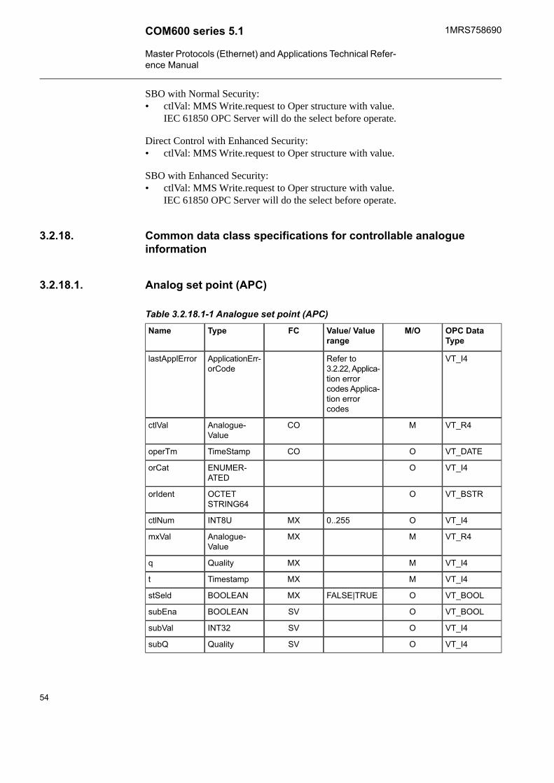
SBO with Normal Security:• ctlVal: MMS Write.request to Oper structure with value.
IEC 61850 OPC Server will do the select before operate.
Direct Control with Enhanced Security:• ctlVal: MMS Write.request to Oper structure with value.
SBO with Enhanced Security:• ctlVal: MMS Write.request to Oper structure with value.
IEC 61850 OPC Server will do the select before operate.
Common data class specifications for controllable analogueinformation
3.2.18.
Analog set point (APC)3.2.18.1.
Table 3.2.18.1-1 Analogue set point (APC)OPC DataType
M/OValue/ Valuerange
FCTypeName
VT_I4Refer to3.2.22, Applica-tion errorcodes Applica-tion errorcodes
ApplicationErr-orCode
lastApplError
VT_R4MCOAnalogue-Value
ctlVal
VT_DATEOCOTimeStampoperTm
VT_I4OENUMER-ATED
orCat
VT_BSTROOCTETSTRING64
orIdent
VT_I4O0..255MXINT8UctlNum
VT_R4MMXAnalogue-Value
mxVal
VT_I4MMXQualityq
VT_I4MMXTimestampt
VT_BOOLOFALSE|TRUEMXBOOLEANstSeld
VT_BOOLOSVBOOLEANsubEna
VT_I4OSVINT32subVal
VT_I4OSVQualitysubQ
54
1MRS758690COM600 series 5.1
Master Protocols (Ethernet) and Applications Technical Refer-ence Manual

OPC DataType
M/OValue/ Valuerange
FCTypeName
VT_BSTROTextSVVISIBLESTRING64
subID
VT_I4MStatus-only(0)|direct-with-normal-security(1)|sbo-with-nor-mal-security(2)| direct-with-enhanced-security(3)|sbo-with-enhanced-security(4)
CFENUMER-ATED
ctlModel
VT_I4OCFINT32UsboTimeout
VT_I4OOperate-once(0) | oper-ate-many(1)
CFENUMER-ATED
sboClass
OCFUnitunits
O0… 100000CFINT32Udb
OCFScaledValue-Config
sVC
OCFAnalogue-Value
minVal
OCFAnalogue-Value
maxVal
OCFAnalogue-Value
stepSize
OCFINT32UoperTimeout
VT_BSTROTextDCVISIBLESTRING 255
d
VT_BSTRODCUNICODESTRING 255
dU
VT_BSTROEXVISIBLESTRING 255
cdcNs
VT_BSTROEXVISIBLESTRING 255
cdcName
VT_BSTROEXVISIBLESTRING 255
dataNs
55
COM600 series 5.11MRS758690
Master Protocols (Ethernet) and Applications Technical Refer-ence Manual

Mapping of controls
Direct Control with Normal Security:• setMag: MMS Write.request to Oper structure with value.
SBO with Normal Security:• setMag: MMS Write.request to Oper structure with value. IEC 61850 OPC Server
will do the select before operate.
Direct Control with Enhanced Security:• setMag: MMS Write.request to Oper structure with value.
SBO with Enhanced Security:• setMag: MMS Write.request to Oper structure with value. IEC 61850 OPC Server
will do the select before operate.
Common data class specifications for status settings3.2.19.
Single point setting (SPG)3.2.19.1.
The following table defines the common data class of single point setting.
Table 3.2.19.1-1 Single point setting (SPG)OPC DataType
M/OValue/ Valuerange
FCTypeName
VT_BOOLMoff (FALSE) |on (TRUE)
SPBOOLEANsetVal
VT_BSTROTextDCVISIBLESTRING255
d
VT_BSTRODCUNICODESTRING255
dU
VT_BSTROEXVISIBLESTRING255
cdcNs
VT_BSTROEXVISIBLESTRING255
cdcName
VT_BSTROEXVISIBLESTRING255
dataNs
Integer status setting (ING)3.2.19.2.
The following table defines the common data class of integer status setting.
56
1MRS758690COM600 series 5.1
Master Protocols (Ethernet) and Applications Technical Refer-ence Manual

Table 3.2.19.2-1 Integer status setting (ING)OPC DataType
M/OValue/ Valuerange
FCTypeName
VT_I4MSPINT32setVal
VT_I4OCFINT32minVal
VT_I4OCFINT32maxVal
VT_I4O1 ... (maxVal -minVal)
CFINT32stepSize
VT_BSTROTextDCVISIBLESTRING255
d
VT_BSTRODCUNICODESTRING255
dU
VT_BSTROEXVISIBLESTRING255
cdcNs
VT_BSTROEXVISIBLESTRING255
cdcName
VT_BSTROEXVISIBLESTRING255
dataNs
Common data class specifications for analogue settings3.2.20.
Analogue setting (ASG)3.2.20.1.
The following table defines the common data class of analogue setting.
Table 3.2.20.1-1 Analogue setting (ASG)OPC DataType
M/OValue/ Valuerange
FCTypeName
VT_I4MSPAnalogue-Value
setMag
OCFUnitunits
OCFScaledValue-Config
sVC
VT_I4OCFAnalogue-Value
minVal
VT_I4OCFAnalogue-Value
maxVal
VT_I4O1 ... (maxVal -minVal)
CFAnalogue-Value
stepSize
VT_BSTROTextDCVISIBLESTRING255
d
57
COM600 series 5.11MRS758690
Master Protocols (Ethernet) and Applications Technical Refer-ence Manual

OPC DataType
M/OValue/ Valuerange
FCTypeName
VT_BSTRODCUNICODESTRING255
dU
VT_BSTROEXVISIBLESTRING255
cdcNs
VT_BSTROEXVISIBLESTRING255
cdcName
VT_BSTROEXVISIBLESTRING255
dataNs
Setting curve (CURVE)3.2.20.2.
The following table defines the common data class of setting curve.
Table 3.2.20.2-1 Setting curve (CURVE)OPC DataType
M/OValue/ Valuerange
FCTypeName
VT_I4MSPENUMER-ATED
setCharact
VT_R4OSPFLOAT32setParA
VT_R4OSPFLOAT32setParB
VT_R4OSPFLOAT32setParC
VT_R4OSPFLOAT32setParD
VT_R4OSPFLOAT32setParE
VT_R4OSPFLOAT32setParF
VT_BSTROTextDCVISIBLESTRING255
d
VT_BSTRODCUNICODESTRING255
dU
VT_BSTROEXVISIBLESTRING255
cdcNs
VT_BSTROEXVISIBLESTRING255
cdcName
VT_BSTROEXVISIBLESTRING255
dataNs
58
1MRS758690COM600 series 5.1
Master Protocols (Ethernet) and Applications Technical Refer-ence Manual

Common data class specifications for description information3.2.21.
Device name plate (DPL)3.2.21.1.
The following table defines the common data class of device name plate. Data of thiscommon data class are used to identify entities like primary equipment or physicaldevices.
Table 3.2.21.1-1 Device name plate (DPL)OPC DataType
M/OValue/ Valuerange
FCTypeName
VT_BSTRMDCVISIBLESTRING255
vendor
VT_BSTRODCVISIBLESTRING255
hwRev
VT_BSTRODCVISIBLESTRING255
swRev
VT_BSTRODCVISIBLESTRING255
serNum
VT_BSTRODCVISIBLESTRING255
model
VT_BSTRODCVISIBLESTRING255
location
VT_BSTROEXVISIBLESTRING255
cdcNs
VT_BSTREXVISIBLESTRING255
cdcName
VT_BSTROEXVISIBLESTRING255
dataNs
Logical node name plate (LPL)3.2.21.2.
The following table defines the common data class of logical node name plate. Data ofthis common data class are used to identify logical nodes.
Table 3.2.21.2-1 Logical node name plate (LPL)OPC DataType
M/OValue/ Valuerange
FCTypeName
VT_BSTRMDCVISIBLESTRING255
vendor
VT_BSTRMDCVISIBLESTRING255
hwRev
VT_BSTRMTextDCVISIBLESTRING255
d
59
COM600 series 5.11MRS758690
Master Protocols (Ethernet) and Applications Technical Refer-ence Manual

OPC DataType
M/OValue/ Valuerange
FCTypeName
VT_BSTRODCUNICODESTRING255
dU
VT_BSTRODCVISIBLESTRING255
configRev
VT_BSTROwill beincluded onlyin LLN0
EXVISIBLESTRING255
ldNs
VT_BSTROEXVISIBLESTRING255
lnNs
VT_BSTROEXVISIBLESTRING255
cdcNs
VT_BSTROEXVISIBLESTRING255
cdcName
VT_BSTROEXVISIBLESTRING255
dataNs
Application error codes3.2.22.
Command Error codes of lastApplError attribute. The attribute is valid only for commanddata classes and its value presents the status of the last command. It is updated whencommand responses are received from devices.
The status code is received by adding the additional status code to main status code.
Example: 1003 = Unknown, select failed
Table 3.2.22-1 Main status codesOK0
Unknown1000
Timeout test not ok2000
Operator test not ok3000
Table 3.2.22-2 Additional status codesUnknown0
Not supported1
Blocked by switching hierarchy2
Select failed3
Invalid position4
Position reached5
Parameter change in execution6
60
1MRS758690COM600 series 5.1
Master Protocols (Ethernet) and Applications Technical Refer-ence Manual

Step limit7
Blocked by mode8
Blocked by process9
Blocked by interlocking10
Blocked by synchrocheck11
Command already in execution12
Blocked by health13
1 of n control14
Abortion by cancel15
Time limit over16
Abortion by trip17
Object not selected18
Attributes3.3.
General information about attributes3.3.1.
In addition to attributes for process data (indications and commands), the OPC Serveralso provides some attributes for controlling the devices and retrieving status informationfrom them. These attributes are available for the OPC access client.
Server attributes3.3.2.
Table 3.3.2-1 Server attributesDescriptionValue or Value range/ DefaultName
Data type: Text
Access: Read-only
The version information of the ProtocolStack
Version informationProtocol stack ver-sion
Data type: Text
Access: Read-only
The version information of the currentconfiguration file.
Version informationConfiguration ver-sion
61
COM600 series 5.11MRS758690
Master Protocols (Ethernet) and Applications Technical Refer-ence Manual

DescriptionValue or Value range/ DefaultName
Data type: Integer
Access: No limitations
Makes it possible for clients to reset theOPC server. A reset means that the serverdisconnects all clients and reloads theconfiguration file.
When the last client is discon-nected the server usually shutsdown. The server does not shutdown if it was not started by theCOM runtime or if it is runningas a Windows service. In thatcase the configuration file is notreloaded.
By writing 1 the server is reset.
By writing 2 the log file iscleared.
Other values are currentlyignored.
Reset
Data type: Text
Access: Read-only
The file version number of the OPCserver/client exe file.
Version informationFile version
Data type: Text
Access: Read-only
The version (revision) of the package thatthe server/client belong to.
Version informationProduct version
Timesync client
Data type: Integer
Access: No limitations
Status of the integrated SNTP clients timesynchronization routine. Value is 0 whennot in use and 1 when in use. By writing0 the client is started and by writing 1 it isstopped. The client can be started only ifconfiguration parameters are given in aconfiguration file.
0 = Not in use
1 = In use
Default: 1
In use
Data type: Boolean
Access: Read-only
Status of the integrated SNTP client timesynchronization routine. Value is falsewhen synchronization is not received andtrue when synchronization received andlocal time set OK.
False = Not synchronised
True = Synchronised OK
Timesync status
Timesync server
62
1MRS758690COM600 series 5.1
Master Protocols (Ethernet) and Applications Technical Refer-ence Manual

DescriptionValue or Value range/ DefaultName
Data type: Integer
Access: No limitations
Status of the integrated SNTP servers timesynchronization routine. Value is 0 whennot in use and 1 when in use. By writing0 the client is started and by writing 1 it isstopped.
0 = Not in use
1 = In use
Default: 1
In use
Status of the integrated SNTP servers timesynchronization routine. Value is falsewhen operation fails and true when oper-ating OK.
False = Failure
True = OK
Timesync status
IEC 61850 subnetwork attributes3.3.3.
Table 3.3.3-1 IEC 61850 subnetwork attributesDescriptionValue or Value range/ DefaultName
Data type: Integer
Access: No limitations
The state of the subnetwork whether it isin use or not. When a subnetwork is notin use, no data can be transmitted on it,and no data is received from it. When asubnetwork is stopped by setting the inuse attribute to 0, all data transmission onthe subnetwork ceases and all open con-nections to the devices will be closed.Single devices in use attribute may be setto 1 and this operation also takes thesubnetwork in use. Now only the onedevice is in use. If the subnetwork in useis set to 1, the rest of the devices are takenin use. The in use attribute has no affecton devices in simulation mode.
0 = Not in use, the subnetworkcommunication is stopped
1 = In use
Default: 1
In use
Data type: Integer
Access: Read-only
Indicates the operating status of the device
89 = Initialize error
90 = Not connected
91 = Initializing
100 = Ready
101 = Suspended (=Not in use)
102 = Simulated
Object status
63
COM600 series 5.11MRS758690
Master Protocols (Ethernet) and Applications Technical Refer-ence Manual

DescriptionValue or Value range/ DefaultName
Data type: Boolean
Access: No limitations
Enables/disables diagnostic events
False = Diagnostic events dis-abled
True = Diagnostic eventsenabled
Diagnostic eventsenabled
Data Type: Integer
Access: No limitations
Sets the maximum level for events comingfrom devices. Limits the lower level eventsto pass through.
0 = Disabled
1 = Level1 (main operation anderrors)
2 = Level2 (+ time synchroniza-tion error)
3 = Level3 (+ time synchroniza-tion done)
4 = Level4
5 = Level5
Diagnostic eventslevel
Diagnostic coun-ters
Data type: Integer
Access: No limitations
Connect requests sent to devices
Sent connectionrequest
Data type: Integer
Access: No limitations
Successful connect replies from devices
Received connec-tion replies ok
Data type: Integer
Access: No limitations
Failed connect replies from devices
Received connec-tion replies error
Data type: Integer
Access: No limitations
Connections closed by IEC 61850 OPCserver
Sent connectionconcludes
Data type: Integer
Access: No limitations
Received connection concludes
Received connec-tion concludes
Data type: Integer
Access: No limitations
Connections refused and aborted bydevices
Received connec-tion aborts
64
1MRS758690COM600 series 5.1
Master Protocols (Ethernet) and Applications Technical Refer-ence Manual

DescriptionValue or Value range/ DefaultName
Data type: Integer
Access: No limitations
Request rejected by devices (usually ifdevice could not decode the request orthey do not support the used service)
Received rejects
Data type: Integer
Access: No limitations
Request sent to devices
Sent requests
Data type: Integer
Access: No limitations
Successful requests to devices (receivedsuccess responses)
Received replies ok
Data type: Integer
Access: No limitations
Failed requests to devices (received errorresponses)
Received replieserror
Data type: Integer
Access: No limitations
Variable read success responses fromdevices
Received variableread replies ok
Data type: Integer
Access: No limitations
Variable read failure responses fromdevices
Received variableread replies error
Data type: Integer
Access: No limitations
Variable write success responses fromdevices
Received variablewrite replies ok
Data type: Integer
Access: No limitations
Variable read failure responses fromdevices
Received variablewrite replies error
Data type: Integer
Access: No limitations
Information reports received from devices
Received informa-tion reports
65
COM600 series 5.11MRS758690
Master Protocols (Ethernet) and Applications Technical Refer-ence Manual

DescriptionValue or Value range/ DefaultName
Data type: Integer
Access: No limitations
Unsolicited status requests received fromdevices
Received statusrequests
IEC 61850 device attributes3.3.4.
Table 3.3.4-1 IEC 61850 device attributesDescriptionValue or Value range/ DefaultName
Data type: Integer
Access: No limitations
The operational status of the devicewhether it is in use or out of use. Takingthe device out of use with this attributestops all data communication with thedevice and closes the connection. Alloperations that would result in a dataexchange are disabled. Setting in use to1 will take the device back in use and triesto reestablish the connection to a physicaldevice. The device itself is not affected bythe attribute, only protocol stack’s imageof the device. The in use attribute has noaffect on devices in simulation mode.
0 = Out of use
1 = In use
Default: 1
In use
66
1MRS758690COM600 series 5.1
Master Protocols (Ethernet) and Applications Technical Refer-ence Manual

DescriptionValue or Value range/ DefaultName
Data type: Integer
Access: Read-only
Indicates the operating status of the device
Data type: Integer
Access: Read-only
Indicates the operating status of the device
94 = Init (checking configura-tion version for single rcb)
95 = init (checking rcb attrib-utes for single rcb)
96 = Init (reading rcb variablelist for single rcb)
97 = Init (enabling reporting forsingle rcb)
98 = Init (rcb init ok for singlercb)
100 = Ready
101 = Suspended (= not in use)
102 = Device simulated
86 = Report control block initial-ization error (restarting rcb init)
88 = Configuration version error(device is suspended)
89 = error (not specified)
90 = Device not connected
91 = Initializing
92 = Initializing rcb (after errorin reporting init or informationreport flow)
93 = Reinitialize (after reconnec-tion if init done)
Object status
Data type: Boolean
Access: Read-only
Indicates the status of the device connec-tion.
False = Device connectionsuspended
True = Device connection OK
Device connectionstatus
Data type: Boolean
Access: No limitations
Enables/disables diagnostic events
False = Diagnostic events dis-abled
True = Diagnostic eventsenabled
Diagnostic eventsenabled
67
COM600 series 5.11MRS758690
Master Protocols (Ethernet) and Applications Technical Refer-ence Manual

DescriptionValue or Value range/ DefaultName
Data Type: Integer
Access: No limitations
Sets diagnostics event level
0 = Disabled
1 = Level1 (main operation,error replies, errors)
2 = Level2 (+ InformationReports, OK replies, RCB init)
3 = Level3 (+ sent requests(connect,read,write), transpar-ent SPA messages)
4 = Level4 (+ reported localupdates)
5 = Level5 (+ reported uncon-figured updates)
Diagnostic eventslevel
Data type: Text
Access: Read-only (configuration)
IP address of the physical device
0.0.0.0 - 255.255.255.255IP address
Data type: Text
Access: Read-only
The version information of the currentconfiguration for this device.
Version informationConfiguration ver-sion
See 3.3.5, Transparent XSAT.Transparent XSAT
Diagnostic coun-ters
Data type: Integer
Access: No limitation
Connection requests sent to device
Sent connectionrequests
Data type: Integer
Access: No limitation
Success connection replies received fromdevice (connection accepted)
Received connec-tion replies ok
Data type: Integer
Access: No limitation
Failure connection replies received fromdevice (connection refused).
Received connec-tion replies error
68
1MRS758690COM600 series 5.1
Master Protocols (Ethernet) and Applications Technical Refer-ence Manual
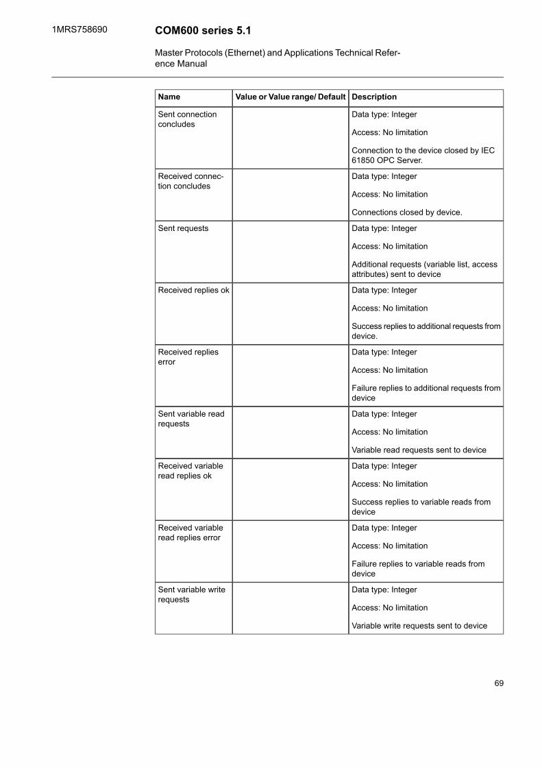
DescriptionValue or Value range/ DefaultName
Data type: Integer
Access: No limitation
Connection to the device closed by IEC61850 OPC Server.
Sent connectionconcludes
Data type: Integer
Access: No limitation
Connections closed by device.
Received connec-tion concludes
Data type: Integer
Access: No limitation
Additional requests (variable list, accessattributes) sent to device
Sent requests
Data type: Integer
Access: No limitation
Success replies to additional requests fromdevice.
Received replies ok
Data type: Integer
Access: No limitation
Failure replies to additional requests fromdevice
Received replieserror
Data type: Integer
Access: No limitation
Variable read requests sent to device
Sent variable readrequests
Data type: Integer
Access: No limitation
Success replies to variable reads fromdevice
Received variableread replies ok
Data type: Integer
Access: No limitation
Failure replies to variable reads fromdevice
Received variableread replies error
Data type: Integer
Access: No limitation
Variable write requests sent to device
Sent variable writerequests
69
COM600 series 5.11MRS758690
Master Protocols (Ethernet) and Applications Technical Refer-ence Manual

DescriptionValue or Value range/ DefaultName
Data type: Integer
Access: No limitation
Success replies to variable write fromdevice
Received variablewrite replies ok
Data type: Integer
Access: No limitation
Failure replies to variable write from device
Received variablewrite replies error
Data type: Integer
Access: No limitation
Information reports received from device
Received informa-tion reports
Data type: Integer
Access: No limitation
Successful replies to Status requestsreceived from device
Received statusreplies
Transparent XSAT3.3.5.
The Transparent XSAT attribute can be used to read and write IEC 61850 attributes,which are not configured to the OPC namespace of the IEC 61850 OPC Server. Forexample, the transparent XSAT attribute can be used for setting group controlling. TheTransparent XSAT attribute is used through an OPC client. The attribute uses the OPCdata type BSTR, which is a variant of VT_BSTR data type.
The Transparent XSAT attribute passes on request the IEC 61850 servers and theirattributes outside the IEC 61850 OPC servers namespace. The IEC 61850 OPC serverdoes not check the outgoing attributes. Therefore the IEC 61850 OPC clients which areusing the Transparent XSAT attribute know what attributes they are accessing. TheTransparent XSAT attribute only supports read and write requests.
The Transparent XSAT attribute uses synchronic data access in the IEC 61850 OPCserver. When an IEC 61850 OPC client writes a request, the IEC 61850 OPC serverparses and sends the request to the IEC 61850 server.
The Transparent XSAT attribute returns and releases the request after it has receivedreply from the IEC 61850 server. The reply is written in the Transparent XSAT attributeas an XSAT string.
70
1MRS758690COM600 series 5.1
Master Protocols (Ethernet) and Applications Technical Refer-ence Manual

XSAT Read Request
Attribute Data Type Unknown
The data type of the attribute is not known, because it is not included in the IEC 61850OPC Server configuration (SCL). The Transparent XSAT attribute asks first the requireddata type, before reading the data from an IEC 61850 server.
If the Transparent XSAT attribute receives a success message, the data type is saved. Ifthe Transparent XSAT attribute receives an error message, an XSAT error string is sentto the IEC 61850 OPC client.
The IEC 61850 OPC server request for the data type with a ReadVariableData service.The results are written in the Transparent XSAT attribute as an XSAT string. The XSATstring contains success and error messages.
Attribute Data Type Known
The attribute data type is known from a previous request or the attribute is included inthe IEC 61850 OPC Server configuration (SCL). The IEC 61850 OPC server directlyuses a ReadVariableData service to complete the request. The reply message is writtenin the Transparent XSAT attribute as an XSAT string. The XSAT string contains successand error messages.
XSAT Write Request
Attribute Data Type Unknown
The data type of the attribute is not known, because it is not included in the IEC 61850OPC Server configuration (SCL). The Transparent XSAT attribute first asks the requireddata type, before writing the data from an IEC 61850 server.
If the Transparent XSAT attribute receives a success message, the data type is saved. Ifthe Transparent XSAT attribute receives an error message, an XSAT error string is sentto the IEC 61850 OPC client.
The IEC 61850 OPC server requests for the data type with a WriteVariableData service.The results are written in the Transparent XSAT attribute as an XSAT string. The XSATstring contains success and error messages.
Attribute Data Type Known
The attribute data type is known from a previous request or the attribute is included inthe IEC 61850 OPC Server configuration (SCL). The IEC 61850 OPC server directlyuses a WriteVariableData service to complete the request. The reply message is writtenin the Transparent XSAT attribute as an XSAT string. The XSAT string contains successand error messages.’
71
COM600 series 5.11MRS758690
Master Protocols (Ethernet) and Applications Technical Refer-ence Manual

XSAT Formats
• XSAT Read RequestGetDataValue&result={name|noname}&LDInst=””&FunCon-str=””&LNName=””[&DORef=””&Attr=””]]
• XSAT Write RequestSetDataValue&LDInst=””&FunCon-str=””&LNName=””[&DORef=””[&Attr=””]]&v=””
• XSAT Read ReplySuccess with names (result=name)<?xml version="1.0"?><!DOCTYPE XSAT SYSTEM "xsat-004.dtd"><XSAT><Response><DO><LDInst>…</LDInst><LNName>…</LNName><DORef>…</DORef><At><n>…</n><v>…</v><FunConstr>…</FunConstr></At> … </DO> …</Response> </XSAT>Success without names (result=noname)<?xml version="1.0"?><!DOCTYPE XSAT SYSTEM "xsat-004.dtd"><XSAT><Response><Values> <v>…</v> … </Values></Response></XSAT>Failure<?xml version=\"1.0\"?><!DOCTYPE XSAT SYSTEM \"xsat-004.dtd\"> <XSAT><Response> <Result>failure</Result></Response></XSAT>
• XSAT Write ReplySuccess<?xml version=\"1.0\"?><!DOCTYPE XSAT SYSTEM \"xsat-004.dtd\"> <XSAT><Response> <Result>ok</Result> </Response> </XSAT>Failure<?xml version=\"1.0\"?><!DOCTYPE XSAT SYSTEM \"xsat-004.dtd\"> <XSAT><Response> <Result>failure</Result> </Response> </XSAT>EXAMPLE 1 (Read request + success reply)IEC 61850 Path:LD1$PTOC1$STRequest:GetDataValue&result=name&LDInst=LD1&LNName=PTOC1&FunConstr=STReply OK:<?xml version="1.0"?> <!DOCTYPE XSAT SYSTEM "xsat-004.dtd"> <XSAT><Response><DO><LDInst>LD1</LDInst><LNName>PTOC1</LNName><DORef>Str</DORef><At><n>general</n><v>False</v><FunConstr>ST</FunConstr></At><At><n>t</n><v>1.1.1970</v><FunConstr>ST</FunConstr></At><At><n>q</n><v>12288</v><FunConstr>ST</FunConstr></At> </DO><DO><LDInst>LD1</LDInst><LNName>PTOC1</LNName><DORef>Op</DORef><At><n>general</n><v>False</v><FunConstr>ST</FunConstr></At><At><n>t</n><v>1.1.1970</v><FunConstr>ST</FunConstr></At><At><n>q</n><v>68</v><FunConstr>ST</FunConstr></At> </DO> </Response></XSAT>EXAMPLE 2 (Write request + failure reply)IEC 61850 Path:LD1$LLN0$BR$brcbStatUrg02&RptEna
72
1MRS758690COM600 series 5.1
Master Protocols (Ethernet) and Applications Technical Refer-ence Manual

Request:SetDataValue&LDInst=LD1&LNName=LLN0&DORef=brcbStat-Urg02&Attr=RptEna&FunConstr=BR&v=FalseReply OK:<?xml version="1.0"?><!DOCTYPE XSAT SYSTEM "xsat-004.dtd"> <XSAT><Response> <Result>failure</Result> </Response> </XSAT>
IEC 61850 logical device attributes3.3.6.
Table 3.3.6-1 IEC 61850 logical device attributesDescriptionValue or Value range/ DefaultName
Data type: Text
Access: No limitations
Makes it possible to communicate withSPA unit by sending SPA message andreading the reply as text in SPA formatfrom this item. The communication ispassed through a TCP/SPA tunnel, wherethis attribute acts as an independentTCP/SPA client and is connected to aTCP/SPA server. The TCP/SPA server isthen responsible for forwarding the SPAmessages to and from the SPA devices.The SPA/TCP client handles its owncommunication separately from othercommunication. No checks are done oncommand or reply contents they are simplypassed on. This parameter is availableonly by configuration.
This attribute must be enabled by settingthe Transparent SPA Address. Forexample:
SPA address = 1
SPA command RF must we written informat RF: and sent in format 1RF:. Thereply is received in format >1D:REF543 :.
The contents of a valid SPArequest
Transparent SPA
IEC 61850 File transfer3.4.
General information about IEC 61850 File Transfer3.4.1.
This section defines how the IEC 61850 file transfer services between the IEC 61850OPC Server and the IEC 61850 devices are used through OPC DA. Since it is not possible
73
COM600 series 5.11MRS758690
Master Protocols (Ethernet) and Applications Technical Refer-ence Manual
to pass files through OPC, the IEC 61850 OPC Server is used as a file storage. Thereceived and sent files are stored locally in the computer running the OPC server.
File transfer services are controlled by an OPC DA client through the OPC attributesunder the IED\Attributes\File transfer node. For more information about the file transferattributes, refer to 3.4.2, File Transfer attributes.
The supported file transfer services are GetFile, SetFile, DeleteFile, GetFileAttributes,GetFileAttributesEx, RenameFile, and Cancel. For more information about the filetransfer services, refer to 3.4.3, File Transfer services.
Make sure that the devices support the file transfer services.
File Transfer attributes3.4.2.
Table 3.4.2-1 File transfer attributesDescriptionValue or Value range/ DefaultName
Data type: Text
Access: No limitations
File name of the remote file.
Remote file name
Data type: Text
Access: No limitations
File directory of the remote directory.
Remote file direct-ory
Data type: Text
Access: No limitations
File name of the local file.
Local file name
Data type: Text
Access: No limitations
File directory of the local directory.
Local file directory
Data type: Text
Access: No limitations
The remote file’s size is received in bytes.
File size in bytes
74
1MRS758690COM600 series 5.1
Master Protocols (Ethernet) and Applications Technical Refer-ence Manual

DescriptionValue or Value range/ DefaultName
Data type: Integer
Access: No limitations
Current remote file size is received inbytes. The IEC 61850 file transfer receivesthe file part by part in maximum size of theMMS messages. This attribute shows thesize of the file that has been received.Value increases while the file transfercontinues.
Received bytes
Data type: Integer
Access: Read-only
Status of the currently requested or lastfinished service.
1000 - 10000
For more information aboutvalid status values, refer to3.4.4, File Transfer servicecodes.
Status
Data type: Text
Access: Read-only
The GetFileAttributeValues and GetFileAt-tributeValuesEx services print therequested file structure’s output to thisattribute. For more information about theoutput format, refer to 3.4.3, File Transferservices.
Output
Data type: Text
Access: Write-only
This attribute controls the file transfer ser-vices. For more information about controlcodes for specific services, refer to3.4.3, File Transfer services.
0 = Cancel
1 = GetFile
2 = GetFileAttributeValues
3 = GetFileAttributeValuesEx
4 = RenameFile
5 = SetFile
6 = DeleteFile
Control file recep-tion
File Transfer services3.4.3.
The file transfer services are controlled through the OPC DA attributes, see Table 3.4.2-1. To initiate a service, first the required parameters are written to respective OPCattributes and then the service is started by writing the service control code to the filetransfer control attribute.
The file transfer control attribute uses synchronous data access for OPC. When an OPCclient writes a service request, the corresponding IEC 61850 file transfer service on the
75
COM600 series 5.11MRS758690
Master Protocols (Ethernet) and Applications Technical Refer-ence Manual

device is called. When the service is finished or an error occurs, the OPC request isreleased.
The status of the latest service is available in the Status attribute. After a service is started,the status changes to the specific service status code. If the service is completed success-fully, the status code is set to Ready (see Table 3.4.4-2). For more information aboutservice failure status codes, refer to Table 3.4.4-3 and Table 3.4.4-4. Only one servicecan be called at a time.
GetFile
You can copy a specified file from a remote device to the local file storage with theGetFile service. Through IEC 61850, this is done in three phases. First, the remote fileis opened, then read, and finally closed. Remote file parameters identify the remote file.During this operation, the Status, Received bytes and File size in bytes attributes areupdated as the file is moved (in max MMS message size parts). The copied file is renamedand placed to the local file storage according to local file parameters.
Remote file name
Remote file directory
Local file name
Local file directory
Required parameters:
1Control code:
1100
1120
1140
Service status codes:
91xxFailure status codes:
Remote file directory + Remote file nameThe remote file name:
Local file directory + Local file nameThe local file name:
GetFileAttributeValues
The GetFileAttributeValues service obtains the name of a file or group of files in theremote file storage. Received file attributes are printed to the Output attribute. This serviceprints only file names.
Remote file name
Remote file directory
Required parameters:
2Control code:
1200Service status codes:
92xxFailure status codes:
76
1MRS758690COM600 series 5.1
Master Protocols (Ethernet) and Applications Technical Refer-ence Manual

The remote file or directory name: Remote file directory + Remote file name
To request file attributes for a remote directory, set parameterRemote file name to empty. For example, space and tabulatorare accepted as empty parameter.
Output
The format of the result string is printed to the Output attribute in the following format:
{} = optionalfilename1{, filename2{, filename3{...}}}
Example:
StdOut.txt
StdOut.txt, Eventlog.log, config.icd
GetFileAttributeValuesEx
The GetFileAttributeValuesEx service obtains the name and the attributes of a file orgroup of files in the remote file storage. Received file attributes are printed to the Outputattribute. This service prints the file names, file sizes, and last modification dates if theseare available.
Remote file name
Remote file directory
Required parameters:
3Control code:
1300Service status codes:
93xxFailure status codes:
The remote file or directory name: Remote file directory + Remote file name
To request file attributes for a remote directory, set parameterRemote file name to empty. For example, space and tabulatorare accepted as empty parameter.
77
COM600 series 5.11MRS758690
Master Protocols (Ethernet) and Applications Technical Refer-ence Manual

Output
The format of the result string is printed to the Output attribute in a following format:
{} = optional
filename1[size{;d.m.Y H:M:S}]{, filename2[size{;d.m.Y H:M:S}]
{ ,fn3[...]}}}
= stringfilename
= bytessize
= Day of month as decimal number (01 - 31)d
= Month as decimal number (01 - 12)m
= Year with century, as decimal numberY
Hour in 24-hour format (00 - 23)H
= Minute as decimal number (00 - 59)M
= Second as decimal number (00 - 59)S
Example:
StdOut.txt[12445;02.03.2004]
StdOut.txt[12445], Eventlog.log[53422], config.icd[2773]
RenameFile
You can rename or move a file in the remote file storage with the RenameFile service.
Remote file name
Remote file directory
Local file name
Local file directory
Required parameters:
4Control code:
1400Service status codes:
94xxFailure status codes:
Remote file directory + Remote file nameThe remote file name to berenamed:
Local file directory + Local file nameThe new name for the remotefile:
78
1MRS758690COM600 series 5.1
Master Protocols (Ethernet) and Applications Technical Refer-ence Manual

SetFile
The SetFile service initiates the remote device to obtain a file from the local file storageto the remote file storage. The service triggers an IEC 61850 device to call the IEC 61850clients GetFile service and during this, the IEC 61850 client acts as a file server. Duringthis operation, the Status, Received bytes and File size in bytes attributes are updated asthe file is moved (in max MMS message size parts). The local file parameters identifythe local file and the copied file is placed to the remote file storage according to remotefile parameters.
Remote file name
Remote file directory
Local file name
Local file directory
Required parameters:
5Control code:
1500
1520
1540
1560
Service status codes:
94xxFailure status codes:
Remote file directory + Remote file nameThe remote file name:
Local file directory + Local file nameThe local file name:
DeleteFile
You can delete a file from the remote file storage with the DeleteFile service.
Remote file name
Remote file directory
Required parameters:
6Control code:
1600Service status codes:
96xxFailure status codes:
Remote file directory + Remote file nameThe remote file name:
Cancel
You can cancel the current service with the Cancel service. The Cancel service sets thestatus to Ready and clears for the following attribute values: File size in bytes, Receivedbytes and Status.
79
COM600 series 5.11MRS758690
Master Protocols (Ethernet) and Applications Technical Refer-ence Manual

Control code: 0
File Transfer service codes3.4.4.
Status codes can be read from the Status attribute. The status indicates the current servicestatus and the service result.
Table 3.4.4-1 Service control codesCancel0
GetFile1
GetFileAttributeValues2
GetFileAttributeValuesEx3
Rename File4
SetFile5
DeleteFile6
In the service status codes, the first number indicates success (1) or failure (9). Thesecond number indicates currently requested service (0 - 6). If a local service is requestedin multiple parts for the remote device, the third number indicates the currently calledremote service (1 - 3). The fourth number gives a detailed failure code (0 - 3).
Example:
9601 = parameters error, remote file delete error
9123 = remote service error, remote file read error
Table 3.4.4-2 SuccessReady1000
Opening remote file1100
Reading remote file1120
Closing remote file1140
Requesting remote directory file details1200
Requesting remote directory file details1300
Renaming remote file1400
Requesting remote device to obtain local file1500
Remote device requested to open local file1520
Remote device requested to read local file1540
Remote device requested to close local file1560
Deleting remote file1600
Service done1000
80
1MRS758690COM600 series 5.1
Master Protocols (Ethernet) and Applications Technical Refer-ence Manual
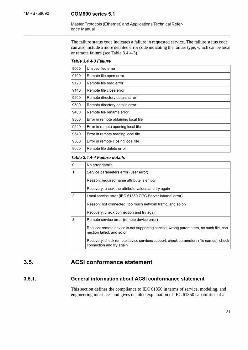
The failure status code indicates a failure in requested service. The failure status codecan also include a more detailed error code indicating the failure type, which can be localor remote failure (see Table 3.4.4-3).
Table 3.4.4-3 FailureUnspecified error9000
Remote file open error9100
Remote file read error9120
Remote file close error9140
Remote directory details error9200
Remote directory details error9300
Remote file rename error9400
Error in remote obtaining local file9500
Error in remote opening local file9520
Error in remote reading local file9540
Error in remote closing local file9560
Remote file delete error9600
Table 3.4.4-4 Failure detailsNo error details0
Service parameters error (user error)
Reason: required name attribute is empty
Recovery: check the attribute values and try again
1
Local service error (IEC 61850 OPC Server internal error)
Reason: not connected, too much network traffic, and so on
Recovery: check connection and try again
2
Remote service error (remote device error)
Reason: remote device is not supporting service, wrong parameters, no such file, con-nection failed, and so on
Recovery: check remote device services support, check parameters (file names), checkconnection and try again
3
ACSI conformance statement3.5.
General information about ACSI conformance statement3.5.1.
This section defines the compliance to IEC 61850 in terms of service, modeling, andengineering interfaces and gives detailed explanation of IEC 61850 capabilities of a
81
COM600 series 5.11MRS758690
Master Protocols (Ethernet) and Applications Technical Refer-ence Manual

product. ACSI conformance statement describes the abstract services interfaces, whichare normally mapped to certain SCSM (Specific communication service mapping) andtherefore indirectly stated in PICS (Protocol Implementation Conformance Statement).
ACSI basic conformance statement3.5.2.
Table 3.5.2-1 ACSI basic conformance statementValue/ Com-ments
Server/ Pub-lisher
Client/ Sub-scriber
Client-Server roles
a-Server side (of TWO-PARTY-APPLICATION-ASSOCIATION)
B11
Supported-aClient side of (TWO-PARTY-APPLICATION-ASSOCIATION)
B12
SCSMs supported
SupportedSCSM: IEC 6185-8-1 usedB21
Not supportedSCSM: IEC 6185-9-1 usedB22
Not supportedSCSM: IEC 6185-9-2 usedB23
SCSM: otherB24
Generic substation eventmodel (GSE)
O-Publisher sideB31
Supported-OSubscriber sideB32
Transmission of sampledvalue model (SVC)
O-Publisher sideB41
Not supported-OSubscriber sideB42
a. Will be M if support for LOGICAL DEVICE model has been declared.
ACSI models conformance statement3.5.3.
Table 3.5.3-1 ACSI models conformance statementValue/ Com-ments
Server/ Pub-lisher
Client/ Sub-scriber
Server (If B1 side suppor-ted)
SupportedaaLogical deviceM1
82
1MRS758690COM600 series 5.1
Master Protocols (Ethernet) and Applications Technical Refer-ence Manual

Value/ Com-ments
Server/ Pub-lisher
Client/ Sub-scriber
SupportedbbLogical nodeM2
SupportedccDataM3
SupportedddData setM4
SupportedOOSubstitutionM5
Supported(through Transpar-ent XSAT)
OOSetting group controlM6
Reporting
SupportedOOBuffered report controlM7
sequence-numberM7-1
report-time-stampM7-2
reason-for-inclusionM7-3
data-set-nameM7-4
data-referenceM7-5
buffer-overflowM7-6
EntryIDM7-7
BufTimM7-8
IntgPdM7-9
GIM7-10
SupportedMMUnbuffered report controlM8
sequence-numberM8-1
report-time-stampM8-2
reason-for-inclusionM8-3
data-set-nameM8-4
data-referenceM8-5
BufTimM8-6
IntgPdM8-7
Not supportedOOLogging
Supported(through Transpar-ent XSAT)
OOLog controlM9
IntgPdM9-1
Not supportedOOLogM10
SupportedMMControlM11
83
COM600 series 5.11MRS758690
Master Protocols (Ethernet) and Applications Technical Refer-ence Manual

Value/ Com-ments
Server/ Pub-lisher
Client/ Sub-scriber
GSE (if B31/B32 is suppor-ted)
SupportedOOGOOSE
EntryIDM12-1
DataRefIncM12-2
Not supportedOOGSSEM13
SVC (if 41/42 is suppor-ted)
Not supportedOOMulticast SVCM14
Not supportedOOUnicast SVCM15
Supported (Timesource withrequired accuracywill be available)
MMTimeM16
SupportedOOFile transferM17
a. Will be M if support for LOGICAL NODE model has been declared.
b. Will be M if support for DATA model has been declared.
c. Will be M if support for DATA SET, Substitution, Report, Log Control, or Timemodel has been declared.
d. Will be M if support for Report, GSE, or SMV models has been declared.
ACSI service conformance statement3.5.4.
The ACSI service conformance statement is defined in Table 3.5.4-1 (depending on thestatements in Table 3.5.2-1).
Table 3.5.4-1 ACSI service conformance statementCommentsServer (S)Client (C)AA: TP/MC
Server
MTPServerDirectoryS1
Application Associ-ation
SupportedMMAssociateS2
SupportedMMAbortS3
SupportedMMReleaseS4
Logical device
84
1MRS758690COM600 series 5.1
Master Protocols (Ethernet) and Applications Technical Refer-ence Manual

CommentsServer (S)Client (C)AA: TP/MC
SupportedMMTPLogicalDeviceDirectoryS5
Logical node
SupportedMMTPLogicalNodeDirectoryS6
Not supportedMOTPGetAllDataValuesS7
Data
SupportedMMTPGetDataValuesS8
SupportedOOTPSetDataValuesS9
SupportedMOTPGetDataDirectoryS10
SupportedMOvGetDataDefinitionS11
Data set
SupportedMOTPGetDataSetValuesS12
Not supportedOOTPSetDataSetValuesS13
SupportedOOTPCreateDataSetS14
Not supportedOOTPDeleteDataSetS15
SupportedOOTPGetDataSetDirectoryS16
Substitution
SupportedMMTPSetDataValuesS17
Setting up control
SupportedOOTPSelectActiveSGS18
SupportedOOTPSelectEditSGS19
Supported(throughTransparentXSAT)
OOTPSetSGValuesS20
SupportedOOTPConfirmEditSGValuesS21
Supported(throughTransparentXSAT)
OOTPGetSGValuesS22
SupportedOOTPGetSGCBValuesS23
Reporting
Buffered report controlblock (BRCB)
SupportedaaTPReportS24
data-change (dchg)S24-1
qchg-change (qchg)S24-2
data-update (dupd)S24-3
85
COM600 series 5.11MRS758690
Master Protocols (Ethernet) and Applications Technical Refer-ence Manual

CommentsServer (S)Client (C)AA: TP/MC
SupportedaaTPGetBRCBValuesS25
SupportedaaTPSetBRCBValuesS26
Unbuffered report con-trol block (URBC)
SupportedaaTPReportS27
data-change (dchg)S27-1
qchg-change (qchg)S27-2
data-update (dupd)S27-3
SupportedaaTPGetURCBValuesS28
SupportedaaTPSetURCBValuesS29
Logging
Log control block
Supported(throughTransparentXSAT)
MTPGetLCBValuesS30
Supported(throughTransparentXSAT)
MTPSetLCBValuesS31
Log
Not supportedMbTPQueryLogByTimeS32
Not supportedMbTPQueryLogByEntryS33
Supported(throughTransparentXSAT)
MTPGetLogStatusValuesS34
Generic substationevent model (GSE)
GOOSE-CONTROL-BLOCK
Not supportedccMCSendGOOSEMessageS35
Not supporteddOTPGetReferenceS36
Not supporteddOTPGetGOOSEElement-Number
S37
SupportedOOTPGetGoCBValuesS38
SupportedOOTPSetGoCBValuesS39
Not supportedccMCSendGSSEMessageS40
Not supporteddOTPGetReferenceS41
86
1MRS758690COM600 series 5.1
Master Protocols (Ethernet) and Applications Technical Refer-ence Manual

CommentsServer (S)Client (C)AA: TP/MC
Not supporteddOTPGetGSSEElementNum-ber
S42
Supported(throughTransparentXSAT)
OOTPGetGsCBValuesS43
Supported(throughTransparentXSAT)
OOTPSetGsCBValuesS44
Transmission ofsampled value model(SVC)
Multicast SVC
Not supportedeeMCSendMSVMessageS45
Supported(throughTransparentXSAT)
OOTPGetMSVCBValuesS46
Supported(throughTransparentXSAT)
OOTPSetMSVCBValuesS47
Unicast SVC
Not supportedeeTPSendUSVMessageS48
Supported(throughTransparentXSAT)
OOTPGetUSVCBValuesS49
Supported(throughTransparentXSAT)
OOTPSetUSVCBValuesS50
Control
SupportedMMSelectS51
SupportedMMTPSelectWithValueS52
SupportedMOTPCancelS53
SupportedMMTPOperateS54
SupportedMMTPCommand-TerminationS55
Not supportedOOTPTimeActivated-OperateS56
File transfer
SupportedMOTPGetFileS57
87
COM600 series 5.11MRS758690
Master Protocols (Ethernet) and Applications Technical Refer-ence Manual

CommentsServer (S)Client (C)AA: TP/MC
SupportedOOTPSetFileS58
SupportedOOTPDeleteFileS59
SupportedMOTPGetFileAttributeValuesS60
Time
(nearest negat-ive power of 2in seconds)
Time resolution ofinternal clock
T1
T0Time accuracy ofinternal clock
T2
T1
T2
T3
T4
T5
(nearest negat-ive power of 2in seconds)
supported TimeStampresolution
T3
a. Will declare support for at least one (BRCB or URCB).
b. Will declare support for at least one (QueryLogByTime or QueryLogByEntry).
c. Will declare support for at least one (SendGOOSEMessage or SendGSSEMessage).
d. Will declare support if TP association is available.
e. Will declare support for at least one (SendMSVMessage or SendUSVMessage).
88
1MRS758690COM600 series 5.1
Master Protocols (Ethernet) and Applications Technical Refer-ence Manual

IEC 104 OPC server4.
About this section4.1.
This section provides reference information about the following issues:• IEC 61850 data modeling• Attributes• Status codes
IEC 61850 data modeling4.2.
General information about IEC 61850 data modeling4.2.1.
The relationship between the IEC 61850 data modeling and IEC104 OPC Server isdescribed in this section.
For each data class, there is a table giving a detailed description about the relation betweenthe IEC104 data and IEC 61850 data object attributes and services. The tables alsodescribe how the data is presented on the OPC Server name space.
The columns in the tables have the following content types:• Name specifies the OPC item name of the attribute/service.• Type specifies the IEC 61850 type of the attribute.• Value/ Value range specifies the allowed values and ranges of the attribute/service.• Mandatory/Optional specifies whether the attribute is considered as mandatory or
optional according to the IEC 61850 standard.• IEC104 information element specifies the IEC104 information element related to
the attribute/service.• OPC data types specify the OPC data type used for the OPC item.
Single point status (SPS)4.2.2.
OPC data typesProtocol informa-tion element
Mandat-ory/Optional
Value/Value rangeTypeName
VT_BOOLSPI(0=ON, 1=OFF)MTRUE | FALSEBOOLEANstVal
VT_I4BL, SB, NT, IVMQualityq
VT_DATECP24Time2a
CP56Time2a
MTimeStampt
89
COM600 series 5.11MRS758690
Master Protocols (Ethernet) and Applications Technical Refer-ence Manual
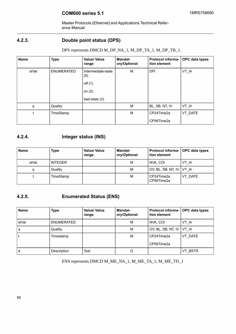
Double point status (DPS)4.2.3.
DPS represents DMCD M_DP_NA_1, M_DP_TA_1, M_DP_TB_1.
OPC data typesProtocol informa-tion element
Mandat-ory/Optional
Value/ Valuerange
TypeName
VT_I4DPIMIntermediate-state(0)
off (1)
on (2)
bad-state (3)
ENUMERATEDstVal
VT_I4BL, SB, NT, IVMQualityq
VT_DATECP24Time2a
CP56Time2a
MTimeStampt
Integer status (INS)4.2.4.
OPC data typesProtocol informa-tion element
Mandat-ory/Optional
Value/ Valuerange
TypeName
VT_I4NVA, COIMINTEGERstVal
VT_I4OV, BL, SB, NT, IVMQualityq
VT_DATECP24Time2aCP56Time2a
MTimeStampt
Enumerated Status (ENS)4.2.5.
OPC data typesProtocol informa-tion element
Mandat-ory/Optional
Value/ Valuerange
TypeName
VT_I4NVA, COIMENUMERATEDstVal
VT_I4OV, BL, SB, NT, IVMQualityq
VT_DATECP24Time2a
CP56Time2a
MTimestampt
VT_BSTROTextDescriptiond
ENS represents DMCD M_ME_NA_1, M_ME_TA_1, M_ME_TD_1
90
1MRS758690COM600 series 5.1
Master Protocols (Ethernet) and Applications Technical Refer-ence Manual

Protection activation information (ACT)4.2.6.
ACT represents DMCD M_SP_NA_1, M_SP_TA_1, M_SP_TB_1, M_DP_NA_1,M_DP_TA_1, M_DP_TB_1.
OPC data typesProtocol informa-tion element
Mandat-ory/Optional
Value/ Valuerange
TypeName
VT_BOOLSPIMBOOLEANgeneral
VT_BOOLSPIOBOOLEANphsA
VT_BOOLSPIOBOOLEANphsB
VT_BOOLSPIOBOOLEANphsC
VT_BOOLSPIOBOOLEANneut
VT_I4EI, BL, SB, NT, IVMQualityq
Directional protection activation information (ACD)4.2.7.
ACD represents M_SP_NA_1, M_SP_TA_1, M_SP_TB_1, M_DP_NA_1, M_DP_TA_1,M_DP_TB_1.
OPC data typesProtocol informa-tion element
Mandat-ory/Optional
Value/ Valuerange
TypeName
VT_BOOLSPIMBOOLEANgeneral
VT_I4Munknown
forward
backward
ENUMERATEDdirGeneral
VT_BOOLSPIOBOOLEANphsA
VT_I4Ounknown
forward
backward
ENUMERATEDdirPhsA
VT_BOOLSPIOBOOLEANphsB
VT_I4Ounknown
forward
backward
ENUMERATEDdirPhsB
VT_BOOLSPIOBOOLEANphsC
VT_I4Ounknown
forward
backward
ENUMERATEDdirPhsC
VT_BOOLSPIOBOOLEANneut
91
COM600 series 5.11MRS758690
Master Protocols (Ethernet) and Applications Technical Refer-ence Manual
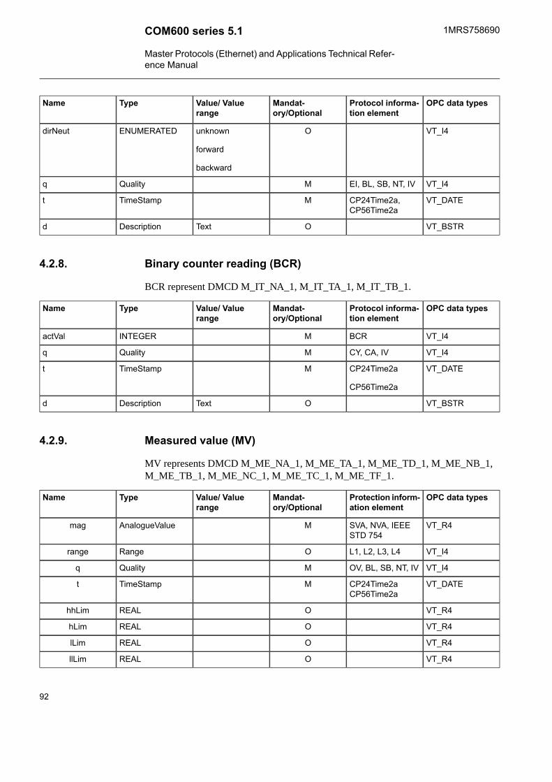
OPC data typesProtocol informa-tion element
Mandat-ory/Optional
Value/ Valuerange
TypeName
VT_I4Ounknown
forward
backward
ENUMERATEDdirNeut
VT_I4EI, BL, SB, NT, IVMQualityq
VT_DATECP24Time2a,CP56Time2a
MTimeStampt
VT_BSTROTextDescriptiond
Binary counter reading (BCR)4.2.8.
BCR represent DMCD M_IT_NA_1, M_IT_TA_1, M_IT_TB_1.
OPC data typesProtocol informa-tion element
Mandat-ory/Optional
Value/ Valuerange
TypeName
VT_I4BCRMINTEGERactVal
VT_I4CY, CA, IVMQualityq
VT_DATECP24Time2a
CP56Time2a
MTimeStampt
VT_BSTROTextDescriptiond
Measured value (MV)4.2.9.
MV represents DMCD M_ME_NA_1, M_ME_TA_1, M_ME_TD_1, M_ME_NB_1,M_ME_TB_1, M_ME_NC_1, M_ME_TC_1, M_ME_TF_1.
OPC data typesProtection inform-ation element
Mandat-ory/Optional
Value/ Valuerange
TypeName
VT_R4SVA, NVA, IEEESTD 754
MAnalogueValuemag
VT_I4L1, L2, L3, L4ORangerange
VT_I4OV, BL, SB, NT, IVMQualityq
VT_DATECP24Time2aCP56Time2a
MTimeStampt
VT_R4OREALhhLim
VT_R4OREALhLim
VT_R4OREALlLim
VT_R4OREALllLim
92
1MRS758690COM600 series 5.1
Master Protocols (Ethernet) and Applications Technical Refer-ence Manual

OPC data typesProtection inform-ation element
Mandat-ory/Optional
Value/ Valuerange
TypeName
VT_R4OREALmin
VT_R4OREALmax
VT I4ConfigOSiUnitunit
VT_BSTROTextDescriptiond
Complex measured value (CMV)4.2.10.
CMV is configured in the same way as MV. The only difference is that instead of a‘mag’ item, there is a ‘cVal’ node containing a ‘mag’ item.
WYE4.2.11.
WYE represent DMCD M_ME_NA_1, M_ME_TA_1, M_ME_TD_1, M_ME_NB_1,M_ME_TB_1, M_ME_NC_1, M_ME_TC_1, M_ME_TF_1.
OPC data typesProtocol informa-tion element
Mandat-ory/Optional
Value/ Valuerange
TypeName
VT_R4
VT_I4
VT_DATE
SVA, NVA
OV, BL, SB, NT, IV
CP24Time2A
M
M
M
AnalogueValue
Quality
TimeStamp
phsA.cVal.mag
phsA.q
phsA.t
VT_R4
VT_I4
VT_DATE
SVA, NVA
OV, BL, SB, NT, IV
CP24Time2A
O
O
O
AnalogueValue
Quality
TimeStamp
phsB.cVal.mag
phsB.q
phsB.t
VT_R4
VT_I4
VT_DATE
SVA, NVA
OV, BL, SB, NT, IV
CP24Time2A
O
O
O
AnalogueValue
Quality
TimeStamp
phsC.cVal.mag
phsC.q
phsC.t
VT_R4
VT_I4
VT_DATE
SVA, NVA
OV, BL, SB, NT, IV
CP24Time2A
O
O
O
AnalogueValue
Quality
TimeStamp
neut.cVal.mag
neut.q
neut.t
93
COM600 series 5.11MRS758690
Master Protocols (Ethernet) and Applications Technical Refer-ence Manual

Delta (DEL)4.2.12.
DEL represents DMCD M_ME_NA_1, M_ME_TA_1, M_ME_TD_1, M_ME_NB_1,M_ME_TB_1, M_ME_NC_1, M_ME_TC_1, M_ME_TF_1.
OPC data typesProtocol informa-tion element
Mandat-ory/Optional
Value/ Valuerange
TypeName
VT_R4
VT_I4
VT_DATE
SVA, NVA
OV, BL, SB, NT, IV
CP24Time2A
M
M
M
AnalogueValue
Quality
TimeStamp
phsAB. cVal.mag t
phsAB.q
phsAB.t
VT_R4
VT_I4
VT_DATE
SVA, NVA
OV, BL, SB, NT, IV
CP24Time2A
M
M
M
AnalogueValue
Quality
TimeStamp
phsBC.cVal.mag q
phsBC.q
phsBC.t
VT_R4
VT_I4
VT_DATE
SVA, NVA
OV, BL, SB, NT, IV
CP24Time2A
M
M
M
AnalogueValue
Quality
TimeStamp
phsCA.cVal.mag q
phsCA.q
phsCA.t
Controllable single point (SPC)4.2.13.
SPC represents DMCD C_SC_NA_1, C_DC_NA_1, M_SP_NA_1, M_SP_TA_1,M_SP_TB_1, M_DP_NA_1, M_DP_TA_1, M_DP_TB_1.
OPC data typesProtocol informa-tion element
Mandat-ory/Optional
Value/ Valuerange
TypeName
VT_BOOLSCOMSPIctlVal
VT_BOOLSPIMFALSE | TRUEstVal
VT_I4BL, SB, NT, IVMQualityq
VT_DATECP24Time2AMTimeStampt
VT_BSTROTextDescriptiond
Controllable double point (DPC)4.2.14.
DPC represents DMCD C_SC_NA_1, C_DC_NA_1, M_SP_NA_1, M_SP_TA_1,M_SP_TB_1, M_DP_NA_1, M_DP_TA_1, M_DP_TB_1.
OPC data typesProtocol informa-tion element
Mandat-ory/Optional
Value/ Valuerange
TypeName
VT_BOOLSCOOFALSE | TRUESPIctlOperOn
VT_BOOLSCOOFALSE | TRUEctlOperOff
94
1MRS758690COM600 series 5.1
Master Protocols (Ethernet) and Applications Technical Refer-ence Manual

OPC data typesProtocol informa-tion element
Mandat-ory/Optional
Value/ Valuerange
TypeName
VT_BOOLSCOOFALSE | TRUEctlSelOn
VT_BOOLSCOOFALSE | TRUEctlSelOff
VT_I4DPIMintermediate-state(0)
off (1)
on (2)
bad-state (3)
ENUMERATEDstVal
VT_I4BL, SB, NT, IVMQualityq
VT_DATECP24TIME2AMTimeStampt
VT_BOOLSCOOFALSE | TRUEBOOLEANctlCan
VT_BOOLSPIOFALSE | TRUEBOOLEANstSeld
Controllable integer status (INC)4.2.15.
OPC data typesProtocol informa-tion element
Mandat-ory/Optional
Value/ Valuerange
TypeName
VT_I4NVAMINTEGERctlVal
VT_I4VAI32MINTEGERstVal
VT_I4BL, SB, NT, IVMQualityq
VT_DATECP24TIME2AMTimeStampt
VT_BSTROTextDescriptiond
Controllable Enumerated Status (ENC)4.2.16.
ENC represents DMCD M_ME_NA_1, M_ME_TA_1, M_ME_TD_1, M_ME_NB_1,M_ME_TB_1, C_SE_NA, C_SE_NB_1.
OPC data typesProtocol informa-tion element
Mandat-ory/Optional
Value/ Valuerange
TypeName
VT_I4NVAMENUMERATEDctlVal
VT_I4VAI32MENUMERATEDstVal
VT_I4BT, SB, NT, IVMQualityq
VT_DATECP24Time2aMTimestampt
VT_BSTROTextDescriptiond
95
COM600 series 5.11MRS758690
Master Protocols (Ethernet) and Applications Technical Refer-ence Manual

Binary controlled step position information (BSC)4.2.17.
BSC represents DMCD M_ST_NA_1, M_ST_TA_1, M_ST_TB_1, M_RC_NA_1.
OPC data typesProtocol informa-tion element
Mandat-ory/Optional
Value/ Valuerange
TypeName
VT_I1RCOMstop (0)
lower (1)
higher (2)
reserved (3)
ENUMERATEDctlVal
VT_I4VTIMValWithTransvalWTr
VT_I4BL, SB, NT, IVMQualityq
VT_DATECP24Time2aMTimeStampt
VT_BSTROTextDescriptiond
Integer controlled step position information (ISC)4.2.18.
ISC represents C_SE_NA_1, C_SE_NB_1, M_ST_NA_1, M_ST_TA_1, M_ST_TB_1.
OPC data typesProtocol informa-tion element
Mandat-ory/Optional
Value/ Valuerange
TypeName
NVAM-64 ... 63INTEGERctlVal
VT_I4VTIMValWithTransvalWTr
V_I4BL, SB, NT, IVMQualityq
V_DATECP24TIME2AMTimeStampt
VT_BSTROTextDescriptiond
Analogue set point (APC)4.2.19.
APC represents DMCD C_SE_NC_1.
OPC data typesProtocol informa-tion element
Mandat-ory/Optional
Value/ Valuerange
TypeName
VT_R4MAnalogueValuectlVal
96
1MRS758690COM600 series 5.1
Master Protocols (Ethernet) and Applications Technical Refer-ence Manual
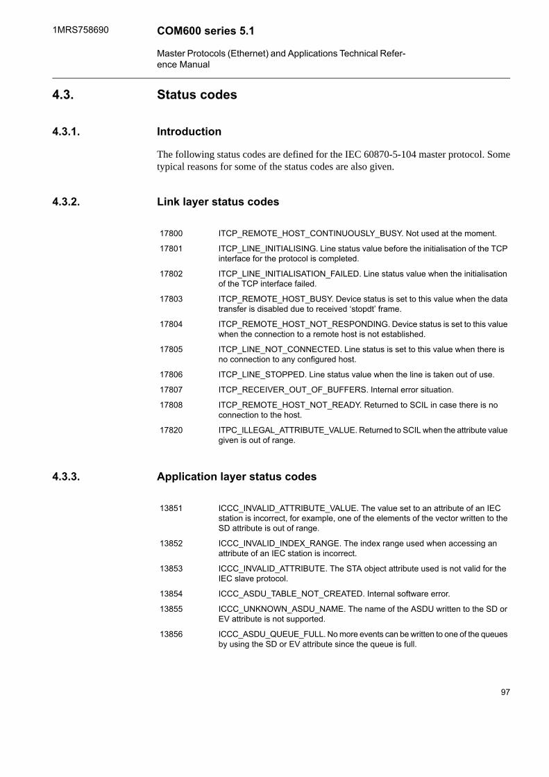
Status codes4.3.
Introduction4.3.1.
The following status codes are defined for the IEC 60870-5-104 master protocol. Sometypical reasons for some of the status codes are also given.
Link layer status codes4.3.2.
ITCP_REMOTE_HOST_CONTINUOUSLY_BUSY. Not used at the moment.17800
ITCP_LINE_INITIALISING. Line status value before the initialisation of the TCPinterface for the protocol is completed.
17801
ITCP_LINE_INITIALISATION_FAILED. Line status value when the initialisationof the TCP interface failed.
17802
ITCP_REMOTE_HOST_BUSY. Device status is set to this value when the datatransfer is disabled due to received ‘stopdt’ frame.
17803
ITCP_REMOTE_HOST_NOT_RESPONDING. Device status is set to this valuewhen the connection to a remote host is not established.
17804
ITCP_LINE_NOT_CONNECTED. Line status is set to this value when there isno connection to any configured host.
17805
ITCP_LINE_STOPPED. Line status value when the line is taken out of use.17806
ITCP_RECEIVER_OUT_OF_BUFFERS. Internal error situation.17807
ITCP_REMOTE_HOST_NOT_READY. Returned to SCIL in case there is noconnection to the host.
17808
ITPC_ILLEGAL_ATTRIBUTE_VALUE. Returned to SCIL when the attribute valuegiven is out of range.
17820
Application layer status codes4.3.3.
ICCC_INVALID_ATTRIBUTE_VALUE. The value set to an attribute of an IECstation is incorrect, for example, one of the elements of the vector written to theSD attribute is out of range.
13851
ICCC_INVALID_INDEX_RANGE. The index range used when accessing anattribute of an IEC station is incorrect.
13852
ICCC_INVALID_ATTRIBUTE. The STA object attribute used is not valid for theIEC slave protocol.
13853
ICCC_ASDU_TABLE_NOT_CREATED. Internal software error.13854
ICCC_UNKNOWN_ASDU_NAME. The name of the ASDU written to the SD orEV attribute is not supported.
13855
ICCC_ASDU_QUEUE_FULL. No more events can be written to one of the queuesby using the SD or EV attribute since the queue is full.
13856
97
COM600 series 5.11MRS758690
Master Protocols (Ethernet) and Applications Technical Refer-ence Manual

ICCC_MESSAGE_BUFFER_FULL. Internal software error. The value of the MLattribute may be too small.
13857
ICCC_MESSAGE_FILLING_ERROR. Internal software error. The value of theML attribute may be too small.
13858
ICCC_UNKNOWN_ASDU. The number of the ASDU written to the SD or EVattribute is not supported.
13859
ICCC_NO_ACTIVE_COMMAND. There is no preceding command with the givenaddress when confirming a command by using the CF attribute. Either the addressis incorrect or the command has not been received.
13860
ICCC_INVALID_QUEUE_NUMBER. The index of the SD or EV attribute isincorrect.
13861
ICCC_SC_DATA_OVERFLOW. Internal software error.13862
ICCC_DEVICE_SUSPENDED. The IEC station is in the suspended state. Thereason for this could be that the link is not properly established (for example,incorrect cable wiring) or the master does not respond.
13863
ICCC_MESSAGE_SENDING_ERROR. Internal software error. This may be theresult of a problem in wiring or hardware.
13864
ICCC_REMOTE_DEVICE_REPLIES_WITH_NACK. The master did not acceptthe message but responded with a negative acknowledgment instead. Not usedin the unbalanced mode.
13865
ICCC_LINK_NOT_READY. A message is sent to a line with a non-establishedcommunication.
13866
ICCC_OUT_OF_BUFFERS. Internal software error. Operation could not becompleted since the buffer pool has run out of buffers.
13868
ICCC_DONT_REPLY. Internal software error.13869
ICCC_DEVICE_STOPPED. The station has been set out of use by using the IUattribute.
13872
ICCC_NO_ADDRESS_IN_ACP. Internal software error.13873
ICCC_UNEXPECTED_TYPE_IN_ACP. Internal software error.13875
Attributes4.4.
Server attributes4.4.1.
Table 4.4.1-1 IEC 104 OPC Server attributesDescriptionValue or Value range/ DefaultProperty / Para-
meter
The version information of the ProtocolStack.
Value: Version informationProtocol Stack Ver-sion
98
1MRS758690COM600 series 5.1
Master Protocols (Ethernet) and Applications Technical Refer-ence Manual

Channel attributes4.4.2.
Table 4.4.2-1 Channel attributesDescriptionValue or Value range/ DefaultProperty / Para-
meter
Basic
The state of the channel - whether it is inuse or not. When a channel is not in use,no data can be transmitted on it, and nodata is received from it. The channelattributes can be read as usual. Generally,a channel must be taken out of use bysetting this attribute to 0 before the chan-nel attributes can be written.
When a channel is stopped by setting theIn use attribute to 0, all data transmissionon the channel ceases. However, beforethat, the protocol stack executes to theend all on-going data transactions. Forexample, the of the station in turn is com-pleted.
0 = Not in use, the channelcommunication is stopped.
1 = In use.
In use
Diagnostic Coun-ters
The number of transmitted data messages.Transmitted tele-grams
The number of failed transmissions.Failed transmissions
The number of transmitted commands.Timeout errors
The number of transmitted informationmessages.
Transmitted I formatmessages
The number of transmitted supervisorymessages.
Transmitted Sformat messages
The number of transmitted unnumberedmessages.
Transmitted Uformat messages
The number of received information mes-sages.
Received I formatmessages
The number of received supervisory mes-sages.
Received S formatmessages
The number of received unnumberedmessages.
Received U formatmessages
The number of received messages.Received messages
The count of TCP connect request.TCP Connect count
The count of accepted TCP connectrequest.
TCP Accept count
The count of closed TCP connection.TCP Close count
99
COM600 series 5.11MRS758690
Master Protocols (Ethernet) and Applications Technical Refer-ence Manual

DescriptionValue or Value range/ DefaultProperty / Para-meter
The number of times duplicates and losseshas occurred.
Duplicates andlosses
The number of times there as been a buf-fer overflow.
Buffer overflowerrors
Device attributes4.4.3.
Table 4.4.3-1 Device attributesDescriptionValue or Value range/ DefaultProperty / Para-
meter
Basic
The operational status of the device - inuse or out of use. Taking the device outof use with this attribute stops all datacommunication with the device. All opera-tions that would result in a data exchangeare disabled. The device itself is notaffected by the attribute, only the protocolstack’s image of the device. Setting In useto 1 is allowed only if the device addressis legal.
0 = Out of use
1 = In use
Default: 1
In use
This attribute enables or disables dia-gnostic events.
True = Diagnostic eventsenabled
False = Diagnostic events dis-abled
Diagnostic EventsEnabled
Status Information
Indicates the status of the device connec-tion.
True = Device connection OK
False = Device connectionsuspended.
Connection Status
100
1MRS758690COM600 series 5.1
Master Protocols (Ethernet) and Applications Technical Refer-ence Manual

DescriptionValue or Value range/ DefaultProperty / Para-meter
Indicates the detailed information aboutthe station device status. Setting DetailedStatus of a device to 1 makes the protocolstack to re-transmit the last system mes-sage caused by the device. Possible‘Stopped’ and ‘Suspended’ messagescause old marking of OPC items.
When written:
1 = Re-transmit system mes-sage
When read:
A status code, e.g.
0 = OK (communication worksproperly)
13863 = Device suspended.
For more information, see4.3.2, Link layer status codesand 4.3.3, Application layerstatus codes.
Detailed Status
Diagnostic coun-ters
Indicates the number of times the connec-tion has been suspended.
Suspensions
The number of transmitted data messages.Transmitted DataMessages
The number of transmitted commandmessages.
Transmitted Com-mand Messages
The number of transmitted confirmationmessages.
Transmitted Confirm-ation Messages
The number of received data messages.Received DataMessages
The number of received command mes-sages.
Received CommandMessages
The number of received confirmationmessages.
Received Confirma-tion Messages
The number of unknown messagesreceived.
Received UnknownMessages
101
COM600 series 5.11MRS758690
Master Protocols (Ethernet) and Applications Technical Refer-ence Manual

DNP3 LAN/WAN OPC server5.
About this section5.1.
This section provides reference information about the following issues:• IEC 61850 data modeling• Attributes• Status codes
IEC 61850 data modeling5.2.
General information about IEC 61850 data modeling5.2.1.
The relationship between the IEC 61850 data modeling and DNP LAN Slave OPC Clientis described in this section.
For each data class, there is a table giving a detailed description about the relation betweenthe DNP data and IEC 61850 data object attributes and services. The tables also describehow the data is presented on the OPC Server name space.
The columns in the tables have the following content types:• Name specifies the OPC item name of the attribute/service.• Type specifies the IEC 61850 type of the attribute.• Value/ Value range specifies the allowed values and ranges of the attribute/service.• Mandatory/Optional specifies whether the attribute is considered as mandatory or
optional according to the IEC 61850 standard.• DNP information element specifies the DNP information element related to the
attribute/service.• OPC data types specify the OPC data type used for the OPC item.
Single point status (SPS)5.2.2.
OPC data typesDNP data objectfield
Mandat-ory/Optional
Value/Value rangeTypeName
VT_BOOLMTRUE | FALSEBOOLEANstVal
VT_I4MQualityq
VT_DATEMTimeStampt
102
1MRS758690COM600 series 5.1
Master Protocols (Ethernet) and Applications Technical Refer-ence Manual

Double point status (DPS)5.2.3.
OPC data typesDNP data objectfield
Mandat-ory/Optional
Value/Value rangeTypeName
VT_I4state (0=OFF,1=ON)
MIntermediate-state(0) | off (1) | on (2)| bad-state (3)
CPTstVal
VT_I4DNP statusMQualityq
VT_DATE<server provided ifnone> | Time ofoccurrence | MSEC
MFull TimestampTimeStampt
VT_BSTROTextDescriptiond
Integer status (INS)5.2.4.
OPC data typesDNP data objectfield
Mandat-ory/Optional
Value/Value rangeTypeName
VT_I4Current valueMINTEGERstVal
VT_I4DNP statusMQualityq
VT_DATE<server provided ifnone> | Time ofoccurrence
MTimeStampt
VT_BSTR-OTextDescriptiond
Enumerated Status (ENS)5.2.5.
Table 5.2.5-1 Enumerated Status (ENS)OPC data typesProtocol informa-
tion elementMandat-ory/Optional
Value/Value rangeTypeName
VT_I4Current valueMENUMERATEDstVal
VT_I4DNP statusMQualityq
VT_DATE<server provided ifnone> | Time ofoccurrence
MTimestampt
VT_BSTROTextDescriptiond
103
COM600 series 5.11MRS758690
Master Protocols (Ethernet) and Applications Technical Refer-ence Manual

Protection activation information (ACT)5.2.6.
OPC data typesDNP data objectfield
Mandat-ory/Optional
Value/Value rangeTypeName
VT_BOOLstate (0=OFF,1=ON)
MBOOLEANgeneral
VT_BOOLstate (0=OFF,1=ON)
OBOOLEANphsA
VT_BOOLstate (0=OFF,1=ON)
OBOOLEANphsB
VT_BOOLstate (0=OFF,1=ON)
OBOOLEANphsC
VT_BOOLstate (0=OFF,1=ON)
OBOOLEANneut
VT_14DNP statusMQualityq
VT_Date<server provided ifnone> | Time ofoccurrence
MTimeStampt
VT_Date-OTextDescriptiond
Directional protection activation information (ACD)5.2.7.
OPC data typesDNP data objectfield
Mandat-ory/Optional
Value/Value rangeTypeName
VT_BOOLstate (0=OFF,1=ON)
MBOOLEANgeneral
VT_BOOLstate (0=OFF,1=ON)
OBOOLEANphsA
VT_BOOLstate (0=OFF,1=ON)
OBOOLEANphsB
VT_BOOLstate (0=OFF,1=ON)
OBOOLEANphsC
VT_BOOLstate (0=OFF,1=ON)
OBOOLEANneut
VT_14DNP statusMQualityq
VT_DATE<server provided ifnone> | Time ofoccurrence| MSEC
MTimeStampt
VT_BSTR-OTextDescriptiond
104
1MRS758690COM600 series 5.1
Master Protocols (Ethernet) and Applications Technical Refer-ence Manual

Binary counter reading (BCR)5.2.8.
OPC data typesDNP data objectfield
Mandat-ory/Optional
Value/Value rangeTypeName
VT_I4Value | Frozenvalue | Currentvalue
MINTEGERactVal
VT_14ConfigOIntegersiUnit
VT_14ConfigOIntegermultiplier
VT_BSTRConfigOIntegerunit
VT_I4DNP statusMQualityq
VT_DATE<server provided ifnone> | Time ofoccurrence | MSCE
MTimeStampt
Device name plate (DPL)5.2.9.
OPC data typesDNP data objectfield
Mandat-ory/Optional
Value/Value rangeTypeName
VT_BSTR-MVisibleStringvendor
VT_BSTR-OVisibleStringhwRevision
VT_BSTR-OVisibleStringswRevision
VT_BSTR-OVisibleStringserNum
VT_BSTR-OVisibleStringlocation
Logical node name plate (LPL)5.2.10.
OPC data typesDNP informationelement
Mandat-ory/Optional
Value/Value rangeTypeName
VT_BSTRSeparate signalMVisibleStringvendor
VT_BSTRSeparate signalMVisibleStringswRev
VT_BSTRSeparate signalMVisibleStringd
105
COM600 series 5.11MRS758690
Master Protocols (Ethernet) and Applications Technical Refer-ence Manual

Measured value (MV)5.2.11.
Table 5.2.11-1 Measured value (MV) informationOPC data typesDNP data object
fieldMandat-ory/Optional
Value/Value rangeTypeName
VT_R4Current valueMAnalogueValuemag
VT_I4DNP statusMQualityq
VT_DATEserver provided ifnone
| Time of occur-rence
| MSEC
MTimeStampt
VT_BSTR-OTextDescriptiond
VT_R4-OREALhhLim
VT_R4-OREALllLim
VT_R4-OREALlLim
VT_R4-OREALmin
VT_R4-OREALmax
VT_I4ConfigOIntegersiUnit
VT_I4ConfigOIntegermultiplier
VT_BSTRConfigOStringunit
VT_I4ConfigOIntegernumOfDec
VT_I4-ORangerange
Complex measured value (CMV)5.2.12.
CMV is configured in the same way as MV.
106
1MRS758690COM600 series 5.1
Master Protocols (Ethernet) and Applications Technical Refer-ence Manual

WYE5.2.13.
OPC data typesDNP informationelement
Mandat-ory/Optional
Value/Value rangeTypeName
VT_R4
VT_I4
VT_DATE
VT_I4
VT_R4
VT_R4
VT_R4
VT_R4
VT_R4
VT_R4
VT_I4
VT_I4
VT_BSTR
Phase A CurrentValue
on-line, com lost
–
Separate Signal
Separate signal
Separate signal
Separate signal
Separate signal
Separate signal
Separate signal
Separate signal
Separate signal
Separate signal
M
M
M
O
O
O
O
O
O
O
O
O
O
AnalogueValue
Quality
TimeStamp
Range
REAL
REAL
REAL
REAL
REAL
REAL
ENUMRATED
ENUMERATED
String
phsA. mag
phsA.q
phsA.t
phsA.range
phsA.hhLim
phsA.hLim
phsA.lLim
phsA.llLim
phsA.min
phsA.max
phsA.siUnit
phsA.multiplier
phsA.unit
VT_R4
VT_I4
VT_DATE
VT_I4
VT_R4
VT_R4
VT_R4
VT_R4
VT_R4
VT_R4
VT_I4
VT_I4
VT_BSTR
Phase B CurrentValue
on-line, com lost
–
Separate Signal
Separate signal
Separate signal
Separate signal
Separate signal
Separate signal
Separate signal
Separate signal
Separate signal
Separate signal
O
O
O
O
O
O
O
O
O
O
O
O
O
AnalogueValue
Quality
TimeStamp
Range
REAL
REAL
REAL
REAL
REAL
REAL
ENUMERATED
ENUMERATED
String
phsB. mag
phsB.q
phsB.t
phsB.range
phsB.hhLim
phsB.hLim
phsB.lLim
phsB.llLim
phsB.min
phsB.max
phsB.siUnit
phsB.multiplier
phsB.unit
107
COM600 series 5.11MRS758690
Master Protocols (Ethernet) and Applications Technical Refer-ence Manual

OPC data typesDNP informationelement
Mandat-ory/Optional
Value/Value rangeTypeName
VT_R4
VT_I4
VT_DATE
VT_I4
VT_R4
VT_R4
VT_R4
VT_R4
VT_R4
VT_R4
VT_I4
VT_I4
VT_BSTR
Phase C CurrentValue
on-line, com lost
–
Separate Signal
Separate signal
Separate signal
Separate signal
Separate signal
Separate signal
Separate signal
Separate signal
Separate signal
Separate signal
O
O
O
O
O
O
O
O
O
O
O
O
O
AnalogueValue
Quality
TimeStamp
Range
REAL
REAL
REAL
REAL
REAL
REAL
ENUMERATED
ENUMERATED
String
phsC. mag
phsC.q
phsC.t
phsC.range
phsC.hhLim
phsC.hLim
phsC.lLim
phsC.llLim
phsC.min
phsC.max
phsC.siUnit
phsC.multiplier
phsC.unit
VT_R4
VT_I4
VT_DATE
VT_I4
VT_R4
VT_R4
VT_R4
VT_R4
VT_R4
VT_R4
VT_I4
VT_I4
VT_BSTR
Neutral CurrentValue
on-line, com lost
-
Separate Signal
Separate signal
Separate signal
Separate signal
Separate signal
Separate signal
Separate signal
Separate signal
Separate signal
Separate signal
O
O
O
O
O
O
O
O
O
O
O
O
O
AnalogueValue
Quality
TimeStamp
Range
REAL
REAL
REAL
REAL
REAL
REAL
ENUMERATED
ENUMERATED
String
neut. mag
neut.q
neut.t
neut.range
neut.hhLim
neut.hLim
neut.lLim
neut.llLim
neut.min
neut.max
neut.siUnit
neut.multiplier
neut.unit
VT_BSTRSeparate signalODescriptiond
108
1MRS758690COM600 series 5.1
Master Protocols (Ethernet) and Applications Technical Refer-ence Manual
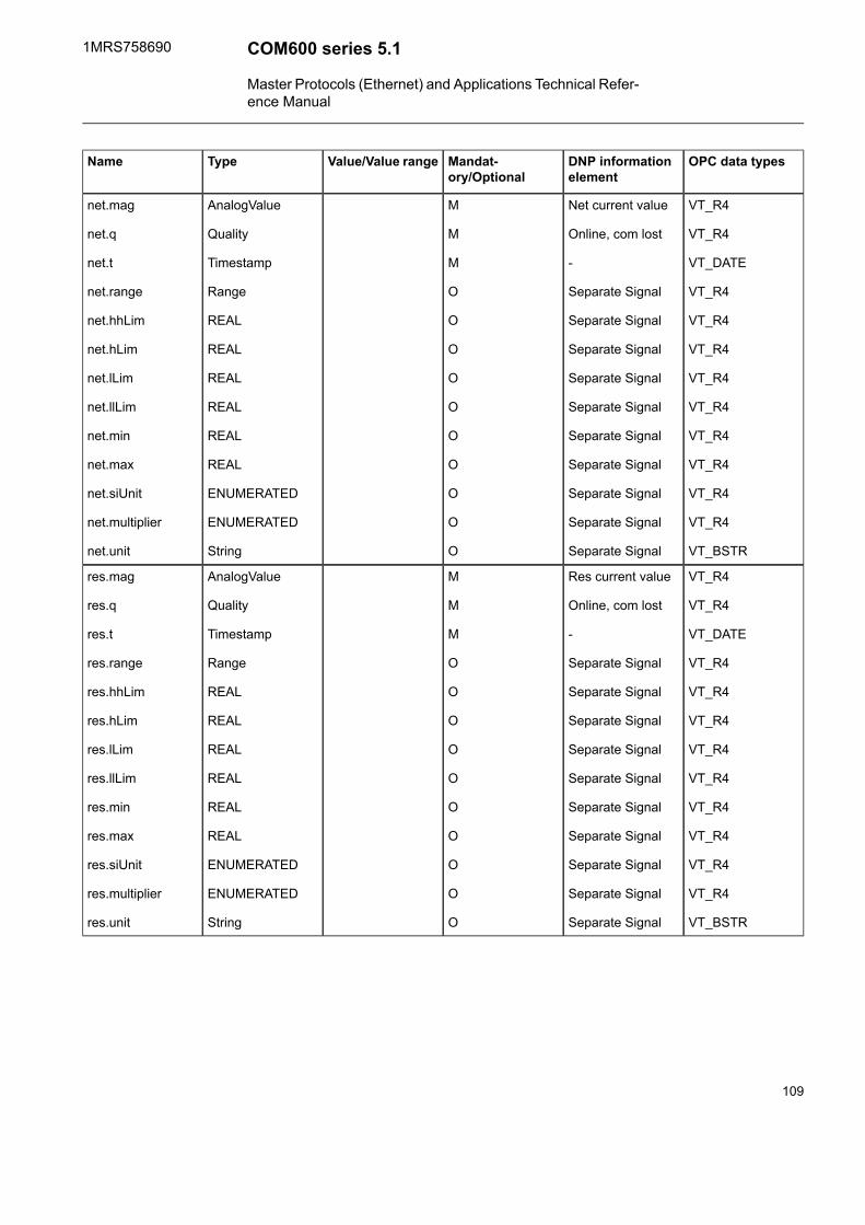
OPC data typesDNP informationelement
Mandat-ory/Optional
Value/Value rangeTypeName
VT_R4
VT_R4
VT_DATE
VT_R4
VT_R4
VT_R4
VT_R4
VT_R4
VT_R4
VT_R4
VT_R4
VT_R4
VT_BSTR
Net current value
Online, com lost
-
Separate Signal
Separate Signal
Separate Signal
Separate Signal
Separate Signal
Separate Signal
Separate Signal
Separate Signal
Separate Signal
Separate Signal
M
M
M
O
O
O
O
O
O
O
O
O
O
AnalogValue
Quality
Timestamp
Range
REAL
REAL
REAL
REAL
REAL
REAL
ENUMERATED
ENUMERATED
String
net.mag
net.q
net.t
net.range
net.hhLim
net.hLim
net.lLim
net.llLim
net.min
net.max
net.siUnit
net.multiplier
net.unit
VT_R4
VT_R4
VT_DATE
VT_R4
VT_R4
VT_R4
VT_R4
VT_R4
VT_R4
VT_R4
VT_R4
VT_R4
VT_BSTR
Res current value
Online, com lost
-
Separate Signal
Separate Signal
Separate Signal
Separate Signal
Separate Signal
Separate Signal
Separate Signal
Separate Signal
Separate Signal
Separate Signal
M
M
M
O
O
O
O
O
O
O
O
O
O
AnalogValue
Quality
Timestamp
Range
REAL
REAL
REAL
REAL
REAL
REAL
ENUMERATED
ENUMERATED
String
res.mag
res.q
res.t
res.range
res.hhLim
res.hLim
res.lLim
res.llLim
res.min
res.max
res.siUnit
res.multiplier
res.unit
109
COM600 series 5.11MRS758690
Master Protocols (Ethernet) and Applications Technical Refer-ence Manual

Delta (DEL)5.2.14.
OPC data typesDNP informationelement
Mandat-ory/Optional
Value/Value rangeTypeName
VT_R4
VT_I4
VT_DATE
VT_I4
VT_R4
VT_R4
VT_R4
VT_R4
VT_R4
VT_R4
VT_I4
VT_I4
VT_BSTR
Phase AB CurrentValue
on-line, com lost
server provided ifnone
Separate Signal
Separate signal
Separate signal
Separate signal
Separate signal
Separate signal
Separate signal
Separate signal
Separate signal
Separate signal
M
M
M
O
O
O
O
O
O
O
O
O
O
AnalogueValue
Quality
TimeStamp
Range
REAL
REAL
REAL
REAL
REAL
REAL
ENUMRATED
ENUMERATED
String
phsAB. mag
phsAB.q
phsAB.t
phsAB.range
phsAB.hhLim
phsAB.hLim
phsAB.lLim
phsAB.llLim
phsAB.min
phsAB.max
phsAB.siUnit
phsAB.multiplier
phsAB.unit
VT_R4
VT_I4
VT_DATE
VT_I4
VT_R4
VT_R4
VT_R4
VT_R4
VT_R4
VT_R4
VT_I4
VT_I4
VT_BSTR
Phase BC CurrentValue
on-line, com lost
-
Separate Signal
Separate signal
Separate signal
Separate signal
Separate signal
Separate signal
Separate signal
Separate signal
Separate signal
Separate signal
O
O
O
O
O
O
O
O
O
O
O
O
O
AnalogueValue
Quality
TimeStamp
Range
REAL
REAL
REAL
REAL
REAL
REAL
ENUMERATED
ENUMERATED
String
phsBC. mag
phsBC.q
phsBC.t
phsBC.range
phsBC.hhLim
phsBC.hLim
phsBC.lLim
phsBC.llLim
phsBC.min
phsBC.max
phsBC.siUnit
phsBC.multiplier
phsBC.unit
110
1MRS758690COM600 series 5.1
Master Protocols (Ethernet) and Applications Technical Refer-ence Manual

OPC data typesDNP informationelement
Mandat-ory/Optional
Value/Value rangeTypeName
VT_R4
VT_I4
VT_DATE
VT_I4
VT_R4
VT_R4
VT_R4
VT_R4
VT_R4
VT_R4
VT_I4
VT_I4
VT_BSTR
Phase CA CurrentValue
on-line, com lost
-
Separate Signal
Separate signal
Separate signal
Separate signal
Separate signal
Separate signal
Separate signal
Separate signal
Separate signal
Separate signal
O
O
O
O
O
O
O
O
O
O
O
O
O
AnalogueValue
Quality
TimeStamp
Range
REAL
REAL
REAL
REAL
REAL
REAL
ENUMERATED
ENUMERATED
String
phsCA. mag
phsCA.q
phsCA.t
phsCA.range
phsCA.hhLim
phsCA.hLim
phsCA.lLim
phsCA.llLim
phsCA.min
phsCA.max
phsCA.siUnit
phsCA.multiplier
phsCA.unit
VT_BSTRSeparate signalODescriptiond
Controllable single point (SPC)5.2.15.
OPC data typesDNP data objectfield
Mandat-ory/Optional
Value/Value rangeTypeName
VT_BOOLControl CodeMFALSE | TRUEBOOLEANctVal
VT_BOOLState (0:OFF,1:ON)
MFALSE | TRUEBOOLEANstVal
VT_I4DNP statusMQualityq
VT_DATE<server provided ifnone> | Time ofoccurrence | MSEC
MTimeStampt
VT_BSTR-OTextDescriptiond
111
COM600 series 5.11MRS758690
Master Protocols (Ethernet) and Applications Technical Refer-ence Manual
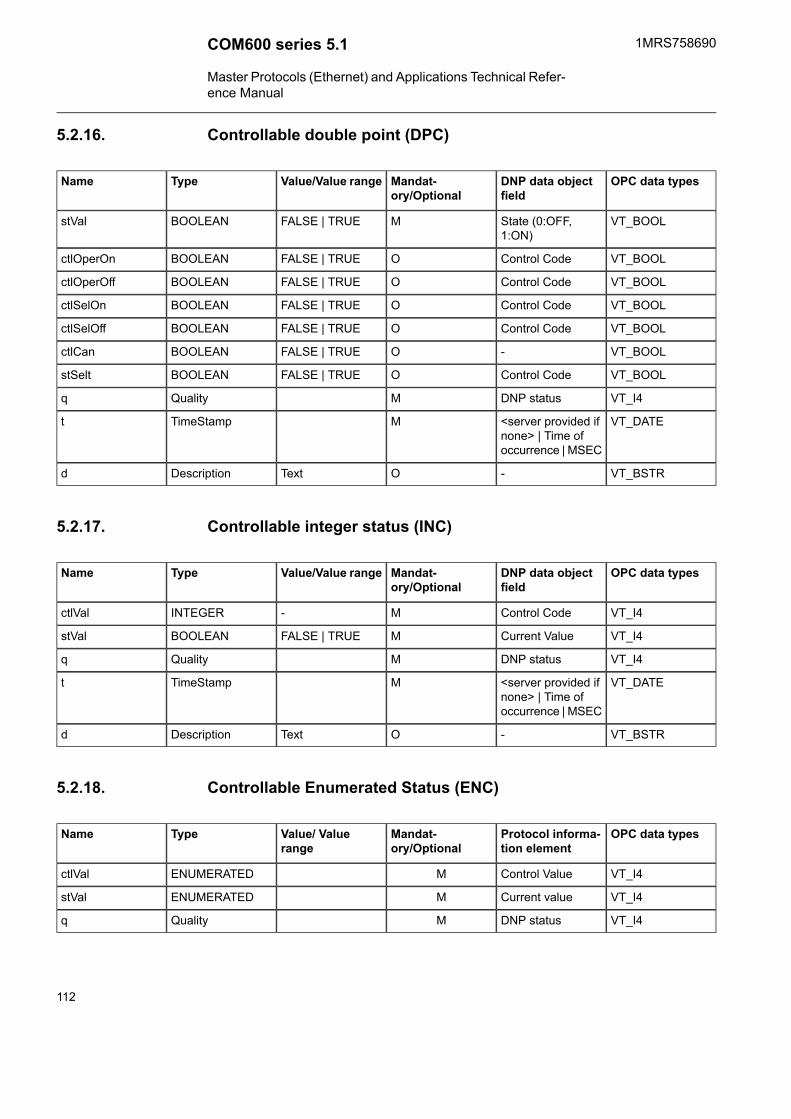
Controllable double point (DPC)5.2.16.
OPC data typesDNP data objectfield
Mandat-ory/Optional
Value/Value rangeTypeName
VT_BOOLState (0:OFF,1:ON)
MFALSE | TRUEBOOLEANstVal
VT_BOOLControl CodeOFALSE | TRUEBOOLEANctlOperOn
VT_BOOLControl CodeOFALSE | TRUEBOOLEANctlOperOff
VT_BOOLControl CodeOFALSE | TRUEBOOLEANctlSelOn
VT_BOOLControl CodeOFALSE | TRUEBOOLEANctlSelOff
VT_BOOL-OFALSE | TRUEBOOLEANctlCan
VT_BOOLControl CodeOFALSE | TRUEBOOLEANstSelt
VT_I4DNP statusMQualityq
VT_DATE<server provided ifnone> | Time ofoccurrence | MSEC
MTimeStampt
VT_BSTR-OTextDescriptiond
Controllable integer status (INC)5.2.17.
OPC data typesDNP data objectfield
Mandat-ory/Optional
Value/Value rangeTypeName
VT_I4Control CodeM-INTEGERctlVal
VT_I4Current ValueMFALSE | TRUEBOOLEANstVal
VT_I4DNP statusMQualityq
VT_DATE<server provided ifnone> | Time ofoccurrence | MSEC
MTimeStampt
VT_BSTR-OTextDescriptiond
Controllable Enumerated Status (ENC)5.2.18.
OPC data typesProtocol informa-tion element
Mandat-ory/Optional
Value/ Valuerange
TypeName
VT_I4Control ValueMENUMERATEDctlVal
VT_I4Current valueMENUMERATEDstVal
VT_I4DNP statusMQualityq
112
1MRS758690COM600 series 5.1
Master Protocols (Ethernet) and Applications Technical Refer-ence Manual

OPC data typesProtocol informa-tion element
Mandat-ory/Optional
Value/ Valuerange
TypeName
VT_DATE<none> | Time ofoccurrence
MTimestampt
VT_BSTRODescriptiond
Binary controlled step position information (BSC)5.2.19.
OPC data typesDNP data objectfield
Mandat-ory/Optional
Value/Value rangeTypeName
VT_I1Control CodeMstop (0) | lower (1)| higher (2) |reserved (3)
ENUMERATEDctlVal
VT_I4StateMValWithTransvalWTr
VT_I4DNP statusMQualityq
VT_DATE<server provided ifnone> | Time ofoccurrence | MSEC
MTimeStampt
VT_BSTR-OTextDescriptiond
Integer controlled step position information (ISC)5.2.20.
OPC data typesDNP data objectfield
Mandat-ory/Optional
Value/Value rangeTypeName
VT_I1Control CodeM-64 … 63INTEGERctlVal
VT_I4StateMValWithTransvalWTr
VT_I4DNP statusMQualityq
VT_DATE<server provided ifnone> | Time ofoccurrence | MSEC
MTimeStampt
VT_BSTR-OTextDescriptiond
Analogue set point (APC)5.2.21.
OPC data typesProtocol informa-tion element
Mandatory /Optional
Value / Valuerange
TypeName
VT_R4Control ValueMAnalogueValuectlVal
VT_R4Current valueMAnalogueValuemxVal
113
COM600 series 5.11MRS758690
Master Protocols (Ethernet) and Applications Technical Refer-ence Manual

VT_I4DNP statusMQualityq
VT_DATE<none> | Time ofoccurrence
MTimestampt
VT_BSTRODescriptiond
114
1MRS758690COM600 series 5.1
Master Protocols (Ethernet) and Applications Technical Refer-ence Manual
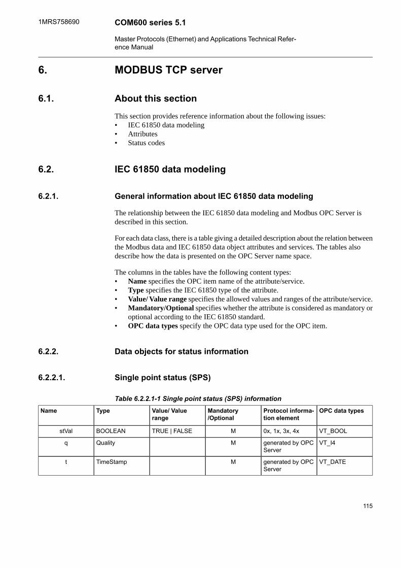
MODBUS TCP server6.
About this section6.1.
This section provides reference information about the following issues:• IEC 61850 data modeling• Attributes• Status codes
IEC 61850 data modeling6.2.
General information about IEC 61850 data modeling6.2.1.
The relationship between the IEC 61850 data modeling and Modbus OPC Server isdescribed in this section.
For each data class, there is a table giving a detailed description about the relation betweenthe Modbus data and IEC 61850 data object attributes and services. The tables alsodescribe how the data is presented on the OPC Server name space.
The columns in the tables have the following content types:• Name specifies the OPC item name of the attribute/service.• Type specifies the IEC 61850 type of the attribute.• Value/ Value range specifies the allowed values and ranges of the attribute/service.• Mandatory/Optional specifies whether the attribute is considered as mandatory or
optional according to the IEC 61850 standard.• OPC data types specify the OPC data type used for the OPC item.
Data objects for status information6.2.2.
Single point status (SPS)6.2.2.1.
Table 6.2.2.1-1 Single point status (SPS) informationOPC data typesProtocol informa-
tion elementMandatory/Optional
Value/ Valuerange
TypeName
VT_BOOL0x, 1x, 3x, 4xMTRUE | FALSEBOOLEANstVal
VT_I4generated by OPCServer
MQualityq
VT_DATEgenerated by OPCServer
MTimeStampt
115
COM600 series 5.11MRS758690
Master Protocols (Ethernet) and Applications Technical Refer-ence Manual

OPC data typesProtocol informa-tion element
Mandatory/Optional
Value/ Valuerange
TypeName
VT_BSTR-OTextDescriptiond
Double point status (DPS)6.2.2.2.
Table 6.2.2.2-1 Double point status (DPS) informationOPC data typesProtocol informa-
tion elementMandatory/Optional
Value/ Valuerange
TypeName
VT_I40x, 1x, 3x, 4xMIntermediate-state(0) optional
off(1)
on(2)
bad-state (3)optional
CPTstVal
VT_I4generated by OPCServer
MQualityq
VT_DATEgenerated by OPCServer
MTimeStampt
VT_BSTROTextDescriptiond
Integer status (INS)6.2.2.3.
Table 6.2.2.3-1 Integer status (INS) informationOPC data typesProtocol informa-
tion elementMandat-ory/Optional
Value/ Valuerange
TypeName
VT_I43x, 4xMINTEGERstVal
VT_I4generated by OPCServer
MQualityq
VT_DATEgenerated by OPCServer
MTimeStampt
VT_BSTROTextDescriptiond
Enumerated Status (ENS)6.2.2.4.
OPC data typesProtocol informa-tion element
Mandat-ory/Optional
Value/ Valuerange
TypeName
MENUMERATEDstVal
116
1MRS758690COM600 series 5.1
Master Protocols (Ethernet) and Applications Technical Refer-ence Manual

OPC data typesProtocol informa-tion element
Mandat-ory/Optional
Value/ Valuerange
TypeName
VT_I4MQualityq
VT_DATEMTimestampt
VT_BSTROTextDescriptiond
Protection activation information (ACT)6.2.2.5.
OPC/IEC 61850 valueValue from stackModbus value
FALSE0: OFF0: OFF
TRUE1: ON1: ON
Table 6.2.2.5-1 Proptection activation information (ACT)OPC data typesProtocol informa-
tion elementMandat-ory/Optional
Value/ Valuerange
TypeName
VT_BOOL0x, 1xMBOOLEANgeneral
VT_BOOL0x, 1xOBOOLEANphsA
VT_BOOL0x, 1xOBOOLEANphsB
VT_BOOL0x, 1xOBOOLEANphsC
VT_BOOL0x, 1xOBOOLEANneut
generated by OPCServer
MTimeStampt
VT_BSTRSeparate signalOTextDescriptiond
Binary counter reading (BCR)6.2.2.6.
BCR information is obtained from any valid Modbus register. Consult the Modbus pro-tocol document for the register address and if they are available for each relay.
Table 6.2.2.6-1 Binary counter reading (BCR) informationOPC data typesModbus registerMandat-
ory/OptionalValue/ Valuerange
TypeName
VT_I43x, 4xMINTEGERactVal
VT_I4ConfigOIntegersiUnit
VT_I4ConfigOIntegermultiplier
VT_BSTRConfigOStringunit
VT_I4generated by OPCServer
MQualityq
117
COM600 series 5.11MRS758690
Master Protocols (Ethernet) and Applications Technical Refer-ence Manual
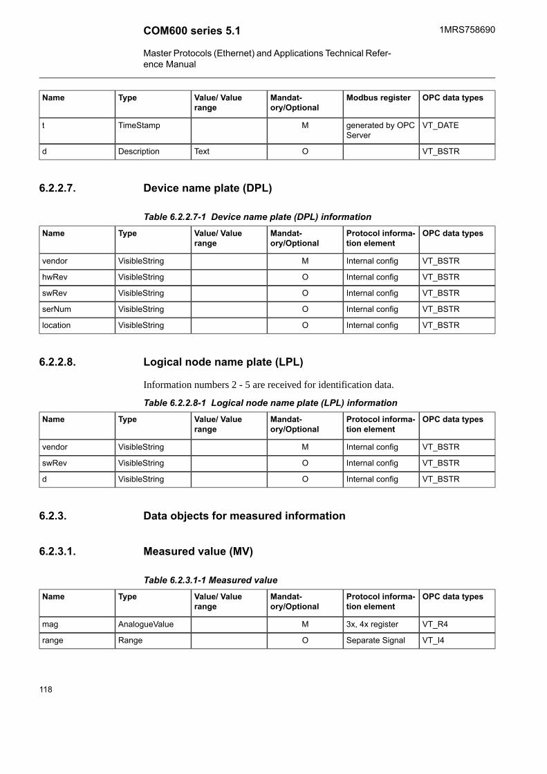
OPC data typesModbus registerMandat-ory/Optional
Value/ Valuerange
TypeName
VT_DATEgenerated by OPCServer
MTimeStampt
VT_BSTROTextDescriptiond
Device name plate (DPL)6.2.2.7.
Table 6.2.2.7-1 Device name plate (DPL) informationOPC data typesProtocol informa-
tion elementMandat-ory/Optional
Value/ Valuerange
TypeName
VT_BSTRInternal configMVisibleStringvendor
VT_BSTRInternal configOVisibleStringhwRev
VT_BSTRInternal configOVisibleStringswRev
VT_BSTRInternal configOVisibleStringserNum
VT_BSTRInternal configOVisibleStringlocation
Logical node name plate (LPL)6.2.2.8.
Information numbers 2 - 5 are received for identification data.
Table 6.2.2.8-1 Logical node name plate (LPL) informationOPC data typesProtocol informa-
tion elementMandat-ory/Optional
Value/ Valuerange
TypeName
VT_BSTRInternal configMVisibleStringvendor
VT_BSTRInternal configOVisibleStringswRev
VT_BSTRInternal configOVisibleStringd
Data objects for measured information6.2.3.
Measured value (MV)6.2.3.1.
Table 6.2.3.1-1 Measured valueOPC data typesProtocol informa-
tion elementMandat-ory/Optional
Value/ Valuerange
TypeName
VT_R43x, 4x registerMAnalogueValuemag
VT_I4Separate SignalORangerange
118
1MRS758690COM600 series 5.1
Master Protocols (Ethernet) and Applications Technical Refer-ence Manual

OPC data typesProtocol informa-tion element
Mandat-ory/Optional
Value/ Valuerange
TypeName
VT_I4generated by OPCServer
MQualityq
VT_DATEgenerated by OPCServer
MTimeStampt
VT_BSTRInternal configOTextDescriptiond
VT_R4Internal configOREALhhLim
VT_R4Internal configOREALhlim
VT_R4Internal configOREALIILim
VT_R4Internal configOREALILim
VT_R4Internal configOREALmin
VT_R4Internal configOREALmax
VT_I4Internal configOIntegersiUnit
VT_I4Internal configOIntegermultiplier
VT_BSTRInternal configOStringunit
VT_I4Internal configOIntegernumOfDec
WYE6.2.3.2.
WYE values are extracted using the same method as MV.
Table 6.2.3.2-1 WYEOPC data typesProtocol information
elementM/OValue/
Valuerange
TypeName
VT_R43x, 4xMAnalogueValuephsA.mag
VT_R43x, 4xMAnalogueValuephsA.ang
VT_I4set by OPC serverMQualityphsA.q
VT_DATEset by OPC serverMTimeStampphsA.t
VT_I4Internal configORangephsA.range
VT_R4Internal configOREALphsA.hhLim
VT_R4Internal configOREALphsA.hLim
VT_R4Internal configOREALphsA.lLim
VT_R4Internal configOREALphsA.llLim
VT_R4Internal configOREALphsA.min
VT_R4Internal configOREALphsA.max
VT_I4Internal configOENUMRATEDphsA.siUnit
119
COM600 series 5.11MRS758690
Master Protocols (Ethernet) and Applications Technical Refer-ence Manual

OPC data typesProtocol informationelement
M/OValue/Valuerange
TypeName
VT_I4Internal configOENUMERATEDphsA.multiplier
VT_BSTRInternal configOStringphsA.unit
VT_R43x, 4xOAnalogueValuephsB.mag
VT_R43x, 4xOAnalogueValue
VT_I4set by OPC serverOQualityphsB.q
VT_DATEset by OPC serverOTimeStampphsB.t
VT_I4Internal configORangephsB.range
VT_R4Internal configOREALphsB.hhLim
VT_R4Internal configOREALphsB.hLim
VT_R4Internal configOREALphsB.lLim
VT_R4Internal configOREALphsB.llLim
VT_R4Internal configOREALphsB.min
VT_R4Internal configOREALphsB.max
VT_I4Internal configOENUMRATEDphsB.siUnit
VT_I4Internal configOENUMERATEDphsB.multiplier
VT_BSTRInternal configOStringphsB.unit
VT_R43x, 4xOAnalogueValuephsC.mag
VT_R43x, 4xOAnalogueValuephsC.ang
VT_I4set by OPC serverOQualityphsC.q
VT_DATEset by OPC serverOTimeStampphsC.t
VT_I4Internal configORangephsC.range
VT_R4Internal configOREALphsC.hhLim
VT_R4Internal configOREALphsC.hLim
VT_R4Internal configOREALphsC.lLim
VT_R4Internal configOREALphsC.llLim
VT_R4Internal configOREALphsC.min
VT_R4Internal configOREALphsC.max
VT_I4Internal configOENUMRATEDphsC.siUnit
VT_I4Internal configOENUMERATEDphsC.multiplier
VT_BSTRInternal configOStringphsC.unit
VT_R43x, 4xOAnalogueValueneut.mag
VT_R43x, 4xOAnalogueValueneut.ang
VT_I4set by OPC serverOQualityneut.q
120
1MRS758690COM600 series 5.1
Master Protocols (Ethernet) and Applications Technical Refer-ence Manual

OPC data typesProtocol informationelement
M/OValue/Valuerange
TypeName
VT_DATEOTimeStampneut.t
VT_I4Internal configORangeneut.range
VT_R4Internal configOREALneut.hhLim
VT_R4Internal configOREALneut.hLim
VT_R4Internal configOREALneut.lLim
VT_R4Internal configOREALneut.llLim
VT_R4Internal configOREALneut.min
VT_R4Internal configOREALneut.max
VT_I4Internal configOENUMRATEDneut.siUnit
VT_I4Internal configOENUMERATEDneut.multiplier
VT_BSTRInternal configOStringneut.unit
VT_BSTRInternal configODescriptiond
Delta (DEL)6.2.3.3.
DEL values are extracted using the same method as MV.
Table 6.2.3.3-1 DeltaOPC data typesModbus registerM/OValue/ Value
rangeTypeName
VT_R43x, 4x registerMAnalogueValuephsAB.mag
VT_R43x, 4x registerMAnalogueValuephsAB.ang
VT_I4set by OPC serverMQualityphsAB.q
VT_DATEset by OPC serverMTimeStampphsAB.t
VT_I4Internal configORangephsAB.range
VT_R4Internal configOREALphsAB.hhLim
VT_R4Internal configOREALphsAB.hLim
VT_R4Internal configOREALphsAB.lLim
VT_R4Internal configOREALphsAB.llLim
VT_R4Internal configOREALphsAB.min
VT_R4Internal configOREALphsAB.max
VT_I4Internal configOENUMRATEDphsAB.siUnit
VT_I4Internal configOENUMERATEDphsAB.multiplier
VT_BSTRInternal configOStringphsAB.unit
121
COM600 series 5.11MRS758690
Master Protocols (Ethernet) and Applications Technical Refer-ence Manual

OPC data typesModbus registerM/OValue/ Valuerange
TypeName
VT_R43x, 4x registerMAnalogueValuephsBC.mag
VT_R43x, 4x registerMAnalogueValuephsBC.ang
VT_I4set by OPC serverMQualityphsBC.q
VT_DATEset by OPC serverMTimeStampphsBC.t
VT_I4Internal configORangephsBC.range
VT_R4Internal configOREALphsBC.hhLim
VT_R4Internal configOREALphsBC.hLim
VT_R4Internal configOREALphsBC.lLim
VT_R4Internal configOREALphsBC.llLim
VT_R4Internal configOREALphsBC.min
VT_R4Internal configOREALphsBC.max
VT_I4Internal configOENUMRATEDphsBC.siUnit
VT_I4Internal configOENUMERATEDphsBC.multiplier
VT_BSTRInternal configOStringphsBC.unit
VT_R43x, 4x registerMAnalogueValuephsCA.mag
VT_R43x, 4x registerMAnalogueValuephsCA.ang
VT_I4set by OPC serverMQualityphsCA.q
VT_DATEset by OPC serverMTimeStampphsCA.t
VT_I4Internal configORangephsCA.range
VT_R4Internal configOREALphsCA.hhLim
VT_R4Internal configOREALphsCA.hLim
VT_R4Internal configOREALphsCA.lLim
VT_R4Internal configOREALphsCA.llLim
VT_R4Internal configOREALphsCA.min
VT_R4Internal configOREALphsCA.max
VT_I4Internal configOENUMRATEDphsCA.siUnit
VT_I4Internal configOENUMERATEDphsCA.multiplier
VT_BSTRInternal configOStringphsCA.unit
VT_BSTRInternal configOTextDescriptiond
122
1MRS758690COM600 series 5.1
Master Protocols (Ethernet) and Applications Technical Refer-ence Manual

Data objects for controllable status information6.2.4.
Controllable single point (SPC)6.2.4.1.
The command sequence for controlling points is specific to each relay. In the 2000 Rproducts, for example, SPC is implemented using a bit mask.
TRUE/FALSE values are sent with 1 and 0 values.
Underlying protocol converter stack uses Motorola convention in binary value usage.Used OPC Server sees OFF data with value 0 and ON data with value 1 from stack.
OPC/IEC 61850 valueValue from stackModbus value
FALSE0:OFF0 (OFF default)
TRUE1:ON1 (ON default)
OPC DataType
M/OValue / Valuerange
TypeName
VT_BOOL0x, 4xMFALSE |TRUE
BOOLEANctlVal
VT_BOOL0x, 1x, 3x, 4xMFALSE |TRUE a>
BOOLEANstVal
VT_I4generated byOPC Server
MQualityq
VT_DATEgenerated byOPC Server
MTimeStampt
VT_BSTRInternal configOTextDescriptiond
Controllable double point (DPC)6.2.4.2.
Table 6.2.4.2-1 Controllable double pointOPC Data TypesModbus informa-
tion elementM/OValue / Value
RangeSCOName
VT_BOOL0x, 4xOFALSE|TRUESPIctlOperOn
VT_BOOL0x, 4xOFALSE|TRUEctlOperOff
VT_BOOL0x, 4xOFALSE|TRUEctlSelOn
VT_BOOL0x, 4xOFALSE|TRUEctlSelOff
VT_I40x, 1x, 3x, 4xMIntermediate-state(0) | off (1) | on (2)| bad-state (3)
CPTstVal
VT_I44x registerMQualityq
123
COM600 series 5.11MRS758690
Master Protocols (Ethernet) and Applications Technical Refer-ence Manual

OPC Data TypesModbus informa-tion element
M/OValue / ValueRange
SCOName
VT_DATEgenerated by OPCServer
MTimeStampt
VT_BOOL0x, 4xOFALSE|TRUEBOOLEANctlCan
VT_BOOLgenerated by OPCServer
OFALSE|TRUEBOOLEANstSeld
VT_BSTRSeparate signalOTextDescriptiond
Controllable integer status (INC)6.2.4.3.
Table 6.2.4.3-1 Controllable integer status (INC) informationOPC data typesModbus registerMandat-
ory/OptionalValue/ Valuerange
TypeName
VT_I44xMINTEGERctlVal
VT_I43x, 4xMINTEGERstVal
VT_I4Generated by OPCserver
MQualityq
VT_DATEGenerated by OPCserver
MTimeStampt
VT_BSTRInternal configOTextDescriptiond
Controllable Enumerated Status (ENC)6.2.4.4.
OPC data typesProtocol informa-tion element
Mandat-ory/Optional
Value/ Valuerange
TypeName
VT_I44xMENUMERATEDctlVal
VT_I43x, 4xMENUMERATEDstVal
VT_I4generated by OPCserver
MQualityq
VT_DATEgenerated by OPCserver
MTimestampt
VT_BSTROTextDescriptiond
124
1MRS758690COM600 series 5.1
Master Protocols (Ethernet) and Applications Technical Refer-ence Manual

Binary controlled step position information (BSC)6.2.4.5.
Table 6.2.4.5-1 Binary controlled step position information (BSC)OPC data typesModbus registerM/OValue/ Value
rangeTypeName
VT_I10xMstop (0) | lower (1)| higher (2) |reserved (3)
ENUMERATEDctlVal
3x, 4xMValWithTransvalWTr
VT_I4Generated by OPCserver
MQualityq
VT_DATEGenerated by OPCserver
MTimeStampt
VT_BSTRInternal configOTextDescriptiond
Integer controlled step position information (ISC)6.2.4.6.
Table 6.2.4.6-1 Integer controlled step position information (ISC)OPC data typesModbus registerMandat-
ory/OptionalValue/ Valuerange
TypeName
VT_I14xM-64 ... 63INTEGERctlVal
VT_I43x, 4xMValWithTransvalWTr
VT_I4Generated by OPCserver
MQualityq
VT_DATEGenerated by OPCserver or INC copy
MTimeStampt
VT_BSTRInternal configOTextDescriptiond
Data objects for controllable analogue information6.2.5.
Analogue set point (APC)6.2.5.1.
Table 6.2.5.1-1 Analogue set point (APC) informationOPC data typesModbus registerMandat-
ory/OptionalValue/ Valuerange
TypeName
VT_REAL4xMINTEGERspMag
VT_I4Generated by OPCserver
MQualityq
125
COM600 series 5.11MRS758690
Master Protocols (Ethernet) and Applications Technical Refer-ence Manual

OPC data typesModbus registerMandat-ory/Optional
Value/ Valuerange
TypeName
VT_DATEGenerated by OPCserver
MTimeStampt
VT_BSTRInternal configOTextDescriptiond
Attributes6.3.
Server attributes6.3.1.
Table 6.3.1-1 Server attributesDescriptionValue or Value range/ DefaultName
Data type: Text
Access: Read-only
Version information of the protocol stack
Value: Version informationProtocol stack ver-sion
The Reset button for resetting the OPCServer
Reset
File version of the executable OPC ServerFile version
Version information of the installed OPCServer
Product version
126
1MRS758690COM600 series 5.1
Master Protocols (Ethernet) and Applications Technical Refer-ence Manual

Modbus channel attributes6.3.2.
Table 6.3.2-1 Modbus channel attributesDescriptionValue or Value range/ DefaultName
Data type: Integer
Access: No limitations
The state of the line - whetherit is in use or not. When a lineis not in use, no data can betransmitted on it, and no datais received from it. The lineattributes can be read as usual.Generally, a line must be takenout of use by setting this attrib-ute to 0 before the line attrib-utes can be written. When aline is stopped by setting the IUattribute = 0, all data transmis-sion on the line ceases. How-ever, before that, the protocolstack executes to the end allon-going data transactions. Forexample, the polling of the sta-tion in turn is completed.
0 = Not in use, the line commu-nication is stopped
1 = In use
Default: 1
In use
Data type: Integer
Access: Read-only
Diagnostic counters(TCPchannel)
The number of transmittedtelegrams.
Transmitted telegrams
Incremented each time a mes-sage transmission to the Mod-bus channel fails for somereason.
Failed transmissions
The number of transmittedcommands.
Transmitted commands
The number of transmittedreplies.
Transmitted replies
Incremented each time theModbus OPC Server receivesa message from the Modbuschannel.
Received messages
The number of times there hasbeen a buffer overflow.
Buffer overflow errors
Number of TCP connectionrequests.
TCP connect
Number of accepted TCP con-nection requests
TCP accept
127
COM600 series 5.11MRS758690
Master Protocols (Ethernet) and Applications Technical Refer-ence Manual

DescriptionValue or Value range/ DefaultName
Number of TCP connectionclose requests
TCP close
Modbus Device attributes6.3.3.
Table 6.3.3-1 Modbus device attributesDescriptionValue or Value range/ DefaultName
Data type: Integer
Access: No limitations
The operational status of thedevice - in use or out of use.Taking the device out of usewith this attribute stops all datacommunication with the device.All operations that would resultin data exchange are disabled.The device itself is not affectedby the attribute, only the pro-tocol stack’s image of thedevice. Setting IU to 1 isallowed only if the deviceaddress is legal.
0 = Out of use
1 = In use
Default: 1
In use
Data type: Integer
Access: No limitations
Indicates the detailed informa-tion about the station devicestatus. Writing to the OS attrib-ute (OS = 1) of a device makesthe protocol stack to re-transmitthe last system messagecaused by the device. Possible"Stopped" and "Suspended"messages cause old markingof OPC items. By reading theOS attribute, the status code ofthe system message can beread.
See the Status Codes manualfor detailed information.
1 = Re-transmit system mes-sage
A status code, for example:
0 = OK (communication worksproperly)
13801 = Device suspended
Object status
Data type: Boolean
Access: Read-only
Indicates the status of thedevice connection.
True = Device connection OK
False = Device connectionsuspended
Device connection status
128
1MRS758690COM600 series 5.1
Master Protocols (Ethernet) and Applications Technical Refer-ence Manual
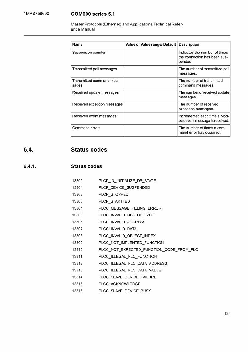
DescriptionValue or Value range/ DefaultName
Indicates the number of timesthe connection has been sus-pended.
Suspension counter
The number of transmitted pollmessages.
Transmitted poll messages
The number of transmittedcommand messages.
Transmitted command mes-sages
The number of received updatemessages.
Received update messages
The number of receivedexception messages.
Received exception messages
Incremented each time a Mod-bus event message is received.
Received event messages
The number of times a com-mand error has occurred.
Command errors
Status codes6.4.
Status codes6.4.1.
PLCP_IN_INITIALIZE_DB_STATE13800
PLCP_DEVICE_SUSPENDED13801
PLCP_STOPPED13802
PLCP_STARTTED13803
PLCC_MESSAGE_FILLING_ERROR13804
PLCC_INVALID_OBJECT_TYPE13805
PLCC_INVALID_ADDRESS13806
PLCC_INVALID_DATA13807
PLCC_INVALID_OBJECT_INDEX13808
PLCC_NOT_IMPLENTED_FUNCTION13809
PLCC_NOT_EXPECTED_FUNCTION_CODE_FROM_PLC13810
PLCC_ILLEGAL_PLC_FUNCTION13811
PLCC_ILLEGAL_PLC_DATA_ADDRESS13812
PLCC_ILLEGAL_PLC_DATA_VALUE13813
PLCC_SLAVE_DEVICE_FAILURE13814
PLCC_ACKNOWLEDGE13815
PLCC_SLAVE_DEVICE_BUSY13816
129
COM600 series 5.11MRS758690
Master Protocols (Ethernet) and Applications Technical Refer-ence Manual

PLCC_NEGATIVE_ACKNOWLEDGE13817
PLCC_MEMORY_PARITY_ERROR13818
PLCC_UNKNOWN_DIAGNOSTIC_COUNTER13819
PLCC_INVALID_TOPIC_NUMBER13820
PLCC_INVALID_OBJECT_ADDRESS13821
PLCC_INVALID_OBJECT_FORMAT13822
PLCC_SC_DATA_OVERFLOW13823
PLCC_INVALID_INDEX_RANGE13824
PLCC_UNKNOWN_ATTRIBUTE13825
PLCC_LOCAL_RESPONSE13826
PLCP_TIMEOUT_WHILE_WAITING_RESPONSE13827
PLCP_EVENT_BUFFER_OK13828
PLCP_EVENT_BUFFER_OVERFLOW13829
PLCP_EVENT_BUFFER_ERROR13830
PLCC_UNKNOWN_FUNCTION13831
PLCC_NO_ADDITIONAL_DATA_AVAILABLE13832
PLCC_INVALID_ATTRIBUTE_VALUE13833
PLCC_INTERNAL_ERROR13834
130
1MRS758690COM600 series 5.1
Master Protocols (Ethernet) and Applications Technical Refer-ence Manual

Redundant OPC server7.
Introduction7.1.
The Redundant OPC server allows the user to have Redundant IED objects, where eachRedundant IED object encapsulates the data of two source IED objects with identicaldata object configuration.
One of the source IEDs is set as the active source of the Redundant IED, which will thenact as if it was that source IED. The Redundant IED forwards indication and measurementdata from the active source IED, and sends received commands to it.
It’s possible for the user to switch the active source between the two source IEDs ondemand, for example when the currently active source IED loses connection or havesome other mishap, or is simply taken down for maintenance.
The source OPC server and IEDs are required to follow the common IEC-61850 dataobject model used in COM600, otherwise there are no limitations. There is special supportin SAB600 for making redundant configurations with SSC600, though.
Redundant OPC Server Properties7.2.
Table 7.2-1 Redundant OPC Server PropertiesDescriptionDefaultRedundant OPC Server
Caption
Description
Enables the use of remotenode names
FalseUse Remote Node Names
Redundant Subnet Properties7.3.
DescriptionDefaultRedundant Subnet
Caption
Description
Controls if the device commu-nication is initially in use or not
In Use
Not In Use
In Use
131
COM600 series 5.11MRS758690
Master Protocols (Ethernet) and Applications Technical Refer-ence Manual

Redundant IED Properties7.4.
DescriptionDefaultRedundant IED
Caption
Description
Specifies whether diagnosticsare enabled.
False
True
Diagnostics Enabled
Specifies whether IED is in useor not.
In Use
Not In Use
In Use
Defines whether IED is used insimulation mode.
False
True
Simulation Mode
Source 1
OPC item path for source 1 IEDSource 1 IED Path
ProgID of source 1 OPC ServerSource 1 ProgID
Remote node name of source1
localhostSource 1 Remote Node Name
Initialization time for source 1OPC Server
0(0-65535)Source 1 Server InitializationTime
Tree delimiter of source 1 OPCServer
\Source 1 Tree Delimiter
Source 2
OPC item path for source 2 IEDSource 2 IED Path
ProgID of source 2 OPC ServerSource 2 ProgID
Remote node name of source2
localhostSource 2 Remote Node Name
Initialization time for source 2OPC Server
0(0-65535)Source 2 Server InitializationTime
Tree delimiter of source 2 OPCServer
\Source 2 Tree Delimiter
Active Source
Default value for active source.
Value 0 refers to Source 1 andValue 1 refers to Source 2.
0(0-1)Active Source Default
Event reference for activesource switch
ActiveSourceSwitchActive Source Event Class
Refresh interval for activesource indication
0 (0-65535)Active Source Refresh Interval
Active Source Input Signal
132
1MRS758690COM600 series 5.1
Master Protocols (Ethernet) and Applications Technical Refer-ence Manual

DescriptionDefaultRedundant IED
Initialization time in seconds forOPC server containing activesource input signal
0 (0-65535)Active Source Input Initializa-tion Time
OPC Item path for activesource external input signal
Active Source Input Item Path
ProgID for OPC server contain-ing the active source input sig-nal.
Active Source Input ProgID
Remote node name for OPCserver containing the activesource input signal
localhostActive Source Input RemoteNode name
Scale for active source inputsignal
Active Source Input Scale
Consistency Checking
Specifies whether the quality ofthe data is changed (down-graded) when consistencycheck fails
True
False
Consistency Change Quality
Enables consistency checking.False
True
Consistency Checking Enabled
By default, compare value forthe specified CDCs.
ACT,ACD,SPC,DPCConsistency Compare ValueFor
By default, compare value andquality for the specified CDCs.
Consistency Compare Value-Quality For
By default, compare value,quality and time for the spe-cified CDCs.
Consistency Compare Value-Quality-Timestamp For
The default timestamp epsilonin milliseconds.
20Consistency Default TimeEpsilon
The severity of generated con-sistency failure events.
500(0-65535)Consistency Event Severity
Specifies if the generated con-sistency failure events targetsthe substation structure or not.
True
False
Consistency Generate Substa-tion
The minimum time in secondsthat must elapse before a newupdate can be checked.
900Consistency Minimum CheckAge
The alarm/event definition touse for failed consistencychecking status. Will be activ-ated when there is inconsistentdata.
ConsistencyStatusConsistency Status AlarmClass
Alarm and Event
133
COM600 series 5.11MRS758690
Master Protocols (Ethernet) and Applications Technical Refer-ence Manual

DescriptionDefaultRedundant IED
Device Connection StatusDevice Connection StatusDevice Connection StatusClass
Redundant Data Object Properties7.5.
Common
OPC source path for the dateobject. Can be left empty if thesource IEDs use samenamespace structure as theRedundant IED.
Data Object Path
Object subtypeREDUNDANTSubType
Defines how often the value isupdated.
0 (0-65535)Update Rate
Consistency checking mode forthis data object.
Disabled
Compare value
Compare value and quality
Compare value, quality andtimestamp
Use CDC default mode
Consistency Checking Mode
The largest time difference inmilliseconds allowed before twotime stamps are consideredinconsistent.
Will use the default time epsilonvalue configured in the IEDwhen zero.
0 (0-65535)Consistency Checking TimeEpsilon
ACD/ACT
Indication event mappingMapped Event for PhaseA/B/C/general/neut
Scale for phase signalIndication Scale (A/B/C/gen-eral/neut)
DPS/ENS/INS/SPS/BCR
Mapped event for indicationsignal.
Indication Event
Scale for Indication signal.Indication Scale
ENC/INC/SPC
Command event mappingCommand Event
134
1MRS758690COM600 series 5.1
Master Protocols (Ethernet) and Applications Technical Refer-ence Manual
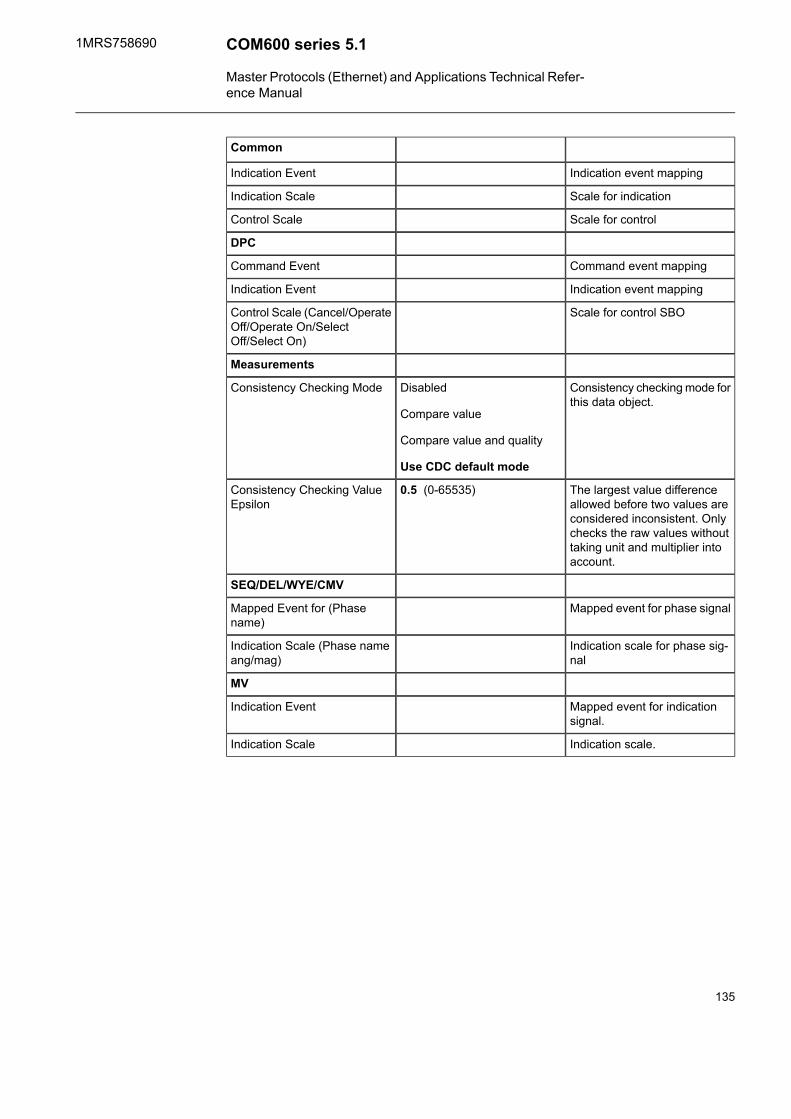
Common
Indication event mappingIndication Event
Scale for indicationIndication Scale
Scale for controlControl Scale
DPC
Command event mappingCommand Event
Indication event mappingIndication Event
Scale for control SBOControl Scale (Cancel/OperateOff/Operate On/SelectOff/Select On)
Measurements
Consistency checking mode forthis data object.
Disabled
Compare value
Compare value and quality
Use CDC default mode
Consistency Checking Mode
The largest value differenceallowed before two values areconsidered inconsistent. Onlychecks the raw values withouttaking unit and multiplier intoaccount.
0.5 (0-65535)Consistency Checking ValueEpsilon
SEQ/DEL/WYE/CMV
Mapped event for phase signalMapped Event for (Phasename)
Indication scale for phase sig-nal
Indication Scale (Phase nameang/mag)
MV
Mapped event for indicationsignal.
Indication Event
Indication scale.Indication Scale
135
COM600 series 5.11MRS758690
Master Protocols (Ethernet) and Applications Technical Refer-ence Manual

Appendix 1
Interoperability list for IEC104 OPC Server
Not supported
Supported
Supported, may need additional engineering
This companion standard presents sets of parameters and alternatives from which subsetsmust be selected to implement particular tele control systems. Certain parameter values,such as the choice of “structured“ or “unstructured“ fields of the Information ObjectAddress (IOA) of ASDUs represent mutually exclusive alternatives. This means thatonly one value of the defined parameters is admitted per system. Other parameters, suchas the listed set of different process information types in command and in monitor direc-tion allow the specification of the complete set or subsets, as appropriate for the applic-ations. This clause summarizes the parameters of the previous clauses to facilitate asuitable selection for a specific application. If a system is composed of equipmentstemming from different manufacturers, it is necessary that all partners agree on theselected parameters.
The interoperability list is defined as in the IEC 60870-5-104 protocol and extended withparameters used in this standard. The text descriptions of parameters which are notapplicable to this companion standard are struck out (the corresponding check box ismarked black).
The full specification of a system can require individualselection of certain parameters for certain parts of the system,for example, individual selection of scaling factors for indi-vidually addressable measured values.
Application layer telegram formats
Function or ASDU is not used
Function or ASDU is used as standardized (default)
Function or ASDU is used in reverse mode
Function or ASDU is used in standard and reverse mode
Function or ASDU can need some additional application level work
136
1MRS758690COM600 series 5.1
Master Protocols (Ethernet) and Applications Technical Refer-ence Manual

The possible selection (blank, X, R, B or A) is specified for each specific clause orparameter. A black check box indicates that the option cannot be selected in this com-panion standard.
Device function (system-specific parameter)
System definition
Controlling station (Master)
Controlled station (Slave)
Network configuration (network-specific parameter)
Multipoint partylinePoint to point
Multipoint starMultiple point to point
Physical layer (network-specific parameter)
Transmission speed (control direction)
Balanced interchange circuitX.24/X.27
Unbalanced interchange cir-cuit V.24/V.28 Recommendedif > 1200 bit/s
Unbalanced interchange cir-cuit V.24/V.28 Standard
2400 bit/s2400 bit/s400 bit/s
4800 bit/s4800 bit/s200 bit/s
9600 bit/s9600 bit/s300 bit/s
19200 bit/s600 bit/s
38400 bit/s4200 bit/s
56000 bit/s
64000 bit/s
137
COM600 series 5.11MRS758690
Master Protocols (Ethernet) and Applications Technical Refer-ence Manual

Transmission speed (monitor direction)
Balanced interchange circuitX.24/X.27
Unbalanced interchange cir-cuit V.24/V.28 Recommendedif > 1200 bit/s
Unbalanced interchange cir-cuit V.24/V.28 Standard
2400 bit/s2400 bit/s400 bit/s
4800 bit/s4800 bit/s200 bit/s
9600 bit/s9600 bit/s300 bit/s
19200 bit/s600 bit/s
38400 bit/s4200 bit/s
56000 bit/s
64000 bit/s
Link layer (network-specific parameter)
Frame format FT 1.2, signel character 1 and the fixed time out interval are used exclus-ively in this companion standard.
Address field of the linkLink transmission procedure
not present (balanced transmissiononly)
Balanced transmission
One octetUnbalanced transmission
Two octet
structuredFrame length
unstructuredMaximum length L (number of octets)
When using an unbalanced link layer, the following ASDU types are returned in class2 messages (low priority) with the indicated causes of transmission:
The standard assignment of ASDUs to class 2 messages is used as follows:
Cause of transmissionType identification
<1>9, 11, 13, 21
A special assignment of ASDUs to class 2 messages is used as follows:
Cause of transmissionType identification
138
1MRS758690COM600 series 5.1
Master Protocols (Ethernet) and Applications Technical Refer-ence Manual

Application layer
Transmission mode for application data
Mode 1 (the least significant octet first), as defined in clause 4.10 of IEC 870-5-4, isused exclusively in this companion standard.
Common address of ASDU (system-specific parameter)
Two octetsOne octet
Information object address (system-specific parameter)
structuredOne octet
unstructuredTwo octets
Three octets
Cause of transmission (system-specific parameter)
Two octets (with originator address)One octet
Length of APDU (system-specific parameter)
The maximum length of the APDU is 253 (default). The maximum length can be reducedper system.
Maximum length of APDUper system
Selection of standard ASDUs
Process information in monitor direction (station-specific parameter)
M_SP_NA_1:=Single-point information<1>
M_SP_TA_1:=Single-point information with time tag<2>
M_DP_NA_1:=Double-point information<3>
M_DP_TA_1:=Double-point information with time tag<4>
M_ST_NA_1:=Step position information<5>
139
COM600 series 5.11MRS758690
Master Protocols (Ethernet) and Applications Technical Refer-ence Manual

M_ST_TA_1:=Step position information with time tag<6>
M_BO_NA_1:=Bitstring of 32 bit<7>
M_BO_TA_1:=Bitstring of 32 bit with time tag<8>
M_ME_NA_1:=Measured value, normalized value<9>
M_ME_TA_1:=Measured value, normalized value with time tag<10>
M_ME_NB_1:=Measured value, scaled value<11>
M_ME_TB_1:=Measured value, scaled value with time tag<12>
M_ME_NC_1:=Measured value, short floating point value<13>
M_ME_TC_1:=Measured value, short floating point value with timetag
<14>
M_IT_NA_1:=Integrated totals<15>
M_IT_TA_1:=Integrated totals with time tag<16>
M_EP_TA1:=Event of protection equipment with time tag<17>
M_EP_TB1:=Packed start events of protection equipment withtime tag
<18>
M_EP_TC_1:=Packed output circuit information of protectionequipment with time tag
<19>
M_PS_NA_1:=Packed single point information with time tag<20>
M_ME_ND_1:=Measured value, normalized value without qualitydescriptor
<21>
M_SP_TB_1:=Single-point information with time tag CP56Time2a<30>
M_DP_TB_1:=Double-point information with time tag CP56Time2a<31>
M_ST_TB_1:=Step position information with time tag CP56Time2a<32>
M_BO_TB_1:=Bitstring of 32 bit with time tag CP56Time2a<33>
M_ME_TD_1:=Measured value, normalized value with time tagCP56Time2a
<34>
M_ME_TE_1:=Measured value, scaled value with time tagCP56Time2a
<35>
M_ME_TF_1:=Measured value, short floating point value with timetag CP56Time2a
<36>
M_IT_TB_1:=Integrated totals with time tag CP56Time2a<37>
M_EP_TD_1:=Event of protection equipment with time tagCP56Time2a
<38>
M_EP_TE_1:=Packed start events of protection equipment withtime tag CP56Time2a
<39>
140
1MRS758690COM600 series 5.1
Master Protocols (Ethernet) and Applications Technical Refer-ence Manual

M_EP_TF_1:=Packed output circuit information of protectionequipment with time tag CP56Time2a
<40>
Either the ASDUs of the set <2>, <4>, <6>, <8>, <10>, <12>, <14>, <16>, <17>, <18>,<19> or of the set <30> - <40> are used.
Process information in control direction (station-specific parameter)
C_SC_NA_1:=Single command<45>
C_DC_NA_1:=Double command<46>
C_RC_NA_1:=Regulating step command<47>
C_SE_NA_1:=Set point command, normalized value<48>
C_SC_NB_1:=Set point command, scaled value<49>
C_SC_NC_1:=Set point command, short float point value<50>
C_BO_NA_1:=Bitstring of 32 bit<51>
C_SC_TA_1:=Single command with time tag CP56Time2a<58>
C_DC_TA_1:=Double command with time tag CP56Time2a<59>
C_RC_TA_1:=Regulating step command with time tagCP56Time2a
<60>
C_SE_TA_1:=Set point command, normalized value with time tagCP56Time2a
<61>
C_SE_TB_1:=Set point command, scaled value with time tagCP56Time2a
<62>
C_SE_TC_1:=Set point command, short floating point value withtime tag CP56Time2a
<63>
C_BO_TA_1:=Bitstring of 32 bit with time tag CP56Time2a<64>
Either the ASDUs of the set <45> - <51> or of the set <58> - <64> are used.
System information in monitor direction (station-specific parameter)
M _EI_NA_1:=End of initialization<70>
141
COM600 series 5.11MRS758690
Master Protocols (Ethernet) and Applications Technical Refer-ence Manual

System information in control direction (station-specific parameter)
C_IC_NA_1:=Interrogation command<100>
C_CI_NA_1:=Counter interrogation command<101>
C_RD_NA_1:=Read command<102>
C_CS_NA_1:=Clock synchronization command<103>
C_TS_NA_1:=Test command<104>
C_RP_NA_1:=Reset process command<105>
C_CD_NA_1:=Delay acquisition command<106>
C_TS_TA_1:=Test command with time tag CP56Time2a<107>
Parameter in control direction (station-specific parameter)
P_ME_NA_1:=Parameter of measured value, normalized value<110>
P_ME_NB_1:=Parameter of measured value, scaled value<111>
P_ME_NC_1:=Parameter of measured value, short floating pointvalue
<112>
P_AC_NA_1:=Parameter activation<113>
File transfer (station-specific parameter)
F_FR_NA_1:=File ready<120>
F_SR_NA_1:=Section ready<121>
F_SC_NA_1:=Call directory, select file, call file, call section<122>
F_LS_NA_1:=Last section, last segment<123>
F_AF_NA_1:=Ack file, ack section<124>
F_SG_NA_1:=Segment<125>
F_DR_TA_1:=Directory (blank or X, only available in monitor(standard) direction)
<126>
142
1MRS758690COM600 series 5.1
Master Protocols (Ethernet) and Applications Technical Refer-ence Manual
Type identifier and cause of transmission assignments(station-specific parameters)
• Shaded boxes are not required• Black boxes are not permitted in this companion standard• Blank = Function or ASDU is not used• Mark Type identification/Cause of transmission combinations:
143
COM600 series 5.11MRS758690
Master Protocols (Ethernet) and Applications Technical Refer-ence Manual

• ‘X’ if supported only in the standard direction• ‘R’ if supported only in the reverse direction• ‘B’ if supported in both directions
144
1MRS758690COM600 series 5.1
Master Protocols (Ethernet) and Applications Technical Refer-ence Manual
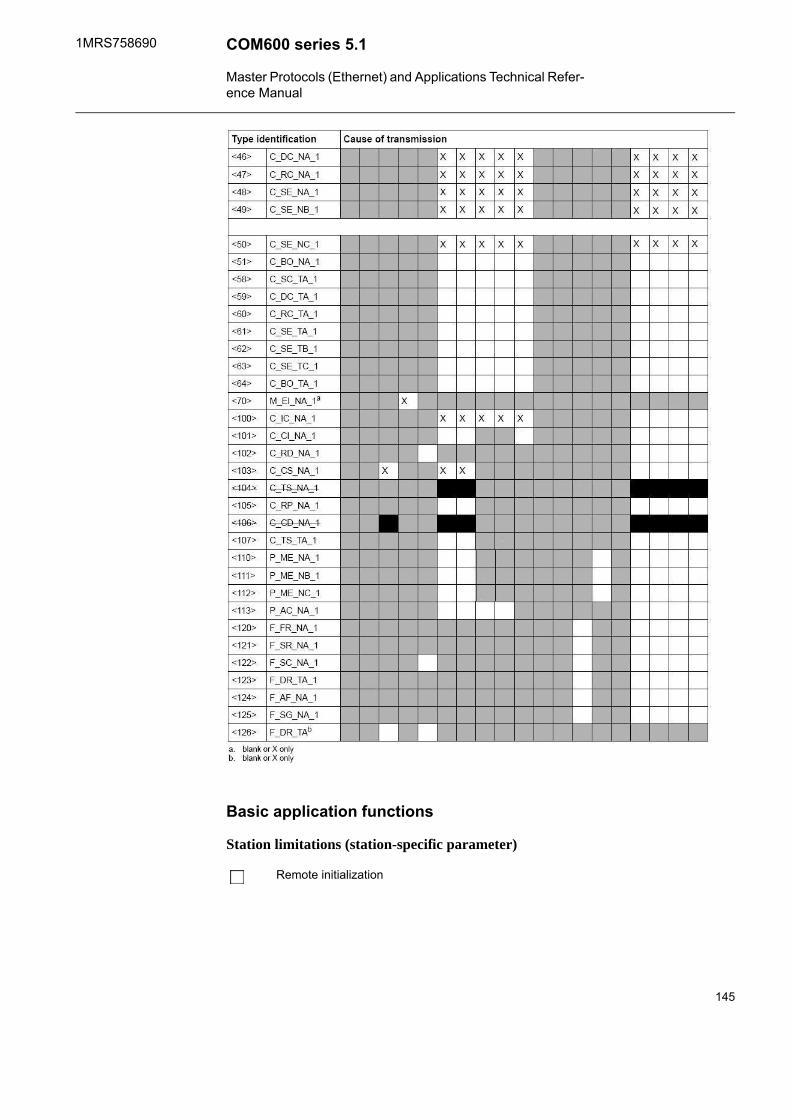
Basic application functions
Station limitations (station-specific parameter)
Remote initialization
145
COM600 series 5.11MRS758690
Master Protocols (Ethernet) and Applications Technical Refer-ence Manual

An indication ASDU “Controlling Station Initialized” sent tothe Controlled Station is not used.
Cyclic data transmission (station-specific parameter)
Cyclic data transmission
Read procedure (station-specific parameter)
Read procedure
Spontaneous transmission (station-specific parameter)
Spontaneous transmission
Double transmission of information objects with cause ofspontaneous transmission (station-specific parameter)
The following type identifications can be transmitted in succession caused by a singlestatus change of an information object. The particular information object addresses forwhich double transmission is enabled are defined in a project-specific list.
Single-point information M_SP_NA1, M_SP_TA_1, M_SP_TB_1 and M_PS_NA_1
Double-point information M_DP_NA_1, M_DP_TA_1 and M_DP_TB_1
Step position information M_ST_NA_1, M_ST_TA_1 and M_ST_TB_1
Bitstring of 32 bit M_BO_NA_1, M_BO_TA_1 and M_BO_TB_1 (if defined for a specificproject)
Measured value, normalized value M_ME_NA_2, M_ME_TA_1, M_ME_ND_ 1 andM_ME_TD_1
Measured value, scaled value M_ME_NB_1, M_ME_TB_1 and M_ME_TE_1
Measured value, short floating point number M_ME_NC_1, M_ME_TC_1 andM_ME_TF_1
146
1MRS758690COM600 series 5.1
Master Protocols (Ethernet) and Applications Technical Refer-ence Manual

Station interrogation (system parameter or station-specific parameter)
global
group 13group 7group 1
group 14group 8group 2
group 15group 9group 3
group 16group 10group 4
group 11group 5
group 12group 6
Clock synchronization (station-specific parameter)
Clock synchronization
Command transmission (object-specific parameter)
Direct command transmission
Direct set point command transmission
Select and execute command
Select and execute set point command
C_SE ACTTERM used
No additional information
Short pulse duration (duration determined by a system parameter in the outstation)
Long pulse duration (duration determined by a system parameter in the outstation)
Persistent output
Supervision of maximum delay in command direction of commands and set point com-mands.
Maximum allowable delay of commands and set point commands255 s
147
COM600 series 5.11MRS758690
Master Protocols (Ethernet) and Applications Technical Refer-ence Manual

Transmission of integrated totals (station parameter or object-specificparameter)
Mode A: Local freeze with spontaneous transmission
Mode B: Local freeze with counter interrogation
Mode C: Freeze and transmit by counter interrogation commands
Mode D: Freeze by counter interrogation command, frozen values reported spontaneously
Counter read
Counter freeze without reset
Counter freeze with reset
Counter reset
General request counter
Request counter group 1
Request counter group 2
Request counter group 3
Request counter group 4
Define addresses per group.
Parameter loading (object-specific parameter)
Threshold value
Smoothing factor
Low limit for transmission of measured value
High limit for transmission measured value
Parameter activation (object-specific parameter)
Act / deact of persistent cyclic or periodic transmission of the addressed object
148
1MRS758690COM600 series 5.1
Master Protocols (Ethernet) and Applications Technical Refer-ence Manual

Test procedure (object-specific parameter)
Test procedure
File transfer (station-specific parameter)
File transfer in monitor direction
Transparent file
Transmission of disturbance data of protection equipment
Transmission of sequences of events
Transmission of sequences of recorded analogue values
File transfer in control direction
Transparent file
Background scan (station-specific parameter)
Background scan
Acquisition of transmission delay (station-specific parameter)
Acquisition of transmission delay
Definition of time-outs
Selected valueRemarksDefault-valueParameter
1 - 255 sTime-out of connection establishment30 st0
1 - 255 sTime-out of send or test APDUs15 st1
1 - 255 sTime-out for acknowledges in case ofno data messages t2 < t1
10 st2
1 - 255 sTime-out for sending test frames incase of a long idle state
20t3
149
COM600 series 5.11MRS758690
Master Protocols (Ethernet) and Applications Technical Refer-ence Manual

Maximum range of values for all the time-outs: 1 seconds to255 seconds , accuracy 1 s.
Maximum number of outstanding I format APDUs (k) and the latestacknowledgment (w)
Selected valueRemarksDefault valueParameter
1-32767 sMaximum differencereceive sequencenumber to send statevariable
12 APDUk
1-32767 sLatest acknowledg-ment after receiving wI-format APDUs
8 APDUsw
Maximum range of values k: 1 to 32767 (215-1) APDUs, accuracy 1 APDU.
Maximum range of values w: 1 to 32767 APDUs, accuracy 1 APDU
(Recommendation: w should not exceed 2/3 of k).
Port number
RemarksDefault valueParameter
In all cases2404Port number
RFC 2200 suite
RFC 2200 is an official Internet standard which describes the state of standardization ofprotocols used on the Internet as determined by the Internet Architecture Board (IAB).It offers a broad spectrum of actual standards used in the Internet. The suitable selectionof documents from RFC 2200 defined in this standard for given projects must be chosenby the user of this standard.
Ethernet 802.3
Serial X.21 interface
Other selection RFC 2200:
List of valid documents from RFC 2200
150
1MRS758690COM600 series 5.1
Master Protocols (Ethernet) and Applications Technical Refer-ence Manual

1. ..............................................2. ..............................................3. ..............................................4. ..............................................5. ...............................................6. ...............................................7. and so on
151
COM600 series 5.11MRS758690
Master Protocols (Ethernet) and Applications Technical Refer-ence Manual

Appendix 2
Device profile
Table A2-1 The device profile describing the implementation of the DNP 3.0 masterprotocol in COM600
DNP 3.0
DEVICE PROFILE DOCUMENT
Vendor Name: ABB Oy Distribution Automation
Device Name: COM600 3.4
Device Function:
[x] Master [ ] Slave
Highest DNP Level Supported:
For Requests: Subset Level 2
For Responses: Subset Level 2
Notable objects, functions, and/or qualifiers supported inaddition to the Highest DNP Levels Supported
(the complete list is described in the attached table):
Additions to level 2 are shaded in the accompanying imple-mentation tables.
Maximum Application Fragment Size (octets):Maximum Data Link Frame Size (octets):
Transmitted: <250 (Single fragments only)
Received : 2048
Transmitted: <292
Received: (must be 292)
Maximum Application Layer Re-tries:Maximum Data Link Re-tries:
[ ] None
[ ]
[x] Configurable, range 0 to 5, IED Application Message Retriesproperty
[ ] None
[ ] Fixed at _______________________
Requires Data Link Layer Confirmation:
[ ] Never
[ ] Always
[ ] Sometimes. If 'Sometimes', when? ______________________________________________
[x] Configurable, Channel Link Layer Confirmations Enabled property
Requires Application Layer Confirmation:
152
1MRS758690COM600 series 5.1
Master Protocols (Ethernet) and Applications Technical Refer-ence Manual

Requires Data Link Layer Confirmation:
[ ] Never
[ ] Always (not recommended)
[ ] When reporting Event Data (Slave devices only)
[ ] When sending multi-fragment responses (Slave devices only)
[ ] Sometimes. If 'Sometimes', when? ______________________________________________
[x] Configurable, Process Data Confirmation IED property
Timeouts while waiting for:
Data Link Confirm
[ ] None [ ] Fixed at _________ [ ] Variable [x] Configurable, Channel Header Timeout
Complete Appl. Fragment
[ ] None [ ] Fixed at _________ [ ] Variable [x] Configurable, IED Transport Timeout, Reply Timeout
Application Confirm
[ ] None [ ] Fixed at _________ [ ] Variable [x] Configurable, CT IED Confirmation Timeout
Complete Appl. Response
[ ] None [ ] Fixed at _________ [ ] Variable [x] Configurable, AT IED Application Timeout
Others:
Complete data link frame: Channel Response Timeout
Response to a request: IED Reply Timeout, Application Response Timeout
Sends/Executes Control Operations:
WRITE Binary Outputs
[x] Never [ ] Always [ ] Sometimes [ ] Configurable
SELECT/OPERATE
[ ] Never [ ] Always [ ] Sometimes [x] Configurable
DIRECT OPERATE
[ ] Never [ ] Always [ ] Sometimes [x] Configurable
DIRECT OPERATE - NO ACK
[ ] Never [ ] Always [ ] Sometimes [x] Configurable
Count > 1
[x] Never [ ] Always [ ] Sometimes [ ] Configurable
Pulse On
[ ] Never [ ] Always [ ] Sometimes [x] Configurable
153
COM600 series 5.11MRS758690
Master Protocols (Ethernet) and Applications Technical Refer-ence Manual

Requires Data Link Layer Confirmation:
Pulse Off
[ ] Never [ ] Always [ ] Sometimes [x] Configurable
Latch On
[ ] Never [ ] Always [ ] Sometimes [x] Configurable
Latch Off
[ ] Never [ ] Always [ ] Sometimes [x] Configurable
Queue
[x] Never [ ] Always [ ] Sometimes [ ] Configurable
Clear Queue
[x] Never [ ] Always [ ] Sometimes [ ] Configurable
FILL OUT THE FOLLOWING ITEM FOR MASTER DEVICES ONLY:
Expects Binary Input Change Events:
[x] Either time-tagged or non-time-tagged for a single event
[ ] Both time-tagged and non-time-tagged for a single event
[ ] Configurable (attach explanation)
Supported function codes
Table A2-2 Supported function codes (* = CO attribute is needed )SupportedDescriptionFunctionCode
Transfer Function Codes
YesMessage fragment confirmation
No response
Confirm0
YesRequest objects from outstation
Respond with requested objects
Read1
YesStore the specified objects to outstation
Respond with status of operation
Write2
Control Function Codes
YesSelect the output point of outstation
Respond with status of control point
Select3
YesSet the output that has previously been selected
Respond with status of control point
Operate4
154
1MRS758690COM600 series 5.1
Master Protocols (Ethernet) and Applications Technical Refer-ence Manual
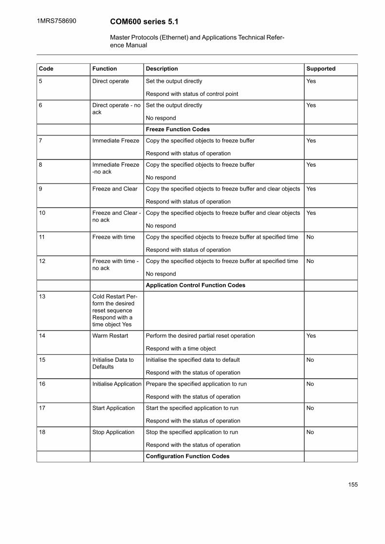
SupportedDescriptionFunctionCode
YesSet the output directly
Respond with status of control point
Direct operate5
YesSet the output directly
No respond
Direct operate - noack
6
Freeze Function Codes
YesCopy the specified objects to freeze buffer
Respond with status of operation
Immediate Freeze7
YesCopy the specified objects to freeze buffer
No respond
Immediate Freeze-no ack
8
YesCopy the specified objects to freeze buffer and clear objects
Respond with status of operation
Freeze and Clear9
YesCopy the specified objects to freeze buffer and clear objects
No respond
Freeze and Clear -no ack
10
NoCopy the specified objects to freeze buffer at specified time
Respond with status of operation
Freeze with time11
NoCopy the specified objects to freeze buffer at specified time
No respond
Freeze with time -no ack
12
Application Control Function Codes
Cold Restart Per-form the desiredreset sequenceRespond with atime object Yes
13
YesPerform the desired partial reset operation
Respond with a time object
Warm Restart14
NoInitialise the specified data to default
Respond with the status of operation
Initialise Data toDefaults
15
NoPrepare the specified application to run
Respond with the status of operation
Initialise Application16
NoStart the specified application to run
Respond with the status of operation
Start Application17
NoStop the specified application to run
Respond with the status of operation
Stop Application18
Configuration Function Codes
155
COM600 series 5.11MRS758690
Master Protocols (Ethernet) and Applications Technical Refer-ence Manual

SupportedDescriptionFunctionCode
NoSave the configuration
Respond with status of operation
Save configuration19
NoEnable Unsolicited Messages
Respond with status of operation
Enable UnsolicitedMessages
20
NoDisable Unsolicited Messages
Respond with status of operation
Disable UnsolicitedMessages
21
NoAssign specified objects to a class
Respond with status of operation
Assign Class22
Time Synchronization Function Codes
YesPerform propagation delay measurementDelay Measure-ment
23
YesUsed in a network application to allow the Master station andthe Out station to record their time at the same instant
Record current time24
Response Function Codes
YesMessage fragment confirmationConfirm0
YesResponse to requested messageResponse129
YesSpontaneous message without requestUnsolicited Mes-sage
130
Level of Implementation
DNP has three subset levels, each of which includes a specific subset of DNP messagetypes and functionality. In COM600 the DNP protocol has been implemented accordingto the Subset Level 2 of the protocol as presented in Table A2-3.
Table A2-3 Data object types and variations supportedQualifier codeof Responsemessage
Function codeof Responsemessage
Qualifier codeof Requestmessage
Function codeof Requestmessage
DescriptionVariationData objecttype
61Binary input, allvariations
01
0,1129,130Binary input11
0,1129,130Binary input withstatus
21
6,7,81Binary inputchange, all vari-ations
02
156
1MRS758690COM600 series 5.1
Master Protocols (Ethernet) and Applications Technical Refer-ence Manual

Qualifier codeof Responsemessage
Function codeof Responsemessage
Qualifier codeof Requestmessage
Function codeof Requestmessage
DescriptionVariationData objecttype
17,28129,1306,7,81Binary inputchange withouttime
12
17,28129,1306,7,81Binary inputchange withtime
22
17,28129,1306,7,81Binary inputchange with rel-ative time
32
61Binary output, allvariations
010
0,1129,130Binary outputstatus
110
echo12917,283,4,5,6Control relayoutput block
112
17,281,7,8,9,10Binary counter,all variations
020
0,1129,13032-bit binarycounter
120
0,1129,13016-bit binarycounter
220
0,1129,13032-bit deltacounter
320
0,1129,13016-bit deltacounter
420
0,1129,13032-bit binarycounter withoutflag
520
0,1129,13016-bit binarycounter withoutflag
620
0,1129,13032-bit deltacounter withoutflag
720
0,1129,13016-bit deltacounter withoutflag
820
61Frozen counter,all variations
021
0,1129,13032-bit frozencounter
121
157
COM600 series 5.11MRS758690
Master Protocols (Ethernet) and Applications Technical Refer-ence Manual

Qualifier codeof Responsemessage
Function codeof Responsemessage
Qualifier codeof Requestmessage
Function codeof Requestmessage
DescriptionVariationData objecttype
0,1129,13016-bit frozencounter
221
0,1129,13032-bit frozencounter withoutflag
921
0,1129,13016-bit frozencounter withoutflag
1021
6,7,81Counter changeevent, all vari-ations
022
17,28129,13032-bit counterchange eventwithout time
122
17,28129,13016-bit counterchange eventwithout time
222
61Analog input, allvariations
030
0,1129,13032-bit analoginput
130
0,1129,13016-bit analoginput
230
0,1129,13032-bit analoginput withoutflag
330
0,1129,1300,1,6116-bit analoginput withoutflag
430
6,7,81Analog changeevent, all vari-ations
032
17,28129,13032-bit analogchange eventwithout time
132
17,28129,13016-bit analogchange eventwithout time
232
0,1129,13061Analog outputstatus, all vari-ations
040
16-bit analogoutput status
240
158
1MRS758690COM600 series 5.1
Master Protocols (Ethernet) and Applications Technical Refer-ence Manual

Qualifier codeof Responsemessage
Function codeof Responsemessage
Qualifier codeof Requestmessage
Function codeof Requestmessage
DescriptionVariationData objecttype
echo12917,283,4,5,616-bit analogoutput block
241
72Time and date150
7129,130Time and dateCTO
151
7129,130Unsynchronisedtime and dateCTO
251
7129Time and datecoarse
152
7129Time delay fine252
61Class 0 data160
6,7,81Class 1 data260
6,7,81Class 2 data360
6,7,81Class 3 data460
02Internal indica-tions
180
13No object
23No object
• Obj. is the data object type.• Var. is the variation.• Func. is the function code of the message.• Qual. is the qualifier code of the message in hexadecimal.• Echo means that the response is the request mirrored.
TCP/UDP additions for LAN/WAN network
DNP LAN/WAN OPC Server uses the default IP address provided by the operatingsystem. A created DNP Master line reserves a port number 2501+linenumber for itsinternal use.
In TCP/IP mode (connection-oriented), the connection is established to the port 20000(default) of the slave device. Only one connection to each master station is establishedat the same time. The IP address of the master is configured with the Internet Addressproperty of the IED object.
The remote port number can be configured by using an option in the IED propertyInternet Address.
159
COM600 series 5.11MRS758690
Master Protocols (Ethernet) and Applications Technical Refer-ence Manual

In UDP/IP mode (connectionless) all data is sent and received through the port 20000.The slave device must receive messages from this port only. All messages that are sentby the slave device must be sent to this port of the master. The IP address of the slaveis configured with the Internet Address property of the IED object.
160
1MRS758690COM600 series 5.1
Master Protocols (Ethernet) and Applications Technical Refer-ence Manual

Index
AABBCommandBitmask
mapping ......................................................................................................... 30Analog set point (APC) ........................................................................................ 54Analogue set point (APC) .................................................................................. 113
IEC 61850 data modeling .............................................................................. 125Analogue setting (ASG)
common data class ......................................................................................... 57Analogue value
configuration .................................................................................................. 27float values ..................................................................................................... 26
attributeschannel .......................................................................................................... 99client .............................................................................................................. 98device .......................................................................................................... 100Modbus channel ........................................................................................... 127Modbus device ............................................................................................. 128server .......................................................................................................... 126
BBinary controlled step position information (BSC)
common data class ......................................................................................... 50IEC 61850 data modeling ................................................................. 96, 113, 125
Binary counter reading (BCR)common data class ......................................................................................... 36IEC 61850 data modeling ......................................................................... 92, 117
CCancel ............................................................................................................... 79channel
attributes ........................................................................................................ 99common data class
Analogue setting (ASG) ................................................................................... 57Binary controlled step position information (BSC) .............................................. 50Binary counter reading (BCR) .......................................................................... 36Complex measured value (CMV) ..................................................................... 38Controllable double point (DPC) ............................................................... 44, 123Controllable integer status (INC) ...................................................................... 47Controllable single point (SPC) ........................................................................ 42Delta (DEL) .................................................................................................... 40Device name plate (DPL) ................................................................................ 59Directional protection activation information (ACD) ............................................ 34Double point status (DPS) ............................................................................... 31
161
COM600 series 5.11MRS758690
Master Protocols (Ethernet) and Applications Technical Refer-ence Manual

Integer controlled step position information (ISC) .............................................. 52Integer status (INS) ......................................................................................... 32Integer status setting (ING) .............................................................................. 56Logical node name plate (LPL) ........................................................................ 59Measured value (MV) ...................................................................................... 37Protection activation information (ACT) ............................................................ 33Sampled value (SAV) ...................................................................................... 39Security violation counter (SEC) ...................................................................... 35Setting curve (CURVE) ................................................................................... 58Single point setting (SPG) ............................................................................... 56Single point status (SPS) ................................................................................ 31WYE .............................................................................................................. 40
Complex measured value (CMV)common data class ......................................................................................... 38IEC 61850 data modeling ......................................................................... 93, 106
configurationAnalogue value ............................................................................................... 27
conformance statementACSI basic ..................................................................................................... 82ACSI models .................................................................................................. 82ACSI service .................................................................................................. 84general .......................................................................................................... 81
Controllable double point (DPC)common data class ................................................................................. 44, 123IEC 61850 data modeling .............................................................................. 112
Controllable Enumerated Status (ENC) ............................................................... 112Controllable integer status (INC)
common data class ......................................................................................... 47IEC 61850 data modeling ................................................................. 95, 112, 124
Controllable single point (SPC)common data class ......................................................................................... 42IEC 61850 data modeling ......................................................................... 94, 111
Ddata object
properties ..................................................................................................... 134DeleteFile ........................................................................................................... 79Delta (DEL)
common data class ......................................................................................... 40IEC 61850 data modeling ........................................................................ 94, 110
DetailedQualitymapping ......................................................................................................... 26
deviceattributes ...................................................................................................... 100
Device name plate (DPL)common data class ......................................................................................... 59IEC 61850 data modeling .............................................................................. 118
Directional protection activation information (ACD)common data class ......................................................................................... 34IEC 61850 data modeling ......................................................................... 91, 104
162
1MRS758690COM600 series 5.1
Master Protocols (Ethernet) and Applications Technical Refer-ence Manual

DNP 3.0 OPC Serverfeatures ......................................................................................................... 20
Double point status (DPS)common data class ......................................................................................... 31IEC 61850 data modeling .............................................................................. 116IEC61860 data modeling ......................................................................... 90, 103
EEnumerated Status (ENS)
...................................................................................................................... 33Enumerated status (ENS) .................................................................................. 103External OPC Server
features ......................................................................................................... 22
Ffeatures
IEC 60870-5-104 OPC Server ......................................................................... 20SNTP ............................................................................................................. 23
File transferattributes ........................................................................................................ 74service codes ................................................................................................. 80services ......................................................................................................... 75
functional overview ............................................................................................. 17
GGetFile ............................................................................................................... 76GetFileAttributeValues ........................................................................................ 76GetFileAttributeValuesEx ..................................................................................... 77
IIEC 60870-5-104 OPC Server
features ......................................................................................................... 20IEC 61850
device attributes ............................................................................................. 66logical device attributes ................................................................................... 73subnetwork attributes ...................................................................................... 63
IEC 61850 data modelingAnalogue set point (APC) .............................................................................. 125Binary controlled step position information (BSC) ..................................... 113, 125Binary counter reading (BCR) ................................................................... 92, 117Complex measured value (CMV) .............................................................. 93, 106Controllable double point (DPC) ..................................................................... 112Controllable integer status (INC) ....................................................... 95, 112, 124Controllable single point (SPC) ................................................................. 94, 111Delta (DEL) ............................................................................................. 94, 110Device name plate (DPL) ............................................................................... 118
163
COM600 series 5.11MRS758690
Master Protocols (Ethernet) and Applications Technical Refer-ence Manual

Directional protection activation information (ACD) .................................... 91, 104Double point status (DPS) ................................................................ 90, 103, 116Integer controlled step position information (ISC) ..................................... 113, 125Integer status (INS) .......................................................................... 90, 103, 116Logical node name plate (LPL) ....................................................................... 118Measured value (MV) ....................................................................... 92, 106, 118Protection activation information (ACT) .............................................. 91, 104, 117Single point status (SPS) .................................................................. 89, 102, 115WYE ............................................................................................... 93, 107, 119
IEC 61850 OPC Serverfeatures ......................................................................................................... 19
IEC 61850 quality ............................................................................................... 24IED
properties ..................................................................................................... 132Integer controlled step position information (ISC)
common data class ......................................................................................... 52IEC 61850 data modeling ....................................................................... 113, 125
Integer status (INS)common data class ......................................................................................... 32IEC 61850 data modeling ......................................................................... 90, 103
Integer status setting (ING)common data class ......................................................................................... 56
LLogical node name plate (LPL)
common data class ......................................................................................... 59IEC 61850 data modeling .............................................................................. 118
Mmapping
ABBCommandBitmask .................................................................................... 30DetailedQuality ............................................................................................... 26originator ........................................................................................................ 28pulse configuration .......................................................................................... 28quality value ................................................................................................... 25range configuration ......................................................................................... 27step position with transient indication ............................................................... 28unit ................................................................................................................ 29vector ............................................................................................................ 29
Measured value (MV)common data class ......................................................................................... 37IEC 61850 data modeling ................................................................. 92, 106, 118
Modbus channelattributes ...................................................................................................... 127
Modbus deviceattributes ...................................................................................................... 128
Modbus OPC Serverfeatures ......................................................................................................... 21
164
1MRS758690COM600 series 5.1
Master Protocols (Ethernet) and Applications Technical Refer-ence Manual

OOPC Server
redundant ..................................................................................................... 131originator
mapping ......................................................................................................... 28Output attribute ............................................................................................. 77–78
PProtection activation information (ACT)
common data class ......................................................................................... 33IEC 61850 data modeling ................................................................. 91, 104, 117
pulse configurationmapping ......................................................................................................... 28
Qquality value
mapping ......................................................................................................... 25
Rrange configuration
mapping ......................................................................................................... 27RenameFile ........................................................................................................ 78
SSampled value (SAV)
common data class ......................................................................................... 39Security violation counter (SEC)
common data class ......................................................................................... 35Sequence (SEQ)
common data class ......................................................................................... 41server
attributes ................................................................................................ 98, 126Server attributes ................................................................................................. 61SetFile ............................................................................................................... 79Setting curve (CURVE)
common data class ......................................................................................... 58Single point setting (SPG)
common data class ......................................................................................... 56Single point status (SPS)
common data class ......................................................................................... 31IEC 61850 data modeling ................................................................. 89, 102, 115
SNTPfeatures ......................................................................................................... 23
step position with transient indication
165
COM600 series 5.11MRS758690
Master Protocols (Ethernet) and Applications Technical Refer-ence Manual

mapping ......................................................................................................... 28subnet
properties ..................................................................................................... 131
Ttimestamp .......................................................................................................... 29Transparent XSAT attribute ................................................................................. 70
Uunit
mapping ......................................................................................................... 29
Vvector
mapping ......................................................................................................... 29
WWYE
common data class ......................................................................................... 40IEC 61850 data modeling ................................................................. 93, 107, 119
166
1MRS758690COM600 series 5.1
Master Protocols (Ethernet) and Applications Technical Refer-ence Manual


—ABB Distribution SolutionsDistribution AutomationP.O. Box 699FI-65101 Vaasa, FinlandPhone: +358 10 22 11
ABB Distribution Automation4300 Coral Ridge DriveCoral Springs, Florida 33065Phone: +1 954 752 6700
www.abb.com/mediumvoltagewww.abb.com/substationautomation
1MRS758690 B/12.04.2018 © Copyright 2018 ABB. All rights reserved.Specifications subject to change without notice.