colorado department of transportation … · · 2010-06-01colorado department of transportation...
TRANSCRIPT

COLORADO DEPARTMENT OF TRANSPORTATIONSTAFF BRIDGE
BRIDGE RATING MANUAL
Section: 10Effective: July 1, 2002Supersedes: July 1, 1995
SECTION 10 – STEEL BRIDGES
10-1 INTRODUCTION TO RATING STEEL BRIDGES
This section together with Section 1, presents the policies andguidelines for rating steel girders. Policies are covered in subsection10-2, while supporting guidelines are presented in subsections 10-2, 3,and 4.
The types of girders covered by this section are:
CI Concrete on I-BeamCIC Concrete on I-Beam ContinuousCIK Concrete on I-Beam CompositeCICK Concrete on I-Beam Continuous and CompositeSBG Steel Box GirderSBGC Steel Box Girder ContinuousSDG Steel Deck GirderSDGC Steel Deck Girder ContinuousSSD Steel Stringer - Concrete DeckSSE Steel Stringer - Earth FilledSSM Steel Stringer - Metal Plank FloorSSMC Steel Stringer Continuous - Metal Plank FloorSSS Steel Stringer - Timber FloorSSSC Steel Stringer Continuous - Timber FloorSTG Steel Through GirderWG Welded GirderWGC Welded Girder ContinuousWGK Welded Girder CompositeWGCK Welded Girder Continuous and Composite
10-2 POLICIES AND GUIDELINES FOR RATING STEEL BRIDGES
I. General
A. All steel girders (except for girders in Truss Bridges) shall berated by the VIRTIS program or one acceptable to the CDOT BridgeBranch.
B. Steel girders with considerable stress/strain effects due tohorizontal curvature, skew, temperature, or other influences shallbe modeled as simple, straight beams on pin or roller supports.The VIRTIS output results can then be supplemented with handcalculations to consider any of these significant influences, asnecessary. Also, when appropriate, steel girders having or lackinghorizontal curvature effects and depending on the type of girderto be analyzed, DESCUS I or DESCUS II may also be used to performthe rating.
C. All steel bridges shall be rated by the load factor method.
D. Use the minimum design yield strength value (Fy) and the minimumcompressive strength of concrete (F'c) from plans.

July 1, 2002 Section 10 Page 2 of 55
E. For SSE, SSM and SSS structure types, it is acceptable todisregard AASHTO's allowable stress reduction formula forunsupported compression flanges. If the condition of the girderindicates that full yield strength should not be used, the ratingstresses should be reduced as appropriate.
F. Steel box girder template has not been incorporated in the currentversion of Virtis 4.0.4. However, steel box girders can be ratedusing ½ the single-girder parameters in the analysis. The liveload distribution factor and the dead load shall be adjustedaccordingly.
II. Girders Requiring Rating
A. Interior Girders - A rating is required for the critical interiorgirder. More than one interior girder may require an analysis dueto variation in span length, girder size, girder spacing,differences in loads or moments, grade of structural steel, etc.
B. Exterior Girders - An exterior girder shall be rated under thefollowing guidelines.
1. When the section used for an exterior girder is different thanthe section used for an interior girder.
2. When the overhang is greater than S/2.
3. When the plans indicate that the curb and floor slab werepoured monolithically, the live load distribution factor for theexterior girder should be calculated and compared to the liveload distribution factor (LLDF) for the interior girders. If theLLDF for the exterior girder is equal to or greater than 75% ofthe LLDF for the interior girders, the exterior girder shall berated.
4. When the rater determines the rating would be advantageous inanalyzing the overall condition of a structure.
III. Calculations
A. A set of calculations, separate from computer output shall beprepared and submitted with each rating. These calculations shallinclude derivations for dead loads, derivations for live loaddistribution factors, and any other calculations or assumptionsused for rating.
B. Dead Loads
1. The final sum of all the individual weight components for deadload calculations may be rounded up to the next 5 pounds.
2. Dead loads applied after a cast-in-place concrete deck hascured shall be distributed equally to all girders and, whenapplicable, treated as composite dead loads. Examples includeasphalt, curbs, sidewalks, railing, etc.

July 1, 2002 Section 10 Page 3 of 55
3. Use 5 psf for the unit weight of permanent steel bridge deckforms.
4. Dead loads applied before a cast-in-place concrete deck hascured shall be distributed to the applicable individual supportinggirders and treated as non-composite loads. Examples of this typeof dead load are deck slabs, girders, stiffeners, splices anddiaphragms. The weight of diaphragms may be treated as point loadsor as an equivalent uniform dead load for the span underconsideration.
EXAMPLE: For two diaphragms (P) at 1/3 points
(PL)/3 = M = (wL x L)/8
Equivalent uniform load . . . w = (8P)/3L
5. The method of applying dead loads due to utilities is left tothe rater's discretion.
IV. Rating Reporting/Package Requirements
The rater and checker shall complete the rating documentation asdescribed in Section 1 of this manual. Additionally, yield strength(Fy) of structural steel used in the analysis and any variation fromthe original design assumptions shall be added to the Rating SummarySheet. The rating package requirements shall be per Section 1-13 ofthis manual and as amended herein:
Consultant designed projects – Before finalizing the rating package andwhen VIRTIS is used as the analysis tool, the Rater shall verify withthe Staff Bridge Rating Coordinator that the version number of theprogram being used is identical to CDOT’S version number. Data filescreated using a lower version of the program shall be rejected. It isrequired for the CDOT data archive, since the data base managementfeature inside the program would not work satisfactorily. After theanalysis is completed, the rater shall save the data file. When savingis finalized, the rater shall export the data file in *.bbd format(i.e., F-17-IE.bbd format; bbd = BRIDGEWare Bridge Data File) on anIBM- compatible 3.5” PC Disk for delivery with the rating package.Also, the version number used during analysis shall be written on thediskette label. This ensures proper importation of bridge data archiveby Staff Bridge at a later date.

July 1, 2002 Section 10 Page 4 of 55
10-3 GUIDELINES FOR USING THE VIRTIS RATING PROGRAM
The VIRTIS computer program performs the analysis and rating of simplespan and multi-span steel girder bridges. It uses the BRASS ASD or theBRASS LFD engine for analysis. This program was developed in accordancewith the AASHTO STANDARD SPECIFICATIONS, 16TH EDITION AND THE AASHTOMANUAL FOR CONDITION EVALUATION OF BRIDGES.
A maximum of thirteen (13) spans can be modeled using the program.Linear or parabolic girder web depth variation over the length of adefined cross-section can be modeled using Virtis. When a structuremodel is finalized, it can be rated using the ASD or the LFD method.The LRFD rating module is currently being developed and will beavailable in the future. When a structure model is being generated andbefore any analysis can be performed, it is recommended that Virtisusers save the data to memory periodically. This can be accomplished byusing the File and Save feature of this program.
The library explorer can be used to save commonly used items (beamshapes, non standard vehicles, materials, appurtenances etc.) and thiseliminates the need for all users to define the same items repeatedlythroughout the program. Once a new girder shape is defined or copiedfrom the library, Virtis automatically computes the required sectionproperties and beam constants.
Dead load from the girder self weight, deck slab and appurtenances(i.e. rails, median barrier etc.) are calculated automatically by theprogram. Dead load from the haunch, wearing surface and stiffenerweight (for steel bridges) is defined by the user. For a detaileddescription of the girder loads, refer to the Opis/Virtis Help Menuindex item - dead loads. When a structure is being modeled, the helpmenu can be activated by using the F1 key if the user requiresclarification on a particular item in the GUI window.
In the Live Load Distribution Factor window, when the compute button isused to calculate the DF’s automatically by the program, Virtis usersshall verify that these numbers are accurate and matches theircalculated numbers.
All Colorado BT girder shapes, W-beam shapes, the Colorado permitvehicle, the Colorado posting trucks, and the Interstate posting truckshave been added to the Virtis library explorer and may be copied by theuser. The Staff Bridge Rating Coordinator shall be responsible forupdating existing information or adding new information (i.e. beamshapes, vehicles, etc.) to the library explorer.
The configuration browser provides access to the configuration featuresof Virtis. It may be employed to provide specific access privileges,i.e. read, write, delete etc., to the users. This feature is extremelypowerful, since Virtis/Opis uses and shares the bridge data from onecommon source. Therefore, it is required that users of this programcreate a folder from the bridge explorer window (EXAMPLE: MY FOLDER ORYOUR LAST NAME) before creating the model for a new structure.

July 1, 2002 Section 10 Page 5 of 55
10-4 RATING STEEL BRIDGES WITHOUT PLANS
It is possible that the only information a rater may have to rate anold steel bridge is field measurements of the members and thedirections of the AASHTO MANUAL FOR CONDITION EVALUATION OF BRIDGES1994, Second Edition. A convenient source of beam information is thebook titled “Historical Record-Dimensions and Properties-Iron and SteelBeams 1873 to 1952”, published by the American Institute of SteelConstruction (AISC). This book can help the rater determine theapproximate year the beams were rolled. The rater can then determinethe section properties and the allowable stresses to be used to ratethe steel beams.

July 1, 2002 Section 10 Page 6 of 55
10-5 STEEL GIRDER BRIDGE RATING EXAMPLE
One example is presented in this section. Structure N-17-BP is a two(2) span continuous composite welded girder bridge with a skew of 0°degrees. Note that the girder web varies linearly near the pier. Forsimplicity, only the interior girder has been modeled for thisstructure.
One curved welded girder example using Descus-I will be presented at alater date.
Also, one curved welded box girder example using Descus-II will bepresented at a later date.

July 1, 2002 Section 10 Page 7 of 55
Slab Rating Program Input, Structure No. N-17-BP
Effective Span Length: Per AASHTO Article 3.24.1.2(b) Clear distance between flanges + 1/2 flange width = (105-12)+1/2(12)=93.0”
=8.25’
July 1, 2002 Section 10 Page 8 of 55
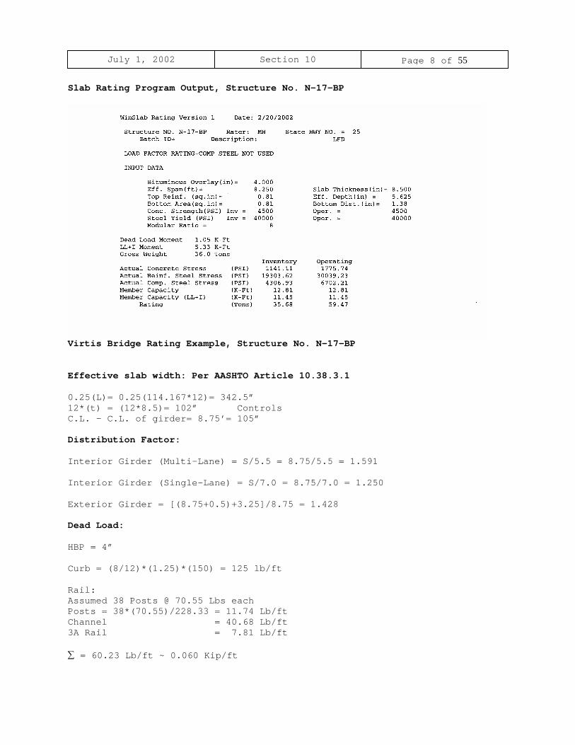
Slab Rating Program Output, Structure No. N-17-BP
Virtis Bridge Rating Example, Structure No. N-17-BP
Effective slab width: Per AASHTO Article 10.38.3.1 0.25(L)= 0.25(114.167*12)= 342.5”12*(t) = (12*8.5)= 102” ControlsC.L. - C.L. of girder= 8.75’= 105”
Distribution Factor:
Interior Girder (Multi-Lane) = S/5.5 = 8.75/5.5 = 1.591 Interior Girder (Single-Lane) = S/7.0 = 8.75/7.0 = 1.250 Exterior Girder = [(8.75+0.5)+3.25]/8.75 = 1.428
Dead Load: HBP = 4” Curb = (8/12)*(1.25)*(150) = 125 lb/ft Rail:Assumed 38 Posts @ 70.55 Lbs eachPosts = 38*(70.55)/228.33 = 11.74 Lb/ftChannel = 40.68 Lb/ft3A Rail = 7.81 Lb/ft
∑ = 60.23 Lb/ft ~ 0.060 Kip/ft

July 1, 2002 Section 10 Page 9 of 55
Interior (D-2 on plan sheet) Diaphragms:
Angles L3x3x5/16 @ 6.1 lb/ft Length = 2(8.75)+2(5.71)=28.92’Weight = (28.92)*(6.1) = 176.41 LbsStiffener Plate 5x5/16x4.5’Weight = 2(5.32)(4.5) = 47.88 Lbs∑ = 224.29 Lbs ~ 0.225 Kips Pier (D-2 on plan sheet) Diaphragm: Angles L3x3x5/16 @ 6.1 lb/ft Length = 2(8.75)+2(5.71)=28.92’Weight = (28.92)*(6.1) = 176.41 LbsStiffener Plate 9x1x7.135’Weight = 2(30.625)(7.135) = 437.04 Lbs∑ = 613.40 Lbs ~ 0.614 Kips End (D-1 on plan sheet) Diaphragms: Angles L3.5x3.5x5/16 @ 7.2 lb/ft Length = 2(9.839)=19.68’Weight = (19.68)*(7.2) = 141.70 LbsStiffener Plate 6.5x5/8x4.5’Weight = 2(13.817)(4.5) = 124.3 Lbs∑ = 266.0 Lbs ~ 0.266 Kips Intermediate Stiffeners: Assumed length = depth of web = 54”; Neglect longer stiffeners in girder taperStiffener Plate 5x5/16x4.5’ @ 5.32Lbs/ft = 23.94 Lbs each21 Stiffeners/Span = 21*(23.94)/114.167 = 4.4 Lbs/ft Longitudinal Stiffeners: Stiffener Plate 4.5x5/16 = 4.79 Lbs/ftStiffener Plate 3.5x5/16 = 3.72 Lbs/ftAverage Weight = 4.2 Lbs/ft∑ Transverse + Longitudinal Stiffeners = 4.4+4.2 = 8.6 Lbs/ft ~ 0.009 Kip/ft

July 1, 2002 Section 10 Page 10 of 55
July 1, 2002 Section 10 Page 11 of 55
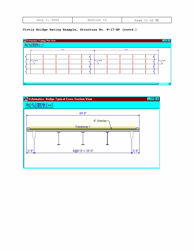
Virtis Bridge Rating Example, Structure No. N-17-BP (contd.)

July 1, 2002 Section 10 Page 12 of 55
From the bridge explorer, create a new bridge and enter the followinginformation.
Click OK. This saves the data to memory and closes the window.
NOTE: Since Virtis uses a common/shared database, it is required that usersof this program create a folder from the bridge explorer window(EXAMPLE: MY FOLDER OR YOUR LAST NAME) before creating the model for anew structure.
July 1, 2002 Section 10 Page 13 of 55
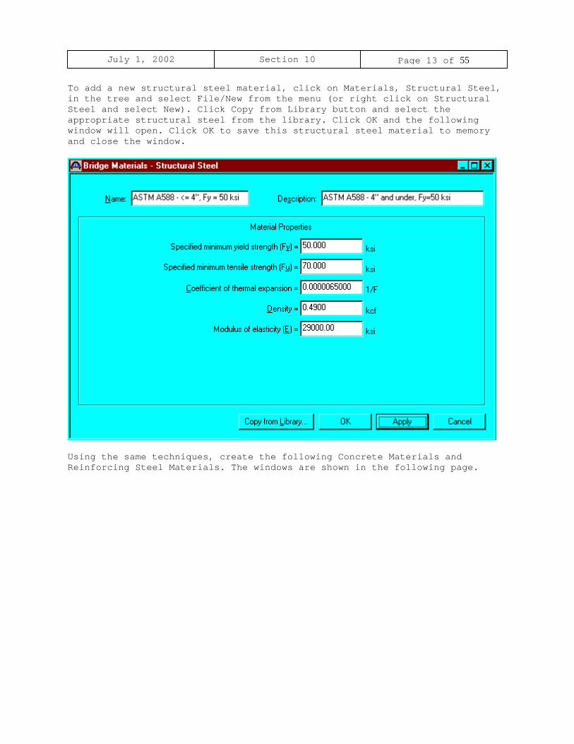
To add a new structural steel material, click on Materials, Structural Steel,in the tree and select File/New from the menu (or right click on StructuralSteel and select New). Click Copy from Library button and select theappropriate structural steel from the library. Click OK and the followingwindow will open. Click OK to save this structural steel material to memoryand close the window.
Using the same techniques, create the following Concrete Materials andReinforcing Steel Materials. The windows are shown in the following page.

July 1, 2002 Section 10 Page 14 of 55

July 1, 2002 Section 10 Page 15 of 55
To enter the appurtenances to be used within the bridge, expand the explorertree labeled Appurtenances. Right mouse click on Parapet in the tree, andselect New. Fill in the parapet properties as required. Click OK to save thedata to memory and close the window.
July 1, 2002 Section 10 Page 16 of 55
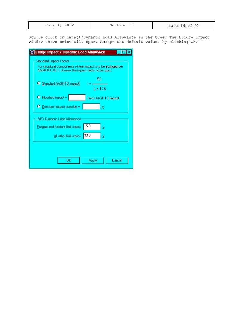
Double click on Impact/Dynamic Load Allowance in the tree. The Bridge Impactwindow shown below will open. Accept the default values by clicking OK.

July 1, 2002 Section 10 Page 17 of 55
Click on Factors, right mouse click on LFD and select New. The LFD-Factorswindow will open. Click the Copy from Library button and select the 1996AASHTO Standard Specifications from the library. Click Apply and then OK tosave data to memory and close the window.

July 1, 2002 Section 10 Page 18 of 55
Double click on SUPERSTRUCTURE DEFINITION (or click on SUPERSTRUCTUREDEFINITION and select File/New from the menu or right mouse click onSUPERSTRUCTURE DEFINITION and select New from the popup menu) to create a newstructure definition. The following dialog box will appear.

July 1, 2002 Section 10 Page 19 of 55
Select Girder System and the following Structure Definition window will open.Enter the appropriate data as shown below. Press F1 while on this tab to viewthe help topic describing the use of this information.
July 1, 2002 Section 10 Page 20 of 55
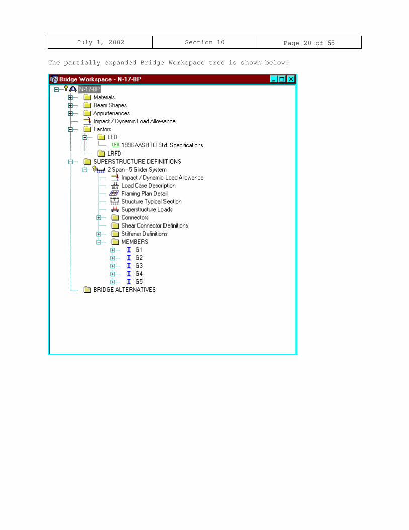
The partially expanded Bridge Workspace tree is shown below:

July 1, 2002 Section 10 Page 21 of 55
The Analysis tab in the Girder System Superstructure Definition window isused to override system default factors. Since default factors are used here,click OK to save the data to memory and close the window.

July 1, 2002 Section 10 Page 22 of 55
Click Load Case Description to define the dead load cases. The load types arepresented in a single row separated by a comma. The first type applies to theLFD design and the second type applies to the LRFD design and it correspondswith the load types presented in the AASHTO Specifications. The completedLoad Case Description window is shown below.
July 1, 2002 Section 10 Page 23 of 55
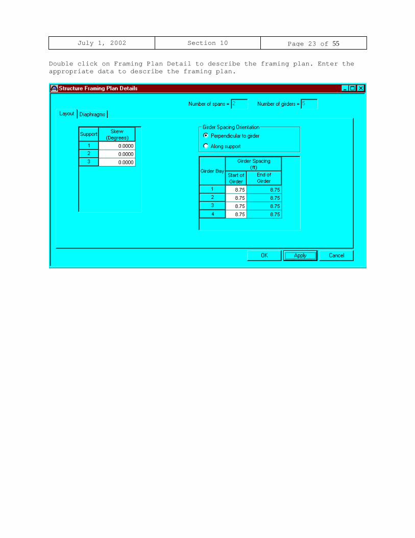
Double click on Framing Plan Detail to describe the framing plan. Enter theappropriate data to describe the framing plan.

July 1, 2002 Section 10 Page 24 of 55
Switch to the Diaphragms tab to enter diaphragm spacing. Enter the followingdiaphragms data for Girder Bay 1:
Click the Copy Bay To button to copy the diaphragms entered for Bay to theother bays. The following dialog box will appear. Click Apply to copy thediaphragms to girder bay 2. Repeat the same techniques for girder bay 3 and4.
Select OK to close Structure Framing Plan Details window.

July 1, 2002 Section 10 Page 25 of 55
Double click on Structure Typical Section in the Bridge Workspace tree todefine the structure typical section. Input the data describing the typicalsection as shown below.

July 1, 2002 Section 10 Page 26 of 55
The Deck (Cont’d) tab is used to enter information about the deck concreteand thickness. The material to be used for the deck concrete is selected fromthe list of bridge materials described previously.
July 1, 2002 Section 10 Page 27 of 55
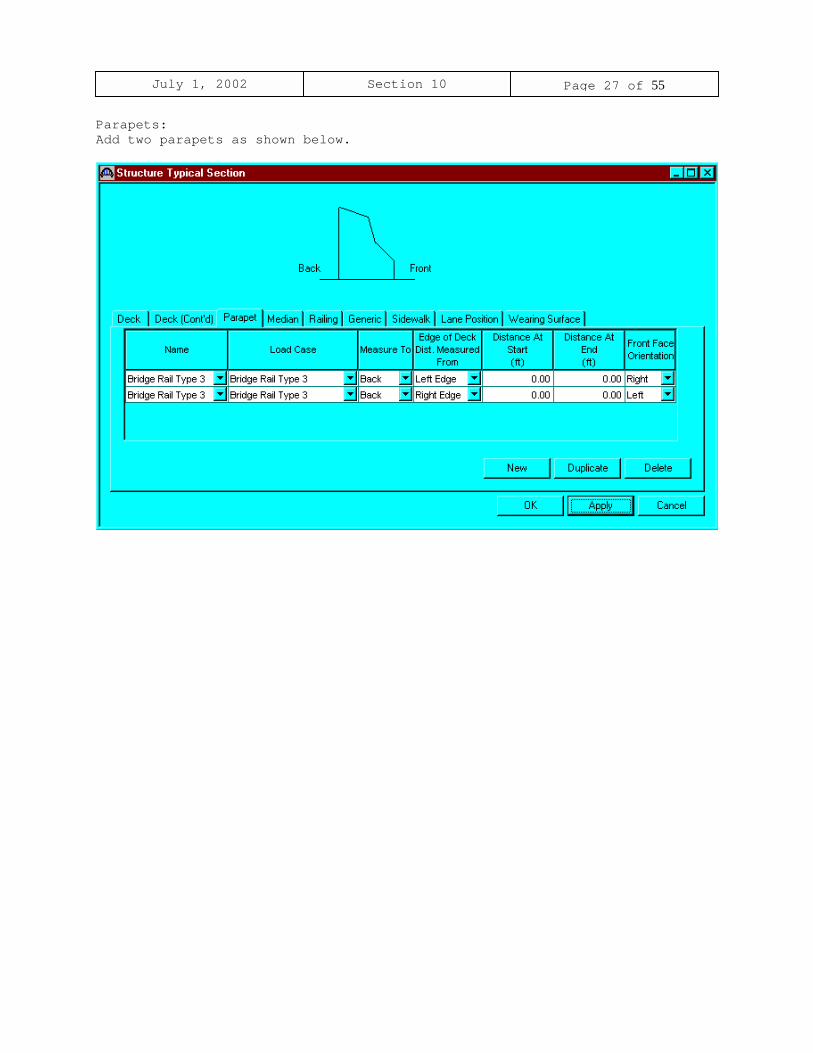
Parapets:Add two parapets as shown below.

July 1, 2002 Section 10 Page 28 of 55
Lane Positions:Select the lane position tab and use the Compute… button to compute the lanepositions. A dialog showing the results of the computation opens. Click Applyto accept the computed values. The Lane Position tab is populated as shownbelow.

July 1, 2002 Section 10 Page 29 of 55
Enter the following wearing surface information on the Wearing Surface tab.

July 1, 2002 Section 10 Page 30 of 55
Double click on the Structure Loads tree item to define the DL Distribution.Select the required DL Distribution. Click OK to save this information tomemory and close the window.

July 1, 2002 Section 10 Page 31 of 55
Expand the Stiffener Definitions tree item and double click on Transverse.Define the stiffener as shown below. Click OK to save to memory and close thewindow.

July 1, 2002 Section 10 Page 32 of 55
Similarly, define bearing stiffeners by double clicking on Bearing in thetree. Click OK to save to memory and close the window.

July 1, 2002 Section 10 Page 33 of 55

July 1, 2002 Section 10 Page 34 of 55
Describing a member:The member window shows the data that was generated when the structuredefinition was created. No changes are required at this time. The firstMember Alternative that we create will automatically be assigned as theExisting and Current Member alternative for this member.
July 1, 2002 Section 10 Page 35 of 55
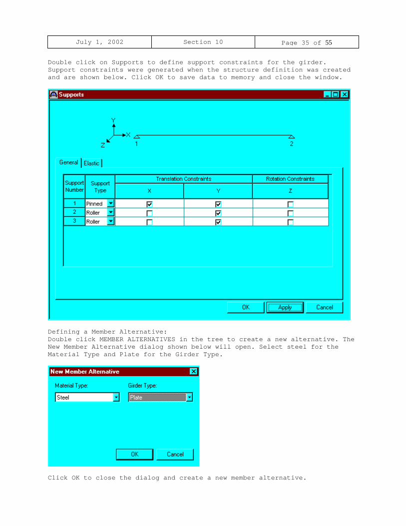
Double click on Supports to define support constraints for the girder.Support constraints were generated when the structure definition was createdand are shown below. Click OK to save data to memory and close the window.
Defining a Member Alternative:Double click MEMBER ALTERNATIVES in the tree to create a new alternative. TheNew Member Alternative dialog shown below will open. Select steel for theMaterial Type and Plate for the Girder Type.
Click OK to close the dialog and create a new member alternative.

July 1, 2002 Section 10 Page 36 of 55
July 1, 2002 Section 10 Page 37 of 55
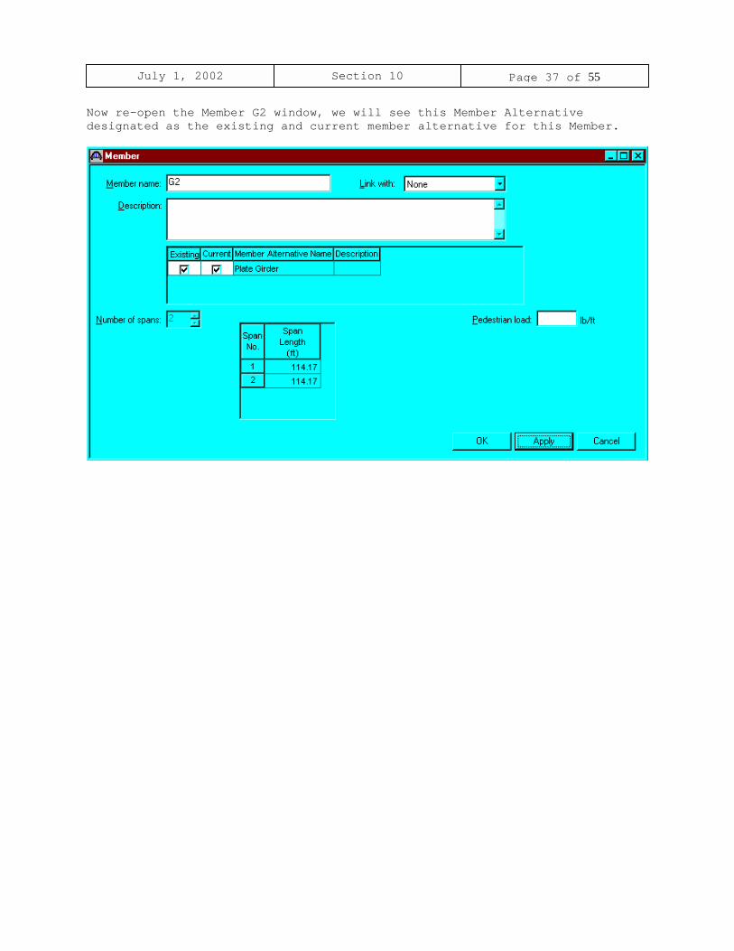
Now re-open the Member G2 window, we will see this Member Alternativedesignated as the existing and current member alternative for this Member.

July 1, 2002 Section 10 Page 38 of 55
Double click on Live Load Distribution to enter live load distributionfactors. Click the Compute from Typical Section button to compute the liveload distribution factors. The distribution factors are computed based on theAASHTO Specifications, Articles 3.23. Click Apply and then OK to save data tomemory and close the window.

July 1, 2002 Section 10 Page 39 of 55
Double click on Girder Profile in the tree to describe the girder profile.The window is shown below with the data describing the web.

July 1, 2002 Section 10 Page 40 of 55
Describe the flanges as shown below.

July 1, 2002 Section 10 Page 41 of 55
Double click on Deck Profile and enter data describing the structuralproperties of the deck. The deck concrete and reinforcement windows are shownbelow.
July 1, 2002 Section 10 Page 42 of 55
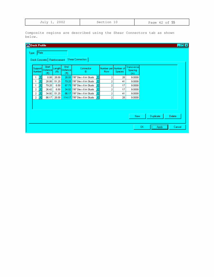
Composite regions are described using the Shear Connectors tab as shownbelow.

July 1, 2002 Section 10 Page 43 of 55
Double click on Haunch Profile in the tree to define the haunch profile.Check the box ‘embedded flange’ if the top flanges of the girder is embeddedin the concrete haunch.

July 1, 2002 Section 10 Page 44 of 55
Regions where the hardened concrete deck slab is considered to providelateral support for the top flange are defined using the Lateral Supportwindow.

July 1, 2002 Section 10 Page 45 of 55
Define stiffener locations using the Stiffener Ranges window shown below.
July 1, 2002 Section 10 Page 46 of 55
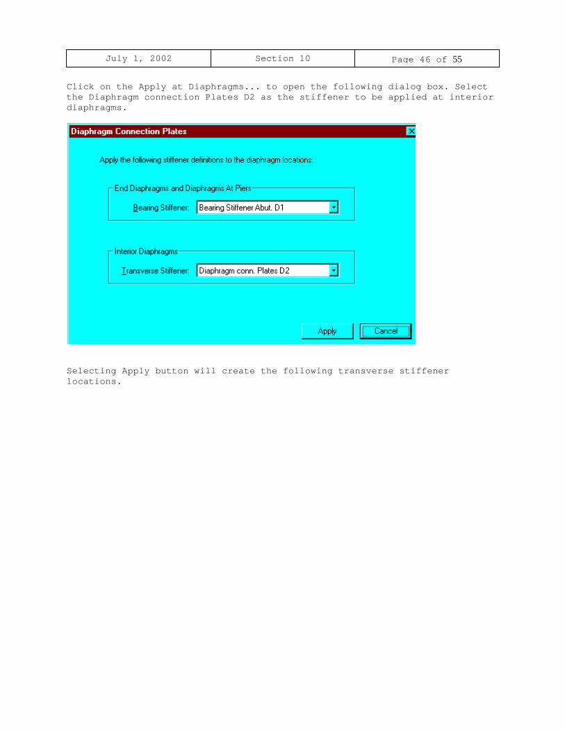
Click on the Apply at Diaphragms... to open the following dialog box. Selectthe Diaphragm connection Plates D2 as the stiffener to be applied at interiordiaphragms.
Selecting Apply button will create the following transverse stiffenerlocations.
July 1, 2002 Section 10 Page 47 of 55
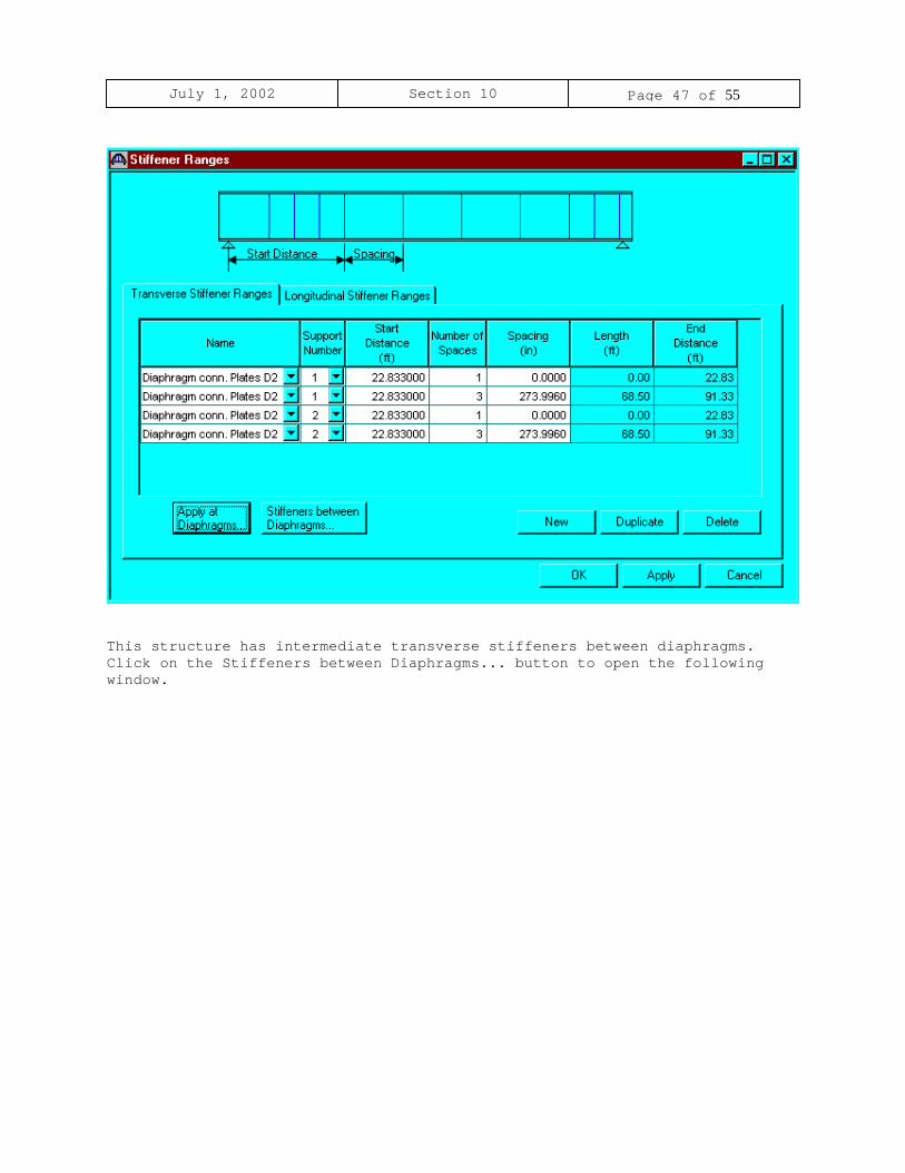
This structure has intermediate transverse stiffeners between diaphragms.Click on the Stiffeners between Diaphragms... button to open the followingwindow.

July 1, 2002 Section 10 Page 48 of 55
Enter the appropriate stiffener data i.e., the number of equal spaces betweendiaphragms and the stiffener definition.
Click the Apply button.
July 1, 2002 Section 10 Page 49 of 55
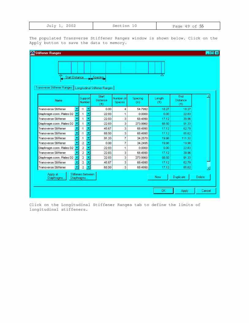
The populated Transverse Stiffener Ranges window is shown below. Click on theApply button to save the data to memory.
Click on the Longitudinal Stiffener Ranges tab to define the limits oflongitudinal stiffeners.

July 1, 2002 Section 10 Page 50 of 55
Enter the appropriate stiffener data and click the Apply button to save thedata to memory and close the window.
July 1, 2002 Section 10 Page 51 of 55
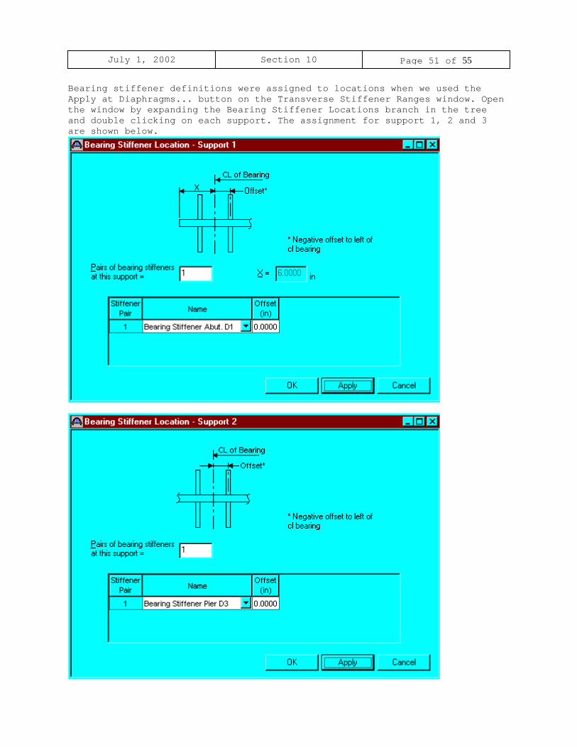
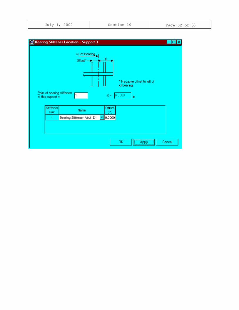
Bearing stiffener definitions were assigned to locations when we used theApply at Diaphragms... button on the Transverse Stiffener Ranges window. Openthe window by expanding the Bearing Stiffener Locations branch in the treeand double clicking on each support. The assignment for support 1, 2 and 3are shown below.
July 1, 2002 Section 10 Page 52 of 55

July 1, 2002 Section 10 Page 53 of 55
Select Plate Girder (E)(C) in the Bridge Workspace tree; open the schematic
for the girder profile by selecting the View Schematic toolbar button orthe Bridge/Schematic from the menu.

July 1, 2002 Section 10 Page 54 of 55
The results of the control LFD rating analysis are as follows:

July 1, 2002 Section 10 Page 55 of 55