color ea kit320f-8 - mouser electronics · color ea kit320f-8 general the ea kit320f graphics kit...
TRANSCRIPT
ZEPPELINSTRASSE 19 · D- 82205 GILCHINGPHONE +49-8105-778090 · FAX +49-8105-778099 · http://www.lcd-module.de
COLOR EA KIT320F-810.2010
FEATURES* 5.7" COLOR LCD GRAPHIC DISPLAY WITH MANY GRAPHICS FUNCTIONS AND FONTS* 320x240 PIXEL, 16 COLOURS WITH CFL BACKLIGHT* FONT ZOOM OF approx. 2mm UP TO approx. 80mm, FONT ROTATION, 90° STEP* SUPPLY VOLTAGE +5V±2%@320mA OR +9..35V OPTIONALLY* RS-232 OR RS-422 WITH BAUD RATE 1,200~115,200 BD* POSITIONING ACCURATE TO THE PIXEL WITH ALL FUNCTIONS* STRAIGHT LINE, POINT, AREA, AND/OR/EXOR, BAR GRAPH...* CLIPBOARD FUNCTIONS, PULL-DOWN MENUS* STORE UP TO 256 BITMAPS* UP TO 1380 MACROS PROGRAMMABLE (512 kB FLASH ONBOARD)* TEXT AND GRAPHIC CAN BE MIXED, FLASHING TEXT, INVERS TEXT* SWITCH BACKLIGHT BY SOFTWARE CONTROL (OFF, ON , HALF BRIGHTESS)* ANALOGUE TOUCH PANEL: CAN BE SET INDIVIDUALLY (e.g. 10x8 FIELDS)* DEFINE KEYS AND SWITCHES* OPERATE MENU AND BARGRAPH ADJUSTMENT BY THE USE OF TOUCH PANEL* 8 DIGITAL INPUT AND 8 OUTPUT LINES* 2 ANALOGUE INPUT 0..200mV WITH SCALING FUNCTION* CONNECTOR FOR ALPHANUMERIC DISPLAY WITH HD44780
ORDER INFORMATIONCONTROL UNIT COLOR 5.7", TOUCH PANEL, 320x240 DOTS, RS-232 EA KIT320F-8LWTPSAME BUT WITHOUT TOUCH PANEL EA KIT320F-8LW
SUPPLY VOLTAGE +9..35V= INSTEAD OF +5V= EA OPT-9/35VRS-422 INTERFACE INSTEAD OF RS-232 EA OPT-RS4224OPTO COUPLER (8xIN, 8xOUT) ON BOARD EA OPT-OPTO16ALUMINIUM BEZEL FOR MOUNTING, BLACK ANODIZED EA 0FP320F-8SWCABLE 1.5m WITH 9-PIN SUB-D (RS-232 FEMALE) EA KV24-9B
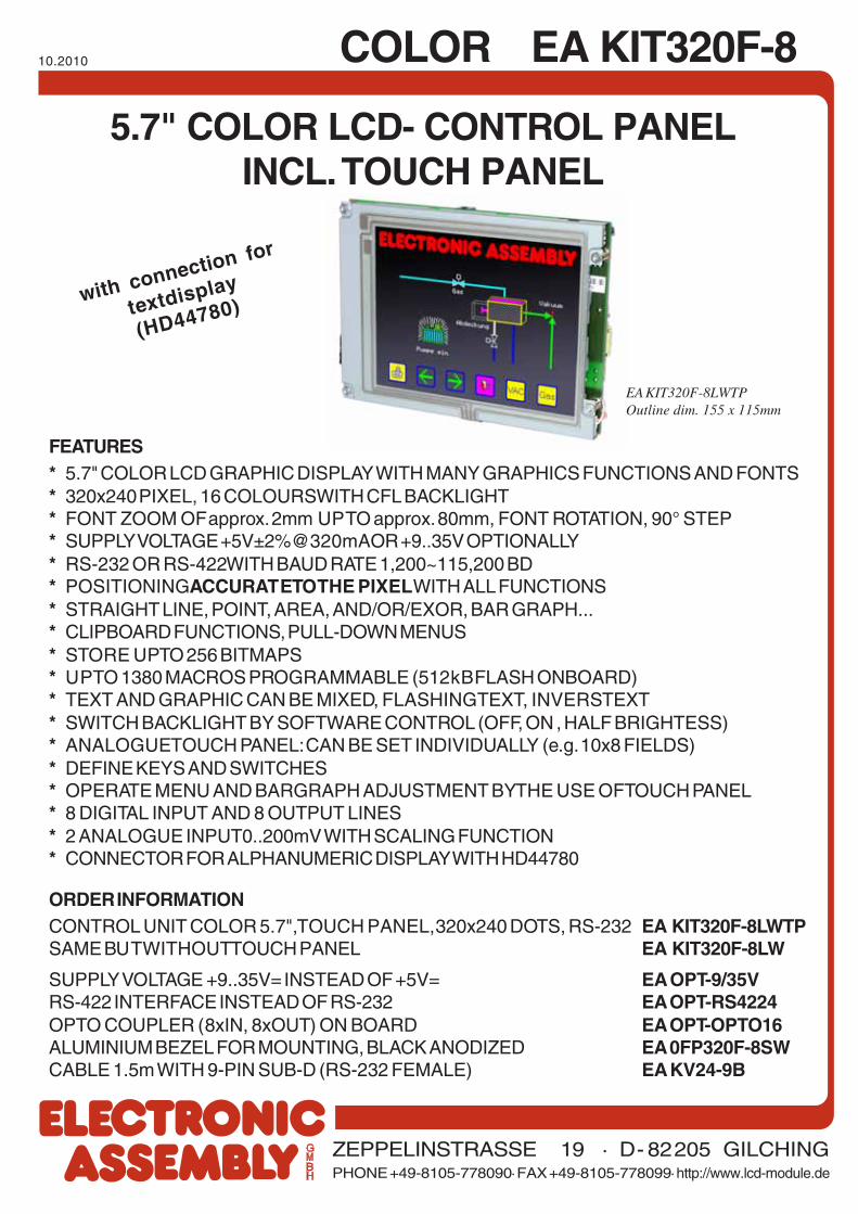
5.7" COLOR LCD- CONTROL PANELINCL. TOUCH PANEL
with connection for
textdisplay
(HD44780)
EA KIT320F-8LWTPOutline dim. 155 x 115mm
2
EA KIT320F-8 COLOR
CONTENT
GENERAL .................................................................................................................... 3
HARDWARE, CONNECTOR, PINOUT ......................................................................... 4
DIGITAL INPUT / OUTPUT, KEYBOARD INTERFACE................................................ 5~7
TOUCH PANEL .......................................................................................................... 8, 9
MACRO PROGRAMMING........................................................................................ 10, 11
CHARACTER SETS ................................................................................................. 12, 13
COLORS AND ATTRIBUTES ...................................................................................... 14
COMMAND SYNTAX, PROGRAMMING EXAMPLE .................................................... 16
COMMAND TABLES ................................................................................................ 17~22
RESPONSE OF CONTROL UNIT ............................................................................... 23
DIMENSIONS ............................................................................................................. 24
Documentation of revision
Date Type Old New Reason / Description
5.2.04 Simulator F1: help function Shift-F1: help function continous terminal functionality F1..F10
5.2.04 Data sheetPage 6: Extension for analogue inputdescription Page 22: Insert command forcalibration
6.2.04 Data sheetPage 9: Insert "Create own key form", "Usebitmap as a key", "Radio groups"
8.10.10 DisplayEA KIT320F-8CEA KIT320F-8CTP
EA KIT320F-8LWEA KIT320F-8LWTP Backlight changed from CFL into LED type
3
COLOR EA KIT320F-8GENERALThe EA KIT320F graphics kit is a fully assembled control and operating unit with a variety of integratedfunctions. The display has very compact dimensions and offers excellent super-twist contrast, whichmeans the unit can be put into operation immediately. It is controlled via the standard RS-232 orRS-422 interface. In addition to complete graphics routines for display output, the graphics kit alsocontains a wide variety of fonts. Graphics command similar to those used in high-level programminglanguages are used for programming. There is thus no longer any need for the time-consumingprogramming of character sets and graphics routines. The ease of use offered by macros and inputvia touch panel make it a real power display.
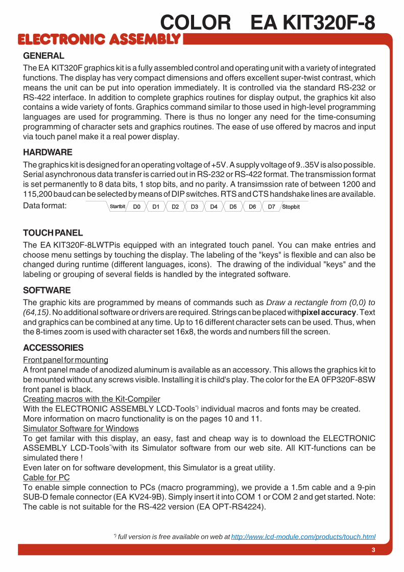
HARDWAREThe graphics kit is designed for an operating voltage of +5V. A supply voltage of 9..35V is also possible.Serial asynchronous data transfer is carried out in RS-232 or RS-422 format. The transmission formatis set permanently to 8 data bits, 1 stop bits, and no parity. A transimssion rate of between 1200 and115,200 baud can be selected by means of DIP switches. RTS and CTS handshake lines are available.Data format:
TOUCH PANELThe EA KIT320F-8LWTPis equipped with an integrated touch panel. You can make entries andchoose menu settings by touching the display. The labeling of the "keys" is flexible and can also bechanged during runtime (different languages, icons). The drawing of the individual "keys" and thelabeling or grouping of several fields is handled by the integrated software.
SOFTWAREThe graphic kits are programmed by means of commands such as Draw a rectangle from (0,0) to(64,15). No additional software or drivers are required. Strings can be placed with pixel accuracy. Textand graphics can be combined at any time. Up to 16 different character sets can be used. Thus, whenthe 8-times zoom is used with character set 16x8, the words and numbers fill the screen.
ACCESSORIESFront panel for mountingA front panel made of anodized aluminum is available as an accessory. This allows the graphics kit tobe mounted without any screws visible. Installing it is child's play. The color for the EA 0FP320F-8SWfront panel is black.Creating macros with the Kit-CompilerWith the ELECTRONIC ASSEMBLY LCD-Tools*) individual macros and fonts may be created.More information on macro functionality is on the pages 10 and 11.Simulator Software for WindowsTo get familar with this display, an easy, fast and cheap way is to download the ELECTRONICASSEMBLY LCD-Tools*)with its Simulator software from our web site. All KIT-functions can besimulated there !Even later on for software development, this Simulator is a great utility.Cable for PCTo enable simple connection to PCs (macro programming), we provide a 1.5m cable and a 9-pinSUB-D female connector (EA KV24-9B). Simply insert it into COM 1 or COM 2 and get started. Note:The cable is not suitable for the RS-422 version (EA OPT-RS4224).
*) full version is free available on web at http://www.lcd-module.com/products/touch.html

4
EA KIT320F-8 COLOR
RS-232/RS-422 CONNECTIONThe graphics kit is shipped with an RS-232 interface as standard. The pin assignment of the plug
connector (J3) is as shown in the table on the left. The J3 has a 2.54mmgrid. If the graphics kit is ordered togetherwith the EA OPT-RS4224 optionalcomponent, RS-422 drivers are fitted. Inthis case, the pin assignment is as shown inthe table on the right.The same serial data with 5V levels and TTLlogic is available at the J5 eyelet strip. Theselevels are suitable for direct connection to aµC. However, if these signals are used, 4
solder liks TXD, RXD, RTS, CTS
had to be cut before !
BAUD RATESThe baud rate can be set by means of the 3 DIP switches on the left. 9,600 baudis set at the factory (DIP 3 ON). Please note that the internal data buffer only holds128 bytes. It is therefore imperative that the RTS handshake line be queried (a levelof +10V means data can be accepted; a level of -10V means the display is busy).The data format is fixed at 8 data bits, 1 stop bit and no parity.
SUPPLY VOLTAGE / EA OPT-9/35VIn the standard model, the supply voltageof +5V is fed in via screw-type terminal J1. Inthe case of the version for 9..35V (EA OPT-9/35V), the power is supplied via J2.Important: It is imperative that the polarity iscorrect. Polarity reversal, even for a veryshort time, can cause the immediatedestruction of the entire display.
RS-422 J3 connectionPin Symbol Function1 VDD + 5V supply2 Data In- Receive data3 Data In+ Receive data4 Data Out- Transmit data5 Data Out+ Transmit data6 HS In- Handshake7 HS In+ Handshake8 HS Out- Handshake9 HS Out+ Handshake10 GND 0V ground
RS-232 J3 connectionPin Symb In/Out Function1 VDD - + 5V supply2 DCD - Strap to DTR3 DSR - Strap to DTR4 TxD Out Transmit data5 CTS In Clear to send6 RxD In Receive data7 RTS Out Request to send8 DTR - See pin 2, pin 39 - - NC10 GND - 0V ground
J5 add-onPin Symbol In/Out Function1 VU - 9..35V supply2 VDD - + 5V supply3 GND - 0V, ground4 TxD5 Out Transmit data5 RxD In Receive data6 RTS Out Request to send7 CTS In Clear to send8 RESET In H: reset9 SCL Out I2C bus, clock10 SDA In/Out I2C bus, data
On
+
++
-
--
J1+5V
AIN 1
AIN 2
RLED Kontr. Dotmatrix
J7
Kontrast
119
20
J3RS-232RS-422
115
16 2J5
110
11
92
20
J120
(nur EA OPT-RS4224)
TXD
LötbrückenRXD
RTS CTS
+-
J2+9..35V
(nur EA OPT-9/35V)
8x Eingang(nur EA OPT-OPTO16)
8x Ausgang(nur EA OPT-OPTO16)
View from rear side
Baud ratesDIP switches Data format
8,N,11 2 3ON ON ON
1200
ON ON2400
OFFON ON
4800OFF
ON9600OFF OFF
ON ON19200OFF
ON38400
OFF OFFON
57600OFF OFF
115200OFF OFF OFF

5
COLOR EA KIT320F-8DIGITAL INPUT AN OUTPUTAll control units EA KIT320F-8 are featured with 8digital input and 8 digital output lines (5V CMOS level,grounded).8 outputsEach line can be controlled individually using the"ESC Y W" command. A maximum current of 6mA canbe switched per line. This give the opportunity to drive alow power LED in direct way. To source higher currentplease use an external transistor (see applicationbelow).8 EingängeThe inputs can also be queried and evaluated directly via the serial interface("ESC Y R"). In addition to that every port change may start an individual port -or bit- macro. Each of these port macros can change the contents of the screenor switch an output, thus enabling a wide range of control functions. Command"ESC Y A 0" disables automatic port query.Port Macro: when the 8 lines are combined, up to 256 port macros can thus beaddressed.Bit Macro: watching a single line. Bit Macro 1..8 will be started when one of thelines 1..8 changes to high (rising edge). Bit Macro 9..16 will be started when oneof these lines is gong to low (falling edge).If both macros (Port and Bit macro) are defined, every change will start Bit Macrofirst and then Port Makro. If there's no macro defined, port status wil be sent viaRS232/RS422.To create the port macros you need a PC and the EA DISK320F floppy disk.Note: The logic circuitry is designed for slow operations; in other words, morethan 3 changes per second cannot be easily executed. Open input are highbecause of internal100 kOhm pull-up.
INPUT AND OUTPUT VIA OPTOCOUPLER (EA OPT-OPTO16)Digital input and output are optionally featured withoptocoupler (EA OPT-OPTO16). All the 8 inputsand 8 outputs are isolated from the rest of theelectronic components as well as each other. Theconnection is made via 16 different screw-typeterminals.All input lines can be connected with 5..35Vdirectly. Level above 4V are H-level, a voltagebelow 2V stay for L-level. Voltage between 2V and4V are undefined.The collector and emitter of a transistor is brought out at the screw-type terminals as the output. Eachoutput can switch a maximum of 10mA.Note: The negative pole of each screw-type terminal can be interconnected by closing the solder strapsLBI1..8 and LBO1..8. These solder straps can also be connected to system ground GND (solder 0Ωstrap RGND).Note: The optocouplers invert the input logic (all inputs open: port macro 255). It is advisable here (inthe power-on macro, for example) to use the "ESC Y I 1" command to evaluate the inputs inversely (allinputs open: port macro 0).
Input and output J120Pi Symbol Function Pi Symbol Function1 VDD +5V supply 2 GND 0V, Ground
3 OUT1 / MO8 Port output 1Matrix output 8 4 IN1 / MI8 Port input 1
Matrix input 8
5 OUT2 / MO7 Port output 2Matrix output 7 6 IN2 / MI7 Port input 2
Matrix input 7
7 OUT3 / MO6 Port output 3Matrix output 6
8 IN3 / MI6 Port input 3Matrix input 6
9 OUT4 / MO5 Port output 4Matrix output 5 10 IN4 / MI5 Port input 4
Matrix input 5
11 OUT5 / MO4 Port output 5Matrix output 4 12 IN5 / MI4 Port input 5
Matrix input 4
13 OUT6 / MO3 Port output 6Matrix output 3 14 IN6 / MI3 Port input 6
Matrix input 3
15 OUT7 / MO2 Port output 7Matrix output 2 16 IN7 / MI2 Port input 7
Matrix input 2
17 OUT8 / MO1 Port output 8Matrix output 1
18 IN8 / MI1 Port input 8Matrix input 1
19 GND 0V, Ground 20 VDD +5V supply

6
EA KIT320F-8 COLOR
INTERFACE FOR TEXT DISPLAY WITH HD44780Eyelet J7 is a interface for an external alphanumeric LCD withHD44780 controller onboard. All popular sizes from 1x8 up to 4x20(2x40) characters are supported. Software with terminal functions viacommand 'ESC T xx' is already built-in. By command 'ESC L xx' low levelprogramming for controller HD44780 is possible. Potentiometer forcontrast adjustment is built-in, too. Customer is able to add a seriesresistor RLED for LED backlight on-board.
HD44780 LCD-interface J6 + J7Pin Symbol Level Function1 VSS L Power supply, Ground2 VDD H Power supply +5V3 VEE - Contrast voltage 0V~5V4 RS H / L Register Select5 R/W H / L H: Read / L: Write6 E H Enable7 D0 H / L Data line 0 (LSB)8 D1 H / L Data line 19 D2 H / L Data line 2
10 D3 H / L Data line 311 D4 H / L Data line 412 D5 H / L Data line 513 D6 H / L Data line 614 D7 H / L Data line 715 A - Anode for LED (RLED)16 K L Cathode f. LED (=VSS)
ANALOGUE INPUT AIN1AUND AIN2 PAGE 20
For analogue measurement 2 inputs with a range of 0..+250mV are available. Each input is grounded(GND) and DC impedance is 10kΩ. Please make shure that only positive voltages will be supplyedthere. Internal resolution is 10 Bit, equal to a 3-digit DVM modul. Linearity (after adjustment) is around0.5%.AdjustmentAnalogue inputs are not calibrated when shipped out. A procedure for adjustment may be like that:1.) Put a well known voltage within a range of 150-250mV to analogu input (example: 200mV, AIN1)2.) Run command for calibration (see page 20). Example: "ESC V @ 1 200.0 NUL".This command may be put into a Touch-macro, too, which will be started touching the display.MeasurementEach input query can be done via RS-232 (RS-422) or directly shown on display (as digits or bargraphin various colors and sizes).Best way for direct visualisation are Process-macros or one of Analogue-macros (e.g. starting at everyvoltage change, or above/below a limit).Both input lines are scaleable from 0 to ±9999.9. Scaling will be done via definition at 2 votages(value1 > string1, value2 > string2).
Divider 1:100 for voltage 0..25V
++
--
AIN1
12V
AIN2
EA KIT320F-8CTP
GND
GND
10k
10k
+1 MOhm
Application example
++
--
AIN1
AIN2
EA KIT320F-8CTP
GND
GND
10k
10k
+
-
4..20mA
10 Ohm
7
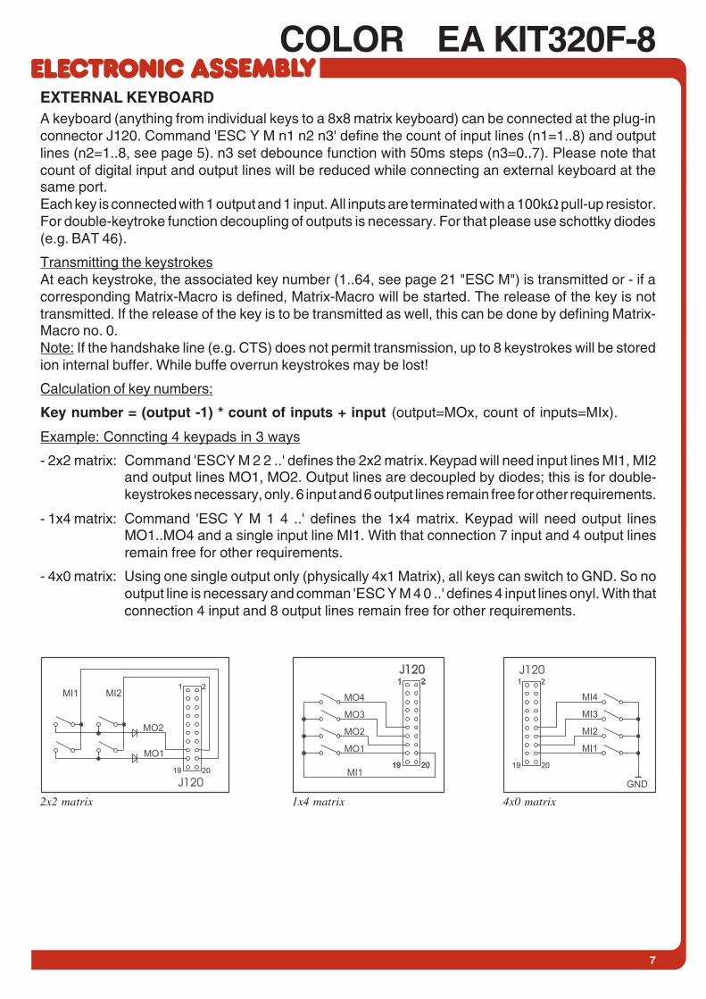
COLOR EA KIT320F-8EXTERNAL KEYBOARDA keyboard (anything from individual keys to a 8x8 matrix keyboard) can be connected at the plug-inconnector J120. Command 'ESC Y M n1 n2 n3' define the count of input lines (n1=1..8) and outputlines (n2=1..8, see page 5). n3 set debounce function with 50ms steps (n3=0..7). Please note thatcount of digital input and output lines will be reduced while connecting an external keyboard at thesame port.Each key is connected with 1 output and 1 input. All inputs are terminated with a 100kΩ pull-up resistor.For double-keytroke function decoupling of outputs is necessary. For that please use schottky diodes(e.g. BAT 46).
Transmitting the keystrokesAt each keystroke, the associated key number (1..64, see page 21 "ESC M") is transmitted or - if acorresponding Matrix-Macro is defined, Matrix-Macro will be started. The release of the key is nottransmitted. If the release of the key is to be transmitted as well, this can be done by defining Matrix-Macro no. 0.Note: If the handshake line (e.g. CTS) does not permit transmission, up to 8 keystrokes will be storedion internal buffer. While buffe overrun keystrokes may be lost!
Calculation of key numbers:
Key number = (output -1) * count of inputs + input (output=MOx, count of inputs=MIx).
Example: Conncting 4 keypads in 3 ways
- 2x2 matrix: Command 'ESC Y M 2 2 ..' defines the 2x2 matrix. Keypad will need input lines MI1, MI2and output lines MO1, MO2. Output lines are decoupled by diodes; this is for double-keystrokes necessary, only. 6 input and 6 output lines remain free for other requirements.
- 1x4 matrix: Command 'ESC Y M 1 4 ..' defines the 1x4 matrix. Keypad will need output linesMO1..MO4 and a single input line MI1. With that connection 7 input and 4 output linesremain free for other requirements.
- 4x0 matrix: Using one single output only (physically 4x1 Matrix), all keys can switch to GND. So nooutput line is necessary and comman 'ESC Y M 4 0 ..' defines 4 input lines onyl. With thatconnection 4 input and 8 output lines remain free for other requirements.
GND
MI4
MI3
MI2
MI1
1 2
19 20
J120
4x0 matrix1x4 matrix
MO1
MI1
MO2
MI21 2
19 20
J120
2x2 matrix

8
EA KIT320F-8 COLORTOUCH PANEL (EA KIT320F-8LWTP ONLY)
Version EA KIT320F-8CTP comes with an integrated touch panel,analogue resistive type. Up to 80 touch areas can be defined (summaryof all keys, switch, menue, bargraph-input). This control unit supports allof them with many comfortable commands (see page 18). When thetouch keys are touched, they can be automatically inverted and a tonecan sound, indicating they have been touched. At the same time, thedefined return code of the key is transmitted via the serial interface, oran internal touch macro with the number of the return code is started. Pre-definition of a keypad when using
commands 'ESC AC' or 'ESC AG'
TOUCH PANEL ADJUSTMENTTouch panel is ready to use and well adjusted when module will be shipped out. Because of agingand attrition a re-adjustment may be necessary.Adjustment procedure:1. While switching on display, touch the display surface and keep it touched until display shows the
question "touch adjustment ?" (or transmit 'ESC @' command).2. Within 1 second touch again the display surface for min. 1 second.3. Follow instructions for adjustment (touch 2 points topleft and bottomright ).
FRAMES AND KEY STYLESBoth commands draw box frame and draw touch defines key style.You can choose one fo 20 internal defines frame types; furthermoresome personal styles can be defined via compiler k320comp.exe(see DOKU.DOC on floppy disk EA DISK320F: Compiler code"BORDER")All of them can be used in various sizes via coordinates. Each frameis split into 4 segments: the edges (not for type 1-5), outer frame,inner frame and filling.Each segment will get an individual colour and attribute. This willgive the user the opportunity, when touching a field, the individualpart of the key will be inverted only.
9
COLOR EA KIT320F-8
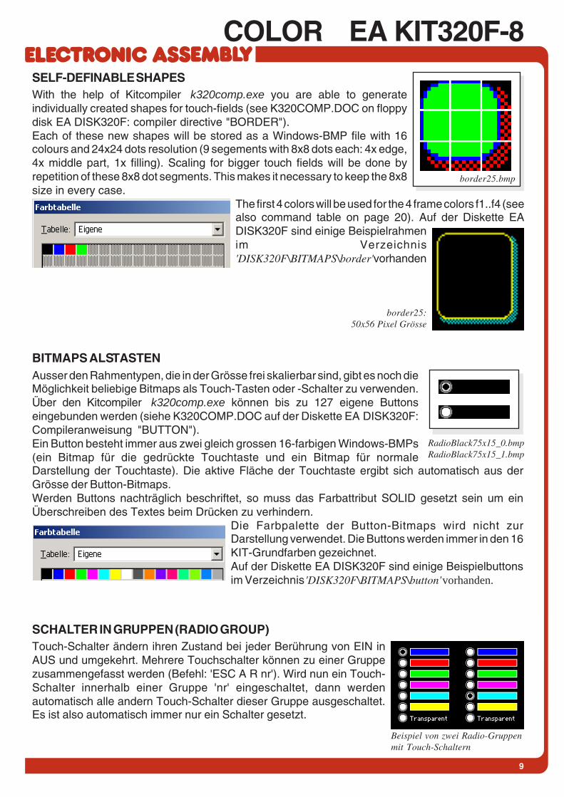
BITMAPS ALS TASTENAusser den Rahmentypen, die in der Grösse frei skalierbar sind, gibt es noch dieMöglichkeit beliebige Bitmaps als Touch-Tasten oder -Schalter zu verwenden.Über den Kitcompiler k320comp.exe können bis zu 127 eigene Buttonseingebunden werden (siehe K320COMP.DOC auf der Diskette EA DISK320F:Compileranweisung "BUTTON").Ein Button besteht immer aus zwei gleich grossen 16-farbigen Windows-BMPs(ein Bitmap für die gedrückte Touchtaste und ein Bitmap für normaleDarstellung der Touchtaste). Die aktive Fläche der Touchtaste ergibt sich automatisch aus derGrösse der Button-Bitmaps.Werden Buttons nachträglich beschriftet, so muss das Farbattribut SOLID gesetzt sein um einÜberschreiben des Textes beim Drücken zu verhindern.
Die Farbpalette der Button-Bitmaps wird nicht zurDarstellung verwendet. Die Buttons werden immer in den 16KIT-Grundfarben gezeichnet.Auf der Diskette EA DISK320F sind einige Beispielbuttonsim Verzeichnis 'DISK320F\BITMAPS\button' vorhanden.
SCHALTER IN GRUPPEN (RADIO GROUP)Touch-Schalter ändern ihren Zustand bei jeder Berührung von EIN inAUS und umgekehrt. Mehrere Touchschalter können zu einer Gruppezusammengefasst werden (Befehl: 'ESC A R nr'). Wird nun ein Touch-Schalter innerhalb einer Gruppe 'nr' eingeschaltet, dann werdenautomatisch alle andern Touch-Schalter dieser Gruppe ausgeschaltet.Es ist also automatisch immer nur ein Schalter gesetzt.
SELF-DEFINABLE SHAPESWith the help of Kitcompiler k320comp.exe you are able to generateindividually created shapes for touch-fields (see K320COMP.DOC on floppydisk EA DISK320F: compiler directive "BORDER").Each of these new shapes will be stored as a Windows-BMP file with 16colours and 24x24 dots resolution (9 segements with 8x8 dots each: 4x edge,4x middle part, 1x filling). Scaling for bigger touch fields will be done byrepetition of these 8x8 dot segments. This makes it necessary to keep the 8x8size in every case.
The first 4 colors will be used for the 4 frame colors f1..f4 (seealso command table on page 20). Auf der Diskette EADISK320F sind einige Beispielrahmenim Verzeichnis'DISK320F\BITMAPS\border' vorhanden
border25:50x56 Pixel Grösse
Beispiel von zwei Radio-Gruppenmit Touch-Schaltern
RadioBlack75x15_0.bmpRadioBlack75x15_1.bmp
border25.bmp

10
EA KIT320F-8 COLORMACRO PROGRAMMINGSingle or multiple command sequences can be grouped together in macros and stored in the Data-FLASH. You can then start them by using the Run macro commands. There are several different typesof macros:Normal Macros (0..255)These are started by means of a command via the serial interface (ESC MN xx) or from another macro.A series of macros occurring one after the other can be called cyclically (movie, hourglass, multi-pagehelp text). This kind of automatic macro will run until data from RS-232/422 will be received or untilanother macro will be started (Touch- Port- or matrix-Macro)Touch Macros (1..255)These are started when you touch a touch field (in versions with a touch panel - TP) or command 'ESCMT xx' will be received. Touch macro no. 0 is different: It is started when you release a key.Menu Macros (1..255)will start after a choice in menu entry or by command 'ESC MM xx'.Bit Macros (1..8) and (9..16)will start voltage at a single line IN 1..8 (bitweise) will change or by command 'ESC MB xx'. Bit- Macro1..8 are good for rising edge and Bit Macro 9..16 are good for falling edge at input 1..8.Port macros (0..255)These are started when voltage (binary) is applied to IN 1..8 or by command 'ESC MP xx'.Matrix Macros (0..64)Matrix Macro 1..64: start when keypressed or by command 'ESC MX xx'.Matrix Macro 0: start after release of key or by command.For more details please refer to page 7.Analogue Macros (0..19)will start whenever voltage chages or limit exceeds or bycommand 'ESC MV xx'. See table at the right:Process Macros (0..255)automatic start at fixed periode (0.1s up to 25s) or by command'ESC MC xx'. Up to 16 individual process may be defined bycommand 'ESC MD ..'. These Process Makro will never bestopped by other commands or activities.Power-on MacroNormal macro no. 0 is different: It is executed automatically afterpower-on. It allows you to switch off the cursor and define anopening screen, for example.Reset MacroStart after external reset or power supply break-down beow 4.7V (VDD-VSS).Watchdog MacroStart after system error.
Note: Doing with Power-On-, Reset- or Watchdog Macro an endless loop, display can no longer bereached. In that case: set DIP switch no. 5 to ON position, power-off, power-on, and then DIP 5 backto OFF. All Macros are need to be downloaded again.
Analogue MacroMacro No.
Macro starts atAIN1 AIN2
0 10 every change of input voltage1 11 falling input voltage2 12 rising input voltage3 13 below lower limit4 14 above lower limit5 15 below upper limit6 16 above upper limit7 17 outside of both limits8 18 inside of both limits9 19 lower than other channel

11
COLOR EA KIT320F-8CREATING INDIVIDUAL MACROS AND IMAGES- ELECTRONIC ASSEMBLY LCD-Tools*), which contains a kit editor, kit compiler and examples and
fonts (for Windows PCs)- A PC with a serial COM interfaceTo define a sequence of commands as a macro, all the commands are written to a file on the PC (e.g.DEMO.KMC). You specify which character sets are to be integrated and which command sequencesare to be in which macros.If the macros are defined using the kit editor, you start the eDIP320 compiler using F5. This createsa file called DEMO.DF. If the display is connected to the PC, this file is automatically downloaded inthe display’s data flash memory.You will find a detailed description of the programming of the macros together with examples in theELECTRONIC ASSEMBLY LCD-Tools*) help system.
WRITE PROTECTION FOR PROGRAMMED MACROSYou can use DIP switch # 6 and set to OFF position to prevent the programmed macros, images andfonts from being inadvertently overwritten. Re-programming the FLASH memory need to have the DIPswitch #6 at ON.
STORING 256 IMAGES IN THE ON-BOARD FLASH PROMTo reduce the transmission times of the serial interface or to save storage space in the processorsystem, up to 256 images can be stored in internal FLASH PROM. They can be called using the "ESCU I" command via the serial interface or from within any macro. All the images can be used in theWindows .BMP format (monochrome or 16 colors). They can be created and edit using widely availablesoftware such as Windows Paint or Photoshop.
*) full version is free available on web at http://www.lcd-module.com/products/touch.html
12
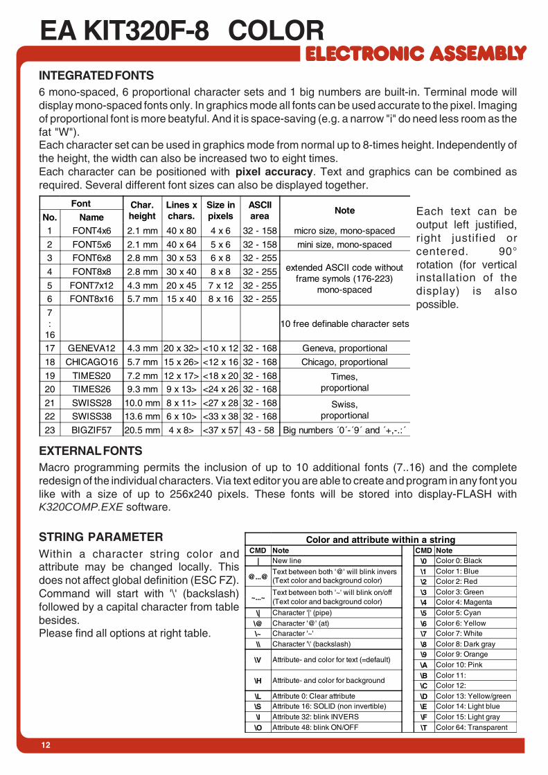
EA KIT320F-8 COLORINTEGRATED FONTS6 mono-spaced, 6 proportional character sets and 1 big numbers are built-in. Terminal mode willdisplay mono-spaced fonts only. In graphics mode all fonts can be used accurate to the pixel. Imagingof proportional font is more beatyful. And it is space-saving (e.g. a narrow "i" do need less room as thefat "W").Each character set can be used in graphics mode from normal up to 8-times height. Independently ofthe height, the width can also be increased two to eight times.Each character can be positioned with pixel accuracy. Text and graphics can be combined asrequired. Several different font sizes can also be displayed together.
Each text can beoutput left justified,right justified orcentered. 90°rotation (for verticalinstallation of thedisplay) is alsopossible.
Font Char.height
Lines xchars.
Size inpixels
ASCIIarea
NoteNo. Name1 FONT4x6 2.1 mm 40 x 80 4 x 6 32 - 158 micro size, mono-spaced
2 FONT5x6 2.1 mm 40 x 64 5 x 6 32 - 158 mini size, mono-spaced
3 FONT6x8 2.8 mm 30 x 53 6 x 8 32 - 255extended ASCII code without
frame symols (176-223)mono-spaced
4 FONT8x8 2.8 mm 30 x 40 8 x 8 32 - 255
5 FONT7x12 4.3 mm 20 x 45 7 x 12 32 - 255
6 FONT8x16 5.7 mm 15 x 40 8 x 16 32 - 255
7:
1610 free definable character sets
17 GENEVA12 4.3 mm 20 x 32> <10 x 12 32 - 168 Geneva, proportional
18 CHICAGO16 5.7 mm 15 x 26> <12 x 16 32 - 168 Chicago, proportional
19 TIMES20 7.2 mm 12 x 17> <18 x 20 32 - 168 Times,proportional20 TIMES26 9.3 mm 9 x 13> <24 x 26 32 - 168
21 SWISS28 10.0 mm 8 x 11> <27 x 28 32 - 168 Swiss,proportional22 SWISS38 13.6 mm 6 x 10> <33 x 38 32 - 168
23 BIGZIF57 20.5 mm 4 x 8> <37 x 57 43 - 58 Big numbers ´0´-´9´ and ´+,-.:´
EXTERNAL FONTSMacro programming permits the inclusion of up to 10 additional fonts (7..16) and the completeredesign of the individual characters. Via text editor you are able to create and program in any font youlike with a size of up to 256x240 pixels. These fonts will be stored into display-FLASH withK320COMP.EXE software.
Color and attribute within a stringCMD Note CMD Note
| New line \0 Color 0: Black
@...@Text between both '@' will blink invers(Text color and background color)
\1 Color 1: Blue\2 Color 2: Red
~...~Text between both '~' will blink on/off(Text color and background color)
\3 Color 3: Green\4 Color 4: Magenta
\| Character '|' (pipe) \5 Color 5: Cyan
\@ Character '@' (at) \6 Color 6: Yellow\~ Character '~' \7 Color 7: White
\\ Character '\' (backslash) \8 Color 8: Dark gray
\V Attribute- and color for text (=default)\9 Color 9: Orange
\A Color 10: Pink
\H Attribute- and color for background\B Color 11:\C Color 12:
\L Attribute 0: Clear attribute \D Color 13: Yellow/green\S Attribute 16: SOLID (non invertible) \E Color 14: Light blue
\I Attribute 32: blink INVERS \F Color 15: Light gray
\O Attribute 48: blink ON/OFF \T Color 64: Transparent
STRING PARAMETERWithin a character string color andattribute may be changed locally. Thisdoes not affect global definition (ESC FZ).Command will start with '\' (backslash)followed by a capital character from tablebesides.Please find all options at right table.
13
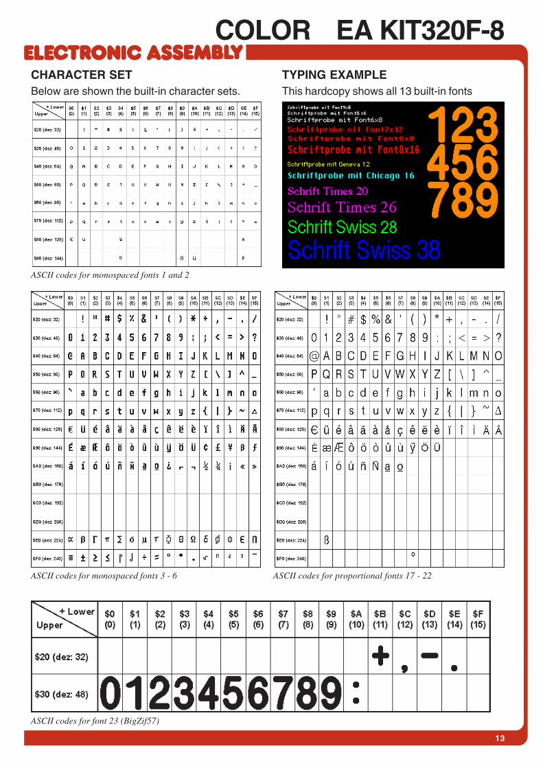
COLOR EA KIT320F-8TYPING EXAMPLEThis hardcopy shows all 13 built-in fonts
ASCII codes for monospaced fonts 3 - 6 ASCII codes for proportional fonts 17 - 22
ASCII codes for font 23 (BigZif57)
ASCII codes for monospaced fonts 1 and 2
CHARACTER SETBelow are shown the built-in character sets.
14
EA KIT320F-8 COLOR
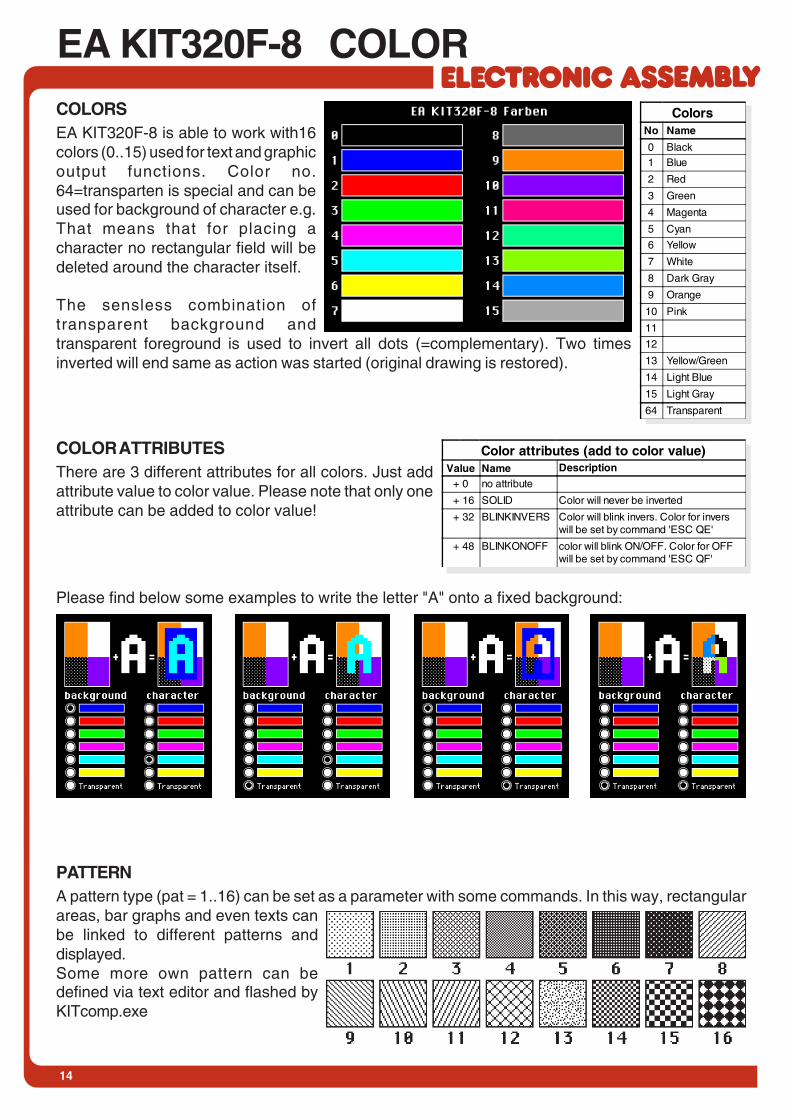
PATTERNA pattern type (pat = 1..16) can be set as a parameter with some commands. In this way, rectangularareas, bar graphs and even texts canbe linked to different patterns anddisplayed.Some more own pattern can bedefined via text editor and flashed byKITcomp.exe
COLORSEA KIT320F-8 is able to work with16colors (0..15) used for text and graphicoutput functions. Color no.64=transparten is special and can beused for background of character e.g.That means that for placing acharacter no rectangular field will bedeleted around the character itself.
The sensless combination oftransparent background andtransparent foreground is used to invert all dots (=complementary). Two timesinverted will end same as action was started (original drawing is restored).
COLOR ATTRIBUTESThere are 3 different attributes for all colors. Just addattribute value to color value. Please note that only oneattribute can be added to color value!
Please find below some examples to write the letter "A" onto a fixed background:
Color attributes (add to color value)Value Name Description
+ 0 no attribute
+ 16 SOLID Color will never be inverted
+ 32 BLINKINVERS Color will blink invers. Color for inverswill be set by command 'ESC QE'
+ 48 BLINKONOFF color will blink ON/OFF. Color for OFFwill be set by command 'ESC QF'
ColorsNo Name
0 Black1 Blue
2 Red
3 Green
4 Magenta
5 Cyan
6 Yellow
7 White
8 Dark Gray
9 Orange
10 Pink
11
12
13 Yellow/Green
14 Light Blue
15 Light Gray
64 Transparent

15
COLOR EA KIT320F-8
THIS PAGE IS INTENTIONALLY LEFT BLANK
16
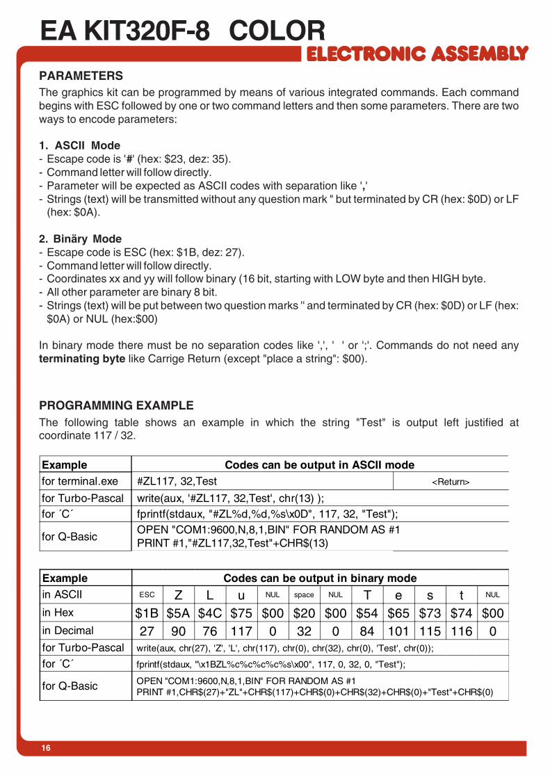
EA KIT320F-8 COLORPARAMETERSThe graphics kit can be programmed by means of various integrated commands. Each commandbegins with ESC followed by one or two command letters and then some parameters. There are twoways to encode parameters:
1. ASCII Mode- Escape code is '#' (hex: $23, dez: 35).- Command letter will follow directly.- Parameter will be expected as ASCII codes with separation like ','- Strings (text) will be transmitted without any question mark " but terminated by CR (hex: $0D) or LF
(hex: $0A).
2. Binäry Mode- Escape code is ESC (hex: $1B, dez: 27).- Command letter will follow directly.- Coordinates xx and yy will follow binary (16 bit, starting with LOW byte and then HIGH byte.- All other parameter are binary 8 bit.- Strings (text) will be put between two question marks '' and terminated by CR (hex: $0D) or LF (hex:
$0A) or NUL (hex:$00)
In binary mode there must be no separation codes like ',', ' ' or ';'. Commands do not need anyterminating byte like Carrige Return (except "place a string": $00).
PROGRAMMING EXAMPLEThe following table shows an example in which the string "Test" is output left justified atcoordinate 117 / 32.
Example Codes can be output in ASCII modefor terminal.exe #ZL117, 32,Test <Return>
for Turbo-Pascal write(aux, '#ZL117, 32,Test', chr(13) );for ´C´ fprintf(stdaux, "#ZL%d,%d,%s\x0D", 117, 32, "Test");
for Q-Basic OPEN "COM1:9600,N,8,1,BIN" FOR RANDOM AS #1 PRINT #1,"#ZL117,32,Test"+CHR$(13)
Example Codes can be output in binary modein ASCII ESC Z L u NUL space NUL T e s t NUL
in Hex $1B $5A $4C $75 $00 $20 $00 $54 $65 $73 $74 $00in Decimal 27 90 76 117 0 32 0 84 101 115 116 0for Turbo-Pascal write(aux, chr(27), 'Z', 'L', chr(117), chr(0), chr(32), chr(0), 'Test', chr(0));
for ´C´ fprintf(stdaux, "\x1BZL%c%c%c%c%s\x00", 117, 0, 32, 0, "Test");
for Q-Basic OPEN "COM1:9600,N,8,1,BIN" FOR RANDOM AS #1 PRINT #1,CHR$(27)+"ZL"+CHR$(117)+CHR$(0)+CHR$(32)+CHR$(0)+"Test"+CHR$(0)
17
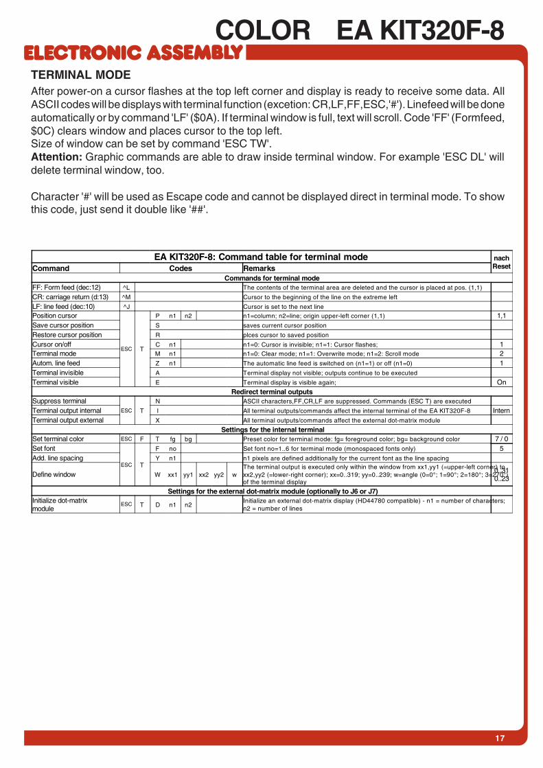
COLOR EA KIT320F-8TERMINAL MODEAfter power-on a cursor flashes at the top left corner and display is ready to receive some data. AllASCII codes will be displays with terminal function (excetion: CR,LF,FF,ESC,'#'). Linefeed will be doneautomatically or by command 'LF' ($0A). If terminal window is full, text will scroll. Code 'FF' (Formfeed,$0C) clears window and places cursor to the top left.Size of window can be set by command 'ESC TW'.Attention: Graphic commands are able to draw inside terminal window. For example 'ESC DL' willdelete terminal window, too.
Character '#' will be used as Escape code and cannot be displayed direct in terminal mode. To showthis code, just send it double like '##'.
EA KIT320F-8: Command table for terminal mode nachResetCommand Codes Remarks
Commands for terminal modeFF: Form feed (dec:12) ^L The contents of the terminal area are deleted and the cursor is placed at pos. (1,1)
CR: carriage return (d:13) ^M Cursor to the beginning of the line on the extreme left
LF: line feed (dec:10) ^J Cursor is set to the next line
Position cursor
ESC T
P n1 n2 n1=column; n2=line; origin upper-left corner (1,1) 1,1Save cursor position S saves current cursor position
Restore cursor position R plces cursor to saved position
Cursor on/off C n1 n1=0: Cursor is invisible; n1=1: Cursor flashes; 1Terminal mode M n1 n1=0: Clear mode; n1=1: Overwrite mode; n1=2: Scroll mode 2Autom. line feed Z n1 The automatic line feed is switched on (n1=1) or off (n1=0) 1Terminal invisible A Terminal display not visible; outputs continue to be executed
Terminal visible E Terminal display is visible again; OnRedirect terminal outputs
Suppress terminalESC T
N ASCII characters,FF,CR,LF are suppressed. Commands (ESC T) are executed
Terminal output internal I All terminal outputs/commands affect the internal terminal of the EA KIT320F-8 InternTerminal output external X All terminal outputs/commands affect the external dot-matrix module
Settings for the internal terminalSet terminal color ESC F T fg bg Preset color for terminal mode: fg= foreground color; bg= background color 7 / 0Set font
ESC T
F no Set font no=1..6 for terminal mode (monospaced fonts only) 5Add. line spacing Y n1 n1 pixels are defined additionally for the current font as the line spacing
Define window W xx1 yy1 xx2 yy2 wThe terminal output is executed only within the window from xx1,yy1 (=upper-left corner) toxx2,yy2 (=lower-right corner); xx=0..319; yy=0..239; w=angle (0=0°; 1=90°; 2=180°; 3=270°)of the terminal display
0..310..23
Settings for the external dot-matrix module (optionally to J6 or J7)Initialize dot-matrixmodule
ESC T D n1 n2Initialize an external dot-matrix display (HD44780 compatible) - n1 = number of characters;n2 = number of lines

18
EA KIT320F-8 COLORALL COMMANDS AT A GLANCEThe following command tables will give an overview of all built-in functions of EA KIT320F-8.After power-on or reset, some functions are set to a particular value (see last column 'After reset' intable). Please not that all the settings can be overwritten by creating a power-on macro.
EA KIT320F-8: Command table 1 AfterresetCommand Codes Remarks
Display commands (effect on the entire display)Set display color ESC F D fg bg Defines color for display and areas: fg=foreground color; bg=background color 7Delete display
ESC D
L Delete display contents (all pixels to background color)
Fill display S Fill display contents (all pixels to foreground color)
Fill display with color F co Fill complete display content with color co
Invert display I Invert display content (all colors without SOLID attribute)
Switch display off A Display contents become invisible but are retained, commands continue to be possible
Switch display on E Display contents become visible again On
Display update U n1n1=0: Display outputs are no longer visible (but continue to be executed)n1=1: Display outputs are visible immediatelyn1=2: Refresh display contents (previous outputs become visible)
1
Rechteckige Bereiche verändern / zeichnenDelete area
ESC R
L xx1 yy1 xx2 yy2 Delete an area from xx1,yy1 to xx2,yy2 (fill with background color)
Fill area S xx1 yy1 xx2 yy2 Fill an area from xx1,yy1 to xx2,yy2 (fill with foreground color)
Fill area with color F xx1 yy1 xx2 yy2 co Fill an area from xx1,yy1 to xx2,yy2 with color co
Invert area I xx1 yy1 xx2 yy2 Invert an area from xx1,yy1 to xx2,yy2 (all colors except those with SOLID attribute)
Area with fill pattern M xx1 yy1 xx2 yy2 n1 Draw an area from xx1,yy1 to xx2,yy2 with pattern n1 (uses display colors)
Set colors for box comandESC
F O fg bg fc fg=foreground color; bg=pattern and background color; fc=color for frame 7,0,7Draw box R O xx1 yy1 xx2 yy2 n1 Draw a rectangle xx1,yy1 to xx2,yy2 with fill pattern n1
Set color for frameESC
F R f1 f2 f3 f4 Frame segments: f1=edges; f2=frame outside; f3=frame inside; f4=filling 7070Draw frame box R T xx1 yy1 xx2 yy2 n1 Draw a frame box of the type n1 from xx1,yy1 to xx2,yy2
Draw straight lines and pointsSet color for lines ESC F G fg bg Colors: fg = color for line; bg = pattern background 7,64Draw rectangle
ESC G
R xx1 yy1 xx2 yy2 Draw four straight lines as a rectangle from xx1,yy1 to xx2,yy2
Draw straight line D xx1 yy1 xx2 yy2 Draw straight line from xx1,yy1 to xx2,yy2
Continue straight line W xx1 yy1 Draw a straight line from last end point to xx1, yy1 0Draw point P xx1 yy1 Set one point at coordinates xx1, yy1
Point size/line thickness Z n1 n2 n1 = X point size (1..15); n2 = Y point size (1..15); 1,1Pattern M n1 Set straight line/point pattern no. n1; 0 = do not use pattern 0
Comands for outputting strings
Set text color ESC F Z fg bg Color for string and character: fg = text color; bg = background color 7
Output string L: leftjustified, C: centered R:right justified
ESC Z
Lxx1 yy1 text
... NUL
A string (...) is output to xx1,yy1. ´NUL´ ($00), 'LF' ($0A) or 'CR' ($0D) = end of string;several lines are separated by the character '|' ($7C);;text between two '~' ($7E) characters flashes on/off;text between two '@' ($40) characters flashes inversely;
CR
Set font F n1 Set font with the number n1 (1..23) 5Font zoom factor Z n1 n2 n1 = X zoom factor (1x..8x); n2 = Y zoom factor (1x..8x) 1,1Add. line spacing Y n1 Insert n1 pixels between two lines of text as additional line spacing
Text angle W n1 Text output angle: n1=0: 0°; n1=1: 90°; n1=2: 180°; n1=3: 270°; 0Text pattern M n1 Link text with pattern no. n1; 0 = do not link text with pattern 0String for terminal ESC Z T text ... Command for outputting a string in a macro to the terminal
Bitmap image commands
Load image
ESC U
L xx1 yy1 data ... Load an image to xx1,yy1; see EA DISK320F for image structure and image data, useBMP2BH7.EXE to convert from *.BMP
Load internal image I xx1 yy1 no Load internal image with the no. (0..255) from FLASH-PROM to xx1,yy1
Send hard copy H A full image is requested in Windows BMP format. The image header is sent first viaRS232, followed by the actual image data (77878 bytes).
Commands for monochrome bitmapsSet bitmap colors ESC F U fg bg painting color for monchrome bitmaps fg = foreground color; bg = background color 7,0Image zoom factor
ESC U
Z n1 n2 n1 = X zoom factor (1x..8x); n2 = Y zoom factor (1x..8x) 1,1Image angle W n1 Output angle: n1=0: 0°; n1=1: 90°; n1=2: 180°; n1=3: 270°; 0Image pattern M n1 Link image with pattern no. n1; 0 = do not link image with pattern 0
Commands for colored bitmaps (16 colors)
Attribut for colored bitmap
ESC U
A n1 n1=0 no attribute for colored bitmaps; n1=16 bitmap is non ivertable (SOLID)n1=32 itmap is blinking On/Off; n1=48 bitmap is blinking invers 16
Set color palette P n1 n1=0: no palette will be used; colors are internal 0..15 like defined on page 133 different palettes n1=1..3 can be used for 3 bitmaps with individual palettes
1
Transparency for bitmap T n1 n1=0 show picture with all 16 colors (rectangular); n1=1 color of the first dot at top leftside will be defined as transparent (like a mask) 0
19
COLOR EA KIT320F-8
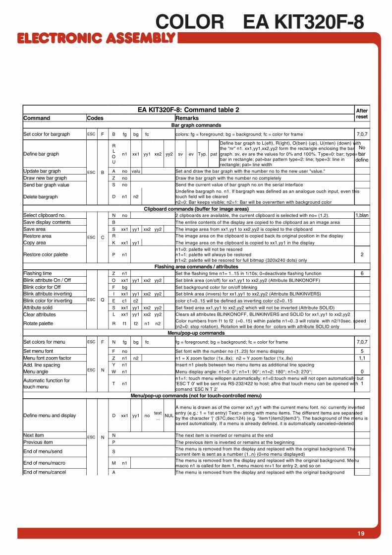
EA KIT320F-8: Command table 2 AfterresetCommand Codes Remarks
Bar graph commands
Set color for bargraph ESC F B fg bg fc colors: fg = foreground; bg = background; fc = color for frame 7,0,7
Define bar graph
ESC B
RLOU
n1 xx1 yy1 xx2 yy2 sv ev Typ. pat
Define bar graph to L(eft), R(ight), O(ben) (up), U(nten) (down) withthe "nr" n1. xx1,yy1,xx2,yy2 form the rectangle enclosing the bargraph. sv, ev are the values for 0% and 100%. Type=0: bar; type=1:bar in rectangle; pat=bar pattern type=2: line; type=3: line inrectangle; pat= line width
Nobar
define
Update bar graph A no valu Set and draw the bar graph with the number no to the new user "value."
Draw new bar graph Z no Draw the bar graph with the number no completely
Send bar graph value S no Send the current value of bar graph no.on the serial interface
Delete bargraph D n1 n2Undefine bargraph no. n1. If bargraph was defined as an analogue ouch input, even thistouch field will be clearedn2=0: Bar keeps visible; n2=1: Bar will be overwrtten with background color
Clipboard commands (buffer for image areas)Select clipboard no.
ESC C
N no 2 clipboards are available, the current clipboard is selected with no= (1,2). 1,blanSave display contents B The entire contents of the display are copied to the clipboard as an image area
Save area S xx1 yy1 xx2 yy2 The image area from xx1,yy1 to xx2,yy2 is copied to the clipboard
Restore area R The image area on the clipboard is copied back its original position in the display
Copy area K xx1 yy1 The image area on the clipboard is copied to xx1,yy1 in the display
Restore color palette P n1n1=0: palette will not be resoredn1=1: palette will always be restoredn1=2: palette will be resored for full bitmap (320x240 dots) only
2
Flashing area commands / attributesFlashing time
ESC Q
Z n1 Set the flashing time n1= 1..15 in 1/10s; 0=deactivate flashing function 6Blink attribute On / Off O xx1 yy1 xx2 yy2 Set blink area (on/off) for xx1,yy1 to xx2,yy2 (Attribute BLINKONOFF)
Blink color for Off F bg Set background color for on/off blinking
Blink attribute inverting I xx1 yy1 xx2 yy2 Set blink area (invers) for xx1,yy1 to xx2,yy2 (Attribute BLINKINVERS)
Blink color for inverting E c1 c2 color c1=0..15 will be defined as inverting color c2=0..15
Attribute solid S xx1 yy1 xx2 yy2 Set fixed area xx1,yy1 to xx2,yy2 which will not be inverted (Attribute SOLID)
Clear attributes L xx1 yy1 xx2 yy2 Clears all attributes BLINKONOFF, BLINKINVERS and SOLID for xx1,yy1 to xx2,yy2
Rotate palette R f1 f2 n1 n2Color numbers from f1 to f2 (=0..15) within palette n1=0..3 will rotate with n2/10sec. speed(n2=0: stop rotation). Rotation will be done for colors with attribute SOLID only
Menu/pop-up commands
Set colors for menu ESC F N fg bg fc fg = foreground; bg = background; fc = color for frame 7,0,7
Set menu font
ESC N
F no Set font with the number no (1..23) for menu display 5Menu font zoom factor Z n1 n2 n1 = X zoom factor (1x..8x); n2 = Y zoom factor (1x..8x) 1,1Add. line spacing Y n1 Insert n1 pixels between two menu items as additional line spacing
Menu angle W n1 Menu display angle: n1=0: 0°; n1=1: 90°; n1=2: 180°; n1=3: 270°; 0
Automatic function fortouch menu
T n1n1=1: touch menu willopen automatically; n1=0:touch menu will not open automatically but'ESC T 0' will be sent via RS-232/422 to host; aftre that touch menu can be opened withcomand 'ESC N T 2'
1
Menu/pop-up commands (not for touch-controlled menu)
Define menu and display
ESC N
D xx1 yy1 notext...
NUL
A menu is drawn as of the corner xx1,yy1 with the current menu font. no: currently invertedentry (e.g.: 1 = 1st entry) Text:= string with menu items. The different items are separatedby the character '|' ($7C,dec:124) (e.g. "item1|item2|item3"). The background of the menu issaved automatically. If a menu is already defined, it is automatically canceled+deleted.
Next item N The next item is inverted or remains at the end
Previous item P The previous item is inverted or remains at the beginning
End of menu/send SThe menu is removed from the display and replaced with the original background. Thecurrent item is sent as a number (1..n) (0=no menu displayed)
End of menu/macro M n1The menu is removed from the display and replaced with the original background. Menumacro n1 is called for item 1, menu macro nr+1 for entry 2, and so on
End of menu/cancel A The menu is removed from the display and replaced with the original background

20
EA KIT320F-8 COLOR
EA KIT320F-8: Commands for the touch panel AfterresetCommand Codes Remarks
Touch: Define areas
Define touch key
(key remains depressedas long as there iscontact)
ESC A
C f1 f2dowcode
upcode
text... NUL
'C': The touch fields f1 to f2 are defined for a key.'T': The area from xx1,yy1 to xx2,yy2 is defined as a key.'U': Image no=1..255 is loaded to xx1,yy2 and defined as a key.'down code':(1-255) Return/touch macro when key pressed.'up code': (1-255) Return/touch macro when key released.(down/up code = 0 press/release not reported).´text´: A string that is centered with the current touch font in the touch keyfollows; multiline text is separated with the character '|' ($7C, dec: 124);'NUL': ($00) = end of string
T xx1 yy1 xx2 yy2dowcode
upcode
text... NUL
U xx1 yy1 nodowcode
upcode
text... NUL
Define touch switch
(status of the switchtoggles after each contacton/off)
ESC A
G f1 f2dowcode
upcode
text... NUL
'G': The touch fields f1 to f2 are defined for a switch.'K': The area from xx1,yy1 to xx2,yy2 is defined as a switch.'J': Image no. n1 is loaded to xx1,yy2 and defined as a switch.'down code': (1-255) Return/touch macro when switched on.'up code': (1-255) Return/touch macro when switched off.(down/up code = 0 on/off not reported).'text´: A string that is centered with the current touch font in the touch keyfollows; multiline text is separated with the character '|' ($7C, dec: 124);'NUL': ($00) = end of string
K xx1 yy1 xx2 yy2dowcode
upcode
text... NUL
J xx1 yy1 n1dowcode
upcode
text... NUL
Define touch key withmenu function
ESC A M xx1 yy1 xx2 yy2dowcode
upcode
mnucode
text... NUL
The area from xx1,yy1 to xx2,yy2 is defined as a menu key. 'downcode':(1-255) Return/touch macro when pressed.'up Code':(1-255) Return/touch macro when menu canceled 'mnuCode':(1-255) Return/menu macro+(item no. 1) after selection of amenu item. (down/up code = 0 activation/cancellation of the menu notreported).'text':= string with the menu key text and the menu items. Thedifferent items are separated by the character '|' ($7C,dec:124) (e.g."key|item1|item2|item3". The key text is drawn with the current touchfont and the menu items are drawn with the current menu font. Thebackground of the menu is saved automatically.
Define drawing area ESC A D xx1 yy1 xx2 yy2 n1A drawing area is defined. You can then draw with a line width of n1 within the cornercoordinates xx1,yy1 and xx2,yy2.
Define free touch area ESC A H xx1 yy1 xx2 yy2A freely usable touch area is defined. Touch actions (down, up and drag) within the cornercoordinates xx1,yy1 and xx2,yy2 are sent via RS232./RS422
Set bargraph by touch ESC A B no The bar graph with the no=1..16 n1 is defined for input by touch panel.
Touch: settings
Set touch frame colors ESC F E f1 f2 f3 f4 f1=edges; f2=frame outside; f3=frame inside; f4=filling
Touch frame
ESC A
E n1 The frame type for the display of touch keys/switches is set with n1 1
Touch key responseI n1 Automatic inversion when touch key touched: n1=0=OFF; n1=1=ON; 1S n1 Tone sounds briefly when a touch key is touched: n1=0=OFF; n1=1=ON 1
Invert touch key N Cod The touch key with the assigned return code is inverted manually
Query touch switch X Cod The status of the switch (off=0; on=1) is sent via the serial interface.
Set touch switch P Cod n1 The status of the switch is changed by means of a command n1=0=off; n1=1=on.
Define radiogroup R n1Within a group only one single switch will be active; ret of them will be deactivatedn1=0: next switch definitions will keep free of all groupsn1=1..255: next switch definitions will join to goup no. n1
0
Delete touch areaL Cod n1
The touch area with the return code (code=0: all touch areas) is removed from the touchquery. When n1=0, the area remains visible on the display; when n1=1, the area is deletedfrom the display.
V xx1 yy1 n1Remove a special touch area xx1,yy1 from touch query; n1=0: area stys visible; n1=1:areawill be overwritten with background color
Send bar value on/off Q n1Automatic transmission of a new bar graph value by touch input is deactivated (n1=0) oractivated (n1=1)
1
Touch query on/off A n1 Touch query is deactivated (n1=0) or activated (n1=1) 1Touch: Label font
Font color ESC F A fg bg Color for touch labeling. fg=foreground; bg=background colorfg=7bg=0
Label font
ESC A
F no Set font with the number no=1..23 for touch key label 5Label zoom factor Z n1 n2 n1 = X zoom factor (1x..8x); n2 = Y zoom factor (1x..8x) 1,1Add. line spacing Y n1 Insert n1 pixels between two lines of text as additional line spacing
Label angle W n1 Text output angle: n1=0: 0°; n1=1: 90°; n1=2: 180°; n1=3: 270°; 0
COMMANDS FOR TOUCH PANEL SUPPORT

21
COLOR EA KIT320F-8
EA KIT320F-8: Commands for Macro, Port and Misc afterResetCommand Codes Remarks
Macro commandsRun macro
ESC M
N no Call the (normal) macro with the number no (0..255) (max. 7 levels)
Run touch macros T no Call the touch macro with the number no (0..255) (max. 7 levels)
Run port macro P no Call the port macro with the number no (0..255) (max. 7 levels)
Run bit macro B no Call the bit macro with the number no (1..16) (max. 7 levels)
Run menu macro M no Call the menu macro with the number no (0..255) (max. 7 levels)
Run matrix macro X no Call the matrix macro with the number no (0..64) (max. 7 levels)
Run analogue macro V no Call the analogue macro with the number no (0..19) (max. 7 levels)
Run process macro C no Call the process macro with the number no (0..255) (max. 7 levels)
Inhibit macroESC M
L type n1 n2Inhibit macro execution for type='N','T','P','B','M','X','V' or 'C' (type='A' alle types) will beinhibited from no. n1 to n2 (no longer executed)
Enable macro U type n1 n2Enables macro execution for type='N','T','P','B','M','X','V' or 'C' (type='A' alle types) from no.n1 to n2
Automatic (normal-) macro
Macro execution withdelay
ESC M
G no n2Normal macro with no=0..255 will be executed after n2/10sec.Execution will be interrupted by other commands (via RS-232,/RS422 Touch-, Port-, Bit-,Matrix macro)
Run autom. macros once E n1 n2 n3Run all macros n1..n2 automatically one after another once; n3=pause in 1/10sec. steps.Execution will be interrupted by other commands (via RS-232,/RS422 Touch-, Port-, Bit-,Matrix macro)
Run autom. macro cyclical A n1 n2 n3
Run all macros n1..n2 automatically one after another cyclically; n3=pause in 1/10sec.steps.Execution will be interrupted by other commands (via RS-232,/RS422 Touch-, Port-, Bit-,Matrix macro)
Run auto. macro pingpong J n1 n2 n3
Run all macros n1..n2 automatically one after another (pingpong mode: e.g.n1,n2,n3,n4,n3,n2,n1,n2...); n3=pause in 1/10sec. steps.Execution will be interrupted by other commands (via RS-232,/RS422 Touch-, Port-, Bit-,Matrix macro)
Process macros
Define process macro
ESC M
D no type n3 n4 zsDefine process macro no (no=1..16, 1=highest priority)All macros no. n3 to n4 wwillbe started one after another with pause zs (1/10sec);type: 1=run oncel; 2=run cyclically; 3=run pingpong mode
Set pause Z no zs Set new pause (zs/10 sec.) for macro prcess no (no=1..16). zs=0 will stop execution
Stop process macro S n1Stop all process macros with n1=0 gestoppt and restart with n1=1; important for somesettings and outputs via RS-232/RS422 that may not be interrupted
1
Port commands
Write output port
ESC Y
W n1 n2n1=0: Set all 8 output ports in accordance with n2 (=8-bit binary value)n1=1..8: Reset output port n1 (n2=0); set (n2=1); invert (n2=2)
Ports1-8=0
Read input port R n1n1=0: Read all 8 input ports as 8-bit binary valuen1=1..8: Read input port <n1> (1=H level=5V, 0=L level=0V)
Port scan on/off A n1 The automatic scan of the input port is n1=0: deactivated; n1=1: activated 1Invert input port I n1 The input port is n1=0: normal; n1=1: evaluated inverted 0
Matrix keyboard M n1 n2 n3Specifies an external matrix keyboard at the inputs and outputs. n1=number of inputs (1..8);n2=number of outputs (0..8); n3= debouncing (0..7)
0
Illumination on/off/half L n1 CFL/LED illumination n1=0: OFF; n1=1: ON; n1=2: half brightness; 1Beep on/off S n1 n1=1..255: Tone on for n1 1/10s OFF
Other commandsRedefine color ESC F P n1 r16 g16 b16 Set RGB value (r16,g16,b16=0..15) for color no. n1=0..15
Increase contrastESC P
I Increase contrast for 1 step (more bright)
Decrease contrast D Decrease contrast for 1 step (more dark)
Set contrast S n1 Set contrast to value n1=0..40 20Wait (pause) ESC X n1 Wait n1 tenths of a second before the next command is executed.
Send bytesESC S
B num data ...num (=1..255) bytes are sent on the RS-232/RS-422data ... = num bytes (e.g. control of an external serial printer)
Send version V The software version no. + date is sent as a string on the RS-232/RS-422
Commands to HD44780ESC L
B num data ... num (=1..255) commands are sent to the ext. dot-matrix module with HD44780.
Data to HD44780 D num data ... num (=1..255) data is sent to the ext. dot-matrix module with HD44780.
Read EEPROMESC E
R addr numnum (=1..255) bytes are requested from the internal user EEPROM as of the address addrand sent via the RS-232/RS-422.
Write EEPROM W addr num data ...num (=1..255) bytes are written to the internal user EEPROM as of the address addr. data...= num bytes
Read I2C busESC I
R addr numnum (=1..255) bytes are requested from the block on the I2C bus with the device addressaddr and sent via the RS-232/RS-422.
Write I2C bus W addr num data ...num (=1..255) bytes are sent on the I2C bus for the block with the device address addr.data… = num bytes
COMMANDS FOR MACRO, PORT AND MISCELLANEOUS
22
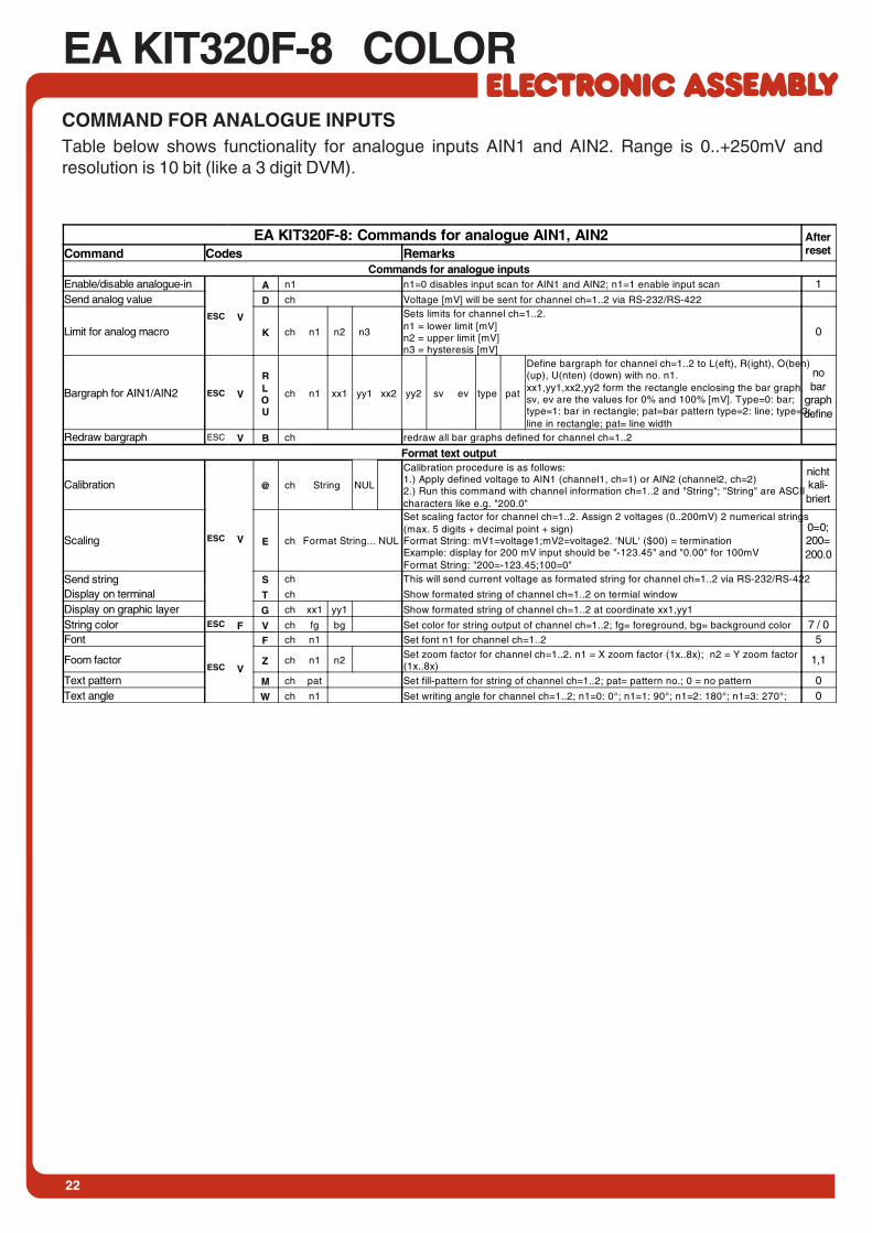
EA KIT320F-8 COLORCOMMAND FOR ANALOGUE INPUTSTable below shows functionality for analogue inputs AIN1 and AIN2. Range is 0..+250mV andresolution is 10 bit (like a 3 digit DVM).
EA KIT320F-8: Commands for analogue AIN1, AIN2 AfterresetCommand Codes Remarks
Commands for analogue inputsEnable/disable analogue-in
ESC V
A n1 n1=0 disables input scan for AIN1 and AIN2; n1=1 enable input scan 1Send analog value D ch Voltage [mV] will be sent for channel ch=1..2 via RS-232/RS-422
Limit for analog macro K ch n1 n2 n3
Sets limits for channel ch=1..2.n1 = lower limit [mV]n2 = upper limit [mV]n3 = hysteresis [mV]
0
Bargraph for AIN1/AIN2 ESC V
RLOU
ch n1 xx1 yy1 xx2 yy2 sv ev type pat
Define bargraph for channel ch=1..2 to L(eft), R(ight), O(ben)(up), U(nten) (down) with no. n1.xx1,yy1,xx2,yy2 form the rectangle enclosing the bar graph.sv, ev are the values for 0% and 100% [mV]. Type=0: bar;type=1: bar in rectangle; pat=bar pattern type=2: line; type=3:line in rectangle; pat= line width
nobar
graphdefine
Redraw bargraph ESC V B ch redraw all bar graphs defined for channel ch=1..2
Format text output
Calibration
ESC V
@ ch String NUL
Calibration procedure is as follows:1.) Apply defined voltage to AIN1 (channel1, ch=1) or AIN2 (channel2, ch=2)2.) Run this command with channel information ch=1..2 and "String"; "String" are ASCIIcharacters like e.g. "200.0"
nichtkali-briert
Scaling E ch Format String... NUL
Set scaling factor for channel ch=1..2. Assign 2 voltages (0..200mV) 2 numerical strings(max. 5 digits + decimal point + sign)Format String: mV1=voltage1;mV2=voltage2. 'NUL' ($00) = terminationExample: display for 200 mV input should be "-123.45" and "0.00" for 100mVFormat String: "200=-123.45;100=0"
0=0;200=200.0
Send string S ch This will send current voltage as formated string for channel ch=1..2 via RS-232/RS-422
Display on terminal T ch Show formated string of channel ch=1..2 on termial window
Display on graphic layer G ch xx1 yy1 Show formated string of channel ch=1..2 at coordinate xx1,yy1
String color ESC F V ch fg bg Set color for string output of channel ch=1..2; fg= foreground, bg= background color 7 / 0Font
ESC V
F ch n1 Set font n1 for channel ch=1..2 5
Foom factor Z ch n1 n2Set zoom factor for channel ch=1..2. n1 = X zoom factor (1x..8x); n2 = Y zoom factor(1x..8x)
1,1
Text pattern M ch pat Set fill-pattern for string of channel ch=1..2; pat= pattern no.; 0 = no pattern 0Text angle W ch n1 Set writing angle for channel ch=1..2; n1=0: 0°; n1=1: 90°; n1=2: 180°; n1=3: 270°; 0
23
COLOR EA KIT320F-8
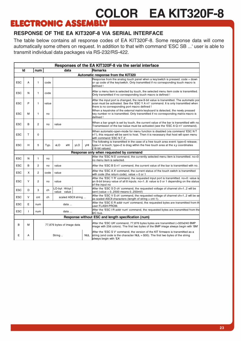
Responses of the EA KIT320F-8 via the serial interfaceId num data Remarks
Automatic response from the KIT320
ESC A 1 codeResponse from the analog touch panel when a key/switch is pressed. code = downor up code of the key/switch. Only transmitted if no corresponding touch macro isdefined !
ESC N 1 codeAfter a menu item is selected by touch, the selected menu item code is transmitted.Only transmitted if no corresponding touch macro is defined !
ESC P 1 valueAfter the input port is changed, the new 8-bit value is transmitted. The automatic porscan must be activated. See the 'ESC Y A n1' command. It is only transmitted whenthere is no corresponding port macro defined !
ESC M 1 noWhen a keystroke of the external matrix keyboard is detected, the newly pressedkey number nr is transmitted. Only transmitted if no corresponding matrix macro isdefined !
ESC B 2 no valueWhen a bar graph is set by touch, the current value of the bar is transmitted with no.Transmission of the bar balue must be activated (see the 'ESC A Q n1' command).
ESC T 0When automatic-open-mode for menu function is disabled (via command 'ESC N Tn1'), this request will be sent to host. Then it is necessary that host will open menuwith command 'ESC N T 2'.
ESC H 5 Typ. xLO xHI yLO yHIThe following is transmitted in the case of a free touch area event: type=0 release;type=1 is touch; type=2 is drag within the free touch area at the x,y coordinates(16-bit values)
Response only when requested by command
ESC N 1 noAfter the 'ESC N S' command, the currently selected menu item is transmitted. no=0:no menu item is selected.
ESC B 2 no value After the 'ESC B S n1' command, the current value of the bar is transmitted with no.
ESC X 2 code valueAfter the 'ESC A X' command, the current status of the touch switch is transmittedwith code (the return code). value = 0 or 1
ESC Y 2 no valueAfter the 'ESC Y R' command, the requested input port is transmitted. no=0: value isan 8-bit binary value of all 8 inputs. no=1..8: value is 0 or 1 depending on the statusof the input no
ESC D 3 chLO-bytvalue
HI-bytvalue
After the 'ESC S D ch' command, the requested voltage of channel ch=1..2 will besent (value = 0..2500 means 0..250mV)
ESC V cnt ch scaled ASCII string ...After the 'ESC V S ch' command, the requested voltage of channel ch=1..2 will be seas scaled ASCII characters (length of string = cnt-1).
ESC E num data ...After the 'ESC E R addr num' command, the requested bytes are transmitted from thuser FLASH-PROM.
ESC I num data ...After the 'ESC I R addr num' command, the requested bytes are transmitted from theI2C bus.
Response without ESC and length specification (num)
B M 77,876 bytes of image dataAfter the 'ESC UH' command, 77,876 bytes bytes are transmitted (=320x240 BMPimage with 256 colors). The first two bytes of the BMP image always begin with 'BM'
E A String .. NULAfter the 'ESC S V' command, the version of the KIT firmware is transmitted as astring (end code is the character NUL = $00). The first two bytes of the stringalways begin with 'EA'
RESPONSE OF THE EA KIT320F-8 VIA SERIAL INTERFACEThe table below contains all response codes of EA KIT320F-8. Some response data will comeautomatically some others on request. In addition to that with command 'ESC SB ...' user is able totransmit individual data packages via RS-232/RS-422.

EA KIT320F-8 COLOR
ZEPPELINSTRASSE 19 · D-82205 GILCHINGPHONE +49-8105-778090 · FAX +49-8105-778099 · http://www.lcd-module.de
DIMENSION
all dimensions are in mm
MOUNTING BEZEL EA 0FP320F-8SW PANEL CUT OUT(also good for blue/white version EA KIT320-8CTP)
all dimensions are in mm
EA 0FP320F-8SW: schwarz eloxiertEA 0FP320F-8SW: schwarz eloxiert
14
5,0
89
,4
10
6,8
81
,0
13
2,0
118,2
185,0
172,0
2,54xM4
148,6
±0
,3
±0,3
12
7,0
165,0
172,0
13
2,0
4x 4,54x Senkung 7mm
4x 4,54x Senkung 7mm

Mouser Electronics
Authorized Distributor
Click to View Pricing, Inventory, Delivery & Lifecycle Information: ELECTRONIC ASSEMBLY:
ea kv24-9b